WO2017090224A1 - 異径筒状体の冷間鍛造による製造方法 - Google Patents
異径筒状体の冷間鍛造による製造方法 Download PDFInfo
- Publication number
- WO2017090224A1 WO2017090224A1 PCT/JP2016/004549 JP2016004549W WO2017090224A1 WO 2017090224 A1 WO2017090224 A1 WO 2017090224A1 JP 2016004549 W JP2016004549 W JP 2016004549W WO 2017090224 A1 WO2017090224 A1 WO 2017090224A1
- Authority
- WO
- WIPO (PCT)
- Prior art keywords
- diameter
- hole
- punching
- punch
- dowel
- Prior art date
- Legal status (The legal status is an assumption and is not a legal conclusion. Google has not performed a legal analysis and makes no representation as to the accuracy of the status listed.)
- Ceased
Links
Images




Classifications
-
- B—PERFORMING OPERATIONS; TRANSPORTING
- B21—MECHANICAL METAL-WORKING WITHOUT ESSENTIALLY REMOVING MATERIAL; PUNCHING METAL
- B21D—WORKING OR PROCESSING OF SHEET METAL OR METAL TUBES, RODS OR PROFILES WITHOUT ESSENTIALLY REMOVING MATERIAL; PUNCHING METAL
- B21D22/00—Shaping without cutting, by stamping, spinning, or deep-drawing
- B21D22/20—Deep-drawing
- B21D22/26—Deep-drawing for making peculiarly, e.g. irregularly, shaped articles
-
- B—PERFORMING OPERATIONS; TRANSPORTING
- B21—MECHANICAL METAL-WORKING WITHOUT ESSENTIALLY REMOVING MATERIAL; PUNCHING METAL
- B21K—MAKING FORGED OR PRESSED METAL PRODUCTS, e.g. HORSE-SHOES, RIVETS, BOLTS OR WHEELS
- B21K21/00—Making hollow articles not covered by a single preceding sub-group
- B21K21/08—Shaping hollow articles with different cross-section in longitudinal direction, e.g. nozzles, spark-plugs
-
- B—PERFORMING OPERATIONS; TRANSPORTING
- B21—MECHANICAL METAL-WORKING WITHOUT ESSENTIALLY REMOVING MATERIAL; PUNCHING METAL
- B21J—FORGING; HAMMERING; PRESSING METAL; RIVETING; FORGE FURNACES
- B21J13/00—Details of machines for forging, pressing, or hammering
- B21J13/02—Dies or mountings therefor
-
- B—PERFORMING OPERATIONS; TRANSPORTING
- B21—MECHANICAL METAL-WORKING WITHOUT ESSENTIALLY REMOVING MATERIAL; PUNCHING METAL
- B21J—FORGING; HAMMERING; PRESSING METAL; RIVETING; FORGE FURNACES
- B21J5/00—Methods for forging, hammering, or pressing; Special equipment or accessories therefor
- B21J5/02—Die forging; Trimming by making use of special dies ; Punching during forging
-
- B—PERFORMING OPERATIONS; TRANSPORTING
- B21—MECHANICAL METAL-WORKING WITHOUT ESSENTIALLY REMOVING MATERIAL; PUNCHING METAL
- B21J—FORGING; HAMMERING; PRESSING METAL; RIVETING; FORGE FURNACES
- B21J5/00—Methods for forging, hammering, or pressing; Special equipment or accessories therefor
- B21J5/06—Methods for forging, hammering, or pressing; Special equipment or accessories therefor for performing particular operations
- B21J5/10—Piercing billets
Definitions
- the present invention is a part having a different diameter cylindrical shape, such as a metal shell which is a main component of a gas sensor for measuring the oxygen concentration of exhaust gas or a metal shell which is a main component of a spark plug.
- the present invention relates to a manufacturing method by cold forging of a different-diameter cylindrical body which is a material before machining of a finished product), that is, a material before being processed into a finished product by cutting or threading as its parts.
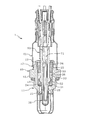
- FIG. 4 is a cross-sectional view (for example, the same structure as the sensor of FIG. 5 of Patent Document 1) 1 of a gas sensor (for example, an oxygen sensor; hereinafter, also simply referred to as a sensor) used in an automobile or the like.
- This sensor 1 includes a metallic shell (metal body) 10 having a different diameter cylindrical shape, a cylindrical detection element (sensor element) 31 having a tip (lower end in the figure) closed inside, and the element 31. It is composed of a protective cylinder 41 and the like which are covered to protect the terminal fittings 71 and 91 in the inside and the sensor.
- the metal shell 10 has a cylindrical structure having a different diameter from the tip toward the rear, which includes a concentric and different diameter cylindrical portion 11, a polygonal portion 15, and a different diameter cylindrical portion 17.
- the inner peripheral surface is formed so as to have a large diameter from the tip toward the rear via a stepped portion, and the inner peripheral surface 22 of the small-diameter hole 21 near the tip and the rear large surface that follows this.
- a rearward-facing annular shelf surface (annular shelf) 24 having a slightly tapered shape is provided at the boundary with the inner peripheral surface 26 of the diameter hole portion 25.
- the element 31 is fixed in the metal shell 10 with an outer flange 33 provided on the outer peripheral surface of the intermediate portion at the front and back thereof being supported by the rearward-facing annular shelf surface 24 via a packing 51 and a holder 52.
- the element 31 is fixed by arranging a sealing material 53, a holder 54, and the like behind the outer flange 33, and a thin-walled cylinder on the rear end side of the cylindrical portion (also referred to as a cylindrical portion) 17 behind the metal shell 10.
- the caulking process is performed by bending the portion 19 to the center line side and compressing and deforming the portion 19 ahead.
- Such a sensor 1 is obtained by turning a polygonal portion 15 to an exhaust pipe of an automobile or the like via a screw 13 provided on an outer peripheral surface of a cylindrical portion (also referred to as a cylindrical portion) 11 on the front end side of the metal shell 10.
- An electromotive force is generated between the inner and outer electrodes based on the difference in oxygen concentration between the inside and outside of the element 31, and a signal based on this is output to the control circuit, and the oxygen concentration in the exhaust gas is detected and empty. Used to control the fuel ratio.
- the front end of the metal shell 10 refers to the lower end in FIG. 4, and the rear end refers to the opposite end.
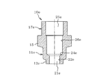
- FIG. 5 shows a tubular body 10e having a different diameter by cold forging, which is a material before machining (a material before cutting or threading), as the metal shell (part finished product) 10 constituting the sensor 1 described above.
- the shape and structure are shown.
- molding mentioned later mentioned later it is a site
- This different-diameter cylindrical body 10e has a polygonal portion (flange) 15 having a relatively large outer diameter and cylindrical portions 11e and 17e sandwiching the polygonal portion (flange) 15 at the front and rear.
- the cylindrical portion 11e on the distal end side has a small diameter cylindrical portion (small diameter portion) 12e whose outer diameter is smaller than the subsequent rearward portion. ing.
- the small-diameter hole portion 21e having a small inner diameter and the large-diameter hole portion 25e having a relatively large inner diameter are coaxial, and the front and rear boundaries of both hole portions are
- a rearward-facing annular shelf surface 24e having a tapered taper is provided.
- the different-diameter cylindrical body 10e in FIG. 5 is a plurality of times obtained by swallowing, drilling, extruding, or a combination of these deformations from a starting material (for example, SUS430) that is usually a cylindrical body obtained by cutting a round bar short. It is manufactured by gradually increasing the deformation through the molding process and finally punching out the portion that should become the small diameter hole 21e (see FIG. 2G of Patent Document 2).
- a spark plug used for ignition of an automobile engine is a cylindrical metal shell of different diameter (metal fitting body) having a screw for mounting (screwing) to the engine on its outer peripheral surface, as is well known.
- a cylindrical insulator that includes a center electrode that is held in the metal shell and protrudes at the tip, and a tip of the metal shell to form a spark gap with the tip of the center electrode. It consists of a welded ground electrode or the like.
- the basic shape and structure of the material before being cut or the like before becoming a metal shell (finished product) for such a spark plug is the same as or similar to that of the sensor, and therefore the material is also described above. It is manufactured by the same process.
- FIG. 6 Such a different diameter cylindrical body 10e is forged also through the following forming processes, for example (refer FIG. 6).
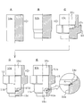
- the first process molded body 10a As shown in FIGS. 6A and 6B, from the starting material, the first process molded body 10a, through two stages of molding processes (first process and second process) such as upsetting by axial compression, extrusion, etc.
- the 2nd process molded object 10b is obtained.
- a hole is formed by punching, and a preliminary hole (concave portion) 25c and a polygonal portion 15 of the large-diameter hole portion 25e are formed on the rear end surface by swaging to obtain a third step molded body 10c (FIG. See 6-C).
- a punch is pushed into the preliminary hole 25c, the tip portion is pushed out, and the large-diameter hole portion 25d is formed at the same time as the deep hole drilling process, and the large-diameter hole portion 25d is formed. 10d is obtained (see FIG. 6-D).
- the bottom surface 27d of the large-diameter hole portion 25d in this molded body is punched out to form the small-diameter hole portion 21e to obtain a different-diameter cylindrical body (fifth-step molded body) 10e (FIG. 6-). E).
- the rear-facing annular shelf surface 24 for supporting the detection element 31 is substantially the third process molded body in the fourth process described above.
- the preliminary hole 25c of 10c is formed by deep drilling (forming the large-diameter hole portion 25d).
- the third step molded body 10c can receive the front part including the polygonal portion 15;
- the deep hole punch 120d is loaded into a die (die) 100d having a cavity formed in the shape part 105d at the front part of the process molded body 10d from the tip side.
- the fourth process molded body 10d which finishes the large-diameter hole portion (bottomed hole) 25d by the pressing.
- the front end surface (the lower end surface in the drawing) of the deep hole punch 120d is formed with a rearward-facing annular shelf surface 24e in the different-diameter cylindrical body 10e at the outer peripheral portion. Is provided with an annular surface (inclined surface) 124d inclined toward the center.
- the subsequent punching process as shown in the left figure (A) of FIG. 8
- the fourth process molded body 10d is loaded into the die 100e for punching, and then the right figure of FIG.
- the first reason for providing the dowel 125d on the tip surface of the deep hole punch 120d in this way is the initial stage of the hole drilling (fourth step), that is, the tip of the punch 120d is pressed against the bottom surface 27c of the preliminary hole 25c.
- the initial stage of the hole drilling fourth step
- the tip of the punch 120d is pressed against the bottom surface 27c of the preliminary hole 25c.
- the dowel 125d in the initial stage of the drilling process of the large-diameter hole portion 25d (until the leading end surface of the dowel 125d is pressed against the bottom surface 27c of the preliminary hole 25c and the pushing is completed) Since the entire surface is not hit by the tip surface of the punch 120d, the load acting on the material can be made relatively small in this initial stage, so that molding without eccentricity can be obtained.
- the tip part is pushed forward in a reduced diameter shape, and deep hole drilling is performed backward.
- a recess 28d corresponding to the dowel 125d (protrusion) is formed at a position near the center of the bottom surface (hole bottom surface) 27d of 25d.
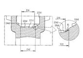
- the outer diameter of the dowel 125d that is, the inner diameter D1 of the recess by the dowel 125d is conventionally the outer diameter of the tip of the punching punch 120e in the fifth step, that is, the rearwardly facing annular shelf in the different diameter cylindrical body 10e.
- the inner diameter of the surface 24 (the inner diameter of the small-diameter hole portion 21) D2 was substantially the same (see paragraph 0057 of Patent Document 2). This is because when the bottom surface 27d of the large-diameter hole portion 25d is punched out, the punching punch 120e can be guided to the inner peripheral surface of the recess 28d by the dowel 125d. In addition, if the tip end surface of the punching punch 120e is set as a taper (tapered) taper earlier than the bottom surface of the recess 28d, the lubricant (oil) remaining in the recess 28d is removed. It can be discharged, and it is possible to prevent deterioration of the finished surface (finished skin) accuracy.
- the large-diameter hole portion 25d is formed with the deep hole punch 120d having the dowel 125d on the tip surface, and then in the fifth step, the recess 28d by the dowel 125d on the bottom surface 27d of the hole is formed.
- the inner peripheral surface of the small-diameter hole 21e is obtained with respect to the different-diameter cylindrical body (finished product) 10e after punching out the above portion and opening the small-diameter hole 21e.
- An internal flaw K such as a crack that extends toward the outside may be generated in a portion close to the rearward annular shelf surface 24e in 22e.
- Such a rear-facing annular shelf surface 24e becomes a metal shell (finished product) through subsequent cutting and screwing of the outer diameter and the like, and supports the detection element and the like as described above when assembled as a sensor. It is a part that forms a support surface and plays a very important role.
- the inventors of the present application conducted various tests and the like on the cause of the internal flaw K, and as a result of repeated investigations and examinations, the cause was known to be as follows.
- the intersection between the outer peripheral surface 127d of the dowel 125d projecting at the tip end surface of the deep hole punch 120d (see FIG. 7) and the tip end surface (annular inclined surface) 124d of the punch 120d outside the dowel 125d used in the fourth step. Is a “corner angle” along the circumferential direction (see an enlarged view in FIG. 7).
- the protruding amount of the dowel 125d is as small as 0.2 to 0.5 mm, but when viewed microscopically, there is a “corner angle” at the intersection.
- the fifth process molded body (different diameter cylindrical body 10e) has a recess 28d due to the dowel 125d on the bottom surface 27d of the large diameter hole 25d of the fourth process molded body 10d.
- a punching punch 120e having an outer diameter D2 substantially coinciding with the inner diameter D1 of the recess 28d, and the small-diameter hole portion 21e is formed. Therefore, the inner circumferential surface 22e of the small-diameter hole portion 21e faces backward.
- An internal flaw K caused by dead metal such as cracks as described above is generated in a portion near the annular shelf surface 24e.
- the different-diameter cylindrical body for the spark plug metal shell also has the same shape and structure having the “rear facing annular shelf surface” as that of the sensor metal shell, and is manufactured in the same manner.
- This shelf surface forms a support surface that supports the insulator surrounding the center electrode, and is an important part.
- the present invention is a part of a gas sensor or a spark plug, and is used for forming a different-diameter cylindrical body for a metal shell having a rear-facing annular shelf surface for supporting an element and an insulator on an inner peripheral surface by cold forging.
- the present invention has been made in view of the above problems, and an object thereof is to prevent the occurrence of internal flaws such as cracks in the annular shelf surface in the subsequent direction in the manufacture of the different-diameter cylindrical body.
- the present invention according to claim 1 has a small-diameter hole portion with a small inner diameter and a large-diameter hole portion with a relatively large inner diameter coaxially from the tip to the rear, It is a manufacturing method by cold forging of a different-diameter cylindrical body having a structure that penetrates in the axial direction with a rearward-facing annular shelf surface that forms a tapered shape at the front and rear boundary, From the columnar starting material, through one or more molding steps, the preliminary hole of the large-diameter hole portion is molded on the rear end surface, After that, to form the large-diameter hole by deep drilling the preliminary hole by pressing a deep hole punch, An annular inclined surface that inclines toward the center so as to form the rearward-facing annular shelf surface of the different-diameter cylindrical body is provided at a portion near the outer periphery of the front end surface of the punch itself, and through the annular inclined surface, By using a deep hole punch that is coaxially provided with
- the present invention described in claim 2 is characterized in that, when the punching punch is driven, the outer peripheral surface of the punching punch is guided by the inner peripheral surface of the large-diameter hole portion deeply drilled by the deep hole punching. It is a manufacturing method by cold forging of the different diameter cylindrical body of Claim 1.
- a communication hole in the punching punch in which the leading end surface of the punching punch communicates with a rear portion thereof so that the leading end surface of the punching punch does not block the recess due to the dowel. It is manufactured, The manufacturing method by cold forging of the different diameter cylindrical body of any one of Claim 1 or 2 characterized by the above-mentioned.
- a deep hole punch in which a dowel protrudes from the tip surface is used for deep hole drilling. Therefore, the intersection between the outer peripheral surface of the dowel and the tip surface of the punch on the outer side is along the circumferential direction. Will become the “edge angle”.
- a dowel-shaped recess is formed at a position near the center of the bottom of the hole. Therefore, the inner peripheral surface of the dent at that stage and the outer side of the dent, and after the punching of the small-diameter hole portion, the intersection with the surface to be the rearward annular shelf surface is convex along the circumferential direction. A corner is formed.
- the outer diameter D1 of the dowel in the deep hole punching is made smaller than the inner diameter D2 of the small diameter hole portion formed by punching (D2> D1). That is, in the present invention, the outer diameter of the dowel (the inner diameter of the dent due to the dowel) D1 is smaller than the punched diameter (the inner diameter D2 of the small diameter hole) of the bottom surface of the large diameter hole. For this reason, after punching, it is a site closer to the inner periphery than the surface to be the rearward circular shelf surface, and is located outside the recess by the dowel, that is, the inner diameter D2 of the small-diameter hole and the outer diameter D1 of the dowel.
- the part between is also punched in this punching.
- the portion (region) between the inner diameter D2 of the small diameter hole and the outer diameter D1 of the dowel is formed. Some are removed as punching waste in the punching.
- the depth of the internal flaw extending radially outward from the inner peripheral surface of the dent due to the dowel is the size of the different-diameter cylindrical body, deep hole drilling It differs depending on the protrusion amount of the dowel in the punch and the fluidity of the metal material to be forged.
- the region where the internal flaw extends radially outward from the inner peripheral surface of the dent by the dowel dowel can be grasped by cutting the test molded product or the like.
- the internal diameter D2 of the said small diameter hole part is set to a predetermined
- the different diameter cylindrical body which is a manufacturing object of the present invention is not limited to the material before machining of the sensor metal shell, and can be applied to the material before machining of the spark plug metal shell.
- the outer peripheral surface of the punch is guided by the inner peripheral surface of the large-diameter hole portion. It is good to leave.
- the outer diameter D2 of the punching punch is larger than the inner diameter D1 of the dent by the dowel.
- the tip surface of the punch closes the dent. Can be prevented.
- the lubricant remaining in the recess can be discharged rearward through the communication hole, so that it is possible to prevent roughening of the molding surface due to the trapping of the lubricant.
- FIG. 5 is a cross-sectional view of a molded body (different diameter cylindrical body) formed by cold forging, which is a material (raw material) before machining of a metal shell (part finished product) used in the gas sensor of FIG. 4.
- FIG. 6 is a half cross-sectional view illustrating an example of a process in which the molded body (different diameter cylindrical body) of FIG. 5 is molded by cold forging and explaining the molded body molded in each step.
- FIG. 6-E the preliminary holes in the third process molded body (FIG. 6-C), which is an intermediate molded body after the preliminary hole formation, are deep drilled.
- the fourth process molded body after deep drilling forming of the large diameter hole
- is punched sectional drawing for process description including the dice
- FIG. 8 is an enlarged view of a P1 portion in FIG. 7 for explaining a scratch generated in the annular shelf surface in the fourth direction after the deep hole drilling (molding of a large diameter hole portion) in FIG. 7 is performed.
- FIGS. 6-E the different-diameter cylindrical body manufactured in this example is the same as that shown in FIG. 5 (FIG. 6-E).
- the manufacturing process is also the same as the process of molding each molded body (A to E) shown in FIG. That is, as shown in FIGS. 6A and 6B, the preliminary hole 25c of the large-diameter hole portion 25d is formed on the rear end surface from the columnar starting material as shown in FIGS. 6A and 6B.
- the third step molded body 10c is molded, and then, in the fourth step, the preliminary hole 25c is deep drilled by pressing a deep hole punch to form a large-diameter hole portion 25d to form a fourth step molded body. Then, the bottom surface 27d of the large-diameter hole portion 25d is punched out by punching in a fifth step to form the small-diameter hole portion 21e to obtain the different-diameter cylindrical body 10e.
- the manufacturing method in the prior art is basically the same, and the difference is substantially the deep punching punch 120d used for deep drilling the preliminary hole 25c in the fourth step (see FIG. 7).
- the outer diameter D1 of the dowel 125d that protrudes forward from the tip surface is only an appropriate amount smaller than the inner diameter D2 of the small-diameter hole portion 21e.
- the third process molded body 10c shown in FIG. The process by which the process molded body (finished product with different diameter cylindrical body) is obtained will be described in more detail, including dies and punches used in the fourth and fifth processes.
- the third process molded body 10c has a cylindrical part on the front end side and a cylindrical part on the rear end side from the second process molded body 10b, and on the outer peripheral surface between the front and rear of both portions, A portion where the polygonal portion 15 is to be formed is formed in an overhanging manner.
- the cylindrical portion on the rear end side is a portion corresponding to the cylindrical portion 17e on the rear end side in the different diameter cylindrical body (see FIG. 5) 10e. As shown in FIG.
- the third process molded body 10c is provided with a recess at the rear end surface (center), and this recess forms a preliminary hole 25c for the large-diameter hole 25.
- the spare hole 25c has a different-diameter hole whose rear end side has a slightly larger diameter with respect to the front end side, and the portion corresponding to the front end side (polygonal portion 15) is then increased by deep drilling.
- the inner diameter of the hole portion is substantially the same as the inner diameter, and the rear inner diameter is slightly larger than the front end side so as to substantially match the inner diameter of the cylindrical portion 17e on the rear end side.
- the bottom surface 27c of the preliminary hole 25c is located in the middle of the front and rear of the polygonal portion 15, and the bottom surface 27c has a small amount and a tapered shape whose center (center) is low. The taper is made.
- the fourth process molded body (FIG. 6-D) 10d that has been deep-drilled in the fourth process from the third process molded body (FIG. 6-C) 10c is a portion ahead of the polygonal portion 15.
- the tip of the (cylindrical part) is reduced in diameter and pushed out, and is also pushed out backward by the deep drilling process to form a large-diameter hole part 25d.
- An intermediate portion (cylinder portion to be threaded) 14d is extended to form a cylindrical portion of a different diameter cylinder having a relatively larger diameter than the small diameter portion 12d.
- the bottom surface 27d of the large-diameter hole portion 25d before being punched and formed as the small-diameter hole portion is set to be located slightly rearward (upward in the drawing) from the tip of the relatively large-diameter portion to be threaded. ing.
- a die 100d used to form a fourth process molded body 10d by deep drilling from a third process molded body 10c having a pre-drilled hole The front part including the polygonal portion 15 is received by a minute gap, and has a cavity formed in the shape 105d of the front part of the fourth process molded body 10d.
- This cavity is capable of molding a cylindrical portion 11e of a different diameter cylinder, a circular hole 106d having a small diameter from the tip side, and an outer peripheral surface of the tip portion of the third process molded body 10c having a larger diameter and a rear side thereof. And is provided with a circular hole 107d for forming a cylindrical portion 11e to be threaded.
- a polygonal hole that can receive the polygonal part 15 in the third process molded body 10c with a minute gap.
- Each hole (cavity) in these dies 100d presents concentric different diameter holes that expand from the front toward the rear.
- the intermediate circular hole 107d is set to be shorter than the front-rear length of the cylindrical portion to be screwed out of the cylindrical portion 11e in view of the backward extrusion (extension) of the material accompanying the deep drilling.
- a knock pin (cylindrical body) 140d is arranged at the lower part of the die 100d for supporting the tip surface of the fourth process molded body 10d and for taking it out after molding.
- the deep hole punch 120d used in the fourth step is capable of forming a large-diameter hole part 25d having a predetermined length and a predetermined diameter by drilling, and a shaft part (cylindrical part) formed so as to be inserted into the preliminary hole 25c. ) 130d.
- the front end surface of the deep hole punch 120d is directed toward the center so as to form a rearward-facing annular shelf surface 24e of the different-diameter cylindrical body (see FIGS. 5 and 6-E) 10e at a portion near the outer periphery.
- An inclined inclined surface 124d is provided.
- a dowel 125d that is circular with a predetermined outer diameter D1 and protrudes a minute amount (0.2 to 0.5 mm) is coaxially provided at the center of the tip surface through the annular inclined surface 124d.
- the outer peripheral edge of the dowel 125d is formed so as to be located on the inner side (center side) from the inner peripheral edge (the inner peripheral surface of the small-diameter hole portion 21e) of the rearward facing annular shelf surface 24e in the different-diameter cylindrical body 10e. Has been.
- the outer diameter D1 of the dowel 125d is generally the same as the inner diameter D2 of the small-diameter hole 21e formed by punching thereafter, but is set to be an appropriate amount smaller than the inner diameter D2 of the small-diameter hole 21e.
- the taper of the annular inclined surface 124d is the same taper as that of the rearwardly facing annular shelf surface 24e of the different-diameter cylindrical body 10e.
- the dowel 125d is also tapered so that the center of the tip surface slightly protrudes. It is tapered.
- the third step molded body 10c is loaded into the die 100d (the left figure (A) in FIG. 1), and as shown in the right figure (B) in FIG.
- the fourth step molded body 10d is obtained by pushing a predetermined amount of the deep hole punch 120d into the (concave portion) 25c.
- the dowel 125d at the front end surface of the deep hole punch 120d is initially pressed against the bottom surface 27c of the preliminary hole 25c, and a recess corresponding to the dowel 125d is formed on the bottom surface 27c.
- the tip portion of the third process molded body 10c is pushed forward in the forward circular hole 106d of the die 100d, and the deep hole drilling advances and the rear portion including the polygonal portion 15 is pushed backward relatively. Then, when the predetermined stroke (predetermined amount) of the deep hole punching punch 120d has been pushed in, the formation of the large diameter hole portion (deep hole drilling) is completed, and the fourth process molded body 10d shown in the right figure (B) of FIG. can get. The tip surface of the deep hole punch 120d is transferred to the bottom surface 27d of the large-diameter hole portion 25d in the fourth process molded body 10d thus obtained.
- a recess 28d is formed by a dowel 125d at the center of the bottom surface 27d, and an annular surface 24d to form the rearward annular shelf surface 24 is formed at an outer portion of the bottom surface 27d, and the inner peripheral surface 29d of the recess 28d is formed.
- the intersection is an angle that is convex along the circumferential direction (see FIG. 2). This is the same as in the conventional process.
- the inner peripheral surface 29d of the recess 28d is outside the bottom surface (or the vicinity thereof) of the recess 28d under the outer annular surface 24d. Internal scratches K due to dead metal such as cracks and wrinkles extending toward the surface may occur. This is also the same as in the conventional process.
- the outer diameter D1 of the dowel 125d in the deep hole punch 120d is made smaller than the inner diameter D2 of the small diameter hole 21e punched and formed by the punch in the next step (fifth step) (FIG. 2). reference).
- the fourth process molded body 10d is then loaded into the die 100e for punching in the fifth process as shown in the left figure (A) of FIG. As shown in FIG.
- an internal flaw K such as a crack existing outside the recess 28 d and inside the diameter D ⁇ b> 2 is formed in the small-diameter hole 21 e ( In the punching), it is removed together with the punching waste U.
- the occurrence of internal flaws in the rear circular ring shelf surface 24e in the different-diameter cylindrical body 10e after the punching is surely reduced as compared with the conventional manufacturing method in which D1 and D2 are substantially the same. it can.
- the die 100e used in the fifth step has substantially the same structure as that in the fourth step, and has a cavity in which the fourth step molded body 10d can be loaded with almost no gap.
- the support (knock pin) 150e at the tip has a pipe structure that does not interfere with the punching punch 120e.
- the punching punch 120e has a shaft portion 125e at the rear portion thereof thicker than a shaft portion (cylindrical portion) of the punching diameter at the tip portion, and is formed on the inner peripheral surface of the large-diameter hole portion 25d in the punching process. It is set to be guided (outer diameter).
- the punch 120e is provided with a hole H for lubricating oil removal having an opening (not shown) and communicating with the front end surface and the rear side surface of the punch.
- how much the outer diameter (dimension) D1 of the dowel 125d in the deep hole punch 120d is determined is the depth of the internal flaw K extending radially outward from the inner peripheral surface of the recess 28d by the dowel 125d, that is, The extent to which internal flaws in the surface that should become the annular shelf surface 24 are determined according to the size, shape, structure, etc. of the different-diameter cylindrical body 10e by cutting the test molded product, etc. As described above, the setting may be made based on the above.
- the outer diameter (dimension) D1 of the dowel 125d may be set so as to include as many internal flaws K as possible in the punching of the small-diameter hole portion 21e and to perform punching removal (simultaneous punching) as punching waste.
- the shaft portion 125e at the rear portion of the punching punch 120e is set to be guided (outer diameter) by the inner peripheral surface of the large-diameter hole portion 25d in the punching process, it is eccentric. There is no need for accurate and stable punching.
- the punching punch 120e is provided with a hole H for lubricating oil communication between the front end surface and the rear side surface of the punch. It can prevent that the front end surface of 120e obstruct
- the different-diameter cylindrical body 10e of this example is provided with a small-diameter cylindrical portion (small-diameter portion) 12e having a relatively small outer diameter at a portion closer to the tip of the cylindrical portion 11e ahead, and a large-diameter hole portion.
- the small-diameter portion to be the small-diameter cylindrical portion (small-diameter portion) 12e is extruded through the small circular hole 106d at the tip of the die 100d.
- the outer diameter D1 of the dowel 125d is set so that the change proceeds as follows in the push process.
- the dowel 125d is pushed so as to dent the bottom surface 27c of the preliminary hole 25c, and the small-diameter portion that should form the small-diameter cylindrical portion (small-diameter portion) 12e is pushed into the circular hole 106d. It is preferable that the large-diameter hole portion 25d obtained by deep hole processing is formed by backward extrusion.
- L1 be a load until the dowel 125d is pushed into the bottom surface 27c of the preliminary hole 25c and the tip surface of the deep hole punch 120d is pressed against the entire bottom surface 27c of the preliminary hole 25c. Thereafter, the load increases as the push-in progresses, and the load until the small-diameter portion that should form the small-diameter cylindrical portion (small-diameter portion) 12e is pushed forward and formed is L2. Next, as the punch 120d is further pushed in and deep hole drilling proceeds, the load until it is pushed backward (elongated) and molding of the large-diameter hole portion 25d (deep hole drilling) is finished is L3.
- the 3rd process molded object 10c which is the case where the different diameter cylindrical body 10e is shape
- the number of steps until the formation of the different-diameter cylindrical body in the present invention is specific to the different-diameter cylindrical body.
- an appropriate number may be set.
- the shape and structure of the different-diameter cylindrical body are not limited to those in the above example, depending on the machining location, machining allowance, etc. What is necessary is just to materialize a different diameter state etc. as a thing of the shape and structure changed suitably.
Landscapes
- Engineering & Computer Science (AREA)
- Mechanical Engineering (AREA)
- Forging (AREA)
Abstract
Description
柱状の出発材料から、1又は複数の成形工程を経て、後端面に前記大径穴部の予備穴を成形し、
その後、該予備穴を深穴あけパンチの押し込みにより深穴あけ加工することで前記大径穴部を成形するのに、
パンチ自身の先端面の外周寄り部位に、前記異径筒状体における前記後方向き環状棚面を成形するように中央に向けて傾斜する環状傾斜面を備えると共に、該環状傾斜面を介し、該先端面の中心には所定の外径で先方に突出するダボを同軸で備えた深穴あけパンチを用いることにより、自身の底面に、前記後方向き環状棚面をなすべき環状面と、該環状面の内側に前記ダボによる凹みとを有する大径穴部を成形し、
その後、打ち抜きパンチの打ち込みにより、該大径穴部の底面を、前記後方向き環状棚面を残存させるように打ち抜くことによって、該後方向き環状棚面と前記小径穴部とを成形する工程を含む、異径筒状体の冷間鍛造による製造方法において、
前記深穴あけパンチにおける前記ダボの外径D1を、前記小径穴部の内径D2より小さくしておくことを特徴とする。
請求項3に記載の本発明は、前記打ち抜きパンチにおける先端面が前記ダボによる凹みを閉塞しないように、該打ち抜きパンチにおける先端面と後方部位とが連通する連通穴が、該打ち抜きパンチ内に設けられていることを特徴とする請求項1又は2のいずれか1項に記載の異径筒状体の冷間鍛造による製造方法である。
21e 小径穴部
24e 後方向き環状棚面
24d 後方向き環状棚面をなすべき環状面
25e 大径穴部
25c 大径穴部の予備穴
25d 大径穴部
27d 大径穴部の底面
28d ダボによる凹み
120d 深穴あけパンチ
124d 深穴あけパンチの先端面の外周寄り部位の環状傾斜面
125d ダボ
120e 打ち抜きパンチ
D1 ダボの外径
D2 小径穴部の内径
Claims (3)
- 先端から後方に、内径が小径の小径穴部と、内径が相対的に大径の大径穴部とを同軸で有し、しかも、その両穴部の先後の境界に、先すぼまり状をなす後方向き環状棚面を有して軸線方向に貫通する構造を有する異径筒状体の冷間鍛造による製造方法であって、
柱状の出発材料から、1又は複数の成形工程を経て、後端面に前記大径穴部の予備穴を成形し、
その後、該予備穴を深穴あけパンチの押し込みにより深穴あけ加工することで前記大径穴部を成形するのに、
パンチ自身の先端面の外周寄り部位に、前記異径筒状体における前記後方向き環状棚面を成形するように中央に向けて傾斜する環状傾斜面を備えると共に、該環状傾斜面を介し、該先端面の中心には所定の外径で先方に突出するダボを同軸で備えた深穴あけパンチを用いることにより、自身の底面に、前記後方向き環状棚面をなすべき環状面と、該環状面の内側に前記ダボによる凹みとを有する大径穴部を成形し、
その後、打ち抜きパンチの打ち込みにより、該大径穴部の底面を、前記後方向き環状棚面を残存させるように打ち抜くことによって、該後方向き環状棚面と前記小径穴部とを成形する工程を含む、異径筒状体の冷間鍛造による製造方法において、
前記深穴あけパンチにおける前記ダボの外径D1を、前記小径穴部の内径D2より小さくしておくことを特徴とする、異径筒状体の冷間鍛造による製造方法。 - 前記打ち抜きパンチの打ち込みにおいて、該打ち抜きパンチの外周面を、前記深穴あけパンチによって深穴あけされた前記大径穴部の内周面にてガイドさせることを特徴とする請求項1に記載の異径筒状体の冷間鍛造による製造方法。
- 前記打ち抜きパンチにおける先端面が前記ダボによる凹みを閉塞しないように、該打ち抜きパンチにおける先端面と後方部位とが連通する連通穴が、該打ち抜きパンチ内に設けられていることを特徴とする請求項1又は2のいずれか1項に記載の異径筒状体の冷間鍛造による製造方法。
Priority Applications (4)
| Application Number | Priority Date | Filing Date | Title |
|---|---|---|---|
| CN201680067789.XA CN108290205B (zh) | 2015-11-24 | 2016-10-12 | 异径筒状体的利用冷锻制造的制造方法 |
| US15/778,329 US10828686B2 (en) | 2015-11-24 | 2016-10-12 | Method for manufacturing cylindrical body having different diameters by cold forging |
| KR1020187014330A KR102283076B1 (ko) | 2015-11-24 | 2016-10-12 | 이경 통상체의 냉간 단조에 의한 제조 방법 |
| DE112016005366.5T DE112016005366B4 (de) | 2015-11-24 | 2016-10-12 | Verfahren zur Herstellung eines Zylinderkörpers mit unterschiedlichen Durchmessern durch Kaltschmieden |
Applications Claiming Priority (2)
| Application Number | Priority Date | Filing Date | Title |
|---|---|---|---|
| JP2015228934A JP6532813B2 (ja) | 2015-11-24 | 2015-11-24 | 異径筒状体の冷間鍛造による製造方法 |
| JP2015-228934 | 2015-11-24 |
Publications (1)
| Publication Number | Publication Date |
|---|---|
| WO2017090224A1 true WO2017090224A1 (ja) | 2017-06-01 |
Family
ID=58764130
Family Applications (1)
| Application Number | Title | Priority Date | Filing Date |
|---|---|---|---|
| PCT/JP2016/004549 Ceased WO2017090224A1 (ja) | 2015-11-24 | 2016-10-12 | 異径筒状体の冷間鍛造による製造方法 |
Country Status (6)
| Country | Link |
|---|---|
| US (1) | US10828686B2 (ja) |
| JP (1) | JP6532813B2 (ja) |
| KR (1) | KR102283076B1 (ja) |
| CN (1) | CN108290205B (ja) |
| DE (1) | DE112016005366B4 (ja) |
| WO (1) | WO2017090224A1 (ja) |
Families Citing this family (6)
| Publication number | Priority date | Publication date | Assignee | Title |
|---|---|---|---|---|
| CN110899605B (zh) * | 2019-10-12 | 2021-08-31 | 江苏力野精工科技有限公司 | 一种汽车底盘避震器壳体整体式冷锻拉伸方法 |
| CN112001049B (zh) * | 2020-08-24 | 2024-04-30 | 苏州萨伯工业设计有限公司 | 内六面体冲削制造方法 |
| CN112517817A (zh) * | 2020-10-30 | 2021-03-19 | 攀钢集团江油长城特殊钢有限公司 | 一种薄壁异形台阶筒件的自由锻造工艺 |
| CN112570611B (zh) * | 2020-11-25 | 2022-11-08 | 湖北三环锻造有限公司 | 一种差速器壳挤压冲孔工艺 |
| CN115889658A (zh) * | 2022-11-18 | 2023-04-04 | 烯晶碳能电子科技无锡有限公司 | 电极套管的冷镦加工工艺 |
| WO2025254984A1 (en) * | 2024-06-03 | 2025-12-11 | Metal Forming & Coining, Llc | Polygonal rotor shaft with formed end cap |
Citations (5)
| Publication number | Priority date | Publication date | Assignee | Title |
|---|---|---|---|---|
| JP2000094080A (ja) * | 1998-09-17 | 2000-04-04 | Nippon Koshuha Steel Co Ltd | リング状部品の製造方法 |
| JP2002011543A (ja) * | 2000-06-30 | 2002-01-15 | Ngk Spark Plug Co Ltd | 筒状金具の製造方法 |
| JP2007278806A (ja) * | 2006-04-05 | 2007-10-25 | Ngk Spark Plug Co Ltd | ガスセンサの製造方法 |
| JP2007307601A (ja) * | 2006-05-22 | 2007-11-29 | Sanyo Special Steel Co Ltd | 熱間または温間鍛造用の金型 |
| WO2015056373A1 (ja) * | 2013-10-14 | 2015-04-23 | 日本特殊陶業株式会社 | スパークプラグの主体金具成形品の製造方法、スパークプラグの主体金具の製造方法、及びスパークプラグの製造方法 |
Family Cites Families (11)
| Publication number | Priority date | Publication date | Assignee | Title |
|---|---|---|---|---|
| US3186209A (en) * | 1960-04-14 | 1965-06-01 | Nat Machinery Co | Method of cold forming an elongated hollow article |
| KR890002206B1 (ko) | 1986-04-25 | 1989-06-23 | 주식회사 금성사 | 피어싱 금형의 스크랩부착 방지장치 |
| KR890004134B1 (ko) * | 1987-07-20 | 1989-10-21 | 한국과학 기술원 | 페닐디클로로포스핀의 제조방법 |
| JPH0620577B2 (ja) * | 1988-04-14 | 1994-03-23 | 日本特殊陶業株式会社 | 塑性加工による点火栓用端子ナットの製造方法 |
| JP2729852B2 (ja) * | 1990-08-07 | 1998-03-18 | 本田技研工業株式会社 | ボール継手用外輪の成形に用いられるしごき加工用ポンチの製造方法 |
| JP4147704B2 (ja) | 1999-10-21 | 2008-09-10 | 株式会社デンソー | スパークプラグ用主体金具の製造方法 |
| JP3936230B2 (ja) * | 2002-04-19 | 2007-06-27 | 日本特殊陶業株式会社 | フランジ付き筒状金具の製造方法 |
| CN100416265C (zh) * | 2003-06-27 | 2008-09-03 | 日本特殊陶业株式会社 | 传感器的制造方法和传感器 |
| JP4741687B2 (ja) * | 2009-03-03 | 2011-08-03 | 日本特殊陶業株式会社 | スパークプラグ用主体金具の製造方法 |
| JP5535097B2 (ja) | 2011-01-14 | 2014-07-02 | 日本特殊陶業株式会社 | スパークプラグ用主体金具の製造方法およびスパークプラグの製造方法 |
| KR20190028158A (ko) * | 2017-09-08 | 2019-03-18 | 백승민 | 교체형 피어싱 펀치 |
-
2015
- 2015-11-24 JP JP2015228934A patent/JP6532813B2/ja active Active
-
2016
- 2016-10-12 KR KR1020187014330A patent/KR102283076B1/ko active Active
- 2016-10-12 US US15/778,329 patent/US10828686B2/en active Active
- 2016-10-12 CN CN201680067789.XA patent/CN108290205B/zh active Active
- 2016-10-12 DE DE112016005366.5T patent/DE112016005366B4/de active Active
- 2016-10-12 WO PCT/JP2016/004549 patent/WO2017090224A1/ja not_active Ceased
Patent Citations (5)
| Publication number | Priority date | Publication date | Assignee | Title |
|---|---|---|---|---|
| JP2000094080A (ja) * | 1998-09-17 | 2000-04-04 | Nippon Koshuha Steel Co Ltd | リング状部品の製造方法 |
| JP2002011543A (ja) * | 2000-06-30 | 2002-01-15 | Ngk Spark Plug Co Ltd | 筒状金具の製造方法 |
| JP2007278806A (ja) * | 2006-04-05 | 2007-10-25 | Ngk Spark Plug Co Ltd | ガスセンサの製造方法 |
| JP2007307601A (ja) * | 2006-05-22 | 2007-11-29 | Sanyo Special Steel Co Ltd | 熱間または温間鍛造用の金型 |
| WO2015056373A1 (ja) * | 2013-10-14 | 2015-04-23 | 日本特殊陶業株式会社 | スパークプラグの主体金具成形品の製造方法、スパークプラグの主体金具の製造方法、及びスパークプラグの製造方法 |
Also Published As
| Publication number | Publication date |
|---|---|
| US10828686B2 (en) | 2020-11-10 |
| DE112016005366B4 (de) | 2022-10-13 |
| JP6532813B2 (ja) | 2019-06-19 |
| CN108290205A (zh) | 2018-07-17 |
| KR102283076B1 (ko) | 2021-07-28 |
| US20180345347A1 (en) | 2018-12-06 |
| DE112016005366T5 (de) | 2018-08-02 |
| CN108290205B (zh) | 2019-07-16 |
| JP2017094356A (ja) | 2017-06-01 |
| KR20180073632A (ko) | 2018-07-02 |
Similar Documents
| Publication | Publication Date | Title |
|---|---|---|
| KR102283076B1 (ko) | 이경 통상체의 냉간 단조에 의한 제조 방법 | |
| US9643238B2 (en) | Manufacturing method of metal shell formed body for spark plug, manufacturing method of metal shell for spark plug, and spark plug manufacturing method | |
| US4352283A (en) | Method of forming spark plug bodies | |
| JP4147704B2 (ja) | スパークプラグ用主体金具の製造方法 | |
| US8322184B2 (en) | Method of producing metallic shell for spark plug | |
| US8042270B2 (en) | Method of manufacturing hose coupling fitting | |
| JP6612600B2 (ja) | 多角形フランジ付き筒状金具の冷間鍛造による製造方法 | |
| JP6109709B2 (ja) | 異径筒状成形体の冷間鍛造による製造方法、及びガスセンサ用主体金具の製造方法 | |
| JP3431950B2 (ja) | スパークプラグ用主体金具の製造方法 | |
| US7073256B2 (en) | Method of manufacturing center electrode for spark plug | |
| JPH01262032A (ja) | 塑性加工による点火栓用端子ナットの製造方法 | |
| JP4880563B2 (ja) | スパークプラグ用の主体金具の製造方法 | |
| JP5335489B2 (ja) | グロープラグ用の主体金具の製造方法 | |
| RU2254199C1 (ru) | Способ изготовления заготовок самоконтрящихся гаек с нейлоновым кольцом и фланцем | |
| JP3471410B2 (ja) | スパークプラグ用主体金具の製造方法 | |
| JPH0446652A (ja) | 主体金具の製造方法 | |
| JP2013202690A (ja) | 管状部品の塑性加工方法 | |
| JP2006136909A (ja) | 棒状部材の製造方法 | |
| RU2097158C1 (ru) | Способ прессования труб | |
| SU1074634A1 (ru) | Способ изготовлени тонкостенных осесимметричных деталей из трубчатых заготовок | |
| JP2561516B2 (ja) | フューエルインジェクタコアの製造方法 | |
| JPH0420714A (ja) | グロープラグ用主体金具の製造方法 | |
| JP2000161326A (ja) | ネジ部材、雌ネジ部材の製造方法および金属材の加工方法 | |
| TH1801002990A (th) | วิธีการสำหรับการผลิตส่วนลำตัวรูปทรงกระบอกซึ่งมีขนาดเส้นผ่านศูนย์กลางต่างกันด้วยการตีขึ้นรูปเย็น |
Legal Events
| Date | Code | Title | Description |
|---|---|---|---|
| 121 | Ep: the epo has been informed by wipo that ep was designated in this application |
Ref document number: 16868175 Country of ref document: EP Kind code of ref document: A1 |
|
| ENP | Entry into the national phase |
Ref document number: 20187014330 Country of ref document: KR Kind code of ref document: A |
|
| WWE | Wipo information: entry into national phase |
Ref document number: 112016005366 Country of ref document: DE |
|
| 122 | Ep: pct application non-entry in european phase |
Ref document number: 16868175 Country of ref document: EP Kind code of ref document: A1 |