WO2017082045A1 - 電動圧縮機 - Google Patents
電動圧縮機 Download PDFInfo
- Publication number
- WO2017082045A1 WO2017082045A1 PCT/JP2016/081606 JP2016081606W WO2017082045A1 WO 2017082045 A1 WO2017082045 A1 WO 2017082045A1 JP 2016081606 W JP2016081606 W JP 2016081606W WO 2017082045 A1 WO2017082045 A1 WO 2017082045A1
- Authority
- WO
- WIPO (PCT)
- Prior art keywords
- motor
- temperature
- inverter
- electric compressor
- upper limit
- Prior art date
- Legal status (The legal status is an assumption and is not a legal conclusion. Google has not performed a legal analysis and makes no representation as to the accuracy of the status listed.)
- Ceased
Links
Images






Classifications
-
- F—MECHANICAL ENGINEERING; LIGHTING; HEATING; WEAPONS; BLASTING
- F25—REFRIGERATION OR COOLING; COMBINED HEATING AND REFRIGERATION SYSTEMS; HEAT PUMP SYSTEMS; MANUFACTURE OR STORAGE OF ICE; LIQUEFACTION SOLIDIFICATION OF GASES
- F25B—REFRIGERATION MACHINES, PLANTS OR SYSTEMS; COMBINED HEATING AND REFRIGERATION SYSTEMS; HEAT PUMP SYSTEMS
- F25B49/00—Arrangement or mounting of control or safety devices
- F25B49/02—Arrangement or mounting of control or safety devices for compression type machines, plants or systems
- F25B49/025—Motor control arrangements
-
- F—MECHANICAL ENGINEERING; LIGHTING; HEATING; WEAPONS; BLASTING
- F04—POSITIVE - DISPLACEMENT MACHINES FOR LIQUIDS; PUMPS FOR LIQUIDS OR ELASTIC FLUIDS
- F04B—POSITIVE-DISPLACEMENT MACHINES FOR LIQUIDS; PUMPS
- F04B35/00—Piston pumps specially adapted for elastic fluids and characterised by the driving means to their working members, or by combination with, or adaptation to, specific driving engines or motors, not otherwise provided for
- F04B35/04—Piston pumps specially adapted for elastic fluids and characterised by the driving means to their working members, or by combination with, or adaptation to, specific driving engines or motors, not otherwise provided for the means being electric
-
- F—MECHANICAL ENGINEERING; LIGHTING; HEATING; WEAPONS; BLASTING
- F04—POSITIVE - DISPLACEMENT MACHINES FOR LIQUIDS; PUMPS FOR LIQUIDS OR ELASTIC FLUIDS
- F04B—POSITIVE-DISPLACEMENT MACHINES FOR LIQUIDS; PUMPS
- F04B49/00—Control, e.g. of pump delivery, or pump pressure of, or safety measures for, machines, pumps, or pumping installations, not otherwise provided for, or of interest apart from, groups F04B1/00 - F04B47/00
- F04B49/06—Control using electricity
-
- F—MECHANICAL ENGINEERING; LIGHTING; HEATING; WEAPONS; BLASTING
- F04—POSITIVE - DISPLACEMENT MACHINES FOR LIQUIDS; PUMPS FOR LIQUIDS OR ELASTIC FLUIDS
- F04C—ROTARY-PISTON, OR OSCILLATING-PISTON, POSITIVE-DISPLACEMENT MACHINES FOR LIQUIDS; ROTARY-PISTON, OR OSCILLATING-PISTON, POSITIVE-DISPLACEMENT PUMPS
- F04C18/00—Rotary-piston pumps specially adapted for elastic fluids
- F04C18/02—Rotary-piston pumps specially adapted for elastic fluids of arcuate-engagement type, i.e. with circular translatory movement of co-operating members, each member having the same number of teeth or tooth-equivalents
- F04C18/0207—Rotary-piston pumps specially adapted for elastic fluids of arcuate-engagement type, i.e. with circular translatory movement of co-operating members, each member having the same number of teeth or tooth-equivalents both members having co-operating elements in spiral form
- F04C18/0215—Rotary-piston pumps specially adapted for elastic fluids of arcuate-engagement type, i.e. with circular translatory movement of co-operating members, each member having the same number of teeth or tooth-equivalents both members having co-operating elements in spiral form where only one member is moving
-
- F—MECHANICAL ENGINEERING; LIGHTING; HEATING; WEAPONS; BLASTING
- F04—POSITIVE - DISPLACEMENT MACHINES FOR LIQUIDS; PUMPS FOR LIQUIDS OR ELASTIC FLUIDS
- F04C—ROTARY-PISTON, OR OSCILLATING-PISTON, POSITIVE-DISPLACEMENT MACHINES FOR LIQUIDS; ROTARY-PISTON, OR OSCILLATING-PISTON, POSITIVE-DISPLACEMENT PUMPS
- F04C23/00—Combinations of two or more pumps, each being of rotary-piston or oscillating-piston type, specially adapted for elastic fluids; Pumping installations specially adapted for elastic fluids; Multi-stage pumps specially adapted for elastic fluids
- F04C23/008—Hermetic pumps
-
- F—MECHANICAL ENGINEERING; LIGHTING; HEATING; WEAPONS; BLASTING
- F04—POSITIVE - DISPLACEMENT MACHINES FOR LIQUIDS; PUMPS FOR LIQUIDS OR ELASTIC FLUIDS
- F04C—ROTARY-PISTON, OR OSCILLATING-PISTON, POSITIVE-DISPLACEMENT MACHINES FOR LIQUIDS; ROTARY-PISTON, OR OSCILLATING-PISTON, POSITIVE-DISPLACEMENT PUMPS
- F04C28/00—Control of, monitoring of, or safety arrangements for, pumps or pumping installations specially adapted for elastic fluids
- F04C28/08—Control of, monitoring of, or safety arrangements for, pumps or pumping installations specially adapted for elastic fluids characterised by varying the rotational speed
-
- F—MECHANICAL ENGINEERING; LIGHTING; HEATING; WEAPONS; BLASTING
- F04—POSITIVE - DISPLACEMENT MACHINES FOR LIQUIDS; PUMPS FOR LIQUIDS OR ELASTIC FLUIDS
- F04B—POSITIVE-DISPLACEMENT MACHINES FOR LIQUIDS; PUMPS
- F04B2203/00—Motor parameters
- F04B2203/02—Motor parameters of rotating electric motors
- F04B2203/0201—Current
-
- F—MECHANICAL ENGINEERING; LIGHTING; HEATING; WEAPONS; BLASTING
- F04—POSITIVE - DISPLACEMENT MACHINES FOR LIQUIDS; PUMPS FOR LIQUIDS OR ELASTIC FLUIDS
- F04B—POSITIVE-DISPLACEMENT MACHINES FOR LIQUIDS; PUMPS
- F04B2203/00—Motor parameters
- F04B2203/02—Motor parameters of rotating electric motors
- F04B2203/0209—Rotational speed
-
- F—MECHANICAL ENGINEERING; LIGHTING; HEATING; WEAPONS; BLASTING
- F04—POSITIVE - DISPLACEMENT MACHINES FOR LIQUIDS; PUMPS FOR LIQUIDS OR ELASTIC FLUIDS
- F04B—POSITIVE-DISPLACEMENT MACHINES FOR LIQUIDS; PUMPS
- F04B49/00—Control, e.g. of pump delivery, or pump pressure of, or safety measures for, machines, pumps, or pumping installations, not otherwise provided for, or of interest apart from, groups F04B1/00 - F04B47/00
- F04B49/10—Other safety measures
-
- F—MECHANICAL ENGINEERING; LIGHTING; HEATING; WEAPONS; BLASTING
- F04—POSITIVE - DISPLACEMENT MACHINES FOR LIQUIDS; PUMPS FOR LIQUIDS OR ELASTIC FLUIDS
- F04C—ROTARY-PISTON, OR OSCILLATING-PISTON, POSITIVE-DISPLACEMENT MACHINES FOR LIQUIDS; ROTARY-PISTON, OR OSCILLATING-PISTON, POSITIVE-DISPLACEMENT PUMPS
- F04C2240/00—Components
- F04C2240/40—Electric motor
- F04C2240/403—Electric motor with inverter for speed control
-
- F—MECHANICAL ENGINEERING; LIGHTING; HEATING; WEAPONS; BLASTING
- F04—POSITIVE - DISPLACEMENT MACHINES FOR LIQUIDS; PUMPS FOR LIQUIDS OR ELASTIC FLUIDS
- F04C—ROTARY-PISTON, OR OSCILLATING-PISTON, POSITIVE-DISPLACEMENT MACHINES FOR LIQUIDS; ROTARY-PISTON, OR OSCILLATING-PISTON, POSITIVE-DISPLACEMENT PUMPS
- F04C2240/00—Components
- F04C2240/80—Other components
- F04C2240/808—Electronic circuits (e.g. inverters) installed inside the machine
-
- F—MECHANICAL ENGINEERING; LIGHTING; HEATING; WEAPONS; BLASTING
- F04—POSITIVE - DISPLACEMENT MACHINES FOR LIQUIDS; PUMPS FOR LIQUIDS OR ELASTIC FLUIDS
- F04C—ROTARY-PISTON, OR OSCILLATING-PISTON, POSITIVE-DISPLACEMENT MACHINES FOR LIQUIDS; ROTARY-PISTON, OR OSCILLATING-PISTON, POSITIVE-DISPLACEMENT PUMPS
- F04C2270/00—Control; Monitoring or safety arrangements
- F04C2270/19—Temperature
-
- F—MECHANICAL ENGINEERING; LIGHTING; HEATING; WEAPONS; BLASTING
- F25—REFRIGERATION OR COOLING; COMBINED HEATING AND REFRIGERATION SYSTEMS; HEAT PUMP SYSTEMS; MANUFACTURE OR STORAGE OF ICE; LIQUEFACTION SOLIDIFICATION OF GASES
- F25B—REFRIGERATION MACHINES, PLANTS OR SYSTEMS; COMBINED HEATING AND REFRIGERATION SYSTEMS; HEAT PUMP SYSTEMS
- F25B2600/00—Control issues
- F25B2600/02—Compressor control
- F25B2600/021—Inverters therefor
Definitions
- This disclosure relates to an electric compressor that compresses and feeds a supplied refrigerant.
- the electric compressor operates the compression mechanism by the driving force of the motor, compresses the supplied refrigerant, and sends it out.
- Such an electric compressor is used as an apparatus for circulating a refrigerant in a refrigeration cycle.
- the electric compressor described in the following Patent Document 1 has a configuration in which a motor, an inverter for supplying a driving current to the motor, and a compression mechanism for compressing a refrigerant are housed in a casing. .
- the compression mechanism is disposed at a position that is on the most downstream side along the flow of the refrigerant.
- the motor and the inverter are arranged at positions upstream of the compression mechanism along the refrigerant flow.
- the overall size of the electric compressor is relatively large.
- the electric compressor described in the following Patent Document 2 is arranged at a position where substantially the entire compression mechanism is inside the motor, specifically, inside the stator and rotor of the motor. That is, the compression mechanism and the motor are arranged at substantially the same position. For this reason, it has a more compact configuration than the electric compressor described in Patent Document 1 below.
- the refrigerant which has evaporated in the evaporator and has become low temperature and low pressure is supplied to the electric compressor. Inside the electric compressor, the refrigerant becomes high temperature and high pressure by being compressed by the compression mechanism.
- the present disclosure has been made in view of such a problem, and an object of the present disclosure is to prevent a decrease in torque even when the temperature of a motor is increased by being heated by a compressed high-temperature refrigerant. It is in providing the electric compressor which can be performed.
- an electric compressor is an electric compressor (10) that compresses and feeds a supplied refrigerant, and is driven by the motor (140) and compresses the refrigerant.
- a compression mechanism 150
- an inverter 130
- a control device 180
- the inverter is disposed at a position upstream of the compression mechanism along the refrigerant flow and is cooled by the refrigerant, and the motor is heated by the refrigerant compressed by the compression mechanism.
- the control device changes the upper limit value for the drive current supplied to the motor based on at least one of the first information that is information related to the temperature of the motor and the second information that is information related to the temperature of the inverter. .
- the upper limit value for the drive current is changed based on at least one of the first information and the second information. For example, if the upper limit value is changed to be larger than the normal value when the motor is at a high temperature, the torque necessary for operating the compression mechanism can be ensured.
- the inverter heat generation increases, so that the inverter may become hot and the operation may become unstable.
- the inverter of the electric compressor having the above-described configuration is disposed at a position upstream of the compression mechanism and cooled by the refrigerant. For this reason, even if the heat generation amount of the inverter increases due to the change of the upper limit value, it is possible to prevent the inverter temperature from excessively rising.
- an electric compressor capable of preventing a decrease in torque even when heated by a compressed high-temperature refrigerant and the temperature of the motor is increased.
- FIG. 1 is a diagram schematically illustrating the overall configuration of the electric compressor according to the first embodiment.
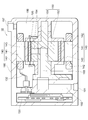
- FIG. 2 is a cross-sectional view showing the internal configuration of the electric compressor.
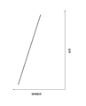
- FIG. 3 is a graph showing the relationship between the motor temperature and the magnetic flux density.
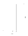
- FIG. 4 is a graph showing changes in torque when the motor is at a high temperature.
- FIG. 5 is a flowchart showing a flow of processing executed by the control device for the electric compressor.
- FIG. 6 is a flowchart showing a flow of processing executed by the control device for the electric compressor.
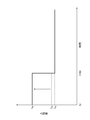
- FIG. 7 is a graph showing changes in the upper limit value set for the drive current.
- FIG. 8 is a graph showing changes in torque when the motor is at a high temperature.
- FIG. 1 is a diagram schematically illustrating the overall configuration of the electric compressor according to the first embodiment.
- FIG. 2 is a cross-sectional view showing the internal configuration of the electric compressor.
- FIG. 3 is a graph showing the relationship between the motor temperature
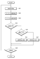
- FIG. 9 is a flowchart showing a flow of processing executed by the control device for the electric compressor according to the second embodiment.
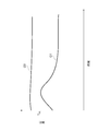
- FIG. 10 is a graph showing changes in the temperature of the inverter and changes in the temperature of the motor.
- FIG. 11 is a flowchart showing a flow of processing executed by the control device for the electric compressor according to the third embodiment.
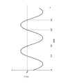
- FIG. 12 is a graph showing changes in torque of the compression mechanism.
- FIG. 13 is a graph showing changes in torque of the compression mechanism.
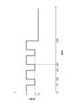
- FIG. 14 is a graph showing changes in the upper limit value set for the drive current.
- the configuration of the electric compressor 10 according to the first embodiment will be described with reference to FIG.
- the electric compressor 10 is configured as a device for circulating a refrigerant in a refrigeration cycle (not shown).
- the electric compressor 10 compresses the low-temperature and low-pressure refrigerant supplied from the evaporator disposed on the upstream side into a high-temperature and high-temperature state by compressing the refrigerant inside, and then to the condenser disposed on the downstream side. It will be sent out.
- the electric compressor 10 includes a high voltage battery 110, a relay system 120, an inverter 130, a motor 140, a compression mechanism 150, and a control device 180.
- a drive circuit 160 and a detection circuit 170 are provided between the inverter 130 and the control device 180.
- the high voltage battery 110 is a power storage device that outputs a direct current.
- the direct current output from the high voltage battery 110 is converted into an alternating current by an inverter 130 described later, and supplied to the motor 140 as a drive current.
- the high voltage battery 110 may be provided as a dedicated power storage device for supplying current to the electric compressor 10, but supplies direct current to not only the electric compressor 10 but also other power consuming devices. It may be provided as something to do.
- the relay system 120 is provided at a position between the high voltage battery 110 and the inverter 130.
- the relay system 120 includes three relays 121, 122, and 123 and a protective resistor 124. By the opening / closing operation of the relays 121, 122, and 123, supply and interruption of current between the high voltage battery 110 and the inverter 130 are switched.
- the relay 121 and the relay 123 are first closed while the relay 121 remains open. At this time, since the current from the high voltage battery 110 passes through the protective resistor 124, the occurrence of an excessive inrush current due to the application of the high voltage is suppressed. Thereafter, the relay 121 is closed and the relay 122 is opened. The opening / closing operation of the relays 121, 122, 123 is controlled by the control device 180. When any abnormality occurs in the electric compressor 10, the relays 121, 122, and 123 are opened, and the current supply from the high voltage battery 110 is cut off.
- the inverter 130 is a circuit for converting a direct current supplied from the high voltage battery 110 into a three-phase alternating current and supplying this to the motor 140 as a drive current. As shown in FIG. 1, the inverter 130 is configured as a three-phase full-bridge inverter circuit.
- the inverter 130 is equipped with six switching elements 131 each composed of an IGBT and a reflux diode, and these constitute three upper arms and three lower arms.
- the magnitude of the drive current supplied to the motor 140 is adjusted by the duty of the switching operation performed by these.
- a smoothing circuit including capacitors 101 and 103 and a coil 102 is provided.
- the smoothing circuit smoothes the direct current input to the inverter 130.
- a voltmeter 104 is provided in the vicinity of the capacitor 103.
- the voltmeter 104 is for measuring the voltage applied to both ends of the capacitor 103, that is, the voltage of the DC power input to the inverter 130.
- the voltage value measured by the voltmeter 104 is input to the detection circuit 170.
- An ammeter 105 is provided between the output portion of the inverter 130, that is, between the inverter 130 and the motor 140.
- the ammeter 105 is for measuring the magnitude of the driving current supplied from the inverter 130 to the motor 140.
- the current value measured by the ammeter 105 is input to the detection circuit 170.
- the motor 140 is a rotating electric machine that operates by receiving an alternating current consisting of three phases of U phase, V phase, and W phase. When a driving current is supplied to the motor 140, the driving force of the motor 140 is transmitted to the compression mechanism 150, and the compression of the refrigerant by the compression mechanism 150 is performed.
- the motor 140 and the compression mechanism 150 are schematically illustrated so as to be separated from each other in FIG. 1, the motor 140 and the compression mechanism 150 are actually provided at substantially the same position. These specific arrangements will be described later with reference to FIG.
- the drive circuit 160 is a circuit for generating a drive signal for causing the inverter 130 to perform a switching operation and transmitting the drive signal to the inverter 130.
- the drive signal is generated based on a modulation signal transmitted from the control device 180 to the drive circuit 160. That is, it can be said that the control device 180 transmits a drive signal to the inverter 130 via the drive circuit 160 and thereby controls the switching operation of the inverter 130.
- the drive circuit 160 may be provided as a separate device from the control device 180, but may be provided inside the control device 180.
- the detection circuit 170 is a circuit for receiving signals from sensors arranged in each part of the electric compressor 10, appropriately converting each signal and transmitting the signals to the control device 180.
- the control device 180 can grasp the state quantity detected by each sensor based on the signal transmitted from the detection circuit 170.
- the detection circuit 170 may be provided as a separate device from the control device 180, but may be provided inside the control device 180. In FIG. 1, only the voltmeter 104 and the ammeter 105 that have already been described among the sensors arranged in each part of the electric compressor 10 are illustrated.
- the inverter 130 is provided with a temperature sensor (not shown) for measuring the temperature of the inverter 130.
- the temperature of the inverter 130 measured by the temperature sensor is transmitted to the control device 180 via the detection circuit 170.
- the “temperature of the inverter 130” is, for example, the temperature in the vicinity of the switching element 131 in the circuit board constituting the inverter 130.
- the motor 140 is provided with a temperature sensor (not shown) for measuring the temperature of the motor 140.
- the temperature of the motor 140 measured by the temperature sensor is transmitted to the control device 180 via the detection circuit 170.
- the “temperature of the motor 140” is, for example, the temperature in the stator of the motor 140 or in the vicinity thereof.
- the control device 180 is a device that controls the overall operation of the electric compressor 10.
- the control device 180 is configured as a computer system including a CPU, a ROM, a RAM, a communication interface, and the like.
- the control device 180 controls the switching operation of the inverter 130 by transmitting a modulation signal to the drive circuit 160 so that an appropriate drive current is supplied to the motor 140.
- the control device 180 controls the opening / closing operation of the relay system 120 to switch between supply and interruption of current between the high voltage battery 110 and the inverter 130.
- the control device 180 has an upper limit calculator 181 and a current controller 182 as functional control blocks.
- the upper limit calculator 181 is a part that calculates and sets an upper limit for the driving current supplied from the inverter 130 to the motor 140.
- the current control unit 182 is a part that transmits a modulation signal to the drive circuit 160 and controls the drive current output from the inverter 130. The current control unit 182 adjusts the modulation signal transmitted to the drive circuit 160 so that the drive current falls below the upper limit value.
- the control device 180 controls the inverter 130 and the like while communicating with the host control device 20.
- the ECU for vehicle control or the ECU for air conditioning control corresponds to the host controller 20.
- the control device 180 controls the overall operation of the electric compressor 10 according to the operation request transmitted from the host control device 20.
- FIG. 2 shows an internal configuration of the casing 190 in the electric compressor 10. 1, the high voltage battery 110, the relay system 120, the drive circuit 160, the detection circuit 170, and the control device 180 are all arranged outside the casing 190. Therefore, these illustrations are omitted in FIG.
- the casing 190 is a container formed entirely in a substantially cylindrical shape. Inside the casing 190, flow paths (192, 193, 194, 195, 196) through which the refrigerant passes are formed. The most upstream end of the channel is open on the side surface of the casing 190. The opening is a refrigerant inlet 191. Further, the most downstream end of the flow path is also open on the side surface of the casing 190. The opening is a refrigerant outlet 197.
- a shaft 151 that is a part of the compression mechanism 150 is fixed inside the casing 190.
- the shaft 151 is an elongated cylindrical shaft.
- the central axis of the shaft 151 is parallel to the central axis of the casing 190.
- a flow path 193 is formed inside the shaft 151 along the central axis.
- a rotor 152 that is a part of the compression mechanism 150 is disposed outside the shaft 151.
- the rotor 152 is composed of two cylindrical bodies. These cylindrical bodies are eccentric from each other, and all of them are provided around the shaft 151 in a rotatable state.
- the rotor 152 rotates accordingly.
- the shape of the gap in the rotor 152 changes. Thereby, the refrigerant is compressed in the gap.
- the compressed refrigerant passes through the flow path 195 and the flow path 196 in order, and then is sent out from the outlet 197 to the outside.
- a flow path 194 is formed in the cylindrical body disposed on the inner side.
- the flow path 194 is a flow path that connects a flow path 193 formed inside the shaft 151 and a gap inside the rotor 152.
- the refrigerant passes through the flow path 193 and the flow path 194 in order, reaches the gap of the rotor 152, and is compressed in the gap as described above.
- a motor 140 is disposed outside the rotor 152.
- the motor 140 has a stator 141 and a rotor 143.
- the rotor 143 is formed in a cylindrical shape, and the rotor 152 is accommodated therein. Further, the inner peripheral surface of the rotor 143 is fixed to the rotor 152. For this reason, when the rotor 143 rotates, the rotor 152 rotates with it.
- the rotor 143 is provided with a plurality of permanent magnets.
- the stator 141 is formed in a cylindrical shape, and the rotor 143 is accommodated therein.
- the stator 141 is fixed to the inner peripheral surface of the casing 190.
- the stator 141 holds a coil 142.
- the coil 142 is a portion through which a driving current supplied from the inverter 130 flows. The driving current is supplied from the inverter 130 to the coil 142 via the conductive wire 132.
- the flow path 192 is a flow path that connects the flow path 193 formed in the shaft 151 and the inlet 191. Since the refrigerant passing through the flow path 192 is the refrigerant before being compressed by the compression mechanism 150, it has a low temperature and a low pressure.
- the inverter 130 is disposed inside the casing 190 at a position opposite to the motor 140 across the flow path 192. That is, it is disposed at a position upstream of the compression mechanism 150 along the refrigerant flow.
- the flow path 192 is a flow path formed along the inverter 130 in the vicinity of the inverter 130. For this reason, when a low-temperature refrigerant flows through the flow path 192, the inverter 130 is cooled by the refrigerant.
- the motor 140 is disposed so as to surround the periphery of the compression mechanism 150. Further, the distance between the motor 140 and the compression mechanism 150 is relatively small. For this reason, when the electric compressor 10 is operated and the refrigerant is compressed by the compression mechanism 150, the motor 140 is heated by the refrigerant that has been compressed and has reached a high temperature.
- the torque N 10 of the compression mechanism 150 may fall below the required torque N R required for the electric compressor 10 to exhibit its performance.
- the rotational angle of the rotor 143 in the motor 140 that is, the phase is indefinite, so that the necessary torque N R is larger than that in the steady operation.
- the electric compressor 10 is temporarily stopped and then restarted within a relatively short time, since the temperature of the motor 140 is high, a torque higher than the necessary torque N R is applied. There is a possibility that it cannot be output and it cannot be restarted.
- the upper limit value calculated by the upper limit value calculation unit 181 is normally set. It is configured to be larger than the time. Thereby, the drive current supplied to the motor 140 can be temporarily increased, and the torque of the compression mechanism 150 can be made equal to or higher than the required torque N R.
- an operation flag is acquired.
- the operation flag is a signal periodically transmitted from the host control device 20 to the control device 180. Whether the electric compressor 10 is operated (turned on) or stopped (turned off). ).
- the operation flag may be a signal indicating a specific physical quantity, such as a rotation speed instruction, instead of a signal indicating ON or OFF as described above.
- step S02 it is determined whether or not the acquired operation flag is ON, that is, whether or not the host controller 20 has instructed to operate the electric compressor 10. If the operation flag is OFF, the processes after step S01 are repeatedly executed. If the operation flag is ON, the process proceeds to step S03.
- step S03 activation control is performed.
- the start-up control the drive current from the inverter 130 is supplied to the motor 140, and thereby the rotor 152 of the compression mechanism 150 starts to rotate.
- step S03 After the start control in step S03 is performed, when the rotational speed of the rotor 152 is increased and becomes stable, the process proceeds to step S04 and a steady operation is performed.
- step S05 following step S04 the operation flag is acquired again. At this time, the steady operation of the electric compressor 10 is continuously performed.
- step S06 following step S05, as in step S02, it is determined whether or not the acquired operation flag is ON. If the operation flag is ON, the processes after step S04 are repeatedly executed, and the steady operation of the electric compressor 10 is continued. If the operation flag is OFF, the process proceeds to step S07.
- step S07 stop control is performed.
- the stop control is control performed to stop the operation of the electric compressor 10.
- the process proceeds to step S08.
- step S08 an elapsed time from when the stop control is completed is measured.
- step S09 it is determined whether or not the measured elapsed time exceeds a predetermined time.
- This predetermined time is set in advance as the time required for the temperature of the motor 140 to drop to near room temperature after the electric compressor 10 is stopped. In other words, it is set in advance as the time required for the temperature of the motor 140 to fall to such an extent that the reduction of the magnetic flux density in the motor 140 does not become a problem.
- step S03 the processing after step S03 is executed again.
- step S09 if the elapsed time does not exceed the predetermined time, the process proceeds to step S10. In step S10, the operation flag is acquired again.
- step S11 it is determined whether or not the acquired operation flag is ON, as in steps S02 and S06. If the operation flag is OFF, the processing after step S08 is repeatedly executed. If the operation flag is ON, the process proceeds to step S12. In step S12, a process for restarting the stopped electric compressor 10 is performed. When the restart is completed, the processes after step S04 are executed again.
- the process performed in step S12 is a process for restarting the electric compressor 10 within a relatively short time after the electric compressor 10 is stopped (that is, before the predetermined time has elapsed). is there.
- this process is also referred to as “high temperature restart process”.
- the aspect of the restart process at high temperature is different from the conventional one.
- step S12 the specific contents of the restart process (ie, the high temperature restart process) performed in step S12 will be described.
- the temperature of the motor 140 is acquired via the detection circuit 170.
- step S122 following step S121 the temperature of the inverter 130 is acquired via the detection circuit 170.
- step S123 the upper limit value for the driving current is calculated and set by the upper limit calculation unit 181 based on the temperature of the motor 140 and the temperature of the inverter 130.
- step S124 activation control similar to step S03 in FIG. 5 is performed. However, during the start-up control, the drive current is adjusted within a range that is equal to or less than the set upper limit value.
- FIG. 7 shows an example of a change in the upper limit value.
- the restart of the electric compressor 10 is completed at time t ⁇ b> 100 and a steady operation is performed thereafter.
- the upper limit value for the drive current is a value I that is larger than the upper limit value (value I 10 ) in the period in which the steady operation is performed. It is set to 30 .
- reference numeral “I 15 ” in FIG. 7 indicates that the start-up control in step S03 in FIG. 5 is performed when the electric compressor 10 is started with the motor 140 at room temperature. This is the upper limit value set when The time when the normal start-up as described above is performed is also referred to as “normal start-up” below.
- the pressure of the refrigerant in the casing 190 is equal on the upstream side and the downstream side of the compression mechanism 150, and the temperature of the motor 140 and the temperature of the inverter 130 are equal. Thus, it can also be defined when the operation of the motor 140 is started.
- the value I 15, which is the upper limit value set during normal startup, is set as a value slightly larger than the upper limit value (value I 10 ) in the period during which steady operation is performed.
- the upper limit value (value I 30 ) set in step S123 is larger than the upper limit value (value I 15 ) set at the time of normal activation.
- the upper limit value for the drive current supplied to the motor 140 is changed from the value I 15 to the value I 30 based on the temperature of the motor 140 and the temperature of the inverter 130. Yes. Thereby, the value of the drive current at the time of restart increases.
- the torque N 20 of the compression mechanism 150 is larger than the torque N 10 shown in FIG. 4 and larger than the required torque N R. For this reason, in the motor 140, the magnetic flux density is reduced due to the temperature rise, but the compression and delivery of the refrigerant by the electric compressor 10 is performed stably.
- the inverter 130 When the upper limit value of the drive current increases as described above, the amount of heat generated by the inverter 130 increases accordingly. For this reason, it seems that the inverter 130 becomes high temperature and the operation becomes unstable. However, in the electric compressor 10 having the configuration shown in FIG. 2, the inverter 130 is arranged at a position upstream of the compression mechanism 150 and cooled by the refrigerant. For this reason, even if the heat generation amount of the inverter 130 increases due to the change of the upper limit value, the temperature of the inverter 130 is prevented from excessively rising.
- the upper limit value that is set may be increased as the temperature of the motor 140 increases. Further, the upper limit value that is set may be increased as the temperature of the inverter 130 decreases.
- the relationship between the temperature of the motor 140 and the temperature of the inverter 130 and the upper limit value set based on the temperature is created in advance as a map based on experiments and the like, and is stored in the ROM of the control device 180. Is desirable.
- the upper limit value of the drive current is set based on both the temperature of the motor 140 and the temperature of the inverter 130.
- the upper limit value may be set based on only one of the temperature of the motor 140 and the temperature of the inverter 130.
- the setting of the upper limit value is not performed based on the measured value of the temperature of the motor 140, but may be performed based on information indirectly indicating the temperature of the motor 140.
- the “information that indirectly indicates the temperature of the motor 140” include an elapsed time after the motor 140 stops.
- the upper limit value may be set based on the temperature of the motor 140 or information indirectly indicating the temperature (these correspond to “information on temperature” of the motor 140).
- the setting of the upper limit value may not be performed based on the measured value of the temperature of the inverter 130 but may be performed based on information that indirectly indicates the temperature of the inverter 130.
- the “information that indirectly indicates the temperature of the inverter 130” include a switching cycle of the switching element 131 and the like.
- the upper limit value may be set based on the temperature of the inverter 130 or information indirectly indicating the temperature (these correspond to “information about temperature” of the inverter 130).
- the second embodiment will be described.
- the second embodiment is different from the first embodiment in the contents of the high temperature restart process, and the other is the same as in the first embodiment.
- the high temperature restart process in the second embodiment will be described with reference to FIG.
- the series of processes shown in FIG. 9 is executed in place of the series of processes shown in FIG.
- the processing performed in the first step S121 and the subsequent step S122 is the same as the processing performed in step S121 and step S122 shown in FIG.
- step S1220 it is determined whether or not the temperature of the inverter 130 is equal to or lower than a predetermined threshold temperature.
- the temperature of the inverter 130 is acquired through the detection circuit 170.
- the threshold temperature is set in advance as a value within a temperature range in which the switching operation in the inverter 130 is appropriately performed.
- step S123 When the temperature of the inverter 130 is equal to or lower than the threshold temperature, the process proceeds to step S123.
- the processing performed in step S123 and the subsequent step S124 is the same as the processing performed in step S123 and step S124 shown in FIG.
- the upper limit value is changed to a value larger than the upper limit value (value I 15 ) at the time of normal startup, so that the torque of the compression mechanism 150 is increased to be equal to or higher than the required torque N R.
- step S1220 If the temperature of the inverter 130 exceeds the threshold temperature in step S1220, the process proceeds to step S124 without passing through step S123. That is, the upper limit value is not changed, and the activation control in step S124 is performed with the upper limit value (value I 15 ) at the normal activation being maintained.
- the control device 180 is configured to change the upper limit value only when the temperature of the inverter 130 is equal to or lower than the predetermined threshold temperature. Therefore, as shown in FIG. 10, even when the temperature (G2) of the motor 140 is high, the temperature (line G1) of the inverter 130 does not exceed the temperature upper limit TUL . For this reason, it is reliably prevented that the temperature of the inverter 130 rises too much and the operation becomes unstable.
- the temperature upper limit T UL is a temperature corresponding to the upper limit of the temperature range in which the switching operation in the inverter 130 is appropriately performed. It said threshold temperature is set as a temperature lower than the temperature limit T UL.
- the third embodiment will be described.
- the third embodiment is different from the first embodiment in terms of the contents of the high temperature restart process, and is otherwise the same as in the first embodiment.
- the high temperature restart process in the third embodiment will be described with reference to FIG.
- the series of processing shown in FIG. 11 is executed in place of the processing in step S124 shown in FIG.
- step S21 activation control similar to that in step S03 in FIG. 3 is started.
- the drive current from the inverter 130 is supplied to the motor 140, whereby the rotor 152 of the compression mechanism 150 starts to rotate.
- step S22 the process immediately proceeds to step S22 without waiting for the start control to end.
- step S22 the temperature of the motor 140 is acquired again via the detection circuit 170.
- step S23 following step S22 the temperature of the inverter 130 is acquired again via the detection circuit 170.
- step S24 whether the temperature of the motor 140 is less than a predetermined set temperature T A is determined.
- the set temperature T A is set in advance as a temperature that is low enough that the magnetic flux density in the motor 140 hardly causes a problem.
- the upper limit value for the drive current is the value I 15 (that is, the upper limit value set during normal startup).
- step S24 When the temperature of the motor 140 exceeds the set temperature T A in step S24, the process proceeds to step S25. At step S25, whether the temperature of the motor 140 is below a predetermined set temperature T B is determined. Setting the temperature T B is one that is set in advance as a temperature higher than the set temperature T A.
- step S26 the upper limit value of the driving current is set to a value I 20.
- the value I 20 is preset as a value smaller than the value I 30 shown in FIG. 7 and larger than the value I 15 .
- the driving current supplied from the inverter 130 to the motor 140 is adjusted within a range of the value I 20 or less.
- step S25 when the temperature of the motor 140 exceeds the set temperature T B, the process proceeds to step S27.
- step S27 the upper limit value of the driving current is set to a value I 30.
- the value I 30 is set in advance as a value larger than any of the values I 10 , I 15 , and I 20 . Thereafter, the driving current supplied from the inverter 130 to the motor 140 is adjusted within a range of the value I 30 or less.
- step S28 it is determined whether or not the start control has been completed and the operation has shifted to a steady operation. If the process has not yet shifted to the steady operation, the processes after step S21 are executed again. If it has shifted to the steady operation, the series of processing shown in FIG. 11 is terminated. Thereafter, the processing after step S05 shown in FIG. 5 is executed.
- the upper limit value for the drive current is changed stepwise based on the information related to the temperature of the motor 140. For example, if the temperature of the motor 140 gradually decreases during the high temperature restart process, the upper limit value is changed step by step in the order of the value I 30 , the value I 20 , and the value I 15. Will go. By changing the upper limit value step by step, an appropriate upper limit value is set according to the situation at each time point.
- the upper limit value is changed in three steps, but the number of steps may be four or more, or two or less.
- the upper limit value is changed stepwise based on the temperature of the motor 140, but the upper limit value may be changed stepwise based on information about the temperature of the inverter 130.
- the upper limit value may be changed stepwise based on both information related to the temperature of motor 140 and information related to the temperature of inverter 130.
- the compression mechanism 150 is configured to repeat the compression and delivery of the refrigerant by rotating the rotor 152. For this reason, the torque of the compression mechanism 150 is not always constant, but periodically fluctuates in synchronization with the change in the rotation angle of the rotor 152.
- FIG. 12 shows an example of a change in torque that varies as described above.
- FIG. 12 shows a change in torque of the compression mechanism 150 when the upper limit value is set as described above.
- the torque of the compression mechanism 150 is less than the required torque N R during the period from time t0 to time t10, the period from time t20 to time t30, and the period after time t40. It has become.
- the upper limit of the driving current only in a period as described above, may be modified to be a value larger than the upper limit value in a normal start (the value I 15).
- FIG. 14 shows an example of the change in the upper limit value changed in this way. Until the time t100 when the restart is completed, the torque of the compression mechanism 150 can always be equal to or higher than the necessary torque N R by repeatedly changing the upper limit value between the value I 15 and the value I 30 .
- the control device 180 in the example of FIG. 14 changes the upper limit value in synchronization with torque fluctuation so that the torque of the compression mechanism 150 is always equal to or greater than the required torque N R.
- the upper limit value is changed from the value I15 only when the electric compressor 10 is restarted.
- the upper limit value may be changed according to the temperature of the motor 140 or the like.
Landscapes
- Engineering & Computer Science (AREA)
- Mechanical Engineering (AREA)
- General Engineering & Computer Science (AREA)
- Physics & Mathematics (AREA)
- Thermal Sciences (AREA)
- Control Of Positive-Displacement Pumps (AREA)
- Control Of Ac Motors In General (AREA)
- Control Of Motors That Do Not Use Commutators (AREA)
Abstract
インバータ(130)は、冷媒の流れに沿って圧縮機構(150)よりも上流側となる位置であって、且つ冷媒により冷却される位置に配置されている。モーター(140)は、圧縮機構(150)で圧縮された冷媒により加熱される位置に配置されている。制御装置(180)は、モーター(140)の温度に関する情報である第1情報と、インバータ(130)の温度に関する情報である第2情報と、の少なくとも一方に基づいて、モーター(140)に供給される駆動用電流についての上限値を変更する。
Description
本出願は、2015年11月12日に出願された日本国特許出願2015-221763号に基づくものであって、その優先権の利益を主張するものであり、その特許出願の全ての内容が、参照により本明細書に組み込まれる。
本開示は、供給された冷媒を圧縮して送り出す電動圧縮機に関する。
電動圧縮機は、モーターの駆動力によって圧縮機構を動作させ、供給された冷媒を圧縮して外部に送り出すものである。このような電動圧縮機は、冷凍サイクルにおいて冷媒を循環させるための装置として用いられる。
下記特許文献1に記載された電動圧縮機は、モーターと、モーターに駆動用電流を供給するためのインバータと、冷媒を圧縮する圧縮機構とが、ケーシングの内部に収納された構成となっている。これらのうち圧縮機構は、冷媒の流れに沿って最も下流側となる位置に配置されている。モーター及びインバータは、冷媒の流れに沿って圧縮機構よりも上流側となる位置に配置されている。このように、モーターと圧縮機構とが冷媒の流れ方向に沿って並ぶように配置されているので、電動圧縮機の全体のサイズは比較的大きくなっている。
下記特許文献2に記載された電動圧縮機は、圧縮機構の略全体がモーターの内部、具体的には、モーターの固定子及び回転子の内側となる位置に配置されている。つまり、圧縮機構とモーターとがほぼ同じ位置に配置されている。このため、下記特許文献1に記載された電動圧縮機に比べてコンパクトな構成となっている。
冷凍サイクルにおいては、蒸発器において蒸発し低温且つ低圧となった冷媒が電動圧縮機に供給される。電動圧縮機の内部では、冷媒は圧縮機構において圧縮されることにより高温且つ高圧となる。
従って、上記特許文献2に記載された電動圧縮機のように、モーターの近くに圧縮機構が配置されている場合には、モーターは高温の冷媒によって加熱され、その温度を上昇させることとなる。その結果、モーターの磁束密度が低下してしまい、圧縮機構を動作させるために必要なトルクを出力することができなくなってしまう可能性がある。
特に、電動圧縮機の起動時においては、圧縮機構に求められるトルクが大きくなる。従って、電動圧縮機が停止した後、比較的短時間のうちに再起動する場合には、モーターの温度が高い状態となっているために必要なトルクを出力することができず、再起動ができなくなってしまう可能性がある。
本開示はこのような課題に鑑みてなされたものであり、その目的は、圧縮された高温の冷媒により加熱され、モーターの温度が上昇した場合であっても、トルクの低下を防止することのできる電動圧縮機を提供することにある。
上記課題を解決するために、本開示に係る電動圧縮機は、供給された冷媒を圧縮して送り出す電動圧縮機(10)であって、モーター(140)と、モーターによって駆動され、冷媒を圧縮する圧縮機構(150)と、モーターに駆動用電流を供給するインバータ(130)と、インバータの動作を制御する制御装置(180)と、を備える。インバータは、冷媒の流れに沿って圧縮機構よりも上流側となる位置であって、且つ冷媒により冷却される位置に配置されており、モーターは、圧縮機構で圧縮された冷媒により加熱される位置に配置されている。制御装置は、モーターの温度に関する情報である第1情報と、インバータの温度に関する情報である第2情報と、の少なくとも一方に基づいて、モーターに供給される駆動用電流についての上限値を変更する。
このような電動圧縮機では、第1情報及び第2情報の少なくとも一方に基づいて、駆動用電流についての上限値が変更される。例えば、モーターが高温となっているときには上限値を通常時よりも大きくなるように変更すれば、圧縮機構を動作させるために必要なトルクを確保することができる。
尚、駆動用電流の上限値を通常よりも大きくした場合には、インバータの発熱が大きくなるので、インバータが高温となり動作が不安定となってしまうようにも思われる。しかしながら、上記のような構成における電動圧縮機のインバータは、圧縮機構よりも上流側となる位置であって、且つ冷媒により冷却される位置に配置されている。このため、上限値の変更によってインバータの発熱量が増加しても、インバータの温度が上昇し過ぎてしまうことは防止される。
本開示によれば、圧縮された高温の冷媒により加熱され、モーターの温度が上昇した場合であっても、トルクの低下を防止することのできる電動圧縮機が提供される。
以下、添付図面を参照しながら本実施形態について説明する。説明の理解を容易にするため、各図面において同一の構成要素に対しては可能な限り同一の符号を付して、重複する説明は省略する。
図1を参照しながら、第1実施形態に係る電動圧縮機10の構成について説明する。電動圧縮機10は、冷凍サイクル(不図示)において冷媒を循環させるための装置として構成されている。電動圧縮機10は、上流側に配置された蒸発器から供給される低温且つ低圧の冷媒を、内部で圧縮することにより高温且つ高温の状態とした上で、下流側に配置された凝縮器へと送り出すものである。
図1に模式的に示されるように、電動圧縮機10は、高電圧バッテリー110と、リレーシステム120と、インバータ130と、モーター140と、圧縮機構150と、制御装置180とを備えている。また、インバータ130と制御装置180との間には、駆動回路160と検出回路170とが設けられている。
高電圧バッテリー110は、直流の電流を出力する蓄電装置である。高電圧バッテリー110から出力された直流電流は、後述のインバータ130によって交流電流に変換され、駆動用電流としてモーター140に供給される。尚、高電圧バッテリー110は、電動圧縮機10に電流を供給するための専用の蓄電装置として設けられてもよいのであるが、電動圧縮機10のみならず他の電力消費機器に直流電流を供給するものとして設けられていてもよい。
リレーシステム120は、高電圧バッテリー110とインバータ130との間となる位置に設けられている。リレーシステム120は、3つのリレー121、122、123と、保護抵抗124とを有している。リレー121、122、123の開閉動作により、高電圧バッテリー110とインバータ130との間における電流の供給及び遮断が切り換えられる。
高電圧バッテリー110からの電流の供給が開始される際には、先ず、リレー121は開状態のままで、リレー122とリレー123とが閉状態とされる。このとき、高電圧バッテリー110からの電流は保護抵抗124を通ることになるので、高電圧の印加に伴う過剰な突入電流の発生が抑制される。その後、リレー121が閉状態とされ、リレー122が開状態とされる。リレー121、122、123の開閉動作は、制御装置180により制御される。電動圧縮機10で何らかの異常が生じた際には、リレー121、122、123が開状態とされ、高電圧バッテリー110からの電流の供給が遮断される。
インバータ130は、高電圧バッテリー110から供給される直流電流を三相交流電流に変換し、これを駆動用電流としてモーター140に供給するための回路である。図1に示されるように、インバータ130は3相フルブリッジインバータ回路として構成されている。
インバータ130には、IGBTと還流ダイオードとから構成されたスイッチング素子131が6つ搭載されており、これらによって3つの上アームと3つの下アームとが構成されている。これらが行うスイッチング動作のデューティにより、モーター140に供給される駆動用電流の大きさが調整される。
リレーシステム120とインバータ130との間には、コンデンサ101、103、及びコイル102からなる平滑回路が設けられている。当該平滑回路により、インバータ130に入力される直流電流が平滑化される。
コンデンサ103の近傍には電圧計104が設けられている。電圧計104は、コンデンサ103の両端に印加されている電圧、すなわち、インバータ130に入力されている直流電力の電圧を測定するためのものである。電圧計104により計測された電圧値は検出回路170に入力される。
インバータ130の出力部、すなわち、インバータ130とモーター140との間には、電流計105が設けられている。電流計105は、インバータ130からモーター140に供給される駆動用電流の大きさを測定するためのものである。電流計105により計測された電流値は検出回路170に入力される。
モーター140は、U相、V相、W相の3相からなる交流電流の供給を受けて動作する回転電機である。モーター140に駆動用電流が供給されると、モーター140の駆動力が圧縮機構150に伝達され、圧縮機構150による冷媒の圧縮が行われる。尚、モーター140と圧縮機構150とは、図1においては互いに離間するように模式的に描かれているのであるが、実際には両者はほぼ同じ位置に設けられている。これらの具体的な配置については、後に図2を参照しながら説明する。
駆動回路160は、インバータ130にスイッチング動作を行わせるための駆動信号を生成し、当該駆動信号をインバータ130に送信するための回路である。駆動信号は、制御装置180から駆動回路160に送信される変調信号に基づいて生成されるものである。つまり、制御装置180は、駆動回路160を介して駆動信号をインバータ130に送信し、これによりインバータ130のスイッチング動作を制御するもの、ということができる。駆動回路160は、制御装置180とは別体の装置として設けられてもよいが、制御装置180の内部に設けられていてもよい。
検出回路170は、電動圧縮機10の各部に配置されたセンサからの信号を受信し、それぞれの信号を適宜変換して制御装置180に伝達するための回路である。制御装置180は、検出回路170から伝達される信号に基づいて、各センサによって検知された状態量を把握することができる。検出回路170は、制御装置180とは別体の装置として設けられてもよいが、制御装置180の内部に設けられていてもよい。図1においては、電動圧縮機10の各部に配置されたセンサのうち、既に説明した電圧計104及び電流計105のみが図示されている。
インバータ130には、インバータ130の温度を測定するための不図示の温度センサが設けられている。当該温度センサで測定されたインバータ130の温度は、検出回路170を介して制御装置180へと伝達される。尚、「インバータ130の温度」とは、例えば、インバータ130を構成する回路基板のうち、スイッチング素子131の近傍部分における温度のことである。
モーター140には、モーター140の温度を測定するための不図示の温度センサが設けられている。当該温度センサで測定されたモーター140の温度は、検出回路170を介して制御装置180へと伝達される。尚、「モーター140の温度」とは、例えば、モーター140のうち固定子又はその近傍部分における温度のことである。
制御装置180は、電動圧縮機10の全体の動作を制御する装置である。制御装置180は、CPU、ROM、RAM、通信インターフェイス等を備えたコンピュータシステムとして構成されている。制御装置180は、モーター140に適切な駆動用電流が供給されるように、駆動回路160に変調信号を送信することによってインバータ130のスイッチング動作を制御する。また、制御装置180は、リレーシステム120の開閉動作を制御することにより、高電圧バッテリー110とインバータ130との間における電流の供給及び遮断の切り換えを行う。
制御装置180は、機能的な制御ブロックとして、上限値演算部181と、電流制御部182とを有している。上限値演算部181は、インバータ130からモーター140に供給される駆動用電流についての上限値を算出し設定する部分である。電流制御部182は、駆動回路160に変調信号を送信し、インバータ130から出力される駆動用電流の制御を行う部分である。電流制御部182は、駆動用電流が上限値以下に収まるように、駆動回路160に送信される変調信号を調整する。
制御装置180は、上位制御装置20と通信を行いながらインバータ130等の制御を行う。車両に搭載される冷凍システムの一部として電動圧縮機10が用いられる場合には、車両制御用のECU又は空調制御用のECUが上位制御装置20に該当する。制御装置180は、上位制御装置20から送信される動作要求に従って、電動圧縮機10の全体の動作を制御する。
図2を参照しながら、電動圧縮機10の具体的な構成について説明する。図2には、電動圧縮機10のうち、ケーシング190の内部の構成が示されている。尚、図1に示されている構成のうち、高電圧バッテリー110、リレーシステム120、駆動回路160、検出回路170、及び制御装置180は、いずれもケーシング190の外部に配置されている。従って、図2においてはこれらの図示が省略されている。
ケーシング190は、その全体が略円柱形状に形成された容器である。ケーシング190の内部には、冷媒が通る流路(192、193、194、195、196)が形成されている。当該流路のうち最も上流側の端部はケーシング190の側面において開口している。当該開口は冷媒の入口191となっている。また、上記流路のうち最も下流側の端部もケーシング190の側面において開口している。当該開口は冷媒の出口197となっている。
ケーシング190の内部には、圧縮機構150の一部であるシャフト151が固定されている。シャフト151は、細長い円柱形状のシャフトである。シャフト151の中心軸は、ケーシング190の中心軸に対して平行となっている。シャフト151の内部には、中心軸に沿って流路193が形成されている。
シャフト151の外側には、圧縮機構150の一部であるローター152が配置されている。ローター152は、二つの筒状体によって構成されている。これら筒状体は互いに偏心しており、いずれもシャフト151の周りに回転可能な状態で設けられている。モーター140に駆動用電流が供給され、モーター140の回転子143が回転すると、それに伴ってローター152も回転する。その際、ローター152内における隙間(二つの筒状体の間に形成された隙間)の形状が変化する。これにより、当該隙間において冷媒が圧縮される。圧縮された冷媒は、流路195、流路196を順に通った後、出口197から外部へと送り出される。
ローター152を構成する二つの筒状体のうち、内側に配置された方の筒状体には、流路194が形成されている。流路194は、シャフト151の内部に形成された流路193と、ローター152の内部の隙間とを連通させる流路となっている。ローター152が回転すると、冷媒は流路193、流路194を順に通ってローター152の隙間に到達し、上記のように当該隙間において圧縮される。
ローター152の外側には、モーター140が配置されている。モーター140は、固定子141と回転子143とを有している。
回転子143は円筒状に形成されており、その内部にローター152を収納している。また、回転子143は、その内周面がローター152に対して固定されている。このため、回転子143が回転すると、それに伴ってローター152も共に回転する。回転子143には複数の永久磁石が設けられている。
固定子141は円筒状に形成されており、その内部に回転子143を収納している。固定子141は、ケーシング190の内周面に固定されている。固定子141にはコイル142が保持されている。コイル142は、インバータ130から供給される駆動用電流が流れる部分である。駆動用電流は、導線132を介してインバータ130からコイル142へと供給される。
コイル142に駆動用電流が流れると、電磁力によって回転子143とローター152とが共に回転する。これにより、圧縮機構150が駆動され、冷媒の圧縮及び送出が行われる。
尚、電動圧縮機10の構成のうち、以上に説明したモーター140及び圧縮機構150の構成は、特開2014-5795号公報に記載されたものと同様の構成となっている。このため、圧縮機構150等の更に詳細な構成や具体的な動作については説明を省略する。
流路192は、シャフト151内に形成された流路193と、入口191とを連通させる流路となっている。流路192を通る冷媒は、圧縮機構150によって圧縮される前の冷媒であるから、低温且つ低圧となっている。
インバータ130は、ケーシング190の内部のうち、流路192を挟んでモーター140とは反対側となる位置に配置されている。つまり、冷媒の流れに沿って圧縮機構150よりも上流側となる位置に配置されている。
図2に示されるように、流路192は、インバータ130の近傍においてインバータ130に沿うように形成された流路となっている。このため、流路192に低温の冷媒が流れると、当該冷媒によってインバータ130が冷却される。
モーター140は、圧縮機構150の周囲を囲むように配置されている。また、モーター140と圧縮機構150との距離は比較的小さい。このため、電動圧縮機10が動作し、圧縮機構150による冷媒の圧縮が行われているときには、圧縮され高温となった冷媒によりモーター140が加熱されることとなる。
モーター140が加熱され高温となった場合において生じ得る現象について説明する。本実施形態のモーター140のように電磁力により駆動される構成のモーターにおいては、図3に示されるように、高温になるほど磁束密度が低下することが知られている。このため、上記のようにモーター140が加熱されると、磁束密度の低下に伴ってモーター140及び圧縮機構150のトルクも低下してしまうこととなる。
その結果、図4に示されるように、圧縮機構150のトルクN10が、電動圧縮機10が性能を発揮するために求められる必要トルクNRを下回ってしまうことがある。特に、電動圧縮機10の起動時においては、モーター140における回転子143の回転角、すなわち位相が不定であるから、定常動作時に比べて必要トルクNRが大きくなっている。このため、電動圧縮機10が一旦停止した後、比較的短時間のうちに再起動するような場合には、モーター140の温度が高い状態となっているために必要トルクNR以上のトルクを出力することができず、再起動ができなくなってしまう可能性がある。
そこで、本実施形態に係る電動圧縮機10の制御装置180では、上記のようにモーター140の温度上昇に伴ってトルクの低下が生じ得るときには、上限値演算部181で算出される上限値を通常時よりも大きくするように構成されている。これにより、モーター140に供給される駆動用電流を一時的に大きくし、圧縮機構150のトルクを必要トルクNR以上とすることができる。
制御装置180によって行われる処理の具体的な内容について、図5を参照しながら説明する。以下では、電動圧縮機10が長時間に亘り停止しており、モーター140や圧縮機構150が常温となっている状態から、図5の処理が開始される場合の例について説明する。
最初のステップS01では、動作フラグの取得が行われる。動作フラグとは、上位制御装置20から制御装置180へと定期的に送信される信号であって、電動圧縮機10を動作させるか(ONとするか)、それとも停止させるか(OFFとするか)を示す信号となっている。尚、動作フラグとしては、上記のようにON又はOFFを示す信号ではなく、回転数指示のような特定の物理量を示す信号であってもよい。
ステップS01に続くステップS02では、取得された動作フラグがONであるか否か、すなわち、電動圧縮機10を動作させることが上位制御装置20から指示されているか否かが判定される。動作フラグがOFFであれば、ステップS01以降の処理が繰り返し実行される。動作フラグがONであればステップS03に移行する。
ステップS03では、起動制御が行われる。起動制御においては、インバータ130からの駆動用電流がモーター140に供給され、これにより圧縮機構150のローター152が回転し始める。
このとき、モーター140の温度は十分に低く、図3に示される磁束密度は比較的大きくなっている。このため、圧縮機構150のトルクは必要トルクNRを上回り、電動圧縮機10による冷媒の圧縮及び送出が安定して行われる。
ステップS03の起動制御が行われた後、ローター152の回転数が大きくなり安定してくると、ステップS04に移行して定常動作が行われる。ステップS04に続くステップS05では、再び動作フラグの取得が行われる。このとき、電動圧縮機10の定常動作は継続して行われている。
ステップS05に続くステップS06では、ステップS02と同様に、取得された動作フラグがONであるか否かが判定される。動作フラグがONであれば、ステップS04以降の処理が繰り返し実行され、電動圧縮機10の定常動作が継続される。動作フラグがOFFであればステップS07に移行する。
ステップS07では、停止制御が行われる。停止制御とは、電動圧縮機10の動作を停止させるために行われる制御である。停止制御が完了し、電動圧縮機10の動作が停止した状態になると、ステップS08に移行する。
ステップS08では、停止制御が完了した時点からの経過時間が計測される。ステップS08に続くステップS09では、計測された上記経過時間が、所定時間を越えたか否かが判定される。この所定時間は、電動圧縮機10が停止した後、モーター140の温度が常温近くまで下がるのに要する時間として予め設定されているものである。換言すれば、モーター140における磁束密度の低下が問題にならない程度まで、モーター140の温度が低下するのに要する時間として予め設定されているものである。
経過時間が所定時間を越えている場合には、図5に示される一連の処理を終了する。その後、上位制御装置20からの動作フラグが再びONとされた場合には、ステップS03以降の処理が再び実行されることとなる。
ステップS09において、経過時間が所定時間を越えていない場合には、ステップS10に移行する。ステップS10では、再び動作フラグの取得が行われる。
ステップS10に続くステップS11では、ステップS02及びステップS06と同様に、取得された動作フラグがONであるか否かが判定される。動作フラグがOFFであれば、ステップS08以降の処理が繰り返し実行される。動作フラグがONであればステップS12に移行する。ステップS12では、停止している電動圧縮機10を再起動させるための処理が行われる。再起動が完了すると、ステップS04以降の処理が再度実行される。
ステップS12で行われる処理は、電動圧縮機10が停止されてから、比較的短時間のうちに(すなわち、上記の所定時間が経過しないうちに)電動圧縮機10を再起動させるための処理である。当該処理のことを、以下では「高温時再起動処理」とも表記する。
本実施形態では、高温時再起動処理の態様において従来と異なっている。
本実施形態では、高温時再起動処理の態様において従来と異なっている。
図6を参照しながら、ステップS12において行われる再起動時の処理(すなわち、高温時再起動処理)の具体的な内容について説明する。最初のステップS121では、モーター140の温度が検出回路170を介して取得される。ステップS121に続くステップS122では、インバータ130の温度が検出回路170を介して取得される。
ステップS122に続くステップS123では、モーター140の温度、及びインバータ130の温度に基づいて、駆動用電流についての上限値が上限値演算部181により算出され設定される。ステップS123に続くステップS124では、図5のステップS03と同様の起動制御が行われる。ただし、起動制御中においては、設定された上限値以下の範囲で駆動用電流が調整される。
図7には、上限値の変化の一例が示されている。図7の例では、時刻t100において電動圧縮機10の再起動が完了し、以降は定常運転が行われる場合の例が示されている。時刻t100よりも前の期間、すなわち再起動が行われている期間においては、駆動用電流についての上限値が、定常運転が行われている期間における上限値(値I10)よりも大きな値I30に設定されている。
尚、図7において符号「I15」で示されているのは、モーター140が常温となっている状態で電動圧縮機10の起動が行われるとき、すなわち図5のステップS03における起動制御が行われるときに設定される上限値である。上記のような通常の起動が行われる時のことを、以下では「通常起動時」とも表記する。
通常起動時とは、ケーシング190の内部における冷媒の圧力が、圧縮機構150の上流側及び下流側において均等となっており、且つ、モーター140の温度とインバータ130の温度とが等しくなっている状態で、モーター140の動作を開始させる時、とも定義することができる。通常起動時に設定される上限値である値I15は、定常運転が行われている期間における上限値(値I10)よりも僅かに大きな値として設定されている。
図7に示されるように、ステップS123で設定される上限値(値I30)は、通常起動時に設定される上限値(値I15)よりも大きな値となっている。このように、本実施形態では、モーター140の温度と、インバータ130の温度とに基づいて、モーター140に供給される駆動用電流についての上限値が値I15から値I30へと変更されている。これにより、再起動時における駆動用電流の値が大きくなる。
その結果、図8に示されるように、圧縮機構150のトルクN20は、図4に示されるトルクN10よりも大きく、且つ必要トルクNRよりも大きくなる。このため、モーター140では温度上昇によって磁束密度が低下しているのであるが、電動圧縮機10による冷媒の圧縮及び送出は安定して行われることとなる。
尚、駆動用電流の上限値が上記のように大きくなると、それに伴ってインバータ130の発熱量も大きくなる。このため、インバータ130が高温となり動作が不安定となってしまうようにも思われる。しかしながら、図2に示される構成の電動圧縮機10においては、インバータ130は圧縮機構150よりも上流側となる位置であって、且つ冷媒により冷却される位置に配置されている。このため、上限値の変更によってインバータ130の発熱量が増加しても、インバータ130の温度が上昇し過ぎてしまうことは防止される。
モーター140の温度が高くなるほど、設定される上限値も大きくなるようにすればよい。また、インバータ130の温度が低くなるほど、設定される上限値も大きくなるようにすればよい。モーター140の温度及びインバータ130の温度と、これらに基づいて設定される上限値との関係は、実験等に基づいて予めマップとして作成しておき、制御装置180が有するROMに保存しておくことが望ましい。
本実施形態では、モーター140の温度と、インバータ130の温度との両方に基づいて、駆動用電流の上限値が設定される。しかしながら、上限値の設定は、モーター140の温度と、インバータ130の温度とのいずれか一方のみに基づいて行われてもよい。
また、上限値の設定は、モーター140の温度の測定値に基づいて行われるのではなく、モーター140の温度を間接的に示す情報に基づいて行われてもよい。「モーター140の温度を間接的に示す情報」としては、例えば、モーター140が停止してからの経過時間等が挙げられる。このように、上限値の設定は、モーター140の温度又は当該温度を間接的に示す情報(これらは、モーター140の「温度に関する情報」に該当する)に基づいて行われればよい。
同様に、上限値の設定は、インバータ130の温度の測定値に基づいて行われるのではなく、インバータ130の温度を間接的に示す情報に基づいて行われてもよい。「インバータ130の温度を間接的に示す情報」としては、例えば、スイッチング素子131の切り換え周期等が挙げられる。このように、上限値の設定は、インバータ130の温度又は当該温度を間接的に示す情報(これらは、インバータ130の「温度に関する情報」に該当する)に基づいて行われればよい。
第2実施形態について説明する。第2実施形態は、高温時再起動処理の内容について第1実施形態と異なっており、その他については第1実施形態と同様である。図9を参照しながら、第2実施形態における高温時再起動処理について説明する。図9に示される一連の処理は、図6に示される一連の処理に替えて実行されるものである。
最初のステップS121、及びこれに続くステップS122で行われる処理は、図6に示されるステップS121及びステップS122行われる処理とそれぞれ同一である。
ステップS122に続くステップS1220では、インバータ130の温度が所定の閾温度以下であるか否かが判定される。インバータ130の温度は、検出回路170を介して取得されたものである。閾温度とは、インバータ130におけるスイッチング動作が適切に行われるような温度範囲内の値として、予め設定されているものである。
インバータ130の温度が閾温度以下となっている場合には、ステップS123に移行する。ステップS123、及びこれに続くステップS124で行われる処理は、図6に示されるステップS123及びステップS124で行われる処理とそれぞれ同一である。つまり、上限値が、通常起動時の上限値(値I15)よりも大きな値に変更されることにより、圧縮機構150のトルクが必要トルクNR以上となるように引き上げられる。
ステップS1220において、インバータ130の温度が閾温度を越えている場合には、ステップS123を経ることなくステップS124に移行する。つまり、上限値は変更されず、通常起動時の上限値(値I15)のままでステップS124の起動制御が行われる。
このように本実施形態では、制御装置180は、インバータ130の温度が所定の閾温度以下となっているときにのみ上限値を変更するように構成されている。このため、図10に示されるように、モーター140の温度(G2)が高温となっているときでも、インバータ130の温度(線G1)が、温度上限TULを越えてしまうことが無い。このため、インバータ130の温度が上昇し過ぎて動作が不安定になってしまうことが確実に防止される。尚、温度上限TULとは、インバータ130におけるスイッチング動作が適切に行われるような温度範囲の上限に対応する温度である。上記の閾温度は、温度上限TULよりも低い温度として設定されている。
第3実施形態について説明する。第3実施形態は、高温時再起動処理の内容について第1実施形態と異なっており、その他については第1実施形態と同様である。図11を参照しながら、第3実施形態における高温時再起動処理について説明する。図11に示される一連の処理は、図6に示されるステップS124の処理に替えて実行されるものである。
最初のステップS21では、図3のステップS03と同様の起動制御が開始される。起動制御の開始に伴い、インバータ130からの駆動用電流がモーター140に供給され、これにより圧縮機構150のローター152が回転し始める。その後、起動制御の終了を待つことなく、直ちにステップS22に移行する。
ステップS22では、モーター140の温度が検出回路170を介して再度取得される。ステップS22に続くステップS23では、インバータ130の温度が検出回路170を介して再度取得される。
ステップS23に続くステップS24では、モーター140の温度が所定の設定温度TA以下であるか否かが判定される。設定温度TAは、モーター140における磁束密度がほとんど問題にならない程度に低い温度として、予め設定されているものである。モーター140の温度が設定温度TA以下である場合には後述のステップS28に移行する。このとき、駆動用電流についての上限値は値I15(つまり、通常起動時に設定される上限値)となっている。
ステップS24においてモーター140の温度が設定温度TAを越えている場合には、ステップS25に移行する。ステップS25では、モーター140の温度が所定の設定温度TB以下であるか否かが判定される。設定温度TBは、設定温度TAよりも高い温度として予め設定されているものである。
モーター140の温度が設定温度TB以下である場合には、ステップS26に移行する。ステップS26では、駆動用電流についての上限値が値I20に設定される。値I20は、図7に示される値I30よりも小さく、且つ値I15よりも大きな値として予め設定されているものである。以降は、インバータ130からモーター140へと供給される駆動用電流が、値I20以下の範囲で調整されることとなる。ステップS26の処理が行われた後は、ステップS28に移行する。
ステップS25において、モーター140の温度が設定温度TBを越えている場合には、ステップS27に移行する。ステップS27では、駆動用電流についての上限値が値I30に設定される。既に述べたように、値I30は、値I10、値I15、及び値I20のいずれよりも大きな値として予め設定されているものである。以降は、インバータ130からモーター140へと供給される駆動用電流が、値I30以下の範囲で調整されることとなる。ステップS27の処理が行われた後は、ステップS28に移行する。
ステップS28では、起動制御が完了して定常動作に移行したか否かが判定される。定常動作に未だ移行していない場合には、ステップS21以降の処理が再度実行される。定常動作に移行していれば、図11に示される一連の処理を終了する。以降は、図5に示されるステップS05以降の処理が実行される。
以上のように、本実施形態では、モーター140の温度に関する情報に基づいて、駆動用電流についての上限値が段階的に変更される。例えば、高温時再起動処理の実行中において、モーター140の温度が次第に下がっていくと、これに伴って上限値は値I30、値I20、値I15の順で段階的に変更されていくこととなる。上限値が段階的に変更されていくことにより、各時点における状況に応じた適切な上限値が設定されることとなる。
尚、本実施形態では上限値が3段階で変更されていくのであるが、段数の数は4段階以上としてもよく、2段階以下としてもよい。また、本実施形態ではモーター140の温度に基づいて上限値が段階的に変更されるのであるが、インバータ130の温度に関する情報に基づいて上限値が段階的に変更されてもよい。更に、モーター140の温度に関する情報と、インバータ130の温度に関する情報との両方に基づいて、上限値が段階的に変更されてもよい。
ところで、圧縮機構150は、ローター152を回転させることにより冷媒の圧縮及び送出を繰り返すような構成になっている。このため、圧縮機構150のトルクは常に一定とはならず、ローター152の回転角の変化に同期して周期的に変動することとなる。図12には、上記のように変動するトルクの変化の一例が示されている。
図12の例では、圧縮機構150のトルクが変動することにより、当該トルクが一時的に必要トルクNRを下回ってしまっている。このような例の場合、駆動用電流についての上限値は、トルクの変動における最小値が必要トルクNR以上となるように変更されることが望ましい。このように、トルクに変動が生じることを予め考慮した上で、実際のトルクが常に必要トルクNR以上となるように、上限値演算部181が上限値を算出し設定することとすればよい。図13には、上記のように上限値が設定された場合における圧縮機構150のトルクの変化が示されている。
また、図12の例では、圧縮機構150のトルクが必要トルクNRを下回っているのは、時刻t0から時刻t10までの期間、時刻t20から時刻t30までの期間、及び時刻t40以降の期間となっている。駆動用電流についての上限値は、上記のような期間においてのみ、通常起動時における上限値(値I15)よりも大きな値となるよう変更されることとしてもよい。図14には、このように変更される上限値の変化の一例が示されている。再起動が完了する時刻t100までの間は、値I15と値I30との間で上限値を繰り返し変更することで、圧縮機構150のトルクを常に必要トルクNR以上とすることができる。図14の例における制御装置180は、圧縮機構150のトルクが常に必要トルクNR以上となるように、トルクの変動と同期させて上限値を変更している。
以上においては、電動圧縮機10の再起動が行われているときにのみ、上限値が値I15から変更される態様について説明した。しかしながら、このような態様に限定される必要はない。再起動が完了して定常運転が行われている期間においても、モーター140の温度等に応じて上限値が変更されることとしてもよい。
以上、具体例を参照しつつ本実施形態について説明した。しかし、本開示はこれらの具体例に限定されるものではない。これら具体例に、当業者が適宜設計変更を加えたものも、本開示の特徴を備えている限り、本開示の範囲に包含される。前述した各具体例が備える各要素およびその配置、条件、形状などは、例示したものに限定されるわけではなく適宜変更することができる。前述した各具体例が備える各要素は、技術的な矛盾が生じない限り、適宜組み合わせを変えることができる。
Claims (7)
- 供給された冷媒を圧縮して送り出す電動圧縮機(10)であって、
モーター(140)と、
前記モーターによって駆動され、前記冷媒を圧縮する圧縮機構(150)と、
前記モーターに駆動用電流を供給するインバータ(130)と、
前記インバータの動作を制御する制御装置(180)と、を備え、
前記インバータは、前記冷媒の流れに沿って前記圧縮機構よりも上流側となる位置であって、且つ前記冷媒により冷却される位置に配置されており、
前記モーターは、前記圧縮機構で圧縮された冷媒により加熱される位置に配置されており、
前記制御装置は、
前記モーターの温度に関する情報である第1情報と、前記インバータの温度に関する情報である第2情報と、の少なくとも一方に基づいて、前記モーターに供給される前記駆動用電流についての上限値を変更する電動圧縮機。 - 電動圧縮機の再起動時において、
前記制御装置は、通常起動時において前記モーターに供給される前記駆動用電流、よりも大きな値となるように前記上限値を変更する、請求項1に記載の電動圧縮機。 - 前記通常起動時とは、
前記冷媒の圧力が前記圧縮機構の上流側及び下流側において均等となっており、且つ、前記モーターの温度と前記インバータの温度とが等しくなっている状態で、前記モーターの動作を開始させる時のことである、請求項2に記載の電動圧縮機。 - 前記制御装置は、前記インバータの温度が所定の閾温度以下となっているときにのみ前記上限値を変更する、請求項1乃至3のいずれか1項に記載の電動圧縮機。
- 前記制御装置は、前記第1情報又は前記第2情報の少なくとも一方に基づいて、前記上限値を段階的に変更する、請求項1乃至4のいずれか1項に記載の電動圧縮機。
- 前記圧縮機構は、前記冷媒を圧縮する際においてそのトルクを周期的に変動させるものであって、
前記制御装置は、変動する前記トルクの最小値が所定の必要トルク以上となるように、前記上限値を変更する、請求項1乃至5のいずれか1項に記載の電動圧縮機。 - 前記圧縮機構は、前記冷媒を圧縮する際においてそのトルクを周期的に変動させるものであって、
前記制御装置は、前記トルクが常に所定の必要トルク以上となるように、前記トルクの変動と同期させて前記上限値を変更する、請求項1乃至6のいずれか1項に記載の電動圧縮機。
Priority Applications (3)
| Application Number | Priority Date | Filing Date | Title |
|---|---|---|---|
| CN201680065813.6A CN108350872A (zh) | 2015-11-12 | 2016-10-25 | 电动压缩机 |
| US15/774,333 US10907628B2 (en) | 2015-11-12 | 2016-10-25 | Electric compressor |
| DE112016005190.5T DE112016005190B4 (de) | 2015-11-12 | 2016-10-25 | Elektrischer Kompressor |
Applications Claiming Priority (2)
| Application Number | Priority Date | Filing Date | Title |
|---|---|---|---|
| JP2015221763A JP6836831B2 (ja) | 2015-11-12 | 2015-11-12 | 電動圧縮機 |
| JP2015-221763 | 2015-11-12 |
Publications (1)
| Publication Number | Publication Date |
|---|---|
| WO2017082045A1 true WO2017082045A1 (ja) | 2017-05-18 |
Family
ID=58695189
Family Applications (1)
| Application Number | Title | Priority Date | Filing Date |
|---|---|---|---|
| PCT/JP2016/081606 Ceased WO2017082045A1 (ja) | 2015-11-12 | 2016-10-25 | 電動圧縮機 |
Country Status (5)
| Country | Link |
|---|---|
| US (1) | US10907628B2 (ja) |
| JP (1) | JP6836831B2 (ja) |
| CN (1) | CN108350872A (ja) |
| DE (1) | DE112016005190B4 (ja) |
| WO (1) | WO2017082045A1 (ja) |
Families Citing this family (4)
| Publication number | Priority date | Publication date | Assignee | Title |
|---|---|---|---|---|
| JP6858890B2 (ja) * | 2017-12-19 | 2021-04-14 | 三菱電機株式会社 | 空気調和機 |
| DE102020203755A1 (de) * | 2020-03-24 | 2021-09-30 | Bauer Kompressoren Gmbh | Filtereinheit für einen kompressor |
| JP2023183672A (ja) * | 2022-06-16 | 2023-12-28 | 株式会社荏原製作所 | ポンプ設備及び制御装置 |
| JP2023184166A (ja) * | 2022-06-17 | 2023-12-28 | 株式会社日立産機システム | 圧縮機 |
Citations (4)
| Publication number | Priority date | Publication date | Assignee | Title |
|---|---|---|---|---|
| JPH0848140A (ja) * | 1994-08-09 | 1996-02-20 | Nippondenso Co Ltd | 冷凍サイクル用圧縮機制御装置 |
| JP2006029342A (ja) * | 2005-09-27 | 2006-02-02 | Matsushita Electric Ind Co Ltd | 電動コンプレッサの駆動装置 |
| JP2012249355A (ja) * | 2011-05-25 | 2012-12-13 | Hitachi Appliances Inc | モータ制御装置、及び、それを利用したモータの起動方法 |
| JP2014020266A (ja) * | 2012-07-17 | 2014-02-03 | Denso Corp | 電動圧縮機 |
Family Cites Families (9)
| Publication number | Priority date | Publication date | Assignee | Title |
|---|---|---|---|---|
| JP3818163B2 (ja) | 2002-01-30 | 2006-09-06 | 株式会社デンソー | 電動圧縮機 |
| DE10302791B4 (de) | 2002-01-30 | 2016-03-17 | Denso Corporation | Elektrokompressor |
| US8904814B2 (en) * | 2008-06-29 | 2014-12-09 | Bristol Compressors, International Inc. | System and method for detecting a fault condition in a compressor |
| WO2010147376A2 (ko) * | 2009-06-19 | 2010-12-23 | 두원공과대학교 | 전동압축기의 제어방법 |
| JP2012082763A (ja) * | 2010-10-13 | 2012-04-26 | Panasonic Corp | インバータ一体型電動圧縮機を用いた冷凍サイクル装置 |
| US8734120B2 (en) * | 2011-11-15 | 2014-05-27 | Vacon Oyj | Compressor starting method and apparatus |
| JP5901446B2 (ja) | 2012-06-26 | 2016-04-13 | 株式会社デンソー | 回転型圧縮機 |
| JP2015221763A (ja) | 2014-05-23 | 2015-12-10 | 株式会社5−Ht総合医薬科学研究所 | 植物生長促進剤及び植物生長促進方法 |
| JP6613698B2 (ja) * | 2015-08-07 | 2019-12-04 | マックス株式会社 | エアコンプレッサ |
-
2015
- 2015-11-12 JP JP2015221763A patent/JP6836831B2/ja active Active
-
2016
- 2016-10-25 WO PCT/JP2016/081606 patent/WO2017082045A1/ja not_active Ceased
- 2016-10-25 DE DE112016005190.5T patent/DE112016005190B4/de not_active Expired - Fee Related
- 2016-10-25 CN CN201680065813.6A patent/CN108350872A/zh active Pending
- 2016-10-25 US US15/774,333 patent/US10907628B2/en active Active
Patent Citations (4)
| Publication number | Priority date | Publication date | Assignee | Title |
|---|---|---|---|---|
| JPH0848140A (ja) * | 1994-08-09 | 1996-02-20 | Nippondenso Co Ltd | 冷凍サイクル用圧縮機制御装置 |
| JP2006029342A (ja) * | 2005-09-27 | 2006-02-02 | Matsushita Electric Ind Co Ltd | 電動コンプレッサの駆動装置 |
| JP2012249355A (ja) * | 2011-05-25 | 2012-12-13 | Hitachi Appliances Inc | モータ制御装置、及び、それを利用したモータの起動方法 |
| JP2014020266A (ja) * | 2012-07-17 | 2014-02-03 | Denso Corp | 電動圧縮機 |
Also Published As
| Publication number | Publication date |
|---|---|
| JP2017089524A (ja) | 2017-05-25 |
| US10907628B2 (en) | 2021-02-02 |
| DE112016005190T5 (de) | 2018-07-26 |
| CN108350872A (zh) | 2018-07-31 |
| DE112016005190B4 (de) | 2022-01-13 |
| US20200248681A1 (en) | 2020-08-06 |
| JP6836831B2 (ja) | 2021-03-03 |
Similar Documents
| Publication | Publication Date | Title |
|---|---|---|
| US9479108B2 (en) | Electric compressor | |
| US10778068B2 (en) | Rotating electrical machine cooling structure, and control method thereof | |
| WO2017082045A1 (ja) | 電動圧縮機 | |
| JP2015175290A (ja) | 電動ポンプ | |
| CN107614311A (zh) | 电力控制系统 | |
| US10273958B2 (en) | Compressor driven by a motor based on a temperature of a drive circuit | |
| CN111357191B (zh) | 马达控制装置及其控制方法、电动压缩机、移动体用空调 | |
| JP2007514394A (ja) | 単相誘導モータの始動システム | |
| CN111615785B (zh) | 电动压缩机 | |
| JP7171174B2 (ja) | 真空ポンプ及びモータ制御装置 | |
| TWI745331B (zh) | 真空泵驅動器、真空泵及其驅動方法 | |
| EP2447535B1 (en) | Controller for a motor-driven compressor | |
| JP2017044205A (ja) | 電動圧縮機 | |
| JP2013213469A (ja) | スクロール圧縮機の制御方法及び装置 | |
| JPWO2018061076A1 (ja) | 回転機械の制御装置及び制御方法、並びに、制御装置を備えた回転機械ユニット | |
| US20140005802A1 (en) | Process control apparatus & method | |
| TWI707534B (zh) | 乾式真空泵浦裝置及其控制方法與控制程式 | |
| JP6287765B2 (ja) | 電動圧縮機 | |
| US10190587B2 (en) | Motor-driven compressor | |
| JP2019190336A (ja) | 電磁クラッチ制御装置 | |
| JP2008104299A (ja) | モータの温度保護制御装置および方法 | |
| JP6157959B2 (ja) | 可変速揚水発電システムの同期始動制御装置及び同期始動制御方法 | |
| JP6245129B2 (ja) | 電動圧縮機 | |
| WO2025101627A1 (en) | Inverter soft starter | |
| JP2022086670A (ja) | 車載用電動圧縮機 |
Legal Events
| Date | Code | Title | Description |
|---|---|---|---|
| 121 | Ep: the epo has been informed by wipo that ep was designated in this application |
Ref document number: 16864009 Country of ref document: EP Kind code of ref document: A1 |
|
| WWE | Wipo information: entry into national phase |
Ref document number: 112016005190 Country of ref document: DE |
|
| 122 | Ep: pct application non-entry in european phase |
Ref document number: 16864009 Country of ref document: EP Kind code of ref document: A1 |