WO2017081987A1 - 空気流量測定装置 - Google Patents
空気流量測定装置 Download PDFInfo
- Publication number
- WO2017081987A1 WO2017081987A1 PCT/JP2016/080639 JP2016080639W WO2017081987A1 WO 2017081987 A1 WO2017081987 A1 WO 2017081987A1 JP 2016080639 W JP2016080639 W JP 2016080639W WO 2017081987 A1 WO2017081987 A1 WO 2017081987A1
- Authority
- WO
- WIPO (PCT)
- Prior art keywords
- air flow
- detector
- output signal
- flow rate
- value
- Prior art date
- Legal status (The legal status is an assumption and is not a legal conclusion. Google has not performed a legal analysis and makes no representation as to the accuracy of the status listed.)
- Ceased
Links
Images





Classifications
-
- G—PHYSICS
- G01—MEASURING; TESTING
- G01F—MEASURING VOLUME, VOLUME FLOW, MASS FLOW OR LIQUID LEVEL; METERING BY VOLUME
- G01F1/00—Measuring the volume flow or mass flow of fluid or fluent solid material wherein the fluid passes through a meter in a continuous flow
- G01F1/68—Measuring the volume flow or mass flow of fluid or fluent solid material wherein the fluid passes through a meter in a continuous flow by using thermal effects
- G01F1/696—Circuits therefor, e.g. constant-current flow meters
- G01F1/6965—Circuits therefor, e.g. constant-current flow meters comprising means to store calibration data for flow signal calculation or correction
-
- G—PHYSICS
- G01—MEASURING; TESTING
- G01F—MEASURING VOLUME, VOLUME FLOW, MASS FLOW OR LIQUID LEVEL; METERING BY VOLUME
- G01F1/00—Measuring the volume flow or mass flow of fluid or fluent solid material wherein the fluid passes through a meter in a continuous flow
-
- G—PHYSICS
- G01—MEASURING; TESTING
- G01F—MEASURING VOLUME, VOLUME FLOW, MASS FLOW OR LIQUID LEVEL; METERING BY VOLUME
- G01F1/00—Measuring the volume flow or mass flow of fluid or fluent solid material wherein the fluid passes through a meter in a continuous flow
- G01F1/66—Measuring the volume flow or mass flow of fluid or fluent solid material wherein the fluid passes through a meter in a continuous flow by measuring frequency, phase shift or propagation time of electromagnetic or other waves, e.g. using ultrasonic flowmeters
- G01F1/662—Constructional details
-
- G—PHYSICS
- G01—MEASURING; TESTING
- G01F—MEASURING VOLUME, VOLUME FLOW, MASS FLOW OR LIQUID LEVEL; METERING BY VOLUME
- G01F1/00—Measuring the volume flow or mass flow of fluid or fluent solid material wherein the fluid passes through a meter in a continuous flow
- G01F1/68—Measuring the volume flow or mass flow of fluid or fluent solid material wherein the fluid passes through a meter in a continuous flow by using thermal effects
- G01F1/696—Circuits therefor, e.g. constant-current flow meters
-
- G—PHYSICS
- G01—MEASURING; TESTING
- G01F—MEASURING VOLUME, VOLUME FLOW, MASS FLOW OR LIQUID LEVEL; METERING BY VOLUME
- G01F1/00—Measuring the volume flow or mass flow of fluid or fluent solid material wherein the fluid passes through a meter in a continuous flow
- G01F1/72—Devices for measuring pulsing fluid flows
-
- G—PHYSICS
- G01—MEASURING; TESTING
- G01F—MEASURING VOLUME, VOLUME FLOW, MASS FLOW OR LIQUID LEVEL; METERING BY VOLUME
- G01F15/00—Details of, or accessories for, apparatus of groups G01F1/00 - G01F13/00 insofar as such details or appliances are not adapted to particular types of such apparatus
- G01F15/02—Compensating or correcting for variations in pressure, density or temperature
- G01F15/04—Compensating or correcting for variations in pressure, density or temperature of gases to be measured
- G01F15/043—Compensating or correcting for variations in pressure, density or temperature of gases to be measured using electrical means
- G01F15/046—Compensating or correcting for variations in pressure, density or temperature of gases to be measured using electrical means involving digital counting
-
- G—PHYSICS
- G01—MEASURING; TESTING
- G01F—MEASURING VOLUME, VOLUME FLOW, MASS FLOW OR LIQUID LEVEL; METERING BY VOLUME
- G01F5/00—Measuring a proportion of the volume flow
-
- G—PHYSICS
- G06—COMPUTING OR CALCULATING; COUNTING
- G06F—ELECTRIC DIGITAL DATA PROCESSING
- G06F17/00—Digital computing or data processing equipment or methods, specially adapted for specific functions
- G06F17/10—Complex mathematical operations
- G06F17/14—Fourier, Walsh or analogous domain transformations, e.g. Laplace, Hilbert, Karhunen-Loeve, transforms
- G06F17/141—Discrete Fourier transforms
- G06F17/142—Fast Fourier transforms, e.g. using a Cooley-Tukey type algorithm
Definitions
- the present invention relates to an air flow rate measuring device that outputs an air flow rate signal in accordance with an output signal of an air flow rate detector, and more particularly to an air flow rate measuring device that can reduce a pulsation error caused by pulsation.
- Patent Document 1 As a method for reducing the pulsation error in the air flow measurement device, for example, there is a method described in Patent Document 1.
- an average value is obtained by an average processing unit based on a signal from an air flow rate detector, a frequency and a pulsation amplitude are obtained by using a fast Fourier transform in a high-frequency analysis unit, and an average value obtained therefrom.
- the correction amount is calculated from the frequency and the pulsation amplitude, and the pulsation error caused by the pulsation of the signal from the air flow detector is corrected.
- fast Fourier transform is used for the high-frequency analysis unit.
- the fast Fourier transform when obtaining a desired frequency analysis range and resolution, an observation time and a sampling frequency of a predetermined length are required, and the amount of calculation increases exponentially according to the frequency analysis range and resolution. For this reason, since a predetermined observation time and a predetermined calculation time are required until the result of the fast Fourier transform is output, it takes a long time to calculate the correction amount and cannot follow the change of the pulsation state. That is, the technique of Patent Document 1 leaves room for study with respect to changes in the pulsation state.
- the present invention has been made in view of the above circumstances, and an object of the present invention is to provide an air flow rate measuring apparatus having a pulsation error correction process capable of following a change in a pulsation state at high speed.
- the output signal of the filter whose characteristics change according to the representative value of the output signal of the air flow rate detector is waveform-calculated, and the air flow rate signal is output based on the waveform-calculated output. Is achieved.
- an air flow rate measuring apparatus having a pulsation error correction process capable of following a change in pulsation state at high speed.
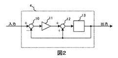
- the figure which shows the structure of LPF (low-pass filter) 4 The figure which shows arrangement
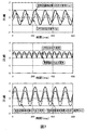
- the figure which shows the operation waveform of each part Diagram showing pulsation frequency dependence of correction amount The figure which shows the structure of the air flow measuring device of 2nd Example.
- the figure which shows the operation waveform of each part Diagram showing pulsation frequency dependence of correction amount The figure which shows the structure of the air flow measuring device of 3rd Example.
- the figure which shows the frequency characteristic of LPF40 Diagram showing pulsation frequency dependence of correction amount The figure which shows the structure of the air flow measuring device of 4th Example.
- the figure which shows the output waveform of the maximum value detector 33 and the minimum detector 34 The figure which shows Vsen-Vmax and Vsen-Vmin in various states
- the air flow rate measuring apparatus 1 of the present embodiment includes an air flow rate detector 2 that generates an output signal Vsen corresponding to the air flow rate to be measured, an amplitude detector 3 that detects a pulsation amplitude Vp from the output signal Vsen, and a pulsation amplitude Vp.
- a low-pass filter (hereinafter referred to as LPF) 4 whose cutoff frequency changes according to the value of, and a waveform calculator 5 that performs waveform calculation of the output signal Vlpf and output signal Vsen of the LPF 4.
- the waveform calculator 5 includes multipliers 6 and 7, an adder 8, and a condition determination process 9. As shown in FIG.
- the LPF 4 includes a subtracter 10, a multiplier 11, an adder 12, and a delay element 13.
- the cutoff frequency of the LPF 4 changes according to the pulsation amplitude Vp.
- the output signal Vsen of the air flow rate measuring device 1 has a pulsation error caused by pulsation, and this pulsation error is influenced by the average flow rate, pulsation amplitude, pulsation frequency, and the like.
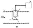
- the air flow rate measuring device 1 includes a bypass passage 16, a flow rate detector 2 disposed in the bypass passage 16, and a signal processing circuit 17 that processes a signal from the flow rate detector 2.
- An engine control unit 19 that receives a flow signal from the air flow measuring device 1 and performs various controls is disposed.
- the operation of the air flow rate measuring device 1 will be described with reference to FIGS.
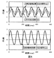
- the output signal Vsen of the air amount detector 2 has a pulsation waveform as shown in FIG. 4, the amplitude of the output signal Vlpf of the LPF 4 decreases according to the frequency of the output signal Vsen and the cutoff frequency of the LPF 4.
- the average value of the output signal Vout changes in the positive direction, and an error caused by the pulsation of the air flow rate detector 2 is corrected by the change in the positive direction, and the output of the air flow rate measuring device 1 is obtained.
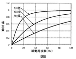
- the correction amount is determined by the pulsation frequency and the cut-off frequency fc of the LPF 4 as shown in FIG. 5, and when the cut-off frequency fc of the LPF 4 is increased, the correction amount is decreased. To increase.
- the correction amount is changed according to the pulsation amplitude Vp and the pulsation frequency.
- the inflow of air into the bypass passage 16 is accompanied by an increase in the pulsation frequency. Decrease. This occurs because the viscosity of air inside the bypass passage 16 is larger than the viscosity of air outside the bypass passage 16. In other words, when the pulsation amplitude increases, the inflow of air into the bypass passage 16 decreases as the pulsation frequency increases, and a negative error occurs in the output signal Vsen of the air amount detector 2.
- the air flow measurement device 1 of the present invention when the pulsation amplitude Vp is large, the pulsation error of the air flow measurement device 1 is reduced by increasing the correction amount in the positive direction according to the increase of the pulsation frequency. can do. That is, when the pulsation amplitude Vp is small, the cutoff frequency fc of the LPF 4 is increased to reduce the correction amount, and when the pulsation amplitude Vp is large, the cutoff frequency fc of the LPF 4 is decreased to increase the correction amount. Further, since this correction amount increases in the positive direction when the pulsation frequency increases, the pulsation error of the air amount detector 2 can be canceled out. Thereby, the pulsation error of the air flow rate measuring device 1 can be reduced.
- the pulsation frequency dependence of the pulsation error is corrected using the frequency characteristics of the LPF 4, so that the change in the pulsation state can be followed at high speed.
- the engine speed is required, it is necessary to arrange a processing circuit for correcting pulsation in the engine control unit 19 that can easily obtain the engine speed.
- the engine speed is not required, so that the pulsation correction can be performed on the air flow rate measuring device 1 side, and a highly accurate signal in which the pulsation error is corrected is transmitted to the engine control unit 19. It is possible.
- the LPF 4 calculates the vector sum of each frequency for a plurality of frequency signals, it works in the direction of reducing the pulsation error due to the influence of harmonics. For this reason, in the present invention, the pulsation error can be reduced even when a harmonic exists in the pulsation.
- FIGS. 6 shows the configuration of the air flow rate measuring apparatus according to the second embodiment
- FIG. 7 shows the operation waveform of each part
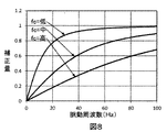
- FIG. 8 shows the pulsation frequency dependence of the correction amount.
- the air flow measuring device 20 of this embodiment includes an air flow detector 21 that generates an output signal Vsen corresponding to the air flow to be measured, an amplitude detector 22 that detects a pulsation amplitude Vp from the output signal Vsen, and a pulsation amplitude Vp.
- LPF 23 whose cut-off frequency changes according to the value
- waveform calculator 24 that calculates the waveform of output signal Vlpf and output signal Vsen of LPF 23, multiplier 28 that amplifies the output of waveform calculator 24, and multiplier 28 Of the output signal Vsen and the adder 30 for adding the outputs of the LPF 29.
- the waveform calculator 24 includes subtractors 25 and 26 and a condition determination process 27.
- the configuration of the LPF 23 is the same as that of the LPF 4 shown in the first embodiment, and the cut-off frequency changes according to the pulsation amplitude Vp.
- the output signal Vsen of the air amount detector 21 has a pulsation waveform as shown in FIG. 7, the amplitude of the output signal Vlpf of the LPF 23 decreases according to the frequency of the output signal Vsen and the cutoff frequency of the LPF 23.
- the output signal Vsen and the output signal Vlpf are waveform-calculated by the waveform calculator 24.
- the gain k of the multiplier 18 is 1, the output signal of the multiplier 28 is like a full-wave rectification as shown in FIG. Waveform.
- the output signal of the multiplier 28 is converted into a direct current by the LPF 29 and has a waveform shown in FIG.
- the output signal (correction signal) of the LPF 29 is added to the output signal Vsen of the air flow rate detector 21 by the adder 30 to obtain the output signal Vout of the air flow rate measuring device 20.
- the air flow measurement device in the second embodiment has basically the same configuration as the air flow measurement device in the first embodiment, but the following improvements have been made.
- the waveform calculator 24 outputs a waveform such as full-wave rectification to facilitate DC conversion in the LPF 29. Further, an LPF 29 is provided to make the correction signal DC. This limited the signal band of the correction signal.
- the waveform calculator 5 as used in the first embodiment is employed, there is no problem while the correction amount is small, but when the gain k is increased and the correction amount is increased, noise due to waveform computation increases. .
- the correction signal is converted into a direct current by the LPF 29, so that an increase in noise can be reduced.
- the correction amount is determined by the pulsation frequency and the cut-off frequency fc of the LPF 23 as shown in FIG. 8, and when the cut-off frequency fc of the LPF 23 is increased, the correction amount decreases.
- the cut-off frequency fc of the LPF 23 is lowered, the correction amount increases. That is, the pulsation amplitude Vp is detected from the output signal Vsen by the amplitude detector 22 and the cut-off frequency fc of the LPF 23 is changed according to the pulsation amplitude Vp, thereby changing the correction amount according to the pulsation amplitude Vp and the frequency. be able to.
- the air flow rate measuring device 20 of the present invention when the pulsation amplitude is large, a minus error occurs with the increase of the pulsation frequency. Therefore, by using the air flow rate measuring device 20 of the present invention, the pulsation is obtained. Since the correction amount can be increased according to the frequency, the pulsation error caused by the pulsation of the air flow rate measuring device 1 can be reduced.
- FIGS. 9 shows the configuration of the air flow rate measuring apparatus according to the third embodiment
- FIG. 10 shows the frequency characteristics of the LPF 40
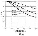
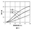
- FIG. 11 shows the pulsation frequency dependence of the correction amount.
- the air flow rate measuring device 31 of the present embodiment includes an air flow rate detector 32 that generates an output signal Vsen corresponding to the air flow rate to be measured, a maximum value detection circuit 33 that detects a maximum value from the output signal Vsen, and an output signal Vsen.
- the minimum value detection circuit 34 for detecting the minimum value the adder 35 for calculating the sum of the outputs of the maximum value detection circuit 33 and the minimum value detection circuit 34, and the output of the adder 35 is halved to determine the median value Med.
- LPF 40 whose cut-off frequency changes according to cut-off frequency fc applied, rectifier 41 for full-wave rectification of the output of LPF 40, rectifier 42 for full-wave rectification of the output of HPF 39, and outputs of rectifier 41 and rectifier 42
- the subtractor 43 for obtaining the difference between the two, the multiplier 44 for amplifying the output of the subtractor 43 by changing the amplification factor in accordance with the amplification factor Gain output from the two-dimensional map 38, and converting the output of the multiplier 44 to DC LPF 45, an adder 46 for adding the offset value Offset output from the two-dimensional map 38 to the output of the LPF 45, and an adder 47 for adding the output of the adder 46 to the output signal Vsen to obtain the output signal Vout.
- the configuration of the LPF 40 is the same as that of the LPF 4 shown in the first embodiment, and the cutoff frequency can be changed according to the cutoff frequency fc output from the two-dimensional map 38.
- the air flow measuring device in the third embodiment is basically the same structure as the air flow measuring device in the second embodiment, but the following improvements were added.
- a maximum value detection circuit 33 and a minimum value detection circuit 34 are provided, and the median value Med and amplitude Amp are obtained by calculating these outputs, and the median value Med and amplitude Amp are input.
- a two-dimensional map 38 is provided to output a cutoff frequency fc, an amplification factor Gain, and an offset value Offset.
- the cutoff frequency of the LPF 40 can be adjusted not only by the amplitude information of the output signal Vsen but also by the two types of information of the median value Med and the amplitude Amp as in the second embodiment.
- the correction amount can be controlled more freely by using the two-dimensional map 38.
- the input of the two-dimensional map 38 may be a value that represents the characteristics of the output signal Vsen, the average value, median value, amplitude, maximum value, minimum value, sum of the maximum value and minimum value of the output signal Vsen, Either the maximum value or the minimum value may be used.
- the cutoff frequency of the LPF 40 but also the gain Gain and the offset value Offset can be manipulated so that the correction amount can be controlled more freely. As a result, the pulsation error of the air flow measuring device 1 can be further reduced.
- the outputs of the LPF 40 and the HPF 39 are each subjected to full-wave rectification, and the difference between them is output.
- the LPF 40 has a frequency characteristic of 1 at a low frequency and decreases from 1 after a predetermined frequency. Accordingly, the subtractor 43 obtains the difference between the signal of the rectifier 41 obtained by full-wave rectifying the output signal of the LPF 40 from the signal of the rectifier 42 obtained by full-wave rectifying the output of the HPF 39, and the output characteristics of the subtractor 43 are as shown in FIG.
- the correction amount is zero at a low frequency, and the correction amount increases after a predetermined frequency.
- the frequency characteristic approximated by the frequency characteristic of the pulsation error can be realized, so that the pulsation error of the air flow rate measuring device 31 can be further reduced.
- the pulsation error can be further reduced when harmonics exist.
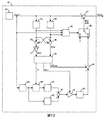
- FIGS. 12 shows the configuration of the air flow measuring device of the fourth embodiment
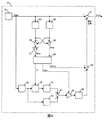
- FIG. 13 shows the configuration of the pulsation determination device 48
- FIG. 14 shows the output waveforms of the maximum value detector 33 and the minimum detector 34
- FIG. Vsen-Vmax and Vsen-Vmin shows the configuration of the maximum value detector 33 and the minimum detector 34.
- the air flow rate measuring device of the fourth embodiment is basically the same structure as the sensor device of the third embodiment, but the following improvements have been made.
- a pulsation determination unit 48 is added, and when the pulsation state is not established, the correction signal is set to 0 by the switch 49.
- the pulsation determiner 48 includes a subtractor 50 for obtaining a difference between the output signal Vsen and the output Vmax of the maximum value detector 33, a hold circuit 51 for holding the output of the subtractor 50 for a certain time, A comparator 52 for determining whether the output of the circuit 51 is larger or smaller than a predetermined value, a subtractor 54 for obtaining a difference between the output signal Vsen and the output Vmin of the minimum value detector 34, and a constant output of the subtractor 54 It comprises a hold circuit 55 that holds time, a comparator 56 that determines whether the output of the hold circuit 55 is larger or smaller than a predetermined value, and a logical sum circuit 53 that obtains the logical sum of the comparator 52 and the comparator 56.
- the pulsation determiner 48 includes a subtractor 50 for obtaining a difference between the output signal Vsen and the output Vmax of the maximum value detector 33, a hold circuit 51 for holding the output of the subtractor 50 for a certain time, A comparator 52 for
- the outputs of the maximum value detector 33 and the minimum value detector 34 change as shown in FIG.
- the maximum value detector 33 rises quickly but falls slowly.
- the minimum value detector 34 falls early but rises slowly.
- the maximum value detector 33 and the minimum value detector 34 cause an operation delay with respect to the amplitude change of the output signal Vsen.
- an unnecessary signal may be output in an air flow transient state.
- a pulsation determination unit 48 is added in this embodiment, and the correction signal is set to 0 by the switching unit 49 when not in a pulsation state.
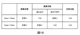
- FIG. 15 shows Vsen-Vmax and Vsen-Vmin in various states.
- both Vsen ⁇ Vmax and Vsen ⁇ Vmin are large.
- only one of Vsen ⁇ Vmax and Vsen ⁇ Vmin increases in the transient state.
- both Vsen ⁇ Vmax and Vsen ⁇ Vmin are almost zero. Utilizing this fact, the pulsation determination unit 48 determines the pulsation state.
- FIG. 16 shows the configuration of the air flow measuring device of the fifth embodiment.
- the sensor device of the fifth embodiment has basically the same structure as the sensor device of the third embodiment, but has the following improvements.
- the steady state determination unit 54 is added, and the LPF 55 is added to the signal path of the output signal Vout by the switching unit 56 in the steady state.
- the steady state determination unit 54 has basically the same structure as the pulsation determination unit 48 described above, but it is used that both Vsen-Vmax and Vsen-Vmin are almost zero in the steady state as shown in FIG. Is determined to be in a steady state.
- the steady state determination unit 54 determines that the steady state is present, and in the steady state, the LPF 55 is added to the signal path of the output signal Vout, thereby reducing the noise of the output signal Vout in the steady state. I was able to do it. Further, since the steady state determination unit 54 does not operate in the transient state, the LPF 55 is not added to the signal path of the output signal Vout. For this reason, the noise of the output signal Vout in the steady state can be reduced without impairing the responsiveness in the transient state.
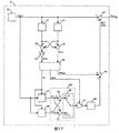
- FIG. 17 shows the configuration of the air flow rate measuring apparatus according to the sixth embodiment
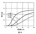
- FIG. 18 shows the pulsation frequency dependence of the correction amount.
- the sensor device of the sixth embodiment has basically the same structure as the sensor device of the third embodiment, but has the following improvements.
- the secondary LPF 57 and the primary all-pass filter 58 are arranged, and the waveform calculator 59 calculates the waveform of the outputs of the secondary LPF 57 and the primary all-pass filter 58.
- the waveform calculator 59 includes subtracters 60 and 61 and a condition determination process 62.
- the cutoff frequency of the secondary LPF 57 and the time constant of the primary all-pass filter 58 are changed at a constant ratio, the output waveform of the secondary LPF 57 and the output waveform of the primary all-pass filter 58 are the same at low frequencies. Therefore, as shown in FIG. 18, it is possible to obtain a characteristic that the correction amount increases rapidly when the correction amount at low frequency is 0 and the predetermined frequency is exceeded. In addition, the pulsation error hardly occurs at low frequency, and the error tends to increase from a specific frequency. By using the air flow measuring device of this embodiment, the frequency characteristic approximated by the frequency characteristic of the pulsation error is realized. Therefore, the pulsation error of the air flow rate measuring device 31 can be further reduced.
- the engine control unit 19 is provided with the pulsation correction processing circuit 64 detailed in each embodiment.
- the output signal Vsen detected by the flow rate detector 65 of the air flow rate measuring device 63 may be input to the engine control unit 19 and pulsation correction may be performed on the engine control unit 19 side.
- Detecting element 19 engine control unit, 20 air flow measuring device, 21 air flow detector, 22 amplitude detector, 23 LPF, 24 waveform calculator, 25 subtractor, 26 subtractor, 27 ⁇ Condition determination processing, 28 ⁇ Multiplier, 29 ⁇ LPF, 30 ⁇ Adder, 31 ⁇ Air flow measurement device ⁇ 32 ⁇ Air flow detector ⁇ 33 ⁇ Maximum value detection circuit ⁇ 34 ⁇ Minimum value detection circuit ⁇ 35 ⁇ Addition 36, subtractor, 37, multiplier, 38 2-dimensional map, 39 HPF (high pass filter), 40 LPF, 41 rectifier, 42 rectifier, 43 subtractor, 44 multiplier, 45 LPF, 46 adder, 47 adder, 48. Pulsation judging device, 49 ... Switcher, 50 ... Subtractor, 51 ...
- Hold circuit, 52 ... Comparator, 53 ... OR circuit, 54 ... Subtractor, 55 ... Hold circuit, 56 ... Comparator, 57 ... Secondary LPF , 58... Primary all pass filter, 59... Waveform calculator, 60. Subtracter, 61.
Landscapes
- Physics & Mathematics (AREA)
- Fluid Mechanics (AREA)
- General Physics & Mathematics (AREA)
- Measuring Volume Flow (AREA)
- Electromagnetism (AREA)
Abstract
従来の空気流量測定装置では脈動誤差の補正に高速フーリエ変換を使用するため、高速フーリエ変換に必要な観測時間と演算時間の為に補正が遅れ、脈動状態の変化に高速に追従することが困難であった。 本発明による空気流量測定装置は測定する空気流量に応じた出力信号Vsenを発生させる空気流量検出器2と、出力信号Vsenから脈動振幅Vpを検出する振幅検出器3と、脈動振幅Vpの値に応じてカットオフ周波数の変化するLPF4と、LPF4の出力信号Vlpfと出力信号Vsenの波形演算をする波形演算器5とで構成される。なお、波形演算器5は乗算器6、7と加算器8と条件判定処理9から構成される。また、LPF4は減算器10、乗算器11、加算器12、遅延素子13により構成され、乗算器11のゲインを脈動振幅Vpにより変化させることでカットオフ周波数が脈動振幅Vpに応じて変化する
Description
本発明は空気流量検出器の出力信号に応じて空気流量信号を出力する空気流量測定装置に係り、特に、脈動によって生じる脈動誤差を低減できる空気流量測定装置に関する。
空気流量測定装置において脈動誤差を低減する方法として、例えば特許文献1に記載された方法がある。特許文献1によれば、空気流量検出器からの信号に基づいて平均処理部で平均値を求め、高周波分析部では高速フーリエ変換を用いて周波数と脈動振幅を求め、これらから得られた平均値、周波数、脈動振幅から補正量を算出し、空気流量検出器からの信号の脈動によって生じる脈動誤差を補正している。
特許文献1の技術では高周波分析部に高速フーリエ変換を使用している。高速フーリエ変換において、所望の周波数分析範囲と分解能を得ようとすると、所定の長さの観測時間とサンプリング周波数を必要とし、演算量も周波数分析範囲と分解能に応じて指数的に増加する。この為、高速フーリエ変換の結果が出力されるまでには所定の観測時間と所定の演算時間を必要とするので補正量の算出までに長時間を要してしまい脈動状態の変化に追従できない。つまり、特許文献1の技術では、脈動状態の変化に対して検討の余地が残されている。
本発明は上記事情に鑑みてなされたものであり,その目的は、脈動状態の変化に高速に追従できる脈動誤差補正処理を有する空気流量測定装置を提供することにある。
上記課題を解決するためには、前記空気流量検出器の出力信号の代表値に応じて特性の変化するフィルタの出力信号を波形演算し、波形演算した出力に基づいて空気流量信号を出力することにより達成される。
本発明によれば、脈動状態の変化に高速に追従できる脈動誤差補正処理を有する空気流量測定装置を提供することが可能となる。
以下,本発明の実施の形態について,図面を参照して説明する。
まず,本発明の第1の実施例である空気流量測定装置を図1から図5を用いて説明する。
本実施例の空気流量測定装置1は、測定する空気流量に応じた出力信号Vsenを発生させる空気流量検出器2と、出力信号Vsenから脈動振幅Vpを検出する振幅検出器3と、脈動振幅Vpの値に応じてカットオフ周波数が変化するローパスフィルタ(以下、LPF)4と、LPF4の出力信号Vlpfと出力信号Vsenの波形演算をする波形演算器5と、を備える。波形演算器5は、乗算器6、7と、加算器8と、条件判定処理9を備える。また、図2に示す様に、LPF4は減算器10と、乗算器11と、加算器12と、遅延素子13とを備えている。乗算器11のゲインを脈動振幅Vpにより変化させることで、LPF4のカットオフ周波数が脈動振幅Vpに応じて変化する。なお、空気流量測定装置1の出力信号Vsenには脈動によって生じる脈動誤差があり、この脈動誤差は平均流量、脈動振幅、脈動周波数などに影響される。
次に、図3を用いて、空気流量測定装置1の吸気管への配置を説明する。吸気管14には空気流が流入し、この吸気管14に空気流量測定装置1が取り付けられている。空気流量測定装置1は、バイパス通路16と、バイパス通路16内に配置された流量検出器2と、流量検出器2からの信号を処理する信号処理回路17から構成される。また、空気流量測定装置1からの流量信号を受け取り、各種制御を行うエンジン制御ユニット19が配置される。
次に、図4,5を用い空気流量測定装置1の動作を説明する。空気量検出器2の出力信号Vsenが、図4に示すような脈動波形となる場合、LPF4の出力信号Vlpfは出力信号Vsenの周波数とLPF4のカットオフ周波数に応じて振幅が減少する。ここで、出力信号Vsenと出力信号Vlpfは波形演算器5により波形演算され、k=1の場合には図4に示す空気流量測定装置1の出力信号Voutになり、波形の上半分が間延びした様な波形になる。この結果、出力信号Voutの平均値はプラス方向に変化し、このプラス方向の変化により空気流量検出器2の脈動による誤差を補正して空気流量測定装置1の出力を得る。この時、補正量は図5に示す様に脈動周波数とLPF4のカットオフ周波数fcで決まり、LPF4のカットオフ周波数fcを高くすると補正量は減り、LPF4のカットオフ周波数fcを低くすると補正量は増加する。つまり、出力信号Vsenから脈動振幅Vpを振幅検出器3で検出し、脈動振幅Vpに応じてLPF4のカットオフ周波数fcを変化させることで、脈動振幅Vpと脈動周波数に応じて、補正量を変化させることができる。
また、バイパス通路16を持つ空気流量測定装置では、脈動振幅が大きくなると(特に、脈動振幅が平均値の4倍以上ある場合)、バイパス通路16への空気の流入は脈動周波数の増加と伴に減少する。これは、バイパス通路16内部での空気の粘性が、バイパス通路16の外部での空気の粘性に比べて大きいために生じる。つまり、脈動振幅が大きくなると、脈動周波数の増加に伴いバイパス通路16への空気の流入は減少し、空気量検出器2の出力信号Vsenにマイナス誤差が生じる。従って、本発明の空気流量測定装置1を用いることで、脈動振幅Vpが大きい場合に脈動周波数の増加に応じてプラス方向への補正量を増加させることで空気流量測定装置1の脈動誤差を低減することができる。つまり、脈動振幅Vpが小さい場合にはLPF4のカットオフ周波数fcを高くして補正量を小さくし、脈動振幅Vpが大きい場合にはLPF4のカットオフ周波数fcを低くして補正量を大きくする。また、この補正量は脈動周波数が高くなるとプラス方向に増加するので、空気量検出器2の脈動誤差を打ち消すことができる。このことにより、空気流量測定装置1の脈動誤差を低減できる。
また、本発明の空気流量測定装置1ではLPF4の周波数特性を用いて、脈動誤差の脈動周波数依存性を補正するので、脈動状態の変化に対して高速に追従することができる。
従来例ではエンジン回転数を必要としたので、エンジン回転数を容易に得られるエンジン制御ユニット19に脈動補正をする処理回路を配置する必要があった。一方で、本発明では従来例の様にエンジン回転数を必要としないので、空気流量測定装置1側で脈動補正が可能となり、脈動誤差を補正した精度の高い信号をエンジン制御ユニット19に送信することが可能である。
また、LPF4は複数の周波数信号に対して各周波数のベクトル和を求めるので、高調波の影響による脈動誤差を低減する方向に働く。この為、本発明では脈動に高調波が存在した場合にも脈動誤差を低減できる。
次に,本発明の第2の実施例である空気流量測定装置を図6から図8により説明する。なお,図6は第2の実施例の空気流量測定装置の構成、図7は各部の動作波形、図8は補正量の脈動周波数依存性である。
本実施例の空気流量測定装置20は測定する空気流量に応じた出力信号Vsenを発生させる空気流量検出器21と、出力信号Vsenから脈動振幅Vpを検出する振幅検出器22と、脈動振幅Vpの値に応じてカットオフ周波数の変化するLPF23と、LPF23の出力信号Vlpfと出力信号Vsenの波形演算をする波形演算器24と、波形演算器24の出力を増幅する乗算器28と、乗算器28の出力を直流化するLPF29と、出力信号VsenとLPF29の出力を加算する加算器30とで構成される。なお、波形演算器24は減算器25、26と条件判定処理27から構成される。なお、LPF23の構成は第1の実施例で示したLPF4と同一の構成でカットオフ周波数が脈動振幅Vpに応じて変化する。
次に、図7,8を用い空気流量測定装置1の動作を説明する。空気量検出器21の出力信号Vsenが図7に示すような脈動波形となる場合、LPF23の出力信号Vlpfは出力信号Vsenの周波数とLPF23のカットオフ周波数に応じて振幅が減少する。ここで、出力信号Vsenと出力信号Vlpfは波形演算器24により波形演算され、乗算器18のゲインkが1の場合には乗算器28の出力信号は図7に示す様な全波整流の様な波形になる。乗算器28の出力信号はLPF29により直流化され図7に示す波形になる。このLPF29の出力信号(補正信号)は加算器30で空気流量検出器21の出力信号Vsenと加算され、空気流量測定装置20の出力信号Voutを得る。
第2の実施例における空気流量測定装置は第1の実施例における空気流量測定装置と基本的に同じ構成であるが、以下の改良を加えた。第2の実施例における空気流量測定装置では波形演算器24で全波整流の様な波形を出力させ、LPF29における直流化を容易にした。また、LPF29を設けて補正信号を直流化した。このことで、補正信号の信号帯域を制限した。第1の実施例で採用した様な波形演算器5を採用した場合、補正量が小さい間は問題ないが、ゲインkを大きくして補正量を大きくした場合には波形演算によるノイズが大きくなる。これに対して、本実施例では補正信号をLPF29で直流化するのでノイズの増加を低減できる。
本実施例においても、第1の実施例と同様に補正量は図8に示す様に脈動の周波数とLPF23のカットオフ周波数fcで決まり、LPF23のカットオフ周波数fcを高くすると補正量は減り、LPF23のカットオフ周波数fcを低くすると補正量は増加する。つまり、出力信号Vsenから脈動振幅Vpを振幅検出器22で検出し、脈動振幅Vpに応じてLPF23のカットオフ周波数fcを変化させることで、脈動振幅Vpと周波数に応じて、補正量を変化させることができる。また、先に説明したようにバイパス通路を持つ空気流量検出器では、脈動振幅が大きい場合、脈動周波数の増加に伴いマイナス誤差が生じるので、本発明の空気流量測定装置20を用いることで、脈動周波数に応じて補正量を増加させられるので、空気流量測定装置1の脈動によって生じる脈動誤差を低減することができる。
次に,本発明の第3の実施例である空気流量測定装置を図9から図11により説明する。なお,図9は第3の実施例の空気流量測定装置の構成、図10はLPF40の周波数特性、図11は補正量の脈動周波数依存性である。
本実施例の空気流量測定装置31は測定する空気流量に応じた出力信号Vsenを発生させる空気流量検出器32と、出力信号Vsenから最大値を検出する最大値検出回路33と、出力信号Vsenから最小値を検出する最小値検出回路34と、最大値検出回路33と最小値検出回路34の出力の和を求める加算器35と、加算器35の出力を1/2にして中央値Medを求める乗算器37と、最大値検出回路33と最小値検出回路34の出力の差を演算して振幅Ampを求める減算器36と、中央値Medと振幅Ampを入力としてカットオフ周波数fcと増幅率Gainとオフセット値Offsetを出力する2次元マップ38と、出力信号Vsenの直流成分を除去するHPF(ハイパスフィルタ)39と、2次元マップ38から出力されるカットオフ周波数fcに応じてカットオフ周波数の変化するLPF40と、LPF40の出力を全波整流する整流器41と、HPF39の出力を全波整流する整流器42と、整流器41と整流器42の出力の差を求める減算器43と、2次元マップ38から出力される増幅率Gainに応じて増幅率を変化させて減算器43の出力を増幅する乗算器44と、乗算器44の出力を直流化するLPF45と、LPF45の出力に2次元マップ38から出力されるオフセット値Offsetを加算する加算器46と、加算器46の出力を出力信号Vsenに加算し出力信号Voutを求める加算器47から構成される。なお、LPF40の構成は第1の実施例で示したLPF4と同一の構成でカットオフ周波数を2次元マップ38から出力されるカットオフ周波数fcに応じて変化させることができる。
第3の実施例における空気流量測定装置は第2の実施例における空気流量測定装置と基本的に同じ構造であるが、以下の改良を加えた。第3の実施例における空気流量測定装置では最大値検出回路33と最小値検出回路34を設け、これらの出力を演算することで中央値Medと振幅Amp求め、中央値Medと振幅Ampを入力する2次元マップ38を設けカットオフ周波数fcと増幅率Gainとオフセット値Offsetを出力した。このことにより、第2の実施例の様に出力信号Vsenの振幅情報だけでは無く中央値Medと振幅Ampの2種類の情報でLPF40のカットオフ周波数を調整できるようにした。また、2次元マップ38を用いることでより自由に補正量を制御できるようにした。なお、2次元マップ38の入力は出力信号Vsenの特徴を代表する値であれば良いので、出力信号Vsenの平均値、中央値、振幅、最大値、最小値、最大値と最小値の和、最大値と最小値の差のいずれでも良い。また、本実施例ではLPF40のカットオフ周波数だけでは無く、増幅率Gainとオフセット値Offsetも操作できる様にしてより自由に補正量を制御できるようにした。このことにより空気流量測定装置1の脈動誤差をより低減することができる。
また、脈動による誤差は低周波数ではほとんど生じず、特定の周波数から誤差が増加する傾向がある。これに対応するため本実施例ではLPF40とHPF39の出力を各々全波整流し、これらの差分を出力する構成にした。LPF40の周波数特性は図10に示す様に低周波ではゲインが1で所定の周波数を過ぎるとゲインが1から小さくなる。従って、HPF39の出力を全波整流した整流器42の信号からLPF40の出力信号を全波整流した整流器41の信号の差を減算器43で求めることで、減算器43の出力特性は図11の様な周波数特性になり、低周波では補正量が0で所定の周波数を過ぎると補正量が増加する。このことにより、脈動誤差の周波数特性により近似した周波数特性を実現することができるので、空気流量測定装置31の脈動誤差をより低減することができる。
また、第2の実施例同様に、高調波が存在した場合にも脈動誤差をより低減できる。
次に,本発明の第4の実施例である空気流量測定装置を図12から図15により説明する。なお,図12は第4の実施例の空気流量測定装置の構成、図13は脈動判定器48の構成、図14は最大値検出器33と最小検出器34の出力波形、図15は各種状態でのVsen-VmaxおよびVsen-Vminである。
第4の実施例の空気流量測定装置は第3の実施例のセンサ装置と基本的に同じ構造であるが、以下の改良を加えた。本実施例では脈動判定器48を付加し、脈動状態で無い時には切替え器49により補正信号を0にした。
図13に示すように、脈動判定器48は、出力信号Vsenと最大値検出器33の出力Vmaxの差を求める減算器50と、減算器50の出力を一定時間ホールドするホールド回路51と、ホールド回路51の出力が所定の値よりも大きいか小さいかを判定する比較器52と、出力信号Vsenと最小値検出器34の出力Vminの差を求める減算器54と、減算器54の出力を一定時間ホールドするホールド回路55と、ホールド回路55の出力が所定の値よりも大きいか小さいかを判定する比較器56と、比較器52と比較器56の論理和を求める論理和回路53より構成される。
出力信号Vsenの脈動振幅が変化した場合、図14に示すように最大値検出器33および最小値検出器34の出力は変化する。ここで、最大値検出器33の立ち上がりは早いが立下りは遅い。これに対して最小値検出器34の立ち下がりは早いが立ち上がりは遅い。この動作により、出力信号Vsenの振幅変化に対して最大値検出器33および最小値検出器34は動作遅延を起こす。この結果、空気流の過渡状態において不必要な信号を出力する恐れが生じる。これを防ぐ為に本実施例では脈動判定器48を付加し、脈動状態で無い時には切替え器49により補正信号を0にした。
図15に各種状態でのVsen-VmaxおよびVsen-Vminを示す。脈動状態ではVsen-VmaxおよびVsen-Vmin共に大きい。これに対して、過渡状態ではVsen-VmaxもしくはVsen-Vminの一方だけが大きくなる。また、定常状態ではVsen-VmaxおよびVsen-Vmin共にほぼ0になる。このことを利用して脈動判定器48では脈動状態を判定する。つまり、Vsen-VmaxおよびVsen-Vmin共に大きい時を脈動状態と判定し、それ以外を脈動状態ではないと判定し、脈動状態で無い時には補正信号を0にすることで、最大値検出器33および最小値検出器34の動作遅延によって生じる可能性のある不必要な補正を無くすことができる。
次に,本発明の第5の実施例である空気流量測定装置を図16により説明する。なお,図16は第5の実施例の空気流量測定装置の構成である。第5の実施例のセンサ装置は第3の実施例のセンサ装置と基本的に同じ構造であるが、以下の改良を加えた。本実施例では定常状態判定器54を付加し、定常状態の時には切替え器56により出力信号Voutの信号経路にLPF55を付加するようにした。定常状態判定器54は先に示した脈動判定器48と基本的には同じ構造であるが、図15に示す様に定常状態ではVsen-VmaxおよびVsen-Vmin共にほぼ0になることを利用して定常状態であることを判定している。
本実施例では、定常状態であることを定常状態判定器54で判定し、定常状態の場合にはLPF55を出力信号Voutの信号経路に付加することで、定常状態における出力信号Voutのノイズを低減できるようにした。また、過渡状態では定常状態判定器54は動作しないのでLPF55は出力信号Voutの信号経路に付加されない。この為、過渡状態における応答性を損なわずに定常状態における出力信号Voutのノイズを低減できる。
次に,本発明の第6の実施例である空気流量測定装置を図17,18により説明する。なお,図17は第6の実施例の空気流量測定装置の構成、図18は補正量の脈動周波数依存性である。第6の実施例のセンサ装置は第3の実施例のセンサ装置と基本的に同じ構造であるが、以下の改良を加えた。
本実施例では2次LPF57と、1次オールパスフィルタ58を配置し、2次LPF57と1次オールパスフィルタ58の出力を波形演算器59で波形演算した。なお、波形演算器59は減算器60,61と条件判定処理62で構成される。
2次LPF57のカットオフ周波数と1次オールパスフィルタ58の時定数を一定の比率で変化させた場合、低周波では2次LPF57の出力波形と1次オールパスフィルタ58の出力波形は同一になる。この為、図18に示す様に低周波数での補正量が0で所定の周波数を過ぎると補正量が急激に増加する特性を得ることができる。また、脈動誤差は低周波数ではほとんど生じず、特定の周波数から誤差が増加する傾向があり、本実施例の空気流量測定装置を使用することで、脈動誤差の周波数特性により近似した周波数特性を実現することができるので、空気流量測定装置31の脈動誤差をより低減することができる。
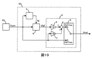
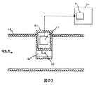
本発明の各実施形態における変形例を図19、図20を用いて説明する。
図19、図20に示すように、エンジン制御ユニット19に各実施例で詳述した脈動補正処理回路64を配置している。空気流量測定装置63の流量検出器65で検出した出力信号Vsenをエンジン制御ユニット19に入力し、エンジン制御ユニット19側で脈動補正をしてもよい。
1‥空気流量測定装置,2‥空気流量検出器,3‥振幅検出器,4‥LPF(ローパスフィルタ),5‥波形演算器,6‥乗算器,7‥乗算器,8‥加算器,9‥条件判定処理,10‥減算器,11‥乗算器,12‥加算器、13‥遅延素子,14‥吸気管,15‥空気流量センサ,16‥バイパス通路、17‥信号処理回路,18‥流量検出素子,19‥エンジン制御ユニット、20‥空気流量測定装置,21‥空気流量検出器、22‥振幅検出器,23‥LPF,24‥波形演算器,25‥減算器,26‥減算器,27‥条件判定処理,28‥乗算器,29‥LPF、30‥加算器,31‥空気流量測定装置、32‥空気流量検出器,33‥最大値検出回路,34‥最小値検出回路,35‥加算器,36‥減算器,37‥乗算器,38‥2次元マップ,39‥HPF(ハイパスフィルタ)、40‥LPF,41‥整流器、42‥整流器,43‥減算器,44‥乗算器,45‥LPF,46‥加算器,47‥加算器,48‥脈動判定器,49‥切替え器、50‥減算器,51‥ホールド回路、52‥比較器,53‥論理和回路,54‥減算器,55‥ホールド回路,56‥比較器,57‥2次LPF,58‥1次オールパスフィルタ,59‥波形演算器,60‥減算器,61‥減算器,62‥条件判定処理
Claims (9)
- 空気流量検出器と、
前記空気流量検出器の出力信号に基づき特性の変化するフィルタと、を備え、
前記空気流量検出器の出力と、前記フィルタを介した出力と、に基づいて空気流量信号を出力する空気流量測定装置 - 前記フィルタを介した出力を波形演算する波形演算部と、
前記波形演算部を介した出力と前記空気流量検出器の出力を加算する加算部と、を備える請求項1に記載の空気流量測定装置 - 前記フィルタは複数あり、
前記波形演算手段は、
前記複数のフィルタからの信号が入力されており、
前記複数の入力された信号の波形演算をする請求項2に記載の空気流量測定装置 - 前記フィルタは、前記空気流量検出器の出力信号の平均値、中央値、振幅、最大値、最小値、最大値と最小値の和、最大値と最小値の差のいずれかに応じて特性が変化する請求項1に記載の空気流量測定装置
- 前記空気流量検出器の出力信号の平均値、中央値、振幅、最大値、最小値、最大値と最小値の和、最大値と最小値の差のいずれかを検出する代表値検出手段と、
前記代表値検出手段の検出結果に応じた前記フィルタの特性を調整する調整量を出力するマップと、を備える請求項4に記載の空気流量測定装置 - 前記フィルタは、前記空気流量検出器の出力信号の脈動振幅に応じてカットオフ周波数を変化させている請求項1に記載の空気流量測定装置
- 前記空気流量検出器の出力信号の最大値を検出する最大値検出器と、
前記空気流量検出器の出力信号の最小値を検出する最小値検出器と、を備え、
前記空気流量検出器の出力信号と前記最大値検出器の出力信号の差が所定の値よりも大きく、且つ、前記空気流量検出器の出力信号と前記最小値検出器の出力信号の差が所定の値よりも大きい場合には、前記出力装置の出力信号を前記空気流量検出器の出力信号と同一にする請求項1に記載の空気流量測定装置 - 前記空気流量検出器の出力信号の最大値を検出する最大値検出器と、
前記空気流量検出器の出力信号の最小値を検出する最小値検出器と、を備え、
前記空気流量検出器の出力信号と前記最大値検出器の出力信号の差が所定の値よりも小さく、且つ、前記空気流量検出器の出力信号と前記最小値検出器の出力信号の差が所定の値よりも小さい場合には前記出力装置の出力信号にローパスフィルタ処理を施すことを特徴とする空気流量測定装置 - 前記フィルタは、前記空気流量検出器の出力信号の複数の周波数信号に対して各周波数の補正量のベクトル和を求める請求項2に記載の空気流量測定装置
Priority Applications (3)
| Application Number | Priority Date | Filing Date | Title |
|---|---|---|---|
| CN201680058919.3A CN108351235B (zh) | 2015-11-13 | 2016-10-17 | 空气流量测定装置 |
| US15/767,526 US20180299309A1 (en) | 2015-11-13 | 2016-10-17 | Air Flow Rate Measuring Device |
| DE112016004280.9T DE112016004280T5 (de) | 2015-11-13 | 2016-10-17 | Luftdurchflussmengen-Messvorrichtung |
Applications Claiming Priority (2)
| Application Number | Priority Date | Filing Date | Title |
|---|---|---|---|
| JP2015222588A JP6506681B2 (ja) | 2015-11-13 | 2015-11-13 | 空気流量測定装置 |
| JP2015-222588 | 2015-11-13 |
Publications (1)
| Publication Number | Publication Date |
|---|---|
| WO2017081987A1 true WO2017081987A1 (ja) | 2017-05-18 |
Family
ID=58695108
Family Applications (1)
| Application Number | Title | Priority Date | Filing Date |
|---|---|---|---|
| PCT/JP2016/080639 Ceased WO2017081987A1 (ja) | 2015-11-13 | 2016-10-17 | 空気流量測定装置 |
Country Status (5)
| Country | Link |
|---|---|
| US (1) | US20180299309A1 (ja) |
| JP (1) | JP6506681B2 (ja) |
| CN (1) | CN108351235B (ja) |
| DE (1) | DE112016004280T5 (ja) |
| WO (1) | WO2017081987A1 (ja) |
Cited By (3)
| Publication number | Priority date | Publication date | Assignee | Title |
|---|---|---|---|---|
| JP2018179811A (ja) * | 2017-04-14 | 2018-11-15 | 株式会社デンソー | 空気流量測定装置 |
| CN113039412A (zh) * | 2018-11-30 | 2021-06-25 | 日立安斯泰莫株式会社 | 物理量测定装置 |
| WO2021187357A1 (ja) * | 2020-03-17 | 2021-09-23 | 株式会社デンソー | 計測制御装置 |
Families Citing this family (7)
| Publication number | Priority date | Publication date | Assignee | Title |
|---|---|---|---|---|
| JP6763823B2 (ja) * | 2017-06-05 | 2020-09-30 | 日立オートモティブシステムズ株式会社 | 空気流量計 |
| JP2019086439A (ja) * | 2017-11-08 | 2019-06-06 | 株式会社デンソー | 空気流量計測装置、及び空気流量計測システム |
| DE112019003406T9 (de) * | 2018-07-05 | 2021-05-12 | Denso Corporation | Messsteuerungsvorrichtung und Strömungsvolumenmessvorrichtung |
| WO2020066548A1 (ja) * | 2018-09-26 | 2020-04-02 | 日立オートモティブシステムズ株式会社 | 内燃機関制御装置 |
| JP7237721B2 (ja) * | 2019-05-14 | 2023-03-13 | 日立Astemo株式会社 | 空気流量計 |
| WO2022130719A1 (ja) * | 2020-12-16 | 2022-06-23 | 日立Astemo株式会社 | 電子制御装置及び流量測定システム |
| JP7522070B2 (ja) * | 2021-04-16 | 2024-07-24 | トヨタ自動車株式会社 | データ処理方法 |
Citations (2)
| Publication number | Priority date | Publication date | Assignee | Title |
|---|---|---|---|---|
| US7286925B2 (en) * | 2004-10-01 | 2007-10-23 | Robert Bosch Gmbh | Method for pulsation correction within a measuring device measuring a media mass flow |
| JP5073949B2 (ja) * | 2006-02-02 | 2012-11-14 | 日立オートモティブシステムズ株式会社 | 流量測定装置 |
Family Cites Families (20)
| Publication number | Priority date | Publication date | Assignee | Title |
|---|---|---|---|---|
| US50155A (en) * | 1865-09-26 | Improvement in hydrants | ||
| JPS5917371B2 (ja) * | 1979-03-16 | 1984-04-20 | 日産自動車株式会社 | 流量検出装置 |
| US5435180A (en) * | 1992-10-07 | 1995-07-25 | Hitachi, Ltd. | Method and system for measuring air flow rate |
| JP3060861B2 (ja) * | 1994-11-18 | 2000-07-10 | 株式会社日立製作所 | 内燃機関の吸入空気量測定装置 |
| JP3200005B2 (ja) * | 1996-02-29 | 2001-08-20 | 株式会社日立製作所 | 発熱抵抗式空気流量測定装置 |
| JP3343509B2 (ja) * | 1998-05-06 | 2002-11-11 | 株式会社日立製作所 | 空気流量計測装置 |
| JP3421245B2 (ja) * | 1998-05-27 | 2003-06-30 | 株式会社日立製作所 | 発熱抵抗体式空気流量測定装置 |
| JP3679938B2 (ja) * | 1998-12-01 | 2005-08-03 | 株式会社日立製作所 | 内燃機関用発熱抵抗体式エアフローメータの信号処理方法 |
| JP3627564B2 (ja) * | 1999-03-15 | 2005-03-09 | 株式会社日立製作所 | 吸入空気流量計測装置 |
| JP3350501B2 (ja) * | 2000-01-26 | 2002-11-25 | 独立行政法人産業技術総合研究所 | 流量測定装置 |
| JP3752962B2 (ja) * | 2000-05-15 | 2006-03-08 | 株式会社日立製作所 | 熱式空気流量測定装置及びそれを用いた内燃機関並びに熱式空気流量測定方法 |
| DE10133524A1 (de) * | 2001-07-11 | 2003-01-30 | Bosch Gmbh Robert | Verfahren und Vorrichtung zur Korrektur des Dynamikfehlers eines Sensors |
| JP4130877B2 (ja) * | 2002-06-19 | 2008-08-06 | 株式会社日立製作所 | 流量計及び流量計システム |
| JP2005140689A (ja) * | 2003-11-07 | 2005-06-02 | Mitsubishi Electric Corp | 感熱式流量計および燃料制御装置 |
| CN101057126B (zh) * | 2004-11-11 | 2010-10-06 | 株式会社日立制作所 | 热式流量测定装置 |
| JP2006242748A (ja) * | 2005-03-03 | 2006-09-14 | Hitachi Ltd | 発熱抵抗体式空気流量測定装置およびその計測誤差補正方法 |
| JP5284864B2 (ja) * | 2009-04-30 | 2013-09-11 | 日立オートモティブシステムズ株式会社 | 熱式空気流量計 |
| JP5494435B2 (ja) * | 2010-11-22 | 2014-05-14 | 株式会社デンソー | 空気流量測定装置 |
| JP5681072B2 (ja) * | 2011-09-06 | 2015-03-04 | 日立オートモティブシステムズ株式会社 | 空気流量測定装置 |
| JP5615872B2 (ja) * | 2012-06-12 | 2014-10-29 | 日立オートモティブシステムズ株式会社 | 内燃機関の制御装置 |
-
2015
- 2015-11-13 JP JP2015222588A patent/JP6506681B2/ja active Active
-
2016
- 2016-10-17 US US15/767,526 patent/US20180299309A1/en not_active Abandoned
- 2016-10-17 CN CN201680058919.3A patent/CN108351235B/zh active Active
- 2016-10-17 WO PCT/JP2016/080639 patent/WO2017081987A1/ja not_active Ceased
- 2016-10-17 DE DE112016004280.9T patent/DE112016004280T5/de active Pending
Patent Citations (2)
| Publication number | Priority date | Publication date | Assignee | Title |
|---|---|---|---|---|
| US7286925B2 (en) * | 2004-10-01 | 2007-10-23 | Robert Bosch Gmbh | Method for pulsation correction within a measuring device measuring a media mass flow |
| JP5073949B2 (ja) * | 2006-02-02 | 2012-11-14 | 日立オートモティブシステムズ株式会社 | 流量測定装置 |
Cited By (6)
| Publication number | Priority date | Publication date | Assignee | Title |
|---|---|---|---|---|
| JP2018179811A (ja) * | 2017-04-14 | 2018-11-15 | 株式会社デンソー | 空気流量測定装置 |
| CN113039412A (zh) * | 2018-11-30 | 2021-06-25 | 日立安斯泰莫株式会社 | 物理量测定装置 |
| CN113039412B (zh) * | 2018-11-30 | 2023-09-22 | 日立安斯泰莫株式会社 | 物理量测定装置 |
| WO2021187357A1 (ja) * | 2020-03-17 | 2021-09-23 | 株式会社デンソー | 計測制御装置 |
| JP2021148495A (ja) * | 2020-03-17 | 2021-09-27 | 株式会社デンソー | 計測制御装置 |
| JP7259787B2 (ja) | 2020-03-17 | 2023-04-18 | 株式会社デンソー | 計測制御装置 |
Also Published As
| Publication number | Publication date |
|---|---|
| CN108351235B (zh) | 2020-06-23 |
| CN108351235A (zh) | 2018-07-31 |
| JP6506681B2 (ja) | 2019-04-24 |
| US20180299309A1 (en) | 2018-10-18 |
| DE112016004280T5 (de) | 2018-09-13 |
| JP2017090322A (ja) | 2017-05-25 |
Similar Documents
| Publication | Publication Date | Title |
|---|---|---|
| JP6506681B2 (ja) | 空気流量測定装置 | |
| CN101876563B (zh) | 热式空气流量计 | |
| JP5558599B1 (ja) | 熱式空気流量計 | |
| CN107478402B (zh) | 一种低频振动位移检测系统和方法 | |
| CN102298114B (zh) | 一种磁悬浮系统动态测试系统 | |
| JP6550476B2 (ja) | 信号を分析するための方法およびその方法を実行するための装置 | |
| JP6486888B2 (ja) | 移動平均フィルタの動作制御方法 | |
| WO2021131673A1 (ja) | 計測制御装置 | |
| CN107478282A (zh) | 超声流量检测信号处理方法及装置、时差法超声检测系统 | |
| CN107796977B (zh) | 一种三相电网电压参数检测方法及装置 | |
| JP2017211283A (ja) | 熱式空気流量計 | |
| WO2018225350A1 (ja) | 空気流量計 | |
| CN112212951B (zh) | 一种基于信号频带选择的永磁式钠流量计原位校准的非线性校正方法 | |
| JP5293486B2 (ja) | 電磁流量計 | |
| US20220244082A1 (en) | Flow measurement method based on dynamic optimization of three pressure sensors | |
| JP6312885B1 (ja) | 熱式空気流量計 | |
| CN103134969A (zh) | 一种功率因数校正器以及相电压估计方法 | |
| CN108233922B (zh) | 振动台反馈信号分频段移相系统 | |
| JP2011033385A (ja) | コリオリ質量流量計 | |
| CN113748320B (zh) | 空气流量计 | |
| CN109856457B (zh) | 一种自适应负载阻抗检测系统和方法 | |
| JP2000298042A (ja) | 流量計 | |
| US20210199468A1 (en) | Encoder and signal processing method using the same | |
| CN108254147B (zh) | 振动台反馈信号分频段调幅系统 | |
| CN206146521U (zh) | P‑p幅值监测电路 |
Legal Events
| Date | Code | Title | Description |
|---|---|---|---|
| 121 | Ep: the epo has been informed by wipo that ep was designated in this application |
Ref document number: 16863951 Country of ref document: EP Kind code of ref document: A1 |
|
| WWE | Wipo information: entry into national phase |
Ref document number: 15767526 Country of ref document: US |
|
| WWE | Wipo information: entry into national phase |
Ref document number: 112016004280 Country of ref document: DE |
|
| 122 | Ep: pct application non-entry in european phase |
Ref document number: 16863951 Country of ref document: EP Kind code of ref document: A1 |