WO2017081982A1 - 摺動式等速自在継手 - Google Patents
摺動式等速自在継手 Download PDFInfo
- Publication number
- WO2017081982A1 WO2017081982A1 PCT/JP2016/080621 JP2016080621W WO2017081982A1 WO 2017081982 A1 WO2017081982 A1 WO 2017081982A1 JP 2016080621 W JP2016080621 W JP 2016080621W WO 2017081982 A1 WO2017081982 A1 WO 2017081982A1
- Authority
- WO
- WIPO (PCT)
- Prior art keywords
- joint member
- outer joint
- constant velocity
- velocity universal
- retaining plate
- Prior art date
Links
Images


Classifications
-
- F—MECHANICAL ENGINEERING; LIGHTING; HEATING; WEAPONS; BLASTING
- F16—ENGINEERING ELEMENTS AND UNITS; GENERAL MEASURES FOR PRODUCING AND MAINTAINING EFFECTIVE FUNCTIONING OF MACHINES OR INSTALLATIONS; THERMAL INSULATION IN GENERAL
- F16D—COUPLINGS FOR TRANSMITTING ROTATION; CLUTCHES; BRAKES
- F16D3/00—Yielding couplings, i.e. with means permitting movement between the connected parts during the drive
- F16D3/16—Universal joints in which flexibility is produced by means of pivots or sliding or rolling connecting parts
- F16D3/20—Universal joints in which flexibility is produced by means of pivots or sliding or rolling connecting parts one coupling part entering a sleeve of the other coupling part and connected thereto by sliding or rolling members
- F16D3/202—Universal joints in which flexibility is produced by means of pivots or sliding or rolling connecting parts one coupling part entering a sleeve of the other coupling part and connected thereto by sliding or rolling members one coupling part having radially projecting pins, e.g. tripod joints
- F16D3/205—Universal joints in which flexibility is produced by means of pivots or sliding or rolling connecting parts one coupling part entering a sleeve of the other coupling part and connected thereto by sliding or rolling members one coupling part having radially projecting pins, e.g. tripod joints the pins extending radially outwardly from the coupling part
- F16D3/2055—Universal joints in which flexibility is produced by means of pivots or sliding or rolling connecting parts one coupling part entering a sleeve of the other coupling part and connected thereto by sliding or rolling members one coupling part having radially projecting pins, e.g. tripod joints the pins extending radially outwardly from the coupling part having three pins, i.e. true tripod joints
Definitions
- the present invention relates to a sliding type constant velocity universal joint that is used in a power transmission system of an automobile or various industrial machines, and is particularly incorporated in a drive shaft or propeller shaft for an automobile.
- the drive shaft needs to cope with angular displacement and axial displacement caused by a change in the relative positional relationship between the differential integrated with the engine / transmission and the wheel. For this reason, the drive shaft generally has a sliding type constant velocity universal joint that allows both axial displacement and angular displacement on the engine side (inboard side), and only angular displacement on the wheel side (outboard side). Each is equipped with an allowable fixed constant velocity universal joint, and both constant velocity universal joints are connected by a shaft.
- One of the sliding constant velocity universal joints assembled to the drive shaft is a tripod constant velocity universal joint (TJ) using a roller as a torque transmission member.
- Other sliding constant velocity universal joints include a double offset type constant velocity universal joint (DOJ) and a cross groove type constant velocity universal joint (LJ) using a ball as a torque transmission member.
- DOJ double offset type constant velocity universal joint
- LJ cross groove type constant velocity universal joint
- a tripod type constant velocity universal joint is a cup-shaped outer joint member having an opening at one end, and an inner joint member that transmits torque while allowing angular displacement between the outer joint member via a roller.
- a tripod member, and an inner part composed of a roller and a tripod member is accommodated in the outer joint member so as to be axially slidable.
- the tripod type constant velocity universal joint having the above configuration is assembled on the engine side (inboard side), and then the fixed type constant velocity universal joint is mounted on the wheel side (outboard side). It is common to assemble to.
- the wheel bearing is assembled to the fixed constant velocity universal joint, and is assembled to the suspension device of the vehicle body by the knuckle.
- the tripod type constant velocity universal joint of the drive shaft is assembled to the engine side of the vehicle body, the fixed type constant velocity universal joint is not assembled to the wheel bearing on the wheel side. Therefore, the tripod type constant velocity universal joint may have a heavy load on the drive shaft including the fixed type constant velocity universal joint and the shaft and may be applied in the slide-out direction.
- a stopper member for restricting the amount of axial displacement of an internal part composed of a roller and a tripod member is mounted on the opening end surface of the outer joint member, and the outer joint member A retaining mechanism attached by being sandwiched between the opening end face of the shoe and the inner side face of the boot end is employed.
- the tripod type constant velocity universal joint has a heavy load applied to the slide-out direction due to the heavy weight of the fixed constant velocity universal joint and the drive shaft consisting of the shaft. There is.
- the pull-out strength of the stopper is equal to the fastening force of the boot to the outer joint member, and it is difficult to ensure a sufficient pull-out strength of the stopper member.
- the present invention has been proposed in view of the above-mentioned problems, and the object thereof is to provide a retaining mechanism that can have sufficient detachment resistance in order to reliably prevent the internal parts from sliding over.
- the object is to provide a sliding type constant velocity universal joint.
- the sliding type constant velocity universal joint transmits torque while allowing angular displacement between the cup-shaped outer joint member having an opening at one end and the outer joint member via the torque transmission member. And an inner joint member including the torque transmission member and the inner joint member is accommodated in the outer joint member so as to be axially slidable.
- the present invention is characterized in that a retaining plate for regulating the axial displacement amount of the internal part is joined to the opening end face of the outer joint member by welding.
- the retaining plate that regulates the amount of axial displacement of the internal part is joined to the opening end surface of the outer joint member by welding, so that the retaining plate can be firmly fixed to the outer joint member.
- the retaining plate in the present invention preferably has a structure in which a protrusion is provided on a surface facing the opening end face of the outer joint member, and the protrusion and the opening end face of the outer joint member are joined by electric resistance welding.
- the retaining plate according to the present invention preferably has a structure in which the part joined to the outer joint member is disposed close to the part where the internal part interferes due to the axial displacement of the internal part.
- the retaining plate in the present invention preferably has a structure in which a portion that interferes with the internal part is formed by plastic deformation after joining with the opening end face of the outer joint member.
- the retaining plate in the present invention preferably has a flat plate shape formed by pressing from a steel plate. If such a structure is adopted, the retaining plate can be easily manufactured, and the retaining plate can be easily fixed to the outer joint member by welding.
- the retaining plate that regulates the axial displacement amount of the internal part is joined to the opening end surface of the outer joint member by welding, whereby the retaining plate can be firmly fixed to the outer joint member.
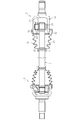
- FIG. 1 is a longitudinal sectional view showing an overall configuration of a tripod type constant velocity universal joint in an embodiment of the present invention.
- FIG. 2 is a view taken in the direction of arrow X in FIG. 1. It is sectional drawing which shows the state which the internal component of FIG. 1 interfered with the retaining plate.
- FIG. 4B is a cross-sectional view taken along the line PP in FIG. 4A. It is a front view which shows the example which changed the number of protrusions in the retaining plate of FIG. 4A.
- FIG. 8A It is a front view which shows the other example of a retaining plate. It is sectional drawing which follows the QQ line of FIG. 8A. It is a front view which shows the state which mounted
- FIG. 8A It is a front view which shows the state which mounted
- a single roller type tripod type constant velocity universal joint is illustrated.
- the present invention can also be applied to a double roller type tripod type constant velocity universal joint capable of reducing vibration during operation.
- the present invention can also be applied to other sliding type constant velocity universal joints such as a ball type double offset type constant velocity universal joint and a cross groove type constant velocity universal joint. is there.
- a drive shaft that transmits power from an automobile engine to a wheel needs to cope with an angular displacement and an axial displacement caused by a change in relative positional relationship between the wheel and a differential integrated with the engine / transmission. Therefore, as shown in FIG. 14, the drive shaft is connected to the engine side (the Rzeppa type constant velocity universal joint 1 which is one of the fixed type constant velocity universal joints that allows only angular displacement on the wheel side (outboard side).
- the tripod type constant velocity universal joint 2 which is one of the sliding constant velocity universal joints that allows both axial displacement and angular displacement, is mounted on the inboard side), and both constant velocity universal joints 1 and 2 are attached.
- a structure connected by a shaft 3 is provided.
- FIG. 1 and 2 show the overall configuration of the tripod type constant velocity universal joint 2 assembled to the drive shaft of FIG. 1 is a longitudinal sectional view with respect to the axis of the joint, and FIG. 2 is a view taken in the direction of arrow X in FIG. 1 (in FIG. 2, the boot is omitted and only one roller is shown in cross section).
- the tripod type constant velocity universal joint 2 (hereinafter simply referred to as a constant velocity universal joint) of this embodiment includes an outer joint member 11, a tripod member 12 which is an inner joint member, and three rollers 13 which are torque transmission members.
- the shaft 3 extending from the tripod member 12 and projecting from the opening 14 of the outer joint member 11 is coupled.
- the outer joint member 11 has a cup shape having an opening 14 at one end, and a shaft portion 15 is integrally formed at the bottom.
- three linear track grooves 16 extending in the axial direction are formed at three equal intervals in the circumferential direction of the cylindrical inner peripheral surface 17.
- Each track groove 16 has a pair of roller guide surfaces 18 opposed to each other on both inner walls thereof.
- the roller guide surface 18 has an arc-shaped cross section and extends linearly in the axial direction of the outer joint member 11.
- an internal component 19 composed of a tripod member 12 and a roller 13 is accommodated so as to be slidable in the axial direction.
- the tripod member 12 has three leg shafts 21 integrally formed radially at equal intervals in the circumferential direction (120 ° intervals) on the outer peripheral surface of a cylindrical boss 20.
- the leg shaft 21 has a distal end extending in the radial direction to the vicinity of the bottom of the track groove 16, and an outer peripheral surface thereof is generally a cylindrical surface.
- a shaft end portion 23 of the shaft 3 is coupled to the shaft hole 22 of the boss 20 by spline fitting, and is prevented from coming off from the tripod member 12 by a retaining ring 24.
- the roller 13 is rotatably disposed via a needle roller 25 between the roller guide surface 18 of the outer joint member 11 and the outer peripheral surface of the leg shaft 21.
- the outer peripheral surface of the roller 13 has an arcuate vertical cross section, and may contact the roller guide surface 18 at two locations by angular contact or contact at one location by circular contact.
- the inner peripheral surface of the roller 13 is formed in a cylindrical shape.
- a plurality of needle rollers 25 are arranged in a so-called single row full roller state without a cage.
- the outer peripheral surface of the leg shaft 21 constitutes the inner rolling surface of the needle roller 25, and the inner peripheral surface of the roller 13 constitutes the outer rolling surface of the needle roller 25.
- the needle roller 25 is in contact with the inner washer 26 fitted on the base of the leg shaft 21 on the inner side in the radial direction, and is in contact with the outer washer 27 fitted on the tip of the leg shaft 21 on the outer side in the radial direction. .
- the outer washer 27 is prevented from coming off by fitting a retaining ring 29 into an annular groove 28 formed at the tip of the leg shaft 21.
- the leg shaft 21 of the tripod member 12 and the roller guide surface 18 of the outer joint member 11 are engaged with each other in the biaxial rotation direction via the roller 13 to rotate from the driving side to the driven side. Torque is transmitted at a constant speed. Further, the roller 13 rolls on the roller guide surface 18 while rotating with respect to the leg shaft 21, thereby allowing relative axial displacement and angular displacement between the outer joint member 11 and the tripod member 12.
- a lubricant is sealed in the inner space of the outer joint member 11, so that the shaft 3 slides inside the joint during an operation of rotating while taking an operating angle with respect to the outer joint member 11. Lubricity is ensured at a part, that is, a sliding part constituted by the outer joint member 11, the tripod member 12 and the roller 13.
- the constant velocity universal joint 2 has an outer joint between the outer joint member 11 and the shaft 3 in order to prevent leakage of a lubricant such as grease enclosed in the joint and to prevent foreign matter from entering from the outside of the joint.
- a structure in which a rubber or resin boot 30 for sealing the opening 14 of the member 11 is mounted is provided.
- the boot 30 has a large-diameter end portion 32 fastened and fixed to the outer peripheral surface of the outer joint member 11 by a boot band 31 and a small-diameter end portion 34 fastened and fixed to the outer peripheral surface of the shaft 3 by a boot band 33 (see FIG. 14). (Refer to FIG. 14) and a large-diameter end portion 32 and a small-diameter end portion 34 are connected to each other, and a telescopic bellows portion 35 having a diameter reduced from the large-diameter end portion 32 toward the small-diameter end portion 34 is formed.
- a retaining plate 37 that regulates the amount of axial displacement of the internal component 19 is welded to the opening end surface 36 of the outer joint member 11. It uses a retaining structure that is joined together.
- the retaining plate 37 has a flat plate shape formed by pressing from a steel plate, and has a shape substantially coincident with the open end surface 36 of the outer joint member 11.
- the retaining plate 37 has a shape in which only a portion 38 (see FIG. 2) corresponding to the roller guide surface 18 on the opening end surface 36 of the outer joint member 11 protrudes inward from the end shape of the roller guide surface 18. .
- the portion 38 protruding from the roller guide surface 18 of the retaining plate 37 can interfere with the roller 13 at the time of sliding over.
- the retaining plate 37 may have any shape and size as long as it has a function of interfering with the roller 13.
- a welding projection 39 is provided on the surface of the outer joint member 11 that faces the opening end surface 36.
- the protrusions 39 can be simultaneously formed by press working when the retaining plate 37 is manufactured. Further, the protrusion 39 is disposed in the vicinity of a portion where the roller 13 of the internal component 19 interferes with the axial displacement of the internal component 19, that is, a portion 38 protruding from the roller guide surface 18.
- FIG. 4A shows the retaining plate 37 viewed from the side on which the projection 39 is formed
- FIG. 2 shows the retaining plate 37 viewed from the side opposite to the side on which the projection 39 is formed.
- the recessed part 40 (refer FIG. 4B) formed with formation of the permite
- FIG. 4A a case where protrusions 39 are provided at a total of six locations, two locations 38 that protrude from a pair of opposed roller guide surfaces 18 is illustrated.
- FIG. 5 you may make it provide the protrusion 39 in a total of three places one part of the part 38 which protruded from any one roller guide surface 18 among a pair of roller guide surfaces 18. As shown in FIG. .
- the protrusions 39 need to be provided at one or more of the portions 38 protruding from the roller guide surface 18 with respect to one roller 13, but the number and position satisfy the required pull-out resistance. What is necessary is just to set suitably.
- the retaining plate 37 having the above configuration is joined to the open end surface 36 of the outer joint member 11 by welding.
- the opening end surface 36 of the outer joint member 11 is a flat surface finished by turning.
- the protrusion 39 is brought into contact with the opening end surface 36 after positioning the retaining plate 37 with respect to the flat opening end surface 36 of the outer joint member 11. In this state, the protrusion 39 of the retaining plate 37 and the opening end surface 36 of the outer joint member 11 are joined by electric resistance welding (projection welding).
- Projection welding is a type of electrical resistance welding in which a large current is passed through a small point contact portion between the protrusion 39 and the flat opening end face 36, and the protrusion 39 and the opening end face 36 are partially melted by heat generated by the conduction resistance. By doing so, both are joined.
- This projection welding does not require a special material or welding environment, and is effective in joining the retaining plate 37 and the outer joint member 11.
- the projection 39 of the retaining plate 37 and the opening end surface 36 of the outer joint member 11 are joined by electric resistance welding, so that welding can be performed in a short time. And the retaining plate 37 can be firmly fixed to the outer joint member 11.
- joining of the retaining plate 37 and the outer joint member 11 may be welded for each protrusion 39, a plurality of protrusions 39 may be welded together.
- the protrusion 39 to be joined to the outer joint member 11 is close to a portion 38 protruding from the roller guide surface 18 of the retaining plate 37, that is, a portion where the internal component 19 interferes due to the axial displacement of the internal component 19. It is arranged. Thereby, the fixing of the retaining plate 37 to the outer joint member 11 is further ensured, and it is possible to reliably improve the slip-off resistance against the slide-over of the internal component 19.
- the retaining plate 37 has a simple structure in the form of a flat plate formed by pressing from a steel plate such as SPC. Accordingly, the retaining plate 37 can be easily manufactured, so that the cost can be reduced and the retaining plate 37 can be easily fixed to the outer joint member 11 by electric resistance welding. In addition, the outer joint member 11 can also be reduced in cost because only the flat opening end surface 36 is used without requiring partial processing.
- the retaining plate 37 described in the above embodiment has an annular shape as shown in FIGS. 4A and 5. Therefore, in order to attach the retaining plate 37 to the outer joint member 11, it is necessary to pass the retaining plate 37 through the shaft 3 in advance before the inner part 19 composed of the roller 13 and the tripod member 12 is assembled to the shaft 3. There is.
- a retaining plate 37 having a shape with a cutout at the top, or a retaining plate 37 having a shape with a cutout at the bottom as shown in FIG. In this way, if the retaining plate 37 has a shape with a part cut away, the retaining plate 37 can be attached to the outer joint member 11 even after the internal component 19 is assembled to the shaft 3. It is.
- the retaining plate 37 described in the above embodiment has a portion 38 that protrudes from the roller guide surface 18, the internal component 19 assembled to the shaft 3 is assembled into the outer joint member 11. It is necessary to join the retaining plate 37 to the opening end surface 36 of the outer joint member 11 by welding.
- the retaining plate 37 having the following structure, the retaining plate 37 is attached to the outer joint member 11 before the internal component 19 assembled to the shaft 3 is assembled into the outer joint member 11. It becomes possible to join to the opening end surface 36 by welding.
- the retaining plate 37 shown in FIGS. 8A and 8B has a bent portion 41 in which a portion that interferes with the internal component 19 is bent outward in the axial direction, and the internal component 19 is assembled when the internal component 19 is assembled into the outer joint member 11. It has a structure that does not interfere with.
- FIGS. 8A to 13 the same parts as those in FIGS. 1 to 7 are denoted by the same reference numerals, and the duplicate description is omitted.
- a bent portion 41 that is bent at a portion that interferes with the internal component 19 is a roller. It does not protrude from the guide surface 18. That is, the interval W1 between the opposite bent portions 41 is set to be larger than the maximum diameter D of the roller 13 (W1> D).
- the bent portion 41 formed at a site that interferes with the inner part 19 is bent back by plastic deformation.
- the bent portion 41 bent back by this plastic deformation becomes a portion 38 that is formed into a flat plate shape and protrudes from the roller guide surface 18 as shown in FIGS. 11 and 12. That is, the interval W2 between the portions 38 protruding from the roller guide surface 18 is smaller than the maximum diameter D of the roller 13 (W2 ⁇ D).
- the retaining plate 37 has a portion 38 protruding from the roller guide surface 18 and the internal part 19. By interfering with each other, a retaining function for preventing the internal component 19 from sliding over is exhibited.
- the retaining plate 37 ′ of the embodiment shown in FIG. 13 has a structure in which the retaining plate 37 shown in FIG. 9 is divided into three parts.
- the retaining plate 37 ′ has a shape that leaves a minimum part necessary for the function except for a portion corresponding to the track groove 16 in the annular retaining plate 37 (see FIG. 9).
Abstract
一端に開口部(14)を有するカップ状の外側継手部材(11)と、その外側継手部材(11)との間でローラ(13)を介して角度変位を許容しながらトルクを伝達するトリポード部材(12)とを備え、ローラ(13)およびトリポード部材(12)からなる内部部品(19)が外側継手部材(11)に軸方向摺動自在に収容された摺動式等速自在継手であって、外側継手部材(11)の開口端面(36)に、内部部品(19)の軸方向変位量を規制する抜け止めプレート(37)を電気抵抗溶接により接合する。
Description
本発明は、自動車や各種産業機械などの動力伝達系において使用され、特に、自動車用のドライブシャフトやプロペラシャフトに組み込まれる摺動式等速自在継手に関する。
自動車のエンジンから車輪に回転力を等速で伝達するドライブシャフトやプロペラシャフトに組み込まれる等速自在継手には、固定式等速自在継手と摺動式等速自在継手の二種がある。これら両者の等速自在継手は、駆動側と従動側の二軸を連結してその二軸が作動角をとっても等速で回転トルクを伝達し得る構造を備えている。
ドライブシャフトは、エンジン・トランスミッションと一体化されたデファレンシャルと車輪との相対的位置関係の変化による角度変位と軸方向変位に対応する必要がある。そのため、ドライブシャフトは、一般的に、エンジン側(インボード側)に軸方向変位および角度変位の両方を許容する摺動式等速自在継手を、車輪側(アウトボード側)に角度変位のみを許容する固定式等速自在継手をそれぞれ装備し、両者の等速自在継手をシャフトで連結した構造を具備する。
ドライブシャフトに組み付けられる摺動式等速自在継手の一つに、トルク伝達部材としてローラを用いたトリポード型等速自在継手(TJ)がある。また、他の摺動式等速自在継手には、トルク伝達部材としてボールを用いたダブルオフセット型等速自在継手(DOJ)やクロスグルーブ型等速自在継手(LJ)がある。
例えば、トリポード型等速自在継手は、一端に開口部を有するカップ状の外側継手部材と、その外側継手部材との間でローラを介して角度変位を許容しながらトルクを伝達する内側継手部材であるトリポード部材とを備え、ローラおよびトリポード部材からなる内部部品が外側継手部材に軸方向摺動自在に収容された構造を具備する。
このトリポード型等速自在継手では、継手内部に封入されたグリース等の潤滑剤の漏洩を防ぐと共に継手外部からの異物侵入を防止するため、外側継手部材の開口部と、トリポード部材から軸方向に延びるシャフトとの間に、樹脂製あるいはゴム製のブーツを装着した構造が一般的である。このブーツの端部は、外側継手部材およびシャフトにブーツバンドにより締め付け固定される。
ここで、ドライブシャフトを車体に組み付けるに際しては、以上の構成からなるトリポード型等速自在継手をエンジン側(インボード側)に組み付けた後、固定式等速自在継手を車輪側(アウトボード側)に組み付けるのが一般的である。その車輪側では、固定式等速自在継手に車輪用軸受を組み付け、ナックルにより車体の懸架装置に組み付ける。
ドライブシャフトのトリポード型等速自在継手を車体のエンジン側に組み付けた時点では、固定式等速自在継手が車輪側の車輪用軸受に組み付けられていない。そのため、トリポード型等速自在継手には、固定式等速自在継手およびシャフトからなるドライブシャフトの自重が大きな荷重となってスライドアウト方向へかかる場合がある。
このような状態になると、トリポード型等速自在継手の内部部品が外側継手部材の開口部から飛び出すスライドオーバーが生じることがある。このようなスライドオーバー時には、内部部品のローラが傾いた状態になったりすることで内部部品を外側継手部材に挿入し直すことが困難である。
そこで、従来のトリポード型等速自在継手では、内部部品のスライドオーバーを防止するため、外側継手部材に収容された内部部品の軸方向変位量を規制する種々の抜け止め機構が提案されている(例えば、特許文献1参照)。
前述の特許文献1で開示された従来の等速自在継手では、ローラおよびトリポード部材からなる内部部品の軸方向変位量を規制するストッパ部材を外側継手部材の開口端面に装着し、その外側継手部材の開口端面とブーツ端部の内側面とで挟み込むことにより取り付けた抜け止め機構を採用している。
この抜け止め機構では、ドライブシャフトを車体に組み付けるに際して、内部部品に大きな荷重がスライドアウト方向へかかった場合、内部部品のローラがストッパ部材と干渉することにより、外側継手部材に対する内部部品のスライドオーバーを防止するようにしている。
しかしながら、ドライブシャフトの車体への組み付け時には、前述したように、トリポード型等速自在継手に、固定式等速自在継手およびシャフトからなるドライブシャフトの自重が大きな荷重となってスライドアウト方向へかかる場合がある。
そのため、ストッパ部材を外側継手部材の開口端面とブーツ端部の内側面とで挟み込んだ取り付け構造、つまり、ブーツの端部を外側継手部材の外周面にブーツバンドで締め付け固定した構造では、ストッパ部材の抜け耐力がブーツの外側継手部材への締結力に等しく、ストッパ部材の十分な抜け耐力を確保することが困難である。
そこで、本発明は前述の問題点に鑑みて提案されたもので、その目的とするところは、内部部品のスライドオーバーを確実に防止するため、十分な抜け耐力を持ち得る抜け止め機構を具備した摺動式等速自在継手を提供することにある。
本発明に係る摺動式等速自在継手は、一端に開口部を有するカップ状の外側継手部材と、その外側継手部材との間でトルク伝達部材を介して角度変位を許容しながらトルクを伝達する内側継手部材とを備え、トルク伝達部材および内側継手部材を含む内部部品が外側継手部材に軸方向摺動自在に収容された構造を具備する。
前述の目的を達成するための技術的手段として、本発明は、外側継手部材の開口端面に、内部部品の軸方向変位量を規制する抜け止めプレートを溶接により接合したことを特徴とする。
本発明では、内部部品の軸方向変位量を規制する抜け止めプレートを外側継手部材の開口端面に溶接で接合したことにより、抜け止めプレートを外側継手部材に強固に固定することができる。その結果、内部部品が外側継手部材の開口部から飛び出すスライドオーバーに対して十分な抜け耐力を確保することができ、内部部品の抜け止め性能を向上させることができる。
本発明における抜け止めプレートは、外側継手部材の開口端面と対向する面に突起を設け、突起と外側継手部材の開口端面とを電気抵抗溶接により接合した構造が望ましい。このような構造を採用すれば、抜け止めプレートを外側継手部材により一層強固に固定することができ、内部部品のスライドオーバーに対する抜け耐力をより一層向上させることができる。
本発明における抜け止めプレートは、外側継手部材と接合される部位が、内部部品の軸方向変位により内部部品が干渉する部位に近接配置されている構造が望ましい。このような構造を採用すれば、外側継手部材に対する抜け止めプレートの固定がより一層確実となり、内部部品のスライドオーバーに対する抜け耐力を確実に向上させることができる。
本発明における抜け止めプレートは、外側継手部材の開口端面との接合後の塑性変形により、内部部品と干渉する部位が形成されている構造が望ましい。このような構造を採用すれば、内部部品を外側継手部材に組み込む前に、抜け止めプレートを外側継手部材の開口端面に溶接により接合しておくことが可能となる。
本発明における抜け止めプレートは、鋼板からプレス加工で成形された平板状をなす構造が望ましい。このような構造を採用すれば、抜け止めプレートを容易に製作することができ、その抜け止めプレートを外側継手部材に溶接で固定することが容易となる。
本発明によれば、内部部品の軸方向変位量を規制する抜け止めプレートを外側継手部材の開口端面に溶接で接合したことにより、抜け止めプレートを外側継手部材に強固に固定することができる。その結果、内部部品が外側継手部材の開口部から飛び出すスライドオーバーに対して十分な抜け耐力を確保することができ、内部部品の抜け止め性能を向上させた信頼性の高い安価な摺動式等速自在継手を実現することができる。
本発明に係る摺動式等速自在継手の実施形態を図面に基づいて以下に詳述する。
以下の実施形態では、シングルローラタイプのトリポード型等速自在継手を例示する。本発明は、シングルローラタイプ以外に、作動時の低振動化を可能としたダブルローラタイプのトリポード型等速自在継手にも適用可能である。また、本発明は、トリポード型等速自在継手以外に、ボールタイプのダブルオフセット型等速自在継手やクロスグルーブ型等速自在継手のような他の摺動式等速自在継手にも適用可能である。
自動車のエンジンから車輪に動力を伝達するドライブシャフトは、エンジン・トランスミッションと一体化されたデファレンシャルと車輪との相対的位置関係の変化による角度変位と軸方向変位に対応する必要がある。そのため、ドライブシャフトは、図14に示すように、車輪側(アウトボード側)に角度変位のみを許容する固定式等速自在継手の一つであるツェッパ型等速自在継手1を、エンジン側(インボード側)に軸方向変位および角度変位の両方を許容する摺動式等速自在継手の一つであるトリポード型等速自在継手2をそれぞれ装着し、両者の等速自在継手1,2をシャフト3で連結した構造を具備する。
図1および図2は、図14のドライブシャフトに組み付けられたトリポード型等速自在継手2の全体構成を示す。図1は、継手の軸線に対する縦断面図、図2は、図1のX矢視図である(図2では、ブーツを省略して一つのローラのみを断面で示す)。
この実施形態のトリポード型等速自在継手2(以下、単に等速自在継手と称す)は、外側継手部材11と、内側継手部材であるトリポード部材12と、トルク伝達部材である3個のローラ13とを備え、トリポード部材12から延びて外側継手部材11の開口部14から突出するシャフト3が結合されている。
外側継手部材11は、一端に開口部14を有するカップ状をなし、底部に軸部15が一体的に形成されている。外側継手部材11は、軸方向に延びる3本の直線状トラック溝16が円筒状内周面17の円周方向3箇所に等間隔で形成されている。各トラック溝16は、その内側両壁に互いに対向する一対のローラ案内面18を有する。ローラ案内面18は円弧状断面を有し、外側継手部材11の軸線方向に直線状に延びる。外側継手部材11の内部には、トリポード部材12とローラ13からなる内部部品19が軸方向摺動自在に収容されている。
トリポード部材12は、円筒状をなすボス20の外周面に3本の脚軸21が円周方向等間隔(120°間隔)で放射状に一体形成されている。脚軸21は、先端がトラック溝16の底部付近まで半径方向に延在し、外周面は一般的に円筒面とされている。ボス20の軸孔22にシャフト3の軸端部23がスプライン嵌合により結合され、止め輪24によりトリポード部材12に対して抜け止めされている。
外側継手部材11のローラ案内面18と脚軸21の外周面との間に針状ころ25を介してローラ13が回転自在に配設される。ローラ13の外周面は縦断面円弧状とされ、ローラ案内面18とアンギュラ接触により二箇所で接触する場合と、サーキュラ接触により一箇所で接触する場合がある。ローラ13の内周面は円筒状に形成されている。ローラ13と脚軸21との間に、複数の針状ころ25が、保持器のない、いわゆる単列総ころ状態で配設されている。脚軸21の外周面は針状ころ25の内側転動面を構成し、ローラ13の内周面は針状ころ25の外側転動面を構成している。
針状ころ25は、脚軸21の付け根部に外嵌されたインナワッシャ26と半径方向内側で接すると共に、脚軸21の先端部に外嵌されたアウタワッシャ27と半径方向外側で接している。アウタワッシャ27は、脚軸21の先端部に形成された環状溝28に止め輪29を嵌合させることにより抜け止めされている。
等速自在継手2では、トリポード部材12の脚軸21と外側継手部材11のローラ案内面18とがローラ13を介して二軸の回転方向に係合することにより、駆動側から従動側へ回転トルクが等速で伝達される。また、ローラ13が脚軸21に対して回転しながらローラ案内面18上を転動することにより、外側継手部材11とトリポード部材12との間の相対的な軸方向変位や角度変位が許容される。
この等速自在継手2では、外側継手部材11の内部空間に潤滑剤を封入することにより、外側継手部材11に対してシャフト3が作動角をとりながら回転する動作時において、継手内部の摺動部位、つまり、外側継手部材11、トリポード部材12およびローラ13で構成される摺動部位での潤滑性を確保するようにしている。
一方、等速自在継手2は、継手内部に封入されたグリース等の潤滑剤の漏洩を防ぐと共に継手外部からの異物侵入を防止するため、外側継手部材11とシャフト3との間に、外側継手部材11の開口部14を密封するゴム製または樹脂製のブーツ30を装着した構造を具備する。
ブーツ30は、外側継手部材11の外周面にブーツバンド31により締め付け固定された大径端部32と、シャフト3の外周面にブーツバンド33(図14参照)により締め付け固定された小径端部34(図14参照)と、大径端部32と小径端部34とを繋ぎ、大径端部32から小径端部34へ向けて縮径した伸縮自在な蛇腹部35とで構成されている。
以上の構成からなる等速自在継手2が組み付けられたドライブシャフトを車体に組み付けるに際して、ツェッパ型等速自在継手1(図14参照)およびシャフト3からなるドライブシャフトの自重が大きな荷重となってスライドアウト方向へかかる場合がある。その場合、内部部品19が外側継手部材11の開口部14から飛び出すスライドオーバーを防止する必要がある。
そこで、この実施形態の等速自在継手2は、図1および図2に示すように、外側継手部材11の開口端面36に、内部部品19の軸方向変位量を規制する抜け止めプレート37を溶接により接合した抜け止め構造を採用している。
抜け止めプレート37は、図4Aおよび図4Bに示すように、鋼板からプレス加工で成形した平板状をなし、外側継手部材11の開口端面36と略一致した形状を有する。抜け止めプレート37は、外側継手部材11の開口端面36においてローラ案内面18と対応する部位38(図2参照)のみ、ローラ案内面18の端部形状よりも内側に食み出した形状を有する。
以上のような形状とすることにより、抜け止めプレート37のローラ案内面18から食み出した部位38で、スライドオーバー時にローラ13と干渉可能としている。なお、抜け止めプレート37は、ローラ13と干渉する機能を有するのであれば、その形状および大きさは任意である。
抜け止めプレート37では、外側継手部材11の開口端面36と対向する面に溶接用の突起39を設けている。突起39は、抜け止めプレート37の製作時のプレス加工により同時に成形することが可能である。また、突起39は、内部部品19の軸方向変位により内部部品19のローラ13が干渉する部位、つまり、ローラ案内面18から食み出した部位38に近接配置されている。
なお、図4Aでは、突起39を形成した側から見た抜け止めプレート37を示すのに対して、図2では、突起39を形成した側の反対側から見た抜け止めプレート37を示すため、プレス加工による突起39の形成に伴って形成される凹部40(図4B参照)を示している。
この実施形態では、図4Aに示すように、対向する一対のローラ案内面18から食み出した部位38の2箇所ずつ計6箇所に突起39を設けた場合を例示する。なお、図5に示すように、一対のローラ案内面18のうち、いずれか一方のローラ案内面18から食み出した部位38の1箇所ずつ計3箇所に突起39を設けるようにしてもよい。
この突起39は、1個のローラ13に対して、ローラ案内面18から食み出した部位38の1箇所以上に設ける必要があるが、その個数および位置は、必要とされる抜け耐力を満足するように適宜設定すればよい。
以上の構成からなる抜け止めプレート37を外側継手部材11の開口端面36に溶接により接合する。一般的に、外側継手部材11の開口端面36は、旋削加工により仕上げられた平坦面となっている。この外側継手部材11の平坦な開口端面36に対して、抜け止めプレート37を位置決めした上で突起39を開口端面36に当接させる。この状態で、抜け止めプレート37の突起39と外側継手部材11の開口端面36とを電気抵抗溶接(プロジェクション溶接)により接合する。
プロジェクション溶接は、電気抵抗溶接の一種で、突起39と平坦な開口端面36との小さな点接触部に大電流を流し、その導通抵抗による発熱でもって突起39と開口端面36とが部分的に溶融することにより両者を接合するものである。このプロジェクション溶接では、特別な材料や溶接環境が不要であり、抜け止めプレート37と外側継手部材11とを接合する上で有効である。
以上のようにして、外側継手部材11の開口端面36に抜け止めプレート37を電気抵抗溶接(プロジェクション溶接)で接合したことにより、図3に示すように、内部部品19の軸方向変位時、その内部部品19のローラ13が抜け止めプレート37のローラ案内面18から食み出した部位38で干渉することにより内部部品19の軸方向変位量を規制する。これにより、内部部品19が外側継手部材11の開口部14から飛び出すスライドオーバーを防止する。
特に、トリポード型等速自在継手2が組み付けられたドライブシャフトを車体に組み付けるに際して、ツェッパ型等速自在継手1(図14参照)およびシャフト3からなるドライブシャフトの自重が大きな荷重となってトリポード型等速自在継手2のスライドアウト方向にかかった場合であっても、内部部品19のローラ13が抜け止めプレート37と干渉することで、その内部部品19のスライドオーバーを確実に防止することができる。その結果、ドライブシャフトの組み付け性が向上する。
以上のように、抜け止めプレート37を外側継手部材11に装着するに際して、抜け止めプレート37の突起39と外側継手部材11の開口端面36とを電気抵抗溶接で接合したことにより、短時間の溶接で接合することができ、抜け止めプレート37を外側継手部材11に強固に固定することができる。なお、抜け止めプレート37と外側継手部材11との接合は、突起39ごとに溶接してもよいが、複数の突起39をまとめて溶接してもよい。
その結果、内部部品19が外側継手部材11の開口部14から飛び出すスライドオーバーに対して十分な抜け耐力(例えば、ドライブシャフトの組み付け時で1kN程度)を確保することができ、内部部品19の抜け止め性能を向上させることができる。
また、外側継手部材11と接合される突起39を、抜け止めプレート37のローラ案内面18から食み出した部位38、つまり、内部部品19の軸方向変位により内部部品19が干渉する部位に近接配置している。これにより、外側継手部材11に対する抜け止めプレート37の固定がより一層確実となって、内部部品19のスライドオーバーに対する抜け耐力を確実に向上させることができる。
さらに、抜け止めプレート37は、SPC等の鋼板からプレス加工で成形された平板状をなす簡素な構造である。このことから、抜け止めプレート37を容易に製作することができるので、コスト低減が図れ、その抜け止めプレート37を外側継手部材11に電気抵抗溶接で固定することも容易となる。また、外側継手部材11についても、部分的な加工を必要とすることなく、平坦な開口端面36を使用するだけで済むので、この点でもコスト低減が図れる。
なお、以上の実施形態で説明した抜け止めプレート37は、図4Aおよび図5に示すように、環状をなす。そのため、この抜け止めプレート37を外側継手部材11に装着するには、ローラ13およびトリポード部材12からなる内部部品19をシャフト3に組み付ける前に、シャフト3に抜け止めプレート37を予め通しておく必要がある。
これに対して、図6に示すように、上部を切り欠いた形状の抜け止めプレート37や、図7に示すように、下部を切り欠いた形状の抜け止めプレート37であってもよい。このように、一部を切り欠いた形状の抜け止めプレート37であれば、内部部品19をシャフト3に組み付けた後であっても、抜け止めプレート37を外側継手部材11に装着することが可能である。
また、以上の実施形態で説明した抜け止めプレート37は、ローラ案内面18から食み出した部位38を有することから、シャフト3に組み付けられた内部部品19を外側継手部材11に組み込んだ後に、抜け止めプレート37を外側継手部材11の開口端面36に溶接により接合する必要がある。
これに対して、以下のような構造の抜け止めプレート37を採用することにより、シャフト3に組み付けられた内部部品19を外側継手部材11に組み込む前に、抜け止めプレート37を外側継手部材11の開口端面36に溶接により接合することが可能となる。
これにより、内部部品19を外側継手部材11に組み付けるドライブシャフトの組立工程とは別に、抜け止めプレート37を外側継手部材11に接合する溶接工程を設けることができ、既存の組立工程の変更を最小限にして、溶接工程の設備を簡素化することができる。
図8Aおよび図8Bに示す抜け止めプレート37は、内部部品19と干渉する部位を軸方向外側に曲げた曲成部41を有し、内部部品19を外側継手部材11に組み込む際に内部部品19と干渉しないようにした構造を具備する。なお、以下の図8A~図13において、図1~図7と同一部分には同一参照符号を付して重複説明は省略する。
この抜け止めプレート37を外側継手部材11の開口端面36に電気抵抗溶接により接合した状態では、図9および図10に示すように、内部部品19と干渉する部位を曲げた曲成部41がローラ案内面18から食み出していない。つまり、対向する曲成部41間の間隔W1がローラ13の最大直径Dよりも大きく設定されている(W1>D)。
この状態では、曲成部41が内部部品19と干渉しないように曲げられていることから、内部部品19が外側継手部材11の開口部14を通過することができ、シャフト3に組み付けられた内部部品19を外側継手部材11に組み込むことが可能である。
そして、シャフト3に組み付けられた内部部品19を外側継手部材11に組み込んだ後、内部部品19と干渉する部位に形成された曲成部41を塑性変形により曲げ戻す。この塑性変形により曲げ戻された曲成部41は、図11および図12に示すように、平板状に成形されてローラ案内面18から食み出した部位38となる。つまり、ローラ案内面18から食み出した部位38間の間隔W2がローラ13の最大直径Dよりも小さくなる(W2<D)。
このように、曲成部41を塑性変形により内部部品19と干渉する位置まで平板状に曲げ戻すことにより、抜け止めプレート37は、ローラ案内面18から食み出した部位38が内部部品19と干渉することで、その内部部品19のスライドオーバーを防止する抜け止め機能を発揮する。
また、図13に示す実施形態の抜け止めプレート37’は、図9に示す抜け止めプレート37を3分割した構造を具備する。この抜け止めプレート37’は、環状の抜け止めプレート37(図9参照)におけるトラック溝16と対応する部分を除いて、機能上必要な最小限部分を残した形状を有する。
このような3分割の抜け止めプレート37’を採用することにより、鋼板からプレス加工で成形する抜け止めプレート37’を製作するに際して、機能上必要な最小限部分で済むことから、歩留まりの向上が図れる。
本発明は前述した実施形態に何ら限定されるものではなく、本発明の要旨を逸脱しない範囲内において、さらに種々なる形態で実施し得ることは勿論のことであり、本発明の範囲は、請求の範囲によって示され、さらに請求の範囲に記載の均等の意味、および範囲内のすべての変更を含む。
Claims (5)
- 一端に開口部を有するカップ状の外側継手部材と、前記外側継手部材との間でトルク伝達部材を介して角度変位を許容しながらトルクを伝達する内側継手部材とを備え、前記トルク伝達部材および内側継手部材を含む内部部品が前記外側継手部材に軸方向摺動自在に収容された摺動式等速自在継手であって、
前記外側継手部材の開口端面に、前記内部部品の軸方向変位量を規制する抜け止めプレートを溶接により接合したことを特徴とする摺動式等速自在継手。 - 前記抜け止めプレートは、前記外側継手部材の開口端面と対向する面に突起を設け、前記突起と外側継手部材の開口端面とを電気抵抗溶接により接合した構造を具備する請求項1に記載の摺動式等速自在継手。
- 前記抜け止めプレートは、外側継手部材と接合される部位が、前記内部部品の軸方向変位により内部部品と干渉する部位に近接配置されている構造を具備する請求項1又は2に記載の摺動式等速自在継手。
- 前記抜け止めプレートは、外側継手部材の開口端面との接合後の塑性変形により、内部部品と干渉する部位が形成されている構造を具備する請求項1~3のいずれか一項に記載の摺動式等速自在継手。
- 前記抜け止めプレートは、鋼板からプレス加工で成形された平板状をなす請求項1~4のいずれか一項に記載の摺動式等速自在継手。
Applications Claiming Priority (4)
| Application Number | Priority Date | Filing Date | Title |
|---|---|---|---|
| JP2015220260 | 2015-11-10 | ||
| JP2015-220260 | 2015-11-10 | ||
| JP2016-179689 | 2016-09-14 | ||
| JP2016179689A JP2017089882A (ja) | 2015-11-10 | 2016-09-14 | 摺動式等速自在継手 |
Publications (1)
| Publication Number | Publication Date |
|---|---|
| WO2017081982A1 true WO2017081982A1 (ja) | 2017-05-18 |
Family
ID=58695099
Family Applications (1)
| Application Number | Title | Priority Date | Filing Date |
|---|---|---|---|
| PCT/JP2016/080621 WO2017081982A1 (ja) | 2015-11-10 | 2016-10-14 | 摺動式等速自在継手 |
Country Status (1)
| Country | Link |
|---|---|
| WO (1) | WO2017081982A1 (ja) |
Citations (6)
| Publication number | Priority date | Publication date | Assignee | Title |
|---|---|---|---|---|
| JPS5675323U (ja) * | 1979-11-13 | 1981-06-19 | ||
| JPS62248578A (ja) * | 1986-04-21 | 1987-10-29 | Canon Inc | プロジエクシヨン溶接方法 |
| JPH04171318A (ja) * | 1990-10-31 | 1992-06-18 | Ntn Corp | トリポード型等速自在継手の抜け止め装置 |
| JP2007064397A (ja) * | 2005-08-31 | 2007-03-15 | Ntn Corp | 等速自在継手 |
| JP2013079681A (ja) * | 2011-10-04 | 2013-05-02 | Ntn Corp | トリポード型等速自在継手 |
| JP2013177923A (ja) * | 2012-02-28 | 2013-09-09 | Ntn Corp | トリポード型等速自在継手 |
-
2016
- 2016-10-14 WO PCT/JP2016/080621 patent/WO2017081982A1/ja active Application Filing
Patent Citations (6)
| Publication number | Priority date | Publication date | Assignee | Title |
|---|---|---|---|---|
| JPS5675323U (ja) * | 1979-11-13 | 1981-06-19 | ||
| JPS62248578A (ja) * | 1986-04-21 | 1987-10-29 | Canon Inc | プロジエクシヨン溶接方法 |
| JPH04171318A (ja) * | 1990-10-31 | 1992-06-18 | Ntn Corp | トリポード型等速自在継手の抜け止め装置 |
| JP2007064397A (ja) * | 2005-08-31 | 2007-03-15 | Ntn Corp | 等速自在継手 |
| JP2013079681A (ja) * | 2011-10-04 | 2013-05-02 | Ntn Corp | トリポード型等速自在継手 |
| JP2013177923A (ja) * | 2012-02-28 | 2013-09-09 | Ntn Corp | トリポード型等速自在継手 |
Similar Documents
| Publication | Publication Date | Title |
|---|---|---|
| JP2009085380A (ja) | 等速自在継手 | |
| JP2010270825A (ja) | 等速自在継手 | |
| JP2008082393A (ja) | 自動車用駆動軸 | |
| WO2017081982A1 (ja) | 摺動式等速自在継手 | |
| JP2017089882A (ja) | 摺動式等速自在継手 | |
| JP2012189190A (ja) | 摺動式等速自在継手 | |
| JP2013177923A (ja) | トリポード型等速自在継手 | |
| JP4579112B2 (ja) | 摺動型等速自在継手及びその製造方法 | |
| WO2007049512A1 (ja) | 複合型等速自在継手 | |
| JP2009197920A (ja) | トリポード型等速自在継手 | |
| JP2011080554A (ja) | 等速自在継手 | |
| JP2015113875A (ja) | 等速自在継手 | |
| JP2011226588A (ja) | 摺動式等速自在継手 | |
| JP2010025207A (ja) | 等速自在継手 | |
| JP6253933B2 (ja) | 等速自在継手 | |
| JP2018084306A (ja) | 等速自在継手のシール構造 | |
| JP2013155803A (ja) | 摺動式等速自在継手 | |
| JP2020041662A (ja) | 摺動式等速自在継手 | |
| WO2017082068A1 (ja) | 摺動式等速自在継手 | |
| JP2017137943A (ja) | 摺動式等速自在継手及びその製造方法 | |
| JP2009121667A (ja) | 摺動式等速自在継手 | |
| JP2018044607A (ja) | 摺動式等速自在継手 | |
| JP2018185008A (ja) | 摺動式等速自在継手 | |
| JP2019124319A (ja) | 等速自在継手 | |
| JP2013234733A (ja) | 等速自在継手 |
Legal Events
| Date | Code | Title | Description |
|---|---|---|---|
| 121 | Ep: the epo has been informed by wipo that ep was designated in this application |
Ref document number: 16863946 Country of ref document: EP Kind code of ref document: A1 |
|
| NENP | Non-entry into the national phase |
Ref country code: DE |
|
| 122 | Ep: pct application non-entry in european phase |
Ref document number: 16863946 Country of ref document: EP Kind code of ref document: A1 |