WO2017081958A1 - 温度センサおよび位置検出装置 - Google Patents
温度センサおよび位置検出装置 Download PDFInfo
- Publication number
- WO2017081958A1 WO2017081958A1 PCT/JP2016/079550 JP2016079550W WO2017081958A1 WO 2017081958 A1 WO2017081958 A1 WO 2017081958A1 JP 2016079550 W JP2016079550 W JP 2016079550W WO 2017081958 A1 WO2017081958 A1 WO 2017081958A1
- Authority
- WO
- WIPO (PCT)
- Prior art keywords
- temperature sensor
- sensor element
- heat insulating
- holding
- insulating material
- Prior art date
Links
Images


Classifications
-
- G—PHYSICS
- G01—MEASURING; TESTING
- G01K—MEASURING TEMPERATURE; MEASURING QUANTITY OF HEAT; THERMALLY-SENSITIVE ELEMENTS NOT OTHERWISE PROVIDED FOR
- G01K1/00—Details of thermometers not specially adapted for particular types of thermometer
- G01K1/08—Protective devices, e.g. casings
- G01K1/12—Protective devices, e.g. casings for preventing damage due to heat overloading
-
- G—PHYSICS
- G01—MEASURING; TESTING
- G01K—MEASURING TEMPERATURE; MEASURING QUANTITY OF HEAT; THERMALLY-SENSITIVE ELEMENTS NOT OTHERWISE PROVIDED FOR
- G01K7/00—Measuring temperature based on the use of electric or magnetic elements directly sensitive to heat ; Power supply therefor, e.g. using thermoelectric elements
- G01K7/16—Measuring temperature based on the use of electric or magnetic elements directly sensitive to heat ; Power supply therefor, e.g. using thermoelectric elements using resistive elements
- G01K7/22—Measuring temperature based on the use of electric or magnetic elements directly sensitive to heat ; Power supply therefor, e.g. using thermoelectric elements using resistive elements the element being a non-linear resistance, e.g. thermistor
-
- G—PHYSICS
- G01—MEASURING; TESTING
- G01D—MEASURING NOT SPECIALLY ADAPTED FOR A SPECIFIC VARIABLE; ARRANGEMENTS FOR MEASURING TWO OR MORE VARIABLES NOT COVERED IN A SINGLE OTHER SUBCLASS; TARIFF METERING APPARATUS; MEASURING OR TESTING NOT OTHERWISE PROVIDED FOR
- G01D5/00—Mechanical means for transferring the output of a sensing member; Means for converting the output of a sensing member to another variable where the form or nature of the sensing member does not constrain the means for converting; Transducers not specially adapted for a specific variable
- G01D5/12—Mechanical means for transferring the output of a sensing member; Means for converting the output of a sensing member to another variable where the form or nature of the sensing member does not constrain the means for converting; Transducers not specially adapted for a specific variable using electric or magnetic means
-
- G—PHYSICS
- G01—MEASURING; TESTING
- G01K—MEASURING TEMPERATURE; MEASURING QUANTITY OF HEAT; THERMALLY-SENSITIVE ELEMENTS NOT OTHERWISE PROVIDED FOR
- G01K1/00—Details of thermometers not specially adapted for particular types of thermometer
- G01K1/08—Protective devices, e.g. casings
-
- G—PHYSICS
- G01—MEASURING; TESTING
- G01K—MEASURING TEMPERATURE; MEASURING QUANTITY OF HEAT; THERMALLY-SENSITIVE ELEMENTS NOT OTHERWISE PROVIDED FOR
- G01K7/00—Measuring temperature based on the use of electric or magnetic elements directly sensitive to heat ; Power supply therefor, e.g. using thermoelectric elements
- G01K7/16—Measuring temperature based on the use of electric or magnetic elements directly sensitive to heat ; Power supply therefor, e.g. using thermoelectric elements using resistive elements
- G01K7/22—Measuring temperature based on the use of electric or magnetic elements directly sensitive to heat ; Power supply therefor, e.g. using thermoelectric elements using resistive elements the element being a non-linear resistance, e.g. thermistor
- G01K7/24—Measuring temperature based on the use of electric or magnetic elements directly sensitive to heat ; Power supply therefor, e.g. using thermoelectric elements using resistive elements the element being a non-linear resistance, e.g. thermistor in a specially-adapted circuit, e.g. bridge circuit
-
- F—MECHANICAL ENGINEERING; LIGHTING; HEATING; WEAPONS; BLASTING
- F02—COMBUSTION ENGINES; HOT-GAS OR COMBUSTION-PRODUCT ENGINE PLANTS
- F02D—CONTROLLING COMBUSTION ENGINES
- F02D2200/00—Input parameters for engine control
- F02D2200/02—Input parameters for engine control the parameters being related to the engine
- F02D2200/04—Engine intake system parameters
- F02D2200/0406—Intake manifold pressure
-
- F—MECHANICAL ENGINEERING; LIGHTING; HEATING; WEAPONS; BLASTING
- F02—COMBUSTION ENGINES; HOT-GAS OR COMBUSTION-PRODUCT ENGINE PLANTS
- F02D—CONTROLLING COMBUSTION ENGINES
- F02D2200/00—Input parameters for engine control
- F02D2200/02—Input parameters for engine control the parameters being related to the engine
- F02D2200/04—Engine intake system parameters
- F02D2200/0414—Air temperature
Definitions
- the present invention relates to a temperature sensor for measuring the temperature of a fluid such as air sucked into an engine, and a position detection device including the temperature sensor.
- the temperature sensor is configured by using a temperature sensor element coated with glass or the like, and has a structure in which the temperature sensor element is arranged at a distal end portion in a tube with a closed distal end for protection.
- the tip of the temperature sensor element is brought into direct contact with the tube so that heat transfer to the temperature sensor element is enhanced.
- a method of preventing the heat transmitted to the temperature sensor element from escaping such as by providing an air layer in the tube other than the tip, is considered. It is done.
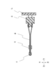
- FIG. 8 is a cross-sectional view of the temperature sensor 900 of Patent Document 1.
- the temperature sensor element 921 is disposed at the tip 912 in the tube 911.
- the rear end 945 of the insulator tube 941 is pushed to the front end side by utilizing deformation generated in the seal member 971, whereby the temperature sensor element 921 arranged on the front end side is moved to the front end 912 in the tube 911. Is pressed against.
- the present invention solves the above-described problems, and an object of the present invention is to provide a temperature sensor with a simpler configuration and good temperature detection performance, and a position detection device including the same.
- the temperature sensor of the present invention includes a main body part, a case having a tubular part formed outwardly projecting from the main body part and closed at the front end side, and a temperature sensor element disposed at the front end of the tubular part.
- a temperature sensor comprising: a wire connected to the temperature sensor element; and a holding part filled with a holding material that supports the wire on the side of the body part relative to the temperature sensor element inside the tubular part
- a heat insulating part including a heat insulating material that is less likely to transmit heat than the holding material is provided between the temperature sensor element and the holding part.
- the heat insulating part is provided between the temperature sensor element and the holding part, it is possible to make a structure in which heat does not easily escape from the temperature sensor element.
- a temperature sensor with good quality can be provided.
- the heat insulating portion is disposed in the vicinity of the temperature sensor element so that the heat insulating material is fixed to the wire.
- the temperature sensor element is pushed to the distal end side of the tubular portion through the heat insulating material when the holding material is filled.
- the temperature sensor element can be pressed against the distal end of the tubular portion without providing a biasing mechanism. Thereby, temperature detection performance improves.
- the temperature sensor of the present invention is characterized in that the heat insulating material is made of expanded polystyrene or phenol resin.
- This configuration can be easily arranged.
- the heat insulating portion includes a gas held between the heat insulating material and the temperature sensor element.
- the heat insulation is further improved by using a gas that is difficult to transmit heat as a part of the heat insulating portion.
- the position detection device of the present invention is a position detection device having position detection means for detecting the position of the detection object and temperature detection means for detecting the ambient temperature of the detection object.
- the temperature sensor is provided.
- control corresponding to the position of the detected object can be made more appropriate by detecting the ambient temperature of the detected object of the position detecting means.
- the heat insulating part is provided between the temperature sensor element and the holding part, it is possible to make a structure in which heat is difficult to escape from the temperature sensor element, so that the temperature detection can be performed with a simpler configuration.
- a temperature sensor with good performance can be provided.
- the position detection apparatus provided with the temperature sensor with good temperature detection performance can be provided.
- FIG.2 (a) is a top view
- FIG.2 (b) is a front view.
- FIG. 1 is a cross-sectional view showing a temperature sensor 10 according to a first embodiment of the present invention.
- 2 is an external view of the heat insulating material 31
- FIG. 2 (a) is a plan view
- FIG. 2 (b) is a front view.
- FIG. 3 is a cross-sectional view showing a state in which the holder 16, the heat insulating material 31, and the substrate 17 are fixed to the wire 14 connected to the temperature sensor element 11.
- FIG. 4 is a cross-sectional view of the case 20 before the lid 23 is attached.
- FIG. 5 is a cross-sectional view showing a state in which the temperature sensor element 11 is inserted into the tubular portion 22 of the case 20.
- FIG. 6 is a cross-sectional view showing a state in which the holding material 25 is filled.
- the temperature sensor 10 includes a case 20 in which a temperature sensor element 11 is accommodated, and is configured as shown in a cross-sectional view in FIG.
- the case 20 is formed from a synthetic resin material, and is formed into a box-shaped main body portion 21 having an opening surface, and a tubular shape that protrudes outward (Z2 direction in FIG. 1) from the main body portion 21 and is closed on the front end 22a side. And a lid portion 23 that closes the opening surface of the main body portion 21.
- the temperature sensor element 11 changes an electrical output according to the temperature, and can measure the ambient temperature based on the output value.
- the temperature sensor element 11 of the present embodiment uses a thermistor that is a resistor having a large change in electrical resistance with respect to a temperature change.
- the wire 14 connected to the temperature sensor element 11 is fixed to the holder 16 and is electrically connected to a wiring portion (not shown) of the substrate 17. Furthermore, a heat insulating material 31 is attached to the wire 14.
- the gap between the wire 14 and the tubular portion 22 and the gap between the holder 16 and the substrate 17 and the main body 21 are filled with a holding material 25 as shown in FIG.
- the holding material 25 of the present embodiment is a one-component epoxy resin, and the thermal conductivity at 20 ° C. is 0.3 [W / (m ⁇ K)].
- the holding material 25 is filled with a predetermined amount in a liquefied state and then cured by heat treatment.
- the temperature sensor 10 of this embodiment has the space
- the gas 32 in the present embodiment is air, and the thermal conductivity of air at 20 ° C. is 0.024 [W / (m ⁇ K)].
- the heat insulating material 31 a material having a physical property that is more difficult to transmit heat than the holding material 25 is preferably used.
- the heat insulating material 31 of the present embodiment is made of expanded polystyrene that is less likely to transfer heat than the holding material 25 and has no fluidity.
- the heat conductivity of the holding member 25 at 20 ° C. is 0.3 [W / (m ⁇ K)], whereas the heat conductivity of the heat insulating material 31 is 0.03 [W / (m ⁇ K). )].
- the heat insulating material 31 has a columnar outer shape, is provided with a cut from the side surface to the center, and a hole is formed in the center portion. Thereby, the heat insulating material 31 can be elastically deformed and can be attached so as to be fixed to the wire 14.
- the temperature sensor element 11 is pressed against the tip 22 a of the tubular portion 22 of the case 20. Thereby, heat transfer between the tip 22a and the temperature sensor element 11 is improved, and the ambient temperature around the tip 22a of the tubular portion 22 can be measured more accurately. Furthermore, as the heat insulating portion 30, a heat insulating material 31 that is less likely to transfer heat than the holding material 25 and a gas 32 held in the gap 22b between the heat insulating material 31 and the temperature sensor element 11 are on the main body 21 side. Since heat transmission is suppressed, the temperature sensor element 11 can respond quickly when the ambient temperature around the distal end 22a of the tubular portion 22 changes, and the heat response can be improved.
- the temperature sensor 10 of the present embodiment can be manufactured, for example, by the steps shown in FIGS.
- the wire 14 connected to the temperature sensor element 11 is fixed to the holder 16.
- the heat insulating material 31 is fixed to the wire 14 close to the temperature sensor element 11.
- the wire 14 is electrically connected to the substrate 17.
- incision of the heat insulating material 31 of this embodiment is devised so that the clearance gap between the heat insulating material 31 and the wire 14 may become small, you may fix using an adhesive etc., and in this case, it is a clearance gap. Even if it is large to some extent, it can be closed with an adhesive or the like.
- when closing a clearance gap with an adhesive etc. it is not limited to the material which is easy to be elastically deformed, The thing of a physical property to which heat is hard to transmit can be used. For example, a hard phenol resin can be used.
- a case 20 before the lid portion 23 is attached is prepared, and the temperature sensor element 11 is inserted so as to be disposed at the tip 22 a inside the tubular portion 22 as shown in FIG. 5.
- the outer shape of the heat insulating material 31 is set so as to have a slight gap with the inner wall of the tubular portion 22 and does not prevent the temperature sensor element 11 from being pushed to the tip 22a.
- the holder 16 abuts against the main body 21, but the wire 14 is prepared to be slightly long, and when the temperature sensor element 11 is pushed to the tip 22 a, the wire 14 is bent and is surely pushed. Yes.
- the holding material 25 is liquefied in the gap between the wire 14 and the tubular portion 22 and in the gap between the holder 16 and the substrate 17 and the main body portion 21 while holding the Z2 direction downward. Filled in state.
- the heat insulating material 31 is disposed in advance, a gap 22b that is not filled with the holding material 25 is formed between the heat insulating material 31 and the temperature sensor element 11 due to surface tension, and the remaining air is used as the gas 32. Retained.
- the heat insulating material 31 is arranged so as to be fixed to the wire rod 14, the temperature sensor element 11 is pushed to the distal end 22 a side of the tubular portion 22 through the heat insulating material 31 when the holding material 25 is filled.
- the temperature sensor element 11 can be pressed against the tip 22a of the tubular portion 22 without directing the urging mechanism.
- the holding member 25 may be applied to the end of the temperature sensor element 11 in advance so as to securely fix the temperature sensor element 11 to the tip 22a.
- the holding material 25 is cured by heat treatment, and the holding material 25 is supported by the holding material 25. Finally, the lid 23 is attached to the case 20.
- the heat insulating portion 30 is provided between the temperature sensor element 11 and the holding portion 22c, a structure in which heat does not easily escape from the temperature sensor element 11 can be obtained.
- the temperature sensor 10 of the present embodiment includes a case 20, a temperature sensor element 11, and a wire 14 connected to the temperature sensor element 11.
- the case 20 has a main body portion 21 and a tubular portion 22 that protrudes outward from the main body portion 21 and is formed in a tubular shape with the tip 22a side closed.
- the temperature sensor element 11 is disposed at the tip 22 a inside the tubular portion 22.
- maintenance material 25 which supports the wire 14 is provided in the main-body part 21 side rather than the temperature sensor element 11 inside the tubular part 22.
- a heat insulating portion 30 including a heat insulating material 31 that is less likely to transfer heat than the holding material 25 is provided between the temperature sensor element 11 and the holding portion 22c.
- the heat insulating portion 30 is provided between the temperature sensor element 11 and the holding portion 22c, it is possible to make a structure in which heat does not easily escape from the temperature sensor element 11, and thus a simpler configuration. Thus, it is possible to provide the temperature sensor 10 with good temperature detection performance.
- the heat insulating portion 30 is disposed in the vicinity of the temperature sensor element 11 so that the heat insulating material 31 is fixed to the wire 14.
- the temperature sensor element 11 is inserted into the distal end 22 a of the tubular portion 22 via the heat insulating material 31 when the holding material 25 is filled. Will be pushed to the side. For this reason, the temperature sensor element 11 can be pressed against the tip 22a of the tubular portion 22 without directing the biasing mechanism. Thereby, temperature detection performance improves.
- the heat insulating material 31 is made of expanded polystyrene or phenol resin.
- the thermal conductivity of the holding member 25 at 20 ° C. is 0.3 [W / (m ⁇ K)], whereas the thermal conductivity of the heat insulating material 31 is 0.03 [W in the case of expanded polystyrene. / (M ⁇ K)], and in the case of phenol resin, it is 0.13 to 0.25 [W / (m ⁇ K)].
- the heat is less likely to be transmitted than the holding material 25 and has no fluidity, so that it can be easily arranged.
- the heat insulating part 30 includes a gas 32 held between the heat insulating material 31 and the temperature sensor element 11. According to this configuration, heat insulation is further improved by using a gas that is difficult to transmit heat as a part of the heat insulating portion 30.
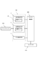
- FIG. 7 is a block diagram showing a position detection apparatus 100 according to the second embodiment of the present invention.
- the position detection device 100 of the present embodiment is an example of being attached to a throttle valve 220 that controls the output of the engine as shown in FIG.
- the position detection device 100 is not limited to this embodiment, and can be used for various purposes.
- a position detection device 100 shown in FIG. 7 detects position detection means 2 for detecting the position of the detection object, temperature detection means 1 for detecting the ambient temperature of the detection object, and pressure of the gas (atmosphere) to be sucked. Pressure detecting means 3 for performing the operation. And the temperature detection means 1 is provided with the temperature sensor 10 of 1st Embodiment.
- the position detecting means 2 detects the position of the object to be detected that moves in conjunction with the rotating shaft that adjusts the opening of the throttle valve 220. More specifically, the movable contact that moves according to the position of the object to be detected slides the resistor to change the resistance value, or the magnetic force of the magnet that moves according to the position of the object to be detected. A magnetic sensor to detect is used. A method of detecting the rotation angle in conjunction with the rotation shaft of the throttle valve 220, a method of mechanically converting to linear movement and detecting the position, or the like can be used.
- the pressure detection means 3 can use a pressure sensor or the like.
- the case 20 of the first embodiment is used as a common case for the position detection means 2 and the pressure detection means 3, and the temperature detection means 1, the position detection means 2, and the pressure detection means 3 are integrated into one body. It can be. Thereby, it is possible to detect the ambient temperature of the object to be detected by the position detection means 2 in close proximity with a small apparatus. Thereby, control of the fuel ejection amount of the injector 210 corresponding to the position of the detected object can be made more appropriate. In this way, the exhaust gas from the engine can be made cleaner.
- the position detection apparatus 100 includes a position detection unit 2 that detects the position of the detected object, and a temperature detection unit 1 that detects the ambient temperature of the detected object.
- a sensor 10 is provided.
- control corresponding to the position of the detected object can be made more appropriate by detecting the ambient temperature of the detected object of the position detecting means 2.
- the temperature sensor 10 according to the first embodiment of the present invention and the position detection device 100 according to the second embodiment have been specifically described.
- the present invention is not limited to the above-described embodiment, and is summarized.
- Various modifications can be made without departing from the scope of the invention.
- the present invention can be modified as follows, and these also belong to the technical scope of the present invention.
- the temperature sensor element 11 is a thermistor, but a thermocouple may be used.
- the tubular portion 22 of the case 20 is integrally formed of a synthetic resin material.
- the tubular portion 22 of the case 20 may be formed of a composite material in which the tip 22a portion has a better thermal conductivity. . If it carries out like this, it can be set as a thing with better thermal responsiveness.
- the heat insulation part 30 was set as the structure containing the gas 32 hold
- Temperature detection means 1 Temperature detection means 2 Position detection means 3 Pressure detection means 10 Temperature sensor 11 Temperature sensor element 14 Wire material 16 Holder 17 Board
Landscapes
- Physics & Mathematics (AREA)
- General Physics & Mathematics (AREA)
- Nonlinear Science (AREA)
- Measuring Temperature Or Quantity Of Heat (AREA)
Abstract
【課題】より簡単な構成で、温度検知性能のよい温度センサ、および、これを備えた位置検出装置を提供する。 【解決手段】本体部21および本体部21から外方へ突出し先端22a側が閉鎖された管状に形成された管状部22を有するケース20と、管状部22の内部の先端22aに配置される温度センサ素子11と、温度センサ素子11に接続された線材14と、を備えた温度センサ10において、管状部22の内部の温度センサ素子11よりも本体部21側には線材14を支持する保持材25が充填された保持部22cを有し、温度センサ素子11と保持部22cとの間には保持材25よりも熱が伝わりにくい断熱材31を含む断熱部30が設けられている。
Description
本発明は、エンジンに吸入する空気などの流体の温度を測定するための温度センサ、および、これを備えた位置検出装置に関する。
近年、車両の各種制御に温度センサが使用されている。温度センサは、ガラスなどでコーティングされた温度センサ素子を用いて構成され、保護用の先端が閉じられたチューブ内の先端部分に温度センサ素子を配置した構造をなしている。温度センサ素子の先端をチューブに直接接触させることで、温度センサ素子への熱の伝達性を高めるよう構成されている。しかしながら、温度センサ素子は熱が逃げてしまうと検知精度が悪くなるので、先端部分以外のチューブ内に空気層を設けるなどして、温度センサ素子に伝わった熱が逃げるのを防止する方法が考えられる。
このように、空気層を備えた構造としては、特許文献1に記載の構造が開示されている。図8は、特許文献1の温度センサ900の断面図である。温度センサ素子921は、図8に示すように、チューブ911内の先端912に配置されている。この構造では、シール部材971に発生する変形を利用して、碍子管941の後端945を先端側に押しており、これにより、先端側に配置された温度センサ素子921をチューブ911内の先端912に押し付けている。
しかしながら、シール部材971によって碍子管941を先端側に付勢する構造が必要になるため、構造が複雑になってしまうという課題があった。このため、より簡単な構成で温度センサに伝わった熱を逃がさない構造が要望されていた。
本発明は、上述した課題を解決するもので、より簡単な構成で、温度検知性能のよい温度センサ、および、これを備えた位置検出装置を提供することを目的とする。
本発明の温度センサは、本体部および前記本体部から外方へ突出し先端側が閉鎖された管状に形成された管状部を有するケースと、前記管状部の内部の先端に配置される温度センサ素子と、前記温度センサ素子に接続された線材と、を備えた温度センサにおいて、前記管状部の内部の前記温度センサ素子よりも前記本体部側には前記線材を支持する保持材が充填された保持部を有し、前記温度センサ素子と前記保持部との間には前記保持材よりも熱が伝わりにくい断熱材を含む断熱部が設けられていることを特徴とする。
この構成によれば、温度センサ素子と保持部との間に断熱部が設けられていることによって、温度センサ素子から熱が逃げにくい構造とすることができるので、より簡単な構成で温度検知性能のよい温度センサを提供することができる。
また、本発明の温度センサにおいて、前記断熱部は前記温度センサ素子に近接して前記断熱材が前記線材に固定されるように配置されていることが好ましい。
この構成によれば、断熱材が線材に固定されるように配置されることで、保持材が充填されたときに断熱材を介して温度センサ素子が管状部の先端側へ押されるため、付勢機構を設けることなく温度センサ素子を管状部の先端に押し付けることができる。これにより、温度検知性能がよくなる。
また、本発明の温度センサは、前記断熱材が発泡ポリスチレンまたはフェノール樹脂からなることを特徴とする。
この構成によれば、簡単に配置することができる。
また、本発明の温度センサにおいて、前記断熱部は前記断熱材と前記温度センサ素子との間に保持された気体を含むことを特徴とする。
この構成によれば、熱が伝わりにくい気体を断熱部の一部として利用することによって、断熱性がさらによくなる。
また、本発明の位置検出装置は、被検知物の位置を検出する位置検出手段と、前記被検知物の周囲温度を検知する温度検知手段と、を有する位置検出装置において、前記温度検知手段が上記の温度センサを備えることを特徴とする。
この構成によれば、位置検出手段の被検知物の周囲温度を検知することによって、被検知物の位置に対応した制御を、より適切にすることができる。
本発明によれば、温度センサ素子と保持部との間に断熱部が設けられていることによって、温度センサ素子から熱が逃げにくい構造とすることができるので、より簡単な構成で、温度検知性能のよい温度センサを提供することができる。また、温度検知性能のよい温度センサを備えた位置検出装置を提供することができる。
以下、本発明の実施の形態について図面を用いて詳細に説明する。なお、分かりやすいように、図面は寸法を適宜変更している。
[第1実施形態]
図1は、本発明の第1実施形態の温度センサ10を示す断面図である。図2は、断熱材31の外観図であり、図2(a)は平面図であり、図2(b)は正面図である。図3は、温度センサ素子11に接続された線材14にホルダ16と断熱材31と基板17が固定された状態を示す断面図である。図4は、蓋部23を取り付ける前のケース20の断面図である。図5は、温度センサ素子11がケース20の管状部22の内部に挿入された状態を示す断面図である。図6は、保持材25が充填された状態を示す断面図である。
図1は、本発明の第1実施形態の温度センサ10を示す断面図である。図2は、断熱材31の外観図であり、図2(a)は平面図であり、図2(b)は正面図である。図3は、温度センサ素子11に接続された線材14にホルダ16と断熱材31と基板17が固定された状態を示す断面図である。図4は、蓋部23を取り付ける前のケース20の断面図である。図5は、温度センサ素子11がケース20の管状部22の内部に挿入された状態を示す断面図である。図6は、保持材25が充填された状態を示す断面図である。
本発明の第1実施形態の温度センサ10は、ケース20に温度センサ素子11が収容されたものであり、図1に示す断面図のように構成されている。
ケース20は、合成樹脂材から成形され、開口面を備えた箱型の本体部21と、本体部21から外方(図1のZ2方向)へ突出し、先端22a側が閉鎖された管状に形成された管状部22と、本体部21の開口面を塞ぐ蓋部23とを有している。
温度センサ素子11は、その温度に応じて電気的な出力を変化させるものであり、その出力値によって周囲温度を測定することができる。本実施形態の温度センサ素子11は、温度変化に対して電気抵抗の変化の大きい抵抗体であるサーミスタ(Thermistor)が用いられている。温度センサ素子11に接続された線材14は、ホルダ16に固定されるとともに、基板17の図示しない配線部に電気接続されている。さらに、線材14には断熱材31が取り付けられている。
線材14と管状部22との隙間、ならびに、ホルダ16および基板17と本体部21との隙間には、図1に示すように、保持材25が充填されている。本実施形態の保持材25は、1液性のエポキシ樹脂で、20℃における熱伝導率は0.3[W/(m・K)]である。保持材25は、所定の量が液化した状態で充填されてから、熱処理によって硬化されている。なお、本実施形態の温度センサ10は、断熱材31と温度センサ素子11との間に保持材25が充填されず、気体32が残存している空隙部22bを有している。なお、本実施形態の気体32は空気であり、空気の20℃における熱伝導率は0.024[W/(m・K)]である。
断熱材31は、保持材25よりも熱が伝わりにくい物性のものが好適に用いられる。本実施形態の断熱材31は、保持材25よりも熱が伝わりにくく、かつ、流動性が無い発泡ポリスチレンからなる。なお、20℃における保持部材25の熱伝導率は0.3[W/(m・K)]であるのに対して、断熱材31の熱伝導率は0.03[W/(m・K)]である。断熱材31は、図2に示すように、柱状の外形を有し、側面から中央に切り込みが設けられて、中心部分に孔が形成されている。これによって、断熱材31が、弾性変形可能であり、線材14に固定されるように取り付けることができる。
温度センサ素子11は、ケース20の管状部22の先端22aに押し付けられている。これにより、先端22aと温度センサ素子11との熱伝達が良くなり、より正確に管状部22の先端22aの周囲温度を測定することができる。さらに、断熱部30として、保持材25よりも熱が伝わりにくい断熱材31と、断熱材31と温度センサ素子11との間の空隙部22bに保持された気体32とが、本体部21側に熱が伝わるのを抑制するので、管状部22の先端22aの周囲温度が変化したときに、温度センサ素子11が素早く応答する、熱応答性のよいものとすることができる。
本実施形態の温度センサ10は、例えば、図3~図6に示す工程で製造することができる。
図3に示すように、温度センサ素子11に接続された線材14がホルダ16に固定されている。そして、温度センサ素子11に近接して断熱材31が線材14に固定される。さらに、基板17に線材14が電気接続される。なお、断熱材31と線材14との隙間が小さくなるように、本実施形態の断熱材31の切り込みが工夫されているが、接着材等を用いて固定してもよく、この場合には隙間がある程度大きくても接着材等で塞ぐことが可能である。また、接着材等で隙間を塞ぐ場合は、弾性変形しやすい材料に限定されず、熱が伝わりにくい物性のものを使用することができる。例えば、フェノール樹脂の硬いものを使用することもできる。
図4に示すように蓋部23を取り付ける前のケース20が用意され、図5に示すように、温度センサ素子11が管状部22の内部の先端22aに配置されるように挿入される。このとき、断熱材31の外形は管状部22の内壁と僅かに隙間を有するように設定されて、温度センサ素子11が先端22aまで押し込まれるのを妨げない。また、ホルダ16は本体部21に当接するが、線材14は僅かに長く用意されて、温度センサ素子11が先端22aまで押し込まれると線材14が撓むことによって確実に押し込まれた状態となっている。
次に、図6に示すように、Z2方向を下向きに保持し、線材14と管状部22との隙間、ならびに、ホルダ16および基板17と本体部21との隙間に、保持材25が液化した状態で充填される。このとき、あらかじめ断熱材31が配置されているので、表面張力によって断熱材31と温度センサ素子11との間には保持材25が充填されない空隙部22bが形成され、残存する大気が気体32として保持される。また、断熱材31が線材14に固定されるように配置されていることで、保持材25が充填されたときに断熱材31を介して温度センサ素子11が管状部22の先端22a側へ押されることになる。このため、付勢機構を向けることなく、温度センサ素子11を管状部22の先端22aに押し付けることができる。なお、先端22aに温度センサ素子11を確実に固定するように、あらかじめ保持材25を温度センサ素子11の端部に塗布しておいてもよい。
その後、熱処理によって保持材25が硬化され、線材14を保持材25が支持する状態となる。最後に、ケース20に蓋部23が取り付けられる。
温度センサ素子11と保持部22cとの間に断熱部30が設けられていることによって、温度センサ素子11から熱が逃げにくい構造とすることができる。
以下、本実施形態としたことによる効果について説明する。
本実施形態の温度センサ10は、ケース20と、温度センサ素子11と、温度センサ素子11に接続された線材14とを備える。ケース20は、本体部21、および、本体部21から外方へ突出し、先端22a側が閉鎖された管状に形成された管状部22を有する。温度センサ素子11は、管状部22の内部の先端22aに配置される。そして、管状部22の内部の温度センサ素子11よりも本体部21側には線材14を支持する保持材25が充填された保持部22cを有している。さらに、温度センサ素子11と保持部22cとの間には保持材25よりも熱が伝わりにくい断熱材31を含む断熱部30が設けられている。
この構成によれば、温度センサ素子11と保持部22cとの間に断熱部30が設けられていることによって、温度センサ素子11から熱が逃げにくい構造とすることができるので、より簡単な構成で温度検知性能のよい温度センサ10を提供することができる。
また、本実施形態の温度センサ10において、断熱部30は温度センサ素子11に近接して断熱材31が線材14に固定されるように配置されていることが好ましい。
この構成によれば、断熱材31が線材14に固定されるように配置されることで、保持材25が充填されたときに断熱材31を介して温度センサ素子11が管状部22の先端22a側へ押されることになる。このため、付勢機構を向けることなく温度センサ素子11を管状部22の先端22aに押し付けることができる。これにより、温度検知性能がよくなる。
また、本実施形態の温度センサ10は、断熱材31が発泡ポリスチレンまたはフェノール樹脂からなる。なお、20℃における保持部材25の熱伝導率は0.3[W/(m・K)]であるのに対して、断熱材31の熱伝導率は発泡ポリスチレンの場合は0.03[W/(m・K)]であり、フェノール樹脂の場合は0.13~0.25[W/(m・K)]である。この構成によれば、保持材25よりも熱が伝わりにくく、かつ、流動性が無い断熱材であるので、簡単に配置することができる。
また、本実施形態の温度センサ10において、断熱部30は断熱材31と温度センサ素子11との間に保持された気体32を含む。この構成によれば、熱が伝わりにくい気体を断熱部30の一部として利用することによって、断熱性がさらによくなる。
[第2実施形態]
図7は、本発明の第2実施形態の位置検出装置100を示すブロック図である。
図7は、本発明の第2実施形態の位置検出装置100を示すブロック図である。
本実施形態の位置検出装置100は、図7に示すように、エンジンの出力を制御するスロットルバルブ220に取り付けられた事例である。なお、位置検出装置100は、この実施態様に限定されるものでなく、種々の用途で使用可能である。
図7に示す位置検出装置100は、被検知物の位置を検出する位置検出手段2と、被検知物の周囲温度を検知する温度検知手段1と、吸入される気体(大気)の圧力を検知する圧力検知手段3とを有している。そして、温度検知手段1が、第1実施形態の温度センサ10を備えている。
位置検出手段2は、スロットルバルブ220の開度を調整する回転軸に連動して移動する被検知物の位置を検出する。より具体的には、被検知物の位置に応じて移動する可動接点が抵抗体を摺動して抵抗値が変化する可変抵抗器や、被検知物の位置に応じて移動する磁石の磁力を検知する磁気センサが使用される。スロットルバルブ220の回転軸に連動して回転角度を検知する方式や機械的に直線移動に変換して位置検出する方式等を用いることができる。
圧力検知手段3は、圧力センサ等を使用することができる。
これらの出力値がエンジン制御部200に伝達され、インジェクタ210の燃料噴出量を最適化する。
位置検出装置100は、第1実施形態のケース20を、位置検出手段2および圧力検知手段3の共用のケースとして、温度検知手段1、位置検出手段2および圧力検知手段3が一体に組み込まれるものとすることができる。これにより、小型の装置で、かつ、位置検出手段2の被検知物の周囲温度を近接して検知することが可能である。これにより、被検知物の位置に対応したインジェクタ210の燃料噴出量の制御を、より適切にすることができる。こうすれば、エンジンからの排気ガスをよりきれいなものとすることができる。
以下、本実施形態としたことによる効果について説明する。
本実施形態の位置検出装置100は、被検知物の位置を検出する位置検出手段2と、被検知物の周囲温度を検知する温度検知手段1とを有し、温度検知手段1が上記の温度センサ10を備えることを特徴とする。
この構成によれば、位置検出手段2の被検知物の周囲温度を検知することによって、被検知物の位置に対応した制御を、より適切にすることができる。
以上のように、本発明の第1実施形態の温度センサ10および第2実施形態の位置検出装置100を具体的に説明したが、本発明は上記の実施形態に限定されるものではなく、要旨を逸脱しない範囲で種々変更して実施することが可能である。例えば次のように変形して実施することができ、これらも本発明の技術的範囲に属する。
(1)本実施形態において、温度センサ素子11はサーミスタが用いられているとしたが、熱電対を用いてもよい。
(2)本実施形態において、ケース20の管状部22は、合成樹脂材で一体形成されたものとしたが、先端22a部分をより熱伝導性のよい材料とする複合材料で形成してもよい。こうすれば、より熱応答性のよいものとすることができる。
(3)本実施形態において、断熱部30は断熱材31と温度センサ素子11との間に保持された気体32を含む構成としたが、断熱材31の性能が十分であれば、断熱材31と温度センサ素子11とが接するように配置してもよい。
1 温度検知手段
2 位置検出手段
3 圧力検知手段
10 温度センサ
11 温度センサ素子
14 線材
16 ホルダ
17 基板
20 ケース
21 本体部
22 管状部
22a 先端
22b 空隙部
22c 保持部
23 蓋部
25 保持材
30 断熱部
31 断熱材
32 気体
100 位置検出装置
200 エンジン制御部
210 インジェクタ
220 スロットルバルブ
2 位置検出手段
3 圧力検知手段
10 温度センサ
11 温度センサ素子
14 線材
16 ホルダ
17 基板
20 ケース
21 本体部
22 管状部
22a 先端
22b 空隙部
22c 保持部
23 蓋部
25 保持材
30 断熱部
31 断熱材
32 気体
100 位置検出装置
200 エンジン制御部
210 インジェクタ
220 スロットルバルブ
Claims (5)
- 本体部および前記本体部から外方へ突出し先端側が閉鎖された管状に形成された管状部を有するケースと、前記管状部の内部の先端に配置される温度センサ素子と、前記温度センサ素子に接続された線材と、を備えた温度センサにおいて、
前記管状部の内部の前記温度センサ素子よりも前記本体部側には前記線材を支持する保持材が充填された保持部を有し、
前記温度センサ素子と前記保持部との間には前記保持材よりも熱が伝わりにくい断熱材を含む断熱部が設けられていることを特徴とする温度センサ。 - 前記断熱部は前記温度センサ素子に近接して前記断熱材が前記線材に固定されるように配置されていることを特徴とする請求項1に記載の温度センサ。
- 前記断熱材は発泡ポリスチレンまたはフェノール樹脂からなることを特徴とする請求項1または請求項2に記載の温度センサ。
- 前記断熱部は前記断熱材と前記温度センサ素子との間に保持された気体を含むことを特徴とする請求項1ないし請求項3のいずれかに記載の温度センサ。
- 被検知物の位置を検出する位置検出手段と、前記被検知物の周囲温度を検知する温度検知手段と、を有する位置検出装置において、
前記温度検知手段が請求項1ないし請求項4のいずれかに記載の温度センサを備えることを特徴とする位置検出装置。
Priority Applications (5)
| Application Number | Priority Date | Filing Date | Title |
|---|---|---|---|
| KR1020187013020A KR102122140B1 (ko) | 2015-11-12 | 2016-10-04 | 온도 센서 및 위치 검출 장치 |
| JP2017550027A JP6702624B2 (ja) | 2015-11-12 | 2016-10-04 | 温度センサおよび位置検出装置 |
| EP16863922.7A EP3376190B1 (en) | 2015-11-12 | 2016-10-04 | Temperature sensor and position sensing device |
| CN201680062665.2A CN108351259B (zh) | 2015-11-12 | 2016-10-04 | 温度传感器以及位置检测装置 |
| US15/942,879 US20180224336A1 (en) | 2015-11-12 | 2018-04-02 | Temperature sensor and position detection device |
Applications Claiming Priority (2)
| Application Number | Priority Date | Filing Date | Title |
|---|---|---|---|
| JP2015-222110 | 2015-11-12 | ||
| JP2015222110 | 2015-11-12 |
Related Child Applications (1)
| Application Number | Title | Priority Date | Filing Date |
|---|---|---|---|
| US15/942,879 Continuation US20180224336A1 (en) | 2015-11-12 | 2018-04-02 | Temperature sensor and position detection device |
Publications (1)
| Publication Number | Publication Date |
|---|---|
| WO2017081958A1 true WO2017081958A1 (ja) | 2017-05-18 |
Family
ID=58695070
Family Applications (1)
| Application Number | Title | Priority Date | Filing Date |
|---|---|---|---|
| PCT/JP2016/079550 WO2017081958A1 (ja) | 2015-11-12 | 2016-10-04 | 温度センサおよび位置検出装置 |
Country Status (6)
| Country | Link |
|---|---|
| US (1) | US20180224336A1 (ja) |
| EP (1) | EP3376190B1 (ja) |
| JP (1) | JP6702624B2 (ja) |
| KR (1) | KR102122140B1 (ja) |
| CN (1) | CN108351259B (ja) |
| WO (1) | WO2017081958A1 (ja) |
Citations (4)
| Publication number | Priority date | Publication date | Assignee | Title |
|---|---|---|---|---|
| JPS49105178U (ja) * | 1972-12-07 | 1974-09-09 | ||
| JPS63168833U (ja) * | 1987-04-23 | 1988-11-02 | ||
| JP2008020395A (ja) * | 2006-07-14 | 2008-01-31 | Toyo Denso Co Ltd | エンジン用多機能検出装置 |
| JP2010151805A (ja) * | 2008-11-20 | 2010-07-08 | Tdk Corp | 温度センサ |
Family Cites Families (13)
| Publication number | Priority date | Publication date | Assignee | Title |
|---|---|---|---|---|
| JP2000088673A (ja) * | 1998-09-17 | 2000-03-31 | Denso Corp | 温度センサ |
| US6390670B1 (en) * | 1999-08-06 | 2002-05-21 | Pgi International Ltd. | Temperature sensing device for metering fluids |
| JP2002267547A (ja) * | 2001-03-14 | 2002-09-18 | Denso Corp | 温度センサ |
| JP2004317499A (ja) * | 2003-03-28 | 2004-11-11 | Ngk Spark Plug Co Ltd | 温度センサ |
| JP4422988B2 (ja) * | 2003-08-08 | 2010-03-03 | キヤノン株式会社 | 位置検出装置、光学装置、撮像システムおよびプログラム |
| EP1714122B1 (de) * | 2004-02-09 | 2013-11-13 | Temperaturmesstechnik Geraberg GmbH | Hochtemperatursensor |
| JP4620400B2 (ja) * | 2004-07-16 | 2011-01-26 | 日本特殊陶業株式会社 | 温度センサ、温度センサの製造方法 |
| JP4832044B2 (ja) * | 2005-09-28 | 2011-12-07 | 株式会社山武 | 温度検出体 |
| CN101398332B (zh) * | 2007-09-24 | 2010-09-01 | 北京亚都新风节能技术有限公司 | 用于监控外界温度的温度传感器 |
| JP5134701B2 (ja) * | 2010-07-20 | 2013-01-30 | 日本特殊陶業株式会社 | 温度センサ |
| CN204214555U (zh) * | 2014-09-30 | 2015-03-18 | 天津鑫德信科技有限公司 | 一种温度传感器 |
| JP2016130633A (ja) * | 2015-01-13 | 2016-07-21 | アズビル株式会社 | 温度センサ |
| CN204931646U (zh) * | 2015-05-19 | 2016-01-06 | 深圳市睿臻信息技术服务有限公司 | 适用于穿戴设备的包裹式温度传感器 |
-
2016
- 2016-10-04 EP EP16863922.7A patent/EP3376190B1/en active Active
- 2016-10-04 CN CN201680062665.2A patent/CN108351259B/zh active Active
- 2016-10-04 JP JP2017550027A patent/JP6702624B2/ja active Active
- 2016-10-04 KR KR1020187013020A patent/KR102122140B1/ko active IP Right Grant
- 2016-10-04 WO PCT/JP2016/079550 patent/WO2017081958A1/ja unknown
-
2018
- 2018-04-02 US US15/942,879 patent/US20180224336A1/en not_active Abandoned
Patent Citations (4)
| Publication number | Priority date | Publication date | Assignee | Title |
|---|---|---|---|---|
| JPS49105178U (ja) * | 1972-12-07 | 1974-09-09 | ||
| JPS63168833U (ja) * | 1987-04-23 | 1988-11-02 | ||
| JP2008020395A (ja) * | 2006-07-14 | 2008-01-31 | Toyo Denso Co Ltd | エンジン用多機能検出装置 |
| JP2010151805A (ja) * | 2008-11-20 | 2010-07-08 | Tdk Corp | 温度センサ |
Non-Patent Citations (1)
| Title |
|---|
| See also references of EP3376190A4 * |
Also Published As
| Publication number | Publication date |
|---|---|
| EP3376190A1 (en) | 2018-09-19 |
| EP3376190A4 (en) | 2019-08-14 |
| CN108351259A (zh) | 2018-07-31 |
| US20180224336A1 (en) | 2018-08-09 |
| KR20180066173A (ko) | 2018-06-18 |
| JP6702624B2 (ja) | 2020-06-03 |
| CN108351259B (zh) | 2021-06-01 |
| JPWO2017081958A1 (ja) | 2018-07-19 |
| KR102122140B1 (ko) | 2020-06-11 |
| EP3376190B1 (en) | 2021-06-09 |
Similar Documents
| Publication | Publication Date | Title |
|---|---|---|
| JP5395897B2 (ja) | 高振動対応抵抗温度センサ | |
| JP5741327B2 (ja) | 回転電機 | |
| JP2007127638A5 (ja) | ||
| JP5834167B1 (ja) | 温度センサ | |
| US20150292954A1 (en) | Temperature sensor | |
| CN105466626A (zh) | 薄膜压力传感器及其制造方法 | |
| JP5185429B2 (ja) | 内部に流体が流れる被計測物の曲面の表面温度計測用温度計の施工方法、その表面温度の計測方法、及びこれらの方法に使用する穴あけ治具 | |
| JP5959111B2 (ja) | 熱流センサ | |
| WO2017057668A1 (ja) | 流量センサ | |
| WO2017081958A1 (ja) | 温度センサおよび位置検出装置 | |
| JP2007198806A (ja) | 温度センサ | |
| JP6804439B2 (ja) | 迅速応答センサ筐体 | |
| CN203133107U (zh) | 一种集成温度检测的压电式加速度传感器 | |
| JP2015064223A (ja) | 環境試験装置 | |
| JP5812077B2 (ja) | 温度センサ | |
| KR102565161B1 (ko) | 습도 산출용 측정 센서 | |
| CN107870051B (zh) | 一种热感式压力传感器 | |
| US11156493B2 (en) | Filling level indicator | |
| US20210033473A1 (en) | Temperature Sensor | |
| JP5688678B2 (ja) | 温度測定装置 | |
| JP2017015504A (ja) | 温度センサ | |
| BR102022011578A2 (pt) | Dispositivo de sensor de temperatura com alojamento isolante | |
| JP2023128675A (ja) | 温度センサ | |
| JP2022003357A (ja) | シース型測温抵抗体の製造方法 | |
| TWM458548U (zh) | 線圈式磁吸感溫器 |
Legal Events
| Date | Code | Title | Description |
|---|---|---|---|
| 121 | Ep: the epo has been informed by wipo that ep was designated in this application |
Ref document number: 16863922 Country of ref document: EP Kind code of ref document: A1 |
|
| ENP | Entry into the national phase |
Ref document number: 2017550027 Country of ref document: JP Kind code of ref document: A |
|
| ENP | Entry into the national phase |
Ref document number: 20187013020 Country of ref document: KR Kind code of ref document: A |
|
| NENP | Non-entry into the national phase |
Ref country code: DE |