WO2017077855A1 - フィルター付きガスケット - Google Patents
フィルター付きガスケット Download PDFInfo
- Publication number
- WO2017077855A1 WO2017077855A1 PCT/JP2016/080823 JP2016080823W WO2017077855A1 WO 2017077855 A1 WO2017077855 A1 WO 2017077855A1 JP 2016080823 W JP2016080823 W JP 2016080823W WO 2017077855 A1 WO2017077855 A1 WO 2017077855A1
- Authority
- WO
- WIPO (PCT)
- Prior art keywords
- gasket
- filter
- outer peripheral
- gasket body
- filter member
- Prior art date
- Legal status (The legal status is an assumption and is not a legal conclusion. Google has not performed a legal analysis and makes no representation as to the accuracy of the status listed.)
- Ceased
Links
Images



Classifications
-
- B—PERFORMING OPERATIONS; TRANSPORTING
- B01—PHYSICAL OR CHEMICAL PROCESSES OR APPARATUS IN GENERAL
- B01D—SEPARATION
- B01D29/00—Filters with filtering elements stationary during filtration, e.g. pressure or suction filters, not covered by groups B01D24/00 - B01D27/00; Filtering elements therefor
- B01D29/01—Filters with filtering elements stationary during filtration, e.g. pressure or suction filters, not covered by groups B01D24/00 - B01D27/00; Filtering elements therefor with flat filtering elements
-
- B—PERFORMING OPERATIONS; TRANSPORTING
- B01—PHYSICAL OR CHEMICAL PROCESSES OR APPARATUS IN GENERAL
- B01D—SEPARATION
- B01D46/00—Filters or filtering processes specially modified for separating dispersed particles from gases or vapours
- B01D46/10—Particle separators, e.g. dust precipitators, using filter plates, sheets or pads having plane surfaces
-
- F—MECHANICAL ENGINEERING; LIGHTING; HEATING; WEAPONS; BLASTING
- F16—ENGINEERING ELEMENTS AND UNITS; GENERAL MEASURES FOR PRODUCING AND MAINTAINING EFFECTIVE FUNCTIONING OF MACHINES OR INSTALLATIONS; THERMAL INSULATION IN GENERAL
- F16J—PISTONS; CYLINDERS; SEALINGS
- F16J15/00—Sealings
- F16J15/02—Sealings between relatively-stationary surfaces
- F16J15/06—Sealings between relatively-stationary surfaces with solid packing compressed between sealing surfaces
- F16J15/10—Sealings between relatively-stationary surfaces with solid packing compressed between sealing surfaces with non-metallic packing
-
- F—MECHANICAL ENGINEERING; LIGHTING; HEATING; WEAPONS; BLASTING
- F16—ENGINEERING ELEMENTS AND UNITS; GENERAL MEASURES FOR PRODUCING AND MAINTAINING EFFECTIVE FUNCTIONING OF MACHINES OR INSTALLATIONS; THERMAL INSULATION IN GENERAL
- F16J—PISTONS; CYLINDERS; SEALINGS
- F16J15/00—Sealings
- F16J15/02—Sealings between relatively-stationary surfaces
- F16J15/06—Sealings between relatively-stationary surfaces with solid packing compressed between sealing surfaces
- F16J15/10—Sealings between relatively-stationary surfaces with solid packing compressed between sealing surfaces with non-metallic packing
- F16J15/12—Sealings between relatively-stationary surfaces with solid packing compressed between sealing surfaces with non-metallic packing with metal reinforcement or covering
Definitions
- the present invention relates to a gasket with a filter. Specifically, even if different pressures are applied on the upper and lower sides of the filter member due to a differential pressure, the seal state can be maintained and the seal can be prevented from being lost, and the gasket body can be bitten.
- the present invention relates to a gasket with a filter in which no occurrence occurs.
- Patent Documents 1 and 2 Conventionally, as a gasket with a filter, an annular gasket body made of a rubber-like elastic material is integrally formed on the peripheral edge of a filter member (Patent Documents 1 and 2).
- This gasket with a filter is mounted in a housing that forms a flow path of a fluid such as gas or oil, for example, in automobiles, industrial machinery and the like, and is sandwiched from above and below to filter the fluid by a filter member. And has a role of sealing the flow path by elastic deformation of the gasket body.
- a fluid such as gas or oil
- the conventional general gasket is designed on the assumption that the fluid pressure acts uniformly.
- the filter gasket creates a differential pressure before and after it due to the presence of the filter member. Different pressures may be applied. At this time, there is no problem when the differential pressure is small.
- the differential pressure is large, in the conventional gasket with a filter, it is difficult to maintain the posture of the seal by the gasket body, and the sealing function may be deteriorated.
- FIGS. 8 (a) to 8 (c) are explanatory views showing a state in which a conventional gasket with a filter is mounted with a minimum tightening allowance.
- 100 is a gasket with a filter
- 101 is a filter member
- 102 is a gasket body provided on the peripheral edge of the filter member 101
- 200 is a housing
- 300 is a cylinder block.
- the gasket main body 102 is formed of an annular body having a substantially rectangular cross section.
- the gasket body 102 is slightly elastically deformed as shown by the solid line in FIG. Seal between the block 300.
- the lower fluid pressure is P11
- the upper fluid pressure is not shown, but is smaller than P11.
- different pressures are applied to the gasket main body 102 with the filter member 101 as a boundary, and the lower fluid pressure applies a larger pressure than the upper fluid pressure.
- the gasket body 102 cannot maintain an appropriate posture between the housing 200 and the cylinder block 300, and the sealing state between the gasket body 102 and the housing 200 becomes unstable. There is a risk of missing the seal.
- FIG. 9 is an explanatory view showing a state in which a conventional gasket with a filter is mounted with a maximum tightening allowance.
- the gasket body 102 is greatly compressed, and therefore the position of the gasket body 102 varies even if different pressures are applied on the upper and lower sides with the filter member 101 as a boundary. There is no fear of causing seal omission.
- the gasket body 102 that is greatly compressed is deformed so as to enter the corner portion of the inner peripheral surface of the housing 200. As shown in the drawing, at a portion where the abutting surface between the housing 200 and the cylinder block 300 is disposed at the corner portion, the gasket body 102 is bitten by this corner portion (A portion shown in FIG. 9). There is a case.
- the present invention is a filter that can maintain a sealed state and prevent omission of a seal and prevent the gasket body from being bitten even when different pressures are applied on the upper and lower sides of the filter member due to a differential pressure. It is to provide a gasket with a seal.
- a filter member having a net part, and an annular gasket body made of a rubber-like elastic material provided on the peripheral edge of the filter member, On the upper and lower surfaces of the gasket main body, annular seal lip portions that fall toward the inner peripheral side when sandwiched from above and below are respectively formed.
- a filter characterized in that an outer peripheral projection that comes into contact with an inner peripheral surface of the mounting portion with a predetermined allowance is formed on the outer peripheral surface of the gasket main body so as to protrude in the radial direction of the gasket main body.
- the gasket with a filter according to claim 1 or 2 wherein a distal end portion of the outer peripheral projection is formed to be smaller than an axial width of the gasket body. 4). 4. The gasket with a filter according to claim 1, 2 or 3, wherein the outer peripheral projection has a tapered surface inclined from the tip portion to the upper and lower surfaces of the gasket body.
- the seal can be maintained and the seal can be prevented from coming off, and the gasket body can be prevented from being bitten.
- An attached gasket can be provided.
- the top view which shows one Embodiment of the gasket with a filter which concerns on this invention Sectional view taken along line (ii)-(ii) in FIG. Partial sectional view showing a state where the gasket with filter shown in FIG. (A) is explanatory drawing of the state in which the pressure is equally acting on the gasket main body shown in FIG. 3, (b) is different pressure was applied to the gasket main body shown in FIG.
- State explanatory diagram Partial sectional view showing a state in which the gasket with filter shown in FIG. (A) is a fragmentary sectional view which shows other embodiment of the gasket with a filter concerning this invention
- (b) is a fragmentary sectional view which shows other embodiment of the gasket with a filter concerning this invention.
- the top view which showed the shape of the filter of the gasket with a filter concerning the present invention (A) is explanatory drawing which shows the state which mounted
- FIG. 1 is a plan view showing an embodiment of a gasket with a filter according to the present invention
- FIG. 2 is a sectional view taken along line (ii)-(ii) in FIG.
- the gasket with filter 1 includes a filter member 2 and an annular gasket body 3 made of a rubber-like elastic material provided on the peripheral edge 22 of the filter member 2.
- the filter member 2 shown in the present embodiment is formed of a metal such as stainless steel or a synthetic resin such as polyamide. Although the filter member 2 shown in this embodiment is formed in a disk shape, it is not limited at all.
- the filter member 2 has a net portion 21 on the center side, and integrally includes a peripheral edge portion 22 on the outer peripheral side of the net portion 21.
- the gasket body 3 is formed so as to wrap the peripheral portion 22 of the filter member 2 from the upper surface and the lower surface.
- the gasket body 3 is formed integrally with the peripheral edge of the filter member 2.
- the vertical direction is referred to as an axial direction as necessary.
- Examples of the rubber-like elastic material used for the gasket body 3 include ethylene propylene diene terpolymer (EPDM), fluorine rubber (FKM), hydrogenated nitrile rubber (HNBR), nitrile rubber (NBR), natural rubber ( NR), acrylate rubber (ACM) and the like can be appropriately selected and used.
- EPDM ethylene propylene diene terpolymer
- FKM fluorine rubber
- HNBR hydrogenated nitrile rubber
- NBR nitrile rubber
- NR natural rubber
- ACM acrylate rubber
- the gasket body 3 has an annular seal lip portion 31. And the seal lip part 31 is formed in the upper surface and lower surface at the inner peripheral end side of the gasket main body 3, respectively.
- the shape of the seal lip portion 31 is shown in FIG.
- each seal lip portion 31 shown in FIG. 2 is an inner peripheral surface 31a extending in a direction perpendicular to the filter member 2.
- the outer periphery of each seal lip portion 31 is an inclined surface 31 b that is inclined toward the outer periphery of the gasket body 3.
- the seal lip portion 31 has an inner peripheral surface 31 a extending in the vertical direction with respect to the filter member 2, while an outer peripheral inclined surface 31 b is inclined toward the outer periphery of the gasket body 3. ing. Therefore, the seal lip portion 31 is configured to be slightly inclined toward the inner peripheral side. Thereby, as will be described in detail later, when the gasket 1 with a filter is mounted in the mounting portion and is sandwiched from above and below by the two members, each of the seal lip portions 31 is pressed by the two members. 3 is configured to fall toward the inner peripheral side.
- the outer peripheral projection 32 protruding to the outer periphery is integrally formed on the outer peripheral surface of the gasket body 3 over the entire periphery.
- an outer peripheral projection 32 formed so as to protrude in a mountain shape is shown on the outer periphery of the gasket body 3.
- the outer peripheral protrusion 32 is a portion that contacts the inner peripheral surface of the mounting portion with a predetermined tightening margin when the filter-equipped gasket 1 is mounted in the mounting portion.
- the tip 32a of the chevron-shaped outer peripheral projection 32 is formed in a band shape having a width smaller than the axial width of the gasket body 3, so that the cross-sectional shape is axial in the direction shown in FIG. It is a flat surface.
- tip part 32a to the upper and lower surfaces of the gasket main body 3 is the taper surface 32b, and it has the shape which cut off the up-and-down outer peripheral edge part of the gasket main body 3 diagonally.
- FIG. 3 is a partial cross-sectional view showing a state in which the filter-equipped gasket 1 is mounted with the minimum tightening allowance
- FIG. 4A is a state in which pressure is equally applied to the gasket body 3 shown in FIG.
- Explanatory drawing (b) is explanatory drawing of the state which applied the pressure which was different by the upper and lower sides to the gasket main body 3 shown in FIG.
- the mounting portion 6 of the gasket 1 with a filter is constituted by two members, a housing 4 and a cylinder block 5 that is abutted against the housing 4.
- the mounting portion 6 is formed with a predetermined depth only on the housing 4 side.
- the depth of the mounting portion 6 of the housing 4 is the axial direction in the initial state (no pressure state) of the entire gasket body 3 including the upper and lower seal lip portions 31 indicated by broken lines in FIG.
- the thickness is slightly smaller than the thickness along the line. Therefore, when the filter-equipped gasket 1 is sandwiched between the housing 4 and the cylinder block 5 from above and below, each seal lip portion 31 is pressed against the housing 4 and the cylinder block 5 as shown by a solid line in FIG. Thus, it is elastically deformed so as to fall slightly to the inner peripheral side, and the space between the housing 4 and the cylinder block 5 is sealed by the repulsive force.
- each seal lip portion 31 is disposed on the inner peripheral side of the gasket body 3, when sandwiched from above and below, the seal lip portion 31 can be smoothly tilted to the inner periphery side with little interference with other portions of the gasket body 3. It is like that.
- the filter-equipped gasket 1 has an outer peripheral projection 32 that is in contact with the inner peripheral surface 6 a of the mounting portion 6 with a predetermined tightening margin. Since the gasket body 3 is supported in the mounting portion 6 by the three points of the upper and lower seal lip portions 31 and the outer peripheral projection portion 32, it is sealed against the inner peripheral surface 6a of the mounting portion 6 by the portion 32. The posture can be stabilized.
- the above-described pressure P1 acts so as to deform the lower seal lip portion 31 more toward the outer peripheral side than the upper seal lip portion 31.
- the lower seal lip portion 31 is in pressure contact with the housing 4 even when the filter member 2 moves upward due to the pressure P1 and the seal pressure decreases. As a result, the sealing state by the lower seal lip portion 31 can be maintained.
- the gasket with filter 1 when different pressures are applied on the upper and lower sides with the filter member 2 as a boundary, the gasket with filter 1 is displaced from the broken line position in FIG. 4B to the solid line position. Specifically, the lower seal lip portion 31 is deformed toward the outer peripheral side, and the upper seal lip portion 31 is deformed toward the inner peripheral side. That is, the gasket main body 3 acts to rotate clockwise in FIG. 4B around the fixing portion with the filter member 2.
- the lower pressure P1 becomes excessive, it is assumed that the filter-equipped gasket 1 is further displaced upward, and the lower seal lip portion 31 receives the pressure P1 and falls to the outer peripheral side.
- the force to rotate the gasket body 3 increases the contact force of the outer peripheral projection 32 to the inner peripheral surface 6a of the mounting portion 6 and functions to prevent the rotation of the gasket body 3.
- the posture of the gasket body 3 is maintained in an appropriate state to maintain a stable seal state and prevent the occurrence of seal omission.
- the gasket main body 3 is brought into contact with the inner peripheral surface of the mounting portion 6 by the distal end portion 32a. Is exerted on the surface to effectively prevent the rotation of the gasket body 3. Thereby, the attitude
- FIG. 5 is a partial cross-sectional view showing a state in which the filter-equipped gasket 1 is mounted with the maximum tightening allowance.
- the depth of the mounting portion 6 of the housing 4 is based on the thickness along the axial direction of the initial state (no pressure state) of the entire gasket body 3 including the upper and lower seal lip portions 31 indicated by broken lines in FIG. Is also quite small. Therefore, when the filter-equipped gasket 1 is sandwiched between the housing 4 and the cylinder block 5 from above and below, each seal lip portion 31 is pressed against the housing 4 and the cylinder block 5 as indicated by a solid line in FIG. Thus, it is elastically deformed so as to fall greatly to the inner peripheral side, and the space between the housing 4 and the cylinder block 5 is sealed by the repulsive force. In this state, even if different pressures are applied to the gasket body 3 on the upper and lower sides with the filter member 2 as a boundary, the gasket with filter 1 is hardly displaced up and down. It is in a compressed state.
- the seal lip portion 31 is tilted toward the inner peripheral side, and further has an outer peripheral protrusion 32, whereby a gap S is formed between the upper and lower outer peripheral ends of the gasket body 3 and the inner surface of the mounting portion 6. .
- the gasket main body 3 is greatly compressed, the gasket main body 3 is bitten into the abutting surface (A portion in FIG. 5) between the housing 4 and the cylinder block 5 located at the corner of the mounting portion 6. There is no end.
- the outer peripheral projection 32 shown in the present embodiment has a tapered surface 32b extending vertically from the tip 32a, a large gap S is secured. For this reason, when the gasket main body 3 receives an excessive pressure of fluid from the inner peripheral side, even if it is pressed to the outer peripheral side as shown by a broken line in FIG.
- the gasket 1 with a filter according to the present invention even if different pressures are applied on the upper and lower sides with the filter member 2 as a boundary due to the differential pressure, the seal state can be maintained and seal omission can be prevented.
- the gasket body 3 is not bitten.
- FIG. 6 is a partial cross-sectional view showing another embodiment of the gasket with filter according to the present invention.
- the gasket 1 with a filter shown in FIG. 6A is obtained by shifting the seal lip portion 31 of the gasket main body 3 to the outer peripheral side from the above-described aspect and disposing it at the substantially central portion in the radial direction of the gasket main body 3. . Even when shifted to the outer peripheral side in this way, the tip of each seal lip portion 31 is formed so as to be gently inclined toward the inner peripheral side, so that it is described above when sandwiched from above and below by two members. Similar to the embodiment, it can be deformed so as to fall down toward the inner peripheral side, and a reliable sealing function can be exhibited.
- the outer peripheral protrusion 32 of the gasket body 3 has a tapered surface 32b from the top end 32a to the top and bottom, even when the gasket body 3 is compressed with the maximum tightening allowance, the biting is the same as above. There is no risk of it occurring.
- the outer peripheral protrusion 32 protruding from the outer peripheral surface of the gasket main body 3 is not in the above-described mountain shape, but in a strip shape smaller than the axial width of the gasket main body 3. It is formed so as to protrude. That is, the distal end portion 32a of the outer circumferential protrusion 32 has a cross-sectional shape that is a flat surface as shown in the figure, but has a shape that protrudes from the outer circumferential surface of the gasket body 3 while maintaining the width of the distal end portion 32a. .
- the gasket body 3 has a function of properly maintaining the posture of the gasket body 3, and even when different pressures are applied on the upper and lower sides from the inner peripheral side of the gasket body 3 with the filter member 2 as a boundary,
- the outer peripheral projection 32 effectively prevents the rotation of the gasket body 3 and can maintain the proper posture of the gasket body 3.
- the lattice shape of the filter in the above-mentioned gasket 1 with a filter shown in FIG. 1 is the spider web of the same figure (a) (b) or the same figure (c) as shown in FIG.
- Other shapes can be used in addition to the shape.
- Gasket with filter 2 Filter member 21: Net part 22: Peripheral part 3: Gasket body 31: Seal lip part 31a: Inner peripheral surface 31b: Inclined surface 32: Peripheral protrusion 32a: Tip 32b: Tapered surface 4: Housing 5: Cylinder block 6: Mounting part 6a: Inner peripheral surface
Landscapes
- Engineering & Computer Science (AREA)
- General Engineering & Computer Science (AREA)
- Mechanical Engineering (AREA)
- Chemical & Material Sciences (AREA)
- Chemical Kinetics & Catalysis (AREA)
- Gasket Seals (AREA)
- Filtering Of Dispersed Particles In Gases (AREA)
- Filtration Of Liquid (AREA)
Abstract
本発明は、差圧によってフィルター部材2を境にして上下側で異なった圧力が加わっても、シール状態を維持してシール抜けを防止できると共に、ガスケット本体の噛み込みが生じることのないフィルター付きガスケットを提供することを課題とし、当該課題は、網部を有するフィルター部材2と、フィルター部材2の周縁部に設けられたゴム状弾性材からなる環状のガスケット本体3とからなり、ガスケット本体3の上下面に、上下から挟着された際に内周側に向けて倒れる環状のシールリップ部31がそれぞれ形成されていると共に、ガスケット本体3の外周面に、装着部6の内周面と所定の締め代を有して接する外周突起部32が、ガスケット本体3の径方向に突出するように形成されていることで解決される。
Description
本発明は、フィルター付きガスケットに関し、詳しくは、差圧によってフィルター部材を境にして上下側で異なった圧力が加わっても、シール状態を維持してシール抜けを防止できると共に、ガスケット本体の噛み込みが生じることのないようにしたフィルター付きガスケットに関する。
従来、フィルター付きガスケットとして、フィルター部材の周縁部に、ゴム状弾性材からなる環状のガスケット本体を一体形成したものが知られている(特許文献1、2)。
このフィルター付きガスケットは、例えば、自動車、産業機械器具等において、ガスやオイル等の流体の流路を形成するハウジング内に装着され、上下から挟着されることにより、フィルター部材によって流体をろ過し、かつガスケット本体の弾性変形によって流路をシールする役割を有する。
従来の一般的なガスケットは、流体の圧力が均一に作用することを想定して設計されている。しかし、フィルター付きガスケットは、使用される流体が脈動するものや高粘度のものである場合、フィルター部材があることによって、その前後で差圧が生じ、ガスケット本体に、フィルター部材を境にして大小異なる圧力が加わる場合がある。このとき、差圧が小さい場合には問題はないが、差圧が大きくなると、従来のフィルター付きガスケットでは、ガスケット本体によるシールの姿勢保持が難しくなり、シール機能が低下する場合があった。
これを図8、図9を用いて説明する。
図8(a)~(c)は、従来のフィルター付きガスケットを最小締め代で装着した状態を示す説明図である。図中、100はフィルター付きガスケット、101はフィルター部材、102はフィルター部材101の周縁部に設けられたガスケット本体、200はハウジング、300はシリンダブロックである。
このフィルター付きガスケット100において、ガスケット本体102は、断面が略矩形状となる環状体によって形成されている。フィルター付きガスケット100をハウジング200とシリンダブロック300との間で挟着すると、図8(a)中の実線で示すように、ガスケット本体102が僅かに弾性変形し、その反発力によってハウジング200とシリンダブロック300との間をシールする。
この状態で、図8(b)に示すように、フィルター部材101を境にしてガスケット本体102の内周面に均等に流体の圧力P00が加わると、ガスケット本体102の上下端部がそれぞれ圧力に応じて外周側に倒れ込むように変形する。この外周側への倒れ込みは、ガスケット本体102の上下端部でそれぞれほぼ均等となるため、ガスケット本体102は、ハウジング200とシリンダブロック300との間で適正な姿勢を保持でき、シール状態を維持することができる。
図8(c)に示すように、フィルター部材101を境にして、下側の流体圧力がP11となり、上側の流体圧力は図示しないが、P11より小さい圧力になる。この場合、ガスケット本体102に対して、フィルター部材101を境にして異なった圧力が加わることになり、下側の流体圧力の方が上側の流体圧力に対して大きい圧力が加わるため、ガスケット本体102の下端部の方が上端部より外周側への倒れ込みが大きくなる。その結果、ガスケット本体102は、ハウジング200とシリンダブロック300との間で適正な姿勢を保持できなくなり、ガスケット本体102とハウジング200との間のシール状態が不安定となることにより、最悪の場合、シール抜けを生じさせるおそれがある。
一方、図9は、従来のフィルター付きガスケットを最大締め代で装着した状態を示す説明図である。
この場合、フィルター付きガスケット100をハウジング200とシリンダブロック300との間で挟着すると、図9中の実線で示すように、ガスケット本体102が大きく圧縮され、その反発力によってハウジング200とシリンダブロック300との間をシールする。
この最大締め代状態では、ガスケット本体102は大きく圧縮された状態であるため、フィルター部材101を境にして上下側で異なった圧力が加わっても、作用してもガスケット本体102が位置変動することはなく、シール抜けを生じさせるおそれはない。しかし、大きく圧縮されたガスケット本体102が、ハウジング200の内周面の隅角部まで入り込むように変形する。そして、図示するようにハウジング200とシリンダブロック300との突き合わせ面が隅角部に配置されるような部位では、この隅角部(図9中に示すA部)にガスケット本体102が噛み込まれる場合がある。変形したガスケット本体102の外周側の上下端は、隅角部に向けて角張った形状となることにより、隅角部Aの突き合わせ面間に侵入し易くなるためである。ガスケット本体102の噛み込みは、ガスケット本体102の損傷につながり、シール性能に影響を及ぼす場合がある。
そこで、本発明は、差圧によってフィルター部材を境にして上下側で異なった圧力が加わっても、シール状態を維持してシール抜けを防止できると共に、ガスケット本体の噛み込みが生じることのないフィルター付きガスケットを提供することにある。
また本発明の他の課題は、以下の記載によって明らかとなる。
上記課題は、以下の各発明によって解決される。
1.網部を有するフィルター部材と、前記フィルター部材の周縁部に設けられたゴム状弾性材からなる環状のガスケット本体とからなり、
前記ガスケット本体の上下面に、上下から挟着された際に内周側に向けて倒れる環状のシールリップ部がそれぞれ形成されていると共に、
前記ガスケット本体の外周面に、装着部の内周面と所定の締め代を有して接する外周突起部が、前記ガスケット本体の径方向に突出するように形成されていることを特徴とするフィルター付きガスケット。
2.前記シールリップ部は、前記ガスケット本体の内周端側の上下面にそれぞれ形成されていることを特徴とする前記1記載のフィルター付きガスケット。
3.前記外周突起部の先端部は、前記ガスケット本体の軸方向幅よりも小幅に形成されていることを特徴とする前記1又は2記載のフィルター付きガスケット。
4.前記外周突起部は、先端部から前記ガスケット本体の上下面にかけて傾斜するテーパー面を有していることを特徴とする前記1、2又は3記載のフィルター付きガスケット。
前記ガスケット本体の上下面に、上下から挟着された際に内周側に向けて倒れる環状のシールリップ部がそれぞれ形成されていると共に、
前記ガスケット本体の外周面に、装着部の内周面と所定の締め代を有して接する外周突起部が、前記ガスケット本体の径方向に突出するように形成されていることを特徴とするフィルター付きガスケット。
2.前記シールリップ部は、前記ガスケット本体の内周端側の上下面にそれぞれ形成されていることを特徴とする前記1記載のフィルター付きガスケット。
3.前記外周突起部の先端部は、前記ガスケット本体の軸方向幅よりも小幅に形成されていることを特徴とする前記1又は2記載のフィルター付きガスケット。
4.前記外周突起部は、先端部から前記ガスケット本体の上下面にかけて傾斜するテーパー面を有していることを特徴とする前記1、2又は3記載のフィルター付きガスケット。
本発明によれば、差圧によってフィルター部材を境にして上下側で異なった圧力が加わっても、シール状態を維持してシール抜けを防止できると共に、ガスケット本体の噛み込みが生じることのないフィルター付きガスケットを提供することができる。
以下、本発明を実施するための形態について説明する。
図1は、本発明に係るフィルター付きガスケットの一実施形態を示す平面図、図2は、図1における(ii)-(ii)線断面図である。
フィルター付きガスケット1は、フィルター部材2と、このフィルター部材2の周縁部22に設けられたゴム状弾性材からなる環状のガスケット本体3とからなる。
本実施形態に示すフィルター部材2は、例えばステンレス等の金属又はポリアミド等の合成樹脂によって形成されている。本実施形態に示すフィルター部材2は円盤状に形成されているが、何ら限定されない。フィルター部材2は、中央側に網部21を有すると共に、この網部21の外周側の周縁部22を一体に有している。
ガスケット本体3は、フィルター部材2の周縁部22を上面と下面から包み込むように形成されている。そのガスケット本体3は、フィルター部材2の周縁部と一体に形成されている。なお、本明細書では、上下方向を必要により軸方向という。
ガスケット本体3に使用されるゴム状弾性材としては、例えばエチレンプロピレンジエン三元共重合体(EPDM)、フッ素ゴム(FKM)、水素添加ニトリルゴム(HNBR)、ニトリルゴム(NBR)、天然ゴム(NR)、アクリル酸エステルゴム(ACM)等を適宜選択して用いることができる。
ガスケット本体3は、環状のシールリップ部31を有している。そして、シールリップ部31は、ガスケット本体3の内周端側の上面と下面にそれぞれ形成されている。シールリップ部31の形状は、図2に示す。
図2に示す各シールリップ部31の内周は、フィルター部材2に対して垂直方向に延びる内周面31aとなっている。また、各シールリップ部31の外周は、ガスケット本体3の外周に向けて傾斜する傾斜面31bとなっている。
このように、シールリップ部31は、内周の内周面31aがフィルター部材2に対して垂直方向に延びているのに対し、外周の傾斜面31bがガスケット本体3の外周に向けて傾斜している。したがって、シールリップ部31は、内周側に向けてやや傾くような形態になっている。これにより、詳細には後述するが、このフィルター付きガスケット1が装着部内に装着され、2部材によって上下から挟着された際、2部材にそれぞれ押圧されて、各シールリップ部31は、ガスケット本体3の内周側に向けて倒れるように構成されている。
ガスケット本体3の外周面には、外周に突出する外周突起部32が、全周に亘って一体形成されている。図示の例では、ガスケット本体3の外周に、山型に突出するように形成された外周突起部32を示している。この外周突起部32は、フィルター付きガスケット1が装着部内に装着された際、該装着部の内周面と所定の締め代を有して接する部位である。
この山型の外周突起部32の先端部32aは、ガスケット本体3の軸方向の幅よりも小幅の帯状となるように形成されることにより、図2に示されるように断面形状が軸方向に沿う平坦面となっている。この先端部32aからガスケット本体3の上下面にかけての部位はテーパー面32bであり、ガスケット本体3の上下外周端部を斜めに切除したような形状となっている。
次に、かかるフィルター付きガスケット1の作用及び効果について、図3~図5を用いて説明する。
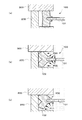
まず、図3は、フィルター付きガスケット1が最小締め代で装着された状態を示す部分断面図、図4(a)は、図3に示すガスケット本体3に均等に圧力が作用している状態の説明図、(b)は図3に示すガスケット本体3にフィルター部材2を境にして上下側で異なった圧力が加わった状態の説明図である。
ここでは、ハウジング4と、このハウジング4に突き合わされるシリンダブロック5との2部材によって、フィルター付きガスケット1の装着部6が構成されるものを示している。装着部6は、ハウジング4側のみに所定の深さで形成されている。
このフィルター付きガスケット1において、ハウジング4の装着部6の深さは、図3中の破線で示す上下のシールリップ部31を含めたガスケット本体3全体の初期状態(無加圧状態)の軸方向に沿う厚みよりも僅かに小さい程度となっている。このため、このフィルター付きガスケット1をハウジング4とシリンダブロック5とで上下から挟着すると、図3中の実線で示すように、各シールリップ部31は、ハウジング4とシリンダブロック5とに押圧されて、僅かに内周側に倒れ込むように弾性変形し、その反発力によってハウジング4とシリンダブロック5との間をシールする。
各シールリップ部31は、ガスケット本体3の内周側に配置されているため、上下から挟み付けられた際、ガスケット本体3の他の部分と少ない干渉で内周側にスムーズに倒れることができるようになっている。
そして、この状態で、図4(a)中の破線矢印に示すように、フィルター部材2を境にしてガスケット本体3の内周面31aに均等に流体の圧力P0が加わると、圧力P0は、シールリップ部31を外周側に向けて変形させるように作用する。しかし、シールリップ部31は元々装着状態で内周側に向けて倒れ込むように弾性変形しているため、外周側に向けた圧力P0を受け、ハウジング4及びシリンダブロック5に対して更に圧接される。その結果、シールリップ部31によるシール状態はより強化され、シール抜けを確実に防止する。
また、フィルター付きガスケット1は、図3中の破線で示すように、外周突起部32が装着部6の内周面6aに対して所定の締め代を有して接しているため、この外周突起部32によって装着部6の内周面6aに対してシールすると共に、ガスケット本体3が上下のシールリップ部31と外周突起部32の3点によって装着部6内に支持されるため、装着状態の姿勢を安定させることができる。
次に、図4(b)中の矢印に示すように、フィルター部材2よりも下側のガスケット本体3の内周面31aに、上側よりも大きな圧力P1が加わった場合、圧力P1によって、フィルター付きガスケット1は上方に向けて、図4(b)中の破線位置から実線位置に変位する。このフィルター付きガスケット1の上方への変位により、上側のシールリップ部31は、内周側に倒れ込んだ状態のまま、シリンダブロック5に対して更に圧接される。その結果、上側のシールリップ部31のシール状態は、図4(a)に示す均等に圧力P0が加わった場合に比べて強化される。
前述の圧力P1は、上側のシールリップ部31に比べて、下側のシールリップ部31を外周側に向けてより大きく変形させるように作用する。しかし、下側のシールリップ部31は、圧力P1によりフィルター部材2が上方に移動し、シール圧が減少しても、ハウジング4に対して圧接する。その結果、下側のシールリップ部31によるシール状態を維持することができる。
また、このように、フィルター部材2を境にして上下側で異なった圧力が加わることにより、フィルター付きガスケット1が図4(b)中の破線位置から実線位置に変位する。具体的には、下側のシールリップ部31は、外周側に向けて変形し、上側のシールリップ部31は、内周側に向けて変形する。つまり、ガスケット本体3は、フィルター部材2との固着部位を中心にして、図4(b)における時計回りに回転するような力が働く。この下側の圧力P1が過大になると、フィルター付きガスケット1が更に上方に変位することにより、下側のシールリップ部31が圧力P1を受けて外周側に倒れ込んでしまうことが想定される。
しかし、前記ガスケット本体3を回転しようとする力は、外周突起部32が装着部6の内周面6aへの当接力を高めることになり、ガスケット本体3の回転を阻止するように機能し、ガスケット本体3の姿勢を適正な状態に維持して安定したシール状態を保ち、シール抜けの発生を防止する。特に、本実施形態に示すように、外周突起部32の先端部32aが所定幅の帯状に形成されている場合、先端部32aが装着部6の内周面に当接することにより、ガスケット本体3を面で支え、ガスケット本体3の回転を効果的に阻止する機能を発揮する。これにより、ガスケット本体3の姿勢保持効果をより向上させることができる。
次に、図5は、フィルター付きガスケット1が最大締め代で装着された状態を示す部分断面図である。
この場合、ハウジング4の装着部6の深さは、図5中の破線で示す上下のシールリップ部31を含めたガスケット本体3全体の初期状態(無加圧状態)の軸方向に沿う厚みよりもかなり小さい。このため、このフィルター付きガスケット1をハウジング4とシリンダブロック5とで上下から挟着すると、図5中の実線で示すように、各シールリップ部31は、ハウジング4とシリンダブロック5とに押圧されて、内周側に大きく倒れ込むように弾性変形し、その反発力によってハウジング4とシリンダブロック5との間をシールする。この状態では、ガスケット本体3にフィルター部材2を境にして上下側で異なった圧力が加わっても、フィルター付きガスケット1が上下に変位することはほとんどないが、大きな締め代によってガスケット本体3は大きく圧縮された状態となる。
ここで、シールリップ部31は内周側に倒れ込んでおり、更に外周突起部32を有することにより、ガスケット本体3の上下外周端部と装着部6の内面との間に空隙Sが形成される。これにより、ガスケット本体3が大きく圧縮されても、装着部6の隅角部に位置するハウジング4とシリンダブロック5との突き合わせ面(図5中のA部)にガスケット本体3が噛み込まれてしまうことはない。
特に、本実施形態に示す外周突起部32は、先端部32aから上下に亘ってテーパー面32bを有しているため、空隙Sが大きく確保される。このため、ガスケット本体3が内周側から流体の過大な圧力を受けた際に、図5中の破線で示すように外周側に押圧されても、突き合わせ面に噛み込まれるおそれはない。
以上のように、本発明によるフィルター付きガスケット1によれば、差圧によってフィルター部材2を境にして上下側で異なった圧力が加わっても、シール状態を維持してシール抜けを防止できると共に、ガスケット本体3の噛み込みが生じることもない。
図6は、本発明に係るフィルター付きガスケットの他の実施形態を示す部分断面図である。
図6(a)に示すフィルター付きガスケット1は、ガスケット本体3のシールリップ部31を、上述した態様よりも外周側にずらし、ガスケット本体3の径方向のほぼ中央部に配置させたものである。このように外周側にずらした場合も、各シールリップ部31の先端は、内周側に向けて緩やかに傾くように形成されているため、2部材によって上下から挟み付けられた際、上述した態様と同様に、内周側に向けて倒れ込むように変形し、確実なシール機能を発揮することができる。
また、ガスケット本体3の外周突起部32に、先端部32aから上下に亘ってテーパー面32bを有しているため、ガスケット本体3が最大締め代で圧縮された場合でも、上記同様に噛み込みが発生するおそれはない。
図6(b)に示すフィルター付きガスケット1は、ガスケット本体3の外周面から突出する外周突起部32を、上述した山型ではなく、ガスケット本体3の軸方向の幅よりも小幅の帯状のまま突出するように形成したものである。すなわち、この外周突起部32の先端部32aは、図示するように平坦面となる断面形状であるが、この先端部32aの幅のまま、ガスケット本体3の外周面から突出した形状となっている。
この場合も、上述したように、ガスケット本体3の姿勢を適正に維持する機能を有すると共に、ガスケット本体3の内周側からフィルター部材2を境にして上下側で異なった圧力が加わっても、この外周突起部32がガスケット本体3の回転を効果的に阻止し、ガスケット本体3の適正な姿勢を維持することができる。
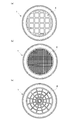
なお、上述の図1に示すフィルター付きガスケット1におけるフィルターの格子状の形状は、図7に示すごとく大きさを変更した同図(a)(b)、或いは同図(c)の蜘蛛の巣形状の他、他の形状のものを使用することができる。
1:フィルター付きガスケット
2:フィルター部材
21:網部
22:周縁部
3:ガスケット本体
31:シールリップ部
31a:内周面
31b:傾斜面
32:外周突起部
32a:先端部
32b:テーパー面
4:ハウジング
5:シリンダブロック
6:装着部
6a:内周面
2:フィルター部材
21:網部
22:周縁部
3:ガスケット本体
31:シールリップ部
31a:内周面
31b:傾斜面
32:外周突起部
32a:先端部
32b:テーパー面
4:ハウジング
5:シリンダブロック
6:装着部
6a:内周面
Claims (4)
- 網部を有するフィルター部材と、前記フィルター部材の周縁部に設けられたゴム状弾性材からなる環状のガスケット本体とからなり、
前記ガスケット本体の上下面に、上下から挟着された際に内周側に向けて倒れる環状のシールリップ部がそれぞれ形成されていると共に、
前記ガスケット本体の外周面に、装着部の内周面と所定の締め代を有して接する外周突起部が、前記ガスケット本体の径方向に突出するように形成されていることを特徴とするフィルター付きガスケット。 - 前記シールリップ部は、前記ガスケット本体の内周端側の上下面にそれぞれ形成されていることを特徴とする請求項1記載のフィルター付きガスケット。
- 前記外周突起部の先端部は、前記ガスケット本体の軸方向幅よりも小幅に形成されていることを特徴とする請求項1又は2記載のフィルター付きガスケット。
- 前記外周突起部は、先端部から前記ガスケット本体の上下面にかけて傾斜するテーパー面を有していることを特徴とする請求項1、2又は3記載のフィルター付きガスケット。
Priority Applications (1)
| Application Number | Priority Date | Filing Date | Title |
|---|---|---|---|
| JP2017521605A JP6796062B2 (ja) | 2015-11-06 | 2016-10-18 | フィルター付きガスケット |
Applications Claiming Priority (2)
| Application Number | Priority Date | Filing Date | Title |
|---|---|---|---|
| JP2015-218672 | 2015-11-06 | ||
| JP2015218672 | 2015-11-06 |
Publications (1)
| Publication Number | Publication Date |
|---|---|
| WO2017077855A1 true WO2017077855A1 (ja) | 2017-05-11 |
Family
ID=58662528
Family Applications (1)
| Application Number | Title | Priority Date | Filing Date |
|---|---|---|---|
| PCT/JP2016/080823 Ceased WO2017077855A1 (ja) | 2015-11-06 | 2016-10-18 | フィルター付きガスケット |
Country Status (2)
| Country | Link |
|---|---|
| JP (1) | JP6796062B2 (ja) |
| WO (1) | WO2017077855A1 (ja) |
Cited By (2)
| Publication number | Priority date | Publication date | Assignee | Title |
|---|---|---|---|---|
| JP2018091352A (ja) * | 2016-11-30 | 2018-06-14 | Nok株式会社 | フィルター付きガスケット |
| CN114870535A (zh) * | 2022-04-24 | 2022-08-09 | 合肥品炙装备科技有限公司 | 一种新型真空过滤颗粒装置 |
Citations (2)
| Publication number | Priority date | Publication date | Assignee | Title |
|---|---|---|---|---|
| JPH0643421U (ja) * | 1992-11-25 | 1994-06-10 | リンナイ株式会社 | 弁装置用シールパッキン |
| JP2013245798A (ja) * | 2012-05-29 | 2013-12-09 | Nok Corp | フィルター付きガスケット |
-
2016
- 2016-10-18 JP JP2017521605A patent/JP6796062B2/ja active Active
- 2016-10-18 WO PCT/JP2016/080823 patent/WO2017077855A1/ja not_active Ceased
Patent Citations (2)
| Publication number | Priority date | Publication date | Assignee | Title |
|---|---|---|---|---|
| JPH0643421U (ja) * | 1992-11-25 | 1994-06-10 | リンナイ株式会社 | 弁装置用シールパッキン |
| JP2013245798A (ja) * | 2012-05-29 | 2013-12-09 | Nok Corp | フィルター付きガスケット |
Cited By (2)
| Publication number | Priority date | Publication date | Assignee | Title |
|---|---|---|---|---|
| JP2018091352A (ja) * | 2016-11-30 | 2018-06-14 | Nok株式会社 | フィルター付きガスケット |
| CN114870535A (zh) * | 2022-04-24 | 2022-08-09 | 合肥品炙装备科技有限公司 | 一种新型真空过滤颗粒装置 |
Also Published As
| Publication number | Publication date |
|---|---|
| JP6796062B2 (ja) | 2020-12-02 |
| JPWO2017077855A1 (ja) | 2018-08-16 |
Similar Documents
| Publication | Publication Date | Title |
|---|---|---|
| US10612660B2 (en) | Gasket | |
| JP6033996B1 (ja) | 密封装置 | |
| CN108291650B (zh) | 密封装置 | |
| JP6263255B2 (ja) | 密封装置 | |
| US20150097344A1 (en) | Sealing Device | |
| JP2013522551A (ja) | 改善されたシール要素接合部を有する低トルクシャフトシール | |
| WO2017154615A1 (ja) | ガスケット及び密封装置 | |
| KR20150133636A (ko) | 축 시일 | |
| WO2017077855A1 (ja) | フィルター付きガスケット | |
| WO2016143397A1 (ja) | 密封装置 | |
| JP2017106528A (ja) | 密封装置 | |
| JP2016061321A (ja) | 密封装置 | |
| KR101900394B1 (ko) | 밀봉 링 | |
| JP7038619B2 (ja) | 密封装置 | |
| JP2017089801A (ja) | デフサイド用の密封装置 | |
| JP7177195B2 (ja) | ガスケット及び密封装置 | |
| JP4324782B2 (ja) | 密封装置 | |
| JPWO2013038989A1 (ja) | 密封装置 | |
| JP2018004027A (ja) | 密封装置 | |
| TWI701401B (zh) | 密封材之配置構造 | |
| JP3199250U (ja) | リップ付樹脂カバーシール | |
| JP6570931B2 (ja) | 密封装置 | |
| JP6860306B2 (ja) | ガスケット及び密封装置 | |
| JP6115099B2 (ja) | 密封装置 | |
| JP5444841B2 (ja) | 密封装置 |
Legal Events
| Date | Code | Title | Description |
|---|---|---|---|
| ENP | Entry into the national phase |
Ref document number: 2017521605 Country of ref document: JP Kind code of ref document: A |
|
| 121 | Ep: the epo has been informed by wipo that ep was designated in this application |
Ref document number: 16861921 Country of ref document: EP Kind code of ref document: A1 |
|
| NENP | Non-entry into the national phase |
Ref country code: DE |
|
| 122 | Ep: pct application non-entry in european phase |
Ref document number: 16861921 Country of ref document: EP Kind code of ref document: A1 |