WO2017073208A1 - 車両の前部構造 - Google Patents
車両の前部構造 Download PDFInfo
- Publication number
- WO2017073208A1 WO2017073208A1 PCT/JP2016/077875 JP2016077875W WO2017073208A1 WO 2017073208 A1 WO2017073208 A1 WO 2017073208A1 JP 2016077875 W JP2016077875 W JP 2016077875W WO 2017073208 A1 WO2017073208 A1 WO 2017073208A1
- Authority
- WO
- WIPO (PCT)
- Prior art keywords
- vehicle
- headlamp
- cover member
- width direction
- vehicle front
- Prior art date
- Legal status (The legal status is an assumption and is not a legal conclusion. Google has not performed a legal analysis and makes no representation as to the accuracy of the status listed.)
- Ceased
Links
Images






Classifications
-
- F—MECHANICAL ENGINEERING; LIGHTING; HEATING; WEAPONS; BLASTING
- F21—LIGHTING
- F21S—NON-PORTABLE LIGHTING DEVICES; SYSTEMS THEREOF; VEHICLE LIGHTING DEVICES SPECIALLY ADAPTED FOR VEHICLE EXTERIORS
- F21S41/00—Illuminating devices specially adapted for vehicle exteriors, e.g. headlamps
- F21S41/10—Illuminating devices specially adapted for vehicle exteriors, e.g. headlamps characterised by the light source
- F21S41/14—Illuminating devices specially adapted for vehicle exteriors, e.g. headlamps characterised by the light source characterised by the type of light source
- F21S41/141—Light emitting diodes [LED]
- F21S41/151—Light emitting diodes [LED] arranged in one or more lines
- F21S41/153—Light emitting diodes [LED] arranged in one or more lines arranged in a matrix
-
- B—PERFORMING OPERATIONS; TRANSPORTING
- B60—VEHICLES IN GENERAL
- B60Q—ARRANGEMENT OF SIGNALLING OR LIGHTING DEVICES, THE MOUNTING OR SUPPORTING THEREOF OR CIRCUITS THEREFOR, FOR VEHICLES IN GENERAL
- B60Q1/00—Arrangement of optical signalling or lighting devices, the mounting or supporting thereof or circuits therefor
- B60Q1/0088—Details of electrical connections
- B60Q1/0094—Arrangement of electronic circuits separated from the light source, e.g. mounting of housings for starter circuits for discharge lamps
-
- B—PERFORMING OPERATIONS; TRANSPORTING
- B60—VEHICLES IN GENERAL
- B60Q—ARRANGEMENT OF SIGNALLING OR LIGHTING DEVICES, THE MOUNTING OR SUPPORTING THEREOF OR CIRCUITS THEREFOR, FOR VEHICLES IN GENERAL
- B60Q1/00—Arrangement of optical signalling or lighting devices, the mounting or supporting thereof or circuits therefor
- B60Q1/02—Arrangement of optical signalling or lighting devices, the mounting or supporting thereof or circuits therefor the devices being primarily intended to illuminate the way ahead or to illuminate other areas of way or environments
- B60Q1/04—Arrangement of optical signalling or lighting devices, the mounting or supporting thereof or circuits therefor the devices being primarily intended to illuminate the way ahead or to illuminate other areas of way or environments the devices being headlights
-
- B—PERFORMING OPERATIONS; TRANSPORTING
- B60—VEHICLES IN GENERAL
- B60Q—ARRANGEMENT OF SIGNALLING OR LIGHTING DEVICES, THE MOUNTING OR SUPPORTING THEREOF OR CIRCUITS THEREFOR, FOR VEHICLES IN GENERAL
- B60Q1/00—Arrangement of optical signalling or lighting devices, the mounting or supporting thereof or circuits therefor
- B60Q1/02—Arrangement of optical signalling or lighting devices, the mounting or supporting thereof or circuits therefor the devices being primarily intended to illuminate the way ahead or to illuminate other areas of way or environments
- B60Q1/04—Arrangement of optical signalling or lighting devices, the mounting or supporting thereof or circuits therefor the devices being primarily intended to illuminate the way ahead or to illuminate other areas of way or environments the devices being headlights
- B60Q1/06—Arrangement of optical signalling or lighting devices, the mounting or supporting thereof or circuits therefor the devices being primarily intended to illuminate the way ahead or to illuminate other areas of way or environments the devices being headlights adjustable, e.g. remotely-controlled from inside vehicle
- B60Q1/068—Arrangement of optical signalling or lighting devices, the mounting or supporting thereof or circuits therefor the devices being primarily intended to illuminate the way ahead or to illuminate other areas of way or environments the devices being headlights adjustable, e.g. remotely-controlled from inside vehicle by mechanical means
-
- B—PERFORMING OPERATIONS; TRANSPORTING
- B60—VEHICLES IN GENERAL
- B60Q—ARRANGEMENT OF SIGNALLING OR LIGHTING DEVICES, THE MOUNTING OR SUPPORTING THEREOF OR CIRCUITS THEREFOR, FOR VEHICLES IN GENERAL
- B60Q1/00—Arrangement of optical signalling or lighting devices, the mounting or supporting thereof or circuits therefor
- B60Q1/02—Arrangement of optical signalling or lighting devices, the mounting or supporting thereof or circuits therefor the devices being primarily intended to illuminate the way ahead or to illuminate other areas of way or environments
- B60Q1/04—Arrangement of optical signalling or lighting devices, the mounting or supporting thereof or circuits therefor the devices being primarily intended to illuminate the way ahead or to illuminate other areas of way or environments the devices being headlights
- B60Q1/06—Arrangement of optical signalling or lighting devices, the mounting or supporting thereof or circuits therefor the devices being primarily intended to illuminate the way ahead or to illuminate other areas of way or environments the devices being headlights adjustable, e.g. remotely-controlled from inside vehicle
- B60Q1/08—Arrangement of optical signalling or lighting devices, the mounting or supporting thereof or circuits therefor the devices being primarily intended to illuminate the way ahead or to illuminate other areas of way or environments the devices being headlights adjustable, e.g. remotely-controlled from inside vehicle automatically
-
- F—MECHANICAL ENGINEERING; LIGHTING; HEATING; WEAPONS; BLASTING
- F21—LIGHTING
- F21S—NON-PORTABLE LIGHTING DEVICES; SYSTEMS THEREOF; VEHICLE LIGHTING DEVICES SPECIALLY ADAPTED FOR VEHICLE EXTERIORS
- F21S41/00—Illuminating devices specially adapted for vehicle exteriors, e.g. headlamps
- F21S41/10—Illuminating devices specially adapted for vehicle exteriors, e.g. headlamps characterised by the light source
- F21S41/14—Illuminating devices specially adapted for vehicle exteriors, e.g. headlamps characterised by the light source characterised by the type of light source
- F21S41/141—Light emitting diodes [LED]
- F21S41/143—Light emitting diodes [LED] the main emission direction of the LED being parallel to the optical axis of the illuminating device
-
- F—MECHANICAL ENGINEERING; LIGHTING; HEATING; WEAPONS; BLASTING
- F21—LIGHTING
- F21S—NON-PORTABLE LIGHTING DEVICES; SYSTEMS THEREOF; VEHICLE LIGHTING DEVICES SPECIALLY ADAPTED FOR VEHICLE EXTERIORS
- F21S41/00—Illuminating devices specially adapted for vehicle exteriors, e.g. headlamps
- F21S41/10—Illuminating devices specially adapted for vehicle exteriors, e.g. headlamps characterised by the light source
- F21S41/19—Attachment of light sources or lamp holders
-
- F—MECHANICAL ENGINEERING; LIGHTING; HEATING; WEAPONS; BLASTING
- F21—LIGHTING
- F21S—NON-PORTABLE LIGHTING DEVICES; SYSTEMS THEREOF; VEHICLE LIGHTING DEVICES SPECIALLY ADAPTED FOR VEHICLE EXTERIORS
- F21S41/00—Illuminating devices specially adapted for vehicle exteriors, e.g. headlamps
- F21S41/20—Illuminating devices specially adapted for vehicle exteriors, e.g. headlamps characterised by refractors, transparent cover plates, light guides or filters
- F21S41/25—Projection lenses
- F21S41/255—Lenses with a front view of circular or truncated circular outline
-
- F—MECHANICAL ENGINEERING; LIGHTING; HEATING; WEAPONS; BLASTING
- F21—LIGHTING
- F21S—NON-PORTABLE LIGHTING DEVICES; SYSTEMS THEREOF; VEHICLE LIGHTING DEVICES SPECIALLY ADAPTED FOR VEHICLE EXTERIORS
- F21S41/00—Illuminating devices specially adapted for vehicle exteriors, e.g. headlamps
- F21S41/20—Illuminating devices specially adapted for vehicle exteriors, e.g. headlamps characterised by refractors, transparent cover plates, light guides or filters
- F21S41/28—Cover glass
-
- F—MECHANICAL ENGINEERING; LIGHTING; HEATING; WEAPONS; BLASTING
- F21—LIGHTING
- F21S—NON-PORTABLE LIGHTING DEVICES; SYSTEMS THEREOF; VEHICLE LIGHTING DEVICES SPECIALLY ADAPTED FOR VEHICLE EXTERIORS
- F21S41/00—Illuminating devices specially adapted for vehicle exteriors, e.g. headlamps
- F21S41/30—Illuminating devices specially adapted for vehicle exteriors, e.g. headlamps characterised by reflectors
- F21S41/32—Optical layout thereof
-
- F—MECHANICAL ENGINEERING; LIGHTING; HEATING; WEAPONS; BLASTING
- F21—LIGHTING
- F21S—NON-PORTABLE LIGHTING DEVICES; SYSTEMS THEREOF; VEHICLE LIGHTING DEVICES SPECIALLY ADAPTED FOR VEHICLE EXTERIORS
- F21S41/00—Illuminating devices specially adapted for vehicle exteriors, e.g. headlamps
- F21S41/60—Illuminating devices specially adapted for vehicle exteriors, e.g. headlamps characterised by a variable light distribution
- F21S41/65—Illuminating devices specially adapted for vehicle exteriors, e.g. headlamps characterised by a variable light distribution by acting on light sources
- F21S41/657—Illuminating devices specially adapted for vehicle exteriors, e.g. headlamps characterised by a variable light distribution by acting on light sources by moving light sources
-
- F—MECHANICAL ENGINEERING; LIGHTING; HEATING; WEAPONS; BLASTING
- F21—LIGHTING
- F21S—NON-PORTABLE LIGHTING DEVICES; SYSTEMS THEREOF; VEHICLE LIGHTING DEVICES SPECIALLY ADAPTED FOR VEHICLE EXTERIORS
- F21S43/00—Signalling devices specially adapted for vehicle exteriors, e.g. brake lamps, direction indicator lights or reversing lights
- F21S43/10—Signalling devices specially adapted for vehicle exteriors, e.g. brake lamps, direction indicator lights or reversing lights characterised by the light source
- F21S43/13—Signalling devices specially adapted for vehicle exteriors, e.g. brake lamps, direction indicator lights or reversing lights characterised by the light source characterised by the type of light source
- F21S43/14—Light emitting diodes [LED]
-
- F—MECHANICAL ENGINEERING; LIGHTING; HEATING; WEAPONS; BLASTING
- F21—LIGHTING
- F21S—NON-PORTABLE LIGHTING DEVICES; SYSTEMS THEREOF; VEHICLE LIGHTING DEVICES SPECIALLY ADAPTED FOR VEHICLE EXTERIORS
- F21S43/00—Signalling devices specially adapted for vehicle exteriors, e.g. brake lamps, direction indicator lights or reversing lights
- F21S43/10—Signalling devices specially adapted for vehicle exteriors, e.g. brake lamps, direction indicator lights or reversing lights characterised by the light source
- F21S43/13—Signalling devices specially adapted for vehicle exteriors, e.g. brake lamps, direction indicator lights or reversing lights characterised by the light source characterised by the type of light source
- F21S43/15—Strips of light sources
-
- F—MECHANICAL ENGINEERING; LIGHTING; HEATING; WEAPONS; BLASTING
- F21—LIGHTING
- F21S—NON-PORTABLE LIGHTING DEVICES; SYSTEMS THEREOF; VEHICLE LIGHTING DEVICES SPECIALLY ADAPTED FOR VEHICLE EXTERIORS
- F21S43/00—Signalling devices specially adapted for vehicle exteriors, e.g. brake lamps, direction indicator lights or reversing lights
- F21S43/30—Signalling devices specially adapted for vehicle exteriors, e.g. brake lamps, direction indicator lights or reversing lights characterised by reflectors
- F21S43/31—Optical layout thereof
-
- F—MECHANICAL ENGINEERING; LIGHTING; HEATING; WEAPONS; BLASTING
- F21—LIGHTING
- F21S—NON-PORTABLE LIGHTING DEVICES; SYSTEMS THEREOF; VEHICLE LIGHTING DEVICES SPECIALLY ADAPTED FOR VEHICLE EXTERIORS
- F21S45/00—Arrangements within vehicle lighting devices specially adapted for vehicle exteriors, for purposes other than emission or distribution of light
- F21S45/40—Cooling of lighting devices
- F21S45/47—Passive cooling, e.g. using fins, thermal conductive elements or openings
-
- F—MECHANICAL ENGINEERING; LIGHTING; HEATING; WEAPONS; BLASTING
- F21—LIGHTING
- F21S—NON-PORTABLE LIGHTING DEVICES; SYSTEMS THEREOF; VEHICLE LIGHTING DEVICES SPECIALLY ADAPTED FOR VEHICLE EXTERIORS
- F21S45/00—Arrangements within vehicle lighting devices specially adapted for vehicle exteriors, for purposes other than emission or distribution of light
- F21S45/40—Cooling of lighting devices
- F21S45/49—Attachment of the cooling means
-
- F—MECHANICAL ENGINEERING; LIGHTING; HEATING; WEAPONS; BLASTING
- F21—LIGHTING
- F21V—FUNCTIONAL FEATURES OR DETAILS OF LIGHTING DEVICES OR SYSTEMS THEREOF; STRUCTURAL COMBINATIONS OF LIGHTING DEVICES WITH OTHER ARTICLES, NOT OTHERWISE PROVIDED FOR
- F21V29/00—Protecting lighting devices from thermal damage; Cooling or heating arrangements specially adapted for lighting devices or systems
- F21V29/50—Cooling arrangements
- F21V29/70—Cooling arrangements characterised by passive heat-dissipating elements, e.g. heat-sinks
- F21V29/74—Cooling arrangements characterised by passive heat-dissipating elements, e.g. heat-sinks with fins or blades
-
- F—MECHANICAL ENGINEERING; LIGHTING; HEATING; WEAPONS; BLASTING
- F21—LIGHTING
- F21V—FUNCTIONAL FEATURES OR DETAILS OF LIGHTING DEVICES OR SYSTEMS THEREOF; STRUCTURAL COMBINATIONS OF LIGHTING DEVICES WITH OTHER ARTICLES, NOT OTHERWISE PROVIDED FOR
- F21V29/00—Protecting lighting devices from thermal damage; Cooling or heating arrangements specially adapted for lighting devices or systems
- F21V29/50—Cooling arrangements
- F21V29/70—Cooling arrangements characterised by passive heat-dissipating elements, e.g. heat-sinks
- F21V29/83—Cooling arrangements characterised by passive heat-dissipating elements, e.g. heat-sinks the elements having apertures, ducts or channels, e.g. heat radiation holes
-
- B—PERFORMING OPERATIONS; TRANSPORTING
- B62—LAND VEHICLES FOR TRAVELLING OTHERWISE THAN ON RAILS
- B62D—MOTOR VEHICLES; TRAILERS
- B62D35/00—Vehicle bodies characterised by streamlining
-
- F—MECHANICAL ENGINEERING; LIGHTING; HEATING; WEAPONS; BLASTING
- F21—LIGHTING
- F21W—INDEXING SCHEME ASSOCIATED WITH SUBCLASSES F21K, F21L, F21S and F21V, RELATING TO USES OR APPLICATIONS OF LIGHTING DEVICES OR SYSTEMS
- F21W2102/00—Exterior vehicle lighting devices for illuminating purposes
- F21W2102/10—Arrangement or contour of the emitted light
- F21W2102/17—Arrangement or contour of the emitted light for regions other than high beam or low beam
- F21W2102/19—Arrangement or contour of the emitted light for regions other than high beam or low beam for curves
-
- F—MECHANICAL ENGINEERING; LIGHTING; HEATING; WEAPONS; BLASTING
- F21—LIGHTING
- F21W—INDEXING SCHEME ASSOCIATED WITH SUBCLASSES F21K, F21L, F21S and F21V, RELATING TO USES OR APPLICATIONS OF LIGHTING DEVICES OR SYSTEMS
- F21W2103/00—Exterior vehicle lighting devices for signalling purposes
- F21W2103/15—Side marker lights
-
- F—MECHANICAL ENGINEERING; LIGHTING; HEATING; WEAPONS; BLASTING
- F21—LIGHTING
- F21Y—INDEXING SCHEME ASSOCIATED WITH SUBCLASSES F21K, F21L, F21S and F21V, RELATING TO THE FORM OR THE KIND OF THE LIGHT SOURCES OR OF THE COLOUR OF THE LIGHT EMITTED
- F21Y2115/00—Light-generating elements of semiconductor light sources
- F21Y2115/10—Light-emitting diodes [LED]
Definitions
- the present disclosure relates to a vehicle front structure in which vehicle front lights are provided at both ends in the vehicle width direction of the vehicle front.
- headlamp units are provided with an accompanying structure such as an AFS driving device (an active front lighting system or an LED heat sink for cooling an LED used as a light source), and the size of the headlamp unit tends to increase. It is in.
- AFS driving device an active front lighting system or an LED heat sink for cooling an LED used as a light source
- the AFS driving device is a driving device that changes the trading company direction of the headlamps according to the traveling state of the vehicle.
- the headlamp unit will be further enlarged. Therefore, it is difficult to shorten the front and rear length of the headlamp unit.
- Patent Document 1 discloses a headlamp unit in which an accessory lamp and an AFS driving device are incorporated in an LED headlamp.
- an LED comprising a heat radiation fin is disclosed.
- the heat sink and AFS drive device are arranged in the vehicle width direction and the vehicle lower direction, and the front and rear length of the vehicle front light (head lamp unit) cannot be shortened sufficiently, so that the short overhang can be achieved. There was room for further improvement.
- An object of the present invention is to provide a vehicle front structure capable of achieving the above.
- the vehicle front structure includes vehicle front lights at both ends in the vehicle width direction of the vehicle front.
- the vehicle front lamp includes a headlamp, a cover member, and a lamp auxiliary machine.
- the cover member is disposed above the headlamp.
- the light auxiliary machine is disposed above the rear part of the headlamp and below the cover member.
- the vehicle front lamp in the present aspect, it is formed below the cover member and outside in the vehicle width direction or inside in the vehicle width direction of the headlamp, and the traveling wind from the front of the vehicle is There is a ventilation path that can pass through.
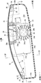
- FIG. 1 is a schematic perspective view showing a configuration of a vehicle 100 according to an embodiment from the left front. 1 is a schematic perspective view showing the configuration of a vehicle 100 from the left rear. 2 is a schematic cross-sectional view showing a configuration of a headlamp unit 21 in a vehicle 100.
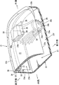
- FIG. FIG. 4 is a diagram taken along the line IV-IV in FIG. 3, and is a schematic perspective view showing a configuration of a headlamp unit 21.
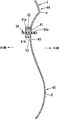
- FIG. 5 is a cross-sectional view taken along line VV in FIG. 3, and is a schematic cross-sectional view showing a partial configuration of a headlamp unit 21.
- FIG. 3 is a cross-sectional view taken along line VI-VI in FIG.
- FIG. 2 is a schematic cross-sectional view illustrating a partial configuration of a front fender 3 and a side door 11 in a vehicle 100.
- FIG. 3 is a cross-sectional view taken along the line VII-VII in FIG. 2, and is a schematic cross-sectional view illustrating a partial configuration of the front fender 3 and the side door 11 in the vehicle 100.
- 4 is a schematic side view showing a configuration of a protruding member 50 attached to the front fender 3.
- FIG. FIG. 9 is a cross-sectional view taken along the line IX-IX in FIG. 8, and is a schematic cross-sectional view illustrating a concave portion 40 and a peripheral configuration in the front fender 3.
- FIG. 9 is a cross-sectional view taken along the line XX of FIG.
- FIG. 9 is a cross-sectional view taken along the line XI-XI in FIG. 8, and is a schematic cross-sectional view illustrating a mounting structure of the protruding member 50 to the front fender 3.
- FIG. 1 is a schematic perspective view showing the configuration of the vehicle 100 from the left front
- FIG. 2 is a schematic perspective view showing the configuration of the vehicle 100 from the left rear.
- the upper part of the engine room 1 located in the front part of the vehicle 100 is covered with a bonnet 2.
- the left and right sides of the engine room 1 are covered with front fenders (specifically, front fender panels) 3 and 3.
- the front portion of the engine room 1 is covered with a front bumper face 5 having a front grill 4.
- a lower stiffener 6 is provided below the front bumper face 5.
- the lower stiffener 6 is a so-called foot wiping member, and is a member that prevents a secondary collision by tilting the pedestrian onto the hood 2 by performing leg wiping of the pedestrian at the time of collision with the pedestrian. It is.
- the front fender 3 has a wheel arch portion 8 corresponding to the front wheel 7.
- Side doors 11 are provided at the rear of the left and right front fenders 3 and 3.
- the side door 11 is provided with a door mirror 9 and a door outer handle 10.
- a rear fender 12 is provided at the rear of the side door 11.
- the rear fender 12 has a wheel arch portion 14 corresponding to the rear wheel 13.
- a front window glass 15 is provided at the rear end of the engine room 1, and front pillars 16 are provided on both sides of the front window glass 15 in the vehicle width direction.
- a rear pillar 17 is provided behind the window of the side door 11, and the upper part of the passenger compartment is covered with a roof part 18. Further, a tail lamp 19 and a rear spoiler 20 are provided at both ends of the vehicle 100 in the vehicle width direction.
- FIG. 3 is a schematic cross-sectional view showing the configuration of the headlamp unit (vehicle front lamp) in the vehicle 100
- FIG. 4 shows the configuration of the headlamp unit 21 in a state cut along line IV-IV in FIG.
- FIG. 5 is a schematic perspective view
- FIG. 5 is a schematic cross-sectional view showing a partial configuration of the headlamp unit 21 in a state cut along line VV in FIG.
- a headlamp unit 21 which is a partial lamp is provided.
- the headlamp unit 21 includes a headlight as a headlamp in an internal space formed by a cover member 22 positioned on the upper side and a headlamp unit case 23 positioned on the lower side.
- a lamp 24, an AFS actuator 25, and a controller 26 are provided.
- the cover member 22 disposed above the headlamp 24 forms a design surface that is continuous with the front end portion of the front fender 3. As shown in FIGS. 1 and 4, the rear end of the cover member 22 is formed. The front end 22a of the cover member 22 is formed so as to be positioned on the lower front side with respect to 22b.
- the headlamp unit case 23 is made of synthetic resin, and stands upward from the bottom wall 23a, side walls 23b and 23c rising upward from both sides in the vehicle width direction of the bottom wall 23a, and the rear end of the bottom wall 23a. And a rear wall 23d that rises.
- the bottom wall 23a, the side walls 23b and 23c, and the rear wall 23d are continuous.
- a rear opening 23e is formed in the rear wall 23d as an opening so as to include the position of the headlamp 24 when viewed from the front.
- the side wall 23c on the inner side in the vehicle width direction is formed such that the front end 23c1 is located on the inner side in the vehicle width direction with respect to the rear end 23c2.
- the side wall 23c is formed with a smooth curved surface so as to be gradually located on the outer side in the vehicle width direction from the front end 23c1 to the rear end 23c2.
- the front end of the headlamp unit 21 is formed with a front opening 23 f as an opening surrounded by the front end of the headlamp unit case 23 and the front end 22 a of the cover member 22.
- the length of the front opening 23f in the vehicle width direction is significantly longer than the length of the rear opening 23e in the vehicle width direction.
- a front opening 23f and a rear opening 23e are communicated in the vehicle front-rear direction below the cover member 22 and inside the headlamp 24 in the vehicle width direction.
- Ventilation path 27 through which the traveling wind from the vehicle can pass toward the rear of the vehicle is formed. Note that the ventilation path 27 may be formed outward of the headlamp 24 in the vehicle width direction.
- the headlamp 24 includes a plurality of LEDs 24a as a light source, an outer lens 24b, and a lamp housing 24c.
- heat radiating fins 24d are provided on the outer peripheral portion of the lamp housing 24c as air cooling means that extend in the vehicle front-rear direction and are at least partially disposed in the ventilation path 27.
- the AFS actuator 25 (active front lighting system actuator) is attached to a support member 28 fixed to the rear wall 23d of the headlamp unit case 23, and is arranged to be positioned above the rear portion of the headlamp 24. .
- the AFS actuator 25 changes the irradiation direction of the headlamp 24 according to the traveling state of the vehicle.
- the rotation output shaft 29 of the AFS actuator 25 passes through the support member 28 and is fitted to the upper portion of the lamp housing 24c.
- a rotation center shaft 30 is provided below the lamp housing 24 c so as to coincide with the axis of the rotation output shaft 29, and the irradiation direction of the headlamp 24 is centered on the rotation output shaft 29 and the rotation center shaft 30. It is configured to be changed.
- the rotation center shaft 30 is rotatably supported on the bottom wall 23 a of the headlamp unit case 23.
- the controller 26 controls the lighting circuit of the headlamp 24 and an illumination lamp unit 31 described later, and the AFS actuator 25.
- the controller 26 is provided above the AFS actuator 25, and is disposed so that the controller 26 is located above the rear part of the headlamp 24.
- the AFS actuator 25 and the controller 26 are lighting accessories, which are arranged above the rear part of the headlamp 24.
- the cover member 22 is disposed above the headlamp 24, and the ventilation path 27 through which the traveling wind from the front of the vehicle can pass is located below the cover member 22 and inward in the vehicle width direction of the headlamp 24.
- An AFS actuator 25 and a controller 26 are disposed above the rear part of the headlamp 24 as a lighting auxiliary machine.
- the front and rear length of the headlamp unit 21 is shortened, and traveling wind passes below the cover member 22 and inside the headlamp 24 in the vehicle width direction.
- a possible ventilation path 27 is formed, and the headlamp 24 and the lighting auxiliary machine are cooled by the traveling wind passing through the ventilation path 27.
- the headlamp unit 21 is configured to improve the flexibility of the vehicle layout and shorten the front overhang by simultaneously reducing the front and rear length of the headlamp unit 21 and ensuring the cooling performance.
- the AFS actuator 25 as the lighting auxiliary device, the controller 26, and the headlamp 24 as the headlamp are provided with a plurality of radiating fins 25a, 26a, and 24d as air cooling means.
- These radiation fins 25a, 26a, 24d extend in the vehicle front-rear direction, and at least a part of each radiation fin 25a, 26a, 24d is disposed in the ventilation path 27.
- the temperature of the LED 24a of the headlamp 24, the AFS actuator 25, and the controller 26 is effectively reduced by air cooling.
- the AFS actuator 25, the controller 26, and the headlamp 24 are all provided with the radiation fins 25a, 26a, and 24d.
- the radiation fins are selectively provided. It is good also as providing.
- the vehicle around the cover member 22 passes through the periphery of the cover member 22, specifically, from the inner periphery in the vehicle width direction of the cover member 22 to the rear periphery in the vehicle longitudinal direction of the cover member 22.
- An illumination lamp unit 31 is provided around the outer periphery in the width direction.
- the illumination lamp unit 31 includes a plurality of LEDs 32 as a light emitting unit, a printed wiring board 33, a housing 34, a lens 35, and a reflector 36.
- the plurality of LEDs 32 are arranged at an arbitrary interval or an equal interval from the outer periphery of the cover member 22, specifically, from the inner periphery in the vehicle width direction of the cover member 22 to the outer periphery in the vehicle width direction through the rear outer periphery in the vehicle front-rear direction.
- the printed wiring board 33 is a board that is disposed at the lower periphery of the cover member 22 and electrically connects the LED 32.
- the housing 34 surrounds the printed wiring board 33.
- the lens 35 is located above the plurality of LEDs 32 and is disposed flush with the upper surface of the peripheral edge of the cover member 22.
- the reflector 36 has a substantially L-shaped cross section and is positioned below and on the outer periphery of the plurality of LEDs 32.
- a plurality of LEDs 32 are arranged on the outer periphery of the cover member 22, and a printed wiring board 33 and a housing 34 as auxiliary devices of the LEDs 32 are arranged at the lower part of the cover member 22.
- a printed wiring board 33 and a housing 34 are compactly arranged below the member 22 so as to improve layout while ensuring layout.
- the illumination lamp unit 31 can be used as a vehicle width lamp.
- the headlamp 24 is supported on the bottom wall 23 a of the headlamp unit case 23 via the rotation center shaft 30. Further, the controller 26 and the AFS actuator 25 as a lighting auxiliary machine are supported on the rear wall 23 d of the headlamp unit case 23 via a support member 28.
- the cover member 22 is supported by the housing 34.
- a printed wiring board 33 and a housing 34 which are auxiliary devices of the light emitting unit (see LED 32) are supported by the headlamp unit case 23 via a reflector 36.
- the headlamp 24, the cover member 22, the controller 26, the AFS actuator 25, the printed wiring board 33, and the housing 34 are integrally assembled to ensure the mountability of the headlamp unit 21 on the vehicle and each component. It is configured so as to achieve compatibility with ensuring the assembly accuracy.
- FIG. 6 is a schematic cross-sectional view taken along line VI-VI in FIG. 2
- FIG. 7 is a schematic cross-sectional view taken along line VII-VII in FIG. 2
- FIG. 8 is a schematic side view of FIG. 9 is a schematic cross-sectional view taken along the line IX-IX of FIG. 8
- FIG. 10 is a schematic cross-sectional view taken along the line XX of FIG. 8
- FIG. FIG. 8 is a schematic cross-sectional view taken along line XI-XI.
- a concave portion 40 formed inwardly in a concave shape is provided.
- the concave portion 40 has a concave shape that is recessed with a smooth curved surface inward in the vehicle width direction when viewed in cross section.
- the front wheel 7 in the concave portion 40 extends in the front-rear direction of the vehicle at a height position substantially equal to the vicinity of the upper end position of the front wheel 7 (the normal front wheel that has not bounced or rebounded).
- An opening 41 penetrating the inside and outside of the front fender 3 in the vehicle width direction is provided.
- the side door 11 (refer FIG. 6, FIG. 7) is provided in the rear part of the front fender 3. As shown in FIG. The side door 11 is obtained by integrating a door outer panel 11a and a door inner panel 11b by hemming.
- the recessed portion 40 extends further to the rear of the vehicle than the opening 41. That is, as shown in FIG. 6 and the like, an extended recess 42 is formed by recessing the door outer panel 11a of the side door 11 inwardly in the vehicle width direction with a smooth curved surface in a vehicle plan view and a vehicle front view. Has been.
- the opening 41 and the rear opening 23 e of the headlamp unit 21 are communicated with each other by a side duct 43.
- a through hole 43 a facing the inside of the engine room 1 is formed on the inner surface of the side duct 43 in the vehicle width direction.
- the recessed portion 40 and the extended recessed portion 42 are recessed inward in the vehicle width direction with a smooth curved surface, both in the vehicle plan view and the vehicle front view.
- the three-dimensional negative pressure is generated by the turbulent flow (a).
- the concave portion 40 is provided with an opening 41 that penetrates the front fender 3 in and out in the vehicle width direction. Further, the side door 11 is formed with an extending recess 42 in which the recessed portion 40 extends rearward from the opening 41. Thereby, in the vehicle 100, the three-dimensional negative pressure generated in the concave portion 40 is effectively used to improve the airflow sucking property such as hot air from the inside of the front fender 3.
- the airflow that has been heated by the running air flowing into the ventilation path 27 from the front opening 23f of the headlamp unit 21 and air-cooled the headlamp 24, the AFS actuator 25, and the controller 26 passes through the side duct 23e.
- 43 flows into the side duct 43 through the through-hole 43a, and the airflow flowing down in the side duct 43 flows into the side fender 3 due to the negative pressure described above. It is configured to be discharged from the opening 41 to the outside of the vehicle.
- the concave portion 40 and the extended concave portion 42 are recessed with a smooth curved surface inward in the vehicle width direction when viewed from the front of the vehicle. It forms so that 42 may decrease, so that 42 goes to a vehicle rear. Specifically, it is formed so that the vertical dimension of the above-described extending recess 42 decreases as the vehicle moves rearward. Thereby, in the vehicle 100, unnecessary generation of the negative pressure region is suppressed.
- the above-described concave portion 40 and the extended concave portion 42, particularly the extended concave portion 42, which are recessed with a smooth curved surface inward in the vehicle width direction in plan view of the vehicle, are moved toward the rear of the vehicle. , Formed to decrease.
- the above-described extending recess 42 is formed so as to become shallower as the amount of recession inward in the vehicle width direction becomes rearward of the vehicle. Thereby, in the vehicle 100, unnecessary generation of the negative pressure region is suppressed.
- an upper inflection portion 44 that bends in a convex shape outward in the vehicle width direction is located above the concave portion 40 that is recessed with a smooth curved surface inward in the vehicle width direction when viewed from the front of the vehicle. Is provided. That is, the upper side of the concave portion 40 is gradually displaced outward in the vehicle width direction toward the inflection point ⁇ , and the upper front fender 3 is gradually displaced inward in the vehicle width from the inflection point ⁇ .
- the above-described upper inflection portion 44 is formed.
- the concave portion 40 that is recessed with a smooth curved surface inward in the vehicle width direction when viewed from the front of the vehicle, there is a lower side change that curves in a convex shape outward in the vehicle width direction.
- a curved portion 45 is provided. That is, the lower side of the concave portion 40 is gradually displaced outward in the vehicle width direction toward the inflection point ⁇ , and the lower front fender 3 is gradually displaced inward in the vehicle width from the inflection point ⁇ .
- the lower inflection part 45 is formed.
- the inflection points ⁇ and ⁇ and the upper and lower inflection portions 44 and 45 are formed so as to be continuous also on the side door 11 side where the extending recess 42 is formed. ing.
- the lower part 3a of the front fender 3 which is the lower part of the lower inflection part 45 is formed to be flush with the body side outer panel 46 positioned on the outer side in the vehicle width direction of the side sill outer in the vehicle longitudinal direction.
- a lower inflection portion 45 that is bent in a convex shape outward in the vehicle width direction is provided below the concave portion 40 that is recessed inward in the vehicle width direction when viewed from the front of the vehicle.
- unnecessary negative pressure is applied to the side of the vehicle by flowing the vehicle body side flow (b) in the vicinity of the road surface (near the ground) straight from the front to the rear of the vehicle side. It is possible to suppress the occurrence of a region and prevent an increase in aerodynamic resistance.
- the arrow shown by the virtual line c in FIG. 6 is the vehicle body side surface flow at the position corresponding to the concave portion 40.
- the front fender 3 is provided with an upper and lower openings 41 in the front fender 3 at a portion provided with an opening 41 that penetrates inside and outside in the vehicle width direction.
- Flange portions 41a and 41b extending inward in the vehicle width direction from the edge are integrally formed.
- laterally U-shaped mounting seats 47 and 48 that are open outward in the vehicle width direction are formed integrally with the front fender 3 at both front and rear portions of the opening 41. .
- a projecting member 50 that includes the front and rear mounting seats 47 and 48 and the opening 41 and extends in the front-rear direction of the vehicle 100 is provided, and the projecting member 50 is a plurality of integrally or integrally formed with the projecting member 50.
- a clip 49 is attached to the mounting seat 48.
- the protruding member 50 includes a front piece 50 a whose vertical width is smaller than the vertical width of the opening 41, and a rear piece 50 b corresponding to the open side vertical dimension of the mounting seat 48. 100 integrally formed in the front-rear direction. And as shown in FIG.8 and FIG.10, between the front piece part 50a and the mounting seat 47 of the front side, between the front piece part 50a and the upper and lower flange parts 41a and 41b of the opening part 41, and the front piece Mesh members 52, 52 are attached between the portion 50 a and the rear mounting seat 48 using a plurality of clips 51, 51.
- the front piece 50 a of the projecting member 50 at a position corresponding to the opening 41 is in the vehicle width direction of the concave portion 40 from the inside in the vehicle width direction of the opening 41 to the outside in the vehicle width direction. It is formed so as to protrude outward.
- an air flow such as hot air can be guided outward from the front fender 3, and the air flow can be discharged more efficiently.
- the rear end of the rear piece 50b of the projecting member 50 extends to the front end of the side door 11. Therefore, the side door 11 interferes with the projecting member 50 when the door is opened and closed.
- a notch 53 is formed to avoid this.
- the front structure of the vehicle 100 is a front structure of the vehicle in which the vehicle front lights (head lamp units 21) are provided at both ends in the vehicle width direction of the front portion of the vehicle 100.
- a cover member 22 is disposed at least above the headlamp (headlamp 24) among the components of the vehicle front lamp (headlamp unit 21), and below the cover member 22 and at the headlamp (headlamp).
- a ventilation path 27 through which traveling wind from the front of the vehicle can pass is formed on the outside of the lamp 24) in the vehicle width direction or on the vehicle width direction inner side (in the vehicle width direction inner side in the present embodiment).
- a lighting auxiliary machine (controller 26, AFS actuator 25) is arranged above the rear part of the headlamp 24) (see FIGS. 1 and 3 to 4).
- the lamp auxiliary machine (the controller 26 and the AFS actuator 25) is disposed above the rear part of the headlamp (headlamp 24), the front and rear length of the vehicle front lamp (headlamp unit 21) can be shortened.
- a ventilation path 27 through which traveling wind can pass is formed below the cover member 22 and outside or in the vehicle width direction of the headlamp (headlamp 24).
- the headlamp (headlamp 24) and the lighting auxiliary machine (controller 26, AFS actuator 25) can be cooled by the traveling wind that passes.
- air cooling means (radiating fins 26a, 25a, 24d) are provided in at least one of the lamp auxiliary machine (controller 26, AFS actuator 25) and the headlamp (head lamp 24), At least a part of the air cooling means is configured to be disposed in the ventilation path 27 (see FIGS. 3 and 4).
- a light emitting unit (LED 32) is disposed on the outer periphery of the cover member 22, and auxiliary devices (printed wiring board 33, housing 34) of the light emitting unit (LED 32) are disposed below the cover member 22. (See FIGS. 3 and 4).
- auxiliary devices printed wiring board 33, casing 34 of the light emitting unit (LED 32) can be compactly arranged below the cover member 22, layout properties can be improved while improving design. Can be secured.
- the headlamp (head lamp 24), the cover member 22, the lighting auxiliary machine (controller 26, AFS actuator) and the light emitting unit (LED 32) auxiliary machine (printed wiring board 33, housing 34) are integrated. (See FIG. 3 and FIG. 4).
- the headlamp (head lamp 24), the cover member 22, the light auxiliary device (controller 26, AFS actuator 25), and the light emitting unit (LED 32) auxiliary device (printed wiring board 33, housing 34) are provided. Since it can be made into an integrated unit, it is possible to achieve both the mounting of the vehicle front lamp (headlamp unit 21) on the vehicle and the securing of the assembly accuracy between the components.
- the mountability is lowered and the assembling accuracy between the components is insufficient. Therefore, in the present embodiment, the above configuration is adopted.
- the vehicle front lamp according to the present disclosure corresponds to the headlamp unit 21 according to the embodiment.
- the headlamp corresponds to the headlamp 24
- the lighting auxiliary device corresponds to the AFS actuator 25 and the controller 26
- the air cooling means is the heat dissipation of any one of the radiation fins 24d, 25a and 26a.
- the light emitting unit corresponds to the LED 32
- the auxiliary device of the light emitting unit corresponds to the printed wiring board 33 and the housing 34.
- the technical scope of the present disclosure is not limited only to the configuration of the embodiment.
- the vehicle front structure includes vehicle front lights at both ends in the vehicle width direction of the vehicle front.
- the vehicle front lamp includes a headlamp, a cover member, and a lamp auxiliary machine.
- the cover member is disposed above the headlamp.
- the light auxiliary machine is disposed above the rear part of the headlamp and below the cover member.
- the vehicle front lamp is formed below the cover member and outside in the vehicle width direction or in the vehicle width direction of the headlamp.
- a ventilation path is provided through which traveling wind from the front of the vehicle can pass to the rear of the vehicle.
- the lamp auxiliary device is disposed above the rear part of the headlamp (headlamp), the longitudinal length of the vehicle front lamp (headlamp unit) can be shortened.
- the ventilation path through which the traveling wind can pass is formed below the cover member and outside or in the vehicle width direction of the headlamp.
- the headlight and the lighting auxiliary machine can be cooled by the traveling wind passing through the vehicle.
- the vehicle front structure it is possible to achieve both the shortening of the front and rear length of the vehicle front lighting and the securing of the cooling performance, thereby improving the flexibility of the vehicle layout and reducing the front overhang. It can be shortened.
- controller and an AFS (active front lighting system) actuator can be applied as the above-mentioned lighting auxiliary machine.
- At least one of the lamp auxiliary machine and the headlamp is provided with an air cooling unit, and at least a part of the air cooling unit includes the air cooling unit. Located in the ventilation path.
- the air cooling means since at least a part of the air cooling means is disposed in the ventilation path, heat can be radiated from the part. Therefore, in the vehicle front structure according to this aspect, the temperature of the light source of the headlamp, the lighting auxiliary machine, and the like can be effectively reduced by air cooling.
- the vehicle front structure according to another aspect of the present disclosure has the above-described configuration, and the vehicle front light further includes a light emitting unit and an accessory of the light emitting unit.
- the light emitting part is arranged on the outer periphery of the cover member.
- the auxiliary device of the light emitting unit is disposed below the cover member.
- the auxiliary device of the light emitting unit can be arranged in a compact manner, improving the design and improving the layout. Can be secured.
- LED light emitting diode
- a printed wiring board and a housing that covers the board as an auxiliary device of the light emitting unit.
- the headlamp, the cover member, the light auxiliary device, and the light emitting portion auxiliary device are integrally assembled in the above configuration. .
- the headlamp, the cover member, the light auxiliary device, and the light emitting unit auxiliary device can be integrated into a single unit, so that the vehicle front light (head lamp unit) is mounted on the vehicle. It is possible to achieve both of ensuring the performance and ensuring the assembly accuracy between the components.
Landscapes
- Engineering & Computer Science (AREA)
- General Engineering & Computer Science (AREA)
- Physics & Mathematics (AREA)
- Microelectronics & Electronic Packaging (AREA)
- Optics & Photonics (AREA)
- Mechanical Engineering (AREA)
- Mathematical Physics (AREA)
- Lighting Device Outwards From Vehicle And Optical Signal (AREA)
- Body Structure For Vehicles (AREA)
- Non-Portable Lighting Devices Or Systems Thereof (AREA)
Abstract
車両の前部構造は、車両前部の車幅方向両端部に配置された車両前部灯火が設けられてなる。車両前部灯火は、前照灯と、カバー部材と、灯火補機と、を有する。カバー部材は、前照灯の上方に配置されている。灯火補機は、前照灯の後部上方であって、カバー部材の下方に配置されている。また、車両前部灯火では、カバー部材の下方で、且つ、前照灯における車幅方向外方又は車幅方向内方に形成され、車両前方からの走行風を車両後方に通過可能な通風路が設けられている。
Description
本開示は、車両前部の車幅方向両端部に車両前部灯火が設けられてなる車両の前部構造に関する。
一般に、車両の前車軸よりも前方に重量物が存在すると、転舵時にヨー慣性モーメントが作用するので、フロントオーバハングを短くすることが求められている。特に、車両運動性能を高める必要のあるスポーツカー等では、強く要望される。
フロントオーバハングを短くするためには、ヘッドランプユニットの前後長を短くすることが考えられる。
ところが、近年のヘッドランプユニットでは、AFS駆動装置(アクティブ・フロントライティング・システムや光源として用いられるLEDを冷却するためのLEDヒートシンクなどの付随構造が設けられており、ヘッドランプユニットが大型化する傾向にある。
なお、上記AFS駆動装置とは、車両の走行状態に応じてヘッドランプの商社方向を変更する駆動装置である。
また、アクセサリ等の追加灯火を設けた場合には、ヘッドランプユニットがさらに大型化することになる。よって、当該ヘッドランプユニットの前後長を短くすることが困難であった。
さらに、車両運動性能確保(ヨー慣性モーメントの低減)やデザイン性(美観)確保のために、フロントオーバハングを短くすると、上述のヘッドランプユニット周辺との干渉や冷却性能の低下が懸念される。
ところで、特許文献1には、LEDヘッドランプにアクセサリランプ、AFS駆動装置を組込んだヘッドランプユニットが開示されているが、この特許文献1に開示された従来構造においては、放熱フィンから成るLEDヒートシンクやAFS駆動装置が車幅方向や車両下方向に配設されており、車両前部灯火(ヘッドランプユニット)の前後長を充分に短くすることができず、ショートオーバハング化に対応する観点でさらなる改善の余地があった。
本開示は、上記問題を鑑みなされたものであって、車両前部灯火の前後長の短縮と冷却性能の確保とを両立することができ、車両レイアウトの自由度向上と、フロントオーバハングの短縮とを図ることができる車両の前部構造を提供することを目的とする。
本開示の一態様に係る車両の前部構造は、車両前部の車幅方向両端部に車両前部灯火が設けられてなる。前記車両前部灯火は、前照灯と、カバー部材と、灯火補機と、を有する。
前記カバー部材は、前記前照灯の上方に配置されている。
前記灯火補機は、前記前照灯の後部上方であって、前記カバー部材の下方に配置されている。
また、本態様に係る車両前部灯火では、前記カバー部材の下方で、且つ、前記前照灯における車幅方向外方又は車幅方向内方に形成され、車両前方からの走行風を車両後方に通過可能な通風路が設けられている。
以下では、本開示の一実施形態について、図面を参酌しながら説明する。なお、以下で説明の形態は、本開示の一態様であり、本開示は、その本質的な構成を除き、何ら以下の形態に限定を受けるものではない。
1.車両100の概略構造
先ず、本実施形態に係る車両100の概略構造について、図1及び図2を用い説明する。
先ず、本実施形態に係る車両100の概略構造について、図1及び図2を用い説明する。
図1は、車両100の構成を左前方から示す模式斜視図であり、図2は、車両100の構成を左後方から示す模式斜視図である。
車両100の前部構造の説明に先立って、まず、図1及び図2を参照して車両構造について概略的に説明する。
図1に示すように、車両100の前部に位置するエンジンルーム1は、その上方がボンネット2で覆われている。エンジンルーム1の左右両側部は、フロントフェンダ(詳しくは、フロントフェンダパネル)3,3で覆われている。エンジンルーム1の前方部は、フロントグリル4を備えたフロントバンパフェース5で覆われている。
また、フロントバンパフェース5の下部には、ロアスティフナ6を備えている。ロアスティフナ6は、所謂、足払い部材であって、歩行者との衝突時に、当該歩行者の脚払いを行なって、該歩行者をボンネット2上に傾倒させることで、2次衝突を防ぐ部材である。
フロントフェンダ3は、前輪7に対応してホイールアーチ部8を有する。
左右のフロントフェンダ3,3の後部には、サイドドア11が設けられている。サイドドア11には、ドアミラー9およびドアアウタハンドル10が設けられている。
サイドドア11の後部には、リヤフェンダ12が設けられている。リヤフェンダ12は、後輪13に対応してホイールアーチ部14を有するものである。
図1に示すように、エンジンルーム1の後端には、フロントウインドガラス15が設けられ、フロントウインドガラス15の車幅方向両側には、フロントピラー16が設けられている。また、図2に示すように、サイドドア11のウインドの後方には、リヤピラー17が設けられ、車室上部は、ルーフ部18により覆われている。また、車両100の後部には、車幅方向両端部にテールランプ19と、リヤスポイラ20と、が設けられている。
2.車両100の前部構造
次に、車両100の前部構造について、図1及び図2に加え、図3~図5も参照しながら説明する。
次に、車両100の前部構造について、図1及び図2に加え、図3~図5も参照しながら説明する。
図3は、車両100におけるヘッドランプユニット(車両前部灯火)の構成を示す模式断面図であり、図4は、図3のIV-IV線で切断した状態でヘッドランプユニット21の構成を示す模式斜視図であり、図5は、図3のV-V線で切断した状態でヘッドランプユニット21の一部構成を示す模式断面図である。
図1に示すように、車両前部の車幅方向両端部、詳しくは、フロントフェンダ3の前端部とフロントバンパフェース5の車幅方向端部の上側後端部との間には、車両前部灯火であるヘッドランプユニット21が設けられている。
図3~図5に示すように、ヘッドランプユニット21は、上側に位置するカバー部材22と、下側に位置するヘッドランプユニットケース23とで形成された内部空間に、前照灯としてのヘッドランプ24と、AFSアクチュエータ25と、コントローラ26とを備えている。
ヘッドランプ24の上方に配置されたカバー部材22は、フロントフェンダ3の前端部と連続するデザイン的な意匠面を形成しており、図1及び図4に示すように、カバー部材22の後端22bに対してカバー部材22の前端22aが前側下方に位置するよう形成されている。
ヘッドランプユニットケース23は、合成樹脂で形成されており、底壁23aと、底壁23aの車幅方向両サイドから上方に立上がる側壁23b,23cと、底壁23aの後端から上方に立上がる後壁23dとを備えている。底壁23aと、側壁23b,23cと、後壁23dと、は連続している。後壁23dには、正面から見てヘッドランプ24の配置位置を含むように開口部としての後部開口23eが形成されている。
図5に示すように、車幅方向内側の側壁23cは、その前端23c1が後端23c2に対して車幅方向内側に位置するように形成されている。換言すれば、該側壁23cはその前端23c1から後端23c2にかけて漸次車幅方向外側に位置するように滑らかな曲面を以って形成されている。
そして、ヘッドランプユニット21の前端には、ヘッドランプユニットケース23の前端と、カバー部材22の前端22aとで囲繞された開口部としての前部開口23fが形成されている。この前部開口23fの車幅方向の長さは、上述の後部開口23eの車幅方向の長さに対して大幅に長く形成されている。
図4及び図5に示すように、カバー部材22の下方で、かつヘッドランプ24の車幅方向内方には、前部開口23fと後部開口23eとを車両前後方向に連通して、車両前方からの走行風が車両後方に向け通過可能な通風路27が形成されている。なお、通風路27については、ヘッドランプ24に対して、車幅方向外方に形成することとしてもよい。
図3に示すように、ヘッドランプ24は、光源としての複数のLED24aと、アウタレンズ24bと、ランプハウジング24cとを備えている。ランプハウジング24cの外周部には、車両前後方向に延びて、少なくとも一部が通風路27中に配置されてなる空冷手段としての放熱フィン24dが設けられている。
AFSアクチュエータ25(アクティブ・フロントライティング・システム・アクチュエータ)は、ヘッドランプユニットケース23の後壁23dに固定された支持部材28に取付けられ、ヘッドランプ24の後部上方に位置するように配置されている。AFSアクチュエータ25は、車両の走行状態に応じてヘッドランプ24の照射方向を変更するものである。
ここで、AFSアクチュエータ25の回転出力軸29は、支持部材28を貫通してランプハウジング24cの上部に嵌合している。そして、この回転出力軸29の軸芯線と一致するようにランプハウジング24cの下部には回転中心軸30が設けられ、これら回転出力軸29及び回転中心軸30を中心としてヘッドランプ24の照射方向が変更されるように構成している。
回転中心軸30はヘッドランプユニットケース23の底壁23aに回転可能に支持されている。
また、コントローラ26は、ヘッドランプ24および後述するイルミネーションランプユニット31の点灯回路、並びにAFSアクチュエータ25を制御するものである。このコントローラ26は、AFSアクチュエータ25の上部に設けられており、該コントローラ26がヘッドランプ24の後部上方に位置するように配置されている。
AFSアクチュエータ25およびコントローラ26は灯火補機であって、該灯火補機がヘッドランプ24の後部上方に配置されたものである。
要するに、ヘッドランプ24の上方にはカバー部材22が配置され、該カバー部材22の下方で、かつヘッドランプ24の車幅方向内方に、車両前方からの走行風が通過可能な通風路27が形成され、ヘッドランプ24の後部上方には灯火補機としてのAFSアクチュエータ25、コントローラ26が配置されたものである。
ヘッドランプ24の後部上方に灯火補機を配置する構成により、ヘッドランプユニット21の前後長の短縮を図り、またカバー部材22の下方かつヘッドランプ24の車幅方向内方に、走行風が通過可能な通風路27を形成し、この通風路27を通過する走行風でヘッドランプ24および灯火補機を冷却するように構成したものである。
すなわち、ヘッドランプユニット21の前後長の短縮と、冷却性能の確保とを両立することで、車両レイアウトの自由度向上と、フロントオーバハングの短縮とを図るように構成したものである。
特に、本実施形態では、車幅方向の長さが長く、走行風の取り入れ量が多い前部開口23fと、車幅方向の長さが短い後部開口23eとの間を連通する通風路27が形成されているので、前部開口23fから通風路27に流入した走行風は、通風路27の後方にゆくに従って集束されることになり、この作用により冷却性能のさらなる向上を図ることができる。
また、灯火補機としてのAFSアクチュエータ25、コントローラ26および前照灯としてのヘッドランプ24には、空冷手段である複数の放熱フィン25a,26a,24dが設けられている。
これらの各放熱フィン25a,26a,24dは車両前後方向に延びると共に、各放熱フィン25a,26a,24dの少なくとも一部が通風路27中に配置されている。これにより、ヘッドランプ24のLED24aやAFSアクチュエータ25、コントローラ26の温度を、空冷により効果的に低減させるよう構成している。
なお、本実施形態では、AFSアクチュエータ25、コントローラ26及びヘッドランプ24の全てに放熱フィン25a,26a,24dを設けることとしたが、必ずしも全てに放熱フィンを設ける必要はなく、選択的に放熱フィンを設けることとしてもよい。
図1及び図3~図4に示すように、カバー部材22の周囲、詳しくは、カバー部材22の車幅方向内側周囲からカバー部材22の車両前後方向後側周囲を経て同カバー部材22の車幅方向外側周囲にかけてイルミネーションランプユニット31が設けられている。
このイルミネーションランプユニット31は、発光部としての複数のLED32と、プリント配線基板33と、筐体34と、レンズ35と、リフレクタ36と、を備える。複数のLED32は、カバー部材22の外周、詳しくは、カバー部材22の車幅方向内側外周から車両前後方向後側外周を経て車幅方向外側外周の範囲に、任意間隔または等間隔で複数配置されている。プリント配線基板33は、カバー部材22の周縁下部に配置され上記LED32を電気接続する基板である。筐体34は、プリント配線基板33を囲繞する。レンズ35は、複数のLED32の上方に位置し、カバー部材22の周縁上面と面一状に配置されている。リフレクタ36は、略L字状の断面を有し、複数のLED32の下方および外周に位置する。
要するに、カバー部材22の外周には複数のLED32が配置されており、LED32の補機としてのプリント配線基板33および筐体34が上述のカバー部材22の下部に配置されており、これにより、カバー部材22の下部にプリント配線基板33および筐体34をコンパクトに配置して、意匠性の向上を図りつつ、レイアウト性を確保すべく構成したものである。
なお、本実施形態に係る車両100において、イルミネーションランプユニット31は車幅灯として用いることができる。
さらに、ヘッドランプ24は回転中心軸30を介してヘッドランプユニットケース23の底壁23aに支持されている。また、灯火補機としてのコントローラ26、AFSアクチュエータ25は支持部材28を介してヘッドランプユニットケース23の後壁23dに支持されている。カバー部材22は筐体34に支持されている。発光部(LED32参照)の補機であるプリント配線基板33および筐体34はリフレクタ36を介してヘッドランプユニットケース23に支持されている。
つまり、ヘッドランプ24、カバー部材22、コントローラ26、AFSアクチュエータ25、プリント配線基板33および筐体34が一体的に組付けられており、ヘッドランプユニット21の車両に対する搭載性の確保と、各部品間の組付け精度の確保との両立を図るように構成したものである。
3.車両100の側部構造
次に、車両の側部構造について、図1及び図2に加え、図6~図11を参照しながら説明する。
次に、車両の側部構造について、図1及び図2に加え、図6~図11を参照しながら説明する。
図6は図2のVI-VI線で切断した状態の模式断面図であり、図7は図2のVII-VII線で切断した状態の模式断面図であり、図8は図2の模式側面図であり、図9は図8のIX-IX線で切断した状態の模式断面図であり、図10は図8のX-X線で切断した状態の模式断面図であり、図11は図8のXI-XI線で切断した状態の模式断面図である。
図1~図2,及び図6~図7に示すように、フロントフェンダ3における前輪7の中心70(前輪中心)よりも後方には、車両平面視で滑らかな曲面を以って車幅方向内方へ凹状に形成された凹状部40が設けられている。図9に示すように、この凹状部40は、断面視した場合に、車幅方向内方へ滑らかな曲面を以って凹む凹状とされている。
そして、凹状部40における前輪7(但し、バウンド、リバウンドしていない通常時の前輪)の上端位置近傍と略同等の高さ位置には、図8に示すように、車両の前後方向に延びてフロントフェンダ3の車幅方向内外を貫通する開口部41が設けられている。
フロントフェンダ3の後部には、サイドドア11(図6,図7を参照)が設けられている。このサイドドア11はドアアウタパネル11aとドアインナパネル11bとをヘミング加工により一体化したものである。
図1及び図2に示すように、凹状部40は開口部41よりも車両後方へさらに延在されている。すなわち、図6などに示すように、サイドドア11のドアアウタパネル11aを車両平面視および車両正面視で滑らかな曲面を以って車幅方向内方へ凹状に凹ませて延在凹部42が形成されている。
図1に示すように、開口部41とヘッドランプユニット21の後部開口23eとが、サイドダクト43で連通されている。サイドダクト43の車幅方向内側面にはエンジンルーム1内に対面する貫通孔43aが形成されている。
図6に示すように、凹状部40および延在凹部42は、車両平面視でも車両正面視でも、滑らかな曲面を以って車幅方向内方へ凹状に凹んでおり、特に凹状部40には、乱流(a)により負圧が三次元的に発生することになる。
そして、図1及び図2に示すように、該凹状部40にはフロントフェンダ3の車幅方向内外を貫通する開口部41が設けられている。また、サイドドア11には、該凹状部40が当該開口部41よりも車両後方へ延在する延在凹部42が形成されている。これにより、車両100では、凹状部40に発生する三次元的な負圧を有効利用して、フロントフェンダ3内部からの熱気等の気流吸出し性の向上が図られている。
詳しくは、ヘッドランプユニット21の前部開口23fから通風路27に流入した走行風で、ヘッドランプ24、AFSアクチュエータ25、コントローラ26を空冷した後の熱気を帯びた気流が後部開口23eからサイドダクト43内に流入すると共に、エンジンルーム1内の熱気を帯びた気流が貫通孔43aからサイドダクト43内に流入し、このサイドダクト43内を流下した気流が、上述の負圧によりフロントフェンダ3の開口部41から車外に排出されるように構成したものである。
図1~図2,及び図9~図11に示すように、車両正面視で車幅方向内方へ滑らかな曲面を以って凹む上述の凹状部40および延在凹部42、特に延在凹部42が車両後方へゆく程、減少するよう形成されていている。具体的には、上述の延在凹部42の上下方向の寸法が車両後方へゆく程、小さくなるよう形成されている。これにより、車両100では、負圧域の不必要な発生を抑制している。
同様に、図6に示すように、車両平面視で車幅方向内方へ滑らかな曲面を以って凹む上述の凹状部40および延在凹部42、特に延在凹部42が車両後方へゆく程、減少するよう形成されている。具体的には、上述の延在凹部42の車幅方向内方への凹入量が車両後方へゆく程、浅くなるよう形成されている。これにより、車両100では、負圧域の不必要な発生を抑制している。
図9に示すように、車両正面視で車幅方向内方へ滑らかな曲面を以って凹む凹状部40の上方には、車幅方向外方に凸形状に変曲する上側変曲部44が設けられている。すなわち、凹状部40の上側を変曲点αに向けて漸次車幅方向外方へ変位形成すると共に、変曲点αから上部のフロントフェンダ3を車幅方向内方へ漸次変位させることで、上述の上側変曲部44を形成している。
また、同図に示すように、車両正面視で車幅方向内方へ滑らかな曲面を以って凹む凹状部40の下方には、車幅方向外方に凸形状に変曲する下側変曲部45が設けられている。すなわち、凹状部40の下側を変曲点βに向けて漸次車幅方向外方へ変位形成すると共に、変曲点βから下部のフロントフェンダ3を車幅方向内方へ漸次変位させることで、上述の下側変曲部45を形成している。
図1及び図2に示すように、上述の変曲点α,βおよび上下の各変曲部44,45は、延在凹部42が形成されたサイドドア11側にも連続するように形成されている。
さらに、下側変曲部45の下部であるフロントフェンダ3の下部3aは、サイドシルアウタの車幅方向外側に位置するボディサイドアウタパネル46と車両前後方向に面一状に連続するよう形成されている。
すなわち、車両正面視で車幅方向内方へ凹む凹状部40の下方に、車幅方向外方に凸形状に変曲する下側変曲部45が設けられている。図7に示すように、車両100においては、路面近傍(地上付近)の車体側面流(b)を車両側面の前方から後方に向けて真っ直ぐに流すことで、車両側部に不必要な負圧域が発生することを抑制し、空力抵抗の増大を防止することができる。なお、図6に仮想線cで示す矢印は、凹状部40対応位置の車体側面流である。
ところで、図8,及び図9~図11に示すように、フロントフェンダ3の車幅方向内外を貫通する開口部41が設けられた部位において、該フロントフェンダ3には、開口部41上下両開口縁から車幅方向内方に延びるフランジ部41a,41bが一体形成されている。
また、図10及び図11に示すように、開口部41の前後両部には、車幅方向外方が開放した横向きコ字状の取付け座47,48がフロントフェンダ3に一体形成されている。
さらに、前後の取付け座47,48および開口部41を含んで、車両100の前後方向に延びる突出部材50を設け、この突出部材50は当該突出部材50に一体または一体的に形成された複数のクリップ49で取付け座48に取付けられている。
図8に示すように、突出部材50は、その上下幅が開口部41の上下幅よりも小さい前片部50aと、取付け座48の開放側上下寸法に対応した後片部50bと、を車両100の前後方向に一体形成したものである。そして、図8及び図10に示すように、前片部50aと前側の取付け座47との間、前片部50aと開口部41の上下のフランジ部41a,41bとの間、並びに、前片部50aと後側の取付け座48との間には、複数のクリップ51,51を用いてメッシュ部材52,52が取付けられている。
図9に示すように、開口部41と対応する位置の突出部材50の前片部50aは、開口部41の車幅方向内方から車幅方向外方へかけて凹状部40の車幅方向外側に突出するよう形成されている。これにより、車両100では、熱気等の空気流をフロントフェンダ3より外方へ案内して、当該空気流をさらに効率的に排出することができる。
図8に示すように、本実施形態では、突出部材50の後片部50b後端がサイドドア11の前端部まで延びているので、サイドドア11には、ドア開閉時に突出部材50との干渉を回避する切欠き部53が形成されている。
このように、本実施形態に係る車両100の前部構造は、車両100の前部の車幅方向両端部に車両前部灯火(ヘッドランプユニット21)が設けられた車両の前部構造であって、車両前部灯火(ヘッドランプユニット21)の構成要素のうち少なくとも前照灯(ヘッドランプ24)の上方にはカバー部材22が配置され、カバー部材22の下方で、かつ前照灯(ヘッドランプ24)の車幅方向外方または車幅方向内方(本実施形態では、車幅方向内方)に、車両前方からの走行風が通過可能な通風路27が形成され、前照灯(ヘッドランプ24)の後部上方には灯火補機(コントローラ26、AFSアクチュエータ25)が配置されたものである(図1,及び図3~図4を参照)。
この構成によれば、前照灯(ヘッドランプ24)の後部上方に灯火補機(コントローラ26、AFSアクチュエータ25)を配置したので、車両前部灯火(ヘッドランプユニット21)の前後長の短縮を図ることができ、また、カバー部材22の下方かつ前照灯(ヘッドランプ24)の車幅方向外方または内方に走行風が通過可能な通風路27を形成したので、この通風路27を通過する走行風で前照灯(ヘッドランプ24)および灯火補機(コントローラ26、AFSアクチュエータ25)を冷却することができる。
すなわち、車両前部灯火(ヘッドランプユニット21)の前後長の短縮と、冷却性能の確保とを両立することができ、これにより、車両レイアウトの自由度向上と、フロントオーバハングの短縮とを図ることができる。
本実施形態においては、灯火補機(コントローラ26、AFSアクチュエータ25)および前照灯(ヘッドランプ24)の少なくとも何れか一方には空冷手段(放熱フィン26a,25a,24d)が設けられており、該空冷手段の少なくとも一部が通風路27中に配置されるよう構成したものである(図3及び図4を参照)。
この構成によれば、通風路27中に配置された空冷手段(放熱フィン26a,25a,24d)の少なくとも一部から放熱を図ることができるので、前照灯(ヘッドランプ24)の光源(LED24a)や灯火補機(コントローラ26、AFSアクチュエータ25)等の温度を、空冷により効果的に低減させることができる。
本実施形態においては、カバー部材22の外周には発光部(LED32)が配置されており、発光部(LED32)の補機(プリント配線基板33、筐体34)がカバー部材22の下部に配置されたものである(図3及び図4を参照)。
この構成によれば、カバー部材22の下部に発光部(LED32)の補機(プリント配線基板33、筐体34)をコンパクトに配置することができるので、意匠性の向上を図りつつ、レイアウト性を確保することができる。
本実施形態においては、前照灯(ヘッドランプ24)、カバー部材22、灯火補機(コントローラ26、AFSアクチュエータ)および発光部(LED32)の補機(プリント配線基板33、筐体34)が一体的に組付けられたものである(図3及び図4を参照)。
この構成によれば、前照灯(ヘッドランプ24)、カバー部材22、灯火補機(コントローラ26、AFSアクチュエータ25)、発光部(LED32)の補機(プリント配線基板33、筐体34)を一体ユニット化することができるので、車両前部灯火(ヘッドランプユニット21)の車両に対する搭載性の確保と、各部品間の組付け精度の確保との両立を図ることができる。
因に、前照灯やカバー部材をそれぞれ別々に組付ける場合には、搭載性が低下すると共に、各部品間の組付け精度が不充分となる。よって、本実施形態では、上記構成を採用している。
本開示に係る構成と、上述の実施形態との対応において、本開示に係る車両前部灯火は、実施形態に係るヘッドランプユニット21に対応する。以下同様に、前照灯は、ヘッドランプ24に対応し、灯火補機は、AFSアクチュエータ25、コントローラ26に対応し、空冷手段は、放熱フィン24d,25a,26aのうちの何れか一つの放熱フィンに対応し、発光部は、LED32に対応し、発光部の補機は、プリント配線基板33、筐体34に対応する。但し、本開示の技術的範囲は、上記実施形態の構成のみに限定されるものではない。
[本開示の各態様]
本開示の一態様に係る車両の前部構造は、車両前部の車幅方向両端部に車両前部灯火が設けられてなる。前記車両前部灯火は、前照灯と、カバー部材と、灯火補機と、を有する。
本開示の一態様に係る車両の前部構造は、車両前部の車幅方向両端部に車両前部灯火が設けられてなる。前記車両前部灯火は、前照灯と、カバー部材と、灯火補機と、を有する。
前記カバー部材は、前記前照灯の上方に配置されている。
前記灯火補機は、前記前照灯の後部上方であって、前記カバー部材の下方に配置されている。
また、本態様に係る車両の前部構造において、前記車両前部灯火には、前記カバー部材の下方で、且つ、前記前照灯における車幅方向外方又は車幅方向内方に形成され、車両前方からの走行風を車両後方に通過可能な通風路が設けられている。
本態様に係る車両の前部構造では、前照灯(ヘッドランプ)の後部上方に灯火補機を配置したので、車両前部灯火(ヘッドランプユニット)の前後長の短縮を図ることができる。
また、本態様に係る車両の前部構造では、カバー部材の下方で、且つ、前照灯の車幅方向外方または内方に走行風が通過可能な通風路を形成したので、この通風路を通過する走行風で前照灯および灯火補機を冷却することができる。
従って、本態様に係る車両の前部構造では、車両前部灯火の前後長の短縮と、冷却性能の確保とを両立することができ、これにより、車両レイアウトの自由度向上と、フロントオーバハングの短縮とを図ることができる。
なお、上記灯火補機として、コントローラおよびAFS(アクティブ・フロントライティング・システム)アクチュエータを適用することが可能である。
本開示の別態様に係る車両の前部構造は、上記構成において、前記灯火補機および前記前照灯の少なくとも一方には空冷手段が設けられており、該空冷手段は、少なくとも一部が前記通風路中に配置されている。
本態様に係る車両の前部構造では、空冷手段の少なくとも一部が通風路中に配置されているので、当該部位から放熱を図ることができる。よって、本態様に係る車両の前部構造では、前照灯の光源や灯火補機等の温度を、空冷により効果的に低減させることができる。
なお、上記空冷手段として、放熱フィンを適用することが可能である。
本開示の別態様に係る車両の前部構造は、上記構成において、前記車両前部灯火は、発光部と、当該発光部の補機と、を更に有する。
前記発光部は、前記カバー部材の外周に配置されてなる。
前記発光部の補機は、前記カバー部材の下方に配置されている。
本態様に係る車両の前部構造では、発光部の補機がカバー部材の下部に配置されているので、発光部の補機をコンパクトに配置でき、意匠性の向上を図りつつ、レイアウト性を確保することができる。
本態様に係る車両の前部構造では、発光部の補機がカバー部材の下部に配置されているので、発光部の補機をコンパクトに配置でき、意匠性の向上を図りつつ、レイアウト性を確保することができる。
なお、上記発光部として、LED(発光ダイオード)を適用することが可能である。また、上記発光部の補機として、プリント配線基板および当該基板を覆う筐体を適用することが可能である。
本開示の別態様に係る車両の前部構造は、上記構成において、前記前照灯、及び前記カバー部材、及び前記灯火補機、及び前記発光部の補機が一体的に組付けられている。
本態様に係る車両の前部構造では、前照灯、カバー部材、灯火補機、発光部の補機を一体ユニット化することができるので、車両前部灯火(ヘッドランプユニット)の車両に対する搭載性の確保と、各部品間の組付け精度の確保との両立を図ることができる。
因に、前照灯やカバー部材をそれぞれ別々に組付ける場合には、搭載性が低下すると共に、各部品間の組付け精度が不充分となる。
Claims (4)
- 車両前部の車幅方向両端部に車両前部灯火が設けられてなる車両の前部構造において、
前記車両前部灯火は、
前照灯と、
当該前照灯の上方に配置されたカバー部材と、
前記前照灯の後部上方であって、前記カバー部材の下方に配置された灯火補機と、
を有し、
前記カバー部材の下方で、且つ、前記前照灯における車幅方向外方又は車幅方向内方に形成され、車両前方からの走行風を車両後方に通過可能な通風路が設けられている、
車両の前部構造。 - 請求項1記載の車両の前部構造であって、
前記灯火補機および前記前照灯の少なくとも一方には空冷手段が設けられており、
該空冷手段は、少なくとも一部が前記通風路中に配置されている、
車両の前部構造。 - 請求項1又は請求項2記載の車両の前部構造であって、
前記車両前部灯火は、前記カバー部材の外周に配置されてなる発光部と、当該発光部の補機と、を更に有し、
前記発光部の補機が前記カバー部材の下方に配置されている、
車両の前部構造。 - 請求項3記載の車両の前部構造であって、
前記前照灯、及び前記カバー部材、及び前記灯火補機、及び前記発光部の補機が一体的に組付けられている、
車両の前部構造。
Priority Applications (3)
| Application Number | Priority Date | Filing Date | Title |
|---|---|---|---|
| CN201680011966.2A CN108349545B (zh) | 2015-10-26 | 2016-09-21 | 车辆的前部结构 |
| US15/513,890 US10300837B2 (en) | 2015-10-26 | 2016-09-21 | Front structure of vehicle having ventilation path to cool vehicle lamp |
| DE112016004892.0T DE112016004892T5 (de) | 2015-10-26 | 2016-09-21 | Frontstruktur eines Fahrzeugs |
Applications Claiming Priority (2)
| Application Number | Priority Date | Filing Date | Title |
|---|---|---|---|
| JP2015209760A JP6311690B2 (ja) | 2015-10-26 | 2015-10-26 | 車両の前部構造 |
| JP2015-209760 | 2015-10-26 |
Publications (1)
| Publication Number | Publication Date |
|---|---|
| WO2017073208A1 true WO2017073208A1 (ja) | 2017-05-04 |
Family
ID=58630181
Family Applications (1)
| Application Number | Title | Priority Date | Filing Date |
|---|---|---|---|
| PCT/JP2016/077875 Ceased WO2017073208A1 (ja) | 2015-10-26 | 2016-09-21 | 車両の前部構造 |
Country Status (5)
| Country | Link |
|---|---|
| US (1) | US10300837B2 (ja) |
| JP (1) | JP6311690B2 (ja) |
| CN (1) | CN108349545B (ja) |
| DE (1) | DE112016004892T5 (ja) |
| WO (1) | WO2017073208A1 (ja) |
Families Citing this family (5)
| Publication number | Priority date | Publication date | Assignee | Title |
|---|---|---|---|---|
| JP6504219B2 (ja) | 2017-09-20 | 2019-04-24 | マツダ株式会社 | 車両の前部構造 |
| US11130440B2 (en) | 2019-04-01 | 2021-09-28 | Volvo Car Corporation | Assembly and method for joining vehicle body structures |
| DE102022128943B4 (de) | 2022-11-02 | 2025-10-23 | Dr. Ing. H.C. F. Porsche Aktiengesellschaft | Kraftfahrzeug |
| US12576779B2 (en) | 2023-12-21 | 2026-03-17 | Elumigen, Llc | Segmented display with photon recycling cavity |
| US12202345B1 (en) | 2023-12-21 | 2025-01-21 | Elumigen, Llc | Display with photon recycling cavity |
Citations (2)
| Publication number | Priority date | Publication date | Assignee | Title |
|---|---|---|---|---|
| JP2005122945A (ja) * | 2003-10-14 | 2005-05-12 | Honda Motor Co Ltd | 車両用灯光装置 |
| JP2013033938A (ja) * | 2011-06-28 | 2013-02-14 | Koito Mfg Co Ltd | 発光モジュール |
Family Cites Families (4)
| Publication number | Priority date | Publication date | Assignee | Title |
|---|---|---|---|---|
| JP2002012079A (ja) * | 2000-06-29 | 2002-01-15 | Denso Corp | 車両用の前照灯システム |
| US8057081B2 (en) * | 2009-02-11 | 2011-11-15 | GM Global Technology Operations LLC | Light guide for vehicle lamp assembly |
| GB2497143B (en) * | 2012-01-20 | 2014-07-30 | Jaguar Land Rover Ltd | Motor vehicle with improved air intake apparatus |
| JP6079598B2 (ja) | 2013-12-10 | 2017-02-15 | マツダ株式会社 | 車両用前照灯 |
-
2015
- 2015-10-26 JP JP2015209760A patent/JP6311690B2/ja active Active
-
2016
- 2016-09-21 CN CN201680011966.2A patent/CN108349545B/zh active Active
- 2016-09-21 WO PCT/JP2016/077875 patent/WO2017073208A1/ja not_active Ceased
- 2016-09-21 DE DE112016004892.0T patent/DE112016004892T5/de active Pending
- 2016-09-21 US US15/513,890 patent/US10300837B2/en active Active
Patent Citations (2)
| Publication number | Priority date | Publication date | Assignee | Title |
|---|---|---|---|---|
| JP2005122945A (ja) * | 2003-10-14 | 2005-05-12 | Honda Motor Co Ltd | 車両用灯光装置 |
| JP2013033938A (ja) * | 2011-06-28 | 2013-02-14 | Koito Mfg Co Ltd | 発光モジュール |
Also Published As
| Publication number | Publication date |
|---|---|
| CN108349545B (zh) | 2020-09-29 |
| US20170297476A1 (en) | 2017-10-19 |
| JP6311690B2 (ja) | 2018-04-18 |
| CN108349545A (zh) | 2018-07-31 |
| US10300837B2 (en) | 2019-05-28 |
| DE112016004892T5 (de) | 2018-07-12 |
| JP2017081291A (ja) | 2017-05-18 |
Similar Documents
| Publication | Publication Date | Title |
|---|---|---|
| CN109519876B (zh) | 车辆的前部结构 | |
| US10300837B2 (en) | Front structure of vehicle having ventilation path to cool vehicle lamp | |
| US10220804B2 (en) | Fog lamp attachment bracket with integrated air curtain duct and fascia support | |
| JP6579174B2 (ja) | 車両の前部構造 | |
| JP6508271B2 (ja) | 車両の外装構造 | |
| CN201573708U (zh) | 流线型的罩板部件 | |
| US20180170247A1 (en) | Lamp assembly with grille lighting function | |
| JP7155880B2 (ja) | 自動車のデフレクタ構造 | |
| JP2004119198A (ja) | 自動車用ランプ | |
| JP4762629B2 (ja) | 自動二輪車のランプユニット | |
| JP6409739B2 (ja) | 車両の側部構造 | |
| JP4563869B2 (ja) | 自動車の吸気構造 | |
| JP5914214B2 (ja) | 車両用バンパ | |
| JP2019064315A (ja) | 車体下部構造 | |
| JP6079598B2 (ja) | 車両用前照灯 | |
| JP2021147003A (ja) | 空力特性を改善する車両 | |
| JP7726130B2 (ja) | 車両用ヘッドライト | |
| JP7704101B2 (ja) | 車両用ランプ | |
| US20180347779A1 (en) | Light unit and vehicle | |
| JP2025174713A (ja) | 車両前部構造 | |
| JP4438730B2 (ja) | 車体構造 | |
| JP2002293206A (ja) | 車両用バンパ | |
| JP2022105378A (ja) | 車両前部構造 | |
| JP5824026B2 (ja) | 車両の後部用灯体装置 | |
| JP6197660B2 (ja) | 車両用前照灯 |
Legal Events
| Date | Code | Title | Description |
|---|---|---|---|
| WWE | Wipo information: entry into national phase |
Ref document number: 15513890 Country of ref document: US |
|
| 121 | Ep: the epo has been informed by wipo that ep was designated in this application |
Ref document number: 16859445 Country of ref document: EP Kind code of ref document: A1 |
|
| WWE | Wipo information: entry into national phase |
Ref document number: 112016004892 Country of ref document: DE |
|
| 122 | Ep: pct application non-entry in european phase |
Ref document number: 16859445 Country of ref document: EP Kind code of ref document: A1 |