WO2017069045A1 - 組電池の製造方法および製造装置 - Google Patents
組電池の製造方法および製造装置 Download PDFInfo
- Publication number
- WO2017069045A1 WO2017069045A1 PCT/JP2016/080427 JP2016080427W WO2017069045A1 WO 2017069045 A1 WO2017069045 A1 WO 2017069045A1 JP 2016080427 W JP2016080427 W JP 2016080427W WO 2017069045 A1 WO2017069045 A1 WO 2017069045A1
- Authority
- WO
- WIPO (PCT)
- Prior art keywords
- spacer
- electrode tab
- bus bar
- battery
- assembled battery
- Prior art date
Links
Images


Classifications
-
- H—ELECTRICITY
- H01—ELECTRIC ELEMENTS
- H01M—PROCESSES OR MEANS, e.g. BATTERIES, FOR THE DIRECT CONVERSION OF CHEMICAL ENERGY INTO ELECTRICAL ENERGY
- H01M10/00—Secondary cells; Manufacture thereof
- H01M10/04—Construction or manufacture in general
- H01M10/0404—Machines for assembling batteries
-
- H—ELECTRICITY
- H01—ELECTRIC ELEMENTS
- H01M—PROCESSES OR MEANS, e.g. BATTERIES, FOR THE DIRECT CONVERSION OF CHEMICAL ENERGY INTO ELECTRICAL ENERGY
- H01M50/00—Constructional details or processes of manufacture of the non-active parts of electrochemical cells other than fuel cells, e.g. hybrid cells
- H01M50/50—Current conducting connections for cells or batteries
- H01M50/502—Interconnectors for connecting terminals of adjacent batteries; Interconnectors for connecting cells outside a battery casing
-
- H—ELECTRICITY
- H01—ELECTRIC ELEMENTS
- H01M—PROCESSES OR MEANS, e.g. BATTERIES, FOR THE DIRECT CONVERSION OF CHEMICAL ENERGY INTO ELECTRICAL ENERGY
- H01M50/00—Constructional details or processes of manufacture of the non-active parts of electrochemical cells other than fuel cells, e.g. hybrid cells
- H01M50/10—Primary casings, jackets or wrappings of a single cell or a single battery
- H01M50/172—Arrangements of electric connectors penetrating the casing
- H01M50/174—Arrangements of electric connectors penetrating the casing adapted for the shape of the cells
- H01M50/178—Arrangements of electric connectors penetrating the casing adapted for the shape of the cells for pouch or flexible bag cells
-
- H—ELECTRICITY
- H01—ELECTRIC ELEMENTS
- H01M—PROCESSES OR MEANS, e.g. BATTERIES, FOR THE DIRECT CONVERSION OF CHEMICAL ENERGY INTO ELECTRICAL ENERGY
- H01M50/00—Constructional details or processes of manufacture of the non-active parts of electrochemical cells other than fuel cells, e.g. hybrid cells
- H01M50/20—Mountings; Secondary casings or frames; Racks, modules or packs; Suspension devices; Shock absorbers; Transport or carrying devices; Holders
- H01M50/204—Racks, modules or packs for multiple batteries or multiple cells
- H01M50/207—Racks, modules or packs for multiple batteries or multiple cells characterised by their shape
- H01M50/211—Racks, modules or packs for multiple batteries or multiple cells characterised by their shape adapted for pouch cells
-
- H—ELECTRICITY
- H01—ELECTRIC ELEMENTS
- H01M—PROCESSES OR MEANS, e.g. BATTERIES, FOR THE DIRECT CONVERSION OF CHEMICAL ENERGY INTO ELECTRICAL ENERGY
- H01M50/00—Constructional details or processes of manufacture of the non-active parts of electrochemical cells other than fuel cells, e.g. hybrid cells
- H01M50/20—Mountings; Secondary casings or frames; Racks, modules or packs; Suspension devices; Shock absorbers; Transport or carrying devices; Holders
- H01M50/289—Mountings; Secondary casings or frames; Racks, modules or packs; Suspension devices; Shock absorbers; Transport or carrying devices; Holders characterised by spacing elements or positioning means within frames, racks or packs
- H01M50/291—Mountings; Secondary casings or frames; Racks, modules or packs; Suspension devices; Shock absorbers; Transport or carrying devices; Holders characterised by spacing elements or positioning means within frames, racks or packs characterised by their shape
-
- H—ELECTRICITY
- H01—ELECTRIC ELEMENTS
- H01M—PROCESSES OR MEANS, e.g. BATTERIES, FOR THE DIRECT CONVERSION OF CHEMICAL ENERGY INTO ELECTRICAL ENERGY
- H01M50/00—Constructional details or processes of manufacture of the non-active parts of electrochemical cells other than fuel cells, e.g. hybrid cells
- H01M50/50—Current conducting connections for cells or batteries
- H01M50/502—Interconnectors for connecting terminals of adjacent batteries; Interconnectors for connecting cells outside a battery casing
- H01M50/507—Interconnectors for connecting terminals of adjacent batteries; Interconnectors for connecting cells outside a battery casing comprising an arrangement of two or more busbars within a container structure, e.g. busbar modules
-
- H—ELECTRICITY
- H01—ELECTRIC ELEMENTS
- H01M—PROCESSES OR MEANS, e.g. BATTERIES, FOR THE DIRECT CONVERSION OF CHEMICAL ENERGY INTO ELECTRICAL ENERGY
- H01M50/00—Constructional details or processes of manufacture of the non-active parts of electrochemical cells other than fuel cells, e.g. hybrid cells
- H01M50/50—Current conducting connections for cells or batteries
- H01M50/531—Electrode connections inside a battery casing
-
- H—ELECTRICITY
- H01—ELECTRIC ELEMENTS
- H01M—PROCESSES OR MEANS, e.g. BATTERIES, FOR THE DIRECT CONVERSION OF CHEMICAL ENERGY INTO ELECTRICAL ENERGY
- H01M50/00—Constructional details or processes of manufacture of the non-active parts of electrochemical cells other than fuel cells, e.g. hybrid cells
- H01M50/50—Current conducting connections for cells or batteries
- H01M50/543—Terminals
- H01M50/547—Terminals characterised by the disposition of the terminals on the cells
- H01M50/55—Terminals characterised by the disposition of the terminals on the cells on the same side of the cell
-
- H—ELECTRICITY
- H01—ELECTRIC ELEMENTS
- H01M—PROCESSES OR MEANS, e.g. BATTERIES, FOR THE DIRECT CONVERSION OF CHEMICAL ENERGY INTO ELECTRICAL ENERGY
- H01M50/00—Constructional details or processes of manufacture of the non-active parts of electrochemical cells other than fuel cells, e.g. hybrid cells
- H01M50/50—Current conducting connections for cells or batteries
- H01M50/543—Terminals
- H01M50/552—Terminals characterised by their shape
- H01M50/553—Terminals adapted for prismatic, pouch or rectangular cells
-
- H—ELECTRICITY
- H01—ELECTRIC ELEMENTS
- H01M—PROCESSES OR MEANS, e.g. BATTERIES, FOR THE DIRECT CONVERSION OF CHEMICAL ENERGY INTO ELECTRICAL ENERGY
- H01M50/00—Constructional details or processes of manufacture of the non-active parts of electrochemical cells other than fuel cells, e.g. hybrid cells
- H01M50/50—Current conducting connections for cells or batteries
- H01M50/543—Terminals
- H01M50/564—Terminals characterised by their manufacturing process
- H01M50/566—Terminals characterised by their manufacturing process by welding, soldering or brazing
-
- B—PERFORMING OPERATIONS; TRANSPORTING
- B23—MACHINE TOOLS; METAL-WORKING NOT OTHERWISE PROVIDED FOR
- B23K—SOLDERING OR UNSOLDERING; WELDING; CLADDING OR PLATING BY SOLDERING OR WELDING; CUTTING BY APPLYING HEAT LOCALLY, e.g. FLAME CUTTING; WORKING BY LASER BEAM
- B23K26/00—Working by laser beam, e.g. welding, cutting or boring
- B23K26/20—Bonding
- B23K26/21—Bonding by welding
- B23K26/24—Seam welding
-
- H—ELECTRICITY
- H01—ELECTRIC ELEMENTS
- H01M—PROCESSES OR MEANS, e.g. BATTERIES, FOR THE DIRECT CONVERSION OF CHEMICAL ENERGY INTO ELECTRICAL ENERGY
- H01M50/00—Constructional details or processes of manufacture of the non-active parts of electrochemical cells other than fuel cells, e.g. hybrid cells
- H01M50/50—Current conducting connections for cells or batteries
- H01M50/572—Means for preventing undesired use or discharge
- H01M50/584—Means for preventing undesired use or discharge for preventing incorrect connections inside or outside the batteries
- H01M50/588—Means for preventing undesired use or discharge for preventing incorrect connections inside or outside the batteries outside the batteries, e.g. incorrect connections of terminals or busbars
-
- H—ELECTRICITY
- H01—ELECTRIC ELEMENTS
- H01M—PROCESSES OR MEANS, e.g. BATTERIES, FOR THE DIRECT CONVERSION OF CHEMICAL ENERGY INTO ELECTRICAL ENERGY
- H01M50/00—Constructional details or processes of manufacture of the non-active parts of electrochemical cells other than fuel cells, e.g. hybrid cells
- H01M50/50—Current conducting connections for cells or batteries
- H01M50/572—Means for preventing undesired use or discharge
- H01M50/584—Means for preventing undesired use or discharge for preventing incorrect connections inside or outside the batteries
- H01M50/59—Means for preventing undesired use or discharge for preventing incorrect connections inside or outside the batteries characterised by the protection means
- H01M50/591—Covers
-
- Y—GENERAL TAGGING OF NEW TECHNOLOGICAL DEVELOPMENTS; GENERAL TAGGING OF CROSS-SECTIONAL TECHNOLOGIES SPANNING OVER SEVERAL SECTIONS OF THE IPC; TECHNICAL SUBJECTS COVERED BY FORMER USPC CROSS-REFERENCE ART COLLECTIONS [XRACs] AND DIGESTS
- Y02—TECHNOLOGIES OR APPLICATIONS FOR MITIGATION OR ADAPTATION AGAINST CLIMATE CHANGE
- Y02E—REDUCTION OF GREENHOUSE GAS [GHG] EMISSIONS, RELATED TO ENERGY GENERATION, TRANSMISSION OR DISTRIBUTION
- Y02E60/00—Enabling technologies; Technologies with a potential or indirect contribution to GHG emissions mitigation
- Y02E60/10—Energy storage using batteries
-
- Y—GENERAL TAGGING OF NEW TECHNOLOGICAL DEVELOPMENTS; GENERAL TAGGING OF CROSS-SECTIONAL TECHNOLOGIES SPANNING OVER SEVERAL SECTIONS OF THE IPC; TECHNICAL SUBJECTS COVERED BY FORMER USPC CROSS-REFERENCE ART COLLECTIONS [XRACs] AND DIGESTS
- Y02—TECHNOLOGIES OR APPLICATIONS FOR MITIGATION OR ADAPTATION AGAINST CLIMATE CHANGE
- Y02P—CLIMATE CHANGE MITIGATION TECHNOLOGIES IN THE PRODUCTION OR PROCESSING OF GOODS
- Y02P70/00—Climate change mitigation technologies in the production process for final industrial or consumer products
- Y02P70/50—Manufacturing or production processes characterised by the final manufactured product
Definitions
- the present invention relates to a method and an apparatus for manufacturing an assembled battery.
- Patent Document 1 discloses a method of performing laser welding in a state where the electrode tabs of the respective single cells are inserted into the bent portions of the bus bar.
- the present invention has been made to solve the above-described problems, and an object of the present invention is to provide an assembled battery manufacturing method and manufacturing apparatus capable of suitably joining an electrode tab and a bus bar.
- a method of manufacturing an assembled battery according to the present invention includes laminating a battery main body including a power generation element and a flat battery body, a unit cell including an electrode tab derived from the battery main body, and a spacer that supports the electrode tab. And a bus bar that is joined to the electrode tab and electrically connects the plurality of electrode tabs. Before joining the bus bar to the electrode tab, by moving the spacer in one direction in a state where the unit cells and the spacer are stacked, the joining portion of the electrode tab to the bus bar in the moving direction of the spacer. And an electrode tab positioning step for positioning to a predetermined position. Moreover, it has a joining process which joins the said bus bar to the said electrode tab in the state which positioned the said joining site
- An apparatus for manufacturing an assembled battery according to the present invention that achieves the above object includes a battery body that includes a power generation element and is formed flat, a cell that includes an electrode tab that is led out from the battery body, and a spacer that supports the electrode tab.
- a battery body that includes a power generation element and is formed flat
- a cell that includes an electrode tab that is led out from the battery body
- a spacer that supports the electrode tab.
- an assembled battery manufacturing apparatus having a battery group formed by stacking and a bus bar joined to the electrode tab to electrically connect the plurality of electrode tabs.
- the assembled battery manufacturing apparatus moves the spacer in one direction in a state in which the unit cells and the spacer are stacked, thereby moving the electrode tab to a predetermined position of the joining portion of the electrode tab with respect to the bus bar. Moving means for positioning.
- the assembled battery manufacturing apparatus includes a joining unit that joins the bus bar to the electrode tab in a state where the joining portion of the electrode tab is positioned at a predetermined position
- FIG. 2 It is a perspective view which shows the assembled battery which concerns on embodiment of this invention. It is a perspective view which shows the state which exposed the whole laminated body of the state which decomposed
- FIG. 6A is a perspective view showing a state in which a pair of spacers (first spacer and second spacer) is attached to a single cell
- FIG. 6B is a pair of spacers (first spacer and first spacer). It is a perspective view which shows the state before attaching 2 spacers. It is a perspective view which shows a pair of spacer (1st spacer and 2nd spacer).
- FIG. 8A is a perspective view showing a cross section of a main part in a state in which a bus bar is joined to the electrode tabs of the stacked unit cells
- FIG. 8B is a side view showing FIG. 8A from the side. is there.
- FIG. 12A is a diagram illustrating a state before the engagement jig is moved in the portion A of FIG. 11, and FIG. 12B is a schematic diagram illustrating the state before the engagement jig is moved.
- FIG. 13A is a diagram illustrating a state after the engagement jig is moved in part A of FIG. 11, and
- FIG. 13B is a diagram after the engagement jig is moved. It is a schematic diagram shown.
- FIG. 14 is a perspective view schematically showing a state in which the constituent members of the assembled battery are pressed from above, following FIG. 13.
- FIG. 14 is a perspective view schematically showing a state in which the constituent members of the assembled battery are pressed from above, following FIG. 13.
- FIG. 15 is a perspective view schematically showing a state in which the side plate is laser-welded to the upper pressure plate and the lower pressure plate following FIG. 14.
- FIG. 16 is a perspective view schematically showing a state where the bus bar unit is attached to the battery group, following FIG. 15. It is sectional drawing which shows the principal part of the state which attached the bus bar unit to the battery group.
- FIG. 17 is a perspective view schematically showing a state where the bus bar is moved to the battery body side by the contact jig following FIG. 16. It is sectional drawing which shows the principal part of the state which the contact jig
- FIG. 20 is a perspective view schematically showing a state in which the bus bar of the bus bar unit is laser-welded to the electrode tab of the unit cell following FIG. 18 and FIG. 19. It is a side view which shows the principal part of the state which has laser-joined the bus bar to the electrode tab of the laminated
- FIG. 22 is a perspective view schematically showing a state where the anode side terminal and the cathode side terminal are laser-welded to the anode side bus bar and the cathode side bus bar, following FIG. 20 and FIG. 21.
- FIG. 23 is a perspective view schematically showing a state where the protective cover is attached to the bus bar unit, following FIG. 22.
- the same elements are denoted by the same reference numerals, and redundant description is omitted.
- the size and ratio of each member in the drawings are exaggerated for convenience of explanation and may be different from the actual size and ratio.
- the azimuth is shown using arrows represented by X, Y, and Z.
- the direction of the arrow represented by X indicates a direction that intersects the stacking direction of the unit cells 110 and is along the longitudinal direction of the unit cells 110.
- the direction of the arrow represented by Y indicates a direction that intersects the stacking direction of the unit cells 110 and is along the short direction of the unit cells 110.
- the direction of the arrow represented by Z indicates the stacking direction of the unit cells 110.
- FIG. 1 is a perspective view showing an assembled battery 100 according to the present embodiment.
- FIG. 2 shows a state in which the entire pressurization plate 151, lower pressurization plate 152, and left and right side plates 153 are disassembled from the assembled battery 100 shown in FIG. It is a perspective view.
- FIG. 3 is a perspective view in which the protective cover 140 is removed from the laminated body 100S shown in FIG. 2 and the laminated body 100S is disassembled into the battery group 100G and the bus bar unit 130.
- 4 is an exploded perspective view showing the bus bar unit 130 shown in FIG. FIG.
- FIG. 5 shows the anode side electrode tab 113A of the first cell sub-assembly 100M (unit cells 110 connected in parallel every three sets) and the cathode side electrode tab 113K of the second cell sub-assembly 100N (unit cells 110 connected in parallel every three sets). It is a perspective view which decomposes
- 6A is a perspective view showing a state where a pair of spacers 120 (first spacer 121 and second spacer 122) are attached to the unit cell 110
- FIG. 6B is a pair of spacers 120 attached to the unit cell 110.
- FIG. 7 is a perspective view showing a pair of spacers 120 (first spacer 121 and second spacer 122).
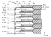
- FIG. 8A is a perspective view showing a cross-sectional view of the main part in a state where the bus bar 131 is joined to the electrode tab 113 of the stacked unit cell 110, and FIG. 8B shows FIG. 8A from the side. It is a side view.
- the left front side is referred to as the entire assembled battery 100 and the “front side” of each component
- the right rear side is referred to as the entire assembled battery 100 and the “rear side” of each component.
- the front side and the back side of the left hand are referred to as the “left and right side sides” of the entire assembled battery 100 and each component.
- the assembled battery 100 includes a stacked body 100S including a battery group 100G in which a plurality of flat cells 110 are stacked in the thickness direction.
- the assembled battery 100 further includes a protective cover 140 that is attached to the front surface side of the stacked body 100S, and a housing 150 that houses the stacked body 100S in a state where each of the single cells 110 is pressurized along the stacking direction of the single cells 110.
- the stacked body 100 ⁇ / b> S includes a battery group 100 ⁇ / b> G and a bus bar unit 130 that is attached to the front side of the battery group 100 ⁇ / b> G and integrally holds a plurality of bus bars 131.
- the protective cover 140 covers and protects the bus bar unit 130.
- the bus bar unit 130 includes a plurality of bus bars 131 and a bus bar holder 132 that integrally attaches the plurality of bus bars 131 in a matrix.
- an anode side terminal 133 is attached to the end on the anode side
- a cathode side terminal 134 is attached to the end on the cathode side.
- the first cell sub-assembly 100M and the second cell sub-assembly 100N have the same configuration except for the refractive direction of the tip 113d of the electrode tab 113 of the unit cell 110.
- the second cell sub-assembly 100N is obtained by reversing the top and bottom of the unit cell 110 included in the first cell sub-assembly 100M.
- the refraction direction of the tip portion 113d of the electrode tab 113 of the second cell sub-assembly 100N is aligned with the lower side of the stacking direction Z so as to be the same as the refraction direction of the tip portion 113d of the electrode tab 113 of the first cell sub-assembly 100M.
- Each unit cell 110 has a pair of spacers 120 (first spacer 121 and second spacer 122) attached thereto.
- the single battery 110 corresponds to, for example, a flat lithium ion secondary battery.
- the unit cell 110 includes a battery body 110H in which the power generation element 111 is sealed with a pair of laminate films 112, and is electrically connected to the power generation element 111 and led out from the battery body 110H. And a thin plate-like electrode tab 113.
- the power generation element 111 is formed by stacking a plurality of positive electrode and negative electrode sandwiched by separators.
- the power generation element 111 is supplied with electric power from the outside and charged, and then supplies electric power while discharging to an external electric device.
- the laminate film 112 is configured to cover both sides of the metal foil with an insulating sheet.
- the pair of laminate films 112 cover the power generation element 111 from both sides along the stacking direction Z and seal the four sides.
- the pair of laminate films 112 lead out the anode-side electrode tab 113 ⁇ / b> A and the cathode-side electrode tab 113 ⁇ / b> K from between the one end 112 a along the short direction Y to the outside.
- the laminate film 112 has a pair of connection pins 121 i of the first spacer 121 in a pair of connection holes 112 e respectively provided at both ends of the one end 112 a along the short direction Y. It is inserted.
- the pair of connection pins 122i of the second spacer 122 are inserted through the pair of connection holes 112e respectively provided at both ends of the other end 112b along the short direction Y.
- the laminate film 112 is formed by bending both end portions 112c and 112d along the longitudinal direction X upward in the stacking direction Z.
- the laminate film 112 may be formed by bending both end portions 112c and 112d along the longitudinal direction X downward in the stacking direction Z.
- the electrode tab 113 includes an anode-side electrode tab 113A and a cathode-side electrode tab 113K.
- Each electrode tab 113 is externally spaced from one end 112a of the pair of laminate films 112. It extends towards.
- the anode-side electrode tab 113A is made of aluminum in accordance with the characteristics of the anode-side component member in the power generation element 111.
- the cathode-side electrode tab 113K is made of copper in accordance with the characteristics of the cathode-side constituent member in the power generation element 111.
- the electrode tab 113 is formed in an L shape from the base end portion 113c adjacent to the battery body 110H to the tip end portion 113d. Specifically, the electrode tab 113 extends along one side in the longitudinal direction X from the base end portion 113c. On the other hand, the tip 113d of the electrode tab 113 is formed by being refracted along the lower side in the stacking direction Z.
- the shape of the tip portion 113d of the electrode tab 113 is not limited to the L shape.
- the tip portion 113 d of the electrode tab 113 is formed in a planar shape so as to face the bus bar 131.
- the electrode tab 113 may be formed in a U-shape by further extending the distal end portion 113d and folding the extended portion along the base end portion 113c toward the battery body 110H.
- the base end portion 113c of the electrode tab 113 may be formed in a wave shape or a curved shape.
- the assembled battery 100 includes three unit cells 110 (first cell sub-assy 100M) electrically connected in parallel and another three unit cells 110 (second cell) connected in parallel.
- Cell subassemblies 100N) are connected in series. Therefore, for each of the three unit cells 110, the top and bottom of the unit cell 110 are switched so that the positions of the anode side electrode tab 113A and the cathode side electrode tab 113K of the unit cell 110 intersect along the stacking direction Z. Yes.
- the anode side electrode tab 113A is arranged on the right side in the figure, and the cathode side electrode tab 113K is arranged on the left side in the figure.
- the cathode side electrode tab 113K is arranged on the right side in the figure, and the anode side electrode tab 113A is arranged on the left side in the figure.
- the tip 113d of the electrode tab 113 of the unit cell 110 is refracted downward along the stacking direction Z. Further, the tip 113d of each electrode tab 113 is disposed on the same surface side of the laminate 100S as shown in FIG.
- a double-sided tape 160 that adheres to a laminated member that is laminated above is attached to the unit cells 110 that are positioned on the upper surfaces of the first cell sub-assembly 100M and the second cell sub-assembly 100N.
- the pair of spacers 120 are disposed between the stacked unit cells 110 as shown in FIGS.
- the first spacer 121 is disposed along one end 112 a of the laminate film 112 from which the electrode tab 113 of the unit cell 110 is projected.
- the second spacer 122 is disposed along the other end 112 b of the laminate film 112.
- the second spacer 122 has a configuration in which the shape of the first spacer 121 is simplified.
- Each cell 110 is stacked with a pair of spacers 120 (first spacer 121 and second spacer 122) and then stacked along the stacking direction Z.
- the pair of spacers 120 (the first spacer 121 and the second spacer 122) are made of reinforced plastics having insulating properties.
- the configuration of the second spacer 122 will be described in comparison with the configuration of the first spacer 121.
- the first spacer 121 is formed in a long rectangular parallelepiped shape along the short direction Y as shown in FIGS.
- the first spacer 121 includes mounting portions 121M and 121N at both ends in the longitudinal direction (short direction Y).
- the first spacer 121 includes a locating hole 121 e along the stacking direction Z for inserting bolts that connect the plurality of assembled batteries 100 connected along the stacking direction Z. Openings to 121M and 121N, respectively.
- the first spacer 121 is laminated on the outer side surface along the short direction Y of the mounting portion 121M and the outer side surface along the short direction Y of the mounting portion 121N.
- a recess 121f formed by cutting out in a concave shape along the direction Z is provided.
- the recess 121f engages with a protrusion 731 provided in the engagement jig 730 in the method for manufacturing the assembled battery 100 described later.
- the recess 121 f includes a first surface 121 s located on the front side, a second surface 121 t provided on the back side, a connecting surface 121 u that connects the first surface 121 s and the second surface 121 t,
- the first spacer 121 has an extended surface 121 v that extends along the stacking direction Z on the front side (the tip side where the electrode tab 113 faces the bus bar 131).
- the first spacer 121 is formed such that a region between the mounting portions 121M and 121N is cut out from the upper side in the stacking direction Z as shown in FIG. 6B and FIG.
- the notched portion includes a first support surface 121g and a second support surface 121h along the longitudinal direction of the first spacer 121 (the short direction Y of the unit cell 110).
- the first support surface 121g is formed higher in the stacking direction Z than the second support surface 121h, and is positioned on the unit cell 110 side.
- the first spacer 121 places and supports one end 112a of the laminate film 112 from which the electrode tab 113 protrudes, by the first support surface 121g.
- the first spacer 121 includes a pair of connecting pins 121i protruding upward from both ends of the first support surface 121g.
- the first spacer 121 abuts the electrode tab 113 from the opposite side of the bus bar 131 and supports the support portion 121j that supports the tip portion 113d of the electrode tab 113 of the unit cell 110 as the second support surface 121h. And provided on the side surface along the stacking direction Z.
- the support portion 121j of the first spacer 121 sandwiches the front end portion 113d of the electrode tab 113 together with the bus bar 131 so that the front end portion 113d and the bus bar 131 are sufficiently in contact with each other.
- the support surface 122k places and supports the other end 112b of the laminate film 112. Similar to the first spacer 121, the second spacer 122 includes a positioning pin 122c, a positioning hole, a locating hole 122e, and a connecting pin 122i.
- the bus bar unit 130 includes a plurality of bus bars 131 integrally.
- the bus bar 131 is made of a metal having conductivity, and electrically connects the tip end portions 113d of the electrode tabs 113 of different unit cells 110.
- the bus bar 131 is formed in a flat plate shape and stands along the stacking direction Z.
- the bus bar 131 includes an anode side bus bar 131A laser welded to the anode side electrode tab 113A of one unit cell 110 and a cathode side laser welded to the cathode side electrode tab 113K of another unit cell 110 adjacent along the stacking direction Z.
- the bus bar 131K is joined and integrally configured.
- the anode-side bus bar 131A and the cathode-side bus bar 131K have the same shape and are formed in an L shape.
- the anode-side bus bar 131A and the cathode-side bus bar 131K are superposed with the top and bottom reversed.
- the bus bar 131 includes a refracted portion 131L at one end along the stacking direction Z of the anode-side bus bar 131A and a refracted portion 131L at one end along the stacking direction Z of the cathode-side bus bar 131K. It is joined and integrated. As shown in FIG.
- the anode-side bus bar 131 ⁇ / b> A and the cathode-side bus bar 131 ⁇ / b> K include a side portion 131 c along the longitudinal direction X from one end in the short-side direction Y.
- the side part 131 c is joined to the bus bar holder 132.
- the bus bar holder 132 is a pair of standing up along the stacking direction Z so as to be positioned on both sides in the longitudinal direction of the first spacer 121 that supports the electrode tab 113 of the unit cell 110.
- Each column portion 132a is provided.
- the pair of support columns 132a are fitted to the side surfaces of the mounting portions 121M and 121N of the first spacer 121.
- the pair of struts 132a are L-shaped when viewed along the stacking direction Z, and are formed in a plate shape extending along the stacking direction Z.
- the bus bar holder 132 is provided with a pair of auxiliary struts 132 b that are erected along the stacking direction Z so as to be located near the center of the first spacer 121 in the longitudinal direction.
- the pair of auxiliary struts 132b are formed in a plate shape extending along the stacking direction Z.
- the bus bar holder 132 may be configured by joining the supporting column part 132a, the auxiliary supporting column part 132b, and the insulating part 132c formed independently from each other, or the supporting column part 132a, the auxiliary supporting column part 132b, and the insulating part 132c are integrally formed. You may form and comprise.
- the anode side terminal 133 is joined to the anode side bus bar 131 ⁇ / b> A located at the upper right in the figure among the bus bars 131 arranged in a matrix.
- the anode side terminal 133 is made of a metal plate having conductivity, and when viewed along the short direction Y, the one end 133b and the other end 133c are aligned along the stacking direction Z with the central portion 133a as a reference. It consists of shapes refracted in different directions.
- the one end 133b is laser-bonded to the anode-side bus bar 131A.
- the other end portion 133c connects an external input / output terminal to a hole 133d (including a screw groove) opened in the center thereof.
- the cathode-side terminal 134 corresponds to the cathode-side end of the battery group 100G formed by alternately stacking the first cell sub-assemblies 100M and the second cell sub-assemblies 100N. As shown in FIGS. 3 and 4, the cathode side terminal 134 is joined to the cathode side bus bar 131 ⁇ / b> K located at the lower left in the figure among the bus bars 131 arranged in a matrix. The cathode side terminal 134 has the same configuration as the anode side terminal 133.
- the protective cover 140 covers the bus bar unit 130 so that the bus bars 131 are short-circuited with each other, or the bus bar 131 is in contact with an external member to be short-circuited or short-circuited. To prevent. Further, the protective cover 140 causes the anode side terminal 133 and the cathode side terminal 134 to face the outside, and charges and discharges the power generation element 111 of each unit cell 110.
- the protective cover 140 is made of plastics having insulating properties.
- the protective cover 140 is formed in a flat plate shape and stands along the stacking direction Z.
- the protective cover 140 has a shape in which the upper end 140b and the lower end 140c of the side surface 140a thereof are refracted along the longitudinal direction X, and is fitted to the bus bar unit 130.
- the side surface 140 a of the protective cover 140 is formed of a rectangular hole that is slightly larger than the anode side terminal 133 at a position corresponding to the anode side terminal 133 provided in the bus bar unit 130.
- a first opening 140d is provided.
- the side surface 140a of the protective cover 140 includes a second opening 140e formed of a rectangular hole slightly larger than the cathode side terminal 134 at a position corresponding to the cathode side terminal 134 provided in the bus bar unit 130. Yes.
- the housing 150 accommodates the battery group 100G in a state where it is pressurized along the stacking direction.
- An appropriate surface pressure is applied to the power generation element 111 by pressing the power generation element 111 of each unit cell 110 provided in the battery group 100G with the upper pressure plate 151 and the lower pressure plate 152.
- the upper pressure plate 151 is disposed above the battery group 100G in the stacking direction Z.
- the upper pressure plate 151 has a pressure surface 151 a protruding downward along the stacking direction Z in the center.
- the power generation element 111 of each unit cell 110 is pressed downward by the pressing surface 151a.
- the upper pressure plate 151 includes a holding portion 151 b that extends along the longitudinal direction X from both sides along the lateral direction Y.
- the holding part 151b covers the placement parts 121M and 121N of the first spacer 121 or the placement parts 122M and 122N of the second spacer 122.
- a locating hole 151c communicating with the positioning hole 121d of the first spacer 121 or the positioning hole 122d of the second spacer 122 along the stacking direction Z is opened.
- the locate hole 151c is inserted with a bolt for connecting the assembled batteries 100 to each other.
- the upper pressure plate 151 is made of a metal plate having a sufficient thickness.
- the upper pressure plate 151 has a notch 151d on the outside of the locate hole 151c in the Y direction. Since the upper pressure plate 151 has the notch 151d as described above, the protrusion 731 of the engagement jig 730 is replaced with the recesses of the plurality of first spacers 121 in the electrode tab positioning step of the battery pack 100 manufacturing method described later. 121f can be engaged.
- the lower pressure plate 152 has the same configuration as the upper pressure plate 151 and reverses the top and bottom of the upper pressure plate 151.
- the lower pressure plate 152 is disposed below along the stacking direction Z of the battery group 100G.
- the lower pressure plate 152 presses the power generation element 111 of each unit cell 110 upward by the pressure surface 151a protruding upward along the stacking direction Z.
- Each side plate 153 is subjected to seam welding or spot welding along the longitudinal direction X with respect to the portion of the upper end 153 a that is in contact with the upper pressure plate 151. Similarly, each side plate 153 is subjected to seam welding or spot welding along the longitudinal direction X with respect to the portion of the lower end 153 b that is in contact with the lower pressure plate 152.
- the pair of side plates 153 covers and protects both sides in the short direction Y of the battery group 100G.
- the manufacturing method of the assembled battery 100 includes a stacking step (FIG. 9) for stacking members constituting the assembled battery 100.
- the method of manufacturing the assembled battery 100 includes an electrode tab positioning step (FIGS. 10 to 13 and FIGS. 16 to 19) for positioning the joining portion of the electrode tab 113 with respect to the bus bar 131 to a predetermined position.
- the electrode tab positioning step includes a spacer alignment step (FIGS. 10 to 13) in which the first spacer 121 is moved in one direction in a state where the unit cell 110 and the first spacer 121 are stacked.
- the electrode tab positioning step includes a contact step (FIGS.
- the method for manufacturing the assembled battery 100 includes a pressurizing step (FIG. 14) for pressurizing the battery group 100G of the assembled battery 100, and a first joining step (FIG. 14) for joining the side plate 153 to the upper pressurizing plate 151 and the lower pressurizing plate 152. 15).
- the method for manufacturing the assembled battery 100 includes a second joining step (FIGS. 20 to 22) in which the bus bar 131 is joined to the electrode tab 113 of the unit cell 110 and the terminal is joined to the bus bar 131.
- the method for manufacturing the assembled battery 100 includes a mounting step (FIG. 23) for attaching the protective cover 140 to the bus bar 131.
- the manufacturing apparatus 700 for the assembled battery 100 in the manufacturing apparatus 700 for the assembled battery 100, the mounting table 710 on which members constituting the assembled battery 100 are placed and the extending surface 121 v of the first spacer 121 are brought into contact with each other.
- the manufacturing apparatus 700 for the assembled battery 100 includes an engagement jig 730 that can be engaged with the recess 121f of the first spacer 121, and a moving unit that moves the engagement jig 730. 740 and a pressurizing jig 750 used in the pressurizing step. Further, as shown in FIGS.
- the manufacturing apparatus 700 for the assembled battery 100 includes a pressing plate 760 used for the first joining process, a contact jig 780 for moving the bus bar 131 toward the battery body 110H, and a laser.
- FIG. 9 is a diagram showing a method for manufacturing the assembled battery 100 according to the present embodiment, and is a perspective view schematically showing a state in which members constituting the assembled battery 100 are sequentially stacked on the mounting table 710. is there.
- the mounting table 710 used in the stacking process is formed in a plate shape and provided along a horizontal plane.
- the mounting table 710 is a locating pin for positioning that aligns the relative positions of the lower pressure plate 152, the first cell sub-assembly 100M, the second cell sub-assembly 100N, and the upper pressure plate 151, which are sequentially stacked, along the longitudinal direction X and the short direction Y. 711.
- Four locate pins 711 stand on the upper surface 710a of the mounting table 710 at a predetermined interval. The distance between the four locate pins 711 corresponds to the distance between the locate holes 152c provided at the four corners of the upper pressure plate 151, for example.
- the members constituting the assembled battery 100 are stacked using a robot arm, a hand lifter, a vacuum suction type collet, or the like.
- the locate pin 711 is configured to provide a predetermined clearance with respect to the locate holes 121e and 122e of the spacer 120, the locate hole 151c of the upper pressure plate 151, and the locate hole 152c of the lower pressure plate 152.
- the lower pressure plate 152 is placed by the robot arm while being lowered along the stacking direction Z in the state where the locating holes 152c provided at the four corners are inserted into the locating pins 711. It is mounted on the upper surface 710 a of the mounting table 710.
- the first cell sub-assembly 100M is arranged along the stacking direction Z in the state where the locating holes 121e and 122e provided in the first spacer 121 and the second spacer 122 of the constituent members are inserted into the locating pins 711.
- the lower pressure plate 152 is laminated while being lowered.
- first cell sub-assemblies 100N and first cell sub-assemblies 100M are alternately stacked by the robot arm.
- a double-sided tape 160 is attached to the upper surface of the first cell sub-assembly 100M and the second cell sub-assembly 100N to be bonded to a laminated member that is laminated above.
- the upper pressure plate 151 is stacked on the first cell sub-assembly 100M by the robot arm while being lowered along the stacking direction Z in a state where the locate holes 151c provided at the four corners are inserted into the locate pins 711.
- the locate pin 711 is configured to provide a predetermined clearance with respect to the locate holes 121e, 122e, 151c, and 152c. For this reason, after the stacking process is completed, the plurality of single cells 110 and the spacers 120 stacked in the stacking direction Z may vary in position on the XY plane.
- the spacer positioning step in the electrode tab positioning step for positioning the electrode tab 113 by eliminating the variation in the position on the XY plane will be described with reference to FIGS.
- FIG. 10 is a perspective view showing a state in which the reference jig 720 is arranged on the mounting table 710 and the convex portion 731 of the engaging jig 730 is engaged with the concave portion 121f of the first spacer 121.
- FIG. FIG. 11 is a top view showing the state of FIG.
- FIG. 12A is a diagram showing a state before the engagement jig 730 is moved in the portion A of FIG. 11, and FIG. 12B is a state before the engagement jig 730 is moved. It is a schematic diagram shown.
- FIG. 13A is a diagram illustrating a state after the engagement jig 730 is moved in the portion A of FIG. 11, and FIG. 13B is a diagram after the engagement jig 730 is moved. It is a schematic diagram which shows a mode.
- the reference jig 720 is fixed and placed on the mounting table 710 as shown in FIG.
- the method for fixing the reference jig 720 to the mounting table 710 is not particularly limited.
- the reference jig 720 has a reference surface 721 on which the extending surface 121v of the first spacer 121 abuts when the engagement jig 730 moves.
- the engaging jig 730 is disposed adjacent to the reference jig 720 along the X direction.
- the engagement jig 730 is moved in the XY directions by the moving means 740.
- the moving means 740 moves the first spacer 121 to the X direction negative side in a state where the unit cell 110 and the first spacer 121 are stacked, thereby joining the electrode tab 113 to the bus bar 131 in the moving direction of the first spacer 121.
- the part is positioned at a predetermined position.
- the moving means 740 For example, an air cylinder, an electric cylinder, etc. can be used.
- the engaging jig 730 has the convex portion 731 that can be engaged with the concave portion 121 f of the first spacer 121.
- the surface 732 adjacent to the reference jig 720 of the engagement jig 730 is in a state where the extending surface 121v of the first spacer 121 is in contact with the reference surface 721 of the reference jig 720, as shown in FIG. In FIG. 5, the reference jig 720 is arranged with a predetermined clearance.
- the convex portion 731 of the engaging jig 730 is engaged with the concave portion 121 f of the first spacer 121 by the moving means 740. Specifically, the engaging jig 730 is moved leftward in the Y direction in FIG. 12A by the moving means 740 (see the arrow in FIG. 12A). At this time, as shown in FIG. 12B, the first spacer 121 has a variation in position in the X direction along the stacking direction Z.
- the engagement jig 730 is moved leftward in the X direction by the moving means 740 as shown by the arrow in FIG.
- the range in which the first spacer 121 moves is equal to or less than the clearance between the locate hole 121e and the locate pin 711. .
- rough positioning is performed in advance by the locate hole 121e and the locate pin 711, and precise positioning is performed by the engagement jig 730. For this reason, the time spent for an electrode tab positioning process can be reduced.
- the first spacer 121 is moved to the reference jig 720 while the convex portion 731 of the engagement jig 730 is in contact with the first surface 121s of the concave portion 121f. And move toward the reference plane 721.
- the extending surface 121 v of the first spacer 121 abuts on the reference surface 721 of the reference jig 720.
- the extending surface 121v of the first spacer 121 along the stacking direction becomes the same plane in the YZ plane as shown in FIG. 13B.
- the joint portion of the electrode tab 113 to the bus bar 131 can be aligned along the stacking direction Z.
- FIG. 14 is a perspective view schematically showing a state in which the constituent members of the assembled battery 100 are pressed from above, following FIG. 13.
- the pressurizing jig 750 used in the pressurizing process includes a pressurizing unit 751 formed in a plate shape and provided along a horizontal plane, and a support unit 752 formed in a columnar shape and joined upright on the upper surface of the pressurizing unit 751 It is equipped with.
- the support portion 752 connects an electric stage and a hydraulic cylinder that are driven along the stacking direction Z.
- the pressurizing unit 751 moves downward and upward along the stacking direction Z via the support unit 752.
- the pressurizing unit 751 pressurizes the laminated member in contact.
- the pressurizing unit 751 of the pressurizing jig 750 is driven in the stacking direction Z while being in contact with the upper pressurizing plate 151 by driving the electric stage connected to the support unit 752. Descent along the bottom.
- the upper pressure plate 151 pressed along the lower side and the lower pressure plate 152 mounted on the mounting table 710 are pressed while sandwiching the battery group 100G.
- An appropriate surface pressure is applied to the power generation element 111 of each unit cell 110 provided in the battery group 100G.
- the pressurizing process is continued until the next first joining process is completed.
- a first joining step for joining the side plate 153 to the upper pressure plate 151 and the lower pressure plate 152 will be described with reference to FIG.
- FIG. 15 is a perspective view schematically showing a state in which the side plate 153 is laser-welded to the upper pressure plate 151 and the lower pressure plate 152 following FIG.
- the pressing plate 760 used in the first joining step presses the side plate 153 against the upper pressure plate 151 and the lower pressure plate 152, respectively, and brings the side plate 153 into close contact with the upper pressure plate 151 and the lower pressure plate 152, respectively.
- the push plate 760 is made of metal and is formed in a long plate shape.
- the pressing plate 760 has a linear slit 762 in the main body 761 along the longitudinal direction.
- the pressing plate 760 is erected in the lateral direction along the stacking direction Z.
- the pressing plate 760 allows the laser beam L1 for welding to pass through the slit 762 while pressing the side plate 153 by the main body 761.
- the laser oscillator 770 is a light source that joins the side plate 153 to the upper pressure plate 151 and the lower pressure plate 152.
- the laser oscillator 770 is composed of, for example, a YAG (yttrium, aluminum, garnet) laser.
- the laser beam L1 derived from the laser oscillator 770 irradiates the upper end 153a and the lower end 153b of the side plate 153 in a state where the optical path is adjusted by, for example, an optical fiber or a mirror and condensed by a condenser lens.
- the laser beam L1 derived from the laser oscillator 770 may be branched by a half mirror and irradiated to the upper end 153a and the lower end 153b of the side plate 153 at the same time.
- the laser oscillator 770 scans the laser beam L1 horizontally through the slit 762 of the pressing plate 760 with respect to the upper end 153 a of the side plate 153 pressed by the pressing plate 760. Then, the side plate 153 and the upper pressure plate 151 are joined by seam welding at a plurality of locations. Similarly, the laser oscillator 770 scans the side plate 153 and the lower pressure plate 152 horizontally with the laser beam L1 through the slit 762 of the push plate 760 with respect to the lower end 153b of the side plate 153 pressed by the push plate 760. Join by seam welding at multiple locations.
- the abutting jig 780 used in the abutting step moves the bus bar 131 toward the battery main body 110 ⁇ / b> H, and causes the bus bar 131 to abut the tip portion 113 d of the electrode tab 113 against the support portion 121 j of the first spacer 121. Further, as shown in FIG. 20, the contact jig 780 pushes the bus bar 131 so as to surround the joint portion of the electrode tab 113 to the bus bar 131, and moves the bus bar 131 to the battery body 110H side.
- the contact jig 780 includes a main body portion 781, a first opening 782 that opens linearly along the Y direction, and a linear shape along the Z direction. It has the 2nd opening part 783 which opens, and the press surface 784 which presses the bus bar 131.
- the first opening 782 is formed to allow the laser beam L1 and the refracting part 131L of the bus bar 131 to pass through (see FIG. 21). Moreover, the 2nd opening part 783 is formed in order to pass the auxiliary support
- the pressing surface 784 is formed so as to surround a joint portion of the electrode tab 113 with respect to the bus bar 131. For this reason, the bus bar 131 can be suitably moved to the battery main body 110H side with the full length along the Y direction of the junction part with respect to the bus bar 131 of the electrode tab 113.
- the pressing surface 784 is formed so as to be able to press all of the bus bars 131 attached to the bus bar holder 132. Therefore, the bus bar 131 attached to the bus bar holder 132 can be uniformly moved to the battery body 110H side, so that work is facilitated.
- the mounting table 710 rotates 90 ° counterclockwise in the drawing so that the electrode tab 113 of the battery group 100 ⁇ / b> G and the laser oscillator 770 face each other. . Then, the bus bar holder 132 holding each bus bar 131 integrally is brought into contact with the corresponding electrode tab 113 of the battery group 100G by a robot arm (not shown).
- the position in the X direction of the tip portion 113d of each electrode tab 113 may be relatively shifted in the Z direction.
- the third and sixth electrode tabs 113 from the top are in contact with the support portions 121j of the corresponding first spacers 121 at the tip portions 113d3 and 113d6.
- the first, second, fourth, and fifth electrode tabs 113 correspond to the tip portions 113d1, 113d2, 113d4, and 113d5.
- the first spacers 121 are spaced apart from the support portions 121j.
- the above-described relationship between the tip portion 113d of the electrode tab 113 and the support portion 121j of the first spacer 121 is an example, and other combinations are possible. Since the first spacer 121 is aligned in the above-described spacer alignment step, the position in the X direction coincides in the Z direction as shown in FIG.
- the bus bar 131 After the bus bar holder 132 is brought into contact with the electrode tab 113, as shown in FIGS. 18 and 19, the bus bar 131 is moved to the battery main body 110H side (rightward in the X direction in FIG. 19) by the contact jig 780. As a result, the bus bar 131 causes the tip end portion 113 d of each electrode tab 113 to abut the corresponding support portion 121 j of each corresponding first spacer 121. Among the six electrode tabs 113 shown in FIG. 19, the first, second, fourth, and fifth electrode tabs 113 have a slightly different base end 113c when moving to the battery body 110H side. Bend.
- the contact portions 113 d of all the electrode tabs 113 come into contact with the corresponding support portions 121 j of the first spacers 121, so that the electrode tabs 113 are joined to the bus bar 131. Can be positioned at a predetermined position.
- FIG. 20 is a perspective view schematically showing a state in which the bus bar 131 of the bus bar unit 130 is laser-welded to the electrode tab 113 of the unit cell 110 following FIG. 18 and FIG. 19.
- FIG. 21 is a side view showing in cross section the main part in a state where the bus bar 131 is laser-bonded to the electrode tab 113 of the stacked unit cell 110.
- FIG. 22 is a perspective view schematically showing a state in which the anode side terminal 133 and the cathode side terminal 134 are laser-welded to the anode side bus bar 131A and the cathode side bus bar 131K following FIG. 20 and FIG.
- the laser oscillator 770 irradiates the bus bar 131 with the laser light L1 through the first opening 782, and the bus bar 131 and the tip end portions of the electrode tab 113 113d is joined by seam welding or spot welding.
- the tip portion 113 d of the electrode tab 113 is sandwiched between the support portion 121 j of the first spacer 121 and the bus bar 131 in the region excluding the joined portion of the electrode tab 113. .
- laser bonding can be performed with the gap between the bus bar 131 and the tip end portion 113d of the electrode tab 113 being minimized, and the bonding quality is improved. Further, as shown in FIG.
- the tip portion 113d of the electrode tab 113 is positioned so that the position in the X direction extends in the Z direction. That is, since the position where the electrode tab 113 is bonded to the bus bar 131 is positioned at a predetermined position, the bonding quality is improved. Thereafter, the contact jig 780 is removed, and as shown in FIG. 22, the anode-side bus bar 131A corresponding to the terminal end of the anode side among the bus bars 131 in which the anode-side terminals 133 are arranged in a matrix (upper right in FIG. 4) ). Similarly, the cathode side terminal 134 is joined to the cathode side bus bar 131K (lower left in FIG. 4) corresponding to the end of the cathode side among the bus bars 131 arranged in a matrix.
- the protective cover 140 is attached to the bus bar unit 130 while the upper end 140b and the lower end 140c of the protective cover 140 are fitted to the bus bar unit 130 using a robot arm.
- the upper end 140b and the lower end 140c of the protective cover 140 may be joined to the bus bar unit 130 with an adhesive.
- the protective cover 140 has the anode side terminal 133 exposed to the outside from the first opening 140d and the cathode side terminal 134 exposed to the outside from the second opening 140e.
- the bus bar unit 130 is covered with the protective cover 140 to prevent the bus bars 131 from being short-circuited or from being short-circuited or leaked due to the bus bar 131 contacting an external member.
- the assembled battery 100 that has been manufactured is removed from the mounting table 710 and carried out to an inspection process for inspecting battery performance and the like.
- the manufacturing method of the assembled battery 100 described with reference to FIGS. 9 to 23 includes an automatic machine that controls the entire process with a controller, a semi-automatic machine that handles a part of the process, or a manual that handles the entire process. It may be embodied by any form of the machine.
- the bus bar 131 is moved to the battery body 110H side, and the front end portion 113d of the electrode tab 113 is moved to the support portion 121j of the first spacer 121 by the bus bar 131. Make contact. Further, in the joining step, the joining portion of the electrode tab 113 in a state where the tip portion 113d of the electrode tab 113 is sandwiched between the support portion 121j of the first spacer 121 and the bus bar 131 in the region excluding the joining portion of the electrode tab 113.
- the bus bar 131 is laser-joined.
- the front end portions 113d of all the electrode tabs 113 come into contact with the support portions 121j of the corresponding first spacers 121, so that the positions where the electrode tabs 113 are joined to the bus bar 131 at a predetermined position are more suitable. Can be done. In addition, laser joining can be performed with as little gap as possible between the bus bar 131 and the tip 113d of the electrode tab 113, and the joining quality is improved.
- the electrode tab 113 is positioned by bringing the first spacer 121 into contact with the reference surface 721 serving as a reference. According to this manufacturing method, since the electrode tab 113 can be positioned by bringing the first spacer 121 into contact with the reference surface 721, the electrode tab 113 can be easily positioned. Therefore, the manufacturing method becomes easy.
- the first spacer 121 including the locate hole 121e along the stacking direction Z is disposed on the mounting table 710 including the locate pin 711 extending in the stacking direction. Laminate to penetrate.
- the range in which the first spacer 121 moves is equal to or less than the clearance between the locate hole 121e and the locate pin 711. According to this manufacturing method, rough positioning is performed in advance by the locate hole 121e and the locate pin 711, and precise positioning is performed by the engagement jig 730. For this reason, the time spent for an electrode tab positioning process can be reduced.
- the bus bar 131 is joined to the electrode tab 113 in a state where the joining portion of the electrode tab 113 with respect to the bus bar 131 is positioned. For this reason, the distance from the arrangement position of the laser oscillator 770 to the electrode tab 113 can be aligned with high accuracy along the stacking direction Z. Therefore, the electrode tab 113 and the bus bar 131 can be suitably joined at the time of laser welding.
- the tip 113 d of the electrode tab 113 is refracted along the stacking direction Z of the unit cells 110.
- the moving means 740 moves the first spacer 121 in the surface direction of the unit cell 110 and away from the unit cell 110 (X direction negative side). According to this manufacturing apparatus 700, since the first spacer 121 is moved away from the unit cell 110, the electrode tab 113 can be easily positioned.
- the contact jig 780 pushes the bus bar 131 so as to surround the joining portion, and moves the bus bar 131 to the battery body 110H side. For this reason, the bus bar 131 can be suitably moved to the battery main body 110H side with the full length along the Y direction of the junction part with respect to the bus bar 131 of the electrode tab 113.
- FIG. 1
- the manufacturing apparatus 700 further includes a reference jig 720 including a reference surface 721 for positioning each electrode tab 113 by contacting each first spacer 121.
- a reference jig 720 including a reference surface 721 for positioning each electrode tab 113 by contacting each first spacer 121.
- the manufacturing apparatus 700 further includes an engagement jig 730 including a convex portion 731 that can be engaged with the concave portion 121f provided in the spacer 120. According to this manufacturing apparatus 700, each extending surface 121v can be easily made into the same plane.
- the manufacturing apparatus 700 further includes a mounting table 710 including a locating pin 711 that is inserted into a locating hole 121e provided in the first spacer 121 along the stacking direction Z.
- the range in which the spacer 120 moves is equal to or less than the clearance between the locate hole 121e and the locate pin 711. According to this manufacturing apparatus 700, rough positioning is performed in advance by the locate hole 121e and the locate pin 711, and precise positioning is performed by the engagement jig 730. For this reason, the time spent for an electrode tab positioning process can be reduced.
- the first spacer 121 is moved by moving the engagement jig 730 in a state where the projection 731 of the engagement jig 730 is engaged with the recess 121f of the first spacer 121. It was.
- the present invention is not limited to this, and the engaging jig may be provided with a recess, the first spacer may be provided with a protrusion, and they may be engaged with each other.
- the first spacer 121 is moved by the engagement jig 730 and the moving means 740.
- the first spacer 121 may be held and moved by the hand robot.
- the contact jig 780 moves the bus bar 131 toward the battery body 110 ⁇ / b> H, and the bus bar 131 is in a state where the tip portion 113 d of the electrode tab 113 is in contact with the support portion 121 j of the first spacer 121. 131 was joined to the tip 113 d of the electrode tab 113.
- the contact jig 780 moves the bus bar 131 toward the battery main body 110 ⁇ / b> H, and the tip end portion 113 d of the electrode tab 113 contacts the support portion 121 j of the first spacer 121.
- the contact jig 780 is removed and the bus bar 131 is joined to the tip portion 113d of the electrode tab 113. May be.
Abstract
Description
100G 電池群、
110 単電池、
110H 電池本体、
111 発電要素、
113 電極タブ、
113d 電極タブの先端部、
120 一対のスペーサ、
121 第1スペーサ、
121e ロケート孔、
121f 凹部、
121v 延在面、
122 第2スペーサ、
131 バスバ、
700 組電池の製造装置、
710 載置台、
711 ロケートピン、
720 基準治具、
721 基準面、
730 係合治具、
731 凸部、
740 移動手段、
770 レーザ発振器(接合手段)、
780 当接治具。
Claims (14)
- 発電要素を含み扁平に形成した電池本体および前記電池本体から導出した電極タブを備える単電池と前記電極タブを支持するスペーサとを積層してなる電池群と、前記電極タブに接合されて複数の前記電極タブを電気的に接続するバスバと、を有する組電池の製造方法であって、
前記バスバを前記電極タブに接合する前に、前記単電池および前記スペーサを積層した状態で前記スペーサを一方向に移動させることによって、前記スペーサの移動方向で、前記電極タブの前記バスバに対する接合部位の所定の位置への位置決めを行う電極タブ位置決め工程と、
前記電極タブの前記接合部位を前記所定の位置に位置決めした状態で、前記電極タブに前記バスバを接合する接合工程と、を有する組電池の製造方法。 - 前記電極タブの先端部は、前記単電池の積層方向に沿って屈折し、
前記電極タブ位置決め工程において、前記スペーサを前記単電池の面方向であって前記単電池から離れる向きに、前記スペーサを移動させる請求項1に記載の組電池の製造方法。 - 前記電極タブ位置決め工程において、
前記スペーサを移動させた後に、前記バスバを前記電池本体側へ移動させて、前記バスバによって前記電極タブの前記先端部を前記スペーサに当接させ、
前記接合工程において、
前記電極タブの前記接合部位を除く領域において前記スペーサと前記バスバとの間に前記電極タブを挟み込んだ状態で、前記電極タブの前記接合部位に前記バスバをレーザ接合する請求項2に記載の組電池の製造方法。 - 前記電極タブ位置決め工程において、
前記接合部位を囲うように前記バスバを押して、前記バスバを前記電池本体側へ移動させる請求項3に記載の組電池の製造方法。 - 前記スペーサを移動させる際に、
前記スペーサを、基準となる基準面に当接させることによって前記電極タブの位置決めを行う請求項1~4のいずれか1項に記載の組電池の製造方法。 - 前記スペーサに設けられる凹部に、係合治具に設けられる凸部を係合した状態で、前記係合治具を移動させることによって前記スペーサを移動する請求項1~5のいずれか1項に記載の組電池の製造方法。
- 前記スペーサを移動させる前に、
前記単電池の積層方向に沿うロケート孔を備える前記スペーサを、前記積層方向に伸びるロケートピンを備える載置台に対して、前記ロケートピンを前記ロケート孔に挿通させるように積層し、
前記スペーサの移動する範囲は、前記ロケート孔と前記ロケートピンとの間のクリアランス以下である請求項1~6のいずれか1項に記載の組電池の製造方法。 - 発電要素を含み扁平に形成した電池本体および前記電池本体から導出した電極タブを備える単電池と前記電極タブを支持するスペーサとを積層してなる電池群と、前記電極タブに接合されて複数の前記電極タブを電気的に接続するバスバと、を有する組電池の製造装置であって、
前記単電池および前記スペーサを積層した状態で前記スペーサを一方向に移動させることによって、前記スペーサの移動方向で、前記電極タブの前記バスバに対する接合部位の所定の位置への位置決めを行う移動手段と、
前記電極タブの前記接合部位を所定の位置に位置決めした状態で、前記電極タブに前記バスバを接合する接合手段と、を有する組電池の製造装置。 - 前記電極タブの先端部は、前記単電池の積層方向に沿って屈折し、
前記移動手段は、前記スペーサを前記単電池の面方向であって前記単電池から離れる向きに、前記スペーサを移動させる請求項8に記載の組電池の製造装置。 - 前記バスバを前記電池本体側へ移動させて、前記バスバによって前記電極タブの前記先端部を前記スペーサに当接させる当接治具をさらに有する請求項9に記載の組電池の製造装置。
- 前記当接治具は、前記接合部位を囲うように前記バスバを押して、前記バスバを前記電池本体側へ移動させる請求項10に記載の組電池の製造装置。
- 各々の前記スペーサが当接されることによって各々の前記電極タブの位置決めを行う基準面を備える基準治具をさらに有する請求項8~11のいずれか1項に記載の組電池の製造装置。
- 前記スペーサに設けられる凹部に係合可能な凸部を備える係合治具をさらに有する請求項8~12のいずれか1項に記載の組電池の製造装置。
- 前記スペーサに前記単電池の積層方向に沿って設けられるロケート孔に挿通するロケートピンを備える載置台をさらに有し、
前記スペーサの移動する範囲は、前記ロケート孔と前記ロケートピンとの間のクリアランス以下である請求項8~13のいずれか1項に記載の組電池の製造装置。
Priority Applications (5)
| Application Number | Priority Date | Filing Date | Title |
|---|---|---|---|
| US15/765,507 US10553840B2 (en) | 2015-10-22 | 2016-10-13 | Manufacturing method and manufacturing device for battery pack |
| CN201680061667.XA CN108140792B (zh) | 2015-10-22 | 2016-10-13 | 组电池的制造方法及制造装置 |
| JP2017546521A JP6617154B2 (ja) | 2015-10-22 | 2016-10-13 | 組電池の製造方法および製造装置 |
| KR1020187011870A KR101943284B1 (ko) | 2015-10-22 | 2016-10-13 | 조전지의 제조 방법 및 제조 장치 |
| EP16857360.8A EP3367471A4 (en) | 2015-10-22 | 2016-10-13 | Production method and production device for battery pack |
Applications Claiming Priority (2)
| Application Number | Priority Date | Filing Date | Title |
|---|---|---|---|
| JPPCT/JP2015/079902 | 2015-10-22 | ||
| PCT/JP2015/079902 WO2017068707A1 (ja) | 2015-10-22 | 2015-10-22 | 組電池の製造方法および製造装置 |
Publications (1)
| Publication Number | Publication Date |
|---|---|
| WO2017069045A1 true WO2017069045A1 (ja) | 2017-04-27 |
Family
ID=58556797
Family Applications (2)
| Application Number | Title | Priority Date | Filing Date |
|---|---|---|---|
| PCT/JP2015/079902 WO2017068707A1 (ja) | 2015-10-22 | 2015-10-22 | 組電池の製造方法および製造装置 |
| PCT/JP2016/080427 WO2017069045A1 (ja) | 2015-10-22 | 2016-10-13 | 組電池の製造方法および製造装置 |
Family Applications Before (1)
| Application Number | Title | Priority Date | Filing Date |
|---|---|---|---|
| PCT/JP2015/079902 WO2017068707A1 (ja) | 2015-10-22 | 2015-10-22 | 組電池の製造方法および製造装置 |
Country Status (6)
| Country | Link |
|---|---|
| US (1) | US10553840B2 (ja) |
| EP (1) | EP3367471A4 (ja) |
| JP (1) | JP6617154B2 (ja) |
| KR (1) | KR101943284B1 (ja) |
| CN (1) | CN108140792B (ja) |
| WO (2) | WO2017068707A1 (ja) |
Cited By (5)
| Publication number | Priority date | Publication date | Assignee | Title |
|---|---|---|---|---|
| JP2018006215A (ja) * | 2016-07-05 | 2018-01-11 | 日産自動車株式会社 | 溶接装置および溶接方法 |
| JP2019034452A (ja) * | 2017-08-10 | 2019-03-07 | 日産自動車株式会社 | 積層部材の積層方法および積層部材の積層装置 |
| KR20200123705A (ko) * | 2019-04-22 | 2020-10-30 | (주)휴민텍 | 배터리 셀 스택장치 |
| EP3654432A4 (en) * | 2017-07-11 | 2021-03-24 | Wuhan Yifi Laser Equipment Co., Ltd. | STACKING DEVICE FOR FLEXIBLE PACKAGING BATTERIES |
| JP2021536115A (ja) * | 2018-12-21 | 2021-12-23 | エルジー・ケム・リミテッド | 電極リードをバスバーに密着させる加圧ジグ装置及びそれを含むバッテリーモジュール製造システム |
Families Citing this family (10)
| Publication number | Priority date | Publication date | Assignee | Title |
|---|---|---|---|---|
| KR102101429B1 (ko) * | 2016-05-18 | 2020-04-16 | 주식회사 엘지화학 | 리드 용접 장치, 이러한 리드 용접 장치를 통해 제조되는 배터리 모듈 및 이러한 배터리 모듈을 포함하는 배터리 팩 |
| JP6504468B2 (ja) * | 2016-09-16 | 2019-04-24 | トヨタ自動車株式会社 | 着脱補助装置 |
| EP3579304A4 (en) * | 2017-01-31 | 2020-02-19 | Envision AESC Japan Ltd. | METHOD FOR PRODUCING A BATTERY PACK AND PRODUCTION DEVICE |
| JP6856520B2 (ja) * | 2017-12-05 | 2021-04-07 | 本田技研工業株式会社 | バッテリモジュール |
| CN107887564A (zh) * | 2017-12-08 | 2018-04-06 | 华霆(合肥)动力技术有限公司 | 电池模组及电池模组系统 |
| CN112204810B (zh) * | 2018-08-13 | 2023-02-17 | 日本汽车能源株式会社 | 电池组件 |
| KR20200097510A (ko) * | 2019-02-08 | 2020-08-19 | 에스케이이노베이션 주식회사 | 배터리 모듈 및 이의 제조방법 |
| KR102043114B1 (ko) * | 2019-04-25 | 2019-11-27 | 백영진 | 2차전지셀 전극리드탭의 용접 가이드 장치 |
| KR102303444B1 (ko) * | 2019-11-29 | 2021-09-23 | (주)휴민텍 | 배터리 셀 팔레트 장치 |
| JP2022068756A (ja) * | 2020-10-22 | 2022-05-10 | 株式会社エンビジョンAescジャパン | バッテリモジュール、バッテリ装置およびバッテリモジュールの製造方法 |
Citations (9)
| Publication number | Priority date | Publication date | Assignee | Title |
|---|---|---|---|---|
| JP2007042578A (ja) * | 2005-07-04 | 2007-02-15 | Nissan Motor Co Ltd | 電池モジュールおよび電池モジュールの組み立て方法 |
| JP2007172893A (ja) * | 2005-12-19 | 2007-07-05 | Nissan Motor Co Ltd | 電池モジュール |
| JP2009231267A (ja) * | 2008-02-29 | 2009-10-08 | Nissan Motor Co Ltd | 電池モジュールおよび電池モジュールの製造方法 |
| WO2013146097A1 (ja) * | 2012-03-29 | 2013-10-03 | 日産自動車株式会社 | バスバー取り付け装置およびバスバー取り付け方法 |
| WO2014073443A1 (ja) * | 2012-11-09 | 2014-05-15 | 日産自動車株式会社 | 組電池および組電池の製造方法 |
| JP2014110219A (ja) * | 2012-12-04 | 2014-06-12 | Nissan Motor Co Ltd | 組電池および組電池の製造方法 |
| JP2014135162A (ja) * | 2013-01-09 | 2014-07-24 | Auto Network Gijutsu Kenkyusho:Kk | 蓄電モジュール |
| WO2014171559A1 (ko) * | 2013-04-15 | 2014-10-23 | 주식회사 엘지화학 | 신규한 구조의 전지모듈 및 이를 포함하는 전지팩 |
| WO2014185732A1 (ko) * | 2013-05-16 | 2014-11-20 | 타이코에이엠피(유) | 배터리 패키지 |
Family Cites Families (12)
| Publication number | Priority date | Publication date | Assignee | Title |
|---|---|---|---|---|
| JP4513451B2 (ja) | 2004-07-27 | 2010-07-28 | 日産自動車株式会社 | 組電池 |
| WO2007121445A2 (en) | 2006-04-18 | 2007-10-25 | Securaplane Technologies, Inc. | Battery busing scheme |
| KR101136800B1 (ko) | 2008-02-29 | 2012-04-19 | 주식회사 엘지화학 | 전지모듈의 제조방법 및 중대형 전지팩 |
| US8815429B2 (en) | 2009-01-12 | 2014-08-26 | A123 Systems Llc | Busbar supports and methods of their use for battery systems |
| JP5423067B2 (ja) * | 2009-03-11 | 2014-02-19 | 日産自動車株式会社 | 電池モジュールおよびその製造方法 |
| WO2010113455A1 (ja) * | 2009-03-31 | 2010-10-07 | 三洋電機株式会社 | 電池モジュール、バッテリシステムおよび電動車両 |
| US20140356685A1 (en) * | 2011-09-30 | 2014-12-04 | Sanyo Electric Co., Ltd. | Assembled cell |
| JP5916500B2 (ja) | 2012-04-27 | 2016-05-11 | オートモーティブエナジーサプライ株式会社 | 組電池 |
| KR20130131658A (ko) * | 2012-05-24 | 2013-12-04 | 에스케이이노베이션 주식회사 | 이차 전지용 레이저 용접 지그 및 그 용접 방법 |
| CN202839792U (zh) * | 2012-09-25 | 2013-03-27 | 万向电动汽车有限公司 | 一种层叠式电芯的电芯单体承力结构 |
| KR20140056836A (ko) * | 2012-11-01 | 2014-05-12 | 주식회사 엘지화학 | 전지모듈 및 이를 포함하는 전지팩 |
| CN103151550B (zh) * | 2013-03-16 | 2015-04-08 | 大力电工襄阳股份有限公司 | 用于组装层叠式堆体的装置 |
-
2015
- 2015-10-22 WO PCT/JP2015/079902 patent/WO2017068707A1/ja active Application Filing
-
2016
- 2016-10-13 US US15/765,507 patent/US10553840B2/en active Active
- 2016-10-13 JP JP2017546521A patent/JP6617154B2/ja active Active
- 2016-10-13 WO PCT/JP2016/080427 patent/WO2017069045A1/ja active Application Filing
- 2016-10-13 CN CN201680061667.XA patent/CN108140792B/zh active Active
- 2016-10-13 EP EP16857360.8A patent/EP3367471A4/en active Pending
- 2016-10-13 KR KR1020187011870A patent/KR101943284B1/ko active IP Right Grant
Patent Citations (10)
| Publication number | Priority date | Publication date | Assignee | Title |
|---|---|---|---|---|
| JP2007042578A (ja) * | 2005-07-04 | 2007-02-15 | Nissan Motor Co Ltd | 電池モジュールおよび電池モジュールの組み立て方法 |
| JP2007172893A (ja) * | 2005-12-19 | 2007-07-05 | Nissan Motor Co Ltd | 電池モジュール |
| JP2009231267A (ja) * | 2008-02-29 | 2009-10-08 | Nissan Motor Co Ltd | 電池モジュールおよび電池モジュールの製造方法 |
| WO2013146097A1 (ja) * | 2012-03-29 | 2013-10-03 | 日産自動車株式会社 | バスバー取り付け装置およびバスバー取り付け方法 |
| JP2013206772A (ja) * | 2012-03-29 | 2013-10-07 | Nissan Motor Co Ltd | バスバー取り付け装置およびバスバー取り付け方法 |
| WO2014073443A1 (ja) * | 2012-11-09 | 2014-05-15 | 日産自動車株式会社 | 組電池および組電池の製造方法 |
| JP2014110219A (ja) * | 2012-12-04 | 2014-06-12 | Nissan Motor Co Ltd | 組電池および組電池の製造方法 |
| JP2014135162A (ja) * | 2013-01-09 | 2014-07-24 | Auto Network Gijutsu Kenkyusho:Kk | 蓄電モジュール |
| WO2014171559A1 (ko) * | 2013-04-15 | 2014-10-23 | 주식회사 엘지화학 | 신규한 구조의 전지모듈 및 이를 포함하는 전지팩 |
| WO2014185732A1 (ko) * | 2013-05-16 | 2014-11-20 | 타이코에이엠피(유) | 배터리 패키지 |
Non-Patent Citations (1)
| Title |
|---|
| See also references of EP3367471A4 * |
Cited By (7)
| Publication number | Priority date | Publication date | Assignee | Title |
|---|---|---|---|---|
| JP2018006215A (ja) * | 2016-07-05 | 2018-01-11 | 日産自動車株式会社 | 溶接装置および溶接方法 |
| EP3654432A4 (en) * | 2017-07-11 | 2021-03-24 | Wuhan Yifi Laser Equipment Co., Ltd. | STACKING DEVICE FOR FLEXIBLE PACKAGING BATTERIES |
| JP2019034452A (ja) * | 2017-08-10 | 2019-03-07 | 日産自動車株式会社 | 積層部材の積層方法および積層部材の積層装置 |
| JP2021536115A (ja) * | 2018-12-21 | 2021-12-23 | エルジー・ケム・リミテッド | 電極リードをバスバーに密着させる加圧ジグ装置及びそれを含むバッテリーモジュール製造システム |
| JP7147052B2 (ja) | 2018-12-21 | 2022-10-04 | エルジー エナジー ソリューション リミテッド | 電極リードをバスバーに密着させる加圧ジグ装置及びそれを含むバッテリーモジュール製造システム |
| KR20200123705A (ko) * | 2019-04-22 | 2020-10-30 | (주)휴민텍 | 배터리 셀 스택장치 |
| KR102187276B1 (ko) * | 2019-04-22 | 2020-12-04 | (주)휴민텍 | 배터리 셀 스택장치 |
Also Published As
| Publication number | Publication date |
|---|---|
| CN108140792A (zh) | 2018-06-08 |
| US10553840B2 (en) | 2020-02-04 |
| JPWO2017069045A1 (ja) | 2018-08-02 |
| KR101943284B1 (ko) | 2019-01-28 |
| CN108140792B (zh) | 2020-12-18 |
| JP6617154B2 (ja) | 2019-12-11 |
| US20190074490A1 (en) | 2019-03-07 |
| EP3367471A1 (en) | 2018-08-29 |
| KR20180049166A (ko) | 2018-05-10 |
| WO2017068707A1 (ja) | 2017-04-27 |
| EP3367471A4 (en) | 2018-12-19 |
Similar Documents
| Publication | Publication Date | Title |
|---|---|---|
| JP6617154B2 (ja) | 組電池の製造方法および製造装置 | |
| JP6633643B2 (ja) | 組電池および組電池の製造方法 | |
| WO2017068706A1 (ja) | 組電池および組電池の製造方法 | |
| JP6782246B2 (ja) | 組電池の組み立て方法および組電池 | |
| JP6519662B2 (ja) | 組電池 | |
| JP6737905B2 (ja) | 組電池、組電池に用いられるバスバホルダおよび組電池の製造方法 | |
| JP6667255B2 (ja) | 組電池および組電池の製造方法 | |
| JP6690920B2 (ja) | 組電池および組電池用のバスバカバー並びに組電池の製造方法 | |
| WO2018142476A1 (ja) | 組電池の製造方法および製造装置 | |
| JP6667254B2 (ja) | 組電池 | |
| JP6777387B2 (ja) | 組電池 | |
| JP2017084469A (ja) | 組電池および組電池用のスペーサ | |
| JP2018181773A (ja) | 組電池、組電池に用いられるバスバホルダおよび組電池の製造方法 |
Legal Events
| Date | Code | Title | Description |
|---|---|---|---|
| 121 | Ep: the epo has been informed by wipo that ep was designated in this application |
Ref document number: 16857360 Country of ref document: EP Kind code of ref document: A1 |
|
| ENP | Entry into the national phase |
Ref document number: 2017546521 Country of ref document: JP Kind code of ref document: A |
|
| NENP | Non-entry into the national phase |
Ref country code: DE |
|
| ENP | Entry into the national phase |
Ref document number: 20187011870 Country of ref document: KR Kind code of ref document: A |
|
| WWE | Wipo information: entry into national phase |
Ref document number: 2016857360 Country of ref document: EP |