WO2017065151A1 - 超伝導磁石装置とその異常時の電流低下抑制方法 - Google Patents
超伝導磁石装置とその異常時の電流低下抑制方法 Download PDFInfo
- Publication number
- WO2017065151A1 WO2017065151A1 PCT/JP2016/080182 JP2016080182W WO2017065151A1 WO 2017065151 A1 WO2017065151 A1 WO 2017065151A1 JP 2016080182 W JP2016080182 W JP 2016080182W WO 2017065151 A1 WO2017065151 A1 WO 2017065151A1
- Authority
- WO
- WIPO (PCT)
- Prior art keywords
- current
- short
- superconducting coil
- superconducting
- circuit
- Prior art date
- Legal status (The legal status is an assumption and is not a legal conclusion. Google has not performed a legal analysis and makes no representation as to the accuracy of the status listed.)
- Ceased
Links
Images


Classifications
-
- H—ELECTRICITY
- H02—GENERATION; CONVERSION OR DISTRIBUTION OF ELECTRIC POWER
- H02H—EMERGENCY PROTECTIVE CIRCUIT ARRANGEMENTS
- H02H7/00—Emergency protective circuit arrangements specially adapted for specific types of electric machines or apparatus or for sectionalised protection of cable or line systems, and effecting automatic switching in the event of an undesired change from normal working conditions
- H02H7/001—Emergency protective circuit arrangements specially adapted for specific types of electric machines or apparatus or for sectionalised protection of cable or line systems, and effecting automatic switching in the event of an undesired change from normal working conditions for superconducting apparatus, e.g. coils, lines, machines
-
- H—ELECTRICITY
- H01—ELECTRIC ELEMENTS
- H01F—MAGNETS; INDUCTANCES; TRANSFORMERS; SELECTION OF MATERIALS FOR THEIR MAGNETIC PROPERTIES
- H01F6/00—Superconducting magnets; Superconducting coils
- H01F6/02—Quenching; Protection arrangements during quenching
-
- H—ELECTRICITY
- H01—ELECTRIC ELEMENTS
- H01F—MAGNETS; INDUCTANCES; TRANSFORMERS; SELECTION OF MATERIALS FOR THEIR MAGNETIC PROPERTIES
- H01F6/00—Superconducting magnets; Superconducting coils
- H01F6/06—Coils, e.g. winding, insulating, terminating or casing arrangements therefor
-
- H—ELECTRICITY
- H02—GENERATION; CONVERSION OR DISTRIBUTION OF ELECTRIC POWER
- H02H—EMERGENCY PROTECTIVE CIRCUIT ARRANGEMENTS
- H02H3/00—Emergency protective circuit arrangements for automatic disconnection directly responsive to an undesired change from normal electric working condition with or without subsequent reconnection ; integrated protection
- H02H3/12—Emergency protective circuit arrangements for automatic disconnection directly responsive to an undesired change from normal electric working condition with or without subsequent reconnection ; integrated protection responsive to underload or no-load
-
- Y—GENERAL TAGGING OF NEW TECHNOLOGICAL DEVELOPMENTS; GENERAL TAGGING OF CROSS-SECTIONAL TECHNOLOGIES SPANNING OVER SEVERAL SECTIONS OF THE IPC; TECHNICAL SUBJECTS COVERED BY FORMER USPC CROSS-REFERENCE ART COLLECTIONS [XRACs] AND DIGESTS
- Y02—TECHNOLOGIES OR APPLICATIONS FOR MITIGATION OR ADAPTATION AGAINST CLIMATE CHANGE
- Y02E—REDUCTION OF GREENHOUSE GAS [GHG] EMISSIONS, RELATED TO ENERGY GENERATION, TRANSMISSION OR DISTRIBUTION
- Y02E40/00—Technologies for an efficient electrical power generation, transmission or distribution
- Y02E40/60—Superconducting electric elements or equipment; Power systems integrating superconducting elements or equipment
Definitions
- the present invention relates to a superconducting magnet device comprising a superconducting coil formed of a high-temperature superconducting wire and a superconducting coil for generating a magnetic field by supplying a current to the superconducting coil.
- the present invention also relates to a method for suppressing a decrease in current when the superconducting magnet device is abnormal.
- the superconducting magnet device can generate a strong magnetic field by including a superconducting coil capable of flowing a large current.
- a superconducting magnet device can be used as a magnet for NMR (nuclear magnetic resonance) or a magnet for MRI (magnetic resonance imaging).
- the superconducting magnet device can also be used in other applications (for example, a linear motor car).
- superconductivity may be expressed as superconductivity, it is expressed as superconductivity in the present application.
- a superconducting magnet device has been put into practical use, for example, as an NMR magnet, using a superconducting coil formed of a low-temperature superconducting wire.
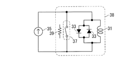
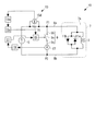
- the superconducting magnet device includes a superconducting coil 31 formed of a low-temperature superconducting wire, a diode 33 connected in parallel to the superconducting coil 31, a power supply 35 for supplying current to the superconducting coil 31, and a permanent current switch. 37 and a heater 39 for heating.
- the permanent current switch 37 is formed of a low temperature superconducting wire. Since this low-temperature superconducting wire 37 functions as a switch as will be described later, in FIG. 1A to FIG. 1C, it is represented by a switch symbol. Further, a closed circuit (a thick line circuit in FIG.
- this closed circuit is referred to as a superconducting closed circuit.
- the superconducting magnet apparatus of FIGS. 1A to 1C can generate a magnetic field in a permanent current mode in which current does not decay by the following procedure.
- the superconducting coil 31, the diode 33, and the permanent current switch 37 are placed in liquid helium in the cooling vessel 38. Thereby, the above-mentioned superconducting closed circuit is cooled below the transition temperature.
- the transition temperature is a temperature at which the transition from the normal state to the superconducting state (hereinafter the same). Therefore, the superconducting closed circuit is in a superconducting state with zero electrical resistance.
- the permanent current switch 37 is heated by the heater 39 to a temperature higher than the above transition temperature.
- the permanent current switch 37 (superconducting wire) transitions to the normal conducting state, and the superconducting closed circuit is disconnected. In other words, the permanent current switch 37 is turned off (the state shown in FIG. 1A).
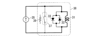
- the current flowing through the permanent current switch 37 increases.
- the value of the current flowing from the permanent current switch 37 to the superconducting coil 31 becomes the above-described rated current value.
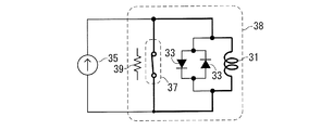
- This current circulates in the superconducting closed circuit described above without being attenuated. That is, the current flows through the thick line in this figure as shown in FIG. 1C.
- the superconducting magnet device is in a permanent current mode in which the superconducting coil 31 generates a magnetic field without a power source.
- a superconducting magnet device that generates a magnetic field in the permanent current mode as described above is described in, for example, Patent Document 1 below.
- the superconducting magnet device of FIGS. 1A to 1C uses a low-temperature superconducting wire, it is desired to realize a superconducting magnet device using a high-temperature superconducting wire.
- the high-temperature superconducting wire mainly has the following two advantages.
- the transition temperature of the high-temperature superconducting wire is, for example, not less than the boiling point (77K) of liquid nitrogen and higher than the transition temperature of the low-temperature superconducting wire.
- a large current can be passed through the high-temperature superconducting wire even in a high magnetic field.
- a superconducting coil formed of a high-temperature superconducting wire can be brought into a superconducting state by using, for example, liquid nitrogen or a small refrigerator.
- the superconducting coil of the high-temperature superconducting wire can obtain a strong magnetic field by flowing a large current through the superconducting coil of the high-temperature superconducting wire even in a high magnetic field (even when the magnetic field generated from the surroundings is high).
- a superconducting magnet device having a superconducting coil of a high-temperature superconducting wire can generate a magnetic field having the same strength with a smaller configuration than when a low-temperature superconducting wire is used.
- the superconducting magnet device includes a superconducting coil 41 formed of a high-temperature superconducting wire, a diode 43 connected in parallel to the superconducting coil 41, and a power supply 45 for supplying current to the superconducting coil 41.
- the circuit portion including the superconducting coil 41 and the diode 43 is heated at a high temperature by, for example, a refrigerant (that is, liquid nitrogen, liquid hydrogen, liquid argon, liquid helium, or other cryogenic refrigerant) in the cooling container 47 or a small refrigerator. It is cooled below the transition temperature of the superconducting wire.
- a refrigerant that is, liquid nitrogen, liquid hydrogen, liquid argon, liquid helium, or other cryogenic refrigerant
- the current flowing in the closed circuit including the diode 43 and the superconducting coil 41 prevents the current in the superconducting coil 41 from becoming zero instantaneously.
- the current rapidly decreases to zero even if not instantaneously.
- at least one (for example, all) of the following problems (A), (B), and (C) occurs.
- a large inductance for example, 10H to 2000H, preferably 50H to 1000H
- the superconducting portion is made into a multifilament.
- high-temperature superconducting wires including wires other than tape, are difficult to multifilament or cannot be multifilamented as low-temperature superconducting wires. If it is not multifilament or if its amount is small, hysteresis loss occurs due to the shielding current in a variable magnetic field.
- the high-temperature superconducting coil 41 has a larger hysteresis loss than the low-temperature superconducting coil, and heat is generated due to a larger hysteresis loss in the high-temperature superconducting coil 41 during magnet excitation and demagnetization (increase or decrease in magnet current). appear.
- the temperature of a part of the superconducting coil 41 increases locally at the place due to heat generated by the hysteresis loss, and in some cases exceeds the critical temperature. Since a current is applied, the critical temperature at this time is significantly smaller than the critical temperature when no magnetic field is applied and no current is applied.
- the rate at which the current is reduced by the protection circuit using the diode 43 is very high, and the local thermal runaway may occur due to the hysteresis loss unique to the high-temperature superconducting coil 41 if only the protection circuit using the diode 43 is used.
- the inventor of the present application has found.
- the inventor of the present application has found that the superconducting magnet device using a superconducting coil formed of a high-temperature superconducting wire has a power supply exceeding an abnormal state or for other reasons (for example, power supply maintenance). It has been found that it is desirable to suppress a decrease in the current flowing through the superconducting coil when it is disconnected from the conducting coil. That is, when the power source is disconnected from the superconducting coil, if the decrease in the value of the current flowing through the superconducting coil can be suppressed, the problems (A), (B), and (C) can be solved. Found by the person.
- a superconducting magnet device Installed a superconducting magnet device, (B) generating a magnetic field in the superconducting coil by flowing a current from the power source through the superconducting coil in a superconducting state; (C) When an abnormality of the superconducting magnet device is detected after generating the magnetic field according to (B), or when the power source and the superconducting coil are separated from each other, the protection device Provided is a method for suppressing a current drop in a superconducting magnet device that forms a short-circuit path.
- the superconducting coil can continue to generate a magnetic field for a while (for example, 6 hours to several days).
- the value of the current flowing through the above-described closed circuit when the restoration is completed Is still big enough. Therefore, it is not necessary to gradually increase the value of the current flowing through the superconducting coil from zero when the current supply from the power source is resumed after the restoration is completed, so that the current value is gradually increased to the target value. Takes less time to complete. For example, when the above-described abnormal state occurs at midnight, the current value can be increased to the target value in a short time even if the recovery is completed in the morning of the day.
- the current supply from the power source to the superconducting coil is started, and when it is detected that the magnitude of the current flowing through the short-circuit path is less than the set value, the short-circuit path is canceled.
- the current value of the superconducting coil can be prevented from fluctuating due to the current in the short circuit path.
- a superconducting coil formed of a high-temperature superconducting wire;
- a superconducting magnet device comprising a protective device capable of forming a short-circuit path that short-circuits both ends of the superconducting coil.
- a superconducting magnet device is provided. That is, the superconducting magnet device of the present invention may not include a power supply as a constituent feature.
- a short circuit path can be formed by the protective device.
- a closed circuit including a superconducting coil and a short circuit path is formed.
- the current flowing through the superconducting coil circulates in this closed circuit. Since the electric resistance of the closed circuit is very small, it is possible to suppress a decrease in current circulating in the closed circuit.
- such a superconducting magnet device can suppress the frequency of use of the power supply by utilizing the protection function of the protection device that suppresses a decrease in current in the event of an abnormality, for example, according to the usage mode (for example, Modification Example 8 described later). Is possible. In this case, even when the power source is not connected to the superconducting coil, the decrease in current can be suppressed or reduced.
- the above-described superconducting magnet device can be configured as follows, for example.
- the superconducting magnet device of (i) or (ii) above is When detecting that the superconducting magnet device is in an abnormal state, a detection device that outputs a short circuit signal; And an actuating device that activates the protection device so that the protection device forms the short-circuit path when the short-circuit signal is output.
- the protection device includes a switch, and the short circuit path is formed by closing the switch.
- the power source is a constant current source that supplies a constant current to the superconducting coil, and the constant current is Flowing from one end of the superconducting coil to the other end,
- the above-described superconducting magnet device includes a reverse diode connected in antiparallel to the superconducting coil.
- the protective device forms a short circuit path, so that the current path of the superconducting coil is switched from the reverse diode path to the short circuit path. Therefore, the amount of heat generated by the reverse diode can be kept very small.
- the detection device comprises: A supply current detector for detecting the magnitude of the current supplied to the superconducting coil by the power source; A supply current comparison unit for determining whether the magnitude of the current detected by the supply current detection unit does not satisfy the setting condition; And a short-circuit signal output unit that outputs the short-circuit signal when the abnormal state occurs when the supply current comparison unit determines that the magnitude of the current does not satisfy the set condition.
- the short circuit signal output unit outputs a short circuit signal, thereby forming a short circuit path.
- an abnormal state for example, a power failure
- the detection device comprises: A voltage detection unit for detecting a magnitude of a voltage between two points of a current path connecting the power source and the superconducting coil; A voltage comparison unit for determining whether the magnitude of the voltage detected by the voltage detection unit no longer satisfies the setting condition; And a short-circuit signal output unit that outputs the short-circuit signal when the abnormal state occurs when the voltage comparison unit determines that the magnitude of the voltage no longer satisfies the set condition.
- the detection device includes: A power supply abnormality detection unit for detecting the power supply abnormality; A short-circuit signal output unit that outputs the short-circuit signal when the abnormal state occurs when the power-supply abnormality detection unit detects the abnormality of the power source.
- the short circuit signal output unit outputs a short circuit signal. Thereby, the above-mentioned short circuit path is formed.
- the superconducting magnet device is A short-circuit current detector that detects the magnitude of the current flowing through the short-circuit path formed by the protection device;
- a short-circuit current comparator for determining whether the magnitude of the current detected by the short-circuit current detector is equal to or less than a set value;
- a release signal output unit that outputs a short-circuit release signal to the operating device is provided, and the operating device receives the short-circuit release signal or the short-circuit release signal And the short-circuit release command are received, the short-circuit path by the protection device is released.
- the superconducting magnet device is A plurality of magnetic field generation devices having the superconducting coil and the protection device,
- the power source is shared by the plurality of magnetic field generation devices,
- a coil state detection unit that is provided in each magnetic field generation device and detects the magnitude of the current flowing through the superconducting coil or the magnitude of the magnetic field generated by the superconducting coil;
- a current supply switch provided in each magnetic field generation device and operated between a closed position where current is supplied from the power source to the magnetic field generation device and an open position where the magnetic field generation device is disconnected from the power source;
- the current supply switch of the magnetic field generation device is closed.
- a control device to be operated.
- one power source is provided for a plurality of superconducting coils, and when the current of the superconducting coil falls below the reference value, the current is supplied from the power source to the superconducting coil.
- the frequency of use and the number of uses can be reduced.
- the protection function of the protection device that suppresses a decrease in current in the event of an abnormality can be utilized (for example, Modification Example 7 described later). Further, even when the power source is not connected to the superconducting coil, the decrease in current can be suppressed or reduced.
- FIG. 1A It is a circuit diagram of a superconducting magnet device using a low-temperature superconducting wire.
- a path through which a current flows is shown in the circuit diagram of FIG. 1A.
- 1B shows another path through which a current flows in the circuit diagram of FIG. 1A.
- the structural example of a freezing container is shown.
- the other structural example of a freezing container is shown.
- the other structural example of a freezing container is shown.
- 3 is a flowchart illustrating a method for suppressing current decrease according to an embodiment of the present invention.
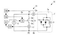
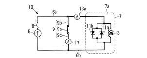
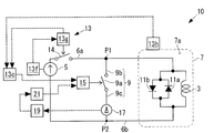
- FIG. 3A is a circuit diagram showing the superconducting magnet device 10 according to the embodiment of the present invention.
- the superconducting magnet device 10 may be a device that generates a magnetic field (for example, a static magnetic field) as a magnet for NMR or a magnet for MRI.
- the superconducting magnet device 10 may be a device that generates a magnetic field (for example, a static magnetic field) in another device (for example, a linear motor car or a particle accelerator).
- the superconducting magnet device 10 includes a superconducting coil 3, a power source 5, a cooling container 7, a protection device 9, a reverse diode 11 a, a forward diode 11 b, a detection device 13, and an operating device 15.
- a current detection unit 17 and a short-circuit current comparison unit 19 are provided.
- the superconducting coil 3 is provided for generating a magnetic field.
- Superconducting coil 3 is formed of a high-temperature superconducting wire.
- This high temperature superconducting wire is, for example, a tape-shaped wire.
- the aspect ratio (aspect ratio) of the cross section of the tape-shaped high-temperature superconducting wire (that is, the tape-shaped superconducting coil 3) is, for example, 5 to 10 or more.
- the “high-temperature superconducting wire” is a wire made of a superconductor material having a critical temperature Tc (transition temperature) of about 25 K or more in a non-magnetic field, and is an oxidation containing copper.
- Wires made of superconductor materials such as physical superconductors and iron-based superconductors are all high-temperature superconducting wires.
- a wire made of yttrium-based superconductor and bismuth-based superconductor is a high-temperature superconducting wire, and the one represented by the chemical formula YBa 2 Cu 3 O 7- ⁇ or the element Y in the formula is replaced with a rare earth element.
- a wire made of n O 4 + 2n + ⁇ is a high-temperature superconducting wire.
- high-temperature superconducting wires are those in which oxide nanoparticles such as zirconium and cisprosium are deposited on the wire to improve the critical current characteristics, or in which some are replaced with other elements.
- Wires in metallic superconductors consist of superconducting transition temperature as MgB 2 exceeds 25K is high-temperature superconducting wire.
- the transition temperature of the high temperature superconducting wire is higher than the transition temperature of the low temperature superconducting wire.
- the transition temperature of the high-temperature superconducting wire may be, for example, a value within a range of 25K or more and 153K or less (for example, a value of boiling point 77K or more of liquid nitrogen).
- the superconducting coil 3 may be formed by such a high-temperature superconducting wire.
- a superconducting coil formed of a high-temperature superconducting wire means a coil at least partially (partially or entirely) made of a high-temperature superconducting wire. To do.
- the power supply 5 generates a magnetic field in the superconducting coil 3 by supplying a current to the superconducting coil 3.
- the power source 5 is a constant current source that supplies a constant current to the superconducting coil 3.
- the value of the current that the power source 5 supplies to the superconducting coil 3 is, for example, in the range of 10 A or more and 10000 A or less, preferably 50 A or more and 2000 A or less.
- the positive electrode of the power source 5 and one end of the superconducting coil 3 are connected by a first current path 6a formed of a conductive material.
- the negative electrode of the power supply 5 and the other end of the superconducting coil 3 are connected by a second current path 6b formed of a conductive material.
- the power source 5 may be manufactured and sold separately from the superconducting magnet device 10 excluding the power source 5, and may be connected to the superconducting coil 3 when the superconducting magnet device 10 is installed.
- the cooling vessel 7 has an internal space 7a that is cooled below the transition temperature of the high-temperature superconducting wire forming the superconducting coil 3.
- Superconducting coil 3 is arranged in this internal space 7a.
- the cooling container 7 has the structure of FIG. 3B, FIG. 3C, or FIG. 3D, for example.
- the cooling container 7 has an inner container 7b and an outer container 7c as a double shell structure.
- the inner container 7b has the above-described internal space 7a, and a liquid refrigerant (that is, liquid nitrogen, liquid hydrogen, liquid argon, liquid helium, or other cryogenic refrigerant) is stored in the internal space 7a.
- a liquid refrigerant that is, liquid nitrogen, liquid hydrogen, liquid argon, liquid helium, or other cryogenic refrigerant
- Superconducting coil 3 is arranged in this refrigerant.
- a vacuum layer 7d that is a vacuum is formed between the inner container 7b and the outer container 7c.
- liquid refrigerant is poured into the internal space 7a regularly (for example, once every three months), but no problem occurs in the cooling container 7 even if a power failure occurs.
- the cooling container 7 has the same configuration as that of FIG. 3B, but a refrigerator 7e is attached to the cooling container 7.
- the refrigerator 7e recondenses the refrigerant in the internal space 7a.
- the refrigerator 7e since there is the refrigerator 7e, it is not necessary to periodically add a liquid refrigerant to the internal space 7a.
- the refrigerant in the internal space 7a runs out. (For example, within 7 days)
- the liquid refrigerant is added to the internal space 7a or power is supplied to the refrigerator 7e to restart the operation of the refrigerator 7e.
- a refrigerator 7 f is attached to the cooling container 7.
- the refrigerator 7f and the superconducting coil 3 are thermally connected by a heat conductor (metal plate or knitted wire) 7g.
- the cooling container 7 may be manufactured and sold separately from the superconducting magnet device 10 excluding the cooling container 7 and used with such a superconducting magnet device 10.
- the protective device 9 can form a short-circuit path that short-circuits both ends of the superconducting coil 3.
- the short circuit of the short circuit path may mean that the current decrease rate dI / dt is smaller than that in the case of the reverse diode 11a.
- the amount of heat generated by the electrical resistance of the short-circuit path that is, the amount of decrease in current due to this electrical resistance
- the reverse diode 11a It is smaller than the amount of heat generated at (ie, the amount of decrease in current due to this heat generation).
- the protection device 9 includes a switch 9a.
- One end of the switch 9 a is connected to one end of the superconducting coil 3, and the other end of the switch 9 a is connected to the other end of the superconducting coil 3.
- the protection device 9 includes a first conductive path 9b and a second conductive path 9c.
- the first conductive path 9b connects one end of the switch 9a and the intermediate point P1 of the first current path 6a
- the second conductive path 9c connects the other end of the switch 9a and the second current path 6b. Is connected to the middle point P2.
- Such a protective device 9 is provided outside the cooling container 7 in FIG. 3A, but may be provided in the internal space 7 a of the cooling container 7 together with the short-circuit current detection unit 17, and the element thereof is the cooling container. 7 may be distributed outside and inside.
- the protection device 9 is provided outside the power supply 5; however, the protection device 9 may be provided inside the power supply 5 (outside the cooling container 7), and the element of the protection device 9 is the power supply 5 It may be distributed outside and inside.
- the reverse diode 11 a is connected to the superconducting coil 3 in antiparallel. That is, the cathode of the reverse diode 11a is connected to one end of the superconducting coil 3 (positive electrode of the constant current source 5), and the anode of the reverse diode 11a is connected to the other end of the superconducting coil 3 (constant current source 5). Negative electrode).
- the anode of the forward diode 11b is connected to one end of the superconducting coil 3 (positive electrode of the constant current source 5), and the cathode of the forward diode 11b is connected to the other end of the superconducting coil 3 (constant current source). 5 negative electrode). Note that the forward diode 11b may be omitted.
- Detecting device 13 outputs a short-circuit signal to operating device 15 when detecting an abnormal state of superconducting magnet device 10 (for example, a state in which current supply from power supply 5 to superconducting coil 3 is abnormal).
- an abnormal state for example, a state in which current supply from power supply 5 to superconducting coil 3 is abnormal.
- this abnormal state is simply referred to as an abnormal state.
- such a detection device 13 is provided outside the cooling container 7, but may be provided in the internal space 7 a of the cooling container 7, and elements thereof may be provided outside and inside the cooling container 7. It may be provided in a distributed manner.
- the detection device 13 includes a supply current detection unit 13a, a supply current comparison unit 13b, and a short circuit signal output unit 13c.
- the supply current detection unit 13 a detects the magnitude of the current that the power source 5 supplies to the superconducting coil 3.
- the supply current detection unit 13a may be an ammeter.
- the ammeter 13a is provided in the first current path 6a in FIG. 3A, but may be provided in the second current path 6b.
- the supply current detection unit 13a only needs to detect the magnitude of the current supplied from the power supply 5 to the superconducting coil 3, and various configurations and arrangements of the supply current detection unit 13a can be employed.
- the supply current detection unit 13a measures the voltage at both ends of the superconducting coil 3, or the voltage at both ends of a resistor having a known electrical resistance value provided in the first current path 6a or the second current path 6b.
- the magnitude of the current supplied from the power source 5 to the superconducting coil 3 may be detected from the measured value.
- the supply current detection unit 13a may calculate the value (strength) of the magnetic field generated by the current flowing through the superconducting coil 3 or other part (for example, the first current path 6a or the second current path 6b), for example, DCCT or Hall
- the magnitude of the current supplied from the power source 5 to the superconducting coil 3 may be detected on the basis of the measured magnetic field value measured using an element or NMR phenomenon.
- the supply current comparison unit 13b determines whether the magnitude of the current detected by the supply current detection unit 13a does not satisfy the set condition.
- This setting condition is a condition that the magnitude of the current detected by the supply current detector 13a is larger than the threshold value, or a condition that the magnitude of this current is within the setting range.
- This threshold value may be zero, a value close to zero (for example, a value within a range of 0.1 A to 10 A), or a current detected by the supply current detection unit 13a during normal operation. May be a predetermined ratio (for example, an arbitrary ratio of 10% or less).
- the set range may be a range of the magnitude of the current detected by the supply current detection unit 13a at a normal time or a range close to this range.
- the short-circuit signal output unit 13c is determined by the supply current comparison unit 13b that the detection current value by the supply current detection unit 13a does not satisfy the above-described setting condition (that is, the detection current value is equal to or less than a threshold value, Alternatively, when the detected current value is smaller or larger than the set range), a short circuit signal is output to the actuator 15 as an abnormal condition has occurred.
- the actuating device 15 actuates the protective device 9 so that the protective device 9 forms a short circuit path by receiving the short circuit signal.
- the operation of the protection device 9 is an operation of closing the switch 9a. That is, the actuator 15 forms a short circuit path by closing the switch 9a.
- the actuating device 15 closes the switch 9a mechanically (by mechanical power) or magnetically (by electromagnetic force). Actuator 15 may be constituted so that switch 9a may be closed using gravity.
- the short circuit current detection unit 17 detects the magnitude of the current flowing through the short circuit path formed by the protection device 9.
- the short-circuit current detector 17 only needs to be able to detect the magnitude of the current flowing through the short-circuit path, and various configurations and arrangements of the short-circuit current detector 17 can be employed.
- the short-circuit current detection unit 17 may be provided in the second conductive path 9c as illustrated in FIG. 3A or may be provided in the first conductive path 9b.
- the short-circuit current detector 17 measures the voltage between the first conductive path 9b and the second conductive path 9c, and the measured value, the first conductive path 9b, and the second conductive path You may detect the magnitude
- the short-circuit current detection unit 17 determines the magnitude of the current flowing through the short-circuit path from the difference in current value at two locations other than the protective device 9 (the first conductive path 9b and the second conductive path 9c). May be detected. These two locations may be, for example, one location on the first current path 6a upstream from the midpoint P1 and one location on the first current path 6a downstream from the midpoint P1.
- the short circuit current detection part 17 may detect an electric current by the same principle as the supply current detection part 13a.
- the short-circuit current detection unit 17 measures the value of the magnetic field generated by the current flowing in the superconducting coil 3 or another location (for example, the short-circuit path), and based on this measurement value, the current flowing in the short-circuit path The size may be detected.
- the short-circuit current comparison unit 19 determines whether or not the magnitude of the current detected by the short-circuit current detection unit 17 is equal to or less than a set value (zero or a value close to zero) after recovery from the abnormal state.
- This set value is, for example, a value within a range of 0A or more and 1A or less. Preferably, this set value is a value in the range of 0 A or more and 0.2 A or less.
- the release signal output unit 21 outputs a short-circuit release signal to the actuator 15 when the result of determination by the short-circuit current comparison unit 19 is affirmative.
- the actuating device 15 releases the short-circuit path by the protection device 9 when receiving the short-circuit release signal or when receiving both the short-circuit release signal and the short-circuit release command.
- the short-circuit release command is output from the command output unit (not shown) to the actuator 15 after recovery from the abnormal state.
- This command output unit responds, for example, in response to resuming current supply from the power supply 5 to the superconducting coil 3, or in response to a person operating an appropriate operation unit (for example, a button) at the time of resumption.
- the short-circuit release command is output to the actuator 15.
- FIG. 4 is a flowchart showing a method for suppressing current decrease when the superconducting magnet device 10 described above is abnormal.
- FIG. 5A to FIG. 6B are explanatory diagrams of this current drop suppression method.
- a path through which a current flows is indicated by a bold line portion.
- 5A to 6B, illustration of the supply current comparison unit 13b, the short circuit signal output unit 13c, and the like is omitted.
- step S1 the superconducting magnet device 10 described above is installed. This state is shown in FIG. 5A. In FIG. 5A, no current has yet flowed.
- step S2 magnetic field generation by the superconducting magnet device 10 is started as follows.
- step S1 as described above, the superconducting coil 3 in the cooling container 7 is cooled, and the temperature of the internal space 7a of the cooling container 7 is made equal to or lower than the transition temperature of the high-temperature superconducting wire forming the superconducting coil 3. To do. Thereby, superconducting coil 3 will be in a superconducting state.
- step S2 with the switch 9a opened, for example, by closing the switch 8 (see FIGS. 5A to 5C), a current is supplied from the power source 5 to the superconducting coil 3 in the superconducting state. Thus, a magnetic field is generated in the superconducting coil 3.
- the inductance of the superconducting coil 3 (for example, a value in the range of 10H to 2000H, preferably a value in the range of 50H to 1000H) is large, a long time (half day) is set so that the superconducting coil 3 does not generate heat.
- a long time (half day) is set so that the superconducting coil 3 does not generate heat.
- the value of the current flowing through the superconducting coil 3 is changed from zero to the rated current value of the target value (preferably a value within a range of 50 A or more and 2000 A or less). Raise to. This state is shown in FIG. 5B. In FIG.
- the switch 8 is provided on the positive electrode side of the power supply 5. However, the switch 8 may be provided on the negative electrode side of the power supply 5 or on both the positive electrode side and the negative electrode side.
- step S2 the current of the rated current value flows through the superconducting coil 3 in the superconducting state, whereby the superconducting coil 3 generates a magnetic field. Thereafter, in this state, the process proceeds to step S3.
- step S3 when the superconducting coil 3 is generating a magnetic field, the detection device 13 determines whether or not the current supply from the power source 5 to the superconducting coil 3 is abnormal (abnormal state). When detecting the abnormal state, the detection device 13 proceeds to step S4. Otherwise, the determination in step S3 is repeated.
- an abnormal condition for example, there is a failure of the power supply 5.
- the switch 8 shown in FIGS. 5A to 6B is automatically opened, so that the power supply 5 is electrically disconnected from the superconducting coil 3.
- the state of FIG. 5B is shifted to the state of FIG. 5C.
- the current of the superconducting coil 3 flows through a closed circuit including the superconducting coil 3 and the reverse diode 11a (that is, a thick line circuit in this figure).
- the current value detected by the supply current detection unit 13a is significantly smaller than the above-described rated current value and does not satisfy the above-described setting condition. Therefore, this abnormal state is detected by the detection device 13.
- abnormal states include power outages and voltage drops.
- the power supply 5 cannot supply current to the superconducting coil 3.
- the state of FIG. 5B shifts to a state equivalent to FIG. 5C, and this abnormal state is detected by the detection device 13.
- the detection device 13 or the actuator 15 may be operated by an auxiliary power source, or the device that automatically switches the switch 9a to the closed state when the power source is lost. May be used.
- step S4 the detection device 13 outputs a short circuit signal to the operation device 15.
- the actuator 15 forms the short circuit path which short-circuits the both ends of the superconducting coil 3 by operating the protection device 9.
- FIG. 6A a closed circuit including the superconducting coil 3 and the protective device 9 (switch 9a) (that is, a thick line circuit in this figure) flows.
- the electric resistance value of the closed circuit is zero or greater than zero and 75 m ⁇ or less, and preferably zero or greater than zero and 30 m ⁇ or less.
- the resistance of this closed circuit is a value very close to zero. It may be.
- a low temperature superconducting wire for example, the internal space 7a of the cooling container 7 is cooled to a temperature lower than the transition temperature of the low temperature superconducting wire by, for example, liquid helium in step S2.
- the entire closed circuit is preferably arranged in the internal space 7a.
- the current decay rate when the protective device 9 is activated is preferably 1 ⁇ 2 or less of the current decay rate when the reverse diode 11a is activated (state of FIG. 5C). Is preferably 1/5 or less.
- the voltage generated between both ends of the protective device 9 is 0.75 V or less, preferably 0.3 V or less. desirable.
- step S3 the determination in the above-described step S3 is repeatedly performed. If an abnormal state is detected, step S4 described above is performed. Also in this case, after step S4, the process proceeds to step S5.
- step S5 a person performs recovery work such as repair or replacement of the power source 5. As a result, the abnormal state is resolved, and the process proceeds to step S6.
- step S6 the current supply from the normal power source 5 to the superconducting coil 3 is resumed. That is, for example, a current is supplied to the superconducting coil 3 from the repaired power supply 5 or a new power supply 5 in place of the failed power supply 5.
- step S6 may be performed when the person who performed step S5 pushes the button which operates the power supply 5.
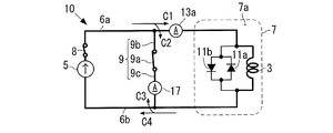
- FIG. 6B the value of the current supplied from the power source 5 to the superconducting coil 3 is gradually increased. This state is shown in FIG. 6B. In FIG. 6B, the current flows through a closed circuit including the superconducting coil 3 and the constant current source 5 (that is, a thick line circuit in this figure). As shown in FIG.
- the current from the constant current source 5 is divided into a current C1 flowing to the superconducting coil 3 and a current C2 flowing to the switch 9a, and the current C1 flowing through the superconducting coil 3 flows to the switch 9a. It is divided into a flowing current C3 and a current C4 flowing to the constant current source 5. Therefore, the current C2 and the current C3 cancel each other.
- the current (C3-C2) flowing through the switch 9a gradually decreases, and when the current C2 and the current C3 become the same size, the current flowing through the switch 9a becomes zero. Become.
- step S7 the short-circuit current comparison unit 19 detects the magnitude of the current flowing through the short-circuit path (switch 9a), and the short-circuit current comparison unit 19 determines whether or not the detected value is equal to or less than the above set value. .
- This set value is zero or a value close to zero (for example, a value greater than 0A and less than or equal to 5A). If the result of the determination in step S7 is affirmative, the process proceeds to step S8, and if not, the determination in step S7 is repeated.
- step S ⁇ b> 8 the release signal output unit 21 outputs the release signal to the operation device 15, so that the operation device 15 releases the short circuit path.
- the operating device 15 opens the switch 9a. This returns to the state of FIG. 5B.
- step S8 the current supplied from the constant current source 5 to the superconducting coil 3 is increased until the value of the current flowing through the superconducting coil 3 reaches the above-described rated current value. As a result, the process returns to step S3 while the current of the rated current value is flowing through the superconducting coil 3 in the superconducting state, and the processes in steps S3 to S8 described above are repeated.
- the superconducting coil 3 can continue to generate a magnetic field (not zero) for a while (for example, 6 hours to several days).
- the current flowing through the closed circuit is still not present when the restoration is completed. Big enough. Therefore, it is not necessary to restart the current supply from the power supply 5 after the restoration is completed and to increase the value of the current flowing through the superconducting coil 3 from zero, so that the current value is gradually increased to the target value. Takes less time. For example, even if the above abnormal condition occurs at midnight, even if recovery work is started in the morning and the recovery is completed in the morning of the day, the current value is gradually increased to the target value after recovery. This time is shortened.
- step S7 when it is detected in step S7 described above that the magnitude of the current flowing through the short circuit path is equal to or less than the set value, the actuator 15 releases the short circuit path. Thereby, when it returns to the original state, it can suppress that the electric current value of the superconducting coil 3 is fluctuate
- exciting the superconducting coil 3 that cannot perform the permanent current mode with the power supply means that the power supply 5 is left connected to the superconducting coil 3 for a longer time, and thus the probability of encountering a power supply failure or abnormality.
- the superconducting magnet device 10 there was only a superconducting magnet device that operates in a permanent current mode or repeats excitation and demagnetization in the short term. The problem that is not assumed in the low-temperature superconducting magnet can be solved by the superconducting magnet device 10.
- R is about the magnitude of the electric resistance value of the first current path 6a and the second current path 6b, and is set to 2.837 m ⁇ here.
- L is 74H and I is 50A.
- the decrease rate of the current flowing through the closed circuit X is 1.91 ⁇ 10 ⁇ 3 A / sec.
- liquid helium in the cooling vessel 7 (cryostat) is evaporated and ejected from the safety valve by one or both of heat generation in the reverse diode 11a and heat generation due to the hysteresis loss described above. .
- the protective device 9 causes a safe state of slow current decrease (that is, heat generation in the reverse diode 11a, and A state in which one or both of heat generation due to the above-described hysteresis loss of the superconducting coil 3 falls below the cooling capacity) can be performed.
- a safe state of slow current decrease that is, heat generation in the reverse diode 11a, and A state in which one or both of heat generation due to the above-described hysteresis loss of the superconducting coil 3 falls below the cooling capacity.
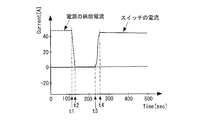
- FIG. 7A and 7B show changes in current and voltage when the power source 5 is disconnected from the superconducting coil 3 and then the protective device 9 is activated.
- the horizontal axis indicates time
- the vertical axis indicates the current value
- the broken line graph indicates the value of the current supplied from the power source 5 to the superconducting coil 3
- the solid line graph indicates the current flowing through the switch 9a. Indicates the value of.
- the switch 9a is closed. As a result, the value of the current flowing through the switch 9a increases rapidly.
- the current value decreases at a low rate of about 3 ⁇ 10 ⁇ 3 A / sec. Therefore, if the current supplied to the superconducting coil 3 before the time point t1 is set to 500 A or more, for example, from t4 Even after 6 hours, the current of 80% or more (400 A or more) still flows through the closed circuit X.
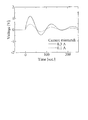
- the horizontal axis indicates time
- the vertical axis indicates the voltage value
- the solid line graph indicates the voltage across the switch 9a in the case of FIG. 7A.
- the power source 5 is disconnected from the superconducting coil 3 and the current flows through the reverse diode 11a, so that the potential difference between both ends of the switch 9a rapidly decreases (the potential difference From time t3 to time t4 ′, the potential difference of the switch 9a suddenly increases (the potential difference suddenly decreases) from time t3 to time t4 ′, and becomes almost zero. Yes.
- FIG. 7B the horizontal axis indicates time
- the vertical axis indicates the voltage value
- the solid line graph indicates the voltage across the switch 9a in the case of FIG. 7A.
- Vc a potential difference between both ends of the superconducting coil 3
- L is an inductance of the superconducting coil 3
- dI / dt a time derivative of the current.
- FIG. 8 shows fluctuations in the value of the current flowing through the superconducting coil 3 when the original state is restored.
- a broken line indicates a voltage value (corresponding to a current value) flowing through the superconducting coil 3 when the short circuit path is released when the current flowing through the short circuit path is 0.1A.
- the solid line indicates the voltage value flowing through the superconducting coil 3 when the short circuit path is released when the current flowing through the short circuit path is 0.3 A.
- the time when the time on the horizontal axis is zero is the time when the short-circuit path is released.
- the reason why the current value of the short-circuit path in each case is low is to prevent the device from being damaged.
- a plurality (for example, five) of superconducting magnet devices 10 are mounted on a plurality of (for example, five) vehicles in a linear motor car. Accordingly, one power source 5 is mounted on each vehicle, but a standby power source is also mounted on the linear motor car.
- the control device central control management device
- the power source 5 is disconnected from the superconducting coil 3 by opening the switch 8.
- the control device electrically connects the normal standby power source as the replacement power source 5 to the superconducting coil 3 in step S ⁇ b> 6 described above, thereby superconducting coil.
- the current supply to 3 is resumed.
- control device takes in the measurement results or detection results of the abnormality of the power source 5 of each vehicle and various electrical quantities (current value, voltage value, etc.) of the electric circuit system including the superconducting magnet device 10 of each vehicle. Then, a series of control operations are executed by preinstalled software.
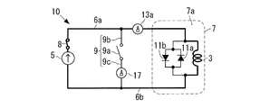
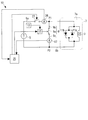
- FIG. 9 is a circuit diagram of the superconducting magnet device 10 according to the first modification of the present invention.
- the detection device 13 includes a voltage detection unit 13d, a voltage comparison unit 13e, and a short circuit signal output unit 13c as illustrated in FIG.
- the voltage detector 13d detects a voltage (potential difference) between two points on the current path (the first current path 6a and the second current path 6b) connecting the power source 5 and the superconducting coil 3. Between these two points, as shown in FIG. 8, an electric resistance 16 having a known electric resistance value may be provided.
- the voltage detector 13d has two voltage levels closer to the power source 5 than the connection point P1 between the first conductive path 9b and the first current path 6a as shown in FIG.
- the magnitude of the voltage at two points on the power source 5 side of the connection point P2 between the conductive path 9c and the second current path 6b is detected.
- the detection device 13 has two other points in the current path connecting the power source 5 and the superconducting coil 3 (for example, one point on the first conductive path 9b and one on the second conductive path 9c). Point) may be detected, and there are various patterns for the two points.
- the voltage comparison unit 13e determines whether the magnitude of the voltage detected by the voltage detection unit 13d does not satisfy the setting condition.
- This setting condition is a condition that the magnitude of the voltage detected by the voltage detector 13d is larger than the threshold value, or a condition that the magnitude of this voltage is within the setting range.
- This threshold value may be zero or a value close to zero, or a predetermined ratio of the magnitude of the voltage detected by the voltage detection unit 13d at normal time (for example, an arbitrary value of 10% or less) Ratio).
- the setting range may be a range of the magnitude of the voltage detected by the voltage detection unit 13d at normal time, or a range close to this range.
- the voltage comparison unit 13e determines that the short-circuit signal output unit 13c outputs a short-circuit signal to the actuator 15 because an abnormal state has occurred. Thereby, the operating device 15 operates the protective device 9 as described above.
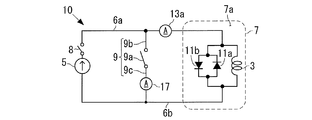
- FIG. 10A is a circuit diagram of a superconducting magnet device 10 according to Modification 2 of the present invention.
- the detection device 13 includes a power supply abnormality detection unit 13f, a stop operation unit 13g, and a short circuit signal output unit 13c as illustrated in FIG. 10A.
- the power supply abnormality detection unit 13f detects a power supply 5 abnormality. For example, the power supply abnormality detection unit 13f detects that the current value supplied by the power supply 5 is larger or smaller than the allowable range as an abnormality of the power supply 5. Alternatively, the power supply abnormality detection unit 13f detects that the abnormality (for example, the flow rate or the temperature) of the refrigerant (cooling water or cooling air) that cools the power supply 5 is outside the allowable range, as an abnormality of the power supply 5. In another example, the power supply abnormality detection unit 13f detects that the temperature of the power supply 5 is equal to or higher than the upper limit value as a power supply 5 abnormality. In yet another example, the power supply abnormality detecting unit 13f detects that the magnetic field in the vicinity of the power supply 5 is larger or smaller than the allowable range as an abnormality of the power supply 5.
- the abnormality for example, the flow rate or the temperature
- the refrigerant cooling water or cooling air
- the stop operation unit 13g stops the current supply from the power source 5 to the superconducting coil 3 when the power source abnormality detection unit 13f detects the abnormality of the power source 5. That is, the stop operation unit 13g electrically disconnects the power source 5 from the superconducting coil 3. For example, the stop operation unit 13g stops the current supply to the superconducting coil 3 by opening the switch 14 provided in the first current path 6a (or the second current path 6b).
- the short-circuit signal output unit 13c when the power supply abnormality detection unit 13f detects the abnormality of the power supply 5, the short-circuit signal output unit 13c outputs a short-circuit signal, so that the operating device 15 forms a short-circuit path as described above. That is, the short circuit signal output unit 13c is abnormal in response to the power supply abnormality detection unit 13f detecting the abnormality of the power supply 5 or in response to the stop operation unit 13g stopping the above-described current supply. A short circuit signal is output to the actuator 15 as the situation occurs.
- the stop operation unit 13g stops the current supply to the superconducting coil 3 by opening the switch 14 described above, Thereafter, the short circuit signal output unit 13c determines whether or not the operation of the protection device 9 is necessary, and outputs a short circuit signal to the operation device 15 when it is determined that this operation is necessary.
- the short-circuit signal output unit 13c operates the short-circuit signal by outputting a signal to that effect to the short-circuit signal output unit 13c. Output to the device 15.
- the abnormality of the cooling container 7 may be that the liquid level of the liquid refrigerant in the internal space 7a of the cooling container 7 is lower than the lower limit value, or may be other abnormality. .
- Such a detection device 13 may be incorporated in the power source 5.
- the stop operation unit 13g may not be provided.
- the short circuit signal output unit 13c outputs a short circuit signal in response to the power supply abnormality detection unit 13f detecting the abnormality of the power source 5.
- the power supply 5 and the superconducting coil 3 do not necessarily have to be separated from each other.
- the power source abnormality detection unit 13f detects the abnormality of the power source 5 and outputs a short circuit signal.
- FIG. 10B shows the configuration of the superconducting magnet device 10 when the safety device 18 is provided.
- the safety device 18 includes, for example, a power supply monitoring unit 18a, an operation unit 18b, and a switch 18c.
- the power monitoring unit 18a detects an abnormality in the power source 5
- the power monitoring unit 18a outputs an operation signal to the operation unit 18b.
- the operating unit 18b operates to open the switch 18c by receiving an operating signal from the operating unit 18b.
- the power supply monitoring unit 18a detects that the current value supplied by the power supply 5 is larger or smaller than an allowable range (for example, an allowable range wider than the allowable range used by the power supply abnormality detection unit 13f) as an abnormality of the power supply 5. To do.
- the power supply monitoring unit 18a has an allowable range in which an abnormality (for example, a flow rate or a temperature) of a refrigerant (cooling water or cooling air) for cooling the power supply 5 is larger than an allowable range (for example, the allowable range used by the power supply abnormality detection unit 13f). ) It is detected as an abnormality of the power supply 5 that it has gone outside.
- the power supply monitoring unit 18a detects that the temperature of the power supply 5 has reached an upper limit value (for example, an upper limit value higher than the upper limit value used by the power supply abnormality detection unit 13f) as an abnormality of the power supply 5. .
- the power supply monitoring unit 18a may be omitted, and the operation unit 18b may operate to close the switch 18c in response to the power supply abnormality detection unit 13f detecting the abnormality of the power supply 5.
- Superconducting coil 3 may be used in combination with other coils.
- a low temperature superconducting coil 31 formed of a low temperature superconducting wire is disposed outside the superconducting coil 3 in the internal space 7 a of the cooling container 7.
- the superconducting coil 3 is indicated by a bold line.
- the superconducting coil 3 and the low-temperature superconducting coil 31 are arranged coaxially in the internal space 7a.
- a circuit for supplying current to the low-temperature superconducting coil 31 ie, the diode 33, the power source 35, and the permanent switch 37 in FIG. 11
- the circuit for supplying current to the superconducting coil 3 are independent of each other.
- the internal space 7a is cooled below the transition temperature of the low-temperature superconducting wire of the low-temperature superconducting coil 31 by, for example, liquid helium.
- the configuration and function of the low temperature superconducting coil 31, diode 33, power source 35, permanent switch 37, and heater 39 are the same as those of the low temperature superconducting coil 31, diode 33, power source 35, permanent It may be the same as the switch 37 and the heater 39.
- the superconducting coil 31 can continue to generate a magnetic field while the power source 35 is disconnected from the low temperature superconducting coil 31. It is.
- the power source 35 may be connected to the low temperature superconducting coil 31.
- the reverse diode 11a described above may be omitted.
- the actuator 15 closes the switch 9a before the current starts to flow through the reverse diode 11a. If possible, the reverse diode 11a may be omitted.
- the protection device 9 may be manually operated to form the above-described short-circuit path.
- an operation unit for example, a button or a lever
- the switch 9a may be closed or opened by operating the operation unit by a person.
- the switch 9a is closed by manual operation instead of steps S3 to S5 after step S2. Maintenance is performed in this state. After the maintenance is completed, steps S6 to S8 are performed.
- the superconducting coil 3 can be maintained in the superconducting state until the liquid refrigerant in the cooling container 7b is exhausted.
- the detection device 13 may be omitted, but the detection device 13 may also be provided and the protection device 9 may be operated by the detection device 13 and the operation device 15.
- a low temperature superconducting coil formed of a low temperature superconducting wire may be connected in series to the superconducting coil 3 described above.
- a low-temperature superconducting coil is disposed together with the superconducting coil 3 in the internal space 7a of the cooling vessel 7, and the internal space 7a is cooled to a temperature lower than the transition temperature of the low-temperature superconducting coil.
- the low temperature superconducting coil is disposed in another cooling container that is cooled to a temperature lower than the transition temperature of the low temperature superconducting coil.
- one or a plurality of superconducting coils formed of high-temperature superconducting wires may be connected to the superconducting coil 3 in series.
- the protection device 9 short-circuits both ends of a part or the whole (superconducting coil 3) of these superconducting coils constituting the superconducting magnet device 10.
- the superconducting coil 3 may be formed by connecting a plurality of superconducting coils formed of high-temperature superconducting wires in series with each other.
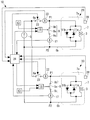
- FIG. 12 shows a configuration of a superconducting magnet device 10 according to the modified example 7.
- the superconducting magnet device 10 has a plurality of magnetic field generation devices 20.
- the number of the magnetic field generation devices 20 included in the superconducting magnet device 10 is two in the figure, but may be any number of three or more.
- Each magnetic field generation device 20 includes the superconducting coil 3, the cooling vessel 7, the protection device 9, the reverse diode 11a, and the forward diode 11b described above.
- the superconducting magnet device 10 has one power source 5 shared by a plurality of magnetic field generation devices 20.
- the superconducting magnet device 10 is provided in each magnetic field generation device 20, and in the magnetic field generation device 20, a short-circuit current detection for detecting a value of a current flowing through a closed circuit including the superconducting coil 3 and the closed switch 9a.
- the unit 17 is provided.
- the value of the detected current means the magnitude (hereinafter the same).
- the superconducting magnet device 10 is provided in each magnetic field generating device 20 and detects the value of the current flowing through the superconducting coil 3 or the value of the magnetic field generated by the superconducting coil 3 with the switch 9a closed.
- a coil state detector 17 or 28 is provided. When this coil state detection unit detects the value of the current flowing through the superconducting coil 3, this coil state detection unit may be the short-circuit current detection unit 17, but is not limited thereto.
- the coil state detection unit detects the value of the magnetic field generated by the superconducting coil 3, the coil state detection unit is a magnetic field detection unit 28 provided separately from the short-circuit current detection unit 17.
- the value of the current or magnetic field detected by the coil state detection unit 17 or 28 means the magnitude (the same applies hereinafter).
- the superconducting magnet device 10 is provided in each magnetic field generation device 20, and the magnetic field generation device 20 from the power source 5 (that is, the connection point P1 between the first current path 6a and the first conductive path 9b in FIG. 12).
- a supply current detector 22 is provided for detecting the value of the current supplied to.
- the value of the detected current means the magnitude (hereinafter the same).
- the supply current detector 22 is upstream of the connection point P1 in the first current path 6a, or downstream of the connection point P2 of the second current path 6b and the second conductive path 9c in the second current path 6b. Provided on the side.
- the current detection unit 13 a may function as the supply current detection unit 22.
- various devices for example, a device using a measured value of a magnetic field
- the superconducting magnet device 10 is provided in each magnetic field generation device 20, a closed position where a current is supplied from the power source 5 to the magnetic field generation device 20 (connection point P ⁇ b> 1), and the magnetic field generation device 20 ( A current supply switch 23 is provided which is operated between the open position where the connection point P1) is disconnected.
- the superconducting magnet device 10 includes a control device 24.
- the control device 24 controls the operating device 15 based on the detected current value or the detected magnetic field value by the supply current detection unit 22, the coil state detection unit 17 or 28, or the short-circuit current detection unit 17, thereby providing a current supply switch.
- the positions of the switch 23 and the switch 9a are switched between a closed position and an open position. That is, in each magnetic field generation device 20, the control device 24 sets the detected current value or the detected magnetic field value by the coil state detection unit 17 or 28 to the reference value (positive value) in a state where the switch 9 a of the protection device 9 is closed. When the following occurs, the current supply switch 23 of the magnetic field generation device 20 is moved to the closed position.
- the control device 24 switches the protection device 9 when the current value detected by the short-circuit current detection unit 17 becomes equal to or less than the above set value in the process of increasing the current supplied from the power source 5 to the magnetic field generation device 20.
- the protection device 9 is operated.
- the current supply switch 23 is operated. Move to the open position.
- connection point P1 The value of the current passed from the power supply 5 to the magnetic field generator 20 (connection point P1) is gradually reduced.
- the control device 24 controls the power supply 5 so as to gradually decrease the current value.
- each magnetic field generation device 20 By performing the above (1) to (5) for each magnetic field generation device 20, in each magnetic field generation device 20, the current supply switch 23 is in the open position, the switch 9a is in the closed position, and superconductivity
- the above-mentioned rated current value (or a current larger than the reference value) is flowing in a closed circuit (corresponding to the thick line circuit in FIG. 6A) including the coil 3 and the switch 9a (or by the coil state detection unit 28).
- the detected magnetic field value becomes larger than the reference value).
- This state is set as a reference state. From this reference state, the superconducting magnet device 10 operates in the following order (6) to (11).
- the reference value is smaller than the rated current value.
- the control device 24 controls the magnetic field generation device.
- the 20 current supply switches 23 are operated to the closed position.
- the following (7) to (11) are performed on the magnetic field generation apparatus 20.
- a current is supplied from the power source 5 to the superconducting coil 3.
- the power source 5 gradually increases the value of the current.
- the control device 24 controls the power supply 5 so as to gradually increase the value of the current.
- the switch 9a is in the closed position.
- the power supply 5 gradually increases the value of the current (for example, the control device 24 controls the power supply 5 so as to gradually increase the value of the current), thereby detecting the supply current
- the control device 24 operates the switch 9a to the closed position.
- the control device 24 controls the power supply 5 so as to gradually decrease the current value.
- Such a superconducting magnet device 10 can be provided in a linear motor car. That is, the superconducting magnet device 10 is provided in a linear motor car (running vehicle), and the magnetic field generated by the plurality of superconducting coils 3 of the superconducting magnet device 10 is used for propulsion and levitation of the linear motor car.
- the above operations (6) to (11) may be performed while the linear motor car is traveling.
- a plurality of such superconducting magnet devices 10 may be provided in a linear motor car.
- the protection device 9 and the short-circuit current detection unit 17 are provided outside the cooling container 7 in FIG. 12, but may be provided in the internal space 7 a of the cooling container 7.
- the number of power supplies 5 used can be suppressed. Further, in each magnetic field generating device 20, when the magnitude of the current flowing through the superconducting coil 3 or the magnitude of the magnetic field generated by the superconducting coil 3 becomes equal to or less than the reference value, the current is supplied from the power source 5 to the magnetic field generating device 20. Therefore, the use frequency of the power source 5 can be suppressed. Furthermore, even when the power source 5 is not connected to the superconducting coil 3, the current decrease can be suppressed or reduced.
- each magnetic field generation device 20 is provided with the detection device 13 and the operation device 15 described above. Therefore, when an abnormal state occurs during the operation (2) or (9) described above, the protection device 9 forms the above-described short-circuit path by the inspection device 13 and the operation device 15. Therefore, the protection function of the protection device 9 can be utilized. Also in the modified example 7, the functions of the short-circuit current comparison unit 19 and the release signal output unit 21 described above are incorporated in the control device 24. Therefore, according to (8) above, the opening operation control of the switch 9a based on the short-circuit current detection function of the short-circuit current detection unit 17 can be executed.
- the power source 5 in this case is not provided in the linear motor car (that is, the traveling vehicle), but is provided in the vehicle stop position (stationary structure), and the superconducting magnet device 10 excluding the power source 5 is provided in the linear motor car.
- the magnetic field generated by the superconducting coil 3 of the superconducting magnet device 10 is used for propulsion and levitation of the linear motor car.
- the linear motor car can suppress a decrease in the current flowing through the superconducting coil 3.
- the protection device 9 has a function of protecting the circulating current in the sense of suppressing a decrease in circulating current.
- the superconducting magnet device 10 includes a supply current detection unit 26, a current supply switch 27, and a control device 25.
- the supply current detection unit 26 determines the value (magnitude) of the current supplied from the power supply 5 to the superconducting coil 3 (that is, the connection point P1 between the first current path 6a and the first conductive path 9b in FIG. 13). To detect.
- the configuration and arrangement of the supply current detection unit 26 are the same as those of the supply current detection unit 22 of the seventh modification.
- the current supply switch 27 operates between a closed position where current is supplied from the power source 5 to the superconducting coil 3 (connection point P1) and an open position where the superconducting coil 3 (connection point P1) is disconnected from the power source 5. Be made.
- the configuration and arrangement of the current supply switch 27 are the same as those of the current supply switch 23 of the seventh modification.
- the control device 25 switches the positions of the current supply switch 27 and the switch 9a between the closed position and the open position by controlling the operating device 15 based on the current value detected by the supply current detector 26.
- connection point P1 the value of the current flowing from the power source 5 to the superconducting coil 3 (connection point P1) is gradually reduced.
- the control device 25 controls the power supply 5 so as to gradually decrease the current value.
- (G) Current is supplied from the power source 5 to the superconducting coil 3 with the switch 9a in the closed position.
- the current value is gradually increased.
- the control device 25 controls the power supply 5 so as to gradually increase the value of the current.
- the power supply 5 gradually increases the value of the current (for example, the control device 25 controls the power supply 5 so as to gradually increase the value of the current), thereby detecting the supply current
- the control device 25 operates the switch 9a to the closed position.
- connection point P1 the value of the current flowing from the power source 5 to the superconducting coil 3 (connection point P1) is gradually reduced.
- the control device 25 controls the power supply 5 so as to gradually decrease the current value.
- the protective device 9 and the short-circuit current detection unit 17 are provided outside the cooling container 7 in FIG. 13, but may be provided in the internal space 7 a of the cooling container 7.
- the detection device 13 and the operation device 15 are provided in the superconducting magnet device 10 as described above. Therefore, when an abnormal state occurs during the operation (b) or (i) described above, the protection device 9 forms the above-described short-circuit path by the inspection device 13 and the operation device 15. Therefore, the protection function of the protection device 9 can be utilized. Also in the modified example 8, in FIG. 13, the functions of the short-circuit current comparison unit 19 and the release signal output unit 21 are incorporated in the control device 25. Therefore, the opening operation control of the switch 9a based on the short-circuit current detection function of the short-circuit current detection unit 17 can be executed by the above (h).
- 3 superconducting coil 5 power source (constant current source), 6a first current path, 6b second current path, 7 cooling container, 7a inner space, 7b inner container, 7c outer container, 7d vacuum layer, 7e refrigerator, 7f Refrigerator, 8 switch, 9 protection device, 9a switch, 9b 1st conductive path, 9c 2nd conductive path, 10 superconducting magnet device, 11a reverse diode, 11b forward diode, 13 detector, 13a supply current Detection part (ammeter), 13b Supply current comparison part, 13c Short circuit signal output part, 13d Voltage detection part, 13e Voltage comparison part, 13f Power supply abnormality detection part, 13g Stop operation part, 14 switch, 15 actuator, 16 electrical resistance 17 Short circuit current detection unit (coil state detection unit) 18 Safety device 18a Power supply monitoring unit 18b Actuation unit 8c switch, 19 short circuit current comparison unit, 20 magnetic field generation device, 21 release signal output unit, 22 supply current detection unit, 23 current supply switch, 24 control device, 25 control device, 26 supply current detection unit
Landscapes
- Engineering & Computer Science (AREA)
- Power Engineering (AREA)
- Containers, Films, And Cooling For Superconductive Devices (AREA)
- Magnetic Resonance Imaging Apparatus (AREA)
Priority Applications (1)
| Application Number | Priority Date | Filing Date | Title |
|---|---|---|---|
| US15/951,263 US11171479B2 (en) | 2015-10-16 | 2018-04-12 | Superconducting magnet device and method for limiting current decrease in case of abnormality therein |
Applications Claiming Priority (2)
| Application Number | Priority Date | Filing Date | Title |
|---|---|---|---|
| JP2015-204497 | 2015-10-16 | ||
| JP2015204497A JP6601797B2 (ja) | 2015-10-16 | 2015-10-16 | 超伝導磁石装置とその異常時の電流低下抑制方法 |
Related Child Applications (1)
| Application Number | Title | Priority Date | Filing Date |
|---|---|---|---|
| US15/951,263 Continuation US11171479B2 (en) | 2015-10-16 | 2018-04-12 | Superconducting magnet device and method for limiting current decrease in case of abnormality therein |
Publications (1)
| Publication Number | Publication Date |
|---|---|
| WO2017065151A1 true WO2017065151A1 (ja) | 2017-04-20 |
Family
ID=58518178
Family Applications (1)
| Application Number | Title | Priority Date | Filing Date |
|---|---|---|---|
| PCT/JP2016/080182 Ceased WO2017065151A1 (ja) | 2015-10-16 | 2016-10-12 | 超伝導磁石装置とその異常時の電流低下抑制方法 |
Country Status (3)
| Country | Link |
|---|---|
| US (1) | US11171479B2 (enExample) |
| JP (1) | JP6601797B2 (enExample) |
| WO (1) | WO2017065151A1 (enExample) |
Families Citing this family (7)
| Publication number | Priority date | Publication date | Assignee | Title |
|---|---|---|---|---|
| RU2745295C1 (ru) * | 2018-01-30 | 2021-03-23 | Токемек Энерджи Лтд | Контрольно-измерительное устройство для криогенной системы |
| CA3120822A1 (en) * | 2018-11-22 | 2020-05-28 | Tokamak Energy Ltd | Rapid dump of partially insulated superconducting magnet |
| CN111751758A (zh) * | 2020-06-15 | 2020-10-09 | 中国第一汽车股份有限公司 | 一种汽车线束短路检测装置及方法 |
| CN114792594B (zh) * | 2022-05-12 | 2023-11-21 | 中国科学院电工研究所 | 一种超导悬浮磁场衰减抑制装置及抑制方法 |
| WO2025108788A1 (en) * | 2023-11-21 | 2025-05-30 | Koninklijke Philips N.V. | System and method for detecting superconductive state transition |
| EP4560342A1 (en) * | 2023-11-21 | 2025-05-28 | Koninklijke Philips N.V. | System and method for detecting superconductive state transition |
| CN120748882B (zh) * | 2025-09-04 | 2025-12-05 | 西安聚能超导磁体科技股份有限公司 | 一种大尺寸磁控直拉单晶硅用超导磁体的磁场切换系统 |
Citations (2)
| Publication number | Priority date | Publication date | Assignee | Title |
|---|---|---|---|---|
| JP2010524219A (ja) * | 2007-04-02 | 2010-07-15 | シーメンス ピーエルシー | 準永久超電導磁石におけるクエンチ保護および減衰安定化のための装置 |
| US20140185165A1 (en) * | 2012-12-27 | 2014-07-03 | General Electric Company | Superconducting coil system and methods of assembling the same |
Family Cites Families (6)
| Publication number | Priority date | Publication date | Assignee | Title |
|---|---|---|---|---|
| US5862028A (en) * | 1996-05-24 | 1999-01-19 | Northrop Grumman Corporation | Method and apparatus for detecting quenching of a coil for a superconducting magnet |
| US7342757B2 (en) * | 2004-06-28 | 2008-03-11 | General Electric Company | System and method for quench protection of a superconductor |
| US6900714B1 (en) * | 2004-06-30 | 2005-05-31 | General Electric Company | System and method for quench and over-current protection of superconductor |
| JP4542573B2 (ja) * | 2007-08-07 | 2010-09-15 | 株式会社日立製作所 | アクティブシールド型の超電導電磁石装置および磁気共鳴イメージング装置 |
| CN102412047B (zh) * | 2010-09-21 | 2014-07-30 | 通用电气公司 | 超导磁体及超导磁体系统 |
| JP2014000346A (ja) | 2012-06-21 | 2014-01-09 | Hitachi Medical Corp | 超伝導電磁石装置及び磁気共鳴画像装置 |
-
2015
- 2015-10-16 JP JP2015204497A patent/JP6601797B2/ja active Active
-
2016
- 2016-10-12 WO PCT/JP2016/080182 patent/WO2017065151A1/ja not_active Ceased
-
2018
- 2018-04-12 US US15/951,263 patent/US11171479B2/en not_active Expired - Fee Related
Patent Citations (2)
| Publication number | Priority date | Publication date | Assignee | Title |
|---|---|---|---|---|
| JP2010524219A (ja) * | 2007-04-02 | 2010-07-15 | シーメンス ピーエルシー | 準永久超電導磁石におけるクエンチ保護および減衰安定化のための装置 |
| US20140185165A1 (en) * | 2012-12-27 | 2014-07-03 | General Electric Company | Superconducting coil system and methods of assembling the same |
Also Published As
| Publication number | Publication date |
|---|---|
| JP2017076736A (ja) | 2017-04-20 |
| JP6601797B2 (ja) | 2019-11-06 |
| US20180233899A1 (en) | 2018-08-16 |
| US11171479B2 (en) | 2021-11-09 |
Similar Documents
| Publication | Publication Date | Title |
|---|---|---|
| JP6601797B2 (ja) | 超伝導磁石装置とその異常時の電流低下抑制方法 | |
| US8400747B2 (en) | Superconducting coil, superconducting magnet, and method of operating superconducting magnet | |
| US8693146B2 (en) | Quench detection system for a superconductor fault current limiter | |
| JP5931181B2 (ja) | 超電導マグネットの順序だったランダウンのための方法および装置 | |
| US7342757B2 (en) | System and method for quench protection of a superconductor | |
| EP3987555B1 (en) | Quench protection for high temperature superconducting (hts) leads | |
| CN103636091B (zh) | 超导故障电流限制器回复系统 | |
| JP5656734B2 (ja) | 並列巻線を有する超電導磁石および超電導磁石システム | |
| CN111794913B (zh) | 超导风力涡轮发电机的自动斜变和能量释放的系统和方法 | |
| US20240155951A1 (en) | Superconducting magnet device, nmr device, and mri device | |
| CN101572401A (zh) | 涉及关于动力应用的超导产生器的保护的系统和方法 | |
| JP2019220524A (ja) | 超電導磁石およびその保護方法 | |
| WO2022168483A1 (ja) | 超伝導磁石装置、磁気共鳴イメージング装置および超伝導磁石の減磁方法 | |
| JP6794146B2 (ja) | 高温超電導磁石装置 | |
| JP7428515B2 (ja) | 永久電流スイッチ、超電導電磁石装置、および超電導電磁石装置の永久電流運転方法 | |
| JP5039985B2 (ja) | 変圧器型超電導限流器 | |
| JP2011029227A (ja) | コイル装置、保護装置及び誘導電圧抑制方法 | |
| Ding et al. | Factory acceptance test of 50-ka hts current leads for the iter cs magnet test application | |
| Hobl et al. | HTc current leads in commercial magnet systems applying Bi 2212 MCP BSCCO material | |
| Mumford | Superconducting fault current limiters | |
| Muratore et al. | Magnetic field measurements of an HTS retrofit synchrotron dipole | |
| JPH01298921A (ja) | 連係装置 | |
| WO2024048179A1 (ja) | 超電導磁石装置、及び核磁気共鳴診断装置 | |
| Bermond et al. | Fault Current Limiter for Temporal Stabilization Process of Very High Fields in NMR or MRI | |
| Neumueller et al. | Economically viable fault current limiters using YBCO coated conductors |
Legal Events
| Date | Code | Title | Description |
|---|---|---|---|
| 121 | Ep: the epo has been informed by wipo that ep was designated in this application |
Ref document number: 16855405 Country of ref document: EP Kind code of ref document: A1 |
|
| NENP | Non-entry into the national phase |
Ref country code: DE |
|
| 122 | Ep: pct application non-entry in european phase |
Ref document number: 16855405 Country of ref document: EP Kind code of ref document: A1 |