WO2017065151A1 - Superconducting magnet device and method for limiting current decrease in case of abnormality therein - Google Patents
Superconducting magnet device and method for limiting current decrease in case of abnormality therein Download PDFInfo
- Publication number
- WO2017065151A1 WO2017065151A1 PCT/JP2016/080182 JP2016080182W WO2017065151A1 WO 2017065151 A1 WO2017065151 A1 WO 2017065151A1 JP 2016080182 W JP2016080182 W JP 2016080182W WO 2017065151 A1 WO2017065151 A1 WO 2017065151A1
- Authority
- WO
- WIPO (PCT)
- Prior art keywords
- current
- short
- superconducting coil
- superconducting
- circuit
- Prior art date
Links
Images


Classifications
-
- H—ELECTRICITY
- H02—GENERATION; CONVERSION OR DISTRIBUTION OF ELECTRIC POWER
- H02H—EMERGENCY PROTECTIVE CIRCUIT ARRANGEMENTS
- H02H7/00—Emergency protective circuit arrangements specially adapted for specific types of electric machines or apparatus or for sectionalised protection of cable or line systems, and effecting automatic switching in the event of an undesired change from normal working conditions
- H02H7/001—Emergency protective circuit arrangements specially adapted for specific types of electric machines or apparatus or for sectionalised protection of cable or line systems, and effecting automatic switching in the event of an undesired change from normal working conditions for superconducting apparatus, e.g. coils, lines, machines
-
- H—ELECTRICITY
- H01—ELECTRIC ELEMENTS
- H01F—MAGNETS; INDUCTANCES; TRANSFORMERS; SELECTION OF MATERIALS FOR THEIR MAGNETIC PROPERTIES
- H01F6/00—Superconducting magnets; Superconducting coils
- H01F6/02—Quenching; Protection arrangements during quenching
-
- H—ELECTRICITY
- H01—ELECTRIC ELEMENTS
- H01F—MAGNETS; INDUCTANCES; TRANSFORMERS; SELECTION OF MATERIALS FOR THEIR MAGNETIC PROPERTIES
- H01F6/00—Superconducting magnets; Superconducting coils
- H01F6/06—Coils, e.g. winding, insulating, terminating or casing arrangements therefor
-
- H—ELECTRICITY
- H02—GENERATION; CONVERSION OR DISTRIBUTION OF ELECTRIC POWER
- H02H—EMERGENCY PROTECTIVE CIRCUIT ARRANGEMENTS
- H02H3/00—Emergency protective circuit arrangements for automatic disconnection directly responsive to an undesired change from normal electric working condition with or without subsequent reconnection ; integrated protection
- H02H3/12—Emergency protective circuit arrangements for automatic disconnection directly responsive to an undesired change from normal electric working condition with or without subsequent reconnection ; integrated protection responsive to underload or no-load
-
- Y—GENERAL TAGGING OF NEW TECHNOLOGICAL DEVELOPMENTS; GENERAL TAGGING OF CROSS-SECTIONAL TECHNOLOGIES SPANNING OVER SEVERAL SECTIONS OF THE IPC; TECHNICAL SUBJECTS COVERED BY FORMER USPC CROSS-REFERENCE ART COLLECTIONS [XRACs] AND DIGESTS
- Y02—TECHNOLOGIES OR APPLICATIONS FOR MITIGATION OR ADAPTATION AGAINST CLIMATE CHANGE
- Y02E—REDUCTION OF GREENHOUSE GAS [GHG] EMISSIONS, RELATED TO ENERGY GENERATION, TRANSMISSION OR DISTRIBUTION
- Y02E40/00—Technologies for an efficient electrical power generation, transmission or distribution
- Y02E40/60—Superconducting electric elements or equipment; Power systems integrating superconducting elements or equipment
Definitions
- the present invention relates to a superconducting magnet device comprising a superconducting coil formed of a high-temperature superconducting wire and a superconducting coil for generating a magnetic field by supplying a current to the superconducting coil.
- the present invention also relates to a method for suppressing a decrease in current when the superconducting magnet device is abnormal.
- the superconducting magnet device can generate a strong magnetic field by including a superconducting coil capable of flowing a large current.
- a superconducting magnet device can be used as a magnet for NMR (nuclear magnetic resonance) or a magnet for MRI (magnetic resonance imaging).
- the superconducting magnet device can also be used in other applications (for example, a linear motor car).
- superconductivity may be expressed as superconductivity, it is expressed as superconductivity in the present application.
- a superconducting magnet device has been put into practical use, for example, as an NMR magnet, using a superconducting coil formed of a low-temperature superconducting wire.
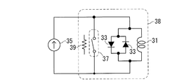
- the superconducting magnet device includes a superconducting coil 31 formed of a low-temperature superconducting wire, a diode 33 connected in parallel to the superconducting coil 31, a power supply 35 for supplying current to the superconducting coil 31, and a permanent current switch. 37 and a heater 39 for heating.
- the permanent current switch 37 is formed of a low temperature superconducting wire. Since this low-temperature superconducting wire 37 functions as a switch as will be described later, in FIG. 1A to FIG. 1C, it is represented by a switch symbol. Further, a closed circuit (a thick line circuit in FIG.
- this closed circuit is referred to as a superconducting closed circuit.
- the superconducting magnet apparatus of FIGS. 1A to 1C can generate a magnetic field in a permanent current mode in which current does not decay by the following procedure.
- the superconducting coil 31, the diode 33, and the permanent current switch 37 are placed in liquid helium in the cooling vessel 38. Thereby, the above-mentioned superconducting closed circuit is cooled below the transition temperature.
- the transition temperature is a temperature at which the transition from the normal state to the superconducting state (hereinafter the same). Therefore, the superconducting closed circuit is in a superconducting state with zero electrical resistance.
- the permanent current switch 37 is heated by the heater 39 to a temperature higher than the above transition temperature.
- the permanent current switch 37 (superconducting wire) transitions to the normal conducting state, and the superconducting closed circuit is disconnected. In other words, the permanent current switch 37 is turned off (the state shown in FIG. 1A).
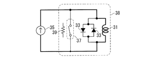
- the current flowing through the permanent current switch 37 increases.
- the value of the current flowing from the permanent current switch 37 to the superconducting coil 31 becomes the above-described rated current value.
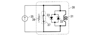
- This current circulates in the superconducting closed circuit described above without being attenuated. That is, the current flows through the thick line in this figure as shown in FIG. 1C.
- the superconducting magnet device is in a permanent current mode in which the superconducting coil 31 generates a magnetic field without a power source.
- a superconducting magnet device that generates a magnetic field in the permanent current mode as described above is described in, for example, Patent Document 1 below.
- the superconducting magnet device of FIGS. 1A to 1C uses a low-temperature superconducting wire, it is desired to realize a superconducting magnet device using a high-temperature superconducting wire.
- the high-temperature superconducting wire mainly has the following two advantages.
- the transition temperature of the high-temperature superconducting wire is, for example, not less than the boiling point (77K) of liquid nitrogen and higher than the transition temperature of the low-temperature superconducting wire.
- a large current can be passed through the high-temperature superconducting wire even in a high magnetic field.
- a superconducting coil formed of a high-temperature superconducting wire can be brought into a superconducting state by using, for example, liquid nitrogen or a small refrigerator.
- the superconducting coil of the high-temperature superconducting wire can obtain a strong magnetic field by flowing a large current through the superconducting coil of the high-temperature superconducting wire even in a high magnetic field (even when the magnetic field generated from the surroundings is high).
- a superconducting magnet device having a superconducting coil of a high-temperature superconducting wire can generate a magnetic field having the same strength with a smaller configuration than when a low-temperature superconducting wire is used.
- the superconducting magnet device includes a superconducting coil 41 formed of a high-temperature superconducting wire, a diode 43 connected in parallel to the superconducting coil 41, and a power supply 45 for supplying current to the superconducting coil 41.
- the circuit portion including the superconducting coil 41 and the diode 43 is heated at a high temperature by, for example, a refrigerant (that is, liquid nitrogen, liquid hydrogen, liquid argon, liquid helium, or other cryogenic refrigerant) in the cooling container 47 or a small refrigerator. It is cooled below the transition temperature of the superconducting wire.
- a refrigerant that is, liquid nitrogen, liquid hydrogen, liquid argon, liquid helium, or other cryogenic refrigerant
- the current flowing in the closed circuit including the diode 43 and the superconducting coil 41 prevents the current in the superconducting coil 41 from becoming zero instantaneously.
- the current rapidly decreases to zero even if not instantaneously.
- at least one (for example, all) of the following problems (A), (B), and (C) occurs.
- a large inductance for example, 10H to 2000H, preferably 50H to 1000H
- the superconducting portion is made into a multifilament.
- high-temperature superconducting wires including wires other than tape, are difficult to multifilament or cannot be multifilamented as low-temperature superconducting wires. If it is not multifilament or if its amount is small, hysteresis loss occurs due to the shielding current in a variable magnetic field.
- the high-temperature superconducting coil 41 has a larger hysteresis loss than the low-temperature superconducting coil, and heat is generated due to a larger hysteresis loss in the high-temperature superconducting coil 41 during magnet excitation and demagnetization (increase or decrease in magnet current). appear.
- the temperature of a part of the superconducting coil 41 increases locally at the place due to heat generated by the hysteresis loss, and in some cases exceeds the critical temperature. Since a current is applied, the critical temperature at this time is significantly smaller than the critical temperature when no magnetic field is applied and no current is applied.
- the rate at which the current is reduced by the protection circuit using the diode 43 is very high, and the local thermal runaway may occur due to the hysteresis loss unique to the high-temperature superconducting coil 41 if only the protection circuit using the diode 43 is used.
- the inventor of the present application has found.
- the inventor of the present application has found that the superconducting magnet device using a superconducting coil formed of a high-temperature superconducting wire has a power supply exceeding an abnormal state or for other reasons (for example, power supply maintenance). It has been found that it is desirable to suppress a decrease in the current flowing through the superconducting coil when it is disconnected from the conducting coil. That is, when the power source is disconnected from the superconducting coil, if the decrease in the value of the current flowing through the superconducting coil can be suppressed, the problems (A), (B), and (C) can be solved. Found by the person.
- a superconducting magnet device Installed a superconducting magnet device, (B) generating a magnetic field in the superconducting coil by flowing a current from the power source through the superconducting coil in a superconducting state; (C) When an abnormality of the superconducting magnet device is detected after generating the magnetic field according to (B), or when the power source and the superconducting coil are separated from each other, the protection device Provided is a method for suppressing a current drop in a superconducting magnet device that forms a short-circuit path.
- the superconducting coil can continue to generate a magnetic field for a while (for example, 6 hours to several days).
- the value of the current flowing through the above-described closed circuit when the restoration is completed Is still big enough. Therefore, it is not necessary to gradually increase the value of the current flowing through the superconducting coil from zero when the current supply from the power source is resumed after the restoration is completed, so that the current value is gradually increased to the target value. Takes less time to complete. For example, when the above-described abnormal state occurs at midnight, the current value can be increased to the target value in a short time even if the recovery is completed in the morning of the day.
- the current supply from the power source to the superconducting coil is started, and when it is detected that the magnitude of the current flowing through the short-circuit path is less than the set value, the short-circuit path is canceled.
- the current value of the superconducting coil can be prevented from fluctuating due to the current in the short circuit path.
- a superconducting coil formed of a high-temperature superconducting wire;
- a superconducting magnet device comprising a protective device capable of forming a short-circuit path that short-circuits both ends of the superconducting coil.
- a superconducting magnet device is provided. That is, the superconducting magnet device of the present invention may not include a power supply as a constituent feature.
- a short circuit path can be formed by the protective device.
- a closed circuit including a superconducting coil and a short circuit path is formed.
- the current flowing through the superconducting coil circulates in this closed circuit. Since the electric resistance of the closed circuit is very small, it is possible to suppress a decrease in current circulating in the closed circuit.
- such a superconducting magnet device can suppress the frequency of use of the power supply by utilizing the protection function of the protection device that suppresses a decrease in current in the event of an abnormality, for example, according to the usage mode (for example, Modification Example 8 described later). Is possible. In this case, even when the power source is not connected to the superconducting coil, the decrease in current can be suppressed or reduced.
- the above-described superconducting magnet device can be configured as follows, for example.
- the superconducting magnet device of (i) or (ii) above is When detecting that the superconducting magnet device is in an abnormal state, a detection device that outputs a short circuit signal; And an actuating device that activates the protection device so that the protection device forms the short-circuit path when the short-circuit signal is output.
- the protection device includes a switch, and the short circuit path is formed by closing the switch.
- the power source is a constant current source that supplies a constant current to the superconducting coil, and the constant current is Flowing from one end of the superconducting coil to the other end,
- the above-described superconducting magnet device includes a reverse diode connected in antiparallel to the superconducting coil.
- the protective device forms a short circuit path, so that the current path of the superconducting coil is switched from the reverse diode path to the short circuit path. Therefore, the amount of heat generated by the reverse diode can be kept very small.
- the detection device comprises: A supply current detector for detecting the magnitude of the current supplied to the superconducting coil by the power source; A supply current comparison unit for determining whether the magnitude of the current detected by the supply current detection unit does not satisfy the setting condition; And a short-circuit signal output unit that outputs the short-circuit signal when the abnormal state occurs when the supply current comparison unit determines that the magnitude of the current does not satisfy the set condition.
- the short circuit signal output unit outputs a short circuit signal, thereby forming a short circuit path.
- an abnormal state for example, a power failure
- the detection device comprises: A voltage detection unit for detecting a magnitude of a voltage between two points of a current path connecting the power source and the superconducting coil; A voltage comparison unit for determining whether the magnitude of the voltage detected by the voltage detection unit no longer satisfies the setting condition; And a short-circuit signal output unit that outputs the short-circuit signal when the abnormal state occurs when the voltage comparison unit determines that the magnitude of the voltage no longer satisfies the set condition.
- the detection device includes: A power supply abnormality detection unit for detecting the power supply abnormality; A short-circuit signal output unit that outputs the short-circuit signal when the abnormal state occurs when the power-supply abnormality detection unit detects the abnormality of the power source.
- the short circuit signal output unit outputs a short circuit signal. Thereby, the above-mentioned short circuit path is formed.
- the superconducting magnet device is A short-circuit current detector that detects the magnitude of the current flowing through the short-circuit path formed by the protection device;
- a short-circuit current comparator for determining whether the magnitude of the current detected by the short-circuit current detector is equal to or less than a set value;
- a release signal output unit that outputs a short-circuit release signal to the operating device is provided, and the operating device receives the short-circuit release signal or the short-circuit release signal And the short-circuit release command are received, the short-circuit path by the protection device is released.
- the superconducting magnet device is A plurality of magnetic field generation devices having the superconducting coil and the protection device,
- the power source is shared by the plurality of magnetic field generation devices,
- a coil state detection unit that is provided in each magnetic field generation device and detects the magnitude of the current flowing through the superconducting coil or the magnitude of the magnetic field generated by the superconducting coil;
- a current supply switch provided in each magnetic field generation device and operated between a closed position where current is supplied from the power source to the magnetic field generation device and an open position where the magnetic field generation device is disconnected from the power source;
- the current supply switch of the magnetic field generation device is closed.
- a control device to be operated.
- one power source is provided for a plurality of superconducting coils, and when the current of the superconducting coil falls below the reference value, the current is supplied from the power source to the superconducting coil.
- the frequency of use and the number of uses can be reduced.
- the protection function of the protection device that suppresses a decrease in current in the event of an abnormality can be utilized (for example, Modification Example 7 described later). Further, even when the power source is not connected to the superconducting coil, the decrease in current can be suppressed or reduced.
- FIG. 1A It is a circuit diagram of a superconducting magnet device using a low-temperature superconducting wire.
- a path through which a current flows is shown in the circuit diagram of FIG. 1A.
- 1B shows another path through which a current flows in the circuit diagram of FIG. 1A.
- the structural example of a freezing container is shown.
- the other structural example of a freezing container is shown.
- the other structural example of a freezing container is shown.
- 3 is a flowchart illustrating a method for suppressing current decrease according to an embodiment of the present invention.
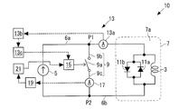
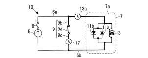
- FIG. 3A is a circuit diagram showing the superconducting magnet device 10 according to the embodiment of the present invention.
- the superconducting magnet device 10 may be a device that generates a magnetic field (for example, a static magnetic field) as a magnet for NMR or a magnet for MRI.
- the superconducting magnet device 10 may be a device that generates a magnetic field (for example, a static magnetic field) in another device (for example, a linear motor car or a particle accelerator).
- the superconducting magnet device 10 includes a superconducting coil 3, a power source 5, a cooling container 7, a protection device 9, a reverse diode 11 a, a forward diode 11 b, a detection device 13, and an operating device 15.
- a current detection unit 17 and a short-circuit current comparison unit 19 are provided.
- the superconducting coil 3 is provided for generating a magnetic field.
- Superconducting coil 3 is formed of a high-temperature superconducting wire.
- This high temperature superconducting wire is, for example, a tape-shaped wire.
- the aspect ratio (aspect ratio) of the cross section of the tape-shaped high-temperature superconducting wire (that is, the tape-shaped superconducting coil 3) is, for example, 5 to 10 or more.
- the “high-temperature superconducting wire” is a wire made of a superconductor material having a critical temperature Tc (transition temperature) of about 25 K or more in a non-magnetic field, and is an oxidation containing copper.
- Wires made of superconductor materials such as physical superconductors and iron-based superconductors are all high-temperature superconducting wires.
- a wire made of yttrium-based superconductor and bismuth-based superconductor is a high-temperature superconducting wire, and the one represented by the chemical formula YBa 2 Cu 3 O 7- ⁇ or the element Y in the formula is replaced with a rare earth element.
- a wire made of n O 4 + 2n + ⁇ is a high-temperature superconducting wire.
- high-temperature superconducting wires are those in which oxide nanoparticles such as zirconium and cisprosium are deposited on the wire to improve the critical current characteristics, or in which some are replaced with other elements.
- Wires in metallic superconductors consist of superconducting transition temperature as MgB 2 exceeds 25K is high-temperature superconducting wire.
- the transition temperature of the high temperature superconducting wire is higher than the transition temperature of the low temperature superconducting wire.
- the transition temperature of the high-temperature superconducting wire may be, for example, a value within a range of 25K or more and 153K or less (for example, a value of boiling point 77K or more of liquid nitrogen).
- the superconducting coil 3 may be formed by such a high-temperature superconducting wire.
- a superconducting coil formed of a high-temperature superconducting wire means a coil at least partially (partially or entirely) made of a high-temperature superconducting wire. To do.
- the power supply 5 generates a magnetic field in the superconducting coil 3 by supplying a current to the superconducting coil 3.
- the power source 5 is a constant current source that supplies a constant current to the superconducting coil 3.
- the value of the current that the power source 5 supplies to the superconducting coil 3 is, for example, in the range of 10 A or more and 10000 A or less, preferably 50 A or more and 2000 A or less.
- the positive electrode of the power source 5 and one end of the superconducting coil 3 are connected by a first current path 6a formed of a conductive material.
- the negative electrode of the power supply 5 and the other end of the superconducting coil 3 are connected by a second current path 6b formed of a conductive material.
- the power source 5 may be manufactured and sold separately from the superconducting magnet device 10 excluding the power source 5, and may be connected to the superconducting coil 3 when the superconducting magnet device 10 is installed.
- the cooling vessel 7 has an internal space 7a that is cooled below the transition temperature of the high-temperature superconducting wire forming the superconducting coil 3.
- Superconducting coil 3 is arranged in this internal space 7a.
- the cooling container 7 has the structure of FIG. 3B, FIG. 3C, or FIG. 3D, for example.
- the cooling container 7 has an inner container 7b and an outer container 7c as a double shell structure.
- the inner container 7b has the above-described internal space 7a, and a liquid refrigerant (that is, liquid nitrogen, liquid hydrogen, liquid argon, liquid helium, or other cryogenic refrigerant) is stored in the internal space 7a.
- a liquid refrigerant that is, liquid nitrogen, liquid hydrogen, liquid argon, liquid helium, or other cryogenic refrigerant
- Superconducting coil 3 is arranged in this refrigerant.
- a vacuum layer 7d that is a vacuum is formed between the inner container 7b and the outer container 7c.
- liquid refrigerant is poured into the internal space 7a regularly (for example, once every three months), but no problem occurs in the cooling container 7 even if a power failure occurs.
- the cooling container 7 has the same configuration as that of FIG. 3B, but a refrigerator 7e is attached to the cooling container 7.
- the refrigerator 7e recondenses the refrigerant in the internal space 7a.
- the refrigerator 7e since there is the refrigerator 7e, it is not necessary to periodically add a liquid refrigerant to the internal space 7a.
- the refrigerant in the internal space 7a runs out. (For example, within 7 days)
- the liquid refrigerant is added to the internal space 7a or power is supplied to the refrigerator 7e to restart the operation of the refrigerator 7e.
- a refrigerator 7 f is attached to the cooling container 7.
- the refrigerator 7f and the superconducting coil 3 are thermally connected by a heat conductor (metal plate or knitted wire) 7g.
- the cooling container 7 may be manufactured and sold separately from the superconducting magnet device 10 excluding the cooling container 7 and used with such a superconducting magnet device 10.
- the protective device 9 can form a short-circuit path that short-circuits both ends of the superconducting coil 3.
- the short circuit of the short circuit path may mean that the current decrease rate dI / dt is smaller than that in the case of the reverse diode 11a.
- the amount of heat generated by the electrical resistance of the short-circuit path that is, the amount of decrease in current due to this electrical resistance
- the reverse diode 11a It is smaller than the amount of heat generated at (ie, the amount of decrease in current due to this heat generation).
- the protection device 9 includes a switch 9a.
- One end of the switch 9 a is connected to one end of the superconducting coil 3, and the other end of the switch 9 a is connected to the other end of the superconducting coil 3.
- the protection device 9 includes a first conductive path 9b and a second conductive path 9c.
- the first conductive path 9b connects one end of the switch 9a and the intermediate point P1 of the first current path 6a
- the second conductive path 9c connects the other end of the switch 9a and the second current path 6b. Is connected to the middle point P2.
- Such a protective device 9 is provided outside the cooling container 7 in FIG. 3A, but may be provided in the internal space 7 a of the cooling container 7 together with the short-circuit current detection unit 17, and the element thereof is the cooling container. 7 may be distributed outside and inside.
- the protection device 9 is provided outside the power supply 5; however, the protection device 9 may be provided inside the power supply 5 (outside the cooling container 7), and the element of the protection device 9 is the power supply 5 It may be distributed outside and inside.
- the reverse diode 11 a is connected to the superconducting coil 3 in antiparallel. That is, the cathode of the reverse diode 11a is connected to one end of the superconducting coil 3 (positive electrode of the constant current source 5), and the anode of the reverse diode 11a is connected to the other end of the superconducting coil 3 (constant current source 5). Negative electrode).
- the anode of the forward diode 11b is connected to one end of the superconducting coil 3 (positive electrode of the constant current source 5), and the cathode of the forward diode 11b is connected to the other end of the superconducting coil 3 (constant current source). 5 negative electrode). Note that the forward diode 11b may be omitted.
- Detecting device 13 outputs a short-circuit signal to operating device 15 when detecting an abnormal state of superconducting magnet device 10 (for example, a state in which current supply from power supply 5 to superconducting coil 3 is abnormal).
- an abnormal state for example, a state in which current supply from power supply 5 to superconducting coil 3 is abnormal.
- this abnormal state is simply referred to as an abnormal state.
- such a detection device 13 is provided outside the cooling container 7, but may be provided in the internal space 7 a of the cooling container 7, and elements thereof may be provided outside and inside the cooling container 7. It may be provided in a distributed manner.
- the detection device 13 includes a supply current detection unit 13a, a supply current comparison unit 13b, and a short circuit signal output unit 13c.
- the supply current detection unit 13 a detects the magnitude of the current that the power source 5 supplies to the superconducting coil 3.
- the supply current detection unit 13a may be an ammeter.
- the ammeter 13a is provided in the first current path 6a in FIG. 3A, but may be provided in the second current path 6b.
- the supply current detection unit 13a only needs to detect the magnitude of the current supplied from the power supply 5 to the superconducting coil 3, and various configurations and arrangements of the supply current detection unit 13a can be employed.
- the supply current detection unit 13a measures the voltage at both ends of the superconducting coil 3, or the voltage at both ends of a resistor having a known electrical resistance value provided in the first current path 6a or the second current path 6b.
- the magnitude of the current supplied from the power source 5 to the superconducting coil 3 may be detected from the measured value.
- the supply current detection unit 13a may calculate the value (strength) of the magnetic field generated by the current flowing through the superconducting coil 3 or other part (for example, the first current path 6a or the second current path 6b), for example, DCCT or Hall
- the magnitude of the current supplied from the power source 5 to the superconducting coil 3 may be detected on the basis of the measured magnetic field value measured using an element or NMR phenomenon.
- the supply current comparison unit 13b determines whether the magnitude of the current detected by the supply current detection unit 13a does not satisfy the set condition.
- This setting condition is a condition that the magnitude of the current detected by the supply current detector 13a is larger than the threshold value, or a condition that the magnitude of this current is within the setting range.
- This threshold value may be zero, a value close to zero (for example, a value within a range of 0.1 A to 10 A), or a current detected by the supply current detection unit 13a during normal operation. May be a predetermined ratio (for example, an arbitrary ratio of 10% or less).
- the set range may be a range of the magnitude of the current detected by the supply current detection unit 13a at a normal time or a range close to this range.
- the short-circuit signal output unit 13c is determined by the supply current comparison unit 13b that the detection current value by the supply current detection unit 13a does not satisfy the above-described setting condition (that is, the detection current value is equal to or less than a threshold value, Alternatively, when the detected current value is smaller or larger than the set range), a short circuit signal is output to the actuator 15 as an abnormal condition has occurred.
- the actuating device 15 actuates the protective device 9 so that the protective device 9 forms a short circuit path by receiving the short circuit signal.
- the operation of the protection device 9 is an operation of closing the switch 9a. That is, the actuator 15 forms a short circuit path by closing the switch 9a.
- the actuating device 15 closes the switch 9a mechanically (by mechanical power) or magnetically (by electromagnetic force). Actuator 15 may be constituted so that switch 9a may be closed using gravity.
- the short circuit current detection unit 17 detects the magnitude of the current flowing through the short circuit path formed by the protection device 9.
- the short-circuit current detector 17 only needs to be able to detect the magnitude of the current flowing through the short-circuit path, and various configurations and arrangements of the short-circuit current detector 17 can be employed.
- the short-circuit current detection unit 17 may be provided in the second conductive path 9c as illustrated in FIG. 3A or may be provided in the first conductive path 9b.
- the short-circuit current detector 17 measures the voltage between the first conductive path 9b and the second conductive path 9c, and the measured value, the first conductive path 9b, and the second conductive path You may detect the magnitude
- the short-circuit current detection unit 17 determines the magnitude of the current flowing through the short-circuit path from the difference in current value at two locations other than the protective device 9 (the first conductive path 9b and the second conductive path 9c). May be detected. These two locations may be, for example, one location on the first current path 6a upstream from the midpoint P1 and one location on the first current path 6a downstream from the midpoint P1.
- the short circuit current detection part 17 may detect an electric current by the same principle as the supply current detection part 13a.
- the short-circuit current detection unit 17 measures the value of the magnetic field generated by the current flowing in the superconducting coil 3 or another location (for example, the short-circuit path), and based on this measurement value, the current flowing in the short-circuit path The size may be detected.
- the short-circuit current comparison unit 19 determines whether or not the magnitude of the current detected by the short-circuit current detection unit 17 is equal to or less than a set value (zero or a value close to zero) after recovery from the abnormal state.
- This set value is, for example, a value within a range of 0A or more and 1A or less. Preferably, this set value is a value in the range of 0 A or more and 0.2 A or less.
- the release signal output unit 21 outputs a short-circuit release signal to the actuator 15 when the result of determination by the short-circuit current comparison unit 19 is affirmative.
- the actuating device 15 releases the short-circuit path by the protection device 9 when receiving the short-circuit release signal or when receiving both the short-circuit release signal and the short-circuit release command.
- the short-circuit release command is output from the command output unit (not shown) to the actuator 15 after recovery from the abnormal state.
- This command output unit responds, for example, in response to resuming current supply from the power supply 5 to the superconducting coil 3, or in response to a person operating an appropriate operation unit (for example, a button) at the time of resumption.
- the short-circuit release command is output to the actuator 15.
- FIG. 4 is a flowchart showing a method for suppressing current decrease when the superconducting magnet device 10 described above is abnormal.
- FIG. 5A to FIG. 6B are explanatory diagrams of this current drop suppression method.
- a path through which a current flows is indicated by a bold line portion.
- 5A to 6B, illustration of the supply current comparison unit 13b, the short circuit signal output unit 13c, and the like is omitted.
- step S1 the superconducting magnet device 10 described above is installed. This state is shown in FIG. 5A. In FIG. 5A, no current has yet flowed.
- step S2 magnetic field generation by the superconducting magnet device 10 is started as follows.
- step S1 as described above, the superconducting coil 3 in the cooling container 7 is cooled, and the temperature of the internal space 7a of the cooling container 7 is made equal to or lower than the transition temperature of the high-temperature superconducting wire forming the superconducting coil 3. To do. Thereby, superconducting coil 3 will be in a superconducting state.
- step S2 with the switch 9a opened, for example, by closing the switch 8 (see FIGS. 5A to 5C), a current is supplied from the power source 5 to the superconducting coil 3 in the superconducting state. Thus, a magnetic field is generated in the superconducting coil 3.
- the inductance of the superconducting coil 3 (for example, a value in the range of 10H to 2000H, preferably a value in the range of 50H to 1000H) is large, a long time (half day) is set so that the superconducting coil 3 does not generate heat.
- a long time (half day) is set so that the superconducting coil 3 does not generate heat.
- the value of the current flowing through the superconducting coil 3 is changed from zero to the rated current value of the target value (preferably a value within a range of 50 A or more and 2000 A or less). Raise to. This state is shown in FIG. 5B. In FIG.
- the switch 8 is provided on the positive electrode side of the power supply 5. However, the switch 8 may be provided on the negative electrode side of the power supply 5 or on both the positive electrode side and the negative electrode side.
- step S2 the current of the rated current value flows through the superconducting coil 3 in the superconducting state, whereby the superconducting coil 3 generates a magnetic field. Thereafter, in this state, the process proceeds to step S3.
- step S3 when the superconducting coil 3 is generating a magnetic field, the detection device 13 determines whether or not the current supply from the power source 5 to the superconducting coil 3 is abnormal (abnormal state). When detecting the abnormal state, the detection device 13 proceeds to step S4. Otherwise, the determination in step S3 is repeated.
- an abnormal condition for example, there is a failure of the power supply 5.
- the switch 8 shown in FIGS. 5A to 6B is automatically opened, so that the power supply 5 is electrically disconnected from the superconducting coil 3.
- the state of FIG. 5B is shifted to the state of FIG. 5C.
- the current of the superconducting coil 3 flows through a closed circuit including the superconducting coil 3 and the reverse diode 11a (that is, a thick line circuit in this figure).
- the current value detected by the supply current detection unit 13a is significantly smaller than the above-described rated current value and does not satisfy the above-described setting condition. Therefore, this abnormal state is detected by the detection device 13.
- abnormal states include power outages and voltage drops.
- the power supply 5 cannot supply current to the superconducting coil 3.
- the state of FIG. 5B shifts to a state equivalent to FIG. 5C, and this abnormal state is detected by the detection device 13.
- the detection device 13 or the actuator 15 may be operated by an auxiliary power source, or the device that automatically switches the switch 9a to the closed state when the power source is lost. May be used.
- step S4 the detection device 13 outputs a short circuit signal to the operation device 15.
- the actuator 15 forms the short circuit path which short-circuits the both ends of the superconducting coil 3 by operating the protection device 9.
- FIG. 6A a closed circuit including the superconducting coil 3 and the protective device 9 (switch 9a) (that is, a thick line circuit in this figure) flows.
- the electric resistance value of the closed circuit is zero or greater than zero and 75 m ⁇ or less, and preferably zero or greater than zero and 30 m ⁇ or less.
- the resistance of this closed circuit is a value very close to zero. It may be.
- a low temperature superconducting wire for example, the internal space 7a of the cooling container 7 is cooled to a temperature lower than the transition temperature of the low temperature superconducting wire by, for example, liquid helium in step S2.
- the entire closed circuit is preferably arranged in the internal space 7a.
- the current decay rate when the protective device 9 is activated is preferably 1 ⁇ 2 or less of the current decay rate when the reverse diode 11a is activated (state of FIG. 5C). Is preferably 1/5 or less.
- the voltage generated between both ends of the protective device 9 is 0.75 V or less, preferably 0.3 V or less. desirable.
- step S3 the determination in the above-described step S3 is repeatedly performed. If an abnormal state is detected, step S4 described above is performed. Also in this case, after step S4, the process proceeds to step S5.
- step S5 a person performs recovery work such as repair or replacement of the power source 5. As a result, the abnormal state is resolved, and the process proceeds to step S6.
- step S6 the current supply from the normal power source 5 to the superconducting coil 3 is resumed. That is, for example, a current is supplied to the superconducting coil 3 from the repaired power supply 5 or a new power supply 5 in place of the failed power supply 5.
- step S6 may be performed when the person who performed step S5 pushes the button which operates the power supply 5.
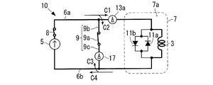
- FIG. 6B the value of the current supplied from the power source 5 to the superconducting coil 3 is gradually increased. This state is shown in FIG. 6B. In FIG. 6B, the current flows through a closed circuit including the superconducting coil 3 and the constant current source 5 (that is, a thick line circuit in this figure). As shown in FIG.
- the current from the constant current source 5 is divided into a current C1 flowing to the superconducting coil 3 and a current C2 flowing to the switch 9a, and the current C1 flowing through the superconducting coil 3 flows to the switch 9a. It is divided into a flowing current C3 and a current C4 flowing to the constant current source 5. Therefore, the current C2 and the current C3 cancel each other.
- the current (C3-C2) flowing through the switch 9a gradually decreases, and when the current C2 and the current C3 become the same size, the current flowing through the switch 9a becomes zero. Become.
- step S7 the short-circuit current comparison unit 19 detects the magnitude of the current flowing through the short-circuit path (switch 9a), and the short-circuit current comparison unit 19 determines whether or not the detected value is equal to or less than the above set value. .
- This set value is zero or a value close to zero (for example, a value greater than 0A and less than or equal to 5A). If the result of the determination in step S7 is affirmative, the process proceeds to step S8, and if not, the determination in step S7 is repeated.
- step S ⁇ b> 8 the release signal output unit 21 outputs the release signal to the operation device 15, so that the operation device 15 releases the short circuit path.
- the operating device 15 opens the switch 9a. This returns to the state of FIG. 5B.
- step S8 the current supplied from the constant current source 5 to the superconducting coil 3 is increased until the value of the current flowing through the superconducting coil 3 reaches the above-described rated current value. As a result, the process returns to step S3 while the current of the rated current value is flowing through the superconducting coil 3 in the superconducting state, and the processes in steps S3 to S8 described above are repeated.
- the superconducting coil 3 can continue to generate a magnetic field (not zero) for a while (for example, 6 hours to several days).
- the current flowing through the closed circuit is still not present when the restoration is completed. Big enough. Therefore, it is not necessary to restart the current supply from the power supply 5 after the restoration is completed and to increase the value of the current flowing through the superconducting coil 3 from zero, so that the current value is gradually increased to the target value. Takes less time. For example, even if the above abnormal condition occurs at midnight, even if recovery work is started in the morning and the recovery is completed in the morning of the day, the current value is gradually increased to the target value after recovery. This time is shortened.
- step S7 when it is detected in step S7 described above that the magnitude of the current flowing through the short circuit path is equal to or less than the set value, the actuator 15 releases the short circuit path. Thereby, when it returns to the original state, it can suppress that the electric current value of the superconducting coil 3 is fluctuate
- exciting the superconducting coil 3 that cannot perform the permanent current mode with the power supply means that the power supply 5 is left connected to the superconducting coil 3 for a longer time, and thus the probability of encountering a power supply failure or abnormality.
- the superconducting magnet device 10 there was only a superconducting magnet device that operates in a permanent current mode or repeats excitation and demagnetization in the short term. The problem that is not assumed in the low-temperature superconducting magnet can be solved by the superconducting magnet device 10.
- R is about the magnitude of the electric resistance value of the first current path 6a and the second current path 6b, and is set to 2.837 m ⁇ here.
- L is 74H and I is 50A.
- the decrease rate of the current flowing through the closed circuit X is 1.91 ⁇ 10 ⁇ 3 A / sec.
- liquid helium in the cooling vessel 7 (cryostat) is evaporated and ejected from the safety valve by one or both of heat generation in the reverse diode 11a and heat generation due to the hysteresis loss described above. .
- the protective device 9 causes a safe state of slow current decrease (that is, heat generation in the reverse diode 11a, and A state in which one or both of heat generation due to the above-described hysteresis loss of the superconducting coil 3 falls below the cooling capacity) can be performed.
- a safe state of slow current decrease that is, heat generation in the reverse diode 11a, and A state in which one or both of heat generation due to the above-described hysteresis loss of the superconducting coil 3 falls below the cooling capacity.
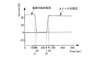
- FIG. 7A and 7B show changes in current and voltage when the power source 5 is disconnected from the superconducting coil 3 and then the protective device 9 is activated.
- the horizontal axis indicates time
- the vertical axis indicates the current value
- the broken line graph indicates the value of the current supplied from the power source 5 to the superconducting coil 3
- the solid line graph indicates the current flowing through the switch 9a. Indicates the value of.
- the switch 9a is closed. As a result, the value of the current flowing through the switch 9a increases rapidly.
- the current value decreases at a low rate of about 3 ⁇ 10 ⁇ 3 A / sec. Therefore, if the current supplied to the superconducting coil 3 before the time point t1 is set to 500 A or more, for example, from t4 Even after 6 hours, the current of 80% or more (400 A or more) still flows through the closed circuit X.
- the horizontal axis indicates time
- the vertical axis indicates the voltage value
- the solid line graph indicates the voltage across the switch 9a in the case of FIG. 7A.
- the power source 5 is disconnected from the superconducting coil 3 and the current flows through the reverse diode 11a, so that the potential difference between both ends of the switch 9a rapidly decreases (the potential difference From time t3 to time t4 ′, the potential difference of the switch 9a suddenly increases (the potential difference suddenly decreases) from time t3 to time t4 ′, and becomes almost zero. Yes.
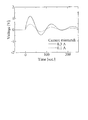
- FIG. 7B the horizontal axis indicates time
- the vertical axis indicates the voltage value
- the solid line graph indicates the voltage across the switch 9a in the case of FIG. 7A.
- Vc a potential difference between both ends of the superconducting coil 3
- L is an inductance of the superconducting coil 3
- dI / dt a time derivative of the current.
- FIG. 8 shows fluctuations in the value of the current flowing through the superconducting coil 3 when the original state is restored.
- a broken line indicates a voltage value (corresponding to a current value) flowing through the superconducting coil 3 when the short circuit path is released when the current flowing through the short circuit path is 0.1A.
- the solid line indicates the voltage value flowing through the superconducting coil 3 when the short circuit path is released when the current flowing through the short circuit path is 0.3 A.
- the time when the time on the horizontal axis is zero is the time when the short-circuit path is released.
- the reason why the current value of the short-circuit path in each case is low is to prevent the device from being damaged.
- a plurality (for example, five) of superconducting magnet devices 10 are mounted on a plurality of (for example, five) vehicles in a linear motor car. Accordingly, one power source 5 is mounted on each vehicle, but a standby power source is also mounted on the linear motor car.
- the control device central control management device
- the power source 5 is disconnected from the superconducting coil 3 by opening the switch 8.
- the control device electrically connects the normal standby power source as the replacement power source 5 to the superconducting coil 3 in step S ⁇ b> 6 described above, thereby superconducting coil.
- the current supply to 3 is resumed.
- control device takes in the measurement results or detection results of the abnormality of the power source 5 of each vehicle and various electrical quantities (current value, voltage value, etc.) of the electric circuit system including the superconducting magnet device 10 of each vehicle. Then, a series of control operations are executed by preinstalled software.
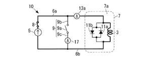
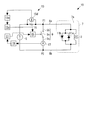
- FIG. 9 is a circuit diagram of the superconducting magnet device 10 according to the first modification of the present invention.
- the detection device 13 includes a voltage detection unit 13d, a voltage comparison unit 13e, and a short circuit signal output unit 13c as illustrated in FIG.
- the voltage detector 13d detects a voltage (potential difference) between two points on the current path (the first current path 6a and the second current path 6b) connecting the power source 5 and the superconducting coil 3. Between these two points, as shown in FIG. 8, an electric resistance 16 having a known electric resistance value may be provided.
- the voltage detector 13d has two voltage levels closer to the power source 5 than the connection point P1 between the first conductive path 9b and the first current path 6a as shown in FIG.
- the magnitude of the voltage at two points on the power source 5 side of the connection point P2 between the conductive path 9c and the second current path 6b is detected.
- the detection device 13 has two other points in the current path connecting the power source 5 and the superconducting coil 3 (for example, one point on the first conductive path 9b and one on the second conductive path 9c). Point) may be detected, and there are various patterns for the two points.
- the voltage comparison unit 13e determines whether the magnitude of the voltage detected by the voltage detection unit 13d does not satisfy the setting condition.
- This setting condition is a condition that the magnitude of the voltage detected by the voltage detector 13d is larger than the threshold value, or a condition that the magnitude of this voltage is within the setting range.
- This threshold value may be zero or a value close to zero, or a predetermined ratio of the magnitude of the voltage detected by the voltage detection unit 13d at normal time (for example, an arbitrary value of 10% or less) Ratio).
- the setting range may be a range of the magnitude of the voltage detected by the voltage detection unit 13d at normal time, or a range close to this range.
- the voltage comparison unit 13e determines that the short-circuit signal output unit 13c outputs a short-circuit signal to the actuator 15 because an abnormal state has occurred. Thereby, the operating device 15 operates the protective device 9 as described above.
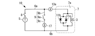
- FIG. 10A is a circuit diagram of a superconducting magnet device 10 according to Modification 2 of the present invention.
- the detection device 13 includes a power supply abnormality detection unit 13f, a stop operation unit 13g, and a short circuit signal output unit 13c as illustrated in FIG. 10A.
- the power supply abnormality detection unit 13f detects a power supply 5 abnormality. For example, the power supply abnormality detection unit 13f detects that the current value supplied by the power supply 5 is larger or smaller than the allowable range as an abnormality of the power supply 5. Alternatively, the power supply abnormality detection unit 13f detects that the abnormality (for example, the flow rate or the temperature) of the refrigerant (cooling water or cooling air) that cools the power supply 5 is outside the allowable range, as an abnormality of the power supply 5. In another example, the power supply abnormality detection unit 13f detects that the temperature of the power supply 5 is equal to or higher than the upper limit value as a power supply 5 abnormality. In yet another example, the power supply abnormality detecting unit 13f detects that the magnetic field in the vicinity of the power supply 5 is larger or smaller than the allowable range as an abnormality of the power supply 5.
- the abnormality for example, the flow rate or the temperature
- the refrigerant cooling water or cooling air
- the stop operation unit 13g stops the current supply from the power source 5 to the superconducting coil 3 when the power source abnormality detection unit 13f detects the abnormality of the power source 5. That is, the stop operation unit 13g electrically disconnects the power source 5 from the superconducting coil 3. For example, the stop operation unit 13g stops the current supply to the superconducting coil 3 by opening the switch 14 provided in the first current path 6a (or the second current path 6b).
- the short-circuit signal output unit 13c when the power supply abnormality detection unit 13f detects the abnormality of the power supply 5, the short-circuit signal output unit 13c outputs a short-circuit signal, so that the operating device 15 forms a short-circuit path as described above. That is, the short circuit signal output unit 13c is abnormal in response to the power supply abnormality detection unit 13f detecting the abnormality of the power supply 5 or in response to the stop operation unit 13g stopping the above-described current supply. A short circuit signal is output to the actuator 15 as the situation occurs.
- the stop operation unit 13g stops the current supply to the superconducting coil 3 by opening the switch 14 described above, Thereafter, the short circuit signal output unit 13c determines whether or not the operation of the protection device 9 is necessary, and outputs a short circuit signal to the operation device 15 when it is determined that this operation is necessary.
- the short-circuit signal output unit 13c operates the short-circuit signal by outputting a signal to that effect to the short-circuit signal output unit 13c. Output to the device 15.
- the abnormality of the cooling container 7 may be that the liquid level of the liquid refrigerant in the internal space 7a of the cooling container 7 is lower than the lower limit value, or may be other abnormality. .
- Such a detection device 13 may be incorporated in the power source 5.
- the stop operation unit 13g may not be provided.
- the short circuit signal output unit 13c outputs a short circuit signal in response to the power supply abnormality detection unit 13f detecting the abnormality of the power source 5.
- the power supply 5 and the superconducting coil 3 do not necessarily have to be separated from each other.
- the power source abnormality detection unit 13f detects the abnormality of the power source 5 and outputs a short circuit signal.
- FIG. 10B shows the configuration of the superconducting magnet device 10 when the safety device 18 is provided.
- the safety device 18 includes, for example, a power supply monitoring unit 18a, an operation unit 18b, and a switch 18c.
- the power monitoring unit 18a detects an abnormality in the power source 5
- the power monitoring unit 18a outputs an operation signal to the operation unit 18b.
- the operating unit 18b operates to open the switch 18c by receiving an operating signal from the operating unit 18b.
- the power supply monitoring unit 18a detects that the current value supplied by the power supply 5 is larger or smaller than an allowable range (for example, an allowable range wider than the allowable range used by the power supply abnormality detection unit 13f) as an abnormality of the power supply 5. To do.
- the power supply monitoring unit 18a has an allowable range in which an abnormality (for example, a flow rate or a temperature) of a refrigerant (cooling water or cooling air) for cooling the power supply 5 is larger than an allowable range (for example, the allowable range used by the power supply abnormality detection unit 13f). ) It is detected as an abnormality of the power supply 5 that it has gone outside.
- the power supply monitoring unit 18a detects that the temperature of the power supply 5 has reached an upper limit value (for example, an upper limit value higher than the upper limit value used by the power supply abnormality detection unit 13f) as an abnormality of the power supply 5. .
- the power supply monitoring unit 18a may be omitted, and the operation unit 18b may operate to close the switch 18c in response to the power supply abnormality detection unit 13f detecting the abnormality of the power supply 5.
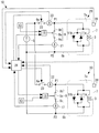
- Superconducting coil 3 may be used in combination with other coils.
- a low temperature superconducting coil 31 formed of a low temperature superconducting wire is disposed outside the superconducting coil 3 in the internal space 7 a of the cooling container 7.
- the superconducting coil 3 is indicated by a bold line.
- the superconducting coil 3 and the low-temperature superconducting coil 31 are arranged coaxially in the internal space 7a.
- a circuit for supplying current to the low-temperature superconducting coil 31 ie, the diode 33, the power source 35, and the permanent switch 37 in FIG. 11
- the circuit for supplying current to the superconducting coil 3 are independent of each other.
- the internal space 7a is cooled below the transition temperature of the low-temperature superconducting wire of the low-temperature superconducting coil 31 by, for example, liquid helium.
- the configuration and function of the low temperature superconducting coil 31, diode 33, power source 35, permanent switch 37, and heater 39 are the same as those of the low temperature superconducting coil 31, diode 33, power source 35, permanent It may be the same as the switch 37 and the heater 39.
- the superconducting coil 31 can continue to generate a magnetic field while the power source 35 is disconnected from the low temperature superconducting coil 31. It is.
- the power source 35 may be connected to the low temperature superconducting coil 31.
- the reverse diode 11a described above may be omitted.
- the actuator 15 closes the switch 9a before the current starts to flow through the reverse diode 11a. If possible, the reverse diode 11a may be omitted.
- the protection device 9 may be manually operated to form the above-described short-circuit path.
- an operation unit for example, a button or a lever
- the switch 9a may be closed or opened by operating the operation unit by a person.
- the switch 9a is closed by manual operation instead of steps S3 to S5 after step S2. Maintenance is performed in this state. After the maintenance is completed, steps S6 to S8 are performed.
- the superconducting coil 3 can be maintained in the superconducting state until the liquid refrigerant in the cooling container 7b is exhausted.
- the detection device 13 may be omitted, but the detection device 13 may also be provided and the protection device 9 may be operated by the detection device 13 and the operation device 15.
- a low temperature superconducting coil formed of a low temperature superconducting wire may be connected in series to the superconducting coil 3 described above.
- a low-temperature superconducting coil is disposed together with the superconducting coil 3 in the internal space 7a of the cooling vessel 7, and the internal space 7a is cooled to a temperature lower than the transition temperature of the low-temperature superconducting coil.
- the low temperature superconducting coil is disposed in another cooling container that is cooled to a temperature lower than the transition temperature of the low temperature superconducting coil.
- one or a plurality of superconducting coils formed of high-temperature superconducting wires may be connected to the superconducting coil 3 in series.
- the protection device 9 short-circuits both ends of a part or the whole (superconducting coil 3) of these superconducting coils constituting the superconducting magnet device 10.
- the superconducting coil 3 may be formed by connecting a plurality of superconducting coils formed of high-temperature superconducting wires in series with each other.
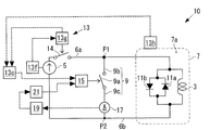
- FIG. 12 shows a configuration of a superconducting magnet device 10 according to the modified example 7.
- the superconducting magnet device 10 has a plurality of magnetic field generation devices 20.
- the number of the magnetic field generation devices 20 included in the superconducting magnet device 10 is two in the figure, but may be any number of three or more.
- Each magnetic field generation device 20 includes the superconducting coil 3, the cooling vessel 7, the protection device 9, the reverse diode 11a, and the forward diode 11b described above.
- the superconducting magnet device 10 has one power source 5 shared by a plurality of magnetic field generation devices 20.
- the superconducting magnet device 10 is provided in each magnetic field generation device 20, and in the magnetic field generation device 20, a short-circuit current detection for detecting a value of a current flowing through a closed circuit including the superconducting coil 3 and the closed switch 9a.
- the unit 17 is provided.
- the value of the detected current means the magnitude (hereinafter the same).
- the superconducting magnet device 10 is provided in each magnetic field generating device 20 and detects the value of the current flowing through the superconducting coil 3 or the value of the magnetic field generated by the superconducting coil 3 with the switch 9a closed.
- a coil state detector 17 or 28 is provided. When this coil state detection unit detects the value of the current flowing through the superconducting coil 3, this coil state detection unit may be the short-circuit current detection unit 17, but is not limited thereto.
- the coil state detection unit detects the value of the magnetic field generated by the superconducting coil 3, the coil state detection unit is a magnetic field detection unit 28 provided separately from the short-circuit current detection unit 17.
- the value of the current or magnetic field detected by the coil state detection unit 17 or 28 means the magnitude (the same applies hereinafter).
- the superconducting magnet device 10 is provided in each magnetic field generation device 20, and the magnetic field generation device 20 from the power source 5 (that is, the connection point P1 between the first current path 6a and the first conductive path 9b in FIG. 12).
- a supply current detector 22 is provided for detecting the value of the current supplied to.
- the value of the detected current means the magnitude (hereinafter the same).
- the supply current detector 22 is upstream of the connection point P1 in the first current path 6a, or downstream of the connection point P2 of the second current path 6b and the second conductive path 9c in the second current path 6b. Provided on the side.
- the current detection unit 13 a may function as the supply current detection unit 22.
- various devices for example, a device using a measured value of a magnetic field
- the superconducting magnet device 10 is provided in each magnetic field generation device 20, a closed position where a current is supplied from the power source 5 to the magnetic field generation device 20 (connection point P ⁇ b> 1), and the magnetic field generation device 20 ( A current supply switch 23 is provided which is operated between the open position where the connection point P1) is disconnected.
- the superconducting magnet device 10 includes a control device 24.
- the control device 24 controls the operating device 15 based on the detected current value or the detected magnetic field value by the supply current detection unit 22, the coil state detection unit 17 or 28, or the short-circuit current detection unit 17, thereby providing a current supply switch.
- the positions of the switch 23 and the switch 9a are switched between a closed position and an open position. That is, in each magnetic field generation device 20, the control device 24 sets the detected current value or the detected magnetic field value by the coil state detection unit 17 or 28 to the reference value (positive value) in a state where the switch 9 a of the protection device 9 is closed. When the following occurs, the current supply switch 23 of the magnetic field generation device 20 is moved to the closed position.
- the control device 24 switches the protection device 9 when the current value detected by the short-circuit current detection unit 17 becomes equal to or less than the above set value in the process of increasing the current supplied from the power source 5 to the magnetic field generation device 20.
- the protection device 9 is operated.
- the current supply switch 23 is operated. Move to the open position.
- connection point P1 The value of the current passed from the power supply 5 to the magnetic field generator 20 (connection point P1) is gradually reduced.
- the control device 24 controls the power supply 5 so as to gradually decrease the current value.
- each magnetic field generation device 20 By performing the above (1) to (5) for each magnetic field generation device 20, in each magnetic field generation device 20, the current supply switch 23 is in the open position, the switch 9a is in the closed position, and superconductivity
- the above-mentioned rated current value (or a current larger than the reference value) is flowing in a closed circuit (corresponding to the thick line circuit in FIG. 6A) including the coil 3 and the switch 9a (or by the coil state detection unit 28).
- the detected magnetic field value becomes larger than the reference value).
- This state is set as a reference state. From this reference state, the superconducting magnet device 10 operates in the following order (6) to (11).
- the reference value is smaller than the rated current value.
- the control device 24 controls the magnetic field generation device.
- the 20 current supply switches 23 are operated to the closed position.
- the following (7) to (11) are performed on the magnetic field generation apparatus 20.
- a current is supplied from the power source 5 to the superconducting coil 3.
- the power source 5 gradually increases the value of the current.
- the control device 24 controls the power supply 5 so as to gradually increase the value of the current.
- the switch 9a is in the closed position.
- the power supply 5 gradually increases the value of the current (for example, the control device 24 controls the power supply 5 so as to gradually increase the value of the current), thereby detecting the supply current
- the control device 24 operates the switch 9a to the closed position.
- the control device 24 controls the power supply 5 so as to gradually decrease the current value.
- Such a superconducting magnet device 10 can be provided in a linear motor car. That is, the superconducting magnet device 10 is provided in a linear motor car (running vehicle), and the magnetic field generated by the plurality of superconducting coils 3 of the superconducting magnet device 10 is used for propulsion and levitation of the linear motor car.
- the above operations (6) to (11) may be performed while the linear motor car is traveling.
- a plurality of such superconducting magnet devices 10 may be provided in a linear motor car.
- the protection device 9 and the short-circuit current detection unit 17 are provided outside the cooling container 7 in FIG. 12, but may be provided in the internal space 7 a of the cooling container 7.
- the number of power supplies 5 used can be suppressed. Further, in each magnetic field generating device 20, when the magnitude of the current flowing through the superconducting coil 3 or the magnitude of the magnetic field generated by the superconducting coil 3 becomes equal to or less than the reference value, the current is supplied from the power source 5 to the magnetic field generating device 20. Therefore, the use frequency of the power source 5 can be suppressed. Furthermore, even when the power source 5 is not connected to the superconducting coil 3, the current decrease can be suppressed or reduced.
- each magnetic field generation device 20 is provided with the detection device 13 and the operation device 15 described above. Therefore, when an abnormal state occurs during the operation (2) or (9) described above, the protection device 9 forms the above-described short-circuit path by the inspection device 13 and the operation device 15. Therefore, the protection function of the protection device 9 can be utilized. Also in the modified example 7, the functions of the short-circuit current comparison unit 19 and the release signal output unit 21 described above are incorporated in the control device 24. Therefore, according to (8) above, the opening operation control of the switch 9a based on the short-circuit current detection function of the short-circuit current detection unit 17 can be executed.
- the power source 5 in this case is not provided in the linear motor car (that is, the traveling vehicle), but is provided in the vehicle stop position (stationary structure), and the superconducting magnet device 10 excluding the power source 5 is provided in the linear motor car.
- the magnetic field generated by the superconducting coil 3 of the superconducting magnet device 10 is used for propulsion and levitation of the linear motor car.
- the linear motor car can suppress a decrease in the current flowing through the superconducting coil 3.
- the protection device 9 has a function of protecting the circulating current in the sense of suppressing a decrease in circulating current.
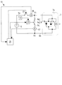
- the superconducting magnet device 10 includes a supply current detection unit 26, a current supply switch 27, and a control device 25.
- the supply current detection unit 26 determines the value (magnitude) of the current supplied from the power supply 5 to the superconducting coil 3 (that is, the connection point P1 between the first current path 6a and the first conductive path 9b in FIG. 13). To detect.
- the configuration and arrangement of the supply current detection unit 26 are the same as those of the supply current detection unit 22 of the seventh modification.
- the current supply switch 27 operates between a closed position where current is supplied from the power source 5 to the superconducting coil 3 (connection point P1) and an open position where the superconducting coil 3 (connection point P1) is disconnected from the power source 5. Be made.
- the configuration and arrangement of the current supply switch 27 are the same as those of the current supply switch 23 of the seventh modification.
- the control device 25 switches the positions of the current supply switch 27 and the switch 9a between the closed position and the open position by controlling the operating device 15 based on the current value detected by the supply current detector 26.
- connection point P1 the value of the current flowing from the power source 5 to the superconducting coil 3 (connection point P1) is gradually reduced.
- the control device 25 controls the power supply 5 so as to gradually decrease the current value.
- (G) Current is supplied from the power source 5 to the superconducting coil 3 with the switch 9a in the closed position.
- the current value is gradually increased.
- the control device 25 controls the power supply 5 so as to gradually increase the value of the current.
- the power supply 5 gradually increases the value of the current (for example, the control device 25 controls the power supply 5 so as to gradually increase the value of the current), thereby detecting the supply current
- the control device 25 operates the switch 9a to the closed position.
- connection point P1 the value of the current flowing from the power source 5 to the superconducting coil 3 (connection point P1) is gradually reduced.
- the control device 25 controls the power supply 5 so as to gradually decrease the current value.
- the protective device 9 and the short-circuit current detection unit 17 are provided outside the cooling container 7 in FIG. 13, but may be provided in the internal space 7 a of the cooling container 7.
- the detection device 13 and the operation device 15 are provided in the superconducting magnet device 10 as described above. Therefore, when an abnormal state occurs during the operation (b) or (i) described above, the protection device 9 forms the above-described short-circuit path by the inspection device 13 and the operation device 15. Therefore, the protection function of the protection device 9 can be utilized. Also in the modified example 8, in FIG. 13, the functions of the short-circuit current comparison unit 19 and the release signal output unit 21 are incorporated in the control device 25. Therefore, the opening operation control of the switch 9a based on the short-circuit current detection function of the short-circuit current detection unit 17 can be executed by the above (h).
- 3 superconducting coil 5 power source (constant current source), 6a first current path, 6b second current path, 7 cooling container, 7a inner space, 7b inner container, 7c outer container, 7d vacuum layer, 7e refrigerator, 7f Refrigerator, 8 switch, 9 protection device, 9a switch, 9b 1st conductive path, 9c 2nd conductive path, 10 superconducting magnet device, 11a reverse diode, 11b forward diode, 13 detector, 13a supply current Detection part (ammeter), 13b Supply current comparison part, 13c Short circuit signal output part, 13d Voltage detection part, 13e Voltage comparison part, 13f Power supply abnormality detection part, 13g Stop operation part, 14 switch, 15 actuator, 16 electrical resistance 17 Short circuit current detection unit (coil state detection unit) 18 Safety device 18a Power supply monitoring unit 18b Actuation unit 8c switch, 19 short circuit current comparison unit, 20 magnetic field generation device, 21 release signal output unit, 22 supply current detection unit, 23 current supply switch, 24 control device, 25 control device, 26 supply current detection unit
Landscapes
- Engineering & Computer Science (AREA)
- Power Engineering (AREA)
- Containers, Films, And Cooling For Superconductive Devices (AREA)
- Magnetic Resonance Imaging Apparatus (AREA)
Abstract
A superconducting magnet device 10 is installed which is provided with a superconducting coil 3 formed of a high temperature superconducting wire; a power supply 5 which supplies a current to the superconducting coil 3; and a protection device 9 capable of forming a short-circuit path for short-circuiting both ends of the superconducting coil 3 to each other. Then, the current from the power supply 5 is caused to flow to the superconducting coil 3 in a superconducting state so as to generate a magnetic field in the superconducting coil 3. Thereafter, if abnormality is detected in the superconducting magnet device 10, or when the power supply 5 and the superconducting coil 3 are to be separated from each other, the short-circuit path is formed by the protection device 9.
Description
本発明は、高温超伝導線で形成された超伝導コイルと、超伝導コイルに電流を供給することにより磁場を発生させるための超伝導コイルとを備える超伝導磁石装置に関する。また、本発明は、超伝導磁石装置の異常時の電流低下抑制方法に関する。
The present invention relates to a superconducting magnet device comprising a superconducting coil formed of a high-temperature superconducting wire and a superconducting coil for generating a magnetic field by supplying a current to the superconducting coil. The present invention also relates to a method for suppressing a decrease in current when the superconducting magnet device is abnormal.
超伝導磁石装置は、大電流を流すことができる超伝導コイルを備えていることにより、強力な磁場を発生させることができる。このような超伝導磁石装置は、NMR(nuclear magnetic resonance)用の磁石や、MRI(magnetic resonance imaging)用の磁石として用いることができる。また、超伝導磁石装置を、他の用途(例えば、リニアモーターカー)でも用いることもできる。なお、超伝導は超電導と表記されてもよいが、本願では超伝導と表記する。
The superconducting magnet device can generate a strong magnetic field by including a superconducting coil capable of flowing a large current. Such a superconducting magnet device can be used as a magnet for NMR (nuclear magnetic resonance) or a magnet for MRI (magnetic resonance imaging). The superconducting magnet device can also be used in other applications (for example, a linear motor car). Although superconductivity may be expressed as superconductivity, it is expressed as superconductivity in the present application.
従来において、超伝導磁石装置は、低温超伝導線で形成された超伝導コイルを用いて、例えばNMR用磁石として実用化されている。
Conventionally, a superconducting magnet device has been put into practical use, for example, as an NMR magnet, using a superconducting coil formed of a low-temperature superconducting wire.
図1A~図1Cは、実用化されている超伝導磁石装置の回路図である。超伝導磁石装置は、低温超伝導線で形成された超伝導コイル31と、超伝導コイル31に並列に接続されたダイオード33と、超伝導コイル31に電流を供給する電源35と、永久電流スイッチ37と、加温用のヒーター39とを有する。永久電流スイッチ37は、低温超伝導線により形成されている。この低温超伝導線37は、後述するようにスイッチとして機能するので、図1A~図1Cでは、スイッチの記号で表わしている。また、超伝導コイル31と永久電流スイッチ37とを含むがダイオード33を含まない閉回路(後述の図1Cの太線の回路)は、永久電流モードを実現するために、低温超伝導線により形成されている。以下、この閉回路を超伝導閉回路という。
1A to 1C are circuit diagrams of a superconducting magnet device in practical use. The superconducting magnet device includes a superconducting coil 31 formed of a low-temperature superconducting wire, a diode 33 connected in parallel to the superconducting coil 31, a power supply 35 for supplying current to the superconducting coil 31, and a permanent current switch. 37 and a heater 39 for heating. The permanent current switch 37 is formed of a low temperature superconducting wire. Since this low-temperature superconducting wire 37 functions as a switch as will be described later, in FIG. 1A to FIG. 1C, it is represented by a switch symbol. Further, a closed circuit (a thick line circuit in FIG. 1C described later) including the superconducting coil 31 and the permanent current switch 37 but not including the diode 33 is formed by a low-temperature superconducting wire in order to realize the permanent current mode. ing. Hereinafter, this closed circuit is referred to as a superconducting closed circuit.
図1A~図1Cの超伝導磁石装置は、以下の手順により、電流が減衰しない永久電流モードで磁場を発生させることができる。
The superconducting magnet apparatus of FIGS. 1A to 1C can generate a magnetic field in a permanent current mode in which current does not decay by the following procedure.
まず、超伝導コイル31、ダイオード33、および永久電流スイッチ37を、冷却容器38内の液体ヘリウム中に配置する。これにより、上述の超伝導閉回路は、転移温度以下に冷却される。転移温度は、常伝導状態から超伝導状態に移り変わる温度である(以下、同様)。したがって、超伝導閉回路は、電気抵抗がゼロの超伝導状態になる。
First, the superconducting coil 31, the diode 33, and the permanent current switch 37 are placed in liquid helium in the cooling vessel 38. Thereby, the above-mentioned superconducting closed circuit is cooled below the transition temperature. The transition temperature is a temperature at which the transition from the normal state to the superconducting state (hereinafter the same). Therefore, the superconducting closed circuit is in a superconducting state with zero electrical resistance.
次に、永久電流スイッチ37を、ヒーター39で、上述の転移温度より高い温度に加温する。これにより、永久電流スイッチ37(超伝導線)は常伝導状態に転移し、超伝導閉回路の輪が切れた状態になる。言い換えると、永久電流スイッチ37がオフになる(図1Aの状態)。
Next, the permanent current switch 37 is heated by the heater 39 to a temperature higher than the above transition temperature. As a result, the permanent current switch 37 (superconducting wire) transitions to the normal conducting state, and the superconducting closed circuit is disconnected. In other words, the permanent current switch 37 is turned off (the state shown in FIG. 1A).
その後、電源35から超伝導コイル31へ電流を流すと、電流は、図1Bのように、この図の太線の経路を流れる。この時、永久電流スイッチ37は、常伝導状態にあるので、永久電流スイッチ37には電流がほとんど流れない。
Thereafter, when a current is passed from the power source 35 to the superconducting coil 31, the current flows through the thick line in this figure as shown in FIG. 1B. At this time, since the permanent current switch 37 is in a normal conduction state, almost no current flows through the permanent current switch 37.
この状態で、電源35からの電流を増やす。この電流値が定格電流値まで増えたら、ヒーター39による加温を止める。これにより、永久電流スイッチ37(超伝導線)は、液体ヘリウムにより再び冷やされて超伝導状態に転移する。
In this state, increase the current from the power source 35. When this current value increases to the rated current value, heating by the heater 39 is stopped. As a result, the permanent current switch 37 (superconducting wire) is cooled again by liquid helium and transitions to the superconducting state.
その後、電源35からの電流を減らしていくと、永久電流スイッチ37を流れる電流が増えていく。電源35からの電流がゼロになると、永久電流スイッチ37から超伝導コイル31へ流れる電流の値は、上述の定格電流値となる。この電流は、減衰することなく、上述の超伝導閉回路を循環するようになる。すなわち、電流は、図1Cのように、この図の太線の経路を流れる。この時、超伝導磁石装置は、電源なしで超伝導コイル31が磁場を発生させている永久電流モードになっている。
Thereafter, when the current from the power source 35 is reduced, the current flowing through the permanent current switch 37 increases. When the current from the power source 35 becomes zero, the value of the current flowing from the permanent current switch 37 to the superconducting coil 31 becomes the above-described rated current value. This current circulates in the superconducting closed circuit described above without being attenuated. That is, the current flows through the thick line in this figure as shown in FIG. 1C. At this time, the superconducting magnet device is in a permanent current mode in which the superconducting coil 31 generates a magnetic field without a power source.
上述のように永久電流モードで磁場を発生させる超伝導磁石装置は、例えば下記の特許文献1に記載されている。
A superconducting magnet device that generates a magnetic field in the permanent current mode as described above is described in, for example, Patent Document 1 below.
(高温超伝導線の利点)
図1A~図1Cの超伝導磁石装置では低温超伝導線を用いていたが、高温超伝導線を用いた超伝導磁石装置の実現が望まれる。高温超伝導線では、主に以下の2つの利点があるからである。第1に、高温超伝導線の転移温度は、例えば液体窒素の沸点(77K)以上であり、低温超伝導線の転移温度よりも高い。第2に、高い磁場中においても、高温超伝導線に大きな電流を流すことができる。 (Advantages of high-temperature superconducting wire)
Although the superconducting magnet device of FIGS. 1A to 1C uses a low-temperature superconducting wire, it is desired to realize a superconducting magnet device using a high-temperature superconducting wire. This is because the high-temperature superconducting wire mainly has the following two advantages. First, the transition temperature of the high-temperature superconducting wire is, for example, not less than the boiling point (77K) of liquid nitrogen and higher than the transition temperature of the low-temperature superconducting wire. Second, a large current can be passed through the high-temperature superconducting wire even in a high magnetic field.
したがって、液体ヘリウムを用いなくても、例えば液体窒素や小型冷凍機などにより、高温超伝導線で形成した超伝導コイルを超伝導状態にすることができる。また、高温超伝導線の超伝導コイルは、高い磁場中でも(周囲から発生する磁場が高い場合でも)、高温超伝導線の超伝導コイルに大電流を流すことにより強力な磁場が得られる。さらに、高温超伝導線の超伝導コイルを有する超伝導磁石装置では、低温超伝導線を用いた場合よりも小型の構成で、同じ強さの磁場を発生させることができる。
Therefore, even if liquid helium is not used, a superconducting coil formed of a high-temperature superconducting wire can be brought into a superconducting state by using, for example, liquid nitrogen or a small refrigerator. In addition, the superconducting coil of the high-temperature superconducting wire can obtain a strong magnetic field by flowing a large current through the superconducting coil of the high-temperature superconducting wire even in a high magnetic field (even when the magnetic field generated from the surroundings is high). Furthermore, a superconducting magnet device having a superconducting coil of a high-temperature superconducting wire can generate a magnetic field having the same strength with a smaller configuration than when a low-temperature superconducting wire is used.
(高温超伝導線を用いた装置の構成)
しかし、高温超伝導線を用いた超伝導磁石装置は、永久電流モードで磁場を発生させることができない。高温超伝導線同士を、もしくは高温超伝導線と低温超伝導線とをゼロの電気抵抗で接続することができないからである。すなわち、図1Cの超伝導閉回路の電気抵抗はゼロであるが、高温超伝導線を用いた場合には電気抵抗ゼロの閉回路を実現できない。 (Configuration of equipment using high-temperature superconducting wire)
However, a superconducting magnet device using a high-temperature superconducting wire cannot generate a magnetic field in the permanent current mode. This is because high temperature superconducting wires or high temperature superconducting wires and low temperature superconducting wires cannot be connected with zero electrical resistance. That is, the electrical resistance of the superconducting closed circuit of FIG. 1C is zero, but when a high-temperature superconducting wire is used, a closed circuit of zero electrical resistance cannot be realized.
そのため、高温超伝導線を用いた超伝導磁石装置の構成として、永久電流スイッチを使用しない図2の構成が考えられる。
図2において、超伝導磁石装置は、高温超伝導線で形成された超伝導コイル41と、超伝導コイル41に並列に接続されたダイオード43と、超伝導コイル41に電流を供給する電源45とを有する。超伝導コイル41およびダイオード43を含む回路部分は、例えば冷却容器47内の冷媒(すなわち、液体窒素、液体水素、液体アルゴン、液体ヘリウム、または他の極低温冷媒)や小型冷凍機などにより、高温超伝導線の転移温度以下に冷却される。 Therefore, as a configuration of a superconducting magnet device using a high-temperature superconducting wire, the configuration of FIG. 2 that does not use a permanent current switch is conceivable.
In FIG. 2, the superconducting magnet device includes asuperconducting coil 41 formed of a high-temperature superconducting wire, a diode 43 connected in parallel to the superconducting coil 41, and a power supply 45 for supplying current to the superconducting coil 41. Have The circuit portion including the superconducting coil 41 and the diode 43 is heated at a high temperature by, for example, a refrigerant (that is, liquid nitrogen, liquid hydrogen, liquid argon, liquid helium, or other cryogenic refrigerant) in the cooling container 47 or a small refrigerator. It is cooled below the transition temperature of the superconducting wire.
図2において、超伝導磁石装置は、高温超伝導線で形成された超伝導コイル41と、超伝導コイル41に並列に接続されたダイオード43と、超伝導コイル41に電流を供給する電源45とを有する。超伝導コイル41およびダイオード43を含む回路部分は、例えば冷却容器47内の冷媒(すなわち、液体窒素、液体水素、液体アルゴン、液体ヘリウム、または他の極低温冷媒)や小型冷凍機などにより、高温超伝導線の転移温度以下に冷却される。 Therefore, as a configuration of a superconducting magnet device using a high-temperature superconducting wire, the configuration of FIG. 2 that does not use a permanent current switch is conceivable.
In FIG. 2, the superconducting magnet device includes a
(高温超伝導線を用いた装置の磁場発生方法)
図2の場合、以下の手順により、超伝導磁石装置に磁場を発生させることが考えられる。
まず、超伝導コイル41およびダイオード43を、上述の冷媒や小型冷凍機などにより、高温超伝導線の転移温度以下に冷却する。
次に、電源45からの電流を、例えば50A~2000Aの大電流まで増やす。
その後、電源45を超伝導コイル41に接続した状態を維持することにより、超伝導コイル41を流れる電流を一定に維持する。電源45の接続を維持するのは、高温超伝導線を用いた場合には電気抵抗ゼロの超伝導閉回路を実現できないからである。 (Method for generating magnetic field of equipment using high temperature superconducting wire)
In the case of FIG. 2, it is conceivable to generate a magnetic field in the superconducting magnet device by the following procedure.
First, thesuperconducting coil 41 and the diode 43 are cooled below the transition temperature of the high-temperature superconducting wire by the above-described refrigerant or small refrigerator.
Next, the current from thepower supply 45 is increased to a large current of 50 A to 2000 A, for example.
Thereafter, by maintaining the state where thepower supply 45 is connected to the superconducting coil 41, the current flowing through the superconducting coil 41 is maintained constant. The connection of the power supply 45 is maintained because a superconducting closed circuit with zero electrical resistance cannot be realized when a high-temperature superconducting wire is used.
図2の場合、以下の手順により、超伝導磁石装置に磁場を発生させることが考えられる。
まず、超伝導コイル41およびダイオード43を、上述の冷媒や小型冷凍機などにより、高温超伝導線の転移温度以下に冷却する。
次に、電源45からの電流を、例えば50A~2000Aの大電流まで増やす。
その後、電源45を超伝導コイル41に接続した状態を維持することにより、超伝導コイル41を流れる電流を一定に維持する。電源45の接続を維持するのは、高温超伝導線を用いた場合には電気抵抗ゼロの超伝導閉回路を実現できないからである。 (Method for generating magnetic field of equipment using high temperature superconducting wire)
In the case of FIG. 2, it is conceivable to generate a magnetic field in the superconducting magnet device by the following procedure.
First, the
Next, the current from the
Thereafter, by maintaining the state where the
(高温超伝導線を用いた装置の課題)
図2の場合において、例えば次の(1)~(3)のように、異常が起こると、電源45と超伝導コイル41とが互いに電気的に切り離されることが想定される。
(1)停電または瞬低(瞬時電圧低下)が起こると、電源45からの電流供給が停止され、電源45が超伝導コイル41から切り離された状態になる。
(2)電源45が供給する電流値が許容範囲よりも大きく又は小さくなったことや、電源45を冷却する冷却水の流れが停止したことなどの故障がセンサにより検知された場合に、電源45と超伝導コイル41とを接続するスイッチ(図示せず)がオフにされることにより、両者が互いに切り離される。
(3)他の理由により(例えばメンテナンスを行うために)、電源45と超伝導コイル41とを接続するスイッチがオフにされることにより、両者が互いに切り離される。 (Issues with equipment using high-temperature superconducting wires)
In the case of FIG. 2, it is assumed that thepower supply 45 and the superconducting coil 41 are electrically disconnected from each other when an abnormality occurs, for example, as in the following (1) to (3).
(1) When a power failure or instantaneous drop (instantaneous voltage drop) occurs, the current supply from thepower supply 45 is stopped, and the power supply 45 is disconnected from the superconducting coil 41.
(2) When a sensor detects a failure such as that the current value supplied by thepower supply 45 is larger or smaller than the allowable range or the flow of cooling water for cooling the power supply 45 is stopped, the power supply 45 And a switch (not shown) connecting the superconducting coil 41 are turned off, so that they are separated from each other.
(3) For other reasons (for example, for maintenance), the switch connecting thepower supply 45 and the superconducting coil 41 is turned off, so that they are disconnected from each other.
図2の場合において、例えば次の(1)~(3)のように、異常が起こると、電源45と超伝導コイル41とが互いに電気的に切り離されることが想定される。
(1)停電または瞬低(瞬時電圧低下)が起こると、電源45からの電流供給が停止され、電源45が超伝導コイル41から切り離された状態になる。
(2)電源45が供給する電流値が許容範囲よりも大きく又は小さくなったことや、電源45を冷却する冷却水の流れが停止したことなどの故障がセンサにより検知された場合に、電源45と超伝導コイル41とを接続するスイッチ(図示せず)がオフにされることにより、両者が互いに切り離される。
(3)他の理由により(例えばメンテナンスを行うために)、電源45と超伝導コイル41とを接続するスイッチがオフにされることにより、両者が互いに切り離される。 (Issues with equipment using high-temperature superconducting wires)
In the case of FIG. 2, it is assumed that the
(1) When a power failure or instantaneous drop (instantaneous voltage drop) occurs, the current supply from the
(2) When a sensor detects a failure such as that the current value supplied by the
(3) For other reasons (for example, for maintenance), the switch connecting the
このような場合、ダイオード43と超伝導コイル41を含む閉回路に電流が流れることにより、超伝導コイル41の電流が一瞬でゼロになることが防止される。しかし、ダイオード43の発熱により、一瞬ではないとしても急速に電流が減少してゼロになってしまう。この場合、ダイオード43により超伝導コイル41の放電破壊が防止されても、次の問題(A)(B)(C)の少なくともいずれか(例えば全て)が生じる。
In such a case, the current flowing in the closed circuit including the diode 43 and the superconducting coil 41 prevents the current in the superconducting coil 41 from becoming zero instantaneously. However, due to the heat generated by the diode 43, the current rapidly decreases to zero even if not instantaneously. In this case, even if the discharge failure of the superconducting coil 41 is prevented by the diode 43, at least one (for example, all) of the following problems (A), (B), and (C) occurs.
(A)超伝導磁石装置による磁場の利用を継続できなくなる。例えば、超伝導磁石装置をリニアモーターカーの走行に利用している場合には、リニアモーターカーの継続走行ができなくなる。
(B)復旧時に、超伝導コイル41に流れる電流の値をゼロから目標の大電流値まで増やすのに、半日以上(例えば1日~1ヵ月程度)かかる。超伝導コイル41のインダクタンス(例えば10H~2000H、好適には50H~1000H)が大きく、発熱しないように徐々に電流値を増やすからである。 (A) The use of the magnetic field by the superconducting magnet device cannot be continued. For example, when the superconducting magnet device is used for running a linear motor car, the linear motor car cannot continue running.
(B) At the time of restoration, it takes more than half a day (for example, about one day to one month) to increase the value of the current flowing through thesuperconducting coil 41 from zero to the target large current value. This is because the superconducting coil 41 has a large inductance (for example, 10H to 2000H, preferably 50H to 1000H) and gradually increases the current value so as not to generate heat.
(B)復旧時に、超伝導コイル41に流れる電流の値をゼロから目標の大電流値まで増やすのに、半日以上(例えば1日~1ヵ月程度)かかる。超伝導コイル41のインダクタンス(例えば10H~2000H、好適には50H~1000H)が大きく、発熱しないように徐々に電流値を増やすからである。 (A) The use of the magnetic field by the superconducting magnet device cannot be continued. For example, when the superconducting magnet device is used for running a linear motor car, the linear motor car cannot continue running.
(B) At the time of restoration, it takes more than half a day (for example, about one day to one month) to increase the value of the current flowing through the
(C)以下のように、高温超伝導コイル41のヒステリシス損失により、熱暴走してしまう可能性がある。
高温超伝導線は、素材の性質と作製方法の都合によりそのほとんどがテープ状の線材である。典型的なテープ状高温超伝導線断面のアスペクト比(縦横比)は5ないしは10以上である。さらに、テープ面に薄く広く高温超伝導部分が存在していることが特徴である。そのため、テープ面に垂直な変動磁場に対して、変動磁場を遮蔽するように流れる渦電流(遮蔽電流)が発生しやすい。
低温超伝導線では、これを防ぐために超伝導部分をマルチフィラメント化することが行われている。しかし、高温超伝導線では、テープ形状以外の線材も含めて、マルチフィラメント化することが難しい、もしくは低温超伝導線なみにマルチフィラメント化することができない。マルチフィラメント化されていない、もしくはその量が少ないと、変動磁場中で遮蔽電流によりヒステリシス損失が発生する。したがって、高温超伝導コイル41では低温超伝導コイルに比べてヒステリシス損失が大きく、磁石の励磁、消磁中(磁石電流の増加や減少中)に高温超伝導コイル41内ではより大きなヒステリシス損失による発熱が発生する。
超伝導コイル41内のヒステリシス損失が特に大きい場所では、ヒステリシス損失による発熱により超伝導コイル41の一部がその場所で局所的に温度上昇し場合によっては臨界温度を超えてしまう。
電流が印加されているため、このときの臨界温度は、無磁場、電流が印加されていないときの臨界温度にくらべて大幅に小さくなっている。
このため少しの温度上昇により超伝導が常伝導に転移してしまう。
これにより、超伝導線内部に電気抵抗が発生し、その電気抵抗によりさらなる局所的な発熱が発生する。これによりさらに局所的な温度上昇するという悪循環が発生する。
これを局所的な熱暴走と呼ぶ。
局所的な熱暴走が発生した場所のみで超伝導コイル41の蓄積エネルギーが熱になるため、その温度上昇による超伝導コイル41の断線や焼損など超伝導コイル41に致命的な損傷を与える。
局所的な熱暴走を防ぐためには、励磁や消磁の際に電流の変化速度を遅くすることが通常行われる。これによりヒステリシス損失による局所的な発熱量がその場所の冷却能力を下回ればよい。
しかしダイオード43による保護回路により電流が減少する速度は非常に速く、ダイオード43による保護回路だけでは高温超伝導コイル41特有のヒステリシス損失により、局所的な熱暴走が発生してしまう可能性があることを本願の発明者は見出した。 (C) As described below, there is a possibility of thermal runaway due to hysteresis loss of the hightemperature superconducting coil 41.
Most high-temperature superconducting wires are tape-shaped wires due to the nature of the materials and the convenience of the production method. The aspect ratio (aspect ratio) of a typical tape-like high-temperature superconducting wire cross section is 5 to 10 or more. Furthermore, the tape surface has a thin and wide high-temperature superconducting portion. Therefore, an eddy current (shielding current) that flows so as to shield the fluctuation magnetic field is likely to be generated with respect to the fluctuation magnetic field perpendicular to the tape surface.
In the low temperature superconducting wire, in order to prevent this, the superconducting portion is made into a multifilament. However, high-temperature superconducting wires, including wires other than tape, are difficult to multifilament or cannot be multifilamented as low-temperature superconducting wires. If it is not multifilament or if its amount is small, hysteresis loss occurs due to the shielding current in a variable magnetic field. Therefore, the high-temperature superconducting coil 41 has a larger hysteresis loss than the low-temperature superconducting coil, and heat is generated due to a larger hysteresis loss in the high-temperature superconducting coil 41 during magnet excitation and demagnetization (increase or decrease in magnet current). appear.
In a place where the hysteresis loss in thesuperconducting coil 41 is particularly large, the temperature of a part of the superconducting coil 41 increases locally at the place due to heat generated by the hysteresis loss, and in some cases exceeds the critical temperature.
Since a current is applied, the critical temperature at this time is significantly smaller than the critical temperature when no magnetic field is applied and no current is applied.
For this reason, superconductivity is transferred to normal conduction by a slight temperature increase.
Thereby, electrical resistance is generated inside the superconducting wire, and further local heat generation is generated by the electrical resistance. This causes a vicious circle in which the temperature rises further locally.
This is called local thermal runaway.
Since the accumulated energy of thesuperconducting coil 41 becomes heat only at the place where the local thermal runaway occurs, the superconducting coil 41 is fatally damaged such as disconnection or burning of the superconducting coil 41 due to the temperature rise.
In order to prevent local thermal runaway, it is usual to slow down the rate of change of current during excitation and demagnetization. As a result, the local heat generation amount due to hysteresis loss may be less than the cooling capacity of the place.
However, the rate at which the current is reduced by the protection circuit using thediode 43 is very high, and the local thermal runaway may occur due to the hysteresis loss unique to the high-temperature superconducting coil 41 if only the protection circuit using the diode 43 is used. The inventor of the present application has found.
高温超伝導線は、素材の性質と作製方法の都合によりそのほとんどがテープ状の線材である。典型的なテープ状高温超伝導線断面のアスペクト比(縦横比)は5ないしは10以上である。さらに、テープ面に薄く広く高温超伝導部分が存在していることが特徴である。そのため、テープ面に垂直な変動磁場に対して、変動磁場を遮蔽するように流れる渦電流(遮蔽電流)が発生しやすい。
低温超伝導線では、これを防ぐために超伝導部分をマルチフィラメント化することが行われている。しかし、高温超伝導線では、テープ形状以外の線材も含めて、マルチフィラメント化することが難しい、もしくは低温超伝導線なみにマルチフィラメント化することができない。マルチフィラメント化されていない、もしくはその量が少ないと、変動磁場中で遮蔽電流によりヒステリシス損失が発生する。したがって、高温超伝導コイル41では低温超伝導コイルに比べてヒステリシス損失が大きく、磁石の励磁、消磁中(磁石電流の増加や減少中)に高温超伝導コイル41内ではより大きなヒステリシス損失による発熱が発生する。
超伝導コイル41内のヒステリシス損失が特に大きい場所では、ヒステリシス損失による発熱により超伝導コイル41の一部がその場所で局所的に温度上昇し場合によっては臨界温度を超えてしまう。
電流が印加されているため、このときの臨界温度は、無磁場、電流が印加されていないときの臨界温度にくらべて大幅に小さくなっている。
このため少しの温度上昇により超伝導が常伝導に転移してしまう。
これにより、超伝導線内部に電気抵抗が発生し、その電気抵抗によりさらなる局所的な発熱が発生する。これによりさらに局所的な温度上昇するという悪循環が発生する。
これを局所的な熱暴走と呼ぶ。
局所的な熱暴走が発生した場所のみで超伝導コイル41の蓄積エネルギーが熱になるため、その温度上昇による超伝導コイル41の断線や焼損など超伝導コイル41に致命的な損傷を与える。
局所的な熱暴走を防ぐためには、励磁や消磁の際に電流の変化速度を遅くすることが通常行われる。これによりヒステリシス損失による局所的な発熱量がその場所の冷却能力を下回ればよい。
しかしダイオード43による保護回路により電流が減少する速度は非常に速く、ダイオード43による保護回路だけでは高温超伝導コイル41特有のヒステリシス損失により、局所的な熱暴走が発生してしまう可能性があることを本願の発明者は見出した。 (C) As described below, there is a possibility of thermal runaway due to hysteresis loss of the high
Most high-temperature superconducting wires are tape-shaped wires due to the nature of the materials and the convenience of the production method. The aspect ratio (aspect ratio) of a typical tape-like high-temperature superconducting wire cross section is 5 to 10 or more. Furthermore, the tape surface has a thin and wide high-temperature superconducting portion. Therefore, an eddy current (shielding current) that flows so as to shield the fluctuation magnetic field is likely to be generated with respect to the fluctuation magnetic field perpendicular to the tape surface.
In the low temperature superconducting wire, in order to prevent this, the superconducting portion is made into a multifilament. However, high-temperature superconducting wires, including wires other than tape, are difficult to multifilament or cannot be multifilamented as low-temperature superconducting wires. If it is not multifilament or if its amount is small, hysteresis loss occurs due to the shielding current in a variable magnetic field. Therefore, the high-
In a place where the hysteresis loss in the
Since a current is applied, the critical temperature at this time is significantly smaller than the critical temperature when no magnetic field is applied and no current is applied.
For this reason, superconductivity is transferred to normal conduction by a slight temperature increase.
Thereby, electrical resistance is generated inside the superconducting wire, and further local heat generation is generated by the electrical resistance. This causes a vicious circle in which the temperature rises further locally.
This is called local thermal runaway.
Since the accumulated energy of the
In order to prevent local thermal runaway, it is usual to slow down the rate of change of current during excitation and demagnetization. As a result, the local heat generation amount due to hysteresis loss may be less than the cooling capacity of the place.
However, the rate at which the current is reduced by the protection circuit using the
本願の発明者は、上記の検討により、高温超伝導線により形成した超伝導コイルを用いた超伝導磁石装置において、異常な状態により、又は他の理由(例えば電源のメンテナンス)により、電源が超伝導コイルから切り離された場合に、超伝導コイルに流れる電流の減少を抑えることが望ましいという課題を見出した。すなわち、電源が超伝導コイルから切り離された場合に、超伝導コイルを流れる電流の値の減少を抑えることができれば、上記(A)(B)(C)の問題を解決できることを、本願の発明者により見出した。
The inventor of the present application has found that the superconducting magnet device using a superconducting coil formed of a high-temperature superconducting wire has a power supply exceeding an abnormal state or for other reasons (for example, power supply maintenance). It has been found that it is desirable to suppress a decrease in the current flowing through the superconducting coil when it is disconnected from the conducting coil. That is, when the power source is disconnected from the superconducting coil, if the decrease in the value of the current flowing through the superconducting coil can be suppressed, the problems (A), (B), and (C) can be solved. Found by the person.
本発明の目的は、超伝導磁石装置において、異常な状態が検出されたことにより、又は他の理由(例えば電源のメンテナンス)により、電源と超伝導コイルとが互いに切り離された場合に、超伝導コイルを流れる電流の減少を抑えることができる方法と装置を提供することにある。
It is an object of the present invention to provide superconductivity in a superconducting magnet device when an abnormal condition is detected or when the power supply and superconducting coil are disconnected from each other due to other reasons (eg, power supply maintenance). It is an object of the present invention to provide a method and apparatus capable of suppressing a decrease in current flowing through a coil.
上述の目的を達成するため、本発明によると、
(A)高温超伝導線で形成された超伝導コイルと、該超伝導コイルに電流を供給する電源と、前記超伝導コイルの両端部を互いに短絡させる短絡経路を形成可能な保護装置とを備える超伝導磁石装置を設置し、
(B)前記電源からの電流を超伝導状態の前記超伝導コイルに流すことにより、前記超伝導コイルに磁場を発生させ、
(C)前記(B)により前記磁場を発生させた後に、前記超伝導磁石装置の異常が検出された場合、又は、前記電源と前記超伝導コイルとを互いに切り離す場合に、前記保護装置により前記短絡経路を形成する、超伝導磁石装置の電流低下抑制方法が提供される。 In order to achieve the above object, according to the present invention,
(A) A superconducting coil formed of a high-temperature superconducting wire, a power supply for supplying current to the superconducting coil, and a protection device capable of forming a short-circuit path that short-circuits both ends of the superconducting coil. Installed a superconducting magnet device,
(B) generating a magnetic field in the superconducting coil by flowing a current from the power source through the superconducting coil in a superconducting state;
(C) When an abnormality of the superconducting magnet device is detected after generating the magnetic field according to (B), or when the power source and the superconducting coil are separated from each other, the protection device Provided is a method for suppressing a current drop in a superconducting magnet device that forms a short-circuit path.
この方法によると、超伝導状態の超伝導コイルに電源から電流を流して超伝導コイルに磁場を発生させた後に、超伝導磁石装置の異常が検出された場合、又は、電源と超伝導コイルとを互いに切り離す場合に、保護装置により短絡経路を形成する。その結果、超伝導コイルと短絡経路を含む閉回路が形成される。したがって、超伝導コイルを流れる電流は、この閉回路を循環する。この閉回路の電気抵抗は、非常に小さいので、閉回路を循環する電流の減少を抑えることができる。
According to this method, when an abnormality is detected in the superconducting magnet device after a current is supplied from the power source to the superconducting coil in the superconducting state and a magnetic field is generated in the superconducting coil, or When these are separated from each other, a short circuit path is formed by the protective device. As a result, a closed circuit including a superconducting coil and a short circuit path is formed. Thus, the current flowing through the superconducting coil circulates in this closed circuit. Since the electric resistance of the closed circuit is very small, it is possible to suppress a decrease in current circulating in the closed circuit.
したがって、電源から超伝導コイルに電流が供給されなくなっても、しばらくの間(例えば、6時間~数日)、超伝導コイルは、磁場を発生し続けることができる。
Therefore, even if no current is supplied from the power source to the superconducting coil, the superconducting coil can continue to generate a magnetic field for a while (for example, 6 hours to several days).
また、電源からの電流が供給されなくなった後、比較的長い時間(例えば、6時間~数日)のうちに電源を復旧させれば、復旧の完了時には、上述の閉回路を流れる電流の値は、まだ十分に大きい。したがって、復旧の完了後に、電源からの電流供給を再開させるときに、超伝導コイルを流れる電流の値をゼロから徐々に増加させることが不要になるので、電流値を目標値まで徐々に上昇させるのにかかる時間が短くなる。例えば、上述の異常な状態が真夜中に生じた場合に、その日の午前中に復旧を完了させても、短時間で、電流値を目標値まで上昇させることができる。
In addition, if the power supply is restored within a relatively long time (for example, 6 hours to several days) after the current from the power supply is not supplied, the value of the current flowing through the above-described closed circuit when the restoration is completed Is still big enough. Therefore, it is not necessary to gradually increase the value of the current flowing through the superconducting coil from zero when the current supply from the power source is resumed after the restoration is completed, so that the current value is gradually increased to the target value. Takes less time to complete. For example, when the above-described abnormal state occurs at midnight, the current value can be increased to the target value in a short time even if the recovery is completed in the morning of the day.
好ましくは、上述の電流低下抑制方法において、
前記電源と前記超伝導コイルとが互いに切り離された後、
(D)前記短絡経路と前記超伝導コイルとを電流が循環している状態で、前記電源、または、前記電源に代わる新しい電源から前記超伝導コイルへ電流を再び流し、
(E)前記(D)において前記電源から前記超伝導コイルへ流す電流を増やすことにより、前記短絡経路を流れる電流の大きさが設定値以下になったことを検出したら、前記短絡経路を解除する。 Preferably, in the above-described current decrease suppressing method,
After the power source and the superconducting coil are separated from each other,
(D) In a state where a current circulates through the short-circuit path and the superconducting coil, a current is caused to flow again to the superconducting coil from the power source or a new power source replacing the power source,
(E) When the current flowing from the power source to the superconducting coil in (D) is increased to detect that the magnitude of the current flowing through the short-circuit path has become a set value or less, the short-circuit path is released. .
このように、例えば異常な状態の解消後に、電源から超伝導コイルへの電流供給を開始し、短絡経路を流れる電流の大きさが設定値以下になったことを検出したら、短絡経路を解除して元の状態に戻す。したがって、元の状態に戻す時に、短絡経路の電流により超伝導コイルの電流値が変動してしまうことを抑えることができる。
In this way, for example, after the abnormal state is resolved, the current supply from the power source to the superconducting coil is started, and when it is detected that the magnitude of the current flowing through the short-circuit path is less than the set value, the short-circuit path is canceled. To return to the original state. Therefore, when returning to the original state, the current value of the superconducting coil can be prevented from fluctuating due to the current in the short circuit path.
(i)また、上述の目的を達成するため、本発明によると、
高温超伝導線で形成された超伝導コイルと、
超伝導状態の前記超伝導コイルに電流を供給することにより前記超伝導コイルに磁場を発生させる電源と、
前記超伝導コイルの両端部を互いに短絡させる短絡経路を形成可能な保護装置とを備える超伝導磁石装置が提供される。 (I) Also, in order to achieve the above object, according to the present invention,
A superconducting coil formed of a high-temperature superconducting wire;
A power source for generating a magnetic field in the superconducting coil by supplying a current to the superconducting coil in a superconducting state;
There is provided a superconducting magnet device comprising a protective device capable of forming a short-circuit path that short-circuits both ends of the superconducting coil.
(ii)さらに、上述の目的を達成するため、本発明によると、
高温超伝導線で形成された超伝導コイルと、
超伝導状態の前記超伝導コイルに電源から電流を供給することにより前記超伝導コイルに磁場を発生させた場合に、前記超伝導コイルの両端部を互いに短絡させる短絡経路を形成可能な保護装置とを備える超伝導磁石装置が提供される。すなわち、本発明の超伝導磁石装置は、電源を構成要件に含んでいなくてもよい。 (Ii) Furthermore, in order to achieve the above object, according to the present invention,
A superconducting coil formed of a high-temperature superconducting wire;
A protective device capable of forming a short-circuit path that short-circuits both ends of the superconducting coil when a magnetic field is generated in the superconducting coil by supplying a current from a power source to the superconducting coil in a superconducting state; A superconducting magnet device is provided. That is, the superconducting magnet device of the present invention may not include a power supply as a constituent feature.
このような装置によると、前記超伝導磁石装置の異常が検出された場合、又は、電源と超伝導コイルとを互いに切り離す場合に、保護装置により短絡経路を形成することができる。その結果、超伝導コイルと短絡経路を含む閉回路が形成される。したがって、超伝導コイルを流れる電流は、この閉回路を循環する。この閉回路の電気抵抗は、非常に小さいので、閉回路を循環する電流の減少を抑えることができる。
また、このような超伝導磁石装置は、例えば異常時に電流の減少を抑える保護装置の保護機能を活用しつつ、その使用態様(例えば後述の変更例8)により、電源の使用頻度を抑えることも可能である。この場合、電源を超伝導コイルに接続していない時でも、電流の減少を抑えるもしくは小さくすることができる。 According to such a device, when an abnormality of the superconducting magnet device is detected, or when the power source and the superconducting coil are separated from each other, a short circuit path can be formed by the protective device. As a result, a closed circuit including a superconducting coil and a short circuit path is formed. Thus, the current flowing through the superconducting coil circulates in this closed circuit. Since the electric resistance of the closed circuit is very small, it is possible to suppress a decrease in current circulating in the closed circuit.
In addition, such a superconducting magnet device can suppress the frequency of use of the power supply by utilizing the protection function of the protection device that suppresses a decrease in current in the event of an abnormality, for example, according to the usage mode (for example, Modification Example 8 described later). Is possible. In this case, even when the power source is not connected to the superconducting coil, the decrease in current can be suppressed or reduced.
上述の超伝導磁石装置は、例えば以下のように構成することができる。
The above-described superconducting magnet device can be configured as follows, for example.
(iii)上記(i)または(ii)の超伝導磁石装置は、
前記超伝導磁石装置が異常な状態になったことを検知すると、短絡信号を出力する検出装置と、
前記短絡信号が出力されると、前記保護装置が前記短絡経路を形成するように前記保護装置を作動させる作動装置と、を備える。 (Iii) The superconducting magnet device of (i) or (ii) above is
When detecting that the superconducting magnet device is in an abnormal state, a detection device that outputs a short circuit signal;
And an actuating device that activates the protection device so that the protection device forms the short-circuit path when the short-circuit signal is output.
この構成によれば、異常により電源が超伝導コイルから切り離される場合に、自動的に、超伝導コイルと短絡経路を含む閉回路を形成できる。
According to this configuration, when the power source is disconnected from the superconducting coil due to an abnormality, a closed circuit including the superconducting coil and the short-circuit path can be automatically formed.
(iv)上記(iii)において、前記保護装置は、スイッチを含み、該スイッチが閉じられることにより前記短絡経路が形成される。
(Iv) In the above (iii), the protection device includes a switch, and the short circuit path is formed by closing the switch.
この構成によれば、スイッチによる簡単な構成で、上述のように電流の減少を抑えることができる。
According to this configuration, a decrease in current can be suppressed as described above with a simple configuration using a switch.
(v)上記(i)~(iv)のいずれかにおいて、前記電源は、一定の電流を前記超伝導コイルに供給する定電流源であり、前記一定の電流は、前記超伝導コイルにおいて、前記超伝導コイルの一端部から他端部への向きに流れ、
上述の超伝導磁石装置は、前記超伝導コイルに逆並列に接続された逆方向ダイオードを備える。 (V) In any one of the above (i) to (iv), the power source is a constant current source that supplies a constant current to the superconducting coil, and the constant current is Flowing from one end of the superconducting coil to the other end,
The above-described superconducting magnet device includes a reverse diode connected in antiparallel to the superconducting coil.
逆方向ダイオードを設けない場合には、次のような可能性がある。例えば上述の異常な状態により、電源と超伝導コイルとが互いに切り離された場合に、保護装置が作動する前に、超伝導コイルの電流の行き場所がなくなる。しかし、超伝導コイルは、電流を流し続けようとして、電流が流れられるように、超伝導コイルの両端の電圧(Vc=-Ld/Idt)が大きくなる(例えば1000Vになる)。その結果、放電が生じて、蓄積されていた磁場エネルギーがすべて熱エネルギーになって、超伝導コイルが焼損する。
これに対して、逆方向ダイオードを設けた場合には、この問題が次のようになくなる。例えば上述の異常な状態により、電源と超伝導コイルとが互いに切り離された場合に、保護装置が作動するまでの微小時間の間、超伝導コイルの電流の行き場所がなくなる。しかし、超伝導コイルは、電流を流し続けようとして、電流が流れられるように、超伝導コイルの両端の電圧(Vc=-Ld/Idt)が大きくなる。この電圧が、逆方向ダイオードの順方向電圧よりも大きくなると、電流が、大量に逆方向ダイオードを通って、逆方向ダイオードと超伝導コイルを循環するので、超伝導コイルの電流が一瞬で消失して超伝導コイルが焼損することを防止できる。この時、逆方向ダイオードで発熱が生じるが、直ぐに、保護装置が短絡経路を形成するので、超伝導コイルの電流の経路は、逆方向ダイオードの経路から短絡経路へ切り換わる。したがって、逆方向ダイオードでの発熱量を非常に小さく抑えることができる。 When no reverse diode is provided, there is the following possibility. For example, if the power supply and the superconducting coil are disconnected from each other due to the abnormal state described above, there is no place for the current of the superconducting coil before the protection device is activated. However, in the superconducting coil, the voltage (Vc = −Ld / Idt) at both ends of the superconducting coil is increased (for example, 1000 V) so that the current can flow as the current continues to flow. As a result, electric discharge occurs, and all the accumulated magnetic field energy becomes thermal energy, and the superconducting coil is burned out.
On the other hand, when a reverse diode is provided, this problem is eliminated as follows. For example, when the power source and the superconducting coil are disconnected from each other due to the abnormal state described above, there is no place for the current of the superconducting coil for a minute time until the protection device operates. However, in the superconducting coil, the voltage (Vc = −Ld / Idt) at both ends of the superconducting coil increases so that the current can flow as the current continues to flow. When this voltage becomes larger than the forward voltage of the reverse diode, a large amount of current passes through the reverse diode and circulates between the reverse diode and the superconducting coil, so that the current of the superconducting coil disappears instantly. This can prevent the superconducting coil from burning out. At this time, heat is generated in the reverse diode, but immediately, the protective device forms a short circuit path, so that the current path of the superconducting coil is switched from the reverse diode path to the short circuit path. Therefore, the amount of heat generated by the reverse diode can be kept very small.
(vi)上記(iii)において、前記検出装置は、
前記電源が前記超伝導コイルに供給する電流の大きさを検出する供給電流検出部と、
供給電流検出部が検出した電流の前記大きさが設定条件を満たさなくなったかどうかを判断する供給電流比較部と、
電流の前記大きさが前記設定条件を満たさなくなったと供給電流比較部により判断された場合には、前記異常な状態が生じたとして前記短絡信号を出力する短絡信号出力部とを含む。 (Vi) In (iii) above, the detection device comprises:
A supply current detector for detecting the magnitude of the current supplied to the superconducting coil by the power source;
A supply current comparison unit for determining whether the magnitude of the current detected by the supply current detection unit does not satisfy the setting condition;
And a short-circuit signal output unit that outputs the short-circuit signal when the abnormal state occurs when the supply current comparison unit determines that the magnitude of the current does not satisfy the set condition.
この構成によれば、供給電流比較部が、検出電流値が設定条件を満たさなくなったと判断した場合に、短絡信号出力部が短絡信号を出力することにより短絡経路が形成される。この場合、異常な状態(例えば電源の故障)が生じると、上述の検出電流値が設定条件を満たさなくなって、上述の短絡経路が形成される。
According to this configuration, when the supply current comparison unit determines that the detected current value no longer satisfies the set condition, the short circuit signal output unit outputs a short circuit signal, thereby forming a short circuit path. In this case, when an abnormal state (for example, a power failure) occurs, the detected current value does not satisfy the set condition, and the short circuit path is formed.
(vii)上記(iii)において、前記検出装置は、
前記電源と前記超伝導コイルとを接続している電流路の2点間の電圧の大きさを検出する電圧検出部と、
電圧検出部が検出した電圧の前記大きさが設定条件を満たさなくなったかどうかを判断する電圧比較部と、
電圧の前記大きさが前記設定条件を満たさなくなったと電圧比較部により判断された場合には、前記異常な状態が生じたとして前記短絡信号を出力する短絡信号出力部とを含む。 (Vii) In the above (iii), the detection device comprises:
A voltage detection unit for detecting a magnitude of a voltage between two points of a current path connecting the power source and the superconducting coil;
A voltage comparison unit for determining whether the magnitude of the voltage detected by the voltage detection unit no longer satisfies the setting condition;
And a short-circuit signal output unit that outputs the short-circuit signal when the abnormal state occurs when the voltage comparison unit determines that the magnitude of the voltage no longer satisfies the set condition.
この構成によれば、異常な状態(例えば電源の故障)が生じると、電圧検出部による検出電圧の大きさが設定条件を満たさなくなって、上述の短絡経路が形成される。
According to this configuration, when an abnormal state (for example, a power failure) occurs, the magnitude of the voltage detected by the voltage detection unit does not satisfy the setting condition, and the above-described short-circuit path is formed.
(viii)上記(iii)において、前記検出装置は、
前記電源の異常を検出する電源異常検出部と、
前記電源異常検出部が前記電源の異常を検出したら、前記異常な状態が生じたとして前記短絡信号を出力する短絡信号出力部とを含む。 (Viii) In the above (iii), the detection device includes:
A power supply abnormality detection unit for detecting the power supply abnormality;
A short-circuit signal output unit that outputs the short-circuit signal when the abnormal state occurs when the power-supply abnormality detection unit detects the abnormality of the power source.
この構成によれば、電源異常検出部が電源の異常を検出したら、短絡信号出力部が短絡信号を出力する。これにより、上述の短絡経路が形成される。
According to this configuration, when the power supply abnormality detection unit detects a power supply abnormality, the short circuit signal output unit outputs a short circuit signal. Thereby, the above-mentioned short circuit path is formed.
(ix)上記(iii)において、超伝導磁石装置は、
前記保護装置により形成された前記短絡経路に流れる電流の大きさを検出する短絡電流検出部と、
短絡電流検出部が検出した電流の大きさが、設定値以下であるかどうかを判断する短絡電流比較部と、
短絡電流比較部の判断の結果が肯定である場合には、短絡解除信号を前記作動装置へ出力する解除信号出力部とを備え
前記作動装置は、短絡解除信号を受けたら、または、短絡解除信号と短絡解除指令の両方を受けたら、前記保護装置による前記短絡経路を解除する。 (Ix) In (iii) above, the superconducting magnet device is
A short-circuit current detector that detects the magnitude of the current flowing through the short-circuit path formed by the protection device;
A short-circuit current comparator for determining whether the magnitude of the current detected by the short-circuit current detector is equal to or less than a set value;
When the determination result of the short-circuit current comparison unit is affirmative, a release signal output unit that outputs a short-circuit release signal to the operating device is provided, and the operating device receives the short-circuit release signal or the short-circuit release signal And the short-circuit release command are received, the short-circuit path by the protection device is released.
この構成によれば、例えば異常な状態の解消後に、短絡経路と超伝導コイルとを電流が循環している状態で、電源から超伝導コイルへの電流供給を再開した場合に、短絡経路を流れる電流の大きさが設定値以下になったら、短絡解除信号が出力される。これにより、前記作動装置は、上述の短絡経路を解除する。したがって、元の状態に戻す時に、短絡経路の電流により超伝導コイルの電流値が変動してしまうことを抑えることができる。
According to this configuration, for example, after the abnormal state is resolved, when the current supply from the power source to the superconducting coil is resumed in the state where the current circulates between the shorting path and the superconducting coil, the current flows through the shorting path. When the magnitude of the current falls below the set value, a short circuit release signal is output. Thereby, the said operating device cancels | releases the above-mentioned short circuit path | route. Therefore, when returning to the original state, the current value of the superconducting coil can be prevented from fluctuating due to the current in the short circuit path.
(x)上記(iv)において、超伝導磁石装置は、
前記超伝導コイルと前記保護装置とを有する磁場生成装置を複数備え、
前記電源は、前記複数の磁場生成装置に共有され、
各磁場生成装置に設けられ、前記超伝導コイルを流れる電流の大きさ、または、前記超伝導コイルが発生する磁場の大きさを検出するコイル状態検出部と、
各磁場生成装置に設けられ、前記電源から当該磁場生成装置に電流が供給される閉位置と、前記電源から当該磁場生成装置が切り離される開位置との間で動作させられる電流供給スイッチと、
各磁場生成装置において、前記保護装置の前記スイッチが閉じられている状態で、コイル状態検出部により検出された前記大きさが基準値以下になったら、該磁場生成装置の電流供給スイッチを閉位置に動作させる制御装置と、を備える。 (X) In (iv) above, the superconducting magnet device is
A plurality of magnetic field generation devices having the superconducting coil and the protection device,
The power source is shared by the plurality of magnetic field generation devices,
A coil state detection unit that is provided in each magnetic field generation device and detects the magnitude of the current flowing through the superconducting coil or the magnitude of the magnetic field generated by the superconducting coil;
A current supply switch provided in each magnetic field generation device and operated between a closed position where current is supplied from the power source to the magnetic field generation device and an open position where the magnetic field generation device is disconnected from the power source;
In each magnetic field generation device, when the magnitude detected by the coil state detection unit is equal to or less than a reference value in a state where the switch of the protection device is closed, the current supply switch of the magnetic field generation device is closed. And a control device to be operated.
この超伝導磁石装置では、複数の超伝導コイルに対して1つの電源を設け、超伝導コイルの電流が基準値以下になった時に電源から超伝導コイルに電流を供給するようにしたので、電源の使用頻度と使用数を抑えることができる。この場合でも、例えば異常時に電流の減少を抑える保護装置の保護機能を活用することができる(例えば後述の変更例7)。
また、電源を超伝導コイルに接続していない時でも、電流の減少を抑えるもしくは小さくすることができる。 In this superconducting magnet device, one power source is provided for a plurality of superconducting coils, and when the current of the superconducting coil falls below the reference value, the current is supplied from the power source to the superconducting coil. The frequency of use and the number of uses can be reduced. Even in this case, for example, the protection function of the protection device that suppresses a decrease in current in the event of an abnormality can be utilized (for example, Modification Example 7 described later).
Further, even when the power source is not connected to the superconducting coil, the decrease in current can be suppressed or reduced.
上述した本発明によると、超伝導状態の超伝導コイルに電源から電流を流して超伝導コイルに磁場を発生させている時に、超伝導磁石装置の異常が検出された場合、又は、電源と超伝導コイルとを互いに切り離す場合に、保護装置により短絡経路を形成する。これにより、超伝導コイルと短絡経路を含む閉回路が形成される。したがって、超伝導コイルを流れる電流は、この閉回路を循環するようになる。この閉回路の電気抵抗は、非常に小さいので、閉回路を循環する電流の減少を抑えることができる。
According to the present invention described above, when an abnormality of the superconducting magnet device is detected when a current is supplied from the power source to the superconducting coil in the superconducting state to generate a magnetic field in the superconducting coil, When the conductive coil is separated from each other, a short circuit path is formed by the protective device. Thereby, a closed circuit including a superconducting coil and a short-circuit path is formed. Therefore, the current flowing through the superconducting coil circulates in this closed circuit. Since the electric resistance of the closed circuit is very small, it is possible to suppress a decrease in current circulating in the closed circuit.
According to the present invention described above, when an abnormality of the superconducting magnet device is detected when a current is supplied from the power source to the superconducting coil in the superconducting state to generate a magnetic field in the superconducting coil, When the conductive coil is separated from each other, a short circuit path is formed by the protective device. Thereby, a closed circuit including a superconducting coil and a short-circuit path is formed. Therefore, the current flowing through the superconducting coil circulates in this closed circuit. Since the electric resistance of the closed circuit is very small, it is possible to suppress a decrease in current circulating in the closed circuit.
本発明の好ましい実施形態を図面に基づいて説明する。なお、各図において共通する部分には同一の符号を付し、重複した説明を省略する。
Preferred embodiments of the present invention will be described with reference to the drawings. In addition, the same code | symbol is attached | subjected to the common part in each figure, and the overlapping description is abbreviate | omitted.
図3Aは、本発明の実施形態による超伝導磁石装置10を示す回路図である。超伝導磁石装置10は、NMR用の磁石またはMRI用の磁石として、磁場(例えば静磁場)を発生させる装置であってよい。または、超伝導磁石装置10は、他の装置(例えば、リニアモーターカーや粒子加速器)において磁場(例えば静磁場)を発生させる装置であってもよい。
FIG. 3A is a circuit diagram showing the superconducting magnet device 10 according to the embodiment of the present invention. The superconducting magnet device 10 may be a device that generates a magnetic field (for example, a static magnetic field) as a magnet for NMR or a magnet for MRI. Alternatively, the superconducting magnet device 10 may be a device that generates a magnetic field (for example, a static magnetic field) in another device (for example, a linear motor car or a particle accelerator).
超伝導磁石装置10は、超伝導コイル3と、電源5と、冷却容器7と、保護装置9と、逆方向ダイオード11aと、順方向ダイオード11bと、検出装置13と、作動装置15と、短絡電流検出部17と、短絡電流比較部19とを備える。
The superconducting magnet device 10 includes a superconducting coil 3, a power source 5, a cooling container 7, a protection device 9, a reverse diode 11 a, a forward diode 11 b, a detection device 13, and an operating device 15. A current detection unit 17 and a short-circuit current comparison unit 19 are provided.
超伝導コイル3は、磁場を発生させるために設けられる。超伝導コイル3は、高温超伝導線により形成されている。この高温超伝導線は、例えばテープ状の線材である。このテープ状高温超伝導線(すなわち、テープ状の超伝導コイル3は、)の断面のアスペクト比(縦横比)は、例えば5ないしは10以上である。超伝導コイル3は、その転移温度以下に冷却されると、電気抵抗値がゼロの超伝導状態になる。
The superconducting coil 3 is provided for generating a magnetic field. Superconducting coil 3 is formed of a high-temperature superconducting wire. This high temperature superconducting wire is, for example, a tape-shaped wire. The aspect ratio (aspect ratio) of the cross section of the tape-shaped high-temperature superconducting wire (that is, the tape-shaped superconducting coil 3) is, for example, 5 to 10 or more. When the superconducting coil 3 is cooled below its transition temperature, it becomes a superconducting state with zero electrical resistance.
本明細書において、「高温超伝導線」とは、一般的に無磁場中で約25K以上の臨界温度Tc(転移温度)を持つ超伝導体材料からなる線材であり、銅系などを含む酸化物超伝導体や鉄系超伝導体などの超伝導体材料からなる線材はすべて高温超伝導線である。例えば、イットリウム系超伝導体、ビスマス系超伝導体からなる線材は高温超伝導線であり、化学式YBa2Cu3O7-δで表されるものやその式中の元素Yを希土類系元素を示すReで置き換えたReBa2Cu3O7-δ、Bi2Sr2CaCu2O8+δ(Bi2212)やBi2Sr2Ca2Cu3O10+δ(Bi2223)を含むBi2Sr2Can-1CunO4+2n+δからなる線材は高温超伝導線である。また、上記線材に、ジルコニウムやシスプロシウム等の酸化物ナノ粒子を析出させて臨界電流特性を向上させたものや一部を他の元素で置き換えたものも高温超伝導線である。金属系超伝導体でもMgB2のように超伝導転移温度が25Kを超えるものからなる線材は高温超伝導線である。
In this specification, the “high-temperature superconducting wire” is a wire made of a superconductor material having a critical temperature Tc (transition temperature) of about 25 K or more in a non-magnetic field, and is an oxidation containing copper. Wires made of superconductor materials such as physical superconductors and iron-based superconductors are all high-temperature superconducting wires. For example, a wire made of yttrium-based superconductor and bismuth-based superconductor is a high-temperature superconducting wire, and the one represented by the chemical formula YBa 2 Cu 3 O 7-δ or the element Y in the formula is replaced with a rare earth element. Bi 2 Sr 2 Ca n-1 Cu containing ReBa 2 Cu 3 O 7-δ , Bi 2 Sr 2 CaCu 2 O 8 + δ (Bi2212) and Bi 2 Sr 2 Ca 2 Cu 3 O 10 + δ (Bi2223) replaced with Re shown A wire made of n O 4 + 2n + δ is a high-temperature superconducting wire. Also, high-temperature superconducting wires are those in which oxide nanoparticles such as zirconium and cisprosium are deposited on the wire to improve the critical current characteristics, or in which some are replaced with other elements. Wires in metallic superconductors consist of superconducting transition temperature as MgB 2 exceeds 25K is high-temperature superconducting wire.
本実施形態において、高温超伝導線の転移温度は、低温超伝導線の転移温度よりも高い。高温超伝導線の転移温度は、例えば、25K以上であって153K以下の範囲内の値(例えば液体窒素の沸点77K以上の値)であってよい。ただし、この範囲よりも高い転移温度の高温超伝導線が発見されれば、このような高温超伝導線により超伝導コイル3を形成してもよい。
In this embodiment, the transition temperature of the high temperature superconducting wire is higher than the transition temperature of the low temperature superconducting wire. The transition temperature of the high-temperature superconducting wire may be, for example, a value within a range of 25K or more and 153K or less (for example, a value of boiling point 77K or more of liquid nitrogen). However, if a high-temperature superconducting wire having a transition temperature higher than this range is found, the superconducting coil 3 may be formed by such a high-temperature superconducting wire.
なお、本願の明細書および特許請求の範囲において、「高温超伝導線で形成された超伝導コイル」とは、少なくとも一部(一部または全部)が高温超伝導線で作られたコイルを意味する。
In the specification and claims of the present application, “a superconducting coil formed of a high-temperature superconducting wire” means a coil at least partially (partially or entirely) made of a high-temperature superconducting wire. To do.
電源5は、超伝導コイル3に電流を供給することにより超伝導コイル3に磁場を発生させる。好ましくは、電源5は、一定の電流を超伝導コイル3に供給する定電流源である。電源5が超伝導コイル3に供給する電流の値は、例えば10A以上であって10000A以下の範囲内であり、好適には50A以上であって2000A以下の範囲内の値である。電源5の正極と超伝導コイル3の一端部とは、導電性材料で形成された第1電流路6aにより接続されている。電源5の負極と超伝導コイル3の他端部とは、導電性材料で形成された第2電流路6bにより接続されている。なお、電源5は、電源5を除いた超伝導磁石装置10と別箇に製造販売されて、このような超伝導磁石装置10の設置時に超伝導コイル3に接続させてよい。
The power supply 5 generates a magnetic field in the superconducting coil 3 by supplying a current to the superconducting coil 3. Preferably, the power source 5 is a constant current source that supplies a constant current to the superconducting coil 3. The value of the current that the power source 5 supplies to the superconducting coil 3 is, for example, in the range of 10 A or more and 10000 A or less, preferably 50 A or more and 2000 A or less. The positive electrode of the power source 5 and one end of the superconducting coil 3 are connected by a first current path 6a formed of a conductive material. The negative electrode of the power supply 5 and the other end of the superconducting coil 3 are connected by a second current path 6b formed of a conductive material. The power source 5 may be manufactured and sold separately from the superconducting magnet device 10 excluding the power source 5, and may be connected to the superconducting coil 3 when the superconducting magnet device 10 is installed.
冷却容器7は、超伝導コイル3を形成する高温超伝導線の転移温度以下に冷却される内部空間7aを有する。この内部空間7aに、超伝導コイル3が配置されている。冷却容器7は、例えば図3B、図3Cまたは図3Dの構成を有している。
The cooling vessel 7 has an internal space 7a that is cooled below the transition temperature of the high-temperature superconducting wire forming the superconducting coil 3. Superconducting coil 3 is arranged in this internal space 7a. The cooling container 7 has the structure of FIG. 3B, FIG. 3C, or FIG. 3D, for example.
図3Bの場合には、冷却容器7は、二重殻構造として内側容器7bと外側容器7cと有する。内側容器7bは上述の内部空間7aを有し、内部空間7aには、液体の冷媒(すなわち、液体窒素、液体水素、液体アルゴン、液体ヘリウム、または他の極低温冷媒)が溜められている。この冷媒中に超伝導コイル3が配置されている。内側容器7bと外側容器7cとの間には、真空となっている真空層7dが形成されている。図3Bの場合には、定期的に(例えば3ヵ月に一度)、内部空間7aへ液体の冷媒を注ぎ足すが、停電が起こっても、冷却容器7には問題が生じない。
In the case of FIG. 3B, the cooling container 7 has an inner container 7b and an outer container 7c as a double shell structure. The inner container 7b has the above-described internal space 7a, and a liquid refrigerant (that is, liquid nitrogen, liquid hydrogen, liquid argon, liquid helium, or other cryogenic refrigerant) is stored in the internal space 7a. Superconducting coil 3 is arranged in this refrigerant. A vacuum layer 7d that is a vacuum is formed between the inner container 7b and the outer container 7c. In the case of FIG. 3B, liquid refrigerant is poured into the internal space 7a regularly (for example, once every three months), but no problem occurs in the cooling container 7 even if a power failure occurs.
図3Cの場合には、冷却容器7は、図3Bの場合と同じ構成を有するが、冷却容器7に冷凍機7eが取り付けられている。冷凍機7eは、内部空間7aの冷媒を再凝縮させる。図3Cの場合には、冷凍機7eがあるので、定期的に内部空間7aへ液体の冷媒を注ぎ足す必要はないが、停電が起こった場合には、内部空間7a内の冷媒が無くなる前に(例えば7日以内に)、内部空間7aへ液体の冷媒を注ぎ足すか、冷凍機7eへ電力を供給して冷凍機7eの運転を再開させる。
3C, the cooling container 7 has the same configuration as that of FIG. 3B, but a refrigerator 7e is attached to the cooling container 7. The refrigerator 7e recondenses the refrigerant in the internal space 7a. In the case of FIG. 3C, since there is the refrigerator 7e, it is not necessary to periodically add a liquid refrigerant to the internal space 7a. However, in the event of a power failure, before the refrigerant in the internal space 7a runs out. (For example, within 7 days) The liquid refrigerant is added to the internal space 7a or power is supplied to the refrigerator 7e to restart the operation of the refrigerator 7e.
図3Dの場合には、冷却容器7には冷凍機7fが取り付けられている。冷凍機7fと超伝導コイル3とは熱伝導体(金属の板や編線)7gにより熱的に接続されている。
なお、冷却容器7は、冷却容器7を除いた超伝導磁石装置10と別箇に製造販売されて、このような超伝導磁石装置10とともに使用されてもよい。 In the case of FIG. 3D, arefrigerator 7 f is attached to the cooling container 7. The refrigerator 7f and the superconducting coil 3 are thermally connected by a heat conductor (metal plate or knitted wire) 7g.
The coolingcontainer 7 may be manufactured and sold separately from the superconducting magnet device 10 excluding the cooling container 7 and used with such a superconducting magnet device 10.
なお、冷却容器7は、冷却容器7を除いた超伝導磁石装置10と別箇に製造販売されて、このような超伝導磁石装置10とともに使用されてもよい。 In the case of FIG. 3D, a
The cooling
保護装置9は、超伝導コイル3の両端部を互いに短絡させる短絡経路を形成可能である。なお、本実施形態において、短絡経路の短絡とは、電流の減少速度dI/dtが、逆方向ダイオード11aの場合よりも少ないことを意味してよい。言い換えると、同じ値の電流が短絡経路と逆方向ダイオード11aとにそれぞれ流れた場合に、短絡経路の電気抵抗での発熱量(すなわち、この電気抵抗による電流の減少量)が、逆方向ダイオード11aでの発熱量(すなわち、この発熱による電流の減少量)よりも小さい。
The protective device 9 can form a short-circuit path that short-circuits both ends of the superconducting coil 3. In the present embodiment, the short circuit of the short circuit path may mean that the current decrease rate dI / dt is smaller than that in the case of the reverse diode 11a. In other words, when current of the same value flows through the short-circuit path and the reverse diode 11a, the amount of heat generated by the electrical resistance of the short-circuit path (that is, the amount of decrease in current due to this electrical resistance) becomes the reverse diode 11a. It is smaller than the amount of heat generated at (ie, the amount of decrease in current due to this heat generation).
保護装置9が形成する短絡経路の電気抵抗がゼロでない場合に、この短絡経路を流れる電流値の測定(検出)が容易になる。
When the electrical resistance of the short circuit path formed by the protective device 9 is not zero, the measurement (detection) of the current value flowing through this short circuit path becomes easy.
本実施形態では、保護装置9は、スイッチ9aを含む。スイッチ9aの一端部は、超伝導コイル3の一端部に接続され、スイッチ9aの他端部は、超伝導コイル3の他端部に接続されている。スイッチ9aが閉じられることにより、スイッチ9aを介して、超伝導コイル3の両端部は、互いに短絡した状態になる。図3Aでは、保護装置9は、第1導電性経路9bと第2導電性経路9cを含む。第1導電性経路9bは、スイッチ9aの一端部と第1電流路6aの途中箇所P1とを接続しており、第2導電性経路9cは、スイッチ9aの他端部と第2電流路6bの途中箇所P2とを接続している。
In the present embodiment, the protection device 9 includes a switch 9a. One end of the switch 9 a is connected to one end of the superconducting coil 3, and the other end of the switch 9 a is connected to the other end of the superconducting coil 3. By closing the switch 9a, both ends of the superconducting coil 3 are short-circuited with each other via the switch 9a. In FIG. 3A, the protection device 9 includes a first conductive path 9b and a second conductive path 9c. The first conductive path 9b connects one end of the switch 9a and the intermediate point P1 of the first current path 6a, and the second conductive path 9c connects the other end of the switch 9a and the second current path 6b. Is connected to the middle point P2.
このような保護装置9は、図3Aでは、冷却容器7の外部に設けられているが、短絡電流検出部17と共に冷却容器7の内部空間7aに設けられてもよいし、その要素が冷却容器7の外部と内部に分散して設けられてもよい。また、保護装置9は、図3Aでは、電源5の外部に設けられているが、(冷却容器7の外部であって)電源5の内部に設けられてもよいし、その要素が電源5の外部と内部に分散して設けられてもよい。
Such a protective device 9 is provided outside the cooling container 7 in FIG. 3A, but may be provided in the internal space 7 a of the cooling container 7 together with the short-circuit current detection unit 17, and the element thereof is the cooling container. 7 may be distributed outside and inside. 3A, the protection device 9 is provided outside the power supply 5; however, the protection device 9 may be provided inside the power supply 5 (outside the cooling container 7), and the element of the protection device 9 is the power supply 5 It may be distributed outside and inside.
逆方向ダイオード11aは、超伝導コイル3に逆並列に接続されている。すなわち、逆方向ダイオード11aのカソードは、超伝導コイル3の一端部(定電流源5の正極)に接続され、逆方向ダイオード11aのアノードは、超伝導コイル3の他端部(定電流源5の負極)に接続されている。一方、この順方向ダイオード11bのアノードは、超伝導コイル3の一端部(定電流源5の正極)に接続され、順方向ダイオード11bのカソードは、超伝導コイル3の他端部(定電流源5の負極)に接続されている。なお、順方向ダイオード11bは、無くてもよい。
The reverse diode 11 a is connected to the superconducting coil 3 in antiparallel. That is, the cathode of the reverse diode 11a is connected to one end of the superconducting coil 3 (positive electrode of the constant current source 5), and the anode of the reverse diode 11a is connected to the other end of the superconducting coil 3 (constant current source 5). Negative electrode). On the other hand, the anode of the forward diode 11b is connected to one end of the superconducting coil 3 (positive electrode of the constant current source 5), and the cathode of the forward diode 11b is connected to the other end of the superconducting coil 3 (constant current source). 5 negative electrode). Note that the forward diode 11b may be omitted.
検出装置13は、超伝導磁石装置10の異常な状態(例えば、電源5から超伝導コイル3への電流供給が異常な状態)を検知すると、短絡信号を作動装置15に出力する。以下、この異常な状態を単に異常状態という。
Detecting device 13 outputs a short-circuit signal to operating device 15 when detecting an abnormal state of superconducting magnet device 10 (for example, a state in which current supply from power supply 5 to superconducting coil 3 is abnormal). Hereinafter, this abnormal state is simply referred to as an abnormal state.
このような検出装置13は、図3Aでは、冷却容器7の外部に設けられているが、冷却容器7の内部空間7aに設けられてもよいし、その要素が冷却容器7の外部と内部に分散して設けられてもよい。
In FIG. 3A, such a detection device 13 is provided outside the cooling container 7, but may be provided in the internal space 7 a of the cooling container 7, and elements thereof may be provided outside and inside the cooling container 7. It may be provided in a distributed manner.
検出装置13は、本実施形態では、供給電流検出部13aと供給電流比較部13bと短絡信号出力部13cを含む。
供給電流検出部13aは、電源5が超伝導コイル3に供給する電流の大きさを検出する。供給電流検出部13aは電流計であってよい。電流計13aは、図3Aでは第1電流路6aに設けられているが、第2電流路6bに設けられていてもよい。なお、供給電流検出部13aは、電源5が超伝導コイル3に供給する電流の大きさを検出できればよく、供給電流検出部13aの構成および配置として、様々なものを採用できる。例えば、供給電流検出部13aは、超伝導コイル3の両端の電圧、または、第1電流路6aまたは第2電流路6bに設けた電気抵抗値が既知の抵抗の両端の電圧を計測し、この計測値から、電源5が超伝導コイル3に供給する電流の大きさを検出してもよい。あるいは、供給電流検出部13aは、超伝導コイル3または他の箇所(例えば第1電流路6aまたは第2電流路6b)を流れる電流により発生した磁場の値(強さ)を、例えばDCCTやホール素子やNMR現象などを用いて測定し、測定した磁場の値に基づいて、電源5が超伝導コイル3に供給する電流の大きさを検出してもよい。
供給電流比較部13bは、供給電流検出部13aが検出した電流の大きさが設定条件を満たさなくなったかどうかを判断する。この設定条件は、供給電流検出部13aにより検出された電流の大きさがしきい値よりも大きいという条件であり、または、この電流の大きさが設定範囲内にあるという条件である。このしきい値は、ゼロであってもよいし、ゼロに近い値(例えば、0.1A~10Aの範囲内の値)であってもよいし、正常時に供給電流検出部13aが検出する電流の大きさの所定割合(例えば、10%以下の任意の割合)であってもよい。設定範囲は、正常時に供給電流検出部13aが検出する電流の大きさの範囲、またはこの範囲に近い範囲であってよい。
短絡信号出力部13cは、供給電流検出部13aによる検出電流値が上述の設定条件を満たさないと供給電流比較部13bにより判断された場合(すなわち、該検出電流値がしきい値以下であり、若しくは、該検出電流値が設定範囲よりも小さい又は大きい場合)には、異常状態が生じたとして短絡信号を作動装置15に出力する。 In the present embodiment, thedetection device 13 includes a supply current detection unit 13a, a supply current comparison unit 13b, and a short circuit signal output unit 13c.
The supplycurrent detection unit 13 a detects the magnitude of the current that the power source 5 supplies to the superconducting coil 3. The supply current detection unit 13a may be an ammeter. The ammeter 13a is provided in the first current path 6a in FIG. 3A, but may be provided in the second current path 6b. The supply current detection unit 13a only needs to detect the magnitude of the current supplied from the power supply 5 to the superconducting coil 3, and various configurations and arrangements of the supply current detection unit 13a can be employed. For example, the supply current detection unit 13a measures the voltage at both ends of the superconducting coil 3, or the voltage at both ends of a resistor having a known electrical resistance value provided in the first current path 6a or the second current path 6b. The magnitude of the current supplied from the power source 5 to the superconducting coil 3 may be detected from the measured value. Alternatively, the supply current detection unit 13a may calculate the value (strength) of the magnetic field generated by the current flowing through the superconducting coil 3 or other part (for example, the first current path 6a or the second current path 6b), for example, DCCT or Hall The magnitude of the current supplied from the power source 5 to the superconducting coil 3 may be detected on the basis of the measured magnetic field value measured using an element or NMR phenomenon.
The supplycurrent comparison unit 13b determines whether the magnitude of the current detected by the supply current detection unit 13a does not satisfy the set condition. This setting condition is a condition that the magnitude of the current detected by the supply current detector 13a is larger than the threshold value, or a condition that the magnitude of this current is within the setting range. This threshold value may be zero, a value close to zero (for example, a value within a range of 0.1 A to 10 A), or a current detected by the supply current detection unit 13a during normal operation. May be a predetermined ratio (for example, an arbitrary ratio of 10% or less). The set range may be a range of the magnitude of the current detected by the supply current detection unit 13a at a normal time or a range close to this range.
The short-circuitsignal output unit 13c is determined by the supply current comparison unit 13b that the detection current value by the supply current detection unit 13a does not satisfy the above-described setting condition (that is, the detection current value is equal to or less than a threshold value, Alternatively, when the detected current value is smaller or larger than the set range), a short circuit signal is output to the actuator 15 as an abnormal condition has occurred.
供給電流検出部13aは、電源5が超伝導コイル3に供給する電流の大きさを検出する。供給電流検出部13aは電流計であってよい。電流計13aは、図3Aでは第1電流路6aに設けられているが、第2電流路6bに設けられていてもよい。なお、供給電流検出部13aは、電源5が超伝導コイル3に供給する電流の大きさを検出できればよく、供給電流検出部13aの構成および配置として、様々なものを採用できる。例えば、供給電流検出部13aは、超伝導コイル3の両端の電圧、または、第1電流路6aまたは第2電流路6bに設けた電気抵抗値が既知の抵抗の両端の電圧を計測し、この計測値から、電源5が超伝導コイル3に供給する電流の大きさを検出してもよい。あるいは、供給電流検出部13aは、超伝導コイル3または他の箇所(例えば第1電流路6aまたは第2電流路6b)を流れる電流により発生した磁場の値(強さ)を、例えばDCCTやホール素子やNMR現象などを用いて測定し、測定した磁場の値に基づいて、電源5が超伝導コイル3に供給する電流の大きさを検出してもよい。
供給電流比較部13bは、供給電流検出部13aが検出した電流の大きさが設定条件を満たさなくなったかどうかを判断する。この設定条件は、供給電流検出部13aにより検出された電流の大きさがしきい値よりも大きいという条件であり、または、この電流の大きさが設定範囲内にあるという条件である。このしきい値は、ゼロであってもよいし、ゼロに近い値(例えば、0.1A~10Aの範囲内の値)であってもよいし、正常時に供給電流検出部13aが検出する電流の大きさの所定割合(例えば、10%以下の任意の割合)であってもよい。設定範囲は、正常時に供給電流検出部13aが検出する電流の大きさの範囲、またはこの範囲に近い範囲であってよい。
短絡信号出力部13cは、供給電流検出部13aによる検出電流値が上述の設定条件を満たさないと供給電流比較部13bにより判断された場合(すなわち、該検出電流値がしきい値以下であり、若しくは、該検出電流値が設定範囲よりも小さい又は大きい場合)には、異常状態が生じたとして短絡信号を作動装置15に出力する。 In the present embodiment, the
The supply
The supply
The short-circuit
作動装置15は、短絡信号を受けることにより、保護装置9が短絡経路を形成するように保護装置9を作動させる。本実施形態では、保護装置9の作動は、スイッチ9aを閉じる動作である。すなわち、作動装置15は、スイッチ9aを閉じることにより短絡経路を形成する。作動装置15は、機械的に(機械的な動力により)又は磁気的に(電磁力により)スイッチ9aを閉じる。作動装置15は、重力を利用してスイッチ9aを閉じるように構成されていてもよい。
The actuating device 15 actuates the protective device 9 so that the protective device 9 forms a short circuit path by receiving the short circuit signal. In the present embodiment, the operation of the protection device 9 is an operation of closing the switch 9a. That is, the actuator 15 forms a short circuit path by closing the switch 9a. The actuating device 15 closes the switch 9a mechanically (by mechanical power) or magnetically (by electromagnetic force). Actuator 15 may be constituted so that switch 9a may be closed using gravity.
短絡電流検出部17は、保護装置9により形成された短絡経路に流れる電流の大きさを検出する。なお、短絡電流検出部17は、短絡経路に流れる電流の大きさを検出できればよく、短絡電流検出部17の構成および配置として、様々なものを採用できる。例えば、短絡電流検出部17は、図3Aのように第2導電性経路9cに設けてもよいし、第1導電性経路9bに設けてもよい。別の例では、短絡電流検出部17は、第1導電性経路9bと第2導電性経路9cとの間の電圧を測定し、この測定値と、第1導電性経路9bと第2導電性経路9cとの間の既知の電気抵抗値とから電流の大きさを検出してもよい。さらに別の例では、短絡電流検出部17は、保護装置9(第1導電性経路9bと第2導電性経路9c)以外の2箇所における電流値の差から、短絡経路に流れる電流の大きさを検出してもよい。これらの2箇所は、例えば、途中箇所P1よりも上流側の第1電流路6aの1箇所と、途中箇所P1よりも下流側の第1電流路6aの1箇所であってよい。なお、短絡電流検出部17は、供給電流検出部13aと同様の原理で電流を検出してよい。例えば、短絡電流検出部17は、超伝導コイル3または他の箇所(例えば上記短絡経路)に流れる電流により発生する磁場の値を測定し、この測定値に基づいて、上記短絡経路に流れる電流の大きさを検出してもよい。
The short circuit current detection unit 17 detects the magnitude of the current flowing through the short circuit path formed by the protection device 9. The short-circuit current detector 17 only needs to be able to detect the magnitude of the current flowing through the short-circuit path, and various configurations and arrangements of the short-circuit current detector 17 can be employed. For example, the short-circuit current detection unit 17 may be provided in the second conductive path 9c as illustrated in FIG. 3A or may be provided in the first conductive path 9b. In another example, the short-circuit current detector 17 measures the voltage between the first conductive path 9b and the second conductive path 9c, and the measured value, the first conductive path 9b, and the second conductive path You may detect the magnitude | size of an electric current from the known electrical resistance value between the paths 9c. In yet another example, the short-circuit current detection unit 17 determines the magnitude of the current flowing through the short-circuit path from the difference in current value at two locations other than the protective device 9 (the first conductive path 9b and the second conductive path 9c). May be detected. These two locations may be, for example, one location on the first current path 6a upstream from the midpoint P1 and one location on the first current path 6a downstream from the midpoint P1. In addition, the short circuit current detection part 17 may detect an electric current by the same principle as the supply current detection part 13a. For example, the short-circuit current detection unit 17 measures the value of the magnetic field generated by the current flowing in the superconducting coil 3 or another location (for example, the short-circuit path), and based on this measurement value, the current flowing in the short-circuit path The size may be detected.
短絡電流比較部19は、異常状態に対する復旧後に、短絡電流検出部17が検出した電流の大きさが設定値(ゼロまたはゼロに近い値)以下であるかどうかを判断する。この設定値は、例えば、0A以上であって1A以下の範囲内の値である。好ましくは、この設定値は、0A以上であって0.2A以下の範囲内の値である。
The short-circuit current comparison unit 19 determines whether or not the magnitude of the current detected by the short-circuit current detection unit 17 is equal to or less than a set value (zero or a value close to zero) after recovery from the abnormal state. This set value is, for example, a value within a range of 0A or more and 1A or less. Preferably, this set value is a value in the range of 0 A or more and 0.2 A or less.
解除信号出力部21は、短絡電流比較部19による判断の結果が肯定である場合には、短絡解除信号を作動装置15へ出力する。この場合、作動装置15は、短絡解除信号を受けたら、または、短絡解除信号と短絡解除指令の両方を受けたら、保護装置9による短絡経路を解除する。ここで、短絡解除指令は、異常状態に対する復旧後に、指令出力部(図示せず)から作動装置15へ出力される。この指令出力部は、例えば、電源5から超伝導コイル3へ電流供給を再開させることに反応して、または、この再開時に人が適宜の操作部(例えばボタン)を操作することに反応して、短絡解除指令を作動装置15へ出力する。
The release signal output unit 21 outputs a short-circuit release signal to the actuator 15 when the result of determination by the short-circuit current comparison unit 19 is affirmative. In this case, the actuating device 15 releases the short-circuit path by the protection device 9 when receiving the short-circuit release signal or when receiving both the short-circuit release signal and the short-circuit release command. Here, the short-circuit release command is output from the command output unit (not shown) to the actuator 15 after recovery from the abnormal state. This command output unit responds, for example, in response to resuming current supply from the power supply 5 to the superconducting coil 3, or in response to a person operating an appropriate operation unit (for example, a button) at the time of resumption. The short-circuit release command is output to the actuator 15.
図4は、上述した超伝導磁石装置10の異常時の電流低下抑制方法を示すフローチャートである。
図5A~図6Bは、この電流低下抑制方法の説明図である。図5A~図6Bにおいて、電流が流れている経路を太線部分で表わしている。なお、図5A~図6Bにおいて、供給電流比較部13bや短絡信号出力部13cなどの図示を省略している。 FIG. 4 is a flowchart showing a method for suppressing current decrease when thesuperconducting magnet device 10 described above is abnormal.
FIG. 5A to FIG. 6B are explanatory diagrams of this current drop suppression method. In FIGS. 5A to 6B, a path through which a current flows is indicated by a bold line portion. 5A to 6B, illustration of the supplycurrent comparison unit 13b, the short circuit signal output unit 13c, and the like is omitted.
図5A~図6Bは、この電流低下抑制方法の説明図である。図5A~図6Bにおいて、電流が流れている経路を太線部分で表わしている。なお、図5A~図6Bにおいて、供給電流比較部13bや短絡信号出力部13cなどの図示を省略している。 FIG. 4 is a flowchart showing a method for suppressing current decrease when the
FIG. 5A to FIG. 6B are explanatory diagrams of this current drop suppression method. In FIGS. 5A to 6B, a path through which a current flows is indicated by a bold line portion. 5A to 6B, illustration of the supply
ステップS1で、上述の超伝導磁石装置10を設置する。この状態を図5Aに示す。図5Aでは、まだ電流は流れていない。
In step S1, the superconducting magnet device 10 described above is installed. This state is shown in FIG. 5A. In FIG. 5A, no current has yet flowed.
ステップS2で、次のように超伝導磁石装置10による磁場生成を開始する。ステップS1で、上述のように、冷却容器7内の超伝導コイル3を冷却して、冷却容器7の内部空間7aの温度を、超伝導コイル3を形成する高温超伝導線の転移温度以下にする。これにより、超伝導コイル3が超伝導状態になる。また、ステップS2で、スイッチ9aを開いた状態で、例えばスイッチ8(図5A~図5Cを参照)を閉じることにより、超伝導状態にされた超伝導コイル3に、電源5から電流を流すことにより、超伝導コイル3に磁場を発生させる。この時、超伝導コイル3のインダクタンス(例えば10H~2000Hの範囲内の値、好適には50H~1000Hの範囲内の値)が大きいため、超伝導コイル3が発熱しないように、長い時間(半日以上、例えば1日~1ヵ月程度)をかけて、超伝導コイル3に流れる電流の値をゼロから目標値の定格電流値(好適には、50A以上であって2000A以下の範囲内の値)まで上昇させる。この状態を図5Bに示す。図5Bにおいて、電流は、超伝導コイル3と定電流源5とを含む閉回路(すなわち、この図における太線の回路)を流れている。なお、スイッチ8は、図5A~図5Cでは、電源5の正極側に設けられているが、電源5の負極側もしくは正極側と負極側の両方に設けられていてもよい。
In step S2, magnetic field generation by the superconducting magnet device 10 is started as follows. In step S1, as described above, the superconducting coil 3 in the cooling container 7 is cooled, and the temperature of the internal space 7a of the cooling container 7 is made equal to or lower than the transition temperature of the high-temperature superconducting wire forming the superconducting coil 3. To do. Thereby, superconducting coil 3 will be in a superconducting state. In step S2, with the switch 9a opened, for example, by closing the switch 8 (see FIGS. 5A to 5C), a current is supplied from the power source 5 to the superconducting coil 3 in the superconducting state. Thus, a magnetic field is generated in the superconducting coil 3. At this time, since the inductance of the superconducting coil 3 (for example, a value in the range of 10H to 2000H, preferably a value in the range of 50H to 1000H) is large, a long time (half day) is set so that the superconducting coil 3 does not generate heat. As described above, for example, about 1 day to 1 month), the value of the current flowing through the superconducting coil 3 is changed from zero to the rated current value of the target value (preferably a value within a range of 50 A or more and 2000 A or less). Raise to. This state is shown in FIG. 5B. In FIG. 5B, a current flows through a closed circuit including the superconducting coil 3 and the constant current source 5 (that is, a thick line circuit in this figure). 5A to 5C, the switch 8 is provided on the positive electrode side of the power supply 5. However, the switch 8 may be provided on the negative electrode side of the power supply 5 or on both the positive electrode side and the negative electrode side.
このように、ステップS2において、定格電流値の電流が超伝導状態の超伝導コイル3に流れることにより、超伝導コイル3が磁場を発生させる。その後、この状態で、ステップS3へ移行する。
Thus, in step S2, the current of the rated current value flows through the superconducting coil 3 in the superconducting state, whereby the superconducting coil 3 generates a magnetic field. Thereafter, in this state, the process proceeds to step S3.
ステップS3で、超伝導コイル3が磁場を発生させている時に、検出装置13は、電源5から超伝導コイル3への電流供給が異常な状態(異常状態)の発生の有無を判断する。検出装置13は、異常状態を検出したら、ステップS4へ進む。そうでない場合には、ステップS3の判断を繰り返す。
In step S3, when the superconducting coil 3 is generating a magnetic field, the detection device 13 determines whether or not the current supply from the power source 5 to the superconducting coil 3 is abnormal (abnormal state). When detecting the abnormal state, the detection device 13 proceeds to step S4. Otherwise, the determination in step S3 is repeated.
異常状態として、例えば電源5の故障がある。電源5が故障すると、図5A~図6Bに示すスイッチ8が自動的に開くことにより、電源5が超伝導コイル3から電気的に切り離される。これにより、図5Bの状態から図5Cの状態に移行する。図5Cにおいて、超伝導コイル3の電流は、超伝導コイル3と逆方向ダイオード11aとを含む閉回路(すなわち、この図における太線の回路)を流れる。この異常状態では、供給電流検出部13aが検出する電流値は、上述の定格電流値よりも大幅に小さく、上述の設定条件を満たさなくなるので、この異常状態は、検出装置13により検出される。
As an abnormal condition, for example, there is a failure of the power supply 5. When the power supply 5 fails, the switch 8 shown in FIGS. 5A to 6B is automatically opened, so that the power supply 5 is electrically disconnected from the superconducting coil 3. Thereby, the state of FIG. 5B is shifted to the state of FIG. 5C. In FIG. 5C, the current of the superconducting coil 3 flows through a closed circuit including the superconducting coil 3 and the reverse diode 11a (that is, a thick line circuit in this figure). In this abnormal state, the current value detected by the supply current detection unit 13a is significantly smaller than the above-described rated current value and does not satisfy the above-described setting condition. Therefore, this abnormal state is detected by the detection device 13.
別の例では、異常状態として停電や瞬低などがある。すなわち、停電または瞬低により電源5に電力が供給されなくなると、電源5が超伝導コイル3に電流を供給できなくなる。このような場合も、図5Bの状態から図5Cと同等の状態に移行し、この異常状態は、検出装置13により検出される。なお、異常状態が停電または瞬低である場合には、検出装置13や作動装置15などが補助電源により動作してもよいし、電源を失うとスイッチ9aが自動的に閉状態に移行する装置を使ってもよい。
In another example, abnormal states include power outages and voltage drops. In other words, if power is not supplied to the power supply 5 due to a power failure or an instantaneous drop, the power supply 5 cannot supply current to the superconducting coil 3. Also in such a case, the state of FIG. 5B shifts to a state equivalent to FIG. 5C, and this abnormal state is detected by the detection device 13. When the abnormal state is a power failure or a momentary drop, the detection device 13 or the actuator 15 may be operated by an auxiliary power source, or the device that automatically switches the switch 9a to the closed state when the power source is lost. May be used.
ステップS4で、検出装置13は、短絡信号を作動装置15に出力する。これにより、作動装置15は、保護装置9を作動させることにより、超伝導コイル3の両端部を互いに短絡させる短絡経路を形成する。この状態を図6Aに示す。図6Aでは、超伝導コイル3と保護装置9(スイッチ9a)とを含む閉回路(すなわち、この図における太線の回路)を流れている。この閉回路の電気抵抗値は、ゼロであるか、または、ゼロより大きく75mΩ以下であり、好適には、ゼロであるか、または、ゼロより大きく30mΩ以下であることが望ましい。なお、スイッチ9aを含めた閉回路全体を超伝導線(高温超伝導線、または高温超伝導線と低温超伝導線)で形成することにより、この閉回路の抵抗を、ゼロに非常に近い値にしてもよい。この閉回路に低温超伝導線を用いる場合には、例えば冷却容器7の内部空間7aは、ステップS2で、例えば液体ヘリウムにより、低温超伝導線の転移温度以下に冷却されている。この場合、この閉回路全体を内部空間7aに配置するのがよい。ステップS4の後、ステップS5へ移行する。
In step S4, the detection device 13 outputs a short circuit signal to the operation device 15. Thereby, the actuator 15 forms the short circuit path which short-circuits the both ends of the superconducting coil 3 by operating the protection device 9. This state is shown in FIG. 6A. In FIG. 6A, a closed circuit including the superconducting coil 3 and the protective device 9 (switch 9a) (that is, a thick line circuit in this figure) flows. The electric resistance value of the closed circuit is zero or greater than zero and 75 mΩ or less, and preferably zero or greater than zero and 30 mΩ or less. By forming the entire closed circuit including the switch 9a with a superconducting wire (a high-temperature superconducting wire or a high-temperature superconducting wire and a low-temperature superconducting wire), the resistance of this closed circuit is a value very close to zero. It may be. When a low temperature superconducting wire is used for this closed circuit, for example, the internal space 7a of the cooling container 7 is cooled to a temperature lower than the transition temperature of the low temperature superconducting wire by, for example, liquid helium in step S2. In this case, the entire closed circuit is preferably arranged in the internal space 7a. After step S4, the process proceeds to step S5.
なお、保護装置9の作動時(図6Aの状態)における電流の減衰速度が、逆方向ダイオード11aの作動時(図5Cの状態)における電流の減衰速度に比べての1/2以下、好適には1/5以下であることが望ましい。保護装置9の作動時(図6Aの状態)において保護装置9両端(図3Aの途中箇所P1,P2)の間に発生する電圧が0.75V以下、好適には0.3V以下であることが望ましい。
It should be noted that the current decay rate when the protective device 9 is activated (state of FIG. 6A) is preferably ½ or less of the current decay rate when the reverse diode 11a is activated (state of FIG. 5C). Is preferably 1/5 or less. When the protective device 9 is activated (the state shown in FIG. 6A), the voltage generated between both ends of the protective device 9 (intermediate points P1 and P2 in FIG. 3A) is 0.75 V or less, preferably 0.3 V or less. desirable.
好ましくは、上述のステップS2で、超伝導コイル3に流れる電流の値をゼロから目標値の定格電流値まで上昇させている時においても、上述のステップS3の判断が繰り返し行われ、ステップS3で異常状態が検出されたら、上述のステップS4が行われる。この場合も、ステップS4の後、ステップS5へ移行する。
Preferably, even when the value of the current flowing through the superconducting coil 3 is increased from zero to the rated current value of the target value in the above-described step S2, the determination in the above-described step S3 is repeatedly performed. If an abnormal state is detected, step S4 described above is performed. Also in this case, after step S4, the process proceeds to step S5.
ステップS5で、電源5の修理または交換などの復旧作業を人が行う。これにより異常状態が解消され、ステップS6へ移行する。
In step S5, a person performs recovery work such as repair or replacement of the power source 5. As a result, the abnormal state is resolved, and the process proceeds to step S6.
ステップS6で、正常な電源5から超伝導コイル3への電流供給を再開する。すなわち、例えば修理された電源5、または、故障した電源5に代わる新しい電源5から超伝導コイル3へ電流を流す。例えば、ステップS5を行った人が、電源5を作動させるボタンを押すことによりステップS6が行われてよい。ステップS6では、電源5から超伝導コイル3へ供給する電流の値を、次第に大きくしていく。この状態を図6Bに示す。図6Bにおいて、電流は、超伝導コイル3と定電流源5とを含む閉回路(すなわち、この図における太線の回路)を流れている。図6Bに示すように、定電流源5からの電流は、超伝導コイル3へ流れる電流C1と、スイッチ9aへ流れる電流C2とに分かれ、超伝導コイル3を流れた電流C1は、スイッチ9aへ流れる電流C3と、定電流源5へ流れる電流C4とに分かれる。したがって、電流C2と電流C3とは互いに相殺される。電源5からの電流を大きくしていくと、スイッチ9aを流れる電流(C3-C2)が次第に小さくなり、電流C2と電流C3とが同じ大きさになった時に、スイッチ9aを流れる電流がゼロになる。
In step S6, the current supply from the normal power source 5 to the superconducting coil 3 is resumed. That is, for example, a current is supplied to the superconducting coil 3 from the repaired power supply 5 or a new power supply 5 in place of the failed power supply 5. For example, step S6 may be performed when the person who performed step S5 pushes the button which operates the power supply 5. FIG. In step S6, the value of the current supplied from the power source 5 to the superconducting coil 3 is gradually increased. This state is shown in FIG. 6B. In FIG. 6B, the current flows through a closed circuit including the superconducting coil 3 and the constant current source 5 (that is, a thick line circuit in this figure). As shown in FIG. 6B, the current from the constant current source 5 is divided into a current C1 flowing to the superconducting coil 3 and a current C2 flowing to the switch 9a, and the current C1 flowing through the superconducting coil 3 flows to the switch 9a. It is divided into a flowing current C3 and a current C4 flowing to the constant current source 5. Therefore, the current C2 and the current C3 cancel each other. When the current from the power source 5 is increased, the current (C3-C2) flowing through the switch 9a gradually decreases, and when the current C2 and the current C3 become the same size, the current flowing through the switch 9a becomes zero. Become.
ステップS7で、短絡電流比較部19は短絡経路(スイッチ9a)を流れる電流の大きさを検出し、短絡電流比較部19は、この検出値が、上述の設定値以下になったかどうかを判断する。この設定値は、ゼロまたはゼロに近い値(例えば、0Aより大きく5A以下の値)である。ステップS7の判断の結果が肯定である場合には、ステップS8へ移行し、そうでない場合には、ステップS7の判断を繰り返す。
In step S7, the short-circuit current comparison unit 19 detects the magnitude of the current flowing through the short-circuit path (switch 9a), and the short-circuit current comparison unit 19 determines whether or not the detected value is equal to or less than the above set value. . This set value is zero or a value close to zero (for example, a value greater than 0A and less than or equal to 5A). If the result of the determination in step S7 is affirmative, the process proceeds to step S8, and if not, the determination in step S7 is repeated.
ステップS8で、解除信号出力部21は、解除信号を作動装置15へ出力することにより、作動装置15は、短絡経路を解除する。本実施形態では、ステップS8で、作動装置15は、スイッチ9aを開ける。これにより、図5Bの状態に戻る。
次いで、ステップS8では、超伝導コイル3に流れる電流の値が上述の定格電流値になるまで、定電流源5から超伝導コイル3へ供給する電流を増やしていく。これにより、定格電流値の電流が超伝導状態の超伝導コイル3に流れている状態で、ステップS3に戻り、上述したステップS3~ステップS8の処理を繰り返す。 In step S <b> 8, the releasesignal output unit 21 outputs the release signal to the operation device 15, so that the operation device 15 releases the short circuit path. In the present embodiment, in step S8, the operating device 15 opens the switch 9a. This returns to the state of FIG. 5B.
Next, in step S8, the current supplied from the constantcurrent source 5 to the superconducting coil 3 is increased until the value of the current flowing through the superconducting coil 3 reaches the above-described rated current value. As a result, the process returns to step S3 while the current of the rated current value is flowing through the superconducting coil 3 in the superconducting state, and the processes in steps S3 to S8 described above are repeated.
次いで、ステップS8では、超伝導コイル3に流れる電流の値が上述の定格電流値になるまで、定電流源5から超伝導コイル3へ供給する電流を増やしていく。これにより、定格電流値の電流が超伝導状態の超伝導コイル3に流れている状態で、ステップS3に戻り、上述したステップS3~ステップS8の処理を繰り返す。 In step S <b> 8, the release
Next, in step S8, the current supplied from the constant
(実施形態の効果)
上述した本発明の実施形態の超伝導磁石装置10と電流低下抑制方法によると、超伝導状態の超伝導コイル3に電源5から電流を流して超伝導コイル3に磁場を発生させている時に、超伝導コイル3への電流供給が異常な状態になったことが検知されたら、保護装置9により短絡経路が形成される。これにより、超伝導コイル3と短絡経路を含む閉回路が形成される。したがって、超伝導コイル3を流れる電流は、この閉回路を循環するようになる。この閉回路の電気抵抗は、非常に小さいので、閉回路を循環する電流の減少を抑えることができる。 (Effect of embodiment)
According to thesuperconducting magnet device 10 and the current drop suppressing method of the embodiment of the present invention described above, when a current is supplied from the power source 5 to the superconducting coil 3 in the superconducting state, a magnetic field is generated in the superconducting coil 3. When it is detected that the current supply to the superconducting coil 3 is in an abnormal state, a short circuit path is formed by the protection device 9. Thereby, a closed circuit including the superconducting coil 3 and the short-circuit path is formed. Therefore, the current flowing through the superconducting coil 3 circulates in this closed circuit. Since the electric resistance of the closed circuit is very small, it is possible to suppress a decrease in current circulating in the closed circuit.
上述した本発明の実施形態の超伝導磁石装置10と電流低下抑制方法によると、超伝導状態の超伝導コイル3に電源5から電流を流して超伝導コイル3に磁場を発生させている時に、超伝導コイル3への電流供給が異常な状態になったことが検知されたら、保護装置9により短絡経路が形成される。これにより、超伝導コイル3と短絡経路を含む閉回路が形成される。したがって、超伝導コイル3を流れる電流は、この閉回路を循環するようになる。この閉回路の電気抵抗は、非常に小さいので、閉回路を循環する電流の減少を抑えることができる。 (Effect of embodiment)
According to the
したがって、超伝導コイル3は、電源5からの電流が供給されなくなっても、しばらくの間(例えば、6時間~数日)は、(ゼロでない)磁場を発生し続けることができる。
Therefore, even if the current from the power source 5 is not supplied, the superconducting coil 3 can continue to generate a magnetic field (not zero) for a while (for example, 6 hours to several days).
さらに、超伝導コイル3に上述したヒステリシス損失が存在する場合でも、ヒステリシス損失による熱暴走を防止できる。
Furthermore, even when the above-described hysteresis loss exists in the superconducting coil 3, thermal runaway due to the hysteresis loss can be prevented.
また、電源5からの電流が供給されなくなった後、所定の時間(例えば、6時間~数日)のうちに電源5を復旧させれば、復旧の完了時には、閉回路を流れる電流は、まだ十分に大きい。したがって、復旧の完了後に、電源5からの電流供給を再開させて、超伝導コイル3を流れる電流の値をゼロから増加させることが不要になるので、電流値を目標値まで徐々に上昇させるのにかかる時間が短くなる。例えば、上述の異常状態が真夜中に生じても、朝になってから復旧作業を開始しその日の午前中に復旧を完了させても、復旧後に、電流値を目標値まで徐々に上昇させるのにかかる時間が短くなる。
Further, if the power source 5 is restored within a predetermined time (for example, 6 hours to several days) after the current from the power source 5 is not supplied, the current flowing through the closed circuit is still not present when the restoration is completed. Big enough. Therefore, it is not necessary to restart the current supply from the power supply 5 after the restoration is completed and to increase the value of the current flowing through the superconducting coil 3 from zero, so that the current value is gradually increased to the target value. Takes less time. For example, even if the above abnormal condition occurs at midnight, even if recovery work is started in the morning and the recovery is completed in the morning of the day, the current value is gradually increased to the target value after recovery. This time is shortened.
また、上述のステップS7で、短絡経路を流れる電流の大きさが設定値以下になったことが検出されたら、作動装置15は、短絡経路を解除する。これにより、元の状態に戻す時に、短絡経路の電流により超伝導コイル3の電流値が変動してしまうことを抑えることができる。
Further, when it is detected in step S7 described above that the magnitude of the current flowing through the short circuit path is equal to or less than the set value, the actuator 15 releases the short circuit path. Thereby, when it returns to the original state, it can suppress that the electric current value of the superconducting coil 3 is fluctuate | varied by the electric current of a short circuit path | route.
さらに、永久電流モードができない超伝導コイル3を電源で励磁するということは、それだけ長い時間電源5を超伝導コイル3に接続したままにすることになるので、それだけ電源故障や異常に遭遇する確率が非常に高くなるという課題がある。これまで永久電流モードで運転するか、短期的に励磁、消磁を繰り返す超伝導磁石装置しかなかった。低温超伝導磁石では想定されていない当該課題を、超伝導磁石装置10により解決できる。
Furthermore, exciting the superconducting coil 3 that cannot perform the permanent current mode with the power supply means that the power supply 5 is left connected to the superconducting coil 3 for a longer time, and thus the probability of encountering a power supply failure or abnormality. There is a problem that becomes very high. Until now, there was only a superconducting magnet device that operates in a permanent current mode or repeats excitation and demagnetization in the short term. The problem that is not assumed in the low-temperature superconducting magnet can be solved by the superconducting magnet device 10.
[異常時における電流減少速度の計算]
図3Aにおいて、電源5が超伝導コイル3から切り離されており、超伝導コイル3と逆方向ダイオード11aを含む閉回路に電流Iが流れている時に、スイッチ9aを閉じた瞬間では、次の式が成り立つ。
Vp=RI+L×dI/dt=0
ここで、Vpは、スイッチ9aを含む短絡経路の両端の電位差であり、Rは、スイッチ9aを閉じることにより形成される閉回路(図6Aの太字部分の閉回路。以下、閉回路Xという)の電気抵抗値であり、Lは、超伝導コイル3のインダクタンスである。Rは、第1電流路6aと第2電流路6bの電気抵抗値の大きさ程度であり、ここでは、2.837mΩとする。また、Lは、74Hであるとし、Iは、50Aであるとした。この場合、閉回路Xを流れる電流の減少速度は、1.91×10⁻³A/secとなる。 [Calculation of current decrease rate during abnormal conditions]
In FIG. 3A, when thepower source 5 is disconnected from the superconducting coil 3 and the current I flows through the closed circuit including the superconducting coil 3 and the reverse diode 11a, at the moment when the switch 9a is closed, the following equation is obtained. Holds.
Vp = RI + L × dI / dt = 0
Here, Vp is a potential difference between both ends of the short circuit path including theswitch 9a, and R is a closed circuit formed by closing the switch 9a (a closed circuit in a bold part in FIG. 6A, hereinafter referred to as a closed circuit X). L is the inductance of the superconducting coil 3. R is about the magnitude of the electric resistance value of the first current path 6a and the second current path 6b, and is set to 2.837 mΩ here. In addition, L is 74H and I is 50A. In this case, the decrease rate of the current flowing through the closed circuit X is 1.91 × 10 −3 A / sec.
図3Aにおいて、電源5が超伝導コイル3から切り離されており、超伝導コイル3と逆方向ダイオード11aを含む閉回路に電流Iが流れている時に、スイッチ9aを閉じた瞬間では、次の式が成り立つ。
Vp=RI+L×dI/dt=0
ここで、Vpは、スイッチ9aを含む短絡経路の両端の電位差であり、Rは、スイッチ9aを閉じることにより形成される閉回路(図6Aの太字部分の閉回路。以下、閉回路Xという)の電気抵抗値であり、Lは、超伝導コイル3のインダクタンスである。Rは、第1電流路6aと第2電流路6bの電気抵抗値の大きさ程度であり、ここでは、2.837mΩとする。また、Lは、74Hであるとし、Iは、50Aであるとした。この場合、閉回路Xを流れる電流の減少速度は、1.91×10⁻³A/secとなる。 [Calculation of current decrease rate during abnormal conditions]
In FIG. 3A, when the
Vp = RI + L × dI / dt = 0
Here, Vp is a potential difference between both ends of the short circuit path including the
[異常時における電流減少速度の計測]
図3Aにおいて、電源5が超伝導コイル3から切り離されており、超伝導コイル3と逆方向ダイオード11aを含む閉回路に50Aの電流が流れている時に、スイッチ9aを閉じた場合に、閉回路Xを流れる電流の減少速度を計測した。この計測値は、3.97×10⁻³A/secであった。
なお、この減少速度の計測値から計算した、閉回路Xの電気抵抗値は、5.87mΩである。電流の減少速度の計測値が、上記の計算値よりも高いのは、保護装置9の非常に小さい電気抵抗値が反映されたからである。 [Measurement of current decrease rate during abnormal conditions]
In FIG. 3A, when theswitch 9a is closed when the power source 5 is disconnected from the superconducting coil 3 and a current of 50A flows in the closed circuit including the superconducting coil 3 and the reverse diode 11a, the closed circuit The rate of decrease in current flowing through X was measured. The measured value was 3.97 × 10 −3 A / sec.
In addition, the electrical resistance value of the closed circuit X calculated from the measured value of the decreasing speed is 5.87 mΩ. The measured value of the current decrease rate is higher than the calculated value because the very small electric resistance value of theprotective device 9 is reflected.
図3Aにおいて、電源5が超伝導コイル3から切り離されており、超伝導コイル3と逆方向ダイオード11aを含む閉回路に50Aの電流が流れている時に、スイッチ9aを閉じた場合に、閉回路Xを流れる電流の減少速度を計測した。この計測値は、3.97×10⁻³A/secであった。
なお、この減少速度の計測値から計算した、閉回路Xの電気抵抗値は、5.87mΩである。電流の減少速度の計測値が、上記の計算値よりも高いのは、保護装置9の非常に小さい電気抵抗値が反映されたからである。 [Measurement of current decrease rate during abnormal conditions]
In FIG. 3A, when the
In addition, the electrical resistance value of the closed circuit X calculated from the measured value of the decreasing speed is 5.87 mΩ. The measured value of the current decrease rate is higher than the calculated value because the very small electric resistance value of the
比較のため、図3Aにおいて、電源5が超伝導コイル3から切り離されており、超伝導コイル3と逆方向ダイオード11aを含む閉回路Yに、上記と同じ50Aの電流が流れている場合に、この閉回路Yを流れる電流の減少速度を計測した。この計測値は、2×10⁻²A/secであり、閉回路Xの場合の計測値の5~10倍であった。
For comparison, in FIG. 3A, when the power source 5 is disconnected from the superconducting coil 3, and the same 50 A current as above flows through the closed circuit Y including the superconducting coil 3 and the reverse diode 11a, The decreasing rate of the current flowing through the closed circuit Y was measured. This measured value was 2 × 10 −2 A / sec, which was 5 to 10 times the measured value in the case of the closed circuit X.
また、この場合、逆方向ダイオード11aでの発熱、および、上述したヒステリシス損失による発熱の一方または両方によって、冷却容器7(クライオスタット)内の液体ヘリウムが、蒸発して安全弁から噴出する状態となった。この状態から、保護装置9を作動させたら、ヘリウムガスの噴出が止まり、超伝導コイル3の両端の電位差Vc(=-L×dI/dt)も、1.5V(すなわち、逆方向ダイオード11aの電圧)から0.12Vに下がった。これは、電流の減衰速度(dI/dt=-Vc/L)が1/10以下になったことを意味する。
このように、逆方向ダイオード11aが作動して急速に電流が減衰する危険な状態から、保護装置9により、ゆっくりとした電流減少の安全な状態(つまり、逆方向ダイオード11aでの発熱、および、超伝導コイル3の上述したヒステリシス損失による発熱の一方または両方が冷却能力を下回る状態)に移行できる。これは、保護装置9を室温側に設置した場合でも達成できる。つまり、電気抵抗がゼロではない短絡回路(保護装置9による短絡経路)でも保護回路として十分機能する。 In this case, liquid helium in the cooling vessel 7 (cryostat) is evaporated and ejected from the safety valve by one or both of heat generation in thereverse diode 11a and heat generation due to the hysteresis loss described above. . When the protective device 9 is activated from this state, the ejection of helium gas stops, and the potential difference Vc (= −L × dI / dt) across the superconducting coil 3 is also 1.5 V (ie, the reverse diode 11a). Voltage) to 0.12V. This means that the current decay rate (dI / dt = −Vc / L) is 1/10 or less.
In this way, from the dangerous state in which thereverse diode 11a is activated and the current is rapidly attenuated, the protective device 9 causes a safe state of slow current decrease (that is, heat generation in the reverse diode 11a, and A state in which one or both of heat generation due to the above-described hysteresis loss of the superconducting coil 3 falls below the cooling capacity) can be performed. This can be achieved even when the protective device 9 is installed on the room temperature side. That is, even a short circuit (short circuit path by the protection device 9) whose electric resistance is not zero functions sufficiently as a protection circuit.
このように、逆方向ダイオード11aが作動して急速に電流が減衰する危険な状態から、保護装置9により、ゆっくりとした電流減少の安全な状態(つまり、逆方向ダイオード11aでの発熱、および、超伝導コイル3の上述したヒステリシス損失による発熱の一方または両方が冷却能力を下回る状態)に移行できる。これは、保護装置9を室温側に設置した場合でも達成できる。つまり、電気抵抗がゼロではない短絡回路(保護装置9による短絡経路)でも保護回路として十分機能する。 In this case, liquid helium in the cooling vessel 7 (cryostat) is evaporated and ejected from the safety valve by one or both of heat generation in the
In this way, from the dangerous state in which the
図7Aと図7Bは、電源5を超伝導コイル3から切り離し、その後、保護装置9を作動させた場合の電流と電圧の変化を示す。
図7Aにおいて、横軸は時間を示す、縦軸は電流値を示し、破線のグラフは、電源5が超伝導コイル3へ供給する電流の値を示し、実線のグラフは、スイッチ9aを流れる電流の値を示す。図7Aにおいて、時点t1から時点t2では、電源5が超伝導コイル3から切り離されたことにより電源5からの電流の値が急低下しており、時点t3から時点t4では、スイッチ9aが閉じられたことによりスイッチ9aを流れる電流の値が急上昇している。時点t4の以降では、電流値の減少速度が低く3×10⁻³A/sec程度であるので、時点t1以前に超伝導コイル3へ供給する電流を例えば、500A以上にしておけば、t4から6時間経過しても、まだ、80%以上の値(400A以上)の電流が閉回路Xを流れていることになる。 7A and 7B show changes in current and voltage when thepower source 5 is disconnected from the superconducting coil 3 and then the protective device 9 is activated.
In FIG. 7A, the horizontal axis indicates time, the vertical axis indicates the current value, the broken line graph indicates the value of the current supplied from thepower source 5 to the superconducting coil 3, and the solid line graph indicates the current flowing through the switch 9a. Indicates the value of. In FIG. 7A, from time t1 to time t2, the value of the current from the power supply 5 is suddenly reduced by disconnecting the power supply 5 from the superconducting coil 3, and from time t3 to time t4, the switch 9a is closed. As a result, the value of the current flowing through the switch 9a increases rapidly. After the time point t4, the current value decreases at a low rate of about 3 × 10 −3 A / sec. Therefore, if the current supplied to the superconducting coil 3 before the time point t1 is set to 500 A or more, for example, from t4 Even after 6 hours, the current of 80% or more (400 A or more) still flows through the closed circuit X.
図7Aにおいて、横軸は時間を示す、縦軸は電流値を示し、破線のグラフは、電源5が超伝導コイル3へ供給する電流の値を示し、実線のグラフは、スイッチ9aを流れる電流の値を示す。図7Aにおいて、時点t1から時点t2では、電源5が超伝導コイル3から切り離されたことにより電源5からの電流の値が急低下しており、時点t3から時点t4では、スイッチ9aが閉じられたことによりスイッチ9aを流れる電流の値が急上昇している。時点t4の以降では、電流値の減少速度が低く3×10⁻³A/sec程度であるので、時点t1以前に超伝導コイル3へ供給する電流を例えば、500A以上にしておけば、t4から6時間経過しても、まだ、80%以上の値(400A以上)の電流が閉回路Xを流れていることになる。 7A and 7B show changes in current and voltage when the
In FIG. 7A, the horizontal axis indicates time, the vertical axis indicates the current value, the broken line graph indicates the value of the current supplied from the
図7Bにおいて、横軸は時間を示す、縦軸は電圧値を示し、実線のグラフは、図7Aの場合におけるスイッチ9aの両端の電圧を示す。図7Bにおいて、時点t1から時点t2’では、電源5が超伝導コイル3から切り離されて電流が逆方向ダイオード11aを流れたことにより、スイッチ9aの両端の電位差が急低下しており(電位差の大きさが急上昇しており)、時点t3から時点t4’では、スイッチ9aが閉じられたことにより、スイッチ9aの電位差が急上昇して(電位差の大きさが急低下して)ほぼゼロになっている。図7Bにおいて、時点t4’以降のVの大きさが時点t2’~時点t3’でのVの大きさの1/10以下になっていることと、Vc=-L×dI/dtとを考慮すると、時点t4’以降での電流の減少速度は、時点t2’~時点t3’での電流の減少速度の1/10以下になっていることが分かる。ここで、Vcは、超伝導コイル3の両端の電位差であり、Lは、超伝導コイル3のインダクタンスであり、dI/dtは、電流の時間微分である。
7B, the horizontal axis indicates time, the vertical axis indicates the voltage value, and the solid line graph indicates the voltage across the switch 9a in the case of FIG. 7A. In FIG. 7B, from time t1 to time t2 ′, the power source 5 is disconnected from the superconducting coil 3 and the current flows through the reverse diode 11a, so that the potential difference between both ends of the switch 9a rapidly decreases (the potential difference From time t3 to time t4 ′, the potential difference of the switch 9a suddenly increases (the potential difference suddenly decreases) from time t3 to time t4 ′, and becomes almost zero. Yes. In FIG. 7B, considering that the magnitude of V after time t4 ′ is 1/10 or less of the magnitude of V from time t2 ′ to time t3 ′ and that Vc = −L × dI / dt. Then, it can be seen that the current decrease rate after time t4 ′ is 1/10 or less of the current decrease rate from time t2 ′ to time t3 ′. Here, Vc is a potential difference between both ends of the superconducting coil 3, L is an inductance of the superconducting coil 3, and dI / dt is a time derivative of the current.
[復旧時における変動電流の計測]
図8は、元の状態に戻した時における超伝導コイル3に流れる電流値の変動を示す。図8において、破線は、短絡経路を流れる電流が0.1Aの時に、短絡経路を解除した場合に、超伝導コイル3に流れる電圧値(電流値に相当)を示す。図8において、実線は、短絡経路を流れる電流が0.3Aの時に、短絡経路を解除した場合に、超伝導コイル3に流れる電圧値を示す。図8において、横軸の時間がゼロの時点は、短絡経路を解除した時点である。図8から分かるように、短絡経路を流れる電流が小さい場合には、電流値の変動が抑えられる。ここで、各場合の短絡経路の電流値が低いのは、装置が損傷しないようにするためである。 [Measurement of fluctuating current during recovery]
FIG. 8 shows fluctuations in the value of the current flowing through thesuperconducting coil 3 when the original state is restored. In FIG. 8, a broken line indicates a voltage value (corresponding to a current value) flowing through the superconducting coil 3 when the short circuit path is released when the current flowing through the short circuit path is 0.1A. In FIG. 8, the solid line indicates the voltage value flowing through the superconducting coil 3 when the short circuit path is released when the current flowing through the short circuit path is 0.3 A. In FIG. 8, the time when the time on the horizontal axis is zero is the time when the short-circuit path is released. As can be seen from FIG. 8, when the current flowing through the short-circuit path is small, fluctuations in the current value can be suppressed. Here, the reason why the current value of the short-circuit path in each case is low is to prevent the device from being damaged.
図8は、元の状態に戻した時における超伝導コイル3に流れる電流値の変動を示す。図8において、破線は、短絡経路を流れる電流が0.1Aの時に、短絡経路を解除した場合に、超伝導コイル3に流れる電圧値(電流値に相当)を示す。図8において、実線は、短絡経路を流れる電流が0.3Aの時に、短絡経路を解除した場合に、超伝導コイル3に流れる電圧値を示す。図8において、横軸の時間がゼロの時点は、短絡経路を解除した時点である。図8から分かるように、短絡経路を流れる電流が小さい場合には、電流値の変動が抑えられる。ここで、各場合の短絡経路の電流値が低いのは、装置が損傷しないようにするためである。 [Measurement of fluctuating current during recovery]
FIG. 8 shows fluctuations in the value of the current flowing through the
[リニアモーターカーへの適用例]
上述の超伝導磁石装置10をリニアモーターカーで用いる適用例を説明する。 [Example of application to linear motor car]
An application example in which the above-describedsuperconducting magnet device 10 is used in a linear motor car will be described.
上述の超伝導磁石装置10をリニアモーターカーで用いる適用例を説明する。 [Example of application to linear motor car]
An application example in which the above-described
リニアモーターカーにおける複数(例えば5つ)の車両に、それぞれ、複数(例えば5つ)の超伝導磁石装置10が搭載されている。したがって、各車両には、1つの電源5が搭載されているが、予備電源も、リニアモーターカーに搭載しておく。いずれかの超伝導磁石装置10において異常状態(電源5の異常)が検出装置13により検出されると、リニアモーターカーの制御装置(央制御管理装置)が、当該超伝導磁石装置10において、上述のスイッチ8を開くことにより、電源5を超伝導コイル3から切り離す。次いで、当該制御装置は、当該超伝導磁石装置10において、上述のステップS6で、交換用の電源5としての正常な上記予備電源を超伝導コイル3に電気的に接続することにより、超伝導コイル3への電流供給を再開する。
A plurality (for example, five) of superconducting magnet devices 10 are mounted on a plurality of (for example, five) vehicles in a linear motor car. Accordingly, one power source 5 is mounted on each vehicle, but a standby power source is also mounted on the linear motor car. When an abnormal state (abnormality of the power supply 5) is detected in any of the superconducting magnet devices 10, the control device (central control management device) of the linear motor car in the superconducting magnet device 10 described above The power source 5 is disconnected from the superconducting coil 3 by opening the switch 8. Next, in the superconducting magnet device 10, the control device electrically connects the normal standby power source as the replacement power source 5 to the superconducting coil 3 in step S <b> 6 described above, thereby superconducting coil. The current supply to 3 is resumed.
この場合、この制御装置は、各車両の電源5の異常および各車両の超伝導磁石装置10を含む電気回路系の電気的諸量(電流値、電圧値等)の測定結果ないし検出結果を取り込み、予め組み込まれているソフトウエアによって一連の制御動作を実行する。
In this case, the control device takes in the measurement results or detection results of the abnormality of the power source 5 of each vehicle and various electrical quantities (current value, voltage value, etc.) of the electric circuit system including the superconducting magnet device 10 of each vehicle. Then, a series of control operations are executed by preinstalled software.
本発明は上述した実施の形態に限定されず、本発明の要旨を逸脱しない範囲で種々変更を加え得ることは勿論である。例えば、本発明では、以下の変更例1~8のいずれかを採用してもよいし、変更例1~8の2つ以上の可能な任意の組み合わせて採用してもよい。
The present invention is not limited to the above-described embodiment, and various changes can be made without departing from the scope of the present invention. For example, in the present invention, any one of the following modifications 1 to 8 may be adopted, or two or more possible combinations of the modifications 1 to 8 may be adopted.
(変更例1)
図9は、本発明の変更例1による超伝導磁石装置10の回路図である。変更例1では、検出装置13は、図9に示すように、電圧検出部13dと電圧比較部13eと短絡信号出力部13cを有する。 (Modification 1)
FIG. 9 is a circuit diagram of thesuperconducting magnet device 10 according to the first modification of the present invention. In the first modification, the detection device 13 includes a voltage detection unit 13d, a voltage comparison unit 13e, and a short circuit signal output unit 13c as illustrated in FIG.
図9は、本発明の変更例1による超伝導磁石装置10の回路図である。変更例1では、検出装置13は、図9に示すように、電圧検出部13dと電圧比較部13eと短絡信号出力部13cを有する。 (Modification 1)
FIG. 9 is a circuit diagram of the
電圧検出部13dは、電源5と超伝導コイル3とを接続している電流路(第1電流路6aと第2電流路6b)の2点間の電圧(電位差)を検出する。これらの2点間には、図8のように、電気抵抗値が既知である電気抵抗16を設けてもよい。
The voltage detector 13d detects a voltage (potential difference) between two points on the current path (the first current path 6a and the second current path 6b) connecting the power source 5 and the superconducting coil 3. Between these two points, as shown in FIG. 8, an electric resistance 16 having a known electric resistance value may be provided.
好ましくは、電圧検出部13dは、図8のように第1導電性経路9bと第1電流路6aとの接続箇所P1よりも電源5側における2点の電圧の大きさを、あるいは、第2導電性経路9cと第2電流路6bとの接続箇所P2よりも電源5側における2点の電圧の大きさを検出する。ただし、検出装置13は、電源5と超伝導コイル3とを接続している電流路における他の2点(例えば、第1導電性経路9b上の1点と第2導電性経路9c上の1点)の電圧の大きさを検出するものであってよく、当該2点には、様々なパターンがある。
Preferably, the voltage detector 13d has two voltage levels closer to the power source 5 than the connection point P1 between the first conductive path 9b and the first current path 6a as shown in FIG. The magnitude of the voltage at two points on the power source 5 side of the connection point P2 between the conductive path 9c and the second current path 6b is detected. However, the detection device 13 has two other points in the current path connecting the power source 5 and the superconducting coil 3 (for example, one point on the first conductive path 9b and one on the second conductive path 9c). Point) may be detected, and there are various patterns for the two points.
電圧比較部13eは、電圧検出部13dが検出した電圧の大きさが設定条件を満たさなくなったかどうかを判断する。この設定条件は、電圧検出部13dにより検出された電圧の大きさがしきい値よりも大きいという条件であり、または、この電圧の大きさが設定範囲内であるという条件である。このしきい値は、ゼロであってもよいし、ゼロに近い値であってもよいし、正常時に電圧検出部13dが検出する電圧の大きさの所定割合(例えば、10%以下の任意の割合)であってもよい。設定範囲は、正常時に電圧検出部13dが検出する電圧の大きさの範囲、またはこの範囲に近い範囲であってよい。電圧検出部13dが検出した電圧の大きさが上述の設定条件を満たさなくなったと(すなわち、電圧の該大きさがしきい値以下であると、若しくは、電圧の該大きさが設定範囲よりも小さい又は大きいと)電圧比較部13eにより判断された場合には、短絡信号出力部13cは、異常状態が生じたとして、作動装置15へ短絡信号を出力する。これにより、作動装置15は、上述のように保護装置9を作動させる。
The voltage comparison unit 13e determines whether the magnitude of the voltage detected by the voltage detection unit 13d does not satisfy the setting condition. This setting condition is a condition that the magnitude of the voltage detected by the voltage detector 13d is larger than the threshold value, or a condition that the magnitude of this voltage is within the setting range. This threshold value may be zero or a value close to zero, or a predetermined ratio of the magnitude of the voltage detected by the voltage detection unit 13d at normal time (for example, an arbitrary value of 10% or less) Ratio). The setting range may be a range of the magnitude of the voltage detected by the voltage detection unit 13d at normal time, or a range close to this range. When the magnitude of the voltage detected by the voltage detector 13d does not satisfy the above-described setting condition (that is, when the magnitude of the voltage is less than or equal to a threshold value, or the magnitude of the voltage is smaller or larger than the setting range) When the voltage comparison unit 13e determines that the short-circuit signal output unit 13c outputs a short-circuit signal to the actuator 15 because an abnormal state has occurred. Thereby, the operating device 15 operates the protective device 9 as described above.
(変更例2)
図10Aは、本発明の変更例2による超伝導磁石装置10の回路図である。変更例2では、検出装置13は、図10Aに示すように、電源異常検出部13fと停止動作部13gと短絡信号出力部13cを有する。 (Modification 2)
FIG. 10A is a circuit diagram of asuperconducting magnet device 10 according to Modification 2 of the present invention. In the second modification, the detection device 13 includes a power supply abnormality detection unit 13f, a stop operation unit 13g, and a short circuit signal output unit 13c as illustrated in FIG. 10A.
図10Aは、本発明の変更例2による超伝導磁石装置10の回路図である。変更例2では、検出装置13は、図10Aに示すように、電源異常検出部13fと停止動作部13gと短絡信号出力部13cを有する。 (Modification 2)
FIG. 10A is a circuit diagram of a
電源異常検出部13fは、電源5の異常を検出する。例えば、電源異常検出部13fは、電源5が供給する電流値が許容範囲よりも大きく又は小さくなったことを、電源5の異常として検出する。あるいは、電源異常検出部13fは、電源5を冷却する冷媒(冷却水または冷却空気)の異常(例えば、流速または温度)が許容範囲外になったことを、電源5の異常として検出する。別の例では、電源異常検出部13fは、電源5の温度が上限値以上になったことを、電源5の異常として検出する。さらに別の例では、電源異常検出部13fは、電源5近傍の磁場が許容範囲よりも大きく又は小さくなったことを、電源5の異常として検出する。
The power supply abnormality detection unit 13f detects a power supply 5 abnormality. For example, the power supply abnormality detection unit 13f detects that the current value supplied by the power supply 5 is larger or smaller than the allowable range as an abnormality of the power supply 5. Alternatively, the power supply abnormality detection unit 13f detects that the abnormality (for example, the flow rate or the temperature) of the refrigerant (cooling water or cooling air) that cools the power supply 5 is outside the allowable range, as an abnormality of the power supply 5. In another example, the power supply abnormality detection unit 13f detects that the temperature of the power supply 5 is equal to or higher than the upper limit value as a power supply 5 abnormality. In yet another example, the power supply abnormality detecting unit 13f detects that the magnetic field in the vicinity of the power supply 5 is larger or smaller than the allowable range as an abnormality of the power supply 5.
停止動作部13gは、電源異常検出部13fが電源5の異常を検出したら、電源5から超伝導コイル3への電流供給を停止させる。すなわち、停止動作部13gは、電源5を、超伝導コイル3から電気的に切り離す。例えば、停止動作部13gは、第1電流路6a(または第2電流路6b)に設けたスイッチ14を開くことにより、超伝導コイル3への電流供給を停止させる。
The stop operation unit 13g stops the current supply from the power source 5 to the superconducting coil 3 when the power source abnormality detection unit 13f detects the abnormality of the power source 5. That is, the stop operation unit 13g electrically disconnects the power source 5 from the superconducting coil 3. For example, the stop operation unit 13g stops the current supply to the superconducting coil 3 by opening the switch 14 provided in the first current path 6a (or the second current path 6b).
変更例2によると、電源異常検出部13fが電源5の異常を検出したら、短絡信号出力部13cが短絡信号を出力することにより、上述のように作動装置15は短絡経路を形成する。すなわち、短絡信号出力部13cは、電源異常検出部13fが電源5の異常を検出したことに反応して、または、停止動作部13gが上述の電流供給を停止したことに反応して、異常な状態が生じたとして短絡信号を作動装置15へ出力する。
According to the second modification, when the power supply abnormality detection unit 13f detects the abnormality of the power supply 5, the short-circuit signal output unit 13c outputs a short-circuit signal, so that the operating device 15 forms a short-circuit path as described above. That is, the short circuit signal output unit 13c is abnormal in response to the power supply abnormality detection unit 13f detecting the abnormality of the power supply 5 or in response to the stop operation unit 13g stopping the above-described current supply. A short circuit signal is output to the actuator 15 as the situation occurs.
あるいは、電源異常検出部13fは、電源5の異常を検出すると、これに反応して、停止動作部13gは、上述のスイッチ14を開くことにより、超伝導コイル3への電流供給を停止させ、その後、短絡信号出力部13cが、保護装置9の作動が必要かどうかを判断し、この作動が必要と判断したら場合に、短絡信号を作動装置15へ出力する。この場合、例えば、センサ13h(図10Aを参照)が、冷却容器7の異常を検出したら、その旨の信号を短絡信号出力部13cへ出力することにより、短絡信号出力部13cは短絡信号を作動装置15へ出力する。ここで、冷却容器7の異常とは、冷却容器7の内部空間7aの液体状の冷媒の液面のレベルが下限値より下がったことであってもよいし、他の異常であってもよい。
Alternatively, when the power supply abnormality detection unit 13f detects an abnormality in the power supply 5, the stop operation unit 13g stops the current supply to the superconducting coil 3 by opening the switch 14 described above, Thereafter, the short circuit signal output unit 13c determines whether or not the operation of the protection device 9 is necessary, and outputs a short circuit signal to the operation device 15 when it is determined that this operation is necessary. In this case, for example, when the sensor 13h (see FIG. 10A) detects the abnormality of the cooling container 7, the short-circuit signal output unit 13c operates the short-circuit signal by outputting a signal to that effect to the short-circuit signal output unit 13c. Output to the device 15. Here, the abnormality of the cooling container 7 may be that the liquid level of the liquid refrigerant in the internal space 7a of the cooling container 7 is lower than the lower limit value, or may be other abnormality. .
このような検出装置13は、電源5に組み込まれたものであってもよい。
Such a detection device 13 may be incorporated in the power source 5.
また、変更例2において、停止動作部13gが設けられていなくてもよい。この場合、電源異常検出部13fが電源5の異常を検出したことに反応して、短絡信号出力部13cが短絡信号を出力する。この場合、電源5と超伝導コイル3とは、必ずしも互いに切り離されなくてもよい。例えば、図10Bのように、停止動作部13gとスイッチ14の代わりに電源5に設けられた安全装置18が作動しそうな時に、電源異常検出部13fが電源5の異常を検出して短絡信号出力部13cが短絡信号を出力することにより保護装置9が短絡経路を形成する場合、この安全装置18は、実際に作動しなくてもよいし、短絡経路の形成後に作動してもよい。なお、この安全装置18が作動することにより電源5が実際に超伝導コイル3から切り離される。図10Bは、安全装置18を設けた場合の超伝導磁石装置10の構成を示す。
In the second modification, the stop operation unit 13g may not be provided. In this case, the short circuit signal output unit 13c outputs a short circuit signal in response to the power supply abnormality detection unit 13f detecting the abnormality of the power source 5. In this case, the power supply 5 and the superconducting coil 3 do not necessarily have to be separated from each other. For example, as shown in FIG. 10B, when the safety device 18 provided in the power source 5 is likely to operate instead of the stop operation unit 13g and the switch 14, the power source abnormality detection unit 13f detects the abnormality of the power source 5 and outputs a short circuit signal. When the protection device 9 forms a short circuit path by the part 13c outputting a short circuit signal, the safety device 18 may not actually operate or may operate after the short circuit path is formed. The power supply 5 is actually disconnected from the superconducting coil 3 by operating the safety device 18. FIG. 10B shows the configuration of the superconducting magnet device 10 when the safety device 18 is provided.
安全装置18は、例えば電源監視部18aと作動部18bとスイッチ18cを有する。電源監視部18aは、電源5の異常を検出すると、作動信号を作動部18bに出力する。作動部18bは、作動信号を作動部18bから受けることにより、スイッチ18cを開くように動作する。
The safety device 18 includes, for example, a power supply monitoring unit 18a, an operation unit 18b, and a switch 18c. When the power monitoring unit 18a detects an abnormality in the power source 5, the power monitoring unit 18a outputs an operation signal to the operation unit 18b. The operating unit 18b operates to open the switch 18c by receiving an operating signal from the operating unit 18b.
電源監視部18aは、電源5が供給する電流値が許容範囲(例えば、電源異常検出部13fが用いる上記許容範囲より広い許容範囲)よりも大きく又は小さくなったことを、電源5の異常として検出する。あるいは、電源監視部18aは、電源5を冷却する冷媒(冷却水または冷却空気)の異常(例えば、流速または温度)が許容範囲(例えば、電源異常検出部13fが用いる上記許容範囲より広い許容範囲)外になったことを、電源5の異常として検出する。別の例では、電源監視部18aは、電源5の温度が上限値(例えば、電源異常検出部13fが用いる上記上限値より高い上限値)以上になったことを、電源5の異常として検出する。なお、電源監視部18aを省略し、電源異常検出部13fが電源5の異常を検出したことに反応して、作動部18bがスイッチ18cを閉じるように動作してもよい。
The power supply monitoring unit 18a detects that the current value supplied by the power supply 5 is larger or smaller than an allowable range (for example, an allowable range wider than the allowable range used by the power supply abnormality detection unit 13f) as an abnormality of the power supply 5. To do. Alternatively, the power supply monitoring unit 18a has an allowable range in which an abnormality (for example, a flow rate or a temperature) of a refrigerant (cooling water or cooling air) for cooling the power supply 5 is larger than an allowable range (for example, the allowable range used by the power supply abnormality detection unit 13f). ) It is detected as an abnormality of the power supply 5 that it has gone outside. In another example, the power supply monitoring unit 18a detects that the temperature of the power supply 5 has reached an upper limit value (for example, an upper limit value higher than the upper limit value used by the power supply abnormality detection unit 13f) as an abnormality of the power supply 5. . Note that the power supply monitoring unit 18a may be omitted, and the operation unit 18b may operate to close the switch 18c in response to the power supply abnormality detection unit 13f detecting the abnormality of the power supply 5.
(変更例3)
超伝導コイル3は、他のコイルと組み合わされて使用されてもよい。
例えば、図11に示すように、冷却容器7の内部空間7aにおいて、超伝導コイル3の外側に、低温超伝導線で形成された低温超伝導コイル31が配置されている。図11では、超伝導コイル3と低温超伝導コイル31を互いに区別するために、超伝導コイル3を太線で示している。例えば、内部空間7aにおいて、超伝導コイル3と低温超伝導コイル31を同軸に配置している。低温超伝導コイル31に電流を流す回路(すなわち、図11のダイオード33、電源35、および永久スイッチ37)と、超伝導コイル3に電流を流す回路とは、互いに独立している。この場合、内部空間7aは、例えば液体ヘリウムにより、低温超伝導コイル31の低温超伝導線の転移温度以下に冷却されている。
図11において、低温超伝導コイル31、ダイオード33、電源35、永久スイッチ37、およびヒーター39の構成と機能は、図1を参照して説明した低温超伝導コイル31、ダイオード33、電源35、永久スイッチ37、およびヒーター39と同じであってよい。低温超伝導コイル31に電流を流す回路を上述のように永久電流モードにすることにより、電源35を低温超伝導コイル31から切り離した状態で、超伝導コイル31は磁場を発生させ続けることも可能である。電源35を低温超伝導コイル31に接続しておいてもよい。 (Modification 3)
Superconducting coil 3 may be used in combination with other coils.
For example, as shown in FIG. 11, a lowtemperature superconducting coil 31 formed of a low temperature superconducting wire is disposed outside the superconducting coil 3 in the internal space 7 a of the cooling container 7. In FIG. 11, in order to distinguish the superconducting coil 3 and the low temperature superconducting coil 31 from each other, the superconducting coil 3 is indicated by a bold line. For example, the superconducting coil 3 and the low-temperature superconducting coil 31 are arranged coaxially in the internal space 7a. A circuit for supplying current to the low-temperature superconducting coil 31 (ie, the diode 33, the power source 35, and the permanent switch 37 in FIG. 11) and the circuit for supplying current to the superconducting coil 3 are independent of each other. In this case, the internal space 7a is cooled below the transition temperature of the low-temperature superconducting wire of the low-temperature superconducting coil 31 by, for example, liquid helium.
11, the configuration and function of the lowtemperature superconducting coil 31, diode 33, power source 35, permanent switch 37, and heater 39 are the same as those of the low temperature superconducting coil 31, diode 33, power source 35, permanent It may be the same as the switch 37 and the heater 39. By setting the circuit for supplying current to the low temperature superconducting coil 31 to the permanent current mode as described above, the superconducting coil 31 can continue to generate a magnetic field while the power source 35 is disconnected from the low temperature superconducting coil 31. It is. The power source 35 may be connected to the low temperature superconducting coil 31.
超伝導コイル3は、他のコイルと組み合わされて使用されてもよい。
例えば、図11に示すように、冷却容器7の内部空間7aにおいて、超伝導コイル3の外側に、低温超伝導線で形成された低温超伝導コイル31が配置されている。図11では、超伝導コイル3と低温超伝導コイル31を互いに区別するために、超伝導コイル3を太線で示している。例えば、内部空間7aにおいて、超伝導コイル3と低温超伝導コイル31を同軸に配置している。低温超伝導コイル31に電流を流す回路(すなわち、図11のダイオード33、電源35、および永久スイッチ37)と、超伝導コイル3に電流を流す回路とは、互いに独立している。この場合、内部空間7aは、例えば液体ヘリウムにより、低温超伝導コイル31の低温超伝導線の転移温度以下に冷却されている。
図11において、低温超伝導コイル31、ダイオード33、電源35、永久スイッチ37、およびヒーター39の構成と機能は、図1を参照して説明した低温超伝導コイル31、ダイオード33、電源35、永久スイッチ37、およびヒーター39と同じであってよい。低温超伝導コイル31に電流を流す回路を上述のように永久電流モードにすることにより、電源35を低温超伝導コイル31から切り離した状態で、超伝導コイル31は磁場を発生させ続けることも可能である。電源35を低温超伝導コイル31に接続しておいてもよい。 (Modification 3)
For example, as shown in FIG. 11, a low
11, the configuration and function of the low
この図11の場合、超伝導コイル3と低温超伝導コイル31との間には、磁気的に相互インダクタンスが存在する。したがって、超伝導コイル3の電流(磁場)が減少すると、それを打ち消すように超伝導コイル31の電流が増加する。超伝導コイル3の電流(磁場)が減少速度が急激な場合、保護装置9が無いと、超伝導コイル31の電流も急激に増加するため対策を行う前に超伝導コイル31がクエンチしてしまう可能性がある。このような事態も、保護装置9により防ぐことができる。
In the case of FIG. 11, a mutual inductance exists magnetically between the superconducting coil 3 and the low-temperature superconducting coil 31. Therefore, when the current (magnetic field) of the superconducting coil 3 decreases, the current of the superconducting coil 31 increases so as to cancel it. When the current (magnetic field) of the superconducting coil 3 decreases rapidly, if the protective device 9 is not provided, the current of the superconducting coil 31 also increases abruptly, so the superconducting coil 31 is quenched before taking countermeasures. there is a possibility. Such a situation can also be prevented by the protection device 9.
(変更例4)
上述の逆方向ダイオード11aは無くてもよい、例えば、異常時に電源5が超伝導コイル3から切り離された場合に、逆方向ダイオード11aに電流が流れ始めるまでに、作動装置15がスイッチ9aを閉じることができる場合には、逆方向ダイオード11aは無くてよい。 (Modification 4)
Thereverse diode 11a described above may be omitted. For example, when the power supply 5 is disconnected from the superconducting coil 3 in an abnormal state, the actuator 15 closes the switch 9a before the current starts to flow through the reverse diode 11a. If possible, the reverse diode 11a may be omitted.
上述の逆方向ダイオード11aは無くてもよい、例えば、異常時に電源5が超伝導コイル3から切り離された場合に、逆方向ダイオード11aに電流が流れ始めるまでに、作動装置15がスイッチ9aを閉じることができる場合には、逆方向ダイオード11aは無くてよい。 (Modification 4)
The
(変更例5)
保護装置9は、手動で動作させられることにより、上述の短絡経路を形成するものであってもよい。この場合、人が操作可能な操作部(例えば、ボタンまたはレバー)が設けられ、この操作部を人が操作することにより、スイッチ9aが、閉じられ又は開けられてもよい。
一例では、超伝導磁石装置10(例えば電源5または図3Cの冷凍機7e)のメンテナンスを行う場合に、上述のステップS2の後に、ステップS3~S5の代わりに、手動操作によりスイッチ9aを閉じる。この状態でメンテナンスを行う。メンテナンス終了後に、ステップS6~S8を行う。なお、冷凍機7eのメンテナンスを行う場合、冷凍機7eを停止させても、冷却容器7b内の液体冷媒が無くなるまでは、超伝導コイル3を超伝導状態に保つことができる。 (Modification 5)
Theprotection device 9 may be manually operated to form the above-described short-circuit path. In this case, an operation unit (for example, a button or a lever) that can be operated by a person is provided, and the switch 9a may be closed or opened by operating the operation unit by a person.
In one example, when performing maintenance of the superconducting magnet device 10 (for example, thepower supply 5 or the refrigerator 7e in FIG. 3C), the switch 9a is closed by manual operation instead of steps S3 to S5 after step S2. Maintenance is performed in this state. After the maintenance is completed, steps S6 to S8 are performed. When maintenance of the refrigerator 7e is performed, even if the refrigerator 7e is stopped, the superconducting coil 3 can be maintained in the superconducting state until the liquid refrigerant in the cooling container 7b is exhausted.
保護装置9は、手動で動作させられることにより、上述の短絡経路を形成するものであってもよい。この場合、人が操作可能な操作部(例えば、ボタンまたはレバー)が設けられ、この操作部を人が操作することにより、スイッチ9aが、閉じられ又は開けられてもよい。
一例では、超伝導磁石装置10(例えば電源5または図3Cの冷凍機7e)のメンテナンスを行う場合に、上述のステップS2の後に、ステップS3~S5の代わりに、手動操作によりスイッチ9aを閉じる。この状態でメンテナンスを行う。メンテナンス終了後に、ステップS6~S8を行う。なお、冷凍機7eのメンテナンスを行う場合、冷凍機7eを停止させても、冷却容器7b内の液体冷媒が無くなるまでは、超伝導コイル3を超伝導状態に保つことができる。 (Modification 5)
The
In one example, when performing maintenance of the superconducting magnet device 10 (for example, the
この変更例5では、検出装置13は省略されてもよいが、検出装置13も設けられ検出装置13と作動装置15によっても保護装置9が作動させられてもよい。
In the fifth modification, the detection device 13 may be omitted, but the detection device 13 may also be provided and the protection device 9 may be operated by the detection device 13 and the operation device 15.
(変更例6)
低温超伝導線で形成された低温超伝導コイルが上述の超伝導コイル3に直列に接続されていてもよい。この場合、冷却容器7の内部空間7aに超伝導コイル3と共に低温超伝導コイルを配置して、内部空間7aを低温超伝導コイルの転移温度以下に冷却する。あるいは、低温超伝導コイルの転移温度以下に冷却される別の冷却容器内に低温超伝導コイルを配置する。
あるいは、冷却容器7の内部空間7aにおいて、超伝導コイル3に、高温超伝導線で形成された1つまたは複数の超伝導コイルが直列に接続されていてもよい。この場合、保護装置9は、超伝導磁石装置10を構成するこれらの超伝導コイルの一部または全体(超伝導コイル3)の両端を短絡させる。
あるいは、超伝導コイル3は、高温超伝導線で形成された複数の超伝導コイルを互いに直列に接続したものであってもよい。 (Modification 6)
A low temperature superconducting coil formed of a low temperature superconducting wire may be connected in series to thesuperconducting coil 3 described above. In this case, a low-temperature superconducting coil is disposed together with the superconducting coil 3 in the internal space 7a of the cooling vessel 7, and the internal space 7a is cooled to a temperature lower than the transition temperature of the low-temperature superconducting coil. Alternatively, the low temperature superconducting coil is disposed in another cooling container that is cooled to a temperature lower than the transition temperature of the low temperature superconducting coil.
Alternatively, in theinternal space 7 a of the cooling container 7, one or a plurality of superconducting coils formed of high-temperature superconducting wires may be connected to the superconducting coil 3 in series. In this case, the protection device 9 short-circuits both ends of a part or the whole (superconducting coil 3) of these superconducting coils constituting the superconducting magnet device 10.
Alternatively, thesuperconducting coil 3 may be formed by connecting a plurality of superconducting coils formed of high-temperature superconducting wires in series with each other.
低温超伝導線で形成された低温超伝導コイルが上述の超伝導コイル3に直列に接続されていてもよい。この場合、冷却容器7の内部空間7aに超伝導コイル3と共に低温超伝導コイルを配置して、内部空間7aを低温超伝導コイルの転移温度以下に冷却する。あるいは、低温超伝導コイルの転移温度以下に冷却される別の冷却容器内に低温超伝導コイルを配置する。
あるいは、冷却容器7の内部空間7aにおいて、超伝導コイル3に、高温超伝導線で形成された1つまたは複数の超伝導コイルが直列に接続されていてもよい。この場合、保護装置9は、超伝導磁石装置10を構成するこれらの超伝導コイルの一部または全体(超伝導コイル3)の両端を短絡させる。
あるいは、超伝導コイル3は、高温超伝導線で形成された複数の超伝導コイルを互いに直列に接続したものであってもよい。 (Modification 6)
A low temperature superconducting coil formed of a low temperature superconducting wire may be connected in series to the
Alternatively, in the
Alternatively, the
(変更例7)
図12は、変更例7による超伝導磁石装置10の構成を示す。以下、変更例7の超伝導磁石装置10を説明する。超伝導磁石装置10は、複数の磁場生成装置20を有している。超伝導磁石装置10が有する磁場生成装置20の数は、図では2つであるが、3つ以上の任意の数であってもよい。各磁場生成装置20は、上述した超伝導コイル3と、冷却容器7と、保護装置9と、逆方向ダイオード11aと、順方向ダイオード11bとを有する。
超伝導磁石装置10は、複数の磁場生成装置20に共有される1つの電源5を有する。 (Modification 7)
FIG. 12 shows a configuration of asuperconducting magnet device 10 according to the modified example 7. Hereinafter, the superconducting magnet device 10 of the modified example 7 will be described. The superconducting magnet device 10 has a plurality of magnetic field generation devices 20. The number of the magnetic field generation devices 20 included in the superconducting magnet device 10 is two in the figure, but may be any number of three or more. Each magnetic field generation device 20 includes the superconducting coil 3, the cooling vessel 7, the protection device 9, the reverse diode 11a, and the forward diode 11b described above.
Thesuperconducting magnet device 10 has one power source 5 shared by a plurality of magnetic field generation devices 20.
図12は、変更例7による超伝導磁石装置10の構成を示す。以下、変更例7の超伝導磁石装置10を説明する。超伝導磁石装置10は、複数の磁場生成装置20を有している。超伝導磁石装置10が有する磁場生成装置20の数は、図では2つであるが、3つ以上の任意の数であってもよい。各磁場生成装置20は、上述した超伝導コイル3と、冷却容器7と、保護装置9と、逆方向ダイオード11aと、順方向ダイオード11bとを有する。
超伝導磁石装置10は、複数の磁場生成装置20に共有される1つの電源5を有する。 (Modification 7)
FIG. 12 shows a configuration of a
The
また、超伝導磁石装置10は、各磁場生成装置20に設けられ、該磁場生成装置20において超伝導コイル3と閉状態のスイッチ9aとを含む閉回路を流れる電流の値を検出する短絡電流検出部17を備える。ここで、検出される電流の値は、大きさを意味する(以下、同様)。
Further, the superconducting magnet device 10 is provided in each magnetic field generation device 20, and in the magnetic field generation device 20, a short-circuit current detection for detecting a value of a current flowing through a closed circuit including the superconducting coil 3 and the closed switch 9a. The unit 17 is provided. Here, the value of the detected current means the magnitude (hereinafter the same).
超伝導磁石装置10は、各磁場生成装置20に設けられ、スイッチ9aが閉じられた状態で、超伝導コイル3を流れる電流の値、または、超伝導コイル3が発生する磁場の値を検出するコイル状態検出部17または28を備える。このコイル状態検出部が超伝導コイル3を流れる電流の値を検出する場合には、このコイル状態検出部は、短絡電流検出部17であってよいが、これに限定されない。このコイル状態検出部が超伝導コイル3が発生する磁場の値を検出する場合には、このコイル状態検出部は、短絡電流検出部17とは別個に設けられた磁場検出部28である。ここで、コイル状態検出部17または28により検出される電流または磁場の値は、大きさを意味する(以下、同様)。
The superconducting magnet device 10 is provided in each magnetic field generating device 20 and detects the value of the current flowing through the superconducting coil 3 or the value of the magnetic field generated by the superconducting coil 3 with the switch 9a closed. A coil state detector 17 or 28 is provided. When this coil state detection unit detects the value of the current flowing through the superconducting coil 3, this coil state detection unit may be the short-circuit current detection unit 17, but is not limited thereto. When the coil state detection unit detects the value of the magnetic field generated by the superconducting coil 3, the coil state detection unit is a magnetic field detection unit 28 provided separately from the short-circuit current detection unit 17. Here, the value of the current or magnetic field detected by the coil state detection unit 17 or 28 means the magnitude (the same applies hereinafter).
また、超伝導磁石装置10は、各磁場生成装置20に設けられ、電源5から当該磁場生成装置20(すなわち、図12の第1電流路6aと第1導電性経路9bとの接続箇所P1)へ供給される電流の値を検出する供給電流検出部22を備える。ここで、検出される電流の値は、大きさを意味する(以下、同様)。供給電流検出部22は、第1電流路6aにおいて接続箇所P1よりも上流側に、または、第2電流路6bにおいて第2電流路6bと第2導電性経路9cとの接続箇所P2よりも下流側に設けられる。なお、図3Aの供給電流検出部13aが、第1電流路6aにおいて接続箇所P1よりも上流側に、または、第2電流路6bにおいて接続箇所P2よりも下流側に設けられる場合には、供給電流検出部13aは、供給電流検出部22としても機能してよい。
なお、供給電流検出部22として、供給電流検出部13aと同様に、様々なもの(例えば磁場の測定値を利用するもの)を採用できる。 Further, thesuperconducting magnet device 10 is provided in each magnetic field generation device 20, and the magnetic field generation device 20 from the power source 5 (that is, the connection point P1 between the first current path 6a and the first conductive path 9b in FIG. 12). A supply current detector 22 is provided for detecting the value of the current supplied to. Here, the value of the detected current means the magnitude (hereinafter the same). The supply current detector 22 is upstream of the connection point P1 in the first current path 6a, or downstream of the connection point P2 of the second current path 6b and the second conductive path 9c in the second current path 6b. Provided on the side. When the supply current detector 13a of FIG. 3A is provided on the upstream side of the connection point P1 in the first current path 6a or on the downstream side of the connection point P2 in the second current path 6b, supply The current detection unit 13 a may function as the supply current detection unit 22.
As the supplycurrent detection unit 22, various devices (for example, a device using a measured value of a magnetic field) can be adopted as with the supply current detection unit 13 a.
なお、供給電流検出部22として、供給電流検出部13aと同様に、様々なもの(例えば磁場の測定値を利用するもの)を採用できる。 Further, the
As the supply
さらに、超伝導磁石装置10は、各磁場生成装置20に設けられ、電源5から当該磁場生成装置20(接続箇所P1)に電流が供給される閉位置と、電源5から当該磁場生成装置20(接続箇所P1)が切り離される開位置との間で動作させられる電流供給スイッチ23を備える。
Furthermore, the superconducting magnet device 10 is provided in each magnetic field generation device 20, a closed position where a current is supplied from the power source 5 to the magnetic field generation device 20 (connection point P <b> 1), and the magnetic field generation device 20 ( A current supply switch 23 is provided which is operated between the open position where the connection point P1) is disconnected.
超伝導磁石装置10は、制御装置24を備える。制御装置24は、供給電流検出部22、コイル状態検出部17または28、または、短絡電流検出部17による検出電流値または検出磁場値に基づいて、作動装置15を制御することにより、電流供給スイッチ23とスイッチ9aの各々の位置を閉位置と開位置との間で切り替える。すなわち、制御装置24は、各磁場生成装置20において、保護装置9のスイッチ9aが閉じられた状態で、コイル状態検出部17または28による検出電流値または検出磁場値が基準値(正の値)以下になったら、該磁場生成装置20の電流供給スイッチ23を閉位置に動作させる。その後、制御装置24は、電源5から当該磁場生成装置20へ供給される電流が増えていく過程で短絡電流検出部17による検出電流値が上述の設定値以下になったら、保護装置9のスイッチ9aを開位置に動作させ、その後、電源5から当該磁場生成装置20へ供給される電流がさらに増えていく過程で供給電流検出部22による検出電流値が定格電流値になったら、保護装置9のスイッチ9aを閉位置に動作させ、その後、電源5から当該磁場生成装置20へ供給される電流が減っていく過程で供給電流検出部22による検出電流値がゼロになったら、電流供給スイッチ23を開位置に動作させる。
The superconducting magnet device 10 includes a control device 24. The control device 24 controls the operating device 15 based on the detected current value or the detected magnetic field value by the supply current detection unit 22, the coil state detection unit 17 or 28, or the short-circuit current detection unit 17, thereby providing a current supply switch. The positions of the switch 23 and the switch 9a are switched between a closed position and an open position. That is, in each magnetic field generation device 20, the control device 24 sets the detected current value or the detected magnetic field value by the coil state detection unit 17 or 28 to the reference value (positive value) in a state where the switch 9 a of the protection device 9 is closed. When the following occurs, the current supply switch 23 of the magnetic field generation device 20 is moved to the closed position. Thereafter, the control device 24 switches the protection device 9 when the current value detected by the short-circuit current detection unit 17 becomes equal to or less than the above set value in the process of increasing the current supplied from the power source 5 to the magnetic field generation device 20. When the detected current value by the supply current detection unit 22 reaches the rated current value in the process in which the current supplied from the power source 5 to the magnetic field generation device 20 is further increased, the protection device 9 is operated. When the detected current value by the supply current detection unit 22 becomes zero in the process of decreasing the current supplied from the power source 5 to the magnetic field generation device 20 after that, the current supply switch 23 is operated. Move to the open position.
このような超伝導磁石装置10では、各磁場生成装置20に対して、次の(1)~(5)の動作がこの順で行われる。
In such a superconducting magnet device 10, the following operations (1) to (5) are performed in this order for each magnetic field generating device 20.
(1)電源5から超伝導コイル3に電流が供給されておらず、超伝導コイル3の電流値がゼロであり、スイッチ9aが開いている状態から、電流供給スイッチ23が閉じられる。
(2)上記(1)により、超伝導コイル3へ電源5から電流が供給される。この(2)において、当該電流の値を徐々に増やしていく。例えば、制御装置24は、当該電流の値を徐々に増やすように電源5を制御する。
上記(1)(2)は、上述のステップS2のように行われる。 (1) No current is supplied from thepower source 5 to the superconducting coil 3, the current value of the superconducting coil 3 is zero, and the current supply switch 23 is closed from the state where the switch 9a is open.
(2) Current is supplied from thepower supply 5 to the superconducting coil 3 according to (1) above. In (2), the current value is gradually increased. For example, the control device 24 controls the power supply 5 so as to gradually increase the value of the current.
The above (1) and (2) are performed as in step S2 described above.
(2)上記(1)により、超伝導コイル3へ電源5から電流が供給される。この(2)において、当該電流の値を徐々に増やしていく。例えば、制御装置24は、当該電流の値を徐々に増やすように電源5を制御する。
上記(1)(2)は、上述のステップS2のように行われる。 (1) No current is supplied from the
(2) Current is supplied from the
The above (1) and (2) are performed as in step S2 described above.
(3)上記(2)により、供給電流検出部22による検出電流値が上記目標値である上述の定格電流値になったら、制御装置24は、スイッチ9aを閉位置に動作させる。
(3) When the detected current value by the supply current detection unit 22 reaches the above-described rated current value, which is the target value, according to (2) above, the control device 24 operates the switch 9a to the closed position.
(4)電源5から磁場生成装置20(接続箇所P1)へ流す電流の値を徐々に減らす。例えば、制御装置24は、当該電流の値を徐々に減らすように電源5を制御する。
(4) The value of the current passed from the power supply 5 to the magnetic field generator 20 (connection point P1) is gradually reduced. For example, the control device 24 controls the power supply 5 so as to gradually decrease the current value.
(5)上記(4)により電源5から磁場生成装置20へ流す電流の値がゼロになったら、すなわち、供給電流検出部22による検出電流値がゼロになったら、制御装置24は、電流供給スイッチ23を開位置へ動作させる。
上記(4)(5)において、スイッチ9aは閉位置に維持される。 (5) When the value of the current flowing from thepower source 5 to the magnetic field generating device 20 becomes zero according to (4) above, that is, when the detected current value by the supply current detecting unit 22 becomes zero, the control device 24 supplies the current. The switch 23 is moved to the open position.
In the above (4) and (5), theswitch 9a is maintained in the closed position.
上記(4)(5)において、スイッチ9aは閉位置に維持される。 (5) When the value of the current flowing from the
In the above (4) and (5), the
各磁場生成装置20に対して、上記(1)~(5)が行われることにより、各磁場生成装置20において、電流供給スイッチ23が開位置にあり、スイッチ9aが閉位置にあり、超伝導コイル3とスイッチ9aを含む閉回路(図6Aの太線の回路に相当)に上述の定格電流値(または上記基準値より大きい電流)が流れている状態になる(あるいは、コイル状態検出部28による検出磁場値が上記基準値より大きい状態になる)。この状態を基準状態とする。この基準状態から、超伝導磁石装置10において下記(6)~(11)の順で動作が行われる。なお、上記基準値は、上記定格電流値よりも小さい。
By performing the above (1) to (5) for each magnetic field generation device 20, in each magnetic field generation device 20, the current supply switch 23 is in the open position, the switch 9a is in the closed position, and superconductivity The above-mentioned rated current value (or a current larger than the reference value) is flowing in a closed circuit (corresponding to the thick line circuit in FIG. 6A) including the coil 3 and the switch 9a (or by the coil state detection unit 28). The detected magnetic field value becomes larger than the reference value). This state is set as a reference state. From this reference state, the superconducting magnet device 10 operates in the following order (6) to (11). The reference value is smaller than the rated current value.
(6)基準状態から、いずれかの磁場生成装置20において、コイル状態検出部17または28により検出された電流または磁場の値が上記基準値以下になったら、制御装置24は、この磁場生成装置20の電流供給スイッチ23を閉位置に動作させる。以下の(7)~(11)はこの磁場生成装置20について行われる。
(6) When the value of the current or magnetic field detected by the coil state detection unit 17 or 28 in any one of the magnetic field generation devices 20 from the reference state becomes equal to or less than the reference value, the control device 24 controls the magnetic field generation device. The 20 current supply switches 23 are operated to the closed position. The following (7) to (11) are performed on the magnetic field generation apparatus 20.
(7)これにより、超伝導コイル3へ電源5から電流が供給される。この(7)において、電源5は当該電流の値を徐々に増やしていく。例えば、制御装置24は、当該電流の値を徐々に増やすように電源5を制御する。この時、スイッチ9aは閉位置にある。
(7) Thereby, a current is supplied from the power source 5 to the superconducting coil 3. In (7), the power source 5 gradually increases the value of the current. For example, the control device 24 controls the power supply 5 so as to gradually increase the value of the current. At this time, the switch 9a is in the closed position.
(8)上記(7)により、短絡電流検出部17により検出された電流の値が上記設定値以下になったら、制御装置24は、これに反応してスイッチ9aを開位置に動作させる。
(8) When the value of the current detected by the short-circuit current detector 17 becomes equal to or less than the set value according to (7) above, the control device 24 operates the switch 9a to the open position in response to this.
(9)その後、電源5は当該電流の値をさらに徐々に増やしていき(例えば、制御装置24は、当該電流の値を徐々に増やすように電源5を制御し)、これにより、供給電流検出部22による検出電流値が上記目標値である上述の定格電流値になったら、制御装置24は、スイッチ9aを閉位置に動作させる。
(9) Thereafter, the power supply 5 gradually increases the value of the current (for example, the control device 24 controls the power supply 5 so as to gradually increase the value of the current), thereby detecting the supply current When the detected current value by the unit 22 reaches the above-described rated current value, which is the target value, the control device 24 operates the switch 9a to the closed position.
(10)次いで、電源5から超伝導コイル3へ流す電流の値を徐々に減らしていく。例えば、制御装置24は、当該電流の値を徐々に減らすように電源5を制御する。
(10) Next, the value of the current flowing from the power source 5 to the superconducting coil 3 is gradually reduced. For example, the control device 24 controls the power supply 5 so as to gradually decrease the current value.
(11)上記(10)により、電源5から磁場生成装置20へ流す電流の値がゼロになったら、すなわち、供給電流検出部22による検出電流値がゼロになったら、制御装置24は、電流供給スイッチ23を開位置へ動作させる。これにより、上述の基準状態に戻る。その後、上記(6)~(11)が繰り返される。
(11) When the value of the current flowing from the power supply 5 to the magnetic field generation device 20 becomes zero according to (10) above, that is, when the detection current value by the supply current detection unit 22 becomes zero, the control device 24 The supply switch 23 is moved to the open position. Thereby, it returns to the above-mentioned reference state. Thereafter, the above (6) to (11) are repeated.
このような超伝導磁石装置10は、リニアモーターカーに設けることができる。すなわち、リニアモーターカー(走行車両)に超伝導磁石装置10を設け、超伝導磁石装置10の複数の超伝導コイル3が生成する磁場が、リニアモーターカーの推進と浮上に用いられる。リニアモーターカーの走行中に、上記の動作(6)~(11)が行われてよい。リニアモーターカーに、このような超伝導磁石装置10を複数設けてよい。
Such a superconducting magnet device 10 can be provided in a linear motor car. That is, the superconducting magnet device 10 is provided in a linear motor car (running vehicle), and the magnetic field generated by the plurality of superconducting coils 3 of the superconducting magnet device 10 is used for propulsion and levitation of the linear motor car. The above operations (6) to (11) may be performed while the linear motor car is traveling. A plurality of such superconducting magnet devices 10 may be provided in a linear motor car.
なお、保護装置9と短絡電流検出部17は、図12では冷却容器7の外部に設けられているが、冷却容器7の内部空間7aに設けられてもよい。
The protection device 9 and the short-circuit current detection unit 17 are provided outside the cooling container 7 in FIG. 12, but may be provided in the internal space 7 a of the cooling container 7.
変更例7では、1つの電源5を複数の磁場生成装置20で共有するので、電源5の使用数を抑えることができる。
また、各磁場生成装置20において、超伝導コイル3を流れる電流の大きさ、または、超伝導コイル3が発生する磁場の大きさが基準値以下になったら、電源5から磁場生成装置20へ電流を供給するので、電源5の使用頻度を抑えることができる。
さらに、電源5を超伝導コイル3に接続していない時でも、電流の減少を抑えるもしくは小さくすることができる。 In the modification example 7, since onepower supply 5 is shared by a plurality of magnetic field generation devices 20, the number of power supplies 5 used can be suppressed.
Further, in each magneticfield generating device 20, when the magnitude of the current flowing through the superconducting coil 3 or the magnitude of the magnetic field generated by the superconducting coil 3 becomes equal to or less than the reference value, the current is supplied from the power source 5 to the magnetic field generating device 20. Therefore, the use frequency of the power source 5 can be suppressed.
Furthermore, even when thepower source 5 is not connected to the superconducting coil 3, the current decrease can be suppressed or reduced.
また、各磁場生成装置20において、超伝導コイル3を流れる電流の大きさ、または、超伝導コイル3が発生する磁場の大きさが基準値以下になったら、電源5から磁場生成装置20へ電流を供給するので、電源5の使用頻度を抑えることができる。
さらに、電源5を超伝導コイル3に接続していない時でも、電流の減少を抑えるもしくは小さくすることができる。 In the modification example 7, since one
Further, in each magnetic
Furthermore, even when the
変更例7においても、各磁場生成装置20に上述の検出装置13や作動装置15が設けられる。したがって、上述の(2)または(9)の動作を行っている時に、異常状態が生じたら検査装置13と作動装置15により保護装置9は上述の短絡経路を形成する。したがって、保護装置9の保護機能を活用できる。
また、変更例7でも、上述の短絡電流比較部19と解除信号出力部21の機能は、制御装置24に組み込まれている。したがって、上記(8)により、短絡電流検出部17の短絡電流検出機能に基づくスイッチ9aの開動作制御を実行できる。 Also in the modified example 7, each magneticfield generation device 20 is provided with the detection device 13 and the operation device 15 described above. Therefore, when an abnormal state occurs during the operation (2) or (9) described above, the protection device 9 forms the above-described short-circuit path by the inspection device 13 and the operation device 15. Therefore, the protection function of the protection device 9 can be utilized.
Also in the modified example 7, the functions of the short-circuitcurrent comparison unit 19 and the release signal output unit 21 described above are incorporated in the control device 24. Therefore, according to (8) above, the opening operation control of the switch 9a based on the short-circuit current detection function of the short-circuit current detection unit 17 can be executed.
また、変更例7でも、上述の短絡電流比較部19と解除信号出力部21の機能は、制御装置24に組み込まれている。したがって、上記(8)により、短絡電流検出部17の短絡電流検出機能に基づくスイッチ9aの開動作制御を実行できる。 Also in the modified example 7, each magnetic
Also in the modified example 7, the functions of the short-circuit
(変更例8)
超伝導磁石装置10のリニアモーターカーへの別の適用例を説明する。この場合の電源5は、リニアモーターカー(すなわち、走行車両)に設けられず、車両停止位置(静止構造物)に設けられ、電源5を除いた超伝導磁石装置10をリニアモーターカーに設ける。超伝導磁石装置10の超伝導コイル3が発生する磁場は、リニアモーターカーの推進と浮上に用いられる。 (Modification 8)
Another application example of thesuperconducting magnet device 10 to a linear motor car will be described. The power source 5 in this case is not provided in the linear motor car (that is, the traveling vehicle), but is provided in the vehicle stop position (stationary structure), and the superconducting magnet device 10 excluding the power source 5 is provided in the linear motor car. The magnetic field generated by the superconducting coil 3 of the superconducting magnet device 10 is used for propulsion and levitation of the linear motor car.
超伝導磁石装置10のリニアモーターカーへの別の適用例を説明する。この場合の電源5は、リニアモーターカー(すなわち、走行車両)に設けられず、車両停止位置(静止構造物)に設けられ、電源5を除いた超伝導磁石装置10をリニアモーターカーに設ける。超伝導磁石装置10の超伝導コイル3が発生する磁場は、リニアモーターカーの推進と浮上に用いられる。 (Modification 8)
Another application example of the
この場合、リニアモーターカーは、走行中は、保護装置9により短絡経路が形成されているので、超伝導コイル3を流れる電流の減少を抑えることができる。この変更例8では、保護装置9は、循環電流の低下を抑えるという意味で循環電流を保護する機能を有する。リニアモーターカーが、車両停止位置に来ると、適宜の手段により、電源5を超伝導コイル3(接続箇所P1と接続箇所P2)へ接続して、手動により、または、当該接続に反応して自動で、電流供給スイッチ27(後述の図13を参照)が閉じられて、電源5から超伝導コイル3へ電流が供給される。超伝導コイル3を流れる電流が上記定格電流値以上になったら、電源5を超伝導コイル3(接続箇所P1と接続箇所P2)から切り離し、リニアモーターカーは、再び走行する。
In this case, since the short circuit path is formed by the protective device 9 during traveling, the linear motor car can suppress a decrease in the current flowing through the superconducting coil 3. In this modified example 8, the protection device 9 has a function of protecting the circulating current in the sense of suppressing a decrease in circulating current. When the linear motor car comes to the vehicle stop position, the power source 5 is connected to the superconducting coil 3 (the connection point P1 and the connection point P2) by an appropriate means, and is automatically operated manually or in response to the connection. Thus, the current supply switch 27 (see FIG. 13 described later) is closed, and current is supplied from the power source 5 to the superconducting coil 3. When the current flowing through the superconducting coil 3 becomes equal to or higher than the rated current value, the power source 5 is disconnected from the superconducting coil 3 (connection point P1 and connection point P2), and the linear motor car runs again.
超伝導磁石装置10は、図13に示すように、供給電流検出部26と電流供給スイッチ27と制御装置25を備える。
供給電流検出部26は、電源5から超伝導コイル3(すなわち、図13の第1電流路6aと第1導電性経路9bとの接続箇所P1)へ供給される電流の値(大きさ)を検出する。供給電流検出部26の構成と配置は、変更例7の供給電流検出部22と同様である。
電流供給スイッチ27は、電源5から超伝導コイル3(接続箇所P1)に電流が供給される閉位置と、電源5から超伝導コイル3(接続箇所P1)が切り離される開位置との間で動作させられる。電流供給スイッチ27の構成と配置は、変更例7の電流供給スイッチ23と同様である。
制御装置25は、供給電流検出部26による検出電流値に基づいて、作動装置15を制御することにより、電流供給スイッチ27とスイッチ9aの各々の位置を閉位置と開位置との間で切り替える。 As shown in FIG. 13, thesuperconducting magnet device 10 includes a supply current detection unit 26, a current supply switch 27, and a control device 25.
The supplycurrent detection unit 26 determines the value (magnitude) of the current supplied from the power supply 5 to the superconducting coil 3 (that is, the connection point P1 between the first current path 6a and the first conductive path 9b in FIG. 13). To detect. The configuration and arrangement of the supply current detection unit 26 are the same as those of the supply current detection unit 22 of the seventh modification.
Thecurrent supply switch 27 operates between a closed position where current is supplied from the power source 5 to the superconducting coil 3 (connection point P1) and an open position where the superconducting coil 3 (connection point P1) is disconnected from the power source 5. Be made. The configuration and arrangement of the current supply switch 27 are the same as those of the current supply switch 23 of the seventh modification.
Thecontrol device 25 switches the positions of the current supply switch 27 and the switch 9a between the closed position and the open position by controlling the operating device 15 based on the current value detected by the supply current detector 26.
供給電流検出部26は、電源5から超伝導コイル3(すなわち、図13の第1電流路6aと第1導電性経路9bとの接続箇所P1)へ供給される電流の値(大きさ)を検出する。供給電流検出部26の構成と配置は、変更例7の供給電流検出部22と同様である。
電流供給スイッチ27は、電源5から超伝導コイル3(接続箇所P1)に電流が供給される閉位置と、電源5から超伝導コイル3(接続箇所P1)が切り離される開位置との間で動作させられる。電流供給スイッチ27の構成と配置は、変更例7の電流供給スイッチ23と同様である。
制御装置25は、供給電流検出部26による検出電流値に基づいて、作動装置15を制御することにより、電流供給スイッチ27とスイッチ9aの各々の位置を閉位置と開位置との間で切り替える。 As shown in FIG. 13, the
The supply
The
The
超伝導コイル3に流れる電流がゼロの状態から、超伝導コイル3へ電流を供給する場合には、以下の(a)~(f)をこの順で行う。
When supplying current to the superconducting coil 3 from a state where the current flowing through the superconducting coil 3 is zero, the following (a) to (f) are performed in this order.
(a)リニアモーターカーが車両停止位置にあり、電源5から超伝導コイル3に電流が供給されておらず、超伝導コイル3の電流値がゼロであり、スイッチ9aが開いている状態から、電流供給スイッチ27が閉じられる。
(b)上記(a)により、超伝導コイル3へ電源5から電流が供給される。この(b)において、当該電流の値を徐々に増やしていく。例えば、制御装置25は、当該電流の値を徐々に増やすように電源5を制御する。
上記(a)(b)は、上述のステップS2のように行われる。 (A) From the state where the linear motor car is at the vehicle stop position, no current is supplied from thepower source 5 to the superconducting coil 3, the current value of the superconducting coil 3 is zero, and the switch 9a is open. The current supply switch 27 is closed.
(B) Current is supplied from thepower source 5 to the superconducting coil 3 according to (a) above. In (b), the current value is gradually increased. For example, the control device 25 controls the power supply 5 so as to gradually increase the value of the current.
Said (a) (b) is performed like above-mentioned step S2.
(b)上記(a)により、超伝導コイル3へ電源5から電流が供給される。この(b)において、当該電流の値を徐々に増やしていく。例えば、制御装置25は、当該電流の値を徐々に増やすように電源5を制御する。
上記(a)(b)は、上述のステップS2のように行われる。 (A) From the state where the linear motor car is at the vehicle stop position, no current is supplied from the
(B) Current is supplied from the
Said (a) (b) is performed like above-mentioned step S2.
(c)上記(b)により、供給電流検出部26による検出電流値が目標値である上述の定格電流値になったら、制御装置25は、スイッチ9aを閉位置に動作させる。
(C) When the current value detected by the supply current detection unit 26 reaches the above-described rated current value, which is the target value, according to (b) above, the control device 25 operates the switch 9a to the closed position.
(d)次いで、電源5から超伝導コイル3(接続箇所P1)へ流す電流の値を徐々に減らす。例えば、制御装置25は、当該電流の値を徐々に減らすように電源5を制御する。
(D) Next, the value of the current flowing from the power source 5 to the superconducting coil 3 (connection point P1) is gradually reduced. For example, the control device 25 controls the power supply 5 so as to gradually decrease the current value.
(e)上記(d)により電源5から超伝導コイル3へ流す電流の値がゼロになったら、すなわち、供給電流検出部26による検出電流値がゼロになったら、制御装置25は、電流供給スイッチ27を開位置へ動作させる。これにより、電流は、超伝導コイル3と閉位置のスイッチ9aを含む閉回路を循環する。
(E) When the value of the current flowing from the power source 5 to the superconducting coil 3 becomes zero according to (d) above, that is, when the detected current value by the supply current detector 26 becomes zero, the control device 25 supplies the current. The switch 27 is moved to the open position. As a result, the current circulates in the closed circuit including the superconducting coil 3 and the switch 9a in the closed position.
(f)次いで、電源5が接続箇所P1と接続箇所P2から切り離され、スイッチ9aが閉位置にある状態で、リニアモーターカーは走行する。
(F) Next, the linear motor car runs in a state where the power source 5 is disconnected from the connection point P1 and the connection point P2 and the switch 9a is in the closed position.
上記(f)の後、リニアモーターカーが車両停止位置に来たら、電源5と接続箇所P1および接続箇所P2とが接続され、電流供給スイッチ27が閉位置にされて、次の(g)~(l)の動作が行われる。
After the above (f), when the linear motor car comes to the vehicle stop position, the power source 5 is connected to the connection point P1 and the connection point P2, and the current supply switch 27 is set to the closed position. The operation (l) is performed.
(g)スイッチ9aが閉位置にある状態で、超伝導コイル3へ電源5から電流が供給される。この(g)において、当該電流の値を徐々に増やしていく。例えば、制御装置25は、当該電流の値を徐々に増やすように電源5を制御する。
(G) Current is supplied from the power source 5 to the superconducting coil 3 with the switch 9a in the closed position. In (g), the current value is gradually increased. For example, the control device 25 controls the power supply 5 so as to gradually increase the value of the current.
(h)上記(g)により、短絡電流検出部17により検出された電流の値が上記設定値以下になったら、制御装置25は、これに反応してスイッチ9aを開位置に動作させる。
(H) When the value of the current detected by the short-circuit current detection unit 17 becomes equal to or less than the set value according to (g) above, the control device 25 operates the switch 9a to the open position in response to this.
(i)その後、電源5は当該電流の値をさらに徐々に増やしていき(例えば、制御装置25は、当該電流の値を徐々に増やすように電源5を制御し)、これにより、供給電流検出部26による検出電流値が上記目標値である上述の定格電流値になったら、制御装置25は、スイッチ9aを閉位置に動作させる。
(I) Thereafter, the power supply 5 gradually increases the value of the current (for example, the control device 25 controls the power supply 5 so as to gradually increase the value of the current), thereby detecting the supply current When the detected current value by the unit 26 reaches the above-described rated current value that is the target value, the control device 25 operates the switch 9a to the closed position.
(j)次いで、電源5から超伝導コイル3(接続箇所P1)へ流す電流の値を徐々に減らす。例えば、制御装置25は、当該電流の値を徐々に減らすように電源5を制御する。
(J) Next, the value of the current flowing from the power source 5 to the superconducting coil 3 (connection point P1) is gradually reduced. For example, the control device 25 controls the power supply 5 so as to gradually decrease the current value.
(k)上記(j)により電源5から超伝導コイル3へ流す電流の値がゼロになったら、すなわち、供給電流検出部26による検出電流値がゼロになったら、制御装置25は、電流供給スイッチ27を開位置へ動作させる。これにより、電流は、超伝導コイル3と閉位置のスイッチ9aを含む閉回路を循環する。
(K) When the value of the current flowing from the power source 5 to the superconducting coil 3 becomes zero according to (j) above, that is, when the detected current value by the supply current detector 26 becomes zero, the control device 25 supplies the current. The switch 27 is moved to the open position. As a result, the current circulates in the closed circuit including the superconducting coil 3 and the switch 9a in the closed position.
(l)次いで、電源5が接続箇所P1と接続箇所P2から切り離された状態で、リニアモーターカーは走行する。
上記(l)の後、リニアモーターカーが車両停止位置に来たら、電源5と接続箇所P1および接続箇所P2とを接続して、電流供給スイッチ27を閉位置にして、上述の(g)~(l)の動作を再び行う。 (L) Next, the linear motor car travels with thepower source 5 disconnected from the connection point P1 and the connection point P2.
After the above (l), when the linear motor car comes to the vehicle stop position, thepower source 5 is connected to the connection point P1 and the connection point P2, and the current supply switch 27 is set to the closed position, and the above (g) to (g) The operation (l) is performed again.
上記(l)の後、リニアモーターカーが車両停止位置に来たら、電源5と接続箇所P1および接続箇所P2とを接続して、電流供給スイッチ27を閉位置にして、上述の(g)~(l)の動作を再び行う。 (L) Next, the linear motor car travels with the
After the above (l), when the linear motor car comes to the vehicle stop position, the
なお、保護装置9と短絡電流検出部17は、図13では冷却容器7の外部に設けられているが、冷却容器7の内部空間7aに設けられてもよい。
The protective device 9 and the short-circuit current detection unit 17 are provided outside the cooling container 7 in FIG. 13, but may be provided in the internal space 7 a of the cooling container 7.
変更例8では、リニアモーターカーが車両停止位置に来た時に電源5から超伝導コイル3へ電流を供給し、リニアモーターカーの走行中には電源から超伝導コイル3に電流を供給しなくてもよいので、電源5の使用頻度を抑えることができる。
また、電源5を超伝導コイル3に接続していない時でも、電流の減少を抑えるもしくは小さくすることができる。 In the modified example 8, current is supplied from thepower source 5 to the superconducting coil 3 when the linear motor car comes to the vehicle stop position, and current is not supplied from the power source to the superconducting coil 3 while the linear motor car is running. Therefore, the frequency of use of the power supply 5 can be suppressed.
Further, even when thepower source 5 is not connected to the superconducting coil 3, the decrease in current can be suppressed or reduced.
また、電源5を超伝導コイル3に接続していない時でも、電流の減少を抑えるもしくは小さくすることができる。 In the modified example 8, current is supplied from the
Further, even when the
変更例8においても、上述と同様に超伝導磁石装置10に検出装置13や作動装置15が設けられる。したがって、上述の(b)または(i)の動作を行っている時に、異常状態が生じたら検査装置13と作動装置15により保護装置9は上述の短絡経路を形成する。したがって、保護装置9の保護機能を活用できる。
また、変更例8でも、図13では、短絡電流比較部19と解除信号出力部21の機能は、制御装置25に組み込まれている。したがって、上記(h)により、短絡電流検出部17の短絡電流検出機能に基づくスイッチ9aの開動作制御を実行できる。 Also in the modified example 8, thedetection device 13 and the operation device 15 are provided in the superconducting magnet device 10 as described above. Therefore, when an abnormal state occurs during the operation (b) or (i) described above, the protection device 9 forms the above-described short-circuit path by the inspection device 13 and the operation device 15. Therefore, the protection function of the protection device 9 can be utilized.
Also in the modified example 8, in FIG. 13, the functions of the short-circuitcurrent comparison unit 19 and the release signal output unit 21 are incorporated in the control device 25. Therefore, the opening operation control of the switch 9a based on the short-circuit current detection function of the short-circuit current detection unit 17 can be executed by the above (h).
また、変更例8でも、図13では、短絡電流比較部19と解除信号出力部21の機能は、制御装置25に組み込まれている。したがって、上記(h)により、短絡電流検出部17の短絡電流検出機能に基づくスイッチ9aの開動作制御を実行できる。 Also in the modified example 8, the
Also in the modified example 8, in FIG. 13, the functions of the short-circuit
3 超伝導コイル、5 電源(定電流源)、6a 第1電流路、6b 第2電流路、7 冷却容器、7a 内部空間、7b 内側容器、7c 外側容器、7d 真空層、7e 冷凍機、7f 冷凍機、8 スイッチ、9 保護装置、9a スイッチ、9b 第1導電性経路、9c 第2導電性経路、10 超伝導磁石装置、11a 逆方向ダイオード、11b 順方向ダイオード、13 検出装置、13a 供給電流検出部(電流計)、13b 供給電流比較部、13c 短絡信号出力部、13d 電圧検出部、13e 電圧比較部、13f 電源異常検出部、13g 停止動作部、14 スイッチ、15 作動装置、16 電気抵抗、17 短絡電流検出部(コイル状態検出部)、18 安全装置、18a 電源監視部、18b 作動部、18c スイッチ、19 短絡電流比較部、20 磁場生成装置、21 解除信号出力部、22 供給電流検出部、23 電流供給スイッチ、24 制御装置、25 制御装置、26 供給電流検出部、27 電流供給スイッチ、28 コイル状態検出部(磁場検出部)
3 superconducting coil, 5 power source (constant current source), 6a first current path, 6b second current path, 7 cooling container, 7a inner space, 7b inner container, 7c outer container, 7d vacuum layer, 7e refrigerator, 7f Refrigerator, 8 switch, 9 protection device, 9a switch, 9b 1st conductive path, 9c 2nd conductive path, 10 superconducting magnet device, 11a reverse diode, 11b forward diode, 13 detector, 13a supply current Detection part (ammeter), 13b Supply current comparison part, 13c Short circuit signal output part, 13d Voltage detection part, 13e Voltage comparison part, 13f Power supply abnormality detection part, 13g Stop operation part, 14 switch, 15 actuator, 16 electrical resistance 17 Short circuit current detection unit (coil state detection unit) 18 Safety device 18a Power supply monitoring unit 18b Actuation unit 8c switch, 19 short circuit current comparison unit, 20 magnetic field generation device, 21 release signal output unit, 22 supply current detection unit, 23 current supply switch, 24 control device, 25 control device, 26 supply current detection unit, 27 current supply switch, 28 Coil state detector (magnetic field detector)
Claims (13)
- (A)高温超伝導線で形成された超伝導コイルと、該超伝導コイルに電流を供給する電源と、前記超伝導コイルの両端部を互いに短絡させる短絡経路を形成可能な保護装置とを備える超伝導磁石装置を設置し、
(B)前記電源からの電流を超伝導状態の前記超伝導コイルに流すことにより、前記超伝導コイルに磁場を発生させ、
(C)前記(B)により前記磁場を発生させた後に、前記超伝導磁石装置の異常が検出された場合、又は、前記電源と前記超伝導コイルとを互いに切り離す場合に、前記保護装置により前記短絡経路を形成する、超伝導磁石装置の電流低下抑制方法。 (A) A superconducting coil formed of a high-temperature superconducting wire, a power supply for supplying current to the superconducting coil, and a protection device capable of forming a short-circuit path that short-circuits both ends of the superconducting coil. Installed a superconducting magnet device,
(B) generating a magnetic field in the superconducting coil by flowing a current from the power source through the superconducting coil in a superconducting state;
(C) When an abnormality of the superconducting magnet device is detected after generating the magnetic field according to (B), or when the power source and the superconducting coil are separated from each other, the protection device A method for suppressing a decrease in current of a superconducting magnet device, which forms a short circuit path. - 前記電源と前記超伝導コイルとが互いに切り離された後、
(D)前記短絡経路と前記超伝導コイルとを電流が循環している状態で、前記電源、または、前記電源に代わる新しい電源から前記超伝導コイルへ電流を再び流し、
(E)前記(D)において前記電源から前記超伝導コイルへ流す電流を増やすことにより、前記短絡経路を流れる電流の大きさが設定値以下になったことを検出したら、前記短絡経路を解除する、請求項1に記載の電流低下抑制方法。 After the power source and the superconducting coil are separated from each other,
(D) In a state where a current circulates through the short-circuit path and the superconducting coil, a current is caused to flow again to the superconducting coil from the power source or a new power source replacing the power source,
(E) When the current flowing from the power source to the superconducting coil in (D) is increased to detect that the magnitude of the current flowing through the short-circuit path has become a set value or less, the short-circuit path is released. The method for suppressing current decrease according to claim 1. - 高温超伝導線で形成され、電源から電流が供給されることにより磁場を発生させる超伝導コイルと、
前記超伝導コイルの両端部を互いに短絡させる短絡経路を形成可能な保護装置とを備える超伝導磁石装置。 A superconducting coil that is formed of a high-temperature superconducting wire and generates a magnetic field by supplying a current from a power source;
A superconducting magnet device comprising: a protective device capable of forming a short-circuit path that short-circuits both ends of the superconducting coil. - 前記超伝導磁石装置が異常な状態になったことを検知すると、短絡信号を出力する検出装置と、
前記短絡信号が出力されると、前記保護装置が前記短絡経路を形成するように前記保護装置を作動させる作動装置と、を備える請求項3に記載の超伝導磁石装置。 When detecting that the superconducting magnet device is in an abnormal state, a detection device that outputs a short circuit signal;
The superconducting magnet device according to claim 3, further comprising: an operating device that operates the protection device so that the protection device forms the short-circuit path when the short-circuit signal is output. - 前記保護装置は、スイッチを含み、該スイッチが閉じられることにより前記短絡経路が形成される、請求項4に記載の超伝導磁石装置。 The superconducting magnet device according to claim 4, wherein the protection device includes a switch, and the short-circuit path is formed by closing the switch.
- 前記電源は、一定の電流を前記超伝導コイルに供給する定電流源であり、前記一定の電流は、前記超伝導コイルにおいて、前記超伝導コイルの一端部から他端部への向きに流れ、
前記超伝導コイルに逆並列に接続された逆方向ダイオードを備える、請求項3、4、または5に記載の超伝導磁石装置。 The power source is a constant current source that supplies a constant current to the superconducting coil, and the constant current flows in the superconducting coil from one end to the other end of the superconducting coil,
The superconducting magnet apparatus according to claim 3, comprising a reverse diode connected in antiparallel to the superconducting coil. - 前記検出装置は、
前記電源が前記超伝導コイルに供給する電流の大きさを検出する供給電流検出部と、
供給電流検出部が検出した電流の前記大きさが設定条件を満たさなくなったかどうかを判断する供給電流比較部と、
電流の前記大きさが前記設定条件を満たさなくなったと供給電流比較部により判断された場合には、前記異常な状態が生じたとして前記短絡信号を出力する短絡信号出力部とを含む、請求項4に記載の超伝導磁石装置。 The detection device includes:
A supply current detector for detecting the magnitude of the current supplied to the superconducting coil by the power source;
A supply current comparison unit for determining whether the magnitude of the current detected by the supply current detection unit does not satisfy the setting condition;
5. A short-circuit signal output unit that outputs the short-circuit signal when the abnormal state occurs when the supply current comparison unit determines that the magnitude of the current does not satisfy the set condition. A superconducting magnet device according to claim 1. - 前記検出装置は、
前記電源と前記超伝導コイルとを接続している電流路の2点間の電圧の大きさを検出する電圧検出部と、
電圧検出部が検出した電圧の前記大きさが設定条件を満たさなくなったかどうかを判断する電圧比較部と、
電圧の前記大きさが前記設定条件を満たさなくなったと電圧比較部により判断された場合には、前記異常な状態が生じたとして前記短絡信号を出力する短絡信号出力部とを含む、請求項4に記載の超伝導磁石装置。 The detection device includes:
A voltage detection unit for detecting a magnitude of a voltage between two points of a current path connecting the power source and the superconducting coil;
A voltage comparison unit for determining whether the magnitude of the voltage detected by the voltage detection unit no longer satisfies the setting condition;
A short circuit signal output unit that outputs the short circuit signal when the abnormal state occurs when the voltage comparison unit determines that the magnitude of the voltage no longer satisfies the set condition. The superconducting magnet device described. - 前記設定条件は、検出された前記大きさがしきい値より大きいという条件であり、または、検出された前記大きさが設定範囲内にあるという条件である、請求項7または8に記載の超伝導磁石装置。 The superconducting magnet according to claim 7 or 8, wherein the setting condition is a condition that the detected magnitude is larger than a threshold value, or a condition that the detected magnitude is within a setting range. apparatus.
- 前記検出装置は、
前記電源の異常を検出する電源異常検出部と、
前記電源異常検出部が前記電源の異常を検出したら、前記異常な状態が生じたとして前記短絡信号を出力する短絡信号出力部とを含む、請求項4に記載の超伝導磁石装置。 The detection device includes:
A power supply abnormality detection unit for detecting the power supply abnormality;
The superconducting magnet apparatus according to claim 4, further comprising: a short-circuit signal output unit that outputs the short-circuit signal when the abnormal state occurs when the power-supply abnormality detection unit detects the abnormality of the power source. - 前記保護装置により形成された前記短絡経路に流れる電流の大きさを検出する短絡電流検出部と、
短絡電流検出部が検出した電流の大きさが、設定値以下であるかどうかを判断する短絡電流比較部と、
短絡電流比較部の判断の結果が肯定である場合には、短絡解除信号を前記作動装置へ出力する解除信号出力部とを備え
前記作動装置は、短絡解除信号を受けたら、または、短絡解除信号と短絡解除指令の両方を受けたら、前記保護装置による前記短絡経路を解除する、請求項4に記載の超伝導磁石装置。 A short-circuit current detector that detects the magnitude of the current flowing through the short-circuit path formed by the protection device;
A short-circuit current comparator for determining whether the magnitude of the current detected by the short-circuit current detector is equal to or less than a set value;
When the determination result of the short-circuit current comparison unit is affirmative, a release signal output unit that outputs a short-circuit release signal to the operating device is provided, and the operating device receives the short-circuit release signal or the short-circuit release signal The superconducting magnet device according to claim 4, wherein the short-circuit path by the protection device is canceled when both the short-circuit release command is received. - 前記超伝導コイルと前記保護装置とを有する磁場生成装置を複数備え、
前記電源は、前記複数の磁場生成装置に共有され、
各磁場生成装置に設けられ、前記超伝導コイルを流れる電流の大きさ、または、前記超伝導コイルが発生する磁場の大きさを検出するコイル状態検出部と、
各磁場生成装置に設けられ、前記電源から当該磁場生成装置に電流が供給される閉位置と、前記電源から当該磁場生成装置が切り離される開位置との間で動作させられる電流供給スイッチと、
各磁場生成装置において、前記保護装置の前記スイッチが閉じられている状態で、コイル状態検出部により検出された前記大きさが基準値以下になったら、該磁場生成装置の電流供給スイッチを閉位置に動作させる制御装置と、を備える、請求項5に記載の超伝導磁石装置。 A plurality of magnetic field generation devices having the superconducting coil and the protection device,
The power source is shared by the plurality of magnetic field generation devices,
A coil state detection unit that is provided in each magnetic field generation device and detects the magnitude of the current flowing through the superconducting coil or the magnitude of the magnetic field generated by the superconducting coil;
A current supply switch provided in each magnetic field generation device and operated between a closed position where current is supplied from the power source to the magnetic field generation device and an open position where the magnetic field generation device is disconnected from the power source;
In each magnetic field generation device, when the magnitude detected by the coil state detection unit is equal to or less than a reference value in a state where the switch of the protection device is closed, the current supply switch of the magnetic field generation device is closed. The superconducting magnet device according to claim 5, further comprising: - 各磁場生成装置に設けられ、前記電源から当該磁場生成装置へ供給される電流を検出する供給電流検出部と、
各磁場生成装置に設けられ、前記短絡経路に流れる電流の大きさを検出する短絡電流検出部とを備え、
前記制御装置は、前記磁場生成装置の前記電流供給スイッチを閉位置に動作させた後、
前記電源から当該磁場生成装置へ供給される電流が増えていく過程で短絡電流検出部による検出電流値が設定値以下になったら、前記保護装置の前記スイッチを開位置に動作させ、
その後、前記電源から当該磁場生成装置へ供給される電流がさらに増えていく過程で供給電流検出部による検出電流値が定格電流値になったら、前記保護装置の前記スイッチを閉位置に動作させ、
その後、前記電源から当該磁場生成装置へ供給される電流が減っていく過程で供給電流検出部による検出電流値がゼロになったら、電流供給スイッチを開位置に動作させる、請求項12に記載の超伝導磁石装置。
A supply current detection unit that is provided in each magnetic field generation device and detects a current supplied from the power source to the magnetic field generation device;
Provided in each magnetic field generation device, comprising a short-circuit current detection unit that detects the magnitude of the current flowing through the short-circuit path,
The control device, after operating the current supply switch of the magnetic field generation device to a closed position,
When the current supplied from the power source to the magnetic field generation device increases in the process of detecting a current value by the short-circuit current detection unit below a set value, operate the switch of the protection device to the open position,
After that, when the current detected by the supply current detector reaches the rated current value in the process of further increasing the current supplied from the power source to the magnetic field generation device, the switch of the protection device is operated to the closed position,
The current supply switch is then moved to an open position when the current value detected by the supply current detector becomes zero in the process of decreasing the current supplied from the power source to the magnetic field generation device. Superconducting magnet device.
Priority Applications (1)
| Application Number | Priority Date | Filing Date | Title |
|---|---|---|---|
| US15/951,263 US11171479B2 (en) | 2015-10-16 | 2018-04-12 | Superconducting magnet device and method for limiting current decrease in case of abnormality therein |
Applications Claiming Priority (2)
| Application Number | Priority Date | Filing Date | Title |
|---|---|---|---|
| JP2015204497A JP6601797B2 (en) | 2015-10-16 | 2015-10-16 | Superconducting magnet device and method for suppressing current drop in case of abnormality |
| JP2015-204497 | 2015-10-16 |
Related Child Applications (1)
| Application Number | Title | Priority Date | Filing Date |
|---|---|---|---|
| US15/951,263 Continuation US11171479B2 (en) | 2015-10-16 | 2018-04-12 | Superconducting magnet device and method for limiting current decrease in case of abnormality therein |
Publications (1)
| Publication Number | Publication Date |
|---|---|
| WO2017065151A1 true WO2017065151A1 (en) | 2017-04-20 |
Family
ID=58518178
Family Applications (1)
| Application Number | Title | Priority Date | Filing Date |
|---|---|---|---|
| PCT/JP2016/080182 WO2017065151A1 (en) | 2015-10-16 | 2016-10-12 | Superconducting magnet device and method for limiting current decrease in case of abnormality therein |
Country Status (3)
| Country | Link |
|---|---|
| US (1) | US11171479B2 (en) |
| JP (1) | JP6601797B2 (en) |
| WO (1) | WO2017065151A1 (en) |
Families Citing this family (2)
| Publication number | Priority date | Publication date | Assignee | Title |
|---|---|---|---|---|
| CN111751758A (en) * | 2020-06-15 | 2020-10-09 | 中国第一汽车股份有限公司 | Automobile wire harness short circuit detection device and method |
| CN114792594B (en) * | 2022-05-12 | 2023-11-21 | 中国科学院电工研究所 | Superconducting suspension magnetic field attenuation suppression device and suppression method |
Citations (2)
| Publication number | Priority date | Publication date | Assignee | Title |
|---|---|---|---|---|
| JP2010524219A (en) * | 2007-04-02 | 2010-07-15 | シーメンス ピーエルシー | Apparatus for quench protection and damping stabilization in quasi-permanent superconducting magnets. |
| US20140185165A1 (en) * | 2012-12-27 | 2014-07-03 | General Electric Company | Superconducting coil system and methods of assembling the same |
Family Cites Families (6)
| Publication number | Priority date | Publication date | Assignee | Title |
|---|---|---|---|---|
| US5862028A (en) * | 1996-05-24 | 1999-01-19 | Northrop Grumman Corporation | Method and apparatus for detecting quenching of a coil for a superconducting magnet |
| US7342757B2 (en) * | 2004-06-28 | 2008-03-11 | General Electric Company | System and method for quench protection of a superconductor |
| US6900714B1 (en) * | 2004-06-30 | 2005-05-31 | General Electric Company | System and method for quench and over-current protection of superconductor |
| JP4542573B2 (en) * | 2007-08-07 | 2010-09-15 | 株式会社日立製作所 | Active shield type superconducting electromagnet apparatus and magnetic resonance imaging apparatus |
| CN102412047B (en) * | 2010-09-21 | 2014-07-30 | 通用电气公司 | Superconducting magnet and superconducting magnet system |
| JP2014000346A (en) | 2012-06-21 | 2014-01-09 | Hitachi Medical Corp | Superconducting electromagnet device and magnetic resonance imaging apparatus |
-
2015
- 2015-10-16 JP JP2015204497A patent/JP6601797B2/en active Active
-
2016
- 2016-10-12 WO PCT/JP2016/080182 patent/WO2017065151A1/en active Application Filing
-
2018
- 2018-04-12 US US15/951,263 patent/US11171479B2/en active Active
Patent Citations (2)
| Publication number | Priority date | Publication date | Assignee | Title |
|---|---|---|---|---|
| JP2010524219A (en) * | 2007-04-02 | 2010-07-15 | シーメンス ピーエルシー | Apparatus for quench protection and damping stabilization in quasi-permanent superconducting magnets. |
| US20140185165A1 (en) * | 2012-12-27 | 2014-07-03 | General Electric Company | Superconducting coil system and methods of assembling the same |
Also Published As
| Publication number | Publication date |
|---|---|
| JP6601797B2 (en) | 2019-11-06 |
| US11171479B2 (en) | 2021-11-09 |
| JP2017076736A (en) | 2017-04-20 |
| US20180233899A1 (en) | 2018-08-16 |
Similar Documents
| Publication | Publication Date | Title |
|---|---|---|
| US8400747B2 (en) | Superconducting coil, superconducting magnet, and method of operating superconducting magnet | |
| US8693146B2 (en) | Quench detection system for a superconductor fault current limiter | |
| EP1612904A2 (en) | System and method for quench protection of a superconductor | |
| WO2007081914A2 (en) | Superconducting quick switch | |
| JP5931181B2 (en) | Method and apparatus for ordered rundown of superconducting magnets | |
| WO2017065151A1 (en) | Superconducting magnet device and method for limiting current decrease in case of abnormality therein | |
| CN103636091B (en) | Superconductive fault current limit answering system | |
| JP5656734B2 (en) | Superconducting magnet having parallel winding and superconducting magnet system | |
| CN101572401B (en) | Systems and methods involving protection of superconducting generators for power applications | |
| JPH0340409A (en) | Superconducting coil system | |
| EP3719302B1 (en) | System and method for auto-ramping and energy dump for a superconducting wind turbine generator | |
| JP2011029227A (en) | Coil device, protecting apparatus and induction voltage suppressing method | |
| EP3987555B1 (en) | Quench protection for high temperature superconducting (hts) leads | |
| JP7428515B2 (en) | Persistent current switch, superconducting electromagnet device, and persistent current operation method of superconducting electromagnet device | |
| Ding et al. | Factory acceptance test of 50-ka hts current leads for the iter cs magnet test application | |
| JP5039985B2 (en) | Transformer type superconducting fault current limiter | |
| Muratore et al. | Magnetic field measurements of an HTS retrofit synchrotron dipole | |
| JP2019220524A (en) | Superconducting magnet and protection method thereof | |
| JP6794146B2 (en) | High-temperature superconducting magnet device | |
| US20240155951A1 (en) | Superconducting magnet device, nmr device, and mri device | |
| WO2022168483A1 (en) | Superconducting magnet apparatus, magnetic resonance imaging apparatus, and method for demagnetizing superconducting magnet | |
| WO2024048179A1 (en) | Superconducting magnet device and nuclear magnetic resonance diagnosis device | |
| JPH01298921A (en) | Interconnecting device | |
| Neumueller et al. | Economically viable fault current limiters using YBCO coated conductors | |
| Bermond et al. | Fault Current Limiter for Temporal Stabilization Process of Very High Fields in NMR or MRI |
Legal Events
| Date | Code | Title | Description |
|---|---|---|---|
| 121 | Ep: the epo has been informed by wipo that ep was designated in this application |
Ref document number: 16855405 Country of ref document: EP Kind code of ref document: A1 |
|
| NENP | Non-entry into the national phase |
Ref country code: DE |
|
| 122 | Ep: pct application non-entry in european phase |
Ref document number: 16855405 Country of ref document: EP Kind code of ref document: A1 |