WO2017065102A1 - 飛行型検査装置および検査方法 - Google Patents
飛行型検査装置および検査方法 Download PDFInfo
- Publication number
- WO2017065102A1 WO2017065102A1 PCT/JP2016/079910 JP2016079910W WO2017065102A1 WO 2017065102 A1 WO2017065102 A1 WO 2017065102A1 JP 2016079910 W JP2016079910 W JP 2016079910W WO 2017065102 A1 WO2017065102 A1 WO 2017065102A1
- Authority
- WO
- WIPO (PCT)
- Prior art keywords
- target surface
- distance
- target
- inspection
- unit
- Prior art date
Links
- 238000007689 inspection Methods 0.000 title claims abstract description 200
- 238000000034 method Methods 0.000 title claims abstract description 27
- 238000005259 measurement Methods 0.000 claims abstract description 142
- 230000033001 locomotion Effects 0.000 claims description 29
- 230000008859 change Effects 0.000 claims description 7
- 230000007423 decrease Effects 0.000 claims description 3
- 238000003384 imaging method Methods 0.000 description 9
- 238000010586 diagram Methods 0.000 description 5
- 238000012360 testing method Methods 0.000 description 4
- 238000013519 translation Methods 0.000 description 4
- RZVHIXYEVGDQDX-UHFFFAOYSA-N 9,10-anthraquinone Chemical compound C1=CC=C2C(=O)C3=CC=CC=C3C(=O)C2=C1 RZVHIXYEVGDQDX-UHFFFAOYSA-N 0.000 description 3
- 238000005452 bending Methods 0.000 description 3
- 230000007704 transition Effects 0.000 description 3
- 238000013459 approach Methods 0.000 description 2
- 230000008569 process Effects 0.000 description 2
- 230000001133 acceleration Effects 0.000 description 1
- 238000009529 body temperature measurement Methods 0.000 description 1
- 238000004364 calculation method Methods 0.000 description 1
- 238000004891 communication Methods 0.000 description 1
- 238000013461 design Methods 0.000 description 1
- 230000010006 flight Effects 0.000 description 1
- 230000006698 induction Effects 0.000 description 1
- 230000007246 mechanism Effects 0.000 description 1
- 238000012986 modification Methods 0.000 description 1
- 230000004048 modification Effects 0.000 description 1
- 238000012545 processing Methods 0.000 description 1
- 230000006641 stabilisation Effects 0.000 description 1
- 238000011105 stabilization Methods 0.000 description 1
Images


Classifications
-
- G—PHYSICS
- G05—CONTROLLING; REGULATING
- G05D—SYSTEMS FOR CONTROLLING OR REGULATING NON-ELECTRIC VARIABLES
- G05D1/00—Control of position, course or altitude of land, water, air, or space vehicles, e.g. automatic pilot
- G05D1/10—Simultaneous control of position or course in three dimensions
- G05D1/101—Simultaneous control of position or course in three dimensions specially adapted for aircraft
- G05D1/102—Simultaneous control of position or course in three dimensions specially adapted for aircraft specially adapted for vertical take-off of aircraft
-
- B—PERFORMING OPERATIONS; TRANSPORTING
- B64—AIRCRAFT; AVIATION; COSMONAUTICS
- B64C—AEROPLANES; HELICOPTERS
- B64C13/00—Control systems or transmitting systems for actuating flying-control surfaces, lift-increasing flaps, air brakes, or spoilers
- B64C13/02—Initiating means
- B64C13/16—Initiating means actuated automatically, e.g. responsive to gust detectors
- B64C13/20—Initiating means actuated automatically, e.g. responsive to gust detectors using radiated signals
-
- B—PERFORMING OPERATIONS; TRANSPORTING
- B64—AIRCRAFT; AVIATION; COSMONAUTICS
- B64C—AEROPLANES; HELICOPTERS
- B64C27/00—Rotorcraft; Rotors peculiar thereto
- B64C27/04—Helicopters
- B64C27/08—Helicopters with two or more rotors
-
- B—PERFORMING OPERATIONS; TRANSPORTING
- B64—AIRCRAFT; AVIATION; COSMONAUTICS
- B64C—AEROPLANES; HELICOPTERS
- B64C29/00—Aircraft capable of landing or taking-off vertically, e.g. vertical take-off and landing [VTOL] aircraft
-
- G—PHYSICS
- G01—MEASURING; TESTING
- G01N—INVESTIGATING OR ANALYSING MATERIALS BY DETERMINING THEIR CHEMICAL OR PHYSICAL PROPERTIES
- G01N21/00—Investigating or analysing materials by the use of optical means, i.e. using sub-millimetre waves, infrared, visible or ultraviolet light
- G01N21/84—Systems specially adapted for particular applications
-
- G—PHYSICS
- G01—MEASURING; TESTING
- G01S—RADIO DIRECTION-FINDING; RADIO NAVIGATION; DETERMINING DISTANCE OR VELOCITY BY USE OF RADIO WAVES; LOCATING OR PRESENCE-DETECTING BY USE OF THE REFLECTION OR RERADIATION OF RADIO WAVES; ANALOGOUS ARRANGEMENTS USING OTHER WAVES
- G01S17/00—Systems using the reflection or reradiation of electromagnetic waves other than radio waves, e.g. lidar systems
- G01S17/88—Lidar systems specially adapted for specific applications
-
- G—PHYSICS
- G05—CONTROLLING; REGULATING
- G05D—SYSTEMS FOR CONTROLLING OR REGULATING NON-ELECTRIC VARIABLES
- G05D1/00—Control of position, course or altitude of land, water, air, or space vehicles, e.g. automatic pilot
- G05D1/10—Simultaneous control of position or course in three dimensions
-
- B—PERFORMING OPERATIONS; TRANSPORTING
- B64—AIRCRAFT; AVIATION; COSMONAUTICS
- B64U—UNMANNED AERIAL VEHICLES [UAV]; EQUIPMENT THEREFOR
- B64U10/00—Type of UAV
- B64U10/10—Rotorcrafts
- B64U10/13—Flying platforms
- B64U10/14—Flying platforms with four distinct rotor axes, e.g. quadcopters
Definitions
- the present invention relates to a flight-type inspection apparatus, and more particularly to a flight-type inspection apparatus that inspects a surface inspection object in a non-contact manner using a small unmanned airplane having a plurality of rotor blades, and an inspection method using the same. It is.
- Patent Document 1 when inspecting the state of a generally upright surface in a large structure such as an outer wall surface of a building, as shown in Patent Document 1, a gondola is attached to the structure via a rope or the like, An operator has boarded the gondola to perform inspection work. Alternatively, inspection equipment has been attached to the gondola and the inspection has been conducted unattended.
- UAVs unmanned aerial vehicles
- a multicopter is a type of helicopter equipped with multiple rotors, and flies while balancing the fuselage by adjusting the rotational speed of each rotor.
- the inspection equipment In the inspection of the surface of a large structure, instead of performing the inspection by attaching a gondola to the structure, the inspection equipment is mounted on a small unmanned aerial vehicle, and it is allowed to fly along the surface to be inspected. A method of sequentially inspecting can be considered. Then, there is a possibility that the inspection process can be greatly simplified and increased in accuracy.
- the inspection apparatus In the inspection of the surface of the structure, especially the non-contact type inspection, from the viewpoint of ensuring the inspection accuracy, the inspection apparatus is inspected with a certain angle and a certain distance from the structure surface. This is very important. Therefore, when mounting inspection equipment on a small unmanned aerial vehicle, inspection of each part of the surface is performed while controlling the small unmanned aircraft to fly at a certain angle and a certain distance from the surface to be inspected. It is desirable to do.
- small unmanned airplanes are maintained while maintaining a constant angle and a constant distance with respect to the surface to be inspected.
- a high level of skill is required to fly. If the operator's skill level is low, not only the inspection accuracy is lowered, but also a small unmanned airplane may collide with the surface to be inspected.
- the problem to be solved by the present invention is to provide a flight type inspection apparatus and an inspection method capable of performing inspection while controlling the angle and distance to a planar inspection object using a small unmanned aerial vehicle. is there.
- a flight type inspection apparatus of the present invention includes a small unmanned airplane having a plurality of rotor blades and a control unit that controls flight by the plurality of rotor blades, and is attached to the small unmanned airplane.
- An inspection unit that inspects a state of a target surface that is a planar inspection target in a non-contact manner, and a distance measurement unit that measures a target distance that is a distance to the target surface in a plurality of measurement directions.
- the control unit is configured to meet an angle of the inspection unit with respect to the target surface and a distance from the target surface at the angle based on the information on the target distance measured by the distance measuring unit.
- the flight type inspection apparatus is configured to maintain the facing parameter for the target surface of the inspection unit constant based on an estimation result in the estimation unit. Along the target surface to move the small unmanned aircraft, and performs inspection by the inspection unit for a plurality of locations of the target surface.
- the distance measuring unit measures the target distance with respect to a plurality of measurement directions perpendicular to the distance measuring axis
- the estimating means sets the angle to the distance measuring axis as an angle with respect to the target surface of the inspection unit.
- the angle of the inspection unit in a vertical plane may be estimated.
- the distance measuring axis may be provided on the yaw axis of the small unmanned airplane or in parallel with the yaw axis.
- control unit can change the position and orientation of the small unmanned aerial vehicle based on an external signal, and during the inspection by the inspection unit, the control unit with respect to the target surface of the small unmanned aircraft
- the face-to-face parameter control is performed based on the estimation result in the estimation means, not based on the external signal, and the position of the small unmanned airplane along the target surface is controlled on the external signal. It is good to do on the basis.
- the distance measuring unit may be rotatably attached to the small unmanned airplane, and the target distance may be measured in the plurality of measurement directions by the rotation.
- the estimation means may perform the estimation of the facing parameter, assuming that the measurement direction in which the target distance as a function of the measurement direction takes a minimum value is a perpendicular direction perpendicular to the target surface.
- the facing parameter may be estimated using a function form of / cos ⁇ .
- the distance measuring unit measures the target distance with respect to three or more measurement directions, and the estimation unit has a relationship between the target distance and the measurement direction in some measurement directions other than the part. If it deviates from the function form estimated from the relationship in the measurement direction, the facing parameter may be estimated by ignoring the measurement result in the part of the measurement direction.
- the control unit moves the small unmanned airplane in parallel to the first part while performing the first control to keep the facing parameter of the inspection part constant with respect to the first part of the target surface.
- the estimation means includes two local minimum points at the target distance as a function of the measurement direction, and the local minimum is located in the measurement direction ahead of the moving direction of the small unmanned airplane among the two local minimum points.
- a second portion whose surface is directed in the direction approaching the small unmanned airplane in front of the moving direction is the target surface.
- the control unit is configured to maintain the facing parameter of the inspection unit with respect to the second part constant when the target distance at the two minimum points becomes equal.
- the control of may transition from the first control.
- the control unit moves the small unmanned airplane in parallel with the third part while performing the third control to keep the facing parameter of the inspection unit constant with respect to the third part of the target surface.
- the estimation unit In the state where the estimation unit detects a behavior in which the target distance as a function of the measurement direction is infinite, the estimation unit sets a surface in a direction away from the small unmanned airplane in front of the moving direction of the small unmanned airplane. And the control unit estimates the target distance across a minimum point in the measurement direction behind the movement direction with respect to the measurement direction in which the target distance is infinite.
- the fourth control may be shifted from the third control to the fourth control for maintaining the facing parameter of the inspection unit for the fourth part constant.
- the inspection method according to the present invention is to inspect the state of the target surface, which is a planar inspection target, using the above flight type inspection apparatus.
- An external control means capable of controlling the position and orientation of a small unmanned airplane, and by the external control means, while maintaining the facing parameter with respect to the target surface of the inspection unit constant by the control unit,
- the small unmanned airplane may be moved along the target surface to inspect the target surface.
- the flight type inspection apparatus includes a distance measuring unit that measures the distance to the target surface in a plurality of measurement directions, and an angle of the inspection unit with respect to the target surface based on a measurement result in the distance measuring unit.
- An estimation means for estimating a facing parameter consisting of a distance from the target surface in the angular direction is provided. Based on the estimation result, the small unmanned airplane is moved along the target surface while controlling the angle and distance of the inspection unit with respect to the target surface. While maintaining a suitable direction and distance, each part of the target surface can be inspected under stable conditions. As a result, the target surface can be inspected simply and with high accuracy.
- the distance measurement unit measures the target distance with respect to a plurality of measurement directions perpendicular to the distance measurement axis
- the estimation unit performs an inspection in a plane perpendicular to the distance measurement axis as an angle with respect to the target surface of the inspection unit.
- the angle of the inspection portion in the plane perpendicular to the distance measuring axis and the distance of the inspection portion from the target surface in the angle direction can be estimated with high accuracy.
- the angle and distance between the inspection unit and the target surface are controlled with high accuracy using a simple distance measurement unit with the measurement direction set within a single surface, at least in a surface perpendicular to the distance measurement unit.
- the target surface can be inspected.
- the yaw axis is small with the yaw axis substantially vertical on the target surface that is set up substantially vertically.
- the control axes of the small unmanned airplane based on the target plane and the coordinate axes of the movement can be matched with the control axes of the small unmanned airplane itself including the yaw axis.
- the control method in the control unit can be simplified. And since it is easy to control the angle and distance between a test
- control unit can change the position and orientation of the small unmanned aerial vehicle based on the signal from the outside, and during the inspection by the inspection unit, the control of the facing parameter for the target surface of the small unmanned aircraft
- the position control along the target plane of the small unmanned airplane is performed based on the signal from the outside
- the position of the small unmanned airplane The angle and distance with respect to the target surface do not depend on a control signal from the operator or an external signal such as a GPS signal, and are controlled in a self-contained manner based on the measurement result in the distance measuring unit. Therefore, it is stable while controlling the angle and distance between the inspection unit and the target surface with high accuracy without depending on the factors derived from external signals such as the pilot's maneuvering skill and the reception state of the GPS signal. Inspection can be performed under conditions. On the other hand, movement in a direction along the target surface can be controlled with a high degree of freedom by performing control based on an external signal.
- the distance measuring unit When the distance measuring unit is rotatably attached to the small unmanned airplane and the target distance is measured with respect to a plurality of measurement directions by the rotation, one distance measuring unit is used to measure a predetermined angle range.
- the target distance can be continuously measured in a large number of measurement directions, high-precision estimation can be performed by the estimation means.
- the estimation means assumes that the measurement direction in which the target distance as a function of the measurement direction takes a minimum value is the plane perpendicular direction to the target plane, the plane perpendicular direction is simply estimated. In addition, it can be used to estimate the angle with respect to the target surface of the inspection unit.
- the distance measuring unit measures the target distance with respect to three or more measurement directions, and the estimation unit determines that the relationship between the target distance in some measurement directions and the measurement direction is in other measurement directions. If it deviates from the function form estimated from the relationship, when estimating the facing parameter ignoring the measurement result in the part of the measurement direction, local projections, depressions, etc. Even when there is a concavo-convex structure, it is possible to estimate the facing parameters with reference to the target surface excluding those structures by eliminating the influence of the structure.
- the estimation means In the state where the control unit moves the small unmanned airplane in parallel to the first part while performing the first control to maintain the facing parameter of the inspection part with respect to the first part of the target surface constant, the estimation means However, there are two minimum points in the target distance as a function of the measurement direction, and the target distance at the minimum point located in the measurement direction ahead of the direction of movement of the small unmanned airplane is the distance of the small unmanned airplane.
- the estimation means In the state where the control unit moves the small unmanned airplane in parallel to the third part while performing the third control to keep the facing parameter of the inspection part constant with respect to the third part of the target surface, the estimation means However, when a behavior with an infinite target distance as a function of the measurement direction is detected, a fourth part with the surface facing away from the small unmanned airplane is present in the target plane in front of the small unmanned airplane movement direction. Then, when the control unit detects a state in which the target distance is symmetric with respect to the minimum point in the measurement direction behind the measurement direction in which the target distance is infinite, the fourth part is detected.
- the target surface is not flat but bent from the third part to the back with respect to the small unmanned airplane.
- the existence of such a fourth part is estimated from the stage of flying parallel to the third part, and the same distance as that provided between the third part is estimated. While maintaining the position, the posture and the flight direction can be changed to shift to a state of flying parallel to the fourth part.
- the inspection method of the present invention since the inspection is performed using the flight type inspection apparatus including the inspection unit and the estimation unit as described above, a direction suitable for the inspection by the inspection unit between the target surface and While maintaining the distance, each part of the target surface can be inspected under stable conditions.
- the position of the small unmanned aerial vehicle and the position of the small unmanned aerial vehicle based on the photographing unit fixed to the target surface and photographing the target surface from a position away from the small unmanned airplane and the photographing surface photographed by the photographing unit An external control means capable of controlling the attitude, and the control unit moves the small unmanned airplane along the target surface by the external control means while maintaining the facing parameter with respect to the target surface of the inspection unit constant.
- the angle and distance of the small unmanned airplane with respect to the target surface is determined based on the result of estimating the facing parameter by the estimation means based on the measurement information by the distance measuring unit.
- control unit incorporated in the control unit controls the movement of the external control means in the direction along the target surface
- high-precision inspection can be performed over a wide range of the target surface.
- the position of the small unmanned airplane in the direction perpendicular to the plane is difficult to understand from only the image taken by the imaging means, the stability of the inspection conditions can be improved by using the control based on the estimation result by the estimation means.
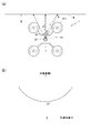
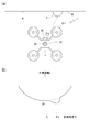
- It is a conceptual diagram which shows the control in the said flight type inspection apparatus (a) is a perspective view, (b) is a side view.
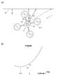
- It is a figure explaining the estimation method of a facing parameter (a) is a top view and (b) has shown the ranging result about the state in which the camera is facing the object surface.
- It is a figure explaining the estimation method of a facing parameter (a) is a top view and (b) has shown the ranging result about the state where the camera is not facing the object surface directly.
- a flight type inspection apparatus (hereinafter sometimes simply referred to as an inspection apparatus) 1 according to the present embodiment is a planar inspection target such as a wall surface of a building, particularly a planar inspection target standing substantially vertically. The state of the target surface W is inspected without contact.
- FIG. 1 is a perspective view showing an appearance of a flight type inspection apparatus 1 according to an embodiment of the present invention.
- the flight type inspection apparatus 1 mainly includes a multicopter 91 that is a small unmanned airplane including a plurality (four in this case) of rotating wings 911, a distance measuring sensor 20 attached to the multicopter 91, a camera 30, and the like. have.
- the four rotor blades 911 are radially provided on substantially the same plane, and the axis a perpendicular to the center of the plane is called the yaw axis, and the rotation angle around the yaw axis a is This is called the yaw angle.
- a direction along a pair of sides of a square having four rotor blades 911 as apexes is a front-rear direction b, and a direction along another pair of sides is a left-right direction c.
- the yaw axis a is directed in the vertical direction.
- the ranging sensor (ranging unit) 20 is attached to the upper center portion of the multicopter 91.
- the distance measuring sensor 20 is a sensor capable of measuring a distance (ranging) between an external object and a target surface W in this case with respect to a specific direction. A known distance measuring sensor using the reflection of can be used.
- the distance measuring sensor 20 includes a base portion 22 fixed to the multicopter 91 and a rotating portion 21 that can rotate with respect to the base portion 22.
- the rotating unit 21 is provided with a laser light source and a detecting unit. By rotating the shaft relative to the base, the laser beam B is emitted continuously in a plurality of directions within the rotation range. The distance to an external object can be measured.
- the distance measuring axis that is the rotation center of the rotating unit 21 is coincident with the yaw axis a of the multicopter 91, and by rotation, the distance is measured in a predetermined angle range about the yaw axis a toward the front.
- the angle range in which the measurement is performed is 60 ° or more on one side centered on the front front, and 120 ° or more in total.
- the camera 30 as an inspection unit is fixedly attached to the front of the multicopter 91, facing straight ahead. Thereby, an object existing in front of the multicopter 91, here, the target plane W can be photographed.
- the shooting direction of the camera 30 matches the front direction of the distance measuring sensor 20.
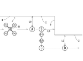
- FIG. 2 is a block diagram showing a functional configuration of the flight type inspection apparatus 1.
- the multicopter 91 is mainly composed of a flight controller 83 that controls the attitude and flight operation of the multicopter 91 in the air, a plurality of rotor blades 911 that generate lift by rotating the multicopter 91, and a pilot (transceiver 81).
- a transmitter / receiver 82 that performs wireless communication with the battery
- a battery 84 that supplies electric power thereto.
- the flight controller 83 includes a control unit 831 that is a microcontroller.
- the control unit 831 includes a CPU that is a central processing unit, a RAM / ROM that is a storage device, and a PWM controller that controls the DC motor 86.
- the DC motor 86 is coupled to each rotary blade 911, and the rotational speed of each DC motor 86 is controlled via an ESC (Electric Speed Controller) 85 in accordance with an instruction from the PWM controller.
- ESC Electrical Speed Controller
- the balance of the rotational speeds of the four rotor blades 911 controls the attitude of the multicopter 91 including the yaw angle and the movement in the vertical a, front-rear b, and left-right c directions.
- the flight controller 83 includes a sensor group 832 and a GPS receiver 833, which are connected to the control unit 831.
- the sensor group 832 of the multicopter 91 includes an acceleration sensor, a gyro sensor (angular velocity sensor), an atmospheric pressure sensor, a geomagnetic sensor (electronic compass), and the like.
- the RAM / ROM of the control unit 831 stores a flight control program in which a flight control algorithm during the flight of the multicopter 91 is implemented.
- the control unit 831 can control the attitude and position of the multicopter 91 by the flight control program using information acquired from the sensor group 832.
- the flight operation of the multicopter 91 can be performed manually by the operator via the transceiver 81.
- an autonomous flight program in which a flight plan such as GPS coordinates, altitude, and flight route is parameterized may be separately installed and configured to fly autonomously.
- this embodiment deals with a case where the operator manually performs a flight operation via the transceiver 81.
- flight control based on an external signal transmitted from the transceiver 81 can be read as control in autonomous flight using a GPS signal as an external signal.
- the distance measuring sensor 20 and the camera 30 are also connected to the control unit 831.
- the distance measuring sensor 20 measures the distance to the target surface W in each direction while rotating the rotating unit 21, and transmits the measurement result to the control unit 831.
- the camera 30 is instructed to perform shooting by the control unit 831, and various shooting conditions are controlled as necessary.
- data of the captured image is transmitted to the control unit 831 and stored in the RAM / ROM.
- the estimation unit 40 is provided in the CPU of the control unit 831 as part of the calculation function.
- the estimation unit 40 processes information on the result of measurement by the distance measuring sensor 20 input to the control unit 831, and estimates the facing parameter of the camera 30 with respect to the target surface W. That is, the two parameters of the angle of the camera 30 with respect to the target surface W and the distance of the camera 30 from the target surface W in the angular direction are estimated. Details of the face-to-face parameter estimation will be described later.
- the control unit 831 can control the position and orientation of the multicopter 91 based on the estimation result of the facing parameter in the estimation unit 40.
- the control unit 831 controls the attitude and position of the multicopter 91 based on both the estimation result of the facing parameter in the estimation means 40 and the external signal sent from the pilot via the transceiver 81 as described above. The role of each of these two types of control is described in the next section.
- the distance measuring sensor 20 has the rotating unit 21 and the distance measuring axis is one that can continuously scan the measurement direction over a predetermined angle range around one rotation axis. In the plane perpendicular to the axis, the distance to the target surface (target distance) can be measured continuously in each measurement direction.
- a rotary distance measuring sensor 20 it is possible to estimate the facing parameter with high accuracy using only one sensor.
- any distance measuring sensor capable of measuring a target distance in a plurality of measurement directions can be used without being limited to this type.
- a plurality of distance measuring sensors whose measurement directions are fixed may be arranged toward a plurality of measurement directions around the distance measuring axis.
- the fixed type sensor is less expensive than the rotary type sensor, but has excellent durability.
- the multicopter 91 is rotated around the yaw axis a and the distance measurement is performed a plurality of times, even if the number of fixed distance measuring sensors is small, it can be compensated and the target distance can be adjusted for a large number of measurement directions. Measurement can be performed.
- the rotary distance measuring sensor 20 when used, it is not limited to one that rotates around one rotation axis and can scan the measurement direction one-dimensionally, but one that can scan the measurement direction two-dimensionally is used. May be. However, as described above, the distance measuring sensor 20 that rotates around one rotation axis is arranged on the yaw axis a of the multicopter 91 or on an axis parallel to the yaw axis a. By attaching it, it is possible to contribute to stabilization of photographing by the camera 30 when photographing the target surface W set up substantially vertically by the camera 30 while simply suppressing the configuration of the distance measuring sensor 20.
- the distance measuring sensor 20 is not limited to the one using the laser, but the information on the distribution of the target distance measured in each measurement direction is used for the estimation of the facing parameter. It is preferable that
- the camera 30 is used as the inspection unit.
- the camera 30 is used as the inspection unit.
- the other inspection units include non-contact type spectroscopic devices, ultrasonic inspection devices, electromagnetic measurement devices, temperature measurement devices, and the like.
- the camera 30 in order to perform imaging using the camera 30 from the front of the target surface W, the camera 30 is arranged facing forward as in the distance measuring sensor 20, but depending on the type of the inspection unit, If it is appropriate to inspect from an obliquely set direction, an inspection unit may be installed with an angle between the distance measuring sensor 20 and the appropriate distance.
- the camera 30 is fixed to the multicopter 91. However, the inspection unit including the camera 30 can rotate around the yaw axis a or another axis with respect to the multicopter 91, or can be positioned. You may attach so that movement is possible.
- FIG. 3 shows an outline of the inspection of the target surface W using the flight type inspection apparatus 1 having the above-described configuration with the wall surface of the building erected substantially vertically as the target surface W.
- the inspection apparatus 1 in the middle of inspecting the target surface W makes the yaw axis a of the multicopter 91 vertical, and sets the front direction (+ b direction). It faces the target surface W.
- the left and right axes ( ⁇ c directions) are oriented parallel to the width direction of the target surface W.
- the inspection apparatus 1 uses the distance measuring sensor 20 to continuously perform distance measurement for measuring the distance (target distance) to the target surface W in a plurality of measurement directions, 831 controls the position and posture of the multicopter 91.
- Information on the target distance obtained by the distance measuring sensor 20 is processed in real time by the estimation means 40 of the control unit 831, and the facing parameter of the camera 30 with respect to the target surface W is estimated.
- the distance measuring sensor 20 is one that scans the measurement direction in a one-dimensional manner in a plane perpendicular to the yaw axis a of the multicopter 91, the distance measurement sensor 20 is used for the target surface W included in the facing parameter.
- the angle of the inspection unit refers to the yaw angle ⁇ in the direction in which the inspection unit faces the target surface W around the yaw axis a.
- the control unit 831 continuously executes imaging of the target surface W by the camera 30, that is, inspection by the inspection unit, in addition to flight control including estimation of the facing parameter by the estimation unit 40.
- the inspection device 1 moves in a zigzag manner along the target surface W by the movement of the multicopter 91.
- This movement of the multicopter 91 along the target surface W is performed by changing the position of the translation direction along the vertical direction ( ⁇ a direction) and the horizontal direction ( ⁇ c direction).
- the change of the position in the vertical direction and the horizontal direction is executed by the control unit 831 based on an external signal received from the transmitter / receiver 81 operated by the operator.
- the multicopter 91 faces the target surface W directly along the plane N in the plane perpendicular to the target surface W.
- the distance D between the camera 30 and the target surface W is kept constant. That is, the control unit 831 controls the facing parameter of the multicopter 91 so that the yaw angle ⁇ of the multicopter 91 and the distance D in the translation direction along the front-rear direction ( ⁇ b direction) are maintained constant.
- the signals related to the control of the yaw angle ⁇ and the distance D in the front-rear direction can also be transmitted from the transceiver 81 by the operator, but the control unit 831 is transmitted from the transceiver 81 regarding the control of these two parameters.
- the control is performed based on the information of the facing parameter estimated by the estimating means 40 from the measurement result of the distance measuring sensor 20 as described above without following the external signal.
- the multicopter 91 is moved in the direction along the target surface W while maintaining the camera 30 facing the target surface W in a direction perpendicular to the plane N by a certain distance. .
- photographing by the camera 30 is performed at a plurality of positions on the target surface W.
- Shooting may be performed intermittently by temporarily hovering the multicopter 91 in the course of the movement path along the target surface W, or may be performed while continuously moving the multicopter 91.
- the direction suitable for the inspection using various inspection units and It is possible to inspect each part of the target surface W stably at a distance.
- the direction and distance of the multicopter 91 with respect to the target surface W that is, the control of the facing parameter is not performed based on the external signal from the transceiver 81 or the like, but the distance measurement attached to the multicopter 91 itself.
- the multicopter 91 for the target surface W is derived from the external signal.
- the facing parameter is highly controlled, and the inspection can be performed while keeping it constant. As a result, it is possible to perform a high-accuracy inspection under a stable inspection condition over a wide range of the inspection surface. As a factor that destabilizes the facing parameter due to the external signal, for example, it is extremely difficult to keep the facing parameter constant in a manual operation by the operator.
- Constant includes an error that is permissible as a variation in inspection conditions in the inspection unit. “Constant” means that the value of the target facing parameter is changed not only when maintaining the same facing parameters from the beginning to the end of the inspection, but also during the inspection according to changes in the inspection conditions, etc. It may be.
- the estimation unit 40 estimates and the control unit 831 maintains constant.
- the angle with respect to the target surface W constituting the facing parameter refers only to the yaw angle ⁇ with respect to the target surface W.
- the pitch angle (the rotation angle around the axis c) can be estimated as facing parameters and can be controlled to be constant.
- the control unit 831 performs a multicopter for the target surface W.
- the angle and distance of 91 itself are controlled, when the inspection part is attached to the multicopter 91 so as to be rotatable or movable, the angle and distance of the multicopter 91 itself with respect to the target surface W are controlled.
- rotation and position movement of the inspection unit with respect to the multicopter 91 may be controlled.
- the facing parameter of the inspection unit with respect to the target surface W is controlled based on the estimation information by the estimation unit 40 instead of the external signal, while along the target surface W.
- the camera 30 takes a picture while the multicopter 91 is translated based on an external signal from the transceiver 81. Accordingly, the inspection apparatus 1 can be moved with a high degree of freedom in a wide region along the target surface W.
- control unit 831 that has received an external signal refers to information related to the plane perpendicular direction N estimated by the estimation means 40 based on the measurement result of the distance measuring sensor 20, and the plane perpendicular direction N If translation is performed in a plane perpendicular to the axis, high accuracy can be obtained with respect to the direction of translation.
- the facing parameter of the camera 30 with respect to the target surface W that is, the angle of the camera 30 with respect to the target surface W, based on the information on the target distance in each direction obtained by the distance measuring sensor 20, and its
- the face-to-face parameter is defined for the camera 30 from the viewpoint of keeping the shooting conditions of the camera 30 constant, but for the sake of simplicity, the face-to-face parameter is set to face the center point of the multicopter 91.
- a distance measuring axis of the distance measuring sensor 20 is provided at the center point of the multicopter 91. Since the mounting position and mounting angle of the camera 30 with respect to the multicopter 91 are known, if the facing parameter for the center point of the multicopter 91 is determined, the facing parameter for the camera 30 is also automatically determined.
- the target plane is a substantially vertical plane
- the yaw axis a of the multicopter 91 is vertical as shown in FIG. 3, and the front direction (+ b direction)
- the front direction (+ b direction) of the multicopter 91 coincides with the surface normal direction N of the object surface W.
- a plan view of this state is shown in FIG.
- the measurement direction ⁇ of the distance measuring sensor 20 is changed around the yaw axis a
- the target distance L that is the distance to the target surface W measured in each measurement direction is shown as a function of the measurement direction ⁇ . Shown in 4 (b).
- the target distance L is minimum at L0.
- the constant L0 corresponds to the distance from the center point of the multicopter 91 along the perpendicular direction N to the target surface W.
- the control unit 831 multi-copter 91 so as to maintain the facing parameters ⁇ and D as they are. Control may be performed.
- the control unit 831 changes the position of the multicopter 91 along the perpendicular direction N so that the distance D matches the target distance without changing the yaw angle ⁇ . Control may be performed.
- the control unit 831 is simultaneously orthogonal to the plane perpendicular direction N estimated above while referring to the signal from the transceiver 81. What is necessary is just to move the multicopter 91 in the direction to do.
- the angle (yaw angle ⁇ ) of the multicopter 91 with respect to the target surface W is equal to ⁇ a, which is an angle obtained by inverting the sign of the measurement direction ( ⁇ a) at the minimum point, and the angular direction
- ⁇ a is an angle obtained by inverting the sign of the measurement direction ( ⁇ a) at the minimum point
- the control unit 831 may control the facing parameters ⁇ and D.
- the multicopter 91 by changing the yaw angle ⁇ of the multicopter 91 and rotating it by ⁇ a, the multicopter 91 is directly opposed to the target surface W, and the distance D from the target surface W of the multicopter 91 after the direct alignment matches the target distance.
- Control to change the position of the multicopter 91 along the perpendicular direction N may be performed.
- the control unit 831 moves the multicopter 91 in a direction orthogonal to the estimated perpendicular direction N with respect to the multicopter 91 after the facing while referring to the signal from the transmitter / receiver 81. Good.
- the measurement direction ⁇ that gives the minimum point at the target distance L as a function of the measurement direction ⁇ is regarded as the plane perpendicular direction N orthogonal to the target surface W, so that the multicopter 91 can be easily faced.
- the parameters ⁇ , D can be estimated.
- estimation of the perpendicular direction N and estimation of the facing parameters ⁇ and D may be performed using an analytical function such as the above formula (1) or formula (2).
- the target surface is a curved surface
- the target distance L does not necessarily take the minimum value in the plane perpendicular direction N where the multicopter 91 faces the target surface W.
- the shape of the curved surface of the target surface W is known from structure design information or the like, the shape is approximated to a simple mathematical expression such as an arc, and the mathematical expression is expressed by the above formulas (1) and (2).
- An analytical expression reflecting the curved surface shape may be created by superimposing. Then, the facing parameters ⁇ and D may be estimated using the created analytical expression in the same manner as described above.
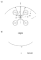
- the target surface W is a gentle inwardly convex shape (the target surface on the opposite side to where the multicopter 91 is disposed across the surface of the target surface W). If the shape is convex toward the inside, the estimation can be simplified. In such a case, the relationship between the measurement direction ⁇ and the target distance L is as shown in FIG. The shape of this curve corresponds to that in which the curve in the case of FIG. That is, also in this case, as in the case where the target surface W is planar, it is possible to apply the estimation that the measurement direction ⁇ that gives the minimum point is the perpendicular direction N.
- the “gradual” inwardly convex shape to which such estimation can be applied means the curvature of the target surface W rather than an arc having a radius L0 from the center of the multicopter 91 along the plane perpendicular direction N to the target surface W. Is small (the radius of curvature is large). If the curvature of the target surface W becomes larger than this, the target distance L may take a minimum value in a direction deviating from the perpendicular direction N.
- the estimation unit 40 cannot correctly estimate the yaw angle ⁇ to which the perpendicular direction N and the multicopter 91 are directed. Therefore, when a behavior in which the target distance L does not change with respect to the measurement direction ⁇ is observed over a predetermined measurement range (for example, 15 °) within a predetermined reference range, the distance from the center of the multicopter 91 is determined.
- a predetermined measurement range for example, 15 °
- the multicopter 91 when it is estimated that an inwardly convex structure having a curvature radius equal to the distance L0 from the center of the multicopter 91 is present on the target surface W, the multicopter 91 is moved in the direction along the target surface W.
- the inwardly convex portion may be imaged by the camera 30 while rotating around the yaw axis a on the spot and changing the yaw angle ⁇ by a predetermined angle step.
- the angle step for changing the yaw angle ⁇ at the time of shooting is preferably determined based on the camera angle of view. In this type of shooting, continuous image shooting areas are often set to overlap by 30% to 66%. For example, when the angle of view of the camera is ⁇ , the overlap ratio is set to 50%. For example, the angle step may be set to 0.5 ⁇ , and if the overlap ratio is 30%, the angle step may be set to 0.7 ⁇ .
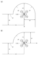
- FIG. 7 shows the movement trajectory of the multicopter 91 with a dotted line when the target surface W has an inwardly convex structure having the same radius of curvature as the distance L0 from the center of the multicopter 91.
- FIG. 7A shows a case where the inwardly convex structure is formed over 180 °
- FIG. 7B shows a case where the inwardly convex structure is formed over 90 °.
- the multicopter 91 temporarily stops the movement along the surface of the target surface W at the point R that is the center of the inwardly convex structure, and rotates around the yaw axis a on the spot. Then, imaging is performed for each part of the inwardly convex part.
- the rotation angle at the point R is 180 ° in FIG. 7A and 90 ° in FIG. 7B. 7 (a) and 7 (b), the movement of the multicopter 91 from the linearly flying portion on the left side to the point R causes the target surface W indicated by item [4] below to be bent. Is performed according to the estimation and control method.
- the relationship between the measurement direction ⁇ and the target distance L is as shown in FIG.
- a large downward convex structure is seen in a part of the measurement direction ⁇ centered on the direction ⁇ p connecting the multicopter 91 and the projection P, and the function form estimated in the other measurement direction ⁇ is large.
- the facing parameters ⁇ and D may be estimated while ignoring the part where such a deviation exists.
- the measurement points of the ignored parts are interpolated, and the interpolated function form is the same as the case where the projection P shown in [1] does not exist.
- the facing parameters ⁇ and D may be estimated.
- approximation may be performed using an analytical expression such as the above formula (1) or formula (2).
- FIG. 8B a curve interpolated using the equation (1) is indicated by a broken line.
- the facing parameters ⁇ and D of the multicopter 91 it is possible to accurately estimate the facing parameters ⁇ and D of the multicopter 91 with the original target surface W as a reference while eliminating the influence of the protrusion P. Further, in the estimated face-to-face parameters ⁇ , D, the distance from the target surface W to the multicopter 91 is too small, and there is a concern that a collision with the projection P may occur due to a flight position error or the like. For example, it is possible to take measures such as changing the target value of the distance D to the target surface W so as to increase. As described above, when the facing parameters ⁇ and D are estimated by ignoring the measurement results in some measurement directions ⁇ , it is necessary to measure the target distance L in at least three measurement directions ⁇ . is there.
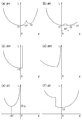
- the multicopter 91 is set in the order of A ⁇ B ⁇ C ⁇ D along the bend while keeping a fixed distance L0 and facing each of the parts X, Y, Z orthogonal to each other. Let it fly.
- the relationship between ⁇ and the target distance L is as shown in FIG.
- two local minimum points C1 and C2 are observed.
- the local minimum point C1 located in the measurement direction (the side where ⁇ is small) behind the moving direction of the multicopter 91 corresponds to the perpendicular direction N of the part X facing the multicopter 91.
- the minimum point C2 located in the measurement direction ( ⁇ -larger side) ahead of the movement direction of the multicopter 91 measures the distance to the part Y (second part) existing in front of the movement direction along the movement direction. Corresponding to what you are doing.
- the graph curves on both sides of the two minimum points C1 and C2 are approximated by the functions of the equations (1) and (2), respectively.
- the estimating means 40 faces the front in the direction closer to the multicopter 91 in the moving direction of the multicopter 91, that is, the multicopter with respect to the part X. It is estimated that the site
- the target distance L at the minimum point C2 decreases, and eventually the target distance L at the minimum point C2 becomes smaller as shown in FIG. It becomes equal to L0 which is the object distance L in the other minimum point C1.
- L0 which is the object distance L in the other minimum point C1.
- the multicopter 91 has reached a point B that is a distance L0 away from both the part X and the part Y.
- the difference in the measurement direction ⁇ between the minimum point C1 and the minimum C2 is equal to the angle between the part X and the part Y, and in this case, 90 °.
- the control unit 831 maintains the facing parameters ⁇ , D for the part Y from the control state (first control state) where the facing parameters ⁇ , D for the part X are kept constant. Transition to the control state (second control state). That is, the yaw angle ⁇ of the multicopter 91 is rotated by an angle equal to the difference in the measurement direction ⁇ between the local minimum point C1 and the local minimum point C2, here 90 °, and the region Y from the state of facing the region X at the distance L0. Is switched to the state of facing directly at the distance L0. Then, the flight continues parallel to the part Y.
- estimation and control switching methods are not limited to the case where the part X and the part Y are bent at right angles, but can be applied to cases having an arbitrary bending angle. In order to distinguish, it is preferable to apply only when there is a bend angle of 45 ° or more and the difference in the measurement direction ⁇ between the minimum point C1 and the minimum point C2 is 45 ° or more (see FIG. 8B). ).
- the multicopter 91 moves parallel to the part Y while facing the part Y (third part) at a distance L0.
- the multicopter 91 continues to fly parallel to the part Y as it is, the part Y and the other part of the target surface W do not exist in front of the multicopter 91.
- the relationship between the measurement direction ⁇ and the target distance L is as shown in FIG.
- There is a minimum point in the region of ⁇ ⁇ 0 the side where ⁇ is smaller than the minimum point corresponds to the region where the target distance L with respect to the part Y is measured, and the side where ⁇ is larger than the minimum point is This corresponds to the region in which the target distance L with respect to the part Z is measured.
- the multicopter 91 is closer to the part Y than the part Z, so the curve on the side where ⁇ is smaller than the minimum point has a gentler curve.
- the measurement direction ⁇ at the minimum point has an absolute value equal to half the angle between the part Y and the part Z, and in this case is ⁇ 45 °.
- the control unit 831 maintains the facing parameters ⁇ , D for the part Z from the control state (third control state) where the facing parameters ⁇ , D for the part Y are kept constant. Transition to the control state (fourth control state). That is, the yaw angle ⁇ of the multicopter 91 is rotated by an angle corresponding to twice the absolute value of the measurement direction ⁇ that gives the minimum point, here 90 °, and the distance L0 from the state facing the part Y at the distance L0 to the part Z. Switch to the right-facing state with. Then, the flight continues parallel to the part Z.
- the multicopter 91 flies parallel to the part Z while facing the part Z at a distance L0.
- the relationship between the measurement direction ⁇ and the target distance L is as shown in FIG.
- the target distance L increases discontinuously.
- the direction of the multicopter 91 is changed by using the distance measurement result of the distance measurement sensor 20 to follow the bent structure often seen on the wall surface of the building, etc., without being controlled by an external signal. be able to. Thereby, even if there exists a bending structure, the flight of the multicopter 91 and imaging
- the inspection method according to the present embodiment inspects the state of the target surface W, which is a planar inspection target, using the flight type inspection apparatus 1 according to the above embodiment.
- control unit 831 built in the flight type inspection apparatus 1 estimates and controls the facing parameters ⁇ and D with respect to the target surface W, and is combined with a fixed camera 51 as an imaging unit and an external control unit.
- An inspection method for controlling movement in the direction along the target surface W using the control computer 52 will be described.
- the outer wall surface of the building is the target surface W
- the camera 30 of the flight type inspection apparatus 1 is opposed to the target surface W at a certain distance in a zigzag manner. While the multicopter 91 is flying, photographing is continuously performed on each part of the target surface W.
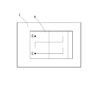
- the fixed camera 51 is installed on the ground at a position away from the flight position of the multicopter 91. As indicated by a thin line in the figure, the entire target surface W is accommodated in the field of view of the fixed camera 51, and while the target surface W is inspected, the state of the target surface W is continuously photographed by the fixed camera 51. In a state where the inspection apparatus 1 is flying along the target surface W, the inspection apparatus 1 is also reflected in the captured image I captured by the fixed camera 51.
- the fixed camera 51 is connected to a control computer 52, and the control computer 52 receives a captured image I captured by the fixed camera 51.
- control computer 52 determines a trajectory for causing the multicopter 91 of the inspection apparatus 1 to fly along the target plane W based on the captured image I, and transmits an external signal s to the multicopter 91.
- the multicopter 91 is actually moved along the target surface W according to the determined locus. Since the captured image I is a two-dimensional image, the direction ⁇ and the distance D of the inspection apparatus 1 with respect to the target surface W cannot be recognized from the captured image I.
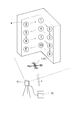
- FIG. 12 shows this path superimposed on a captured image I that is captured by the fixed camera 51 and sent to the control computer 52.
- the control computer 52 controls the inspection apparatus 1 waiting at a position away from the target surface W (for example, in the vicinity of the control computer 52) in the three-dimensional direction and guides it straight to the start point S.
- the inspection apparatus 1 is recognized on the captured image I captured by the fixed camera 51.
- the inspection apparatus 1 starts distance measurement by the distance measurement sensor 20, and estimates the facing parameters ⁇ and D in the estimation means 40 of the control unit 831 based on the result.
- the multicopter 91 is directly opposed to the target surface W, and a state where the multicopter 91 is separated from the target surface W by a predetermined distance is taken.
- the control computer 52 sends an external signal s to the multicopter 91, and moves the multicopter 91 up and down within a plane parallel to the target plane W according to the locus defined on the captured image I as shown in FIG. Move left and right.
- feedback control is performed while confirming the captured image I in real time so that the multicopter 91 moves according to the intended trajectory.
- the inspection apparatus 1 continues the distance measurement by the distance measurement sensor 20 and the estimation of the face-to-face parameters ⁇ and D based on the distance measurement, and keeps the state of facing the target surface W at a constant distance.
- the external parameters s do not contribute to the control of the control parameters ⁇ and D, and are performed in a self-contained manner.
- the inspection apparatus 1 maintains a certain distance with respect to each part of the target surface W as described above. The direction is automatically changed.
- the external device of the inspection apparatus 1 such as the fixed camera 51 and the control computer 52 is used to control the direction along the target surface W, and by the control by the inspection apparatus 1 itself without using the external signal s, By performing control in a direction perpendicular to the target surface W, it is possible to perform high-precision inspection on a wide region of the target surface W while maintaining constant inspection conditions.
- the inspection device 1 and the target surface W can be kept constant regardless of the external signal s, so that even if the movement trajectory of the inspection apparatus 1 is set so as to overlap the obstacle, the distance between the obstacle and the target surface W can be maintained.
- the inspection device 1 can be made to fly and inspected without being affected by an obstacle.
- a camera that captures the target surface W in a planar manner is used as the fixed camera 51.
- a stereoscopic camera may be used to capture a stereoscopic image.
- the fixed camera 51 can recognize the distance between the target surface W and the inspection apparatus 1 to some extent. Thereby, the guidance
- information from the stereo camera is used supplementarily, so that when the distance measuring sensor 20 has a disturbance such as a sudden failure or an obstacle such as a bird.
- control unit 831 automatically follows the concave structure such as the points 1, 4, 7, and 10, and the convex structure such as the points 2, 3, 8, and 9 follows.
- the control unit 831 can automatically follow.
- the control computer 52 that recognizes the captured image I of the fixed camera 51 transmits to the inspection apparatus 1 that there is a concave structure or a convex structure in these parts, it is possible to more accurately follow the structure. It can be carried out.
Abstract
小型無人飛行機を利用して、面状の検査対象に対する角度および距離を制御しながら、検査を行うことができる飛行型検査装置および検査方法を提供する。 複数の回転翼911と制御部とを有する小型無人飛行機91と、小型無人飛行機91に取り付けられ、対象面の状態を非接触にて検査する検査部30と、対象面までの距離である対象距離を複数の計測方向に対して計測する測距部20と、を備える飛行型検査装置1を用いる。制御部は、測距部20によって計測された対象距離に基づいて、検査部30の対象面に対する角度および該角度における対象面からの距離よりなる対面パラメータを推定する推定手段を備え、飛行型検査装置1は、その推定結果に基づいて、検査部30の対象面に対する対面パラメータを一定に維持しながら、対象面に沿って小型無人飛行機91を移動させ、対象面の複数の位置に対して検査部30による検査を行う。
Description
本発明は飛行型検査装置に関し、さらに詳しくは、複数の回転翼を備える小型無人飛行機を用いて面状の検査対象を非接触にて検査する飛行型検査装置およびそれを用いた検査方法に関するものである。
従来一般に、ビルの外壁面等、大型の構造物における略鉛直に立設された面の状態を検査するに際し、特許文献1に示されるように、ロープ等を介して構造物にゴンドラを取り付け、ゴンドラに作業者が搭乗して、検査作業を行ってきた。あるいは、ゴンドラに検査機器を取り付け、無人で検査を行ってきた。
一方で、近年、産業用無人ヘリコプターに代表される小型の無人飛行機(UAV)、特に小型のマルチコプターが、急速に普及し、広範な分野への導入が試行されている。マルチコプターは複数のロータが搭載されたヘリコプターの一種であり、これら各ロータの回転速度を調節することにより機体のバランスをとりながら飛行する。
大型の構造物の面に対する検査において、ゴンドラを構造物に取り付けて検査を行う代わりに、小型無人飛行機に検査機器を搭載し、検査対象となる面に沿って飛行させながら、面の各部に対して順次検査を行うという方法が考えられる。すると、検査工程を大幅に簡素化、また高精度化できる可能性がある。
構造物の表面の検査、特に非接触型の検査においては、検査精度を担保する観点から、構造物の表面に対して、検査装置を、一定の角度、一定の距離に配置して検査を行うことが重要である。よって、小型無人飛行機に検査機器を搭載する場合に、小型無人飛行機を、検査対象の面に対して、一定の角度、一定の距離を維持して飛行させる制御を行いながら、面の各部に対する検査を行うことが望ましい。
しかし、小型無人飛行機の中で特に普及が進んでいる操縦者が遠隔から飛行を制御する形式のものの場合、検査対象の面に対して、一定の角度、一定の距離を維持しながら小型無人飛行機を飛行させるには、高度の熟練が必要である。操縦者の熟練の程度が低いと、検査精度が低くなってしまうだけでなく、小型無人飛行機が検査対象の面に衝突してしまう可能性すらある。
操縦者の操縦によるのではなく、GPSや高度センサを用いて、一定の範囲で小型無人飛行機を自律的に飛行させる機構も導入が進んでいるが、この場合にも、GPS信号が検査対象の構造物によって反射や遮蔽を受けることや、長時間の飛行で高度センサに誤差が生じやすいこと等により、検査対象の面に対する角度および距離を一定に制御しながら小型無人飛行機を飛行させることは難しい。特に、トンネルの内壁面や高架橋の橋脚等、検査対象面の上方に障害物が存在する構造物を検査対象とする場合には、GPSを利用した自律飛行によって検査を行うことは極めて困難である。
本発明が解決しようとする課題は、小型無人飛行機を利用して、面状の検査対象に対する角度および距離を制御しながら、検査を行うことができる飛行型検査装置および検査方法を提供することにある。
上記課題を解決するため、本発明の飛行型検査装置は、複数の回転翼と、該複数の回転翼による飛行を制御する制御部と、を有する小型無人飛行機と、前記小型無人飛行機に取り付けられ、面状の検査対象である対象面の状態を非接触にて検査する検査部と、前記対象面までの距離である対象距離を複数の計測方向に対して計測する測距部と、を備える飛行型検査装置において、前記制御部は、前記測距部によって計測された前記対象距離の情報に基づいて、前記検査部の前記対象面に対する角度および該角度における前記対象面からの距離よりなる対面パラメータを推定する推定手段を備え、前記飛行型検査装置は、前記推定手段における推定結果に基づいて、前記検査部の前記対象面に対する前記対面パラメータを一定に維持しながら、前記対象面に沿って前記小型無人飛行機を移動させ、前記対象面の複数の位置に対して前記検査部による検査を行うものである。
ここで、前記測距部は、測距軸に垂直に複数の計測方向に対して前記対象距離を計測し、前記推定手段は、前記検査部の前記対象面に対する角度として、前記測距軸に垂直な面内における前記検査部の角度を推定するとよい。
この場合に、前記測距軸は、前記小型無人飛行機のヨー軸上または該ヨー軸と平行に設けられるとよい。
また、前記制御部は、外部からの信号に基づいて、前記小型無人飛行機の位置および姿勢を変更することができ、前記検査部による検査を行う間は、前記小型無人飛行機の前記対象面に対する前記対面パラメータの制御を、前記外部からの信号に基づかず、前記推定手段における推定の結果に基づいて行うとともに、前記小型無人飛行機の前記対象面に沿った位置の制御を、前記外部からの信号に基づいて行うとよい。
前記測距部は、前記小型無人飛行機に回転可能に取り付けられており、該回転によって前記対象距離を前記複数の計測方向に対して計測するとよい。
前記推定手段は、前記計測方向の関数としての前記対象距離が極小値をとる計測方向を、前記対象面に直交する面直方向であるとして、前記対面パラメータの推定を行うとよい。
前記推定手段は、前記対象距離をL、前記面直方向を基準とした前記計測方向をθ、前記面直方向に沿った前記測距部から前記対象面までの距離をL0として、L=L0/cosθの関数形を用いて、前記対面パラメータの推定を行うとよい。
前記測距部は、3つ以上の計測方向に対して前記対象距離を計測し、前記推定手段は、一部の計測方向における対象距離と計測方向との間の関係が、該一部以外の計測方向における該関係から推定される関数形から逸脱していれば、該一部の計測方向の計測結果を無視して前記対面パラメータの推定を行うとよい。
前記制御部が、前記対象面の第一の部位に対する前記検査部の前記対面パラメータを一定に維持する第一の制御を行いながら、前記小型無人飛行機を前記第一の部位に平行に移動させている状態において、前記推定手段は、前記計測方向の関数としての前記対象距離に2つの極小点が存在し、該2つの極小点のうち前記小型無人飛行機の移動方向前方の計測方向に位置する極小点における対象距離が、前記小型無人飛行機の移動に伴って小さくなるのを検出すると、前記移動方向の前方に、前記小型無人飛行機に近づく方向に面を向けた第二の部位が前記対象面に存在すると推定し、前記制御部は、前記2つの極小点における前記対象距離が等しくなった時に、前記第二の部位に対する前記検査部の前記対面パラメータを一定に維持する第二の制御に、前記第一の制御から移行するとよい。
前記制御部が、前記対象面の第三の部位に対する前記検査部の前記対面パラメータを一定に維持する第三の制御を行いながら、前記小型無人飛行機を前記第三の部位に平行に移動させている状態において、前記推定手段は、前記計測方向の関数としての前記対象距離が無限大となる挙動を検出すると、前記小型無人飛行機の移動方向の前方に、前記小型無人飛行機から離れる方向に面を向けた第四の部位が前記対象面に存在すると推定し、前記制御部は、前記対象距離が無限大となる計測方向よりも前記移動方向後方の計測方向において、極小点を挟んで前記対象距離が対称となった状態を検出した時に、前記第四の部位に対する前記検査部の前記対面パラメータを一定に維持する第四の制御に、前記第三の制御から移行するとよい。
本発明にかかる検査方法は、上記のような飛行型検査装置を用いて面状の検査対象である対象面の状態を検査するものである。
ここで、前記対象面に対して固定され、前記小型無人飛行機よりも離れた位置から前記対象面を撮影する撮影手段と、前記撮影手段に撮影された前記対象面の撮影像を基に、前記小型無人飛行機の位置および姿勢を制御することができる外部制御手段と、を用い、前記制御部によって、前記検査部の前記対象面に対する前記対面パラメータを一定に維持しながら、前記外部制御手段によって、前記対象面に沿って前記小型無人飛行機を移動させ、前記対象面の検査を行うとよい。
上記発明にかかる飛行型検査装置は、対象面までの距離を複数の計測方向に対して計測する測距部と、その測距部での計測結果に基づいて、検査部の対象面に対する角度およびその角度方向における対象面からの距離よりなる対面パラメータを推定する推定手段を備えている。その推定結果に基づいて、対象面を基準とした検査部の角度と距離を制御しながら、小型無人飛行機を対象面に沿って移動させることで、対象面との間に、検査部による検査に適した方向と距離を維持しながら、対象面の各部に対して、安定した条件で検査を行うことができる。これにより、簡便かつ高精度に、対象面の検査を行うことができる。
ここで、測距部が、測距軸に垂直な複数の計測方向に対して対象距離を計測し、推定手段が、検査部の対象面に対する角度として、測距軸に垂直な面内における検査部の角度を推定する場合には、測距軸に垂直な面内における検査部の角度と、その角度方向における対象面からの検査部の距離を、高精度に見積もることができる。その結果、計測方向を単一面内に設定した簡素な測距部を用いて、少なくとも測距部に垂直な面内において、検査部と対象面の間の角度および距離を高精度に制御して、対象面の検査を行うことができる。
この場合に、測距軸が、小型無人飛行機のヨー軸上または該ヨー軸と平行に設けられる構成によれば、略鉛直に立設された対象面において、ヨー軸を略鉛直に向けて小型無人飛行機を飛行させながら検査を行えば、ヨー軸をはじめとする小型無人飛行機自体の制御軸に、対象面を基準とした小型無人飛行機の制御および運動の座標軸を一致させることができる。これにより、制御部における制御の方式を簡素化することができる。そして、検査部と対象面の間の角度および距離を特に高精度に制御しやすいので、対象面の各部の検査を、特に安定した条件で行いやすい。
また、制御部が、外部からの信号に基づいて、小型無人飛行機の位置および姿勢を変更することができ、検査部による検査を行う間、小型無人飛行機の対象面に対する対面パラメータの制御を、外部からの信号に基づかず、前記推定手段における推定の結果に基づいて行うとともに、小型無人飛行機の対象面に沿った位置の制御を、外部からの信号に基づいて行う場合には、小型無人飛行機の対象面に対する角度および距離については、操縦者からの制御信号やGPS信号等の外部からの信号に依存せず、測距部における計測結果に基づいて自己完結的に制御が行われることになる。そのため、操縦者の操縦技能や、GPS信号の受信状態等、外部からの信号に由来する要因に依存せず、検査部と対象面の間の角度および距離を高精度に制御しながら、安定した条件で検査を行うことができる。一方、対象面に沿った方向については、外部からの信号に基づいて制御を行うことで、高い自由度で移動を制御することができる。
測距部が、小型無人飛行機に回転可能に取り付けられており、該回転によって対象距離を複数の計測方向に対して計測する場合には、1つの測距部を用いて、所定の角度範囲の中で、多数の計測方向に対して連続的に対象距離の計測を行うことができるので、推定手段において精度の高い推定を行うことが可能となる。
推定手段が、計測方向の関数としての対象距離が極小値をとる計測方向を、対象面に直交する面直方向であるとして、対面パラメータの推定を行う場合には、面直方向を簡便に推定し、検査部の対象面に対する角度の見積もりに利用することができる。
推定手段が、対象距離をL、面直方向を基準とした計測方向をθ、面直方向に沿った測距部から対象面までの距離をL0として、L=L0/cosθの関数形を用いて、対面パラメータの推定を行う場合には、特に、平面に近似できる対象面に対して、簡単な関数形を用いて、高精度に面直方向を推定することができる。
測距部が、3つ以上の計測方向に対して対象距離を計測し、推定手段が、一部の計測方向における対象距離と計測方向との間の関係が、該一部以外の計測方向における該関係から推定される関数形から逸脱していれば、該一部の計測方向の計測結果を無視して対面パラメータの推定を行う場合には、対象面に、局所的な突起や陥没等の凹凸構造が存在する場合にも、それらの構造による影響を排除して、それらの構造を除いた対象面を基準とした対面パラメータの推定を行うことができる。
制御部が、対象面の第一の部位に対する検査部の対面パラメータを一定に維持する第一の制御を行いながら、小型無人飛行機を第一の部位に平行に移動させている状態において、推定手段が、計測方向の関数としての対象距離に2つの極小点が存在し、該2つの極小点のうち小型無人飛行機の移動方向前方の計測方向に位置する極小点における対象距離が、小型無人飛行機の移動に伴って小さくなるのを検出すると、移動方向の前方に、小型無人飛行機に近づく方向に面を向けた第二の部位が対象面に存在すると推定し、制御部が、2つの極小点における対象距離が等しくなった時に、第二の部位に対する検査部の対面パラメータを一定に維持する第二の制御に、第一の制御から移行する場合には、対象面が平面状ではなく、第一の部位から小型無人飛行機に対して手前側に折れ曲がった第二の部位が存在する状況で、小型無人飛行機が第一の部位に平行に飛行している段階から、そのような第二の部位の存在を推定し、第二の部位に衝突することなく、第一の部位との間に設けていたのと同じ距離を維持したまま、姿勢と飛行方向を変更し、第二の部位に平行に飛行する状態に移行することができる。
制御部が、対象面の第三の部位に対する検査部の対面パラメータを一定に維持する第三の制御を行いながら、小型無人飛行機を第三の部位に平行に移動させている状態において、推定手段が、計測方向の関数としての対象距離が無限大となる挙動を検出すると、小型無人飛行機の移動方向の前方に、小型無人飛行機から離れる方向に面を向けた第四の部位が対象面に存在すると推定し、制御部が、対象距離が無限大となる計測方向よりも移動方向後方の計測方向において、極小点を挟んで対象距離が対称となった状態を検出した時に、第四の部位に対する検査部の対面パラメータを一定に維持する第四の制御に、第三の制御から移行する場合には、対象面が平面状ではなく、第三の部位から小型無人飛行機に対して奥側に折れ曲がった第四の部位が存在する状況で、第三の部位に平行に飛行している段階から、そのような第四の部位の存在を推定し、第三の部位との間に設けていたのと同じ距離を維持したまま、姿勢と飛行方向を変更し、第四の部位に平行に飛行する状態に移行することができる。
本発明にかかる検査方法によれば、上記のような検査部と推定手段を備えた飛行型検査装置を用いて検査を行うので、対象面との間に、検査部による検査に適した方向と距離を維持しながら、対象面の各部に対して、安定した条件で検査を行うことができる。
ここで、対象面に対して固定され、小型無人飛行機よりも離れた位置から対象面を撮影する撮影手段と、撮影手段に撮影された対象面の撮影像を基に、小型無人飛行機の位置および姿勢を制御することができる外部制御手段と、を用い、制御部によって、検査部の対象面に対する対面パラメータを一定に維持しながら、外部制御手段によって、対象面に沿って小型無人飛行機を移動させ、対象面の検査を行う場合には、対象面に対する小型無人飛行機の角度および距離については、測距部による計測情報をもとに推定手段で対面パラメータを推定した結果に基づいて、小型無人飛行機に内蔵された制御部が制御するので、外部制御手段による対象面に沿った方向への移動と合わせて、対象面の広い範囲に対して、高精度の検査を実行することができる。撮影手段による撮影像だけでは、面直方向における小型無人飛行機の位置が分かりにくいが、推定手段での推定結果に基づく制御を併用することで、検査条件の安定性を高めることができる。
以下、本発明の一実施形態にかかる飛行型検査装置および検査方法について、図面を用いて詳細に説明する。本実施形態にかかる飛行型検査装置(以下、単に検査装置と称する場合がある)1は、ビルの壁面等、面状の検査対象、特に略鉛直に立設された面状の検査対象である対象面Wの状態を非接触で検査するものである。
[飛行型検査装置の構成]
図1は本発明の一実施形態にかかる飛行型検査装置1の外観を示す斜視図である。飛行型検査装置1は、主に、複数(ここでは4つ)の回転翼911を備える小型無人飛行機であるマルチコプター91と、マルチコプター91にそれぞれ取り付けられた測距センサ20と、カメラ30とを有している。
図1は本発明の一実施形態にかかる飛行型検査装置1の外観を示す斜視図である。飛行型検査装置1は、主に、複数(ここでは4つ)の回転翼911を備える小型無人飛行機であるマルチコプター91と、マルチコプター91にそれぞれ取り付けられた測距センサ20と、カメラ30とを有している。
マルチコプター91において、4つの回転翼911は、略同一面上に放射状に設けられており、その面の中心に直交する軸aが、ヨー軸と称され、ヨー軸aの周りの回転角がヨー角と称される。また、4つの回転翼911を頂点とする正方形の1対の辺に沿った方向を前後方向bとし、他の1対の辺に沿った方向を左右方向cとする。ヨー軸aは、上下方向に向くことになる。
測距センサ(測距部)20は、マルチコプター91の上方中央部に取り付けられている。測距センサ20は、特定の方向に対して、外部の物体との間、ここでは対象面Wとの間の距離の計測(測距)を行うことができるセンサであり、例えば、レーザービームBの反射を利用した公知の測距センサを用いることができる。測距センサ20は、マルチコプター91に固定された基部22と、基部22に対して回転可能な回転部21を有している。回転部21には、レーザー光源と検出部が設けられており、基部に対して軸回転することで、回転範囲の中で、複数の方向に対して連続的に、レーザービームBを出射し、外部の物体までの距離の計測を行うことができる。回転部21の回転中心である測距軸は、マルチコプター91のヨー軸aと一致しており、回転により、ヨー軸aを中心に、前方に向かって、所定の角度範囲で距離の計測を行う。例えば、計測を行う角度範囲は、前方正面を中心に片側60°以上、合計で120°以上とされる。
検査部としてのカメラ30は、マルチコプター91の前方に、まっすぐ正面を向いて、固定されて取り付けられている。これにより、マルチコプター91の前方に存在する物体、ここでは対象面Wを撮影することができる。カメラ30の撮影方向は、測距センサ20の正面方向と一致していることになる。
図2は飛行型検査装置1の機能構成を示すブロック図である。マルチコプター91は、主に、空中におけるマルチコプター91の姿勢や飛行動作を制御するフライトコントローラ83、回転することによりマルチコプター91に揚力を発生させる複数の回転翼911、操縦者(送受信器81)との無線通信を行う送受信器82、およびこれらに電力を供給するバッテリー84により構成される。
フライトコントローラ83は、マイクロコントローラである制御部831を備えている。制御部831は、中央処理装置であるCPU、記憶装置であるRAM/ROM、および、DCモータ86を制御するPWMコントローラを備えている。DCモータ86は、各回転翼911に結合されており、PWMコントローラからの指示により、ESC(Electric Speed Controller)85を介して、各DCモータ86の回転速度が制御される。4つの回転翼911の回転速度のバランスにより、ヨー角をはじめとするマルチコプター91の姿勢や、上下a、前後b、左右cの各方向への移動が制御される。
フライトコントローラ83はセンサ群832およびGPS受信器833を備えており、これらは制御部831に接続されている。マルチコプター91のセンサ群832には、加速度センサ、ジャイロセンサ(角速度センサ)、気圧センサ、地磁気センサ(電子コンパス)などが含まれている。
制御部831のRAM/ROMには、マルチコプター91の飛行時における飛行制御アルゴリズムが実装された飛行制御プログラムが記憶されている。制御部831はセンサ群832から取得した情報を用いて飛行制御プログラムによりマルチコプター91の姿勢および位置を制御することができる。本実施形態においては、マルチコプター91の飛行操作を、操縦者が、送受信器81を介して、手動で行うことができる。あるいはGPS座標や高度、飛行ルートなどの飛行計画がパラメータ化された自律飛行プログラムを別途実装し、自律的に飛行させるように構成してもよい。しかし、飛行型検査装置1によって大型の構造物の略鉛直に立設された対象面Wの検査を行う場合には、構造物によるGPS信号の反射や遮蔽の影響が大きく、GPS座標を用いた自律飛行によって検査を行うことは、極めて困難であるので、本実施形態においては、操縦者が送受信器81を介して手動にて飛行操作を行う場合について扱う。ただし、以降において、送受信器81から送信される外部信号に基づく飛行制御を、GPS信号を外部信号とした自律飛行での制御に読み替えることもできる。
本実施形態において、測距センサ20およびカメラ30も、それぞれ制御部831に接続されている。測距センサ20は、回転部21を回転しながら各方向に対して対象面Wまでの距離の計測を行い、計測結果を制御部831に伝達する。カメラ30は、制御部831によって、撮影の実行を指示され、また、必要に応じて、種々の撮影条件を制御される。また、撮影した撮影像のデータを、制御部831に伝達し、RAM/ROMに記憶させる。
さらに、制御部831のCPUには、演算機能の一部として、推定手段40が設けられている。推定手段40は、制御部831に入力された測距センサ20での計測の結果に関する情報を処理して、対象面Wに対するカメラ30の対面パラメータの推定を行う。つまり、カメラ30の対象面Wに対する角度、およびその角度方向における対象面Wからのカメラ30の距離の2つのパラメータを推定する。対面パラメータの推定の詳細については後述する。そして、制御部831は、推定手段40における対面パラメータの推定結果に基づいて、マルチコプター91の位置および姿勢を制御することができる。制御部831は、この推定手段40における対面パラメータの推定結果と、上記のように送受信器81を介して操縦者から送られた外部信号の両方に基づいて、マルチコプター91の姿勢および位置を制御することができるが、それら2とおりの制御のそれぞれの役割については、次の項に述べる。
以上において、測距センサ20として、回転部21を有し、測距軸として、1つの回転軸を中心に、所定の角度範囲にわたって連続的に計測方向をスキャンできるものを用いており、測距軸に垂直な平面内において、各計測方向に対して連続的に、対象面までの距離(対象距離)の計測を行うことができる。このような回転式の測距センサ20を用いることで、1つのセンサのみを用いて高い精度で対面パラメータの推定を行うことが可能となる。しかし、複数の計測方向に対して対象距離を計測できる測距センサであれば、このような形態のものに限らず、利用することができる。例えば、計測方向が固定された複数個の測距センサを、測距軸の周りの複数の計測方向に向けて配置してもよい。固定式のセンサの方が、回転式のセンサよりも安価でありながら、耐久性に優れている。マルチコプター91をヨー軸aの周りに回転させながら複数回の測距測定を行えば、固定式測距センサの数が少なくても、それを補って、多数の計測方向に対して対象距離の計測を行うことができる。
また、回転式の測距センサ20を用いる場合に、1つの回転軸の周りに回転し、1次元的に計測方向をスキャンできるものに限らず、2次元的に計測方向をスキャンできるものを用いてもよい。しかし、上記のように、1つの回転軸の周りに回転する形式の測距センサ20を、その回転軸をマルチコプター91のヨー軸a上、あるいはヨー軸aと平行な軸上に配置して取り付けることで、測距センサ20の構成を簡素に抑えながら、略鉛直に立設された対象面Wをカメラ30で撮影する際に、カメラ30による撮影の安定化に寄与することができる。カメラ30の配置角度が、ヨー軸aの周りにずれると、他の軸の周りにずれが生じる場合と比べて、ずれが撮影結果に特に大きな与えやすいからである。さらに、測距センサ20は、レーザーを用いた形態のものに限られないが、各計測方向に対して計測した対象距離の分布に関する情報を対面パラメータの推定に利用するので、指向性の高いものであることが好ましい。
本実施形態においては、検査部としてカメラ30を用いているが、対象面Wを検査して得ようとする情報に応じて、カメラ30に限らず、任意の非接触式の検査部を設けることができる。他の検査部としては、いずれも非接触式の、分光装置、超音波検査装置、電磁測定装置、温度測定装置等を例示することができる。また、上記では、対象面Wの正面からカメラ30を用いた撮影を行うために、カメラ30を測距センサ20と同じく前方に向けて配置したが、検査部の種類によって、対象面Wに対して斜めに設定した方向から検査を行うことが適している場合には、適宜測距センサ20との間に角度を設けて検査部を設置すればよい。さらに、上記では、カメラ30はマルチコプター91に固定されているが、カメラ30をはじめとする検査部は、マルチコプター91に対して、ヨー軸aまたは他の軸の周りに回転可能、あるいは位置移動可能に取り付けてもよい。
[飛行型検査装置による検査の概要]
図3に、略鉛直に立設されたビルの壁面を対象面Wとして、上記のような構成を有する飛行型検査装置1を用いた対象面Wの検査の概要を示している。図3(a),(b)に示すように、対象面Wの検査を行っている最中にある検査装置1は、マルチコプター91のヨー軸aを鉛直にし、正面方向(+b方向)を対象面Wに正対させている。左右軸(±c方向)は、対象面Wの幅方向に平行に向けられる。対象面Wの検査中、検査装置1は、測距センサ20によって、複数の計測方向に対して対象面Wまでの距離(対象距離)を計測する測距を連続的に実行しながら、制御部831によって、マルチコプター91の位置および姿勢を制御する。測距センサ20によって得られた対象距離の情報は、リアルタイムで、制御部831の推定手段40で処理され、対象面Wに対するカメラ30の対面パラメータの推定が行われる。本実施形態においては、測距センサ20として、マルチコプター91のヨー軸aに垂直な面内で1次元的に計測方向をスキャンするものを用いているので、対面パラメータに含まれる対象面Wに対する検査部の角度とは、ヨー軸aを中心として、対象面Wに対して検査部が向いている方向のヨー角Θを指す。さらに、制御部831は、推定手段40での対面パラメータの推定を含む飛行制御に加え、カメラ30による対象面Wの撮影、つまり検査部による検査も連続的に実行する。
図3に、略鉛直に立設されたビルの壁面を対象面Wとして、上記のような構成を有する飛行型検査装置1を用いた対象面Wの検査の概要を示している。図3(a),(b)に示すように、対象面Wの検査を行っている最中にある検査装置1は、マルチコプター91のヨー軸aを鉛直にし、正面方向(+b方向)を対象面Wに正対させている。左右軸(±c方向)は、対象面Wの幅方向に平行に向けられる。対象面Wの検査中、検査装置1は、測距センサ20によって、複数の計測方向に対して対象面Wまでの距離(対象距離)を計測する測距を連続的に実行しながら、制御部831によって、マルチコプター91の位置および姿勢を制御する。測距センサ20によって得られた対象距離の情報は、リアルタイムで、制御部831の推定手段40で処理され、対象面Wに対するカメラ30の対面パラメータの推定が行われる。本実施形態においては、測距センサ20として、マルチコプター91のヨー軸aに垂直な面内で1次元的に計測方向をスキャンするものを用いているので、対面パラメータに含まれる対象面Wに対する検査部の角度とは、ヨー軸aを中心として、対象面Wに対して検査部が向いている方向のヨー角Θを指す。さらに、制御部831は、推定手段40での対面パラメータの推定を含む飛行制御に加え、カメラ30による対象面Wの撮影、つまり検査部による検査も連続的に実行する。
図3(a)に示すように、検査装置1は、マルチコプター91の運動によって、対象面Wに沿ってつづら折れ状に移動する。対象面Wに沿ったマルチコプター91のこの運動は、上下方向(±a方向)と左右方向(±c方向)に沿った並進方向の位置の変更によって行われる。これら、上下方向および左右方向への位置の変更は、操縦者が操作する送受信器81から受信した外部信号に基づいて、制御部831によって実行される。
一方、対象面Wに交差する方向に関しては、図3(b)のように、マルチコプター91は、カメラ30を対象面Wに正対させ、対象面Wに直交する面直方向Nに沿ったカメラ30と対象面Wの間の距離Dを、一定に保った状態に維持される。つまり、マルチコプター91のヨー角Θおよび前後方向(±b方向)に沿った並進方向の距離Dを一定に維持するように、制御部831がマルチコプター91の対面パラメータの制御を行う。これらヨー角Θおよび前後方向の距離Dの制御に関する信号は、操縦者が送受信器81からも送信可能であるが、制御部831は、これら2つのパラメータの制御に関しては、送受信器81から送信された外部信号に従わず、上記のように、測距センサ20での計測結果から推定手段40で推定された対面パラメータの情報に基づいて、制御を行う。
このように、カメラ30を対象面Wに対して面直方向Nに一定の距離だけ離して正対させた状態に維持したまま、対象面Wに沿った方向に、マルチコプター91が移動される。この移動の間、対象面W上の複数の位置で、カメラ30による撮影が行われる。撮影は、対象面Wに沿った移動経路の途中で、マルチコプター91を一時的にホバリングさせて間欠的に行っても、マルチコプター91を連続的に移動させながら行ってもよい。
以上のように、カメラ30等の検査部を、対象面Wに対して、一定の角度に、一定の距離だけ離れた状態に維持することで、各種検査部を用いた検査に適した方向および距離で、安定して、対象面Wの各部位に対する検査を行うことができる。そして、この際、対象面Wに対するマルチコプター91の方向と距離、つまり対面パラメータの制御を、送受信器81等からの外部信号に基づいて行うのではなく、マルチコプター91自身に取り付けられた測距センサ20によって得られる各計測方向に対する対象距離の情報から推定された対面パラメータの情報に基づいて自己完結的(自律的)に行うことで、外部信号に由来して対象面Wに対するマルチコプター91の対面パラメータを不安定化させる要因を排除して、対面パラメータを高度に制御し、一定に維持しながら、検査を行うことができる。その結果、検査面の広い範囲に対して、安定した検査条件で高精度の検査を行うことができる。外部信号に由来して、対面パラメータを不安定化させる要因としては、例えば、操縦者による手動操作において、対面パラメータを一定に維持することが極めて困難である点が挙げられる。
なお、対面パラメータに関して、「一定」とは、検査部における検査条件のばらつきとして許容される程度の誤差を含むものとする。また、「一定」とは、検査の最初から最後まで同じ対面パラメータを維持する場合のみならず、検査の途中で、検査条件の変更等に応じて、目標とする対面パラメータの値を変化させるものであってもよい。
本実施形態においては、マルチコプター91のヨー軸aを中心として1次元的に測距センサ20における計測方向をスキャンしているため、推定手段40によって推定され、制御部831によって一定に維持される対面パラメータを構成する対象面Wに対する角度とは、対象面Wに対するヨー角Θのみを指すが、2次元的に計測方向をスキャンできる測距センサを用いる場合には、対象面Wに対するヨー角Θとピッチ角(軸cの周りの回転角)の両方について、対面パラメータとして推定し、一定に制御する対象とすることができる。
また、マルチコプター91に固定されたカメラ30等検査部の対象面Wに対する角度および距離(対面パラメータ)を一定に維持するために、本実施形態では、制御部831によって、対象面Wに対するマルチコプター91自身の角度と距離を制御しているが、検査部がマルチコプター91に回転可能または位置移動可能に取り付けられている場合には、対象面Wに対するマルチコプター91自身の角度および距離を制御する代わりに、あるいはそれに加えて、マルチコプター91に対する検査部の回転および位置移動を制御してもよい。
そして、本実施形態において、上記のように、対象面Wに対する検査部の対面パラメータに関しては、外部信号ではなく、推定手段40による推定情報をもとに制御を行う一方で、対象面Wに沿った方向の運動に関しては、送受信器81からの外部信号に基づいて、マルチコプター91を並進運動させながら、カメラ30での撮影を行っている。これによって、対象面Wに沿った広い領域において、高い自由度で検査装置1の移動を行うことが可能となっている。さらに、この並進運動に際し、外部信号を受けた制御部831が、測距センサ20での計測結果をもとに推定手段40において推定した面直方向Nに関する情報を参照し、その面直方向Nに垂直な面内で並進運動を行うようにすれば、並進運動の方向に関しても高い精度が得られる。
[対面パラメータの推定と制御の例]
次に、推定手段40において、測距センサ20で得られた各方向への対象距離の情報に基づいて、対象面Wに対するカメラ30の対面パラメータ、つまり対象面Wに対するカメラ30の角度、およびその角度方向における対象面Wからのカメラ30の距離を推定する方法の具体例について説明する。ここで、対面パラメータは、カメラ30による撮影の条件を一定に維持する観点から、カメラ30に対して規定されるものであるが、説明を簡素に行うため、マルチコプター91の中心点についての対面パラメータ、つまりマルチコプター91の中心点の対象面Wに対するヨー角Θ、およびそのヨー角Θの方向における対象面Wからのマルチコプター91の中心点の距離Dについて考える。マルチコプター91の中心点には、測距センサ20の測距軸が設けられている。マルチコプター91に対するカメラ30の取付け位置および取付け角度は既知なので、マルチコプター91の中心点についての対面パラメータが定まれば、自動的にカメラ30についての対面パラメータも定まる。
次に、推定手段40において、測距センサ20で得られた各方向への対象距離の情報に基づいて、対象面Wに対するカメラ30の対面パラメータ、つまり対象面Wに対するカメラ30の角度、およびその角度方向における対象面Wからのカメラ30の距離を推定する方法の具体例について説明する。ここで、対面パラメータは、カメラ30による撮影の条件を一定に維持する観点から、カメラ30に対して規定されるものであるが、説明を簡素に行うため、マルチコプター91の中心点についての対面パラメータ、つまりマルチコプター91の中心点の対象面Wに対するヨー角Θ、およびそのヨー角Θの方向における対象面Wからのマルチコプター91の中心点の距離Dについて考える。マルチコプター91の中心点には、測距センサ20の測距軸が設けられている。マルチコプター91に対するカメラ30の取付け位置および取付け角度は既知なので、マルチコプター91の中心点についての対面パラメータが定まれば、自動的にカメラ30についての対面パラメータも定まる。
[1]対象面が略鉛直の平面の場合
対象面Wが鉛直に立設された平面とみなせる場合に、図3のようにマルチコプター91のヨー軸aを鉛直にし、正面方向(+b方向)を対象面Wに正対させてマルチコプター91を配置すると、マルチコプター91の正面方向(+b方向)が、対象面Wの面直方向Nに一致する。この状態についての平面図を図4(a)に示す。また、測距センサ20の計測方向θをヨー軸aを中心に変化させた場合に、各計測方向で計測される対象面Wまでの距離である対象距離Lを、計測方向θの関数として図4(b)に示す。
対象面Wが鉛直に立設された平面とみなせる場合に、図3のようにマルチコプター91のヨー軸aを鉛直にし、正面方向(+b方向)を対象面Wに正対させてマルチコプター91を配置すると、マルチコプター91の正面方向(+b方向)が、対象面Wの面直方向Nに一致する。この状態についての平面図を図4(a)に示す。また、測距センサ20の計測方向θをヨー軸aを中心に変化させた場合に、各計測方向で計測される対象面Wまでの距離である対象距離Lを、計測方向θの関数として図4(b)に示す。
図4(b)に示すように、θ=0の計測方向、つまり面直方向Nにおいて、対象距離LがL0で極小となっている。そして、対象距離Lは、その極小点を挟んで左右対称となっている。幾何学的考察から、対象距離Lと計測方向θの関係は、
L=L0/cosθ (1)
と表される。定数L0は、面直方向Nに沿ったマルチコプター91の中心点から対象面Wまでの距離に対応する。
L=L0/cosθ (1)
と表される。定数L0は、面直方向Nに沿ったマルチコプター91の中心点から対象面Wまでの距離に対応する。
つまり、測距センサ20が測距軸に垂直な面内の各計測方向に対して計測した対象距離Lの分布において、マルチコプター91の正面方向(θ=0)において対象距離Lが極小値L0をとっていれば、対面パラメータΘ,Dとして、マルチコプター91が、正面方向を面直方向Nに向け、その面直方向Nに沿って、距離D=L0だけ離れた状態をとっていると推定される。
推定された距離D(=L0)が、カメラ30の撮影条件等によって定められる目標距離に等しい場合には、制御部831は、対面パラメータΘ,Dをこのままの状態に維持するようにマルチコプター91の制御を行えばよい。距離Dが目標距離と異なっている場合には、制御部831は、ヨー角Θはそのままで、距離Dを目標距離に一致させるように、マルチコプター91の面直方向Nに沿った位置を変更する制御を行えばよい。また、面直方向Nに直交する面が、対象面Wに沿った面となるので、制御部831は同時に、送受信器81からの信号を参照しながら、上記で推定した面直方向Nに直交する方向にマルチコプター91を移動させればよい。
一方、図5(a)に示すように、マルチコプター91の正面方向(+b方向)が対象面Wに正対していない場合には、対象距離Lと計測方向θの関係は、図5(b)のようになっている。つまり、マルチコプター91の正面方向(θ=0)における対象距離Laが、極小値となっていない。代わりに、θ=-θaの計測方向において、対象距離L0で極小値をとっている。この場合には、極小点を与える-θaの方向が、面直方向Nに対応すると推定することができる。つまり、対面パラメータΘ,Dとして、マルチコプター91の対象面Wに対する角度(ヨー角Θ)が、極小点における計測方向(-θa)の符号を反転させた角度であるθaに等しく、その角度方向θaにおける対象面Wからのマルチコプター91の距離Dが、正面方向(θ=0)で計測された対象距離Laに等しいと、推定することができる。幾何学的考察から、この時の対象距離Lと計測方向θの関係は、
L=L0/cos(θ+θa) (2)
と表わすことができる。
L=L0/cos(θ+θa) (2)
と表わすことができる。
そして、上記のような推定結果に基づき、制御部831が、対面パラメータΘ,Dの制御を行えばよい。つまり、マルチコプター91のヨー角Θを変更し、-θaだけ回転させることで、対象面Wに正対させるとともに、正対後のマルチコプター91の対象面Wからの距離Dを目標距離に一致させるように、マルチコプター91の面直方向Nに沿った位置を変更する制御を行えばよい。同時に、制御部831は、送受信器81からの信号を参照しながら、正対後のマルチコプター91に対して、推定された面直方向Nに直交する方向に、マルチコプター91を移動させればよい。
以上のように、計測方向θの関数としての対象距離Lにおいて、極小点を与える計測方向θを、対象面Wに直交する面直方向Nであるとみなすことで、簡便にマルチコプター91の対面パラメータΘ,Dを推定することができる。この際、上記式(1)や式(2)のような解析関数を用いて、面直方向Nの推定および対面パラメータΘ,Dの推定を行ってもよい。解析関数を用いて測距センサ20での計測結果を近似(カーブフィッティング)することで、測距センサ20での計測における誤差等の影響を排除して、高精度に面直方向Nや対面パラメータΘ,Dの推定を行うことができる。特に、測距センサ20として、回転式のセンサではなく、固定式のセンサを複数設ける場合に、離散的に得られる計測結果に対して、解析関数を用いた近似を適用することで、極小点を与えるようなデータ点が得られていない場合にも、高精度に面直方向Nおよび対面パラメータΘ,Dを推定することが可能となる。
[2]対象面が曲面である場合
対象面Wが曲面である場合にも、基本的には上記と同様の推定方法を適用することができる。ただし、曲面の形状によっては、必ずしも、マルチコプター91が対象面Wに正対する面直方向Nにおいて対象距離Lが極小値をとるとは限らない。例えば、構造物の設計情報等から、対象面Wの曲面の形状が既知であれば、その形状を円弧等の単純な数式に近似し、その数式を上記式(1)や式(2)に重畳して、曲面形状を反映した解析式を作成すればよい。そして、作成した解析式を用いて、上記と同様に、対面パラメータΘ,Dの推定を行えばよい。
対象面Wが曲面である場合にも、基本的には上記と同様の推定方法を適用することができる。ただし、曲面の形状によっては、必ずしも、マルチコプター91が対象面Wに正対する面直方向Nにおいて対象距離Lが極小値をとるとは限らない。例えば、構造物の設計情報等から、対象面Wの曲面の形状が既知であれば、その形状を円弧等の単純な数式に近似し、その数式を上記式(1)や式(2)に重畳して、曲面形状を反映した解析式を作成すればよい。そして、作成した解析式を用いて、上記と同様に、対面パラメータΘ,Dの推定を行えばよい。
種々の曲面形状のうち、図6(a)のように、対象面Wが緩やかな内凸形状(対象面Wの表面を挟んでマルチコプター91が配置されているのと反対側である対象面の内側に向かって凸な形状)をとっている場合には、推定を単純化することができる。このような場合には、計測方向θと対象距離Lの関係は、図6(b)のようになる。このカーブの形状は、対象面Wが平面状である図4(b)の場合のカーブが浅く変化したものに対応する。つまり、この場合にも、上記の対象面Wが平面状である場合と同様に、極小点を与える計測方向θが面直方向Nであるとの推定を適用することができる。このような推定を適用できる「緩やかな」内凸形状とは、面直方向Nに沿ったマルチコプター91の中心から対象面Wまでの距離L0を半径とする円弧よりも、対象面Wの曲率が小さい(曲率半径が大きい)場合を指す。これよりも対象面Wの曲率が大きくなると、面直方向Nから外れた方向で、対象距離Lが極小値をとる可能性がある。
一方、対象面Wに、マルチコプター91の中心からの距離L0に等しいとみなせる曲率半径を有する内凸形状が存在する場合には、対象距離Lが、計測方向θによらず、L0で等しくなる。このような場合には、推定部40において、面直方向Nおよびマルチコプター91が向いているヨー角Θを正しく推定することができない。そこで、対象距離Lが計測方向θに対して変化しない挙動が、あらかじめ規定しておいた所定の基準範囲の計測方向(例えば15°)にわたって観測された場合には、マルチコプター91の中心からの距離L0に曲率半径が等しい内凸構造が対象面Wに存在すると推定すればよい。なお、そのような挙動が、15°などと定めた基準範囲未満の計測方向で観測された場合には、その中心を極小点とみなして、面直方向Nおよびヨー角Θの推定を行えばよい。
上記のようにして、マルチコプター91の中心からの距離L0に曲率半径が等しい内凸構造が対象面Wに存在すると推定された場合には、マルチコプター91を対象面Wに沿った方向に移動させずに、その場でヨー軸aの周りに回転させ、ヨー角Θを所定の角度ステップで変更しながら、カメラ30によって、内凸形状の部位の撮影を行えばよい。なお、撮影時にヨー角Θを変更する角度ステップは、カメラ画角に基づいて定めることが望ましい。この種の撮影では、連続した画像の撮影エリアを30%から66%程度重複するように設定することが多く、例えばカメラの画角がαである場合に、重複の割合を50%とするならば、角度ステップは0.5αと定めればよく、重複の割合を30%とするならば、角度ステップを0.7αとすればよい。
図7に、対象面Wがマルチコプター91の中心からの距離L0に曲率半径が等しい内凸構造を有する場合について、マルチコプター91の移動軌跡を点線にて示す。図7(a)は内凸構造が180°にわたって形成されている場合、図7(b)は内凸構造が90°にわたって形成されている場合を示している。移動軌跡の途中で、マルチコプター91は、内凸構造の中心となる点Rにおいて、対象面Wの面に沿った移動を一旦停止し、その場でヨー軸aを中心とした回転を行いながら、内凸の部位の各部位に対する撮影を行う。点Rにおける回転角度は、図7(a)では180°、図7(b)では90°である。なお、図7(a),(b)中で、左側の直線的に飛行している部位から点Rまでのマルチコプター91の移動は、下記に項目[4]にて示す対象面Wが折れ曲がっている場合の推定、制御方法に従って行われる。
[3]対象面に凹凸構造がある場合
次に、対象面Wに、凹凸がある場合について考える。例として、図8(a)に、平面状の対象面Wの上に、突起物Pが存在する場合について考える。このような状況は、例えば、ビルの外壁面にパイプが露出している場合に想定される。
次に、対象面Wに、凹凸がある場合について考える。例として、図8(a)に、平面状の対象面Wの上に、突起物Pが存在する場合について考える。このような状況は、例えば、ビルの外壁面にパイプが露出している場合に想定される。
この場合に、マルチコプター91を突起物Pから外れた位置で対象面Wに正対させると、計測方向θと対象距離Lの関係は、図8(b)のようになる。つまり、マルチコプター91と突起物Pを結ぶ方向θpを中心とした一部の計測方向θに、大きく下凸になった構造が見られ、それ以外の計測方向θにおいて推定される関数形から大きく逸脱している。このような場合には、このような逸脱が存在する部位を無視して、対面パラメータΘ,Dの推定を行えばよい。
例えば、他の部位の計測結果をもとに、無視した部位の計測点を補間し、補間後の関数形に対して、上記[1]に示した突起物Pが存在しない場合と同様にして、対面パラメータΘ,Dの推定を行えばよい。補間の方法としては、上記式(1)や式(2)のような解析式を用いて近似を行えばよい。図8(b)中に、式(1)を用いて補間した曲線を破線にて示している。
このようにすれば、突起物Pの影響を排除して、本来の対象面Wを基準としたマルチコプター91の対面パラメータΘ,Dを正確に見積もることができる。また、推定された対面パラメータΘ,Dにおいて、対象面Wからマルチコプター91までの距離が小さすぎ、飛行位置の誤差等によって、突起物Pへの衝突が起こる可能性が懸念されるような場合には、対象面Wに対する距離Dの目標値を大きくするように変更する等の対策を講じることができる。なお、このように、一部の計測方向θにおける計測結果を無視して対面パラメータΘ,Dの推定を行う場合には、少なくとも3つの計測方向θにおいて、対象距離Lを計測することが必要である。
[4]対象面が折れ曲がっている場合
次に、図9のように、対象面Wが折れ曲がっている場合について考える。このような折れ曲がり構造は、ビルの角部等にしばしば見られる。この場合において、相互に直交した各部位X,Y,Zに対して一定の距離L0を保って正対したまま、折れ曲がりに沿って、A→B→C→Dのように、マルチコプター91を飛行させる。
次に、図9のように、対象面Wが折れ曲がっている場合について考える。このような折れ曲がり構造は、ビルの角部等にしばしば見られる。この場合において、相互に直交した各部位X,Y,Zに対して一定の距離L0を保って正対したまま、折れ曲がりに沿って、A→B→C→Dのように、マルチコプター91を飛行させる。
まず、マルチコプター91が、対象面Wの部位X(第一の部位)に正対して、部位Xに平行に飛行している状態の点Aにおいては、測距センサ20にて計測した計測方向θと対象距離Lの関係が、図10(a)のようになっている。ここでは、2つの極小点C1,C2が観測される。これら2つの極小点のうち、マルチコプター91の移動方向後方の計測方向(θが小さい側)に位置する極小点C1は、マルチコプター91が正対している部位Xの面直方向Nに対応するものであり、極小点C1においては、θ=0、L=L0となっている。一方、マルチコプター91の移動方向前方の計測方向(θが大きい側)に位置する極小点C2は、移動方向前方に存在する部位Y(第二の部位)までの距離を移動方向に沿って計測していることに対応する。極小点C2における対象距離Lは、極小点C1における対象距離L(=L0)よりも大きくなっている。2つの極小点C1,C2の両側のグラフ曲線は、それぞれ、式(1)および式(2)の関数に近似される。
マルチコプター91が部位Yに近づく前方に移動するのに伴って、極小点C1を与える計測方向θ(=0)も対象距離L(=L0)も変化しない。一方、極小点C2を与える計測方向θは変化しないが、対象距離Lは連続的に小さくなる。推定手段40は、測距センサ20における計測結果にこのような傾向を検出すると、マルチコプター91の移動方向前方に、マルチコプター91に近づく方向に面を向けた、つまり部位Xに対してマルチコプター91が飛行している手前側に折れ曲がった凹構造として、部位Yが存在していると推定する。
上記のように、部位Xに沿ったマルチコプター91の移動に伴って、極小点C2における対象距離Lが小さくなり、やがて、図10(b)のように、極小点C2における対象距離Lが、他方の極小点C1における対象距離LであるL0に等しくなる。これは、マルチコプター91が、部位Xと部位Yの両方に対して距離L0だけ離れた点Bに達したことを意味する。この際、極小点C1と極小C2の間の計測方向θの差は、部位Xと部位Yの間の角度に等しく、この場合には90°である。この状態に達すると、制御部831は、部位Xに対する対面パラメータΘ,Dを一定に維持していた制御状態(第一の制御状態)から、部位Yに対する対面パラメータΘ,Dを一定に維持する制御状態(第二の制御状態)に移行する。つまり、マルチコプター91のヨー角Θを、極小点C1と極小点C2の間の計測方向θの差に等しい角度、ここでは90°回転させ、部位Xに距離L0で正対した状態から部位Yに距離L0で正対した状態に切り替える。そして、部位Yに平行に飛行を続ける。なお、このような推定および制御切り替えの方法は、部位Xと部位Yが直交して折れ曲がっている場合に限らず、任意の折れ曲がり角を有する場合に適用することができるが、大型の突起物と区別するため、45°以上の折れ曲がり角を有し、極小点C1と極小点C2の間の計測方向θの差が45°以上である場合にのみ適用することが好ましい(図8(b)参照)。
次に、マルチコプター91は、部位Y(第三の部位)に距離L0で正対した状態で、部位Yに平行に移動する。この状態で、マルチコプター91の正面に部位Yが存在している点B1においては、計測方向θと対象距離Lの関係が、図9(c)のようになる。つまり、θ=0において、対象距離Lが極小値をとるものの、θ>0の領域において、対象距離Lが無限大に発散するという挙動をとる。それよりも移動方向前方側(θが大きい側)には、計測データが存在しない。これは、進行方向前方の計測方向θにおいて、測距センサ20から出たレーザービームBが部位Yおよび対象面Wの他の部位に当たらず、有限の対象距離Lが計測されなくなることに対応している。推定手段40は、測距センサ20における計測結果にこのような挙動を検出すると、マルチコプター91の移動方向前方に、マルチコプター91から離れる方向に面を向けた、つまり部位Yに対してマルチコプター91が飛行しているのと反対の奥側に折れ曲がった凸構造として、部位Z(第四の部位)が存在していると推定する。マルチコプター91の飛行に伴って、無限大に発散する点は移動方向後方側に移動し、部位Yと部位Zの間の角の正面に達した時に、θ=0で無限大に発散する状態となる。
そのままマルチコプター91が部位Yに平行に飛行を続けると、マルチコプター91の正面に部位Yおよび対象面Wの他の部位が存在しない状態となる。このような点B2においては、計測方向θと対象距離Lの関係が、図9(d)のようになる。ここでは、正面方向(θ=0)において、対象距離Lが無限大に漸近する挙動を示す。θ<0の領域には、極小点が存在しており、極小点よりもθが小さい側が、部位Yに対する対象距離Lを計測している領域に相当し、極小点よりもθが大きい側が、部位Zに対する対象距離Lを計測している領域に相当する。次に説明する点Cに達するまでは、マルチコプター91は、部位Zよりも部位Yに近いので、極小点よりもθが小さい側の方がグラフのカーブがゆるやかになっている。
マルチコプター91の飛行に伴い、対象距離Lがθ=0において無限大に漸近し、それよりも移動方向後方(θが小さい側)に極小点を有するカーブにおいて、極小点の両側のカーブ形状の差が小さくなり、やがて、図9(e)のように、極小点を挟んで対象距離Lのカーブが左右対称となる。これは、マルチコプター91が、部位Yと部位Zの両方に対して距離L0だけ離れた点Cに達したことを意味する。極小点における計測方向θは、絶対値が部位Yと部位Zの間の角度の半分に等しく、この場合には-45°である。この状態に達すると、制御部831は、部位Yに対する対面パラメータΘ,Dを一定に維持していた制御状態(第三の制御状態)から、部位Zに対する対面パラメータΘ,Dを一定に維持する制御状態(第四の制御状態)に移行する。つまり、マルチコプター91のヨー角Θを、極小点を与える計測方向θの絶対値の2倍に当たる角度、ここでは90°回転させ、部位Yに距離L0で正対した状態から部位Zに距離L0で正対した状態に切り替える。そして、部位Zに平行に飛行を続ける。
次に、マルチコプター91は、部位Zに距離L0で正対した状態で、部位Zに平行に飛行する。この状態にある点Dにおいては、計測方向θと対象距離Lの関係が、図9(f)のようになる。ここでは、マルチコプター91が部位Zに正対していることに対応して、θ=0、L=L0において極小値をとっているが、部位Zの奥に部位Xが検出されることから、θ<0の領域において、対象距離Lが不連続に大きくなっている。
以上のように、測距センサ20における測距結果を利用して、外部信号による制御によらずに、ビルの壁面等にしばしば見られる折れ曲がり構造に追随させて、マルチコプター91の方向を転換することができる。これにより、折れ曲がり構造があっても、マルチコプター91の飛行およびカメラ30での撮影を、中断なく継続することができる。
[検査方法]
次に、本発明の一実施形態にかかる検査方法について簡単に説明する。本実施形態にかかる検査方法は、上記実施形態にかかる飛行型検査装置1を用いて、面状の検査対象である対象面Wの状態を検査するものである。
次に、本発明の一実施形態にかかる検査方法について簡単に説明する。本実施形態にかかる検査方法は、上記実施形態にかかる飛行型検査装置1を用いて、面状の検査対象である対象面Wの状態を検査するものである。
一例として、飛行型検査装置1に内蔵された制御部831によって、対象面Wに対する対面パラメータΘ,Dを推定し、制御するのと組み合わせて、撮影手段としての固定カメラ51と外部制御手段としての制御コンピュータ52を用いて対象面Wに沿った方向への移動を制御する検査方法について説明する。ここでは、図11に示すように、ビルの外壁面を対象面Wとして、対象面Wに対して飛行型検査装置1のカメラ30を一定の距離で正対させた状態で、つづら折れ状にマルチコプター91を飛行させながら、対象面Wの各部に対して連続的に撮影を行う。
そして、マルチコプター91の飛行位置よりも離れた位置の地面に固定カメラ51を設置する。図中に細線で示すように、対象面W全体を固定カメラ51の視野に収めるようにし、対象面Wの検査を行う間、固定カメラ51で対象面Wの状態をリアルタイムで撮影し続ける。検査装置1が対象面Wに沿って飛行している状態では、固定カメラ51に撮影された撮影像I中に検査装置1も写る。固定カメラ51は、制御コンピュータ52に接続されており、制御コンピュータ52は、固定カメラ51が撮影した撮影像Iを入力される。そして、制御コンピュータ52は、その撮影像Iをもとに、検査装置1のマルチコプター91を対象面Wに沿って飛行させる軌跡を決定し、外部信号sをマルチコプター91に向けて発信して、決定した軌跡に従って、実際に対象面Wに沿ってマルチコプター91を移動させる。なお、撮影像Iは2次元像であるので、対象面Wに対する検査装置1の方向Θおよび距離Dを撮影像Iから認識することはできない。
図11に示したS→1→2→…→9→10→Eの順で、マルチコプター91を飛行させることを考える。この経路を、固定カメラ51で撮影され、制御コンピュータ52に送られる撮影像Iに重ねて示すと、図12のようになる。最初に、制御コンピュータ52は、対象面Wから離れた位置(例えば制御コンピュータ52の近傍)にて待機していた検査装置1を3次元方向に制御し、スタート地点Sにまっすぐ誘導する。この時点で、固定カメラ51で撮影された撮影像I上で、検査装置1が認識されるようになる。検査装置1は、測距センサ20による測距を開始し、またその結果に基づいて、制御部831の推定手段40において、対面パラメータΘ,Dを推定する。そして、マルチコプター91を対象面Wに正対させるとともに、所定の距離だけ対象面Wから離れた状態をとらせる。
次に、制御コンピュータ52は、外部信号sをマルチコプター91に送り、図12に示したように撮影像I上に定めた軌跡に従って、対象面Wに平行な面内で、マルチコプター91を上下左右に移動させる。この際、意図した軌跡どおりにマルチコプター91が移動するように、撮影像Iをリアルタイムで確認しながら、フィードバック制御を行う。この間、検査装置1は、測距センサ20による測距とそれに基づく対面パラメータΘ,Dの推定を続け、対象面Wに対して一定の距離で正対した状態を維持し続ける。この制御パラメータΘ,Dの制御には、外部信号sは寄与せず、自己完結的に行われる。仮に外部信号sとして、対象面Wに対する角度や距離を変化させるような制御信号が入力されたとしても、その信号は無効とされ、マルチコプター91の制御に寄与しない。対象面Wが折れ曲がって凹構造が形成されている点1,4,7,10においても、検査装置1は、上記で説明したように、対象面Wの各部位に対して一定の距離を保ったまま、自動的に方向転換を行う。
このように、固定カメラ51と制御コンピュータ52という検査装置1の外部の装置を用いて、対象面Wに沿った方向の制御を行うとともに、外部信号sによらない検査装置1自身による制御によって、対象面Wに垂直な方向の制御を行うことで、対象面Wの広い領域に対して、一定の検査条件を維持しながら、高精度の検査を行うことが可能となる。さらに、対象面Wと固定カメラ51の間に、固定カメラ51で撮影された映像において対象面Wの一部を隠す樹木等の障害物がある場合にも、検査装置1と対象面Wの間の距離を、外部信号sによらずに一定に維持することができるので、検査装置1の移動軌跡をその障害物に重なるように設定しても、障害物と対象面Wの間の空間に検査装置1を飛行させて、障害物の影響を受けずに検査を行うことができる。
なお、上記では、固定カメラ51として、対象面Wを平面的に撮影するカメラを用いたが、ステレオカメラを用いて立体的に撮影するようにしてもよい。すると、固定カメラ51によって、対象面Wと検査装置1の間の距離をある程度認識することが可能となる。これにより、撮影開始時の検査装置1のスタート地点Sへの誘導を迅速に行うことができる。また、測距センサ20における計測結果に加えて、ステレオカメラによる情報を補助的に用いることで、測距センサ20に、急な故障や鳥等の障害物による妨害等の外乱が生じた場合にも、ある程度の精度で、検査装置1と対象面Wの間の距離を一定に保つ制御を継続することが可能となる。さらに、上記では、点1,4,7,10のような凹構造への追随を制御部831が自動的に行っており、点2,3,8,9等の凸構造を追随させる場合にも、制御部831が自動的に追随を行うことができる。しかし、これらの部位に凹構造や凸構造が存在することを固定カメラ51の撮影像Iを認識した制御コンピュータ52が検査装置1に伝達するようにすれば、これらの構造に対する追随を一層正確に行うことができる。また、開放された窓等の開口が対象面Wに存在する場合に、そのことを示す情報を制御コンピュータ52から検査装置1に伝達し、追随すべき凸構造や凹構造ではないことを認識させるようにすれば、検査装置1が開口の端縁を凸構造や凹構造であると誤検知して追随し、開口に侵入してしまうことを防止できる。
以上、本発明の実施の形態について説明したが、本発明は上記実施の形態に限定されるものではなく、本発明の要旨を逸脱しない範囲で種々の改変が可能である。
Claims (12)
- 複数の回転翼と、該複数の回転翼による飛行を制御する制御部と、を有する小型無人飛行機と、
前記小型無人飛行機に取り付けられ、面状の検査対象である対象面の状態を非接触にて検査する検査部と、
前記対象面までの距離である対象距離を複数の計測方向に対して計測する測距部と、を備える飛行型検査装置において、
前記制御部は、前記測距部によって計測された前記対象距離の情報に基づいて、前記検査部の前記対象面に対する角度および該角度における前記対象面からの距離よりなる対面パラメータを推定する推定手段を備え、
前記飛行型検査装置は、前記推定手段における推定結果に基づいて、前記検査部の前記対象面に対する前記対面パラメータを一定に維持しながら、前記対象面に沿って前記小型無人飛行機を移動させ、前記対象面の複数の位置に対して前記検査部による検査を行うことを特徴とする飛行型検査装置。 - 前記測距部は、測距軸に垂直に複数の計測方向に対して前記対象距離を計測し、
前記推定手段は、前記検査部の前記対象面に対する角度として、前記測距軸に垂直な面内における前記検査部の角度を推定することを特徴とする請求項1に記載の飛行型検査装置。 - 前記測距軸は、前記小型無人飛行機のヨー軸上または該ヨー軸と平行に設けられることを特徴とする請求項2に記載の飛行型検査装置。
- 前記制御部は、外部からの信号に基づいて、前記小型無人飛行機の位置および姿勢を変更することができ、前記検査部による検査を行う間は、前記小型無人飛行機の前記対象面に対する前記対面パラメータの制御を、前記外部からの信号に基づかず、前記推定手段における推定結果に基づいて行うとともに、前記小型無人飛行機の前記対象面に沿った位置の制御を、前記外部からの信号に基づいて行うことを特徴とする請求項1から3のいずれか1項に記載の飛行型検査装置。
- 前記測距部は、前記小型無人飛行機に回転可能に取り付けられており、該回転によって前記対象距離を前記複数の計測方向に対して計測することを特徴とする請求項1から4のいずれか1項に記載の飛行型検査装置。
- 前記推定手段は、前記計測方向の関数としての前記対象距離が極小値をとる計測方向を、前記対象面に直交する面直方向であるとして、前記対面パラメータの推定を行うことを特徴とする請求項1から5のいずれか1項に記載の飛行型検査装置。
- 前記推定手段は、前記対象距離をL、前記面直方向を基準とした前記計測方向をθ、前記面直方向に沿った前記測距部から前記対象面までの距離をL0として、L=L0/cosθの関数形を用いて、前記対面パラメータの推定を行うことを特徴とする請求項1から6のいずれか1項に記載の飛行型検査装置。
- 前記測距部は、3つ以上の計測方向に対して前記対象距離を計測し、前記推定手段は、一部の計測方向における対象距離と計測方向との間の関係が、該一部以外の計測方向における該関係から推定される関数形から逸脱していれば、該一部の計測方向の計測結果を無視して前記対面パラメータの推定を行うことを特徴とする請求項1から7のいずれか1項に記載の飛行型検査装置。
- 前記制御部が、前記対象面の第一の部位に対する前記検査部の前記対面パラメータを一定に維持する第一の制御を行いながら、前記小型無人飛行機を前記第一の部位に平行に移動させている状態において、
前記推定手段は、前記計測方向の関数としての前記対象距離に2つの極小点が存在し、該2つの極小点のうち前記小型無人飛行機の移動方向前方の計測方向に位置する極小点における対象距離が、前記小型無人飛行機の移動に伴って小さくなるのを検出すると、前記移動方向の前方に、前記小型無人飛行機に近づく方向に面を向けた第二の部位が前記対象面に存在すると推定し、
前記制御部は、前記2つの極小点における前記対象距離が等しくなった時に、前記第二の部位に対する前記検査部の前記対面パラメータを一定に維持する第二の制御に、前記第一の制御から移行することを特徴とする請求項1から8のいずれか1項に記載の飛行型検査装置。 - 前記制御部が、前記対象面の第三の部位に対する前記検査部の前記対面パラメータを一定に維持する第三の制御を行いながら、前記小型無人飛行機を前記第三の部位に平行に移動させている状態において、
前記推定手段は、前記計測方向の関数としての前記対象距離が無限大となる挙動を検出すると、前記小型無人飛行機の移動方向の前方に、前記小型無人飛行機から離れる方向に面を向けた第四の部位が前記対象面に存在すると推定し、
前記制御部は、前記対象距離が無限大となる計測方向よりも前記移動方向後方の計測方向において、極小点を挟んで前記対象距離が対称となった状態を検出した時に、前記第四の部位に対する前記検査部の前記対面パラメータを一定に維持する第四の制御に、前記第三の制御から移行することを特徴とする請求項1から9のいずれか1項に記載の飛行型検査装置。 - 請求項1から10のいずれか1項に記載の飛行型検査装置を用いて面状の検査対象である対象面の状態を検査することを特徴とする検査方法。
- 前記対象面に対して固定され、前記小型無人飛行機よりも離れた位置から前記対象面を撮影する撮影手段と、前記撮影手段に撮影された前記対象面の撮影像を基に、前記小型無人飛行機の位置および姿勢を制御することができる外部制御手段と、を用い、
前記制御部によって、前記検査部の前記対象面に対する前記対面パラメータを一定に維持しながら、前記外部制御手段によって、前記対象面に沿って前記小型無人飛行機を移動させ、前記対象面の検査を行うことを特徴とする請求項11に記載の検査方法。
Applications Claiming Priority (2)
| Application Number | Priority Date | Filing Date | Title |
|---|---|---|---|
| JP2015203586A JP6375503B2 (ja) | 2015-10-15 | 2015-10-15 | 飛行型検査装置および検査方法 |
| JP2015-203586 | 2015-10-15 |
Publications (1)
| Publication Number | Publication Date |
|---|---|
| WO2017065102A1 true WO2017065102A1 (ja) | 2017-04-20 |
Family
ID=58518118
Family Applications (1)
| Application Number | Title | Priority Date | Filing Date |
|---|---|---|---|
| PCT/JP2016/079910 WO2017065102A1 (ja) | 2015-10-15 | 2016-10-07 | 飛行型検査装置および検査方法 |
Country Status (2)
| Country | Link |
|---|---|
| JP (1) | JP6375503B2 (ja) |
| WO (1) | WO2017065102A1 (ja) |
Cited By (7)
| Publication number | Priority date | Publication date | Assignee | Title |
|---|---|---|---|---|
| JP6441421B1 (ja) * | 2017-07-28 | 2018-12-19 | 株式会社TonTon | 外面材調査システム |
| CN109556577A (zh) * | 2017-09-25 | 2019-04-02 | 波音公司 | 用于空中非破坏性检查的定位系统 |
| WO2019106714A1 (ja) * | 2017-11-28 | 2019-06-06 | 株式会社自律制御システム研究所 | 無人航空機、無人航空機の飛行制御装置、無人航空機の飛行制御方法、及びプログラム |
| JP6730763B1 (ja) * | 2019-10-25 | 2020-07-29 | 株式会社センシンロボティクス | 飛行体の飛行経路作成方法及び管理サーバ |
| US10791275B2 (en) | 2017-09-25 | 2020-09-29 | The Boeing Company | Methods for measuring and inspecting structures using cable-suspended platforms |
| EP3739420A4 (en) * | 2018-01-15 | 2021-03-10 | Hongo Aerospace Inc. | INFORMATION PROCESSING SYSTEM |
| CN114839196A (zh) * | 2022-07-01 | 2022-08-02 | 中国标准化研究院 | 一种基于计算机视觉的无接触式质量测量研究方法 |
Families Citing this family (16)
| Publication number | Priority date | Publication date | Assignee | Title |
|---|---|---|---|---|
| KR101956472B1 (ko) * | 2017-09-29 | 2019-03-15 | 경성대학교 산학협력단 | 구조물 검사 장치 및 밸러스트 탱크 검사 시스템 |
| JP7012522B2 (ja) * | 2017-12-01 | 2022-01-28 | 三菱電機株式会社 | 測定システム、測定指示装置、及びプログラム |
| JP2021101494A (ja) * | 2018-03-28 | 2021-07-08 | シャープ株式会社 | 撮影装置、撮影制御装置、撮影システム、撮影装置の制御方法、撮影プログラム及び記録媒体 |
| CN108846325A (zh) * | 2018-05-28 | 2018-11-20 | 广州极飞科技有限公司 | 目标区域作业的规划方法、装置、存储介质及处理器 |
| KR102234697B1 (ko) * | 2018-11-02 | 2021-04-02 | 광주과학기술원 | 수중드론을 이용하는 어망감시장치, 및 그 장치의 제어방법 |
| EP3896488A4 (en) * | 2018-12-18 | 2022-01-12 | SZ DJI Technology Co., Ltd. | LASER SENSING DEVICE AND UNMANNED AIR VEHICLE |
| JP7160666B2 (ja) * | 2018-12-26 | 2022-10-25 | 株式会社クボタ | 検査方法、検査装置および飛行体 |
| JP2020118641A (ja) * | 2019-01-28 | 2020-08-06 | 一般財団法人電力中央研究所 | マルチコプター |
| CN109839954A (zh) * | 2019-02-22 | 2019-06-04 | 国家电网有限公司 | 一种多旋翼无人机智能巡检系统 |
| KR102170907B1 (ko) * | 2019-05-09 | 2020-10-28 | 주식회사 이쓰리 | 무인항공기를 이용한 미세먼지 측정장치 |
| WO2021010907A2 (en) * | 2019-06-07 | 2021-01-21 | Ptt Exploration And Production Public Company Limited | A system for steady movement toward a curved wall of an unmanned aerial vehicle (uav) and method for movement toward said curved wall |
| TWI728770B (zh) * | 2020-04-01 | 2021-05-21 | 財團法人工業技術研究院 | 飛行載具及應用其之方向偵測方法 |
| US11946771B2 (en) | 2020-04-01 | 2024-04-02 | Industrial Technology Research Institute | Aerial vehicle and orientation detection method using same |
| JPWO2022153391A1 (ja) * | 2021-01-13 | 2022-07-21 | ||
| JPWO2022153390A1 (ja) * | 2021-01-13 | 2022-07-21 | ||
| WO2022153392A1 (ja) * | 2021-01-13 | 2022-07-21 | 株式会社Acsl | 無人航空機の自己位置推定システム及び方法、無人航空機、プログラム、並びに記憶媒体 |
Citations (7)
| Publication number | Priority date | Publication date | Assignee | Title |
|---|---|---|---|---|
| JP2003026097A (ja) * | 2001-07-17 | 2003-01-29 | Yoshikazu Kikuoka | ヘリコプター |
| JP2005289127A (ja) * | 2004-03-31 | 2005-10-20 | Nagasaki Prefecture | 飛行装置の姿勢位置制御システムおよび姿勢位置制御装置 |
| US20110160950A1 (en) * | 2008-07-15 | 2011-06-30 | Michael Naderhirn | System and method for preventing a collision |
| US20120262708A1 (en) * | 2009-11-25 | 2012-10-18 | Cyberhawk Innovations Limited | Unmanned aerial vehicle |
| US20140168420A1 (en) * | 2011-04-26 | 2014-06-19 | Eads Deutschland Gmbh | Method and System for Inspecting a Surface Area for Material Defects |
| US20140277842A1 (en) * | 2013-03-15 | 2014-09-18 | State Farm Mutual Automobile Insurance Company | System and method for controlling a remote aerial device for up-close inspection |
| JP2015037937A (ja) * | 2014-09-16 | 2015-02-26 | 株式会社トプコン | 飛行体の飛行制御システム |
-
2015
- 2015-10-15 JP JP2015203586A patent/JP6375503B2/ja active Active
-
2016
- 2016-10-07 WO PCT/JP2016/079910 patent/WO2017065102A1/ja active Application Filing
Patent Citations (7)
| Publication number | Priority date | Publication date | Assignee | Title |
|---|---|---|---|---|
| JP2003026097A (ja) * | 2001-07-17 | 2003-01-29 | Yoshikazu Kikuoka | ヘリコプター |
| JP2005289127A (ja) * | 2004-03-31 | 2005-10-20 | Nagasaki Prefecture | 飛行装置の姿勢位置制御システムおよび姿勢位置制御装置 |
| US20110160950A1 (en) * | 2008-07-15 | 2011-06-30 | Michael Naderhirn | System and method for preventing a collision |
| US20120262708A1 (en) * | 2009-11-25 | 2012-10-18 | Cyberhawk Innovations Limited | Unmanned aerial vehicle |
| US20140168420A1 (en) * | 2011-04-26 | 2014-06-19 | Eads Deutschland Gmbh | Method and System for Inspecting a Surface Area for Material Defects |
| US20140277842A1 (en) * | 2013-03-15 | 2014-09-18 | State Farm Mutual Automobile Insurance Company | System and method for controlling a remote aerial device for up-close inspection |
| JP2015037937A (ja) * | 2014-09-16 | 2015-02-26 | 株式会社トプコン | 飛行体の飛行制御システム |
Cited By (13)
| Publication number | Priority date | Publication date | Assignee | Title |
|---|---|---|---|---|
| JP2019027908A (ja) * | 2017-07-28 | 2019-02-21 | 株式会社TonTon | 外面材調査システム |
| JP6441421B1 (ja) * | 2017-07-28 | 2018-12-19 | 株式会社TonTon | 外面材調査システム |
| US10791275B2 (en) | 2017-09-25 | 2020-09-29 | The Boeing Company | Methods for measuring and inspecting structures using cable-suspended platforms |
| CN109556577A (zh) * | 2017-09-25 | 2019-04-02 | 波音公司 | 用于空中非破坏性检查的定位系统 |
| EP3460392A3 (en) * | 2017-09-25 | 2019-08-07 | The Boeing Company | Positioning system for aerial non-destructive inspection |
| CN109556577B (zh) * | 2017-09-25 | 2022-11-29 | 波音公司 | 用于空中非破坏性检查的定位系统 |
| US10788428B2 (en) | 2017-09-25 | 2020-09-29 | The Boeing Company | Positioning system for aerial non-destructive inspection |
| WO2019106714A1 (ja) * | 2017-11-28 | 2019-06-06 | 株式会社自律制御システム研究所 | 無人航空機、無人航空機の飛行制御装置、無人航空機の飛行制御方法、及びプログラム |
| JPWO2019106714A1 (ja) * | 2017-11-28 | 2020-11-19 | 株式会社自律制御システム研究所 | 無人航空機、無人航空機の飛行制御装置、無人航空機の飛行制御方法、及びプログラム |
| EP3739420A4 (en) * | 2018-01-15 | 2021-03-10 | Hongo Aerospace Inc. | INFORMATION PROCESSING SYSTEM |
| WO2021079516A1 (ja) * | 2019-10-25 | 2021-04-29 | 株式会社センシンロボティクス | 飛行体の飛行経路作成方法及び管理サーバ |
| JP6730763B1 (ja) * | 2019-10-25 | 2020-07-29 | 株式会社センシンロボティクス | 飛行体の飛行経路作成方法及び管理サーバ |
| CN114839196A (zh) * | 2022-07-01 | 2022-08-02 | 中国标准化研究院 | 一种基于计算机视觉的无接触式质量测量研究方法 |
Also Published As
| Publication number | Publication date |
|---|---|
| JP2017075863A (ja) | 2017-04-20 |
| JP6375503B2 (ja) | 2018-08-22 |
Similar Documents
| Publication | Publication Date | Title |
|---|---|---|
| JP6375503B2 (ja) | 飛行型検査装置および検査方法 | |
| CN109556577B (zh) | 用于空中非破坏性检查的定位系统 | |
| CN113029117B (zh) | 飞行传感器 | |
| US11327149B2 (en) | Laser speckle system and method for an aircraft | |
| US10234278B2 (en) | Aerial device having a three-dimensional measurement device | |
| CA2831682C (en) | Measuring system for determining 3d coordinates of an object surface | |
| US9758239B2 (en) | System and method for controlling an unmanned air vehicle | |
| KR101553998B1 (ko) | 무인 항공기를 제어하기 위한 시스템 및 방법 | |
| Lange et al. | Autonomous corridor flight of a UAV using a low-cost and light-weight RGB-D camera | |
| WO2018137133A1 (en) | Systems and methods for radar control on unmanned movable platforms | |
| JP2018013337A (ja) | 飛行物体の誘導位置決め装置および方法 | |
| JP2017224123A (ja) | 無人飛行装置制御システム、無人飛行装置制御方法および無人飛行装置 | |
| EP3788451B1 (en) | Controlling a vehicle using a remotely located laser and an on-board camera | |
| JP2020118641A (ja) | マルチコプター | |
| WO2008061307A1 (en) | A method of determining characteristics of a remote surface with application to the landing of an aerial vehicle | |
| JP2019016197A (ja) | 移動体誘導システム | |
| JP2023551948A (ja) | シャフトに沿ってドローンを制御するための方法 | |
| JP7031997B2 (ja) | 飛行体システム、飛行体、位置測定方法、プログラム | |
| JP2746487B2 (ja) | 垂直離着陸航空機の機体位置測定方法 | |
| WO2022153391A1 (ja) | 無人航空機の自己位置及び/又は姿勢を推定する推定システム、飛行制御システム、無人航空機、プログラム、及び、記録媒体 | |
| CN112839871A (zh) | 飞行体 | |
| JP2023070120A (ja) | 自律飛行制御方法、自律飛行制御装置および自律飛行制御システム | |
| WO2021087784A1 (zh) | 可移动平台悬停方法、可移动平台及计算机可读存储介质 | |
| JP2020160019A (ja) | 物体の三次元形状の測定方法 |
Legal Events
| Date | Code | Title | Description |
|---|---|---|---|
| 121 | Ep: the epo has been informed by wipo that ep was designated in this application |
Ref document number: 16855356 Country of ref document: EP Kind code of ref document: A1 |
|
| DPE1 | Request for preliminary examination filed after expiration of 19th month from priority date (pct application filed from 20040101) | ||
| NENP | Non-entry into the national phase |
Ref country code: DE |
|
| 32PN | Ep: public notification in the ep bulletin as address of the adressee cannot be established |
Free format text: NOTING OF LOSS OF RIGHTS PURSUANT TO RULE 112(1) EPC (EPO FORM 1205A DATED 13.07.2018) |
|
| 122 | Ep: pct application non-entry in european phase |
Ref document number: 16855356 Country of ref document: EP Kind code of ref document: A1 |