WO2017065016A1 - 穿刺ロボット - Google Patents
穿刺ロボット Download PDFInfo
- Publication number
- WO2017065016A1 WO2017065016A1 PCT/JP2016/078920 JP2016078920W WO2017065016A1 WO 2017065016 A1 WO2017065016 A1 WO 2017065016A1 JP 2016078920 W JP2016078920 W JP 2016078920W WO 2017065016 A1 WO2017065016 A1 WO 2017065016A1
- Authority
- WO
- WIPO (PCT)
- Prior art keywords
- puncture
- frame
- arm
- needle
- puncture needle
- Prior art date
- Legal status (The legal status is an assumption and is not a legal conclusion. Google has not performed a legal analysis and makes no representation as to the accuracy of the status listed.)
- Ceased
Links
Images




Classifications
-
- A—HUMAN NECESSITIES
- A61—MEDICAL OR VETERINARY SCIENCE; HYGIENE
- A61B—DIAGNOSIS; SURGERY; IDENTIFICATION
- A61B34/00—Computer-aided surgery; Manipulators or robots specially adapted for use in surgery
- A61B34/30—Surgical robots
- A61B34/35—Surgical robots for telesurgery
-
- A—HUMAN NECESSITIES
- A61—MEDICAL OR VETERINARY SCIENCE; HYGIENE
- A61B—DIAGNOSIS; SURGERY; IDENTIFICATION
- A61B90/00—Instruments, implements or accessories specially adapted for surgery or diagnosis and not covered by any of the groups A61B1/00 - A61B50/00, e.g. for luxation treatment or for protecting wound edges
- A61B90/10—Instruments, implements or accessories specially adapted for surgery or diagnosis and not covered by any of the groups A61B1/00 - A61B50/00, e.g. for luxation treatment or for protecting wound edges for stereotaxic surgery, e.g. frame-based stereotaxis
- A61B90/11—Instruments, implements or accessories specially adapted for surgery or diagnosis and not covered by any of the groups A61B1/00 - A61B50/00, e.g. for luxation treatment or for protecting wound edges for stereotaxic surgery, e.g. frame-based stereotaxis with guides for needles or instruments, e.g. arcuate slides or ball joints
-
- A—HUMAN NECESSITIES
- A61—MEDICAL OR VETERINARY SCIENCE; HYGIENE
- A61B—DIAGNOSIS; SURGERY; IDENTIFICATION
- A61B17/00—Surgical instruments, devices or methods
- A61B17/34—Trocars; Puncturing needles
-
- A—HUMAN NECESSITIES
- A61—MEDICAL OR VETERINARY SCIENCE; HYGIENE
- A61B—DIAGNOSIS; SURGERY; IDENTIFICATION
- A61B18/00—Surgical instruments, devices or methods for transferring non-mechanical forms of energy to or from the body
- A61B18/04—Surgical instruments, devices or methods for transferring non-mechanical forms of energy to or from the body by heating
- A61B18/12—Surgical instruments, devices or methods for transferring non-mechanical forms of energy to or from the body by heating by passing a current through the tissue to be heated, e.g. high-frequency current
- A61B18/14—Probes or electrodes therefor
- A61B18/1477—Needle-like probes
-
- A—HUMAN NECESSITIES
- A61—MEDICAL OR VETERINARY SCIENCE; HYGIENE
- A61B—DIAGNOSIS; SURGERY; IDENTIFICATION
- A61B34/00—Computer-aided surgery; Manipulators or robots specially adapted for use in surgery
- A61B34/30—Surgical robots
-
- A—HUMAN NECESSITIES
- A61—MEDICAL OR VETERINARY SCIENCE; HYGIENE
- A61B—DIAGNOSIS; SURGERY; IDENTIFICATION
- A61B17/00—Surgical instruments, devices or methods
- A61B17/34—Trocars; Puncturing needles
- A61B17/3403—Needle locating or guiding means
- A61B2017/3405—Needle locating or guiding means using mechanical guide means
- A61B2017/3409—Needle locating or guiding means using mechanical guide means including needle or instrument drives
-
- A—HUMAN NECESSITIES
- A61—MEDICAL OR VETERINARY SCIENCE; HYGIENE
- A61B—DIAGNOSIS; SURGERY; IDENTIFICATION
- A61B18/00—Surgical instruments, devices or methods for transferring non-mechanical forms of energy to or from the body
- A61B18/02—Surgical instruments, devices or methods for transferring non-mechanical forms of energy to or from the body by cooling, e.g. cryogenic techniques
- A61B2018/0293—Surgical instruments, devices or methods for transferring non-mechanical forms of energy to or from the body by cooling, e.g. cryogenic techniques using an instrument interstitially inserted into the body, e.g. needle
-
- A—HUMAN NECESSITIES
- A61—MEDICAL OR VETERINARY SCIENCE; HYGIENE
- A61B—DIAGNOSIS; SURGERY; IDENTIFICATION
- A61B90/00—Instruments, implements or accessories specially adapted for surgery or diagnosis and not covered by any of the groups A61B1/00 - A61B50/00, e.g. for luxation treatment or for protecting wound edges
- A61B90/06—Measuring instruments not otherwise provided for
- A61B2090/064—Measuring instruments not otherwise provided for for measuring force, pressure or mechanical tension
- A61B2090/065—Measuring instruments not otherwise provided for for measuring force, pressure or mechanical tension for measuring contact or contact pressure
-
- A—HUMAN NECESSITIES
- A61—MEDICAL OR VETERINARY SCIENCE; HYGIENE
- A61B—DIAGNOSIS; SURGERY; IDENTIFICATION
- A61B90/00—Instruments, implements or accessories specially adapted for surgery or diagnosis and not covered by any of the groups A61B1/00 - A61B50/00, e.g. for luxation treatment or for protecting wound edges
- A61B90/36—Image-producing devices or illumination devices not otherwise provided for
- A61B90/37—Surgical systems with images on a monitor during operation
- A61B2090/376—Surgical systems with images on a monitor during operation using X-rays, e.g. fluoroscopy
- A61B2090/3762—Surgical systems with images on a monitor during operation using X-rays, e.g. fluoroscopy using computed tomography systems [CT]
Definitions
- the present invention relates to a puncture robot, and more particularly, to a puncture robot used when a puncture needle is punctured to a lesioned part such as a tumor under X-ray fluoroscopy by CT (Computed Tomography).
- Interventions performed by puncturing a needle under CT fluoroscopy guides are diverse, such as radiofrequency therapy, cryotherapy, biopsy, and drainage, and this technique has been widely performed recently.
- a puncture needle for radio wave treatment is punctured into a tumor and a radio wave current is passed, but it is necessary to puncture the tumor accurately with the puncture needle. Therefore, puncture is performed while confirming the position of the tumor and the position of the puncture needle by performing X-ray fluoroscopy using CT or the like.
- CT-guided biopsy is performed in which a tumor in the body is punctured with a puncture needle under X-ray fluoroscopy by CT and a tissue is collected and examined. Even in this CT-guided biopsy, it is necessary to puncture the tumor accurately with a puncture needle. Therefore, puncture is performed while confirming the position of the tumor and the position of the puncture needle by performing X-ray fluoroscopy using CT or the like.
- a pressure sensor for detecting the puncture pressure is provided in an epidural needle that punctures the epidural space, not a puncture needle used in radio wave therapy or CT-guided biopsy.
- a puncture system that detects the moment when the needle tip reaches the epidural space has been proposed (see, for example, Patent Document 1), but the puncture operation itself was performed by a practitioner.
- the present inventors have started the development of a robot that performs a puncture operation by remote operation of the practitioner.
- the position and posture of the needle When performing a puncturing operation under CT fluoroscopy, the position and posture of the needle must be set in a narrow space of the CT gantry. Therefore, it is necessary to install a rotation center for determining the posture of the needle in the vicinity of the needle. On the other hand, when a metal material is present in the CT gantry, artifacts are caused and the CT image is adversely affected. Therefore, a drive motor and a sensor for rotating the needle cannot be disposed in the vicinity of the needle.
- the puncture robot of the present invention has a robot main body and a puncture portion attached to a moving end portion that moves in an arbitrary direction included in the robot main body, and the puncture portion includes an arm portion with a puncture needle attached to the tip.
- a frame portion on which the base end of the arm portion is mounted and a base portion that supports the frame portion are provided.
- the frame portion of the puncture robot of the present invention has a rectangular frame shape and is provided with a first frame and a second frame respectively provided with advancing and retreating shafts extending in the vertical direction inside, and the first frame and the second frame.
- the arm portion includes an upper arm that supports the proximal end side of the puncture needle, and a lower arm that supports the distal end side of the puncture needle rather than the upper arm.
- the puncture needle is mounted parallel to the advance / retreat axis, and the upper arm and the lower arm are moved forward / backward along the advance / retreat axis, thereby moving the puncture needle forward / backward in the puncture direction.
- the puncture robot of the present invention is characterized in that a first sensor composed of a six-axis force sensor is provided in the middle of the upper arm, and a second sensor composed of a six-axis force sensor is provided in the middle of the lower arm. Furthermore, the upper arm and the lower arm are bent in a crank shape, and the puncture needle is offset in the puncture direction.
- the puncture robot according to the present invention is characterized in that the upper arm and the lower arm are formed of a resin material at a portion closer to the puncture needle than the first sensor and the second sensor.
- the frame portion of the puncture robot of the present invention has a rectangular frame shape, and a first frame and a second frame each provided with an advancing and retreating axis extending in the vertical direction inside, and the first frame,
- the puncture needle is moved forward and backward in the vicinity of the puncture site by moving the upper arm and the lower arm along the advance / retreat axis, and the actuator is driven instantaneously during the puncture operation of the puncture needle in the vicinity of the puncture site Then, it was decided to puncture the puncture site instantaneously.
- the arm portion is characterized in that two sensors composed of six-axis force sensors are provided in the middle of the arm portion.
- the arm portion has a needle gripping portion that grips the puncture needle at the tip, and the needle gripping portion is also detachable from the arm portion.
- the puncture robot of the present invention is characterized in that the needle gripping part is formed of a resin material.
- the first frame and the second frame each of which has a rectangular frame shape and is provided with advance and retreat axes extending in the vertical direction on the inside, and the first frame and the second frame are mutually connected. It is composed of connecting rods that are connected to face each other, and a puncture needle is attached in parallel with the advance / retreat axis, and the upper arm and the lower arm are moved forward and backward along the advance / retreat axis, so that the puncture operation is performed in a narrow space. Even when the puncture is performed, the puncture needle can be moved back and forth and the posture can be changed from a position away from the puncture needle.
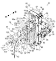
- FIG. 3 is a perspective view showing a puncture unit according to Embodiment 1.
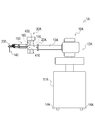
- the puncture robot 1 As shown in FIG. 1, the puncture robot 1 according to the first embodiment includes a robot body 10 and a puncture section 30 attached to a moving end 20 that moves in an arbitrary direction included in the robot body 10. is there.
- the puncture unit 30 is a part that becomes a hand portion of the robot body 10.
- the robot body 10 includes a rectangular parallelepiped housing 11, a drive unit 12 disposed on the top of the housing 11, and a horizontal end mounted on one end of the drive unit 12, and the front end side of the housing unit 11.
- the connecting rod 13 is mainly provided outside.
- a handle portion (not shown) is provided at the upper end of the side surface of the housing portion 11, and a plurality of casters 14 are provided on the bottom surface portion of the housing portion 11, so that the user moves the robot body 10 while holding the handle portion. It is free.
- the drive unit 12 is a part for moving the flange-shaped moving end 20 provided at the tip of the connecting rod 13 in a three-dimensional manner in the forward / backward direction, the up / down direction (up / down direction), and the left / right direction by a plurality of actuators (not shown). .
- the robot body 10 moves the moving end 20 in the forward / backward direction and the movement in the up / down direction and the left / right direction by a linear motion joint.
- the drive unit 12 can rotate the connecting rod 13 around the axis of the connecting rod 13A by an actuator (not shown).
- the robot body 10 drives the drive unit 12 to move the puncture unit 30 attached to the moving end 20 provided at the tip of the connecting rod 13 to a desired position.
- the robot body 10 moves the puncture unit 30 in the forward / backward direction, the up / down direction, and the left / right direction by operating the linear motion joint, thereby stabilizing the puncture unit 30 even in a narrow space such as the vicinity of a CT gantry. Can be moved in a simple orbit.
- a puncture unit 30 is attached to the moving end 20 disposed at the tip of the connecting rod 13.
- the double arrow direction shown in FIGS. 2 and 3 is the front-rear direction.
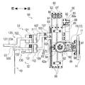
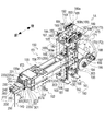
- the puncture unit 30 includes an arm unit 50 with a puncture needle 40 attached to the tip, a frame unit 60 with a base end of the arm unit 50, and a base that supports the frame unit 60. Part 70 and fixedly attached to the moving end 20 of the connecting rod 13 via the base part 70. Therefore, when the connecting rod 13 is rotated around the axis by a connecting rod rotating actuator (not shown) of the robot body 10, the puncture unit 30 rotates about the connecting rod 13 as a rotation axis.
- the base portion 70 extends from the left and right ends of the base end plate 71 toward the front, respectively, by rotating the frame portion 60 by attaching a disc-shaped base end plate 71 to which the moving end 20 at the front end of the connecting rod 13 is mounted.
- the flat plate-like first support piece 72 and the second support piece 73 that are movably supported are substantially U-shaped in plan view.
- a guide portion 74 for attaching the distal end of the connecting rod 13 is provided on the rear side of the base end plate 71, and the distal end surface of the flange-shaped moving end portion 20 is positioned by attaching and positioning the distal end of the connecting rod 13 to the guide portion 74.
- the puncture part 30 is fixed to the tip of the moving end part 20 by attaching a clamp screw.
- a frame part rotation motor 75 for rotating the frame part 60 is attached to the front side of the base end plate 71 as will be described later.
- the frame portion 60 has a rectangular frame shape, and includes a first frame 61 and a second frame 62 each provided with an advancing / retracting shaft 64 (for example, a screw shaft of a ball screw) extending in the vertical direction on the inside, and the first frame.
- a plurality of connecting rods 63 are provided to connect 61 and the second frame 62 so as to face each other. In particular, by connecting the first frame 61 and the second frame 62 with a connecting rod 63, a parallel link is configured.
- the first frame 61 and the second frame 62 have the same structure, and the first frame 61 will be described as a representative.
- the first frame 61 extends in the vertical direction and faces the plate-like first side wall 65 and the second side wall 66, and a plate-like third side connecting the upper side edges of the first side wall 65 and the second side wall 66.
- the side wall 67 and the flat fourth side wall 68 that connects the lower side edges of the first side wall 65 and the second side wall 66 form a vertically long rectangular frame.
- an intermediate wall 69 is installed between the first side wall 65 and the second side wall 66 near the third side wall 67.
- the fourth side wall 68 and the intermediate wall 69 are provided with a lower bearing 81 and an upper bearing 82 that support an advancing / retracting shaft 64 extending in the vertical direction in parallel with the first side wall 65 and the second side wall 66, and the advancing / retracting shaft 64. Is mounted so that it can rotate freely.
- advance / retreat shaft 64 protrudes upward from the upper bearing 82 and extends, and a first bevel gear 83 is attached to the upper end of the advance / retreat shaft 64 protruding upward.
- the second bevel gear 84 that meshes with the first bevel gear 83 is mounted on a rotary shaft 85 that is disposed on the first side wall 65 and the second side wall 66 so as to be rotatable on the upper side of the first bevel gear 83. ing.
- the rotation shaft 85 has the end on the second side wall 66 side extended and protruded outward, and an interlocking pulley 86 is attached to the protruding rotation shaft 85.
- the interlocking pulley 86 of the first frame 61 and the interlocking pulley 86 of the second frame 62 are pulleys of the same shape and are interlocked and connected via an interlocking timing belt 87.
- a support plate 88 for mounting the rotation shaft drive motor 89 is mounted on the intermediate wall 69 of the first frame 61, and the rotation shaft drive motor 89 is mounted on the support plate 88.
- the rotation shaft drive motor 89 is mounted with the output shaft 89a extending vertically.
- the output shaft 89a of the rotation shaft drive motor 89 is attached with an advance / retreat shaft drive pulley 90, and the advance / retreat shaft driven pulley 91 is attached to the advance / retreat shaft 64 of the first frame 61.
- the pulley 90 and the advancing / retracting shaft driven pulley 91 are interlocked with each other by an advancing / retracting shaft timing belt 92.
- the forward / backward driven pulley 91 is mounted between the first bevel gear 83 provided on the forward / backward shaft 64 of the first frame 61 and the intermediate wall 69 of the first frame 61.
- the rotation shaft drive motor 89 is driven to rotate the advance / retreat shaft 64 of the first frame 61 via the advance / retreat axis timing belt 92, and further, interlocked via the interlocking timing belt 87.
- the advance / retreat shaft 64 of the connected second frame 62 is rotated similarly to the advance / retreat shaft 64 of the first frame 61.
- the first frame 61 and the second frame 62 of the frame portion 60 are provided with pivots 93 and 94 projecting outward on the outer surfaces of the first side wall 65 and the second side wall 66, respectively.
- 94 is supported by a bearing 95 provided at a predetermined position of the first support piece 72 and the second support piece 73 of the base portion 70. That is, the first frame 61 and the second frame 62 of the frame part 60 are rotatable with respect to the base part 70.
- pivot 94 provided on the second side wall 66 side of the first frame 61 protrudes outward from the first support piece 72 of the base portion 70 and is attached with a follower pulley 96 for the frame portion.
- the frame portion driven pulley 96 includes a frame portion drive pulley 98 mounted on an output shaft 97 of a frame portion rotation motor 75 provided on the front side of the base end plate 71 of the base portion 70, and a rotation operation timing belt 99.
- the first frame 61 is rotated by the frame portion rotating motor 75 and the second frame 62 connected to the first frame 61 is rotated via the connecting rod 63. .
- the arm unit 50 includes an upper arm 51 that supports the proximal end side of the puncture needle 40 and a lower arm 52 that supports the distal end side of the puncture needle 40 relative to the upper arm 51, and the advancing / retracting axis of the frame unit 60.
- the puncture needle 40 can be mounted in parallel with the puncture needle 64.
- the upper arm 51 is mainly composed of an upper connecting body 101 having a U-shape in plan view, which will be described later, an upper left intermediate piece 107, an upper left intermediate piece 108, a first sensor 111, and an upper tip arm portion 120. ing.
- the upper arm 51 supports the proximal end side of the puncture needle 40 via a socket 53 described later.
- the lower arm 52 includes a lower connecting body 103 having a U-shape in plan view, a lower left intermediate piece 109, a lower right intermediate piece 110, a second sensor 112, and a lower tip arm section 130, which will be described later. Consists mainly of.
- the lower arm 52 supports the distal end side of the puncture needle 40 rather than the portion where the upper arm 51 supports the socket 53.
- a substantially rectangular parallelepiped socket 53 for detachably fixing the puncture needle 40 is provided in the vicinity of the distal end of the upper arm 51 that supports the puncture needle 40 and the distal end of the lower arm 52.
- the socket 53 can be detached from the upper arm 51 and the lower arm 52 by opening the upper arm 51 and the lower arm 52 to the left and right, respectively.
- the socket 53 to which the puncture needle 40 is fixed is attached to the arm portion as necessary.
- the puncture needle 40 can be quickly removed from the arm portion 50 by being removed from the arm portion 50. That is, in the state where the puncture needle 40 is punctured with respect to the patient, the puncture needle 40 can be removed manually even if it is necessary to urgently remove the puncture needle 40.
- the shape of the socket is not limited to this embodiment, and may be determined as appropriate in accordance with the shape of various puncture needles.
- the upper arm 51 and the lower arm 52 are attached to the frame portion 60 at the base end side.
- the upper moving body 100 screwed to the advance / retreat shaft 64 of the first frame 61 of the frame portion 60 and the upper side screwed to the advance / retreat shaft 64 of the second frame 62 are provided on the proximal end side of the upper arm 51.
- An upper connecting body 101 having a U-shape in plan view that is integrally connected to the moving body 100 is provided, and the base end side of the upper arm 51 is attached to the frame portion 60 via the upper connecting body 101.
- the lower moving body 102 screwed to the advance / retreat shaft 64 of the first frame 61 of the frame portion 60 and the lower mover screwed to the advance / retreat shaft 64 of the second frame 62 are provided on the base end side of the lower arm 52.
- the advancing / retracting shaft 64 and the upper moving body 100, and the advancing / retreating shaft 64 and the lower moving body 102 constitute a ball screw mechanism, respectively, and drive the rotating shaft drive motor 89 to drive the advancing / retracting shaft timing belt 92.
- the position of the upper moving body 100 and the lower moving body 102 on the advance / retreat axis 64 can be changed by rotating the advance / retreat axis 64 of the first frame 61 and the advance / retreat axis 64 of the second frame 62. That is, the puncture needle 40 is moved in the puncture direction by moving the upper arm 51 and the lower arm 52 along the advance / retreat axis 64 by driving the rotation shaft drive motor 89 by such a ball screw mechanism. Puncture can be performed by moving forward and backward.
- the upper connection body 101 and the lower connection body 103 have the same structure, and the upper connection body 101 will be described as a representative.
- the upper connecting body 101 includes a left frame 104 attached to the left side surface of the upper moving body 100 that is screwed to the advance and retreat shafts 64 of the first frame 61 and the second frame 62, and the first frame 61 and the second frame 62.
- Each of the right frame 105 attached to the right side surface of the upper movable body 100 screwed to the advance / retreat shaft 64 and the connecting frame 106 that connects the rear ends of the left frame 104 and the right frame 105 are integrally configured.
- the upper coupling body 101 includes coupling pieces 104a and 105a in which the puncture needle 40 side edges of the left frame 104 and the right frame 105 are projected to the puncture needle 40 side.
- the left frame 104 and each upper moving body 100 are connected via appropriate bearings, and the right frame 105 and each upper moving body 100 are also connected via appropriate bearings.
- a linear guide is attached to the second frame 62. That is, as shown in FIG. 3, a flat linear guide arrangement part 62a protruding forward is provided on the front side of the second frame 62, and the linear guide is arranged on the rear surface of the linear guide arrangement part 62a in parallel with the advance / retreat shaft 64.
- the rail 62b is disposed, and a slider 62c that slides along the rail 62b is integrally connected to the upper moving body 100 and the lower moving body 102.
- the upper moving body 100 and the lower moving body 102 can move in a stable path parallel to the advance / retreat axis 64, and vibrations of the upper mover 100 and the lower mover 102 moving along the advance / retreat axis 64 can be detected. Can be suppressed.
- the upper arm 51 connects the upper left intermediate piece 107 having a predetermined length to the connecting piece 104a of the left frame 104 of the upper connecting body 101, and also connects the upper left intermediate piece 107 of the predetermined length to the connecting piece 105a of the right frame 105 of the upper connecting body 101.
- the right intermediate piece 108 is connected.
- the upper left intermediate piece 107 and the upper right intermediate piece 108 are bent in a crank shape to bend the upper arm 51 and offset the puncture needle 40 in the puncture direction.
- the lower arm 52 connects the lower left intermediate piece 109 of a predetermined length to the connecting piece 104a of the left frame 104 of the lower connecting body 103, and the connecting piece of the right frame 105 of the lower connecting body 103.
- a lower right intermediate piece 110 having a predetermined length is connected to 105a.
- the lower left intermediate piece 109 and the lower right intermediate piece 110 are bent in a crank shape to bend the lower arm 52 and offset the puncture needle 40 in the puncture direction.
- the upper arm 51 and the lower arm 52 are bent in a crank shape, and the puncture needle 40 is offset in the puncture direction, so that the frame portion 60 and the base portion 70 of the puncture portion 30 are brought into contact with the patient. Therefore, it is possible to puncture the needle up to the root of the puncture needle 40.
- the upper arm 51 is provided with a first sensor 111 including a six-axis force sensor in the middle.
- the lower arm 52 is provided with a second sensor 112 including a six-axis force sensor in the middle.
- the upper left intermediate piece 107 and the upper right intermediate piece 108 are integrally connected to a holding plate that holds the rear end side of the first sensor 111, and the upper tip arm portion is interposed via the first sensor 111.
- the lower left intermediate piece 109 and the lower right intermediate piece 110 are integrally connected to a holding plate that holds the rear end side of the second sensor 112, and the lower tip arm portion 130 is connected to the lower sensor piece via the second sensor 112. It is connected.
- the first sensor 111 and the second sensor 112 are provided at the same position in the vertical direction in the initial posture where the frame portion 60 is not inclined.
- the first sensor 111 and the second sensor 112 detect the stress generated in the upper arm 51 and the lower arm 52, and puncture is interrupted when the detected amount exceeds a predetermined threshold.
- the first sensor 111 and the second sensor 112 are electrically connected to a control device described later.
- the first sensor 111 and the second sensor 112 are disposed at positions that do not enter the CT gantry in the arm unit 50, for example, in order to prevent artifacts due to metal members when working near the CT gantry. It is preferable to do.
- the upper end arm portion 120 includes a base 121 connected to the front side of the first sensor 111, a pair of left and right upper arm pieces 122 and 122 extending forward from the left and right ends of the base 121, and a socket gripping portion. 123 is mainly provided.
- the upper end arm portion 120 is formed of a resin material including the clamp screw 127 and the like.
- the pair of upper arm pieces 122 and 122 are bent in a crank shape to bend the upper arm 51 and offset the puncture needle 40 in the puncture direction.
- the rear ends of the pair of upper arm pieces 122 and 122 are pivotally supported at both the left and right ends of the base 121, and the front end sides of the upper arm pieces 122 and 122 can be opened in the horizontal direction.
- the upper arm pieces 122 and 122 are integrally connected by being fixed with a clamp screw 127 in a state in which the distal ends are locked to each other.
- the socket holding portion 123 is provided in the vicinity of the rear end side of the upper connecting arm pieces 124 and 124, and extends from the opposing surfaces of the upper arm pieces 122 and 122 to support the left and right side surfaces of the socket 53. 125/125.
- the socket holding arm pieces 125 and 125 have engaging convex portions 126 and 126 that engage with engaging concave portions 53 a and 53 a that are formed on the upper sides of the left and right side surfaces of the socket 53 at the respective ends.
- the socket holding arm pieces 125 and 125 are engaged with the engaging concave portions 53a and 53a by the engaging convex portions 126 and 126, and hold the socket 53 rotatably with respect to the socket holding arm pieces 125 and 125.
- the base end side of 53 is gripped.
- the clamp screw 127 is removed and the distal ends of the upper arm pieces 122 and 122 are opened to the left and right, the engaging projections 126 and 126 of the socket holding arm pieces 125 and 125 are disengaged from the engaging recesses 53a and 53a.
- the state in which the proximal side is gripped is released.
- the lower end arm portion 130 includes a base portion 131 connected to the front side of the second sensor 112, and a pair of left and right lower arm pieces 132 and 132 horizontally extending forward from the left and right ends of the base portion 131, respectively.
- the socket gripper 133 is mainly provided.
- the lower end arm portion 130 is formed of a resin material including the clamp screw 137 and the like.
- the rear ends of the pair of lower arm pieces 132 and 132 are pivotally supported at both the left and right ends of the base 131, and the respective distal end sides of the lower arm pieces 132 and 132 can be opened in the horizontal direction.
- a pair of lower connection arm pieces 134 that extend from the opposing surfaces of the lower arm pieces 132, 132 and connect the lower arm pieces 132, 132 to each other.
- -It has 134.
- the lower arm pieces 132 and 132 are integrally connected by being fixed with a clamp screw 137 in a state in which the distal ends are locked to each other.
- the socket gripping part 133 is provided at the tip of the lower arm pieces 132 and 132 and extends from the opposing surfaces of the lower arm pieces 132 and 132 to support the left and right side surfaces of the socket 53. have.
- the socket holding arm pieces 135 and 135 have engaging convex portions 136 and 136 that engage with engaging concave portions 53b and 53b drilled on the lower sides of the left and right side surfaces of the socket 53 at the respective tips.
- the socket holding arm pieces 135 and 135 have the engaging projections 136 and 136 engaged with the engaging recesses 53b and 53b, and the socket 53 is rotatably held with respect to the socket holding arm pieces 135 and 135.
- the front end side of 53 is gripped.
- the socket 53 has a substantially rectangular parallelepiped shape and is formed of a resin material.
- the socket 53 can be divided into right and left at the center in the left-right direction, and a fitting hole for fitting the proximal end portion of the puncture needle 40 is formed on the inner side surface.
- the engagement convex portions 126 and 126 of the socket holding arm pieces 125 and 125 engage with the engagement concave portions 53a and 53a in a state where the proximal end portion of the puncture needle 40 is fitted into the fitting hole.
- the proximal end side of the puncture needle 40 is held by the engagement convex portions 136 and 136 of the socket holding arm pieces 135 and 135 being engaged with the engagement concave portions 53b and 53b.
- the puncture needle 40 is a biopsy needle used to puncture a subject under X-ray fluoroscopy by CT to collect and inspect a tissue.
- the puncture needle 40 has an inner needle whose tip is bowl-shaped and a tubular needle tube portion that houses the inner needle.
- the puncture needle 40 collects tissue by inserting and removing the inner needle from the tip of the needle tube portion.
- the puncture needle is not limited to the present embodiment, and may be a puncture needle for other uses such as a puncture needle for radio wave therapy.
- the upper arm 51 and the lower arm 52 can be configured to extend the distance between the frame portion 60 and the puncture needle 40 by interposing an extending member in the middle portion as necessary.
- the puncture robot 1 has a control device (for example, a PC (personal computer)) for controlling the puncture robot 1 in the robot main body 10, and each actuator in the robot main body 10 and the puncture unit 30 are controlled by this control device.
- a rotation shaft drive motor 89 for rotating the advancing / retracting shaft 64 provided on the frame portion 60 and a frame portion rotation motor 75 for rotating the first frame 61 provided on the base portion 70 of the puncture portion 30 are operated. Can be made.
- the puncture robot 1 operates in accordance with the operation instruction when an operator who performs the puncture operation is instructed by an operation tool (controller) electrically connected to the PC. Further, the control device of the puncture robot 1 can acquire detection signals from the first sensor 111 and the second sensor 112 and measure the puncture force when the puncture needle 40 is punctured.
- the puncture unit 30 can be moved to a desired position by driving the robot body 10. Thereby, the position of puncture by the puncture needle 40 can be adjusted. Further, by driving the connecting rod actuator of the robot body 10, the puncture unit 30 can be rotated about the connecting rod 13 as a rotation axis. Further, the frame portion rotation motor 75 for rotating the first frame 61 provided on the base portion 70 of the puncture portion 30 enables the posture change movement of the puncture needle 40 in the biaxial direction, thereby changing the puncture angle by the puncture needle 40. Adjustable.
- the frame portion 60 is swung around the pivot 94 by driving the frame portion rotation motor 75, and the frame portion 60 is inclined, and the link is made via the frame portion 60.
- the socket 53 that holds the puncture needle 40 is rotated by the operation of the upper arm 51 and the lower arm 52, and the puncture needle 40 is tilted at the same angle as the frame section 60 is tilted. That is, the posture of the puncture needle 40 can be changed with the needle axis on the proximal end side of the puncture needle 40 as the center of rotation. Thereby, for example, the posture of the puncture needle 40 can be changed in a narrow space inside the CT gantry, and the operability of the puncture robot 1 is improved.
- the rotation shaft drive motor 89 for moving the puncture needle 40 forward and backward, and the frame portion rotation motor 75 for changing the rotation center of the posture of the puncture needle 40 is the structure arrange
- portions of the upper arm 51 and the lower arm 52 that constitute the front side (the puncture needle 40 side) of the first sensor 111 and the second sensor 112 (excluding the puncture needle 40). Is formed of a resin material.
- the puncture operation of the puncture needle 40 is performed by the rotation shaft drive motor 89, and the operation of changing the inclination of the puncture needle 40 is performed by the frame portion rotation motor 75. Operations can be performed independently.
- the first sensor 111 including a six-axis force sensor is provided in the middle of the upper arm 51
- the second sensor 112 including the six-axis force sensor is provided in the middle of the lower arm 52. Is provided.
- the detection signals of the first sensor 111 and the second sensor 112 can be acquired, and the puncture force when puncturing the puncture needle 40 can be measured.
- the first sensor 111 and the second sensor 112 for measuring the force at the time of puncturing can be arranged as close as possible to the puncture needle 40 and outside the CT gantry. As a result, it can be applied to the design of an interface for monitoring the puncture state and improving the remote operability by presenting the puncture force to the practitioner.
- the upper arm 51 and the lower arm 52 are bent in a crank shape, and the puncture needle 40 is offset in the puncture direction.
- the movable range of the puncture needle 40 is set further below the movable range of the upper movable body 100 and the lower movable body 100 on the advance / retreat shaft 64 so that the puncture to the root of the puncture needle 40 is possible. Yes.
- the puncture robot 1 of the present embodiment can perform puncture work in the vicinity of the CT gantry that irradiates X-rays on behalf of the practitioner, and can prevent the practitioner from being exposed to X-rays.
- the puncture needle 40 can be moved in the puncture direction as quickly as possible while suppressing the vibration generated in the puncture needle 40 by arranging the linear guide in the frame portion 60. Thereby, the precision at the time of puncture work improves.
- the puncture robot 1A according to the second embodiment includes a robot body 10A and a puncture section 30A attached to a moving end 20A included in the robot body 10A.
- Puncturing part 30A is a part which becomes a hand part of robot main part 10A.
- the robot main body 10A includes a rectangular parallelepiped housing portion 11A, a driving portion 12A disposed on the upper portion of the housing portion 11A, and is mounted horizontally on one end of the driving portion 12A so that the distal end is the housing portion 11A.
- the connecting rod 13A is mainly provided outside.
- the casing 11A is electrically connected to a second casing (not shown) that houses the control device by wiring.
- a handle portion (not shown) is provided at the upper end of the side surface of the housing portion 11A, and the bottom surface portion of the housing portion 11A has a plurality of casters 14A, and the user moves the robot body 10A by gripping the handle portion. It is free.
- the drive unit 12A is a portion for moving the flange-shaped moving end 20A provided at the tip of the connecting rod 13A by a plurality of actuators (not shown) in a three-dimensional manner in the forward / backward direction, the vertical direction (lifting direction), and the horizontal direction. .
- the robot body 10 ⁇ / b> A operates the linear movement joint to move the moving end 20 ⁇ / b> A in the forward / backward direction and in the vertical and horizontal directions.
- the drive unit 12A can rotate the connecting rod 13A around the axis of the connecting rod 13A by an actuator (not shown).
- robot main bodies drive the drive part 12A, and can move the puncture part 30A with which the moving end part 20A provided in the front-end
- the robot body 10A moves the puncture unit 30A in the forward / backward direction, the up / down direction, and the left / right direction by operating the linear motion joint, thereby stabilizing the puncture unit 30A even in a narrow space such as the vicinity of the CT gantry. Can be moved in a simple orbit.
- a puncture portion 30A is attached to the moving end 20A disposed at the tip of the connecting rod 13A.
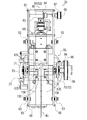
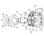
- the puncture portion 30A includes an arm portion 150 with a puncture needle 140 attached to the distal end, a frame portion 160 (see FIG. 9) with a proximal end of the arm portion 150, and this frame. 9 includes a base part 170 (see FIG. 9) that supports the part 160, a frame cover 400 that covers the frame part 160, and a base cover 410 that covers the base part 170. It is fixedly attached to the moving end 20A. Therefore, when the connecting rod 13A is rotated around the axis by a connecting rod rotating actuator (not shown) of the robot body 10A, the puncture portion 30A rotates about the connecting rod 13A as a rotation axis. 9 and the like show a state where the frame cover 400 and the base cover 410 are removed in order to show the detailed structure of the puncture portion 30A.
- the base portion 170 extends from the left and right ends of the base end plate 171 to which the moving end portion 20A at the distal end of the connecting rod 13A is attached and the left and right ends of the base end plate 171 forward to rotate the frame portion 160.
- the flat plate-like first support piece 172 and second support piece 173 that are movably supported are substantially U-shaped in plan view.
- a guide portion 174 for attaching the tip of the connecting rod 13 is provided on the rear side of the base end plate 171, and the tip of the connecting rod 13A is attached to the guide portion 174 for positioning, and the rear end face of the flange-shaped moving end 20A
- a puncture portion 30A is fixed to the distal end of the moving end portion 20A by attaching a clamp screw.
- a frame portion rotation motor 175 for rotating the frame portion 160 is attached to the front side of the base end plate 171 as will be described later.
- the frame portion 160 has a rectangular frame shape, and includes a first frame 161 and a second frame 162 each provided with an advancing / retreating shaft 164 (for example, a screw shaft of a ball screw) extending in the vertical direction on the inside, and the first frame 161 and the second frame 162 are provided with a plurality of connecting rods 163 that are opposed to each other.
- a parallel link is configured by connecting the first frame 161 and the second frame 162 with a connecting rod 163.
- the first frame 161 and the second frame 162 have the same structure, and the first frame 161 will be described as a representative.
- the first frame 161 extends in the up-down direction and faces the flat first side walls 165 and second side walls 166, and the third flat plate shape that connects the upper side edges of the first side wall 165 and the second side wall 166.
- the side wall 167 and the flat fourth side wall 168 connecting the lower side edges of the first side wall 165 and the second side wall 166 form a vertically long rectangular frame.
- the third side wall 167 and the fourth side wall 168 are provided with a lower bearing 181 and an upper bearing 182 that support an advancing / retracting shaft 164 extending in the vertical direction in parallel with the first side wall 165 and the second side wall 166, so 164 is rotatably mounted.
- the advance / retreat shaft 164 is extended upward and protrudes from the upper bearing 182, and a first bevel gear 183 is attached to the upper end of the advance / retreat shaft 164 protruding upward.
- the frame portion 160 has an upper frame portion 169 having a rectangular shape in a side view so as to surround the first bevel gear 183 on the upper portion of the third side wall 167.
- the second bevel gear 184 that meshes with the first bevel gear 183 is rotatably installed on the first upper side wall 169a and the second upper side wall 169b of the upper frame portion 169 on the upper side of the first bevel gear 183.
- the rotary shaft 185 is attached.
- the rotation shaft 185 has an end portion on the first upper side wall 169a side extended and protruded outward, and an interlocking pulley 186 is attached to one end of the protruding rotation shaft 185.
- the interlocking pulley 186 of the first frame 161 and the interlocking pulley 186 of the second frame 162 are pulleys having the same shape, and are interlocked and connected via an interlocking timing belt 187.
- a support plate 188 for mounting the rotation shaft drive motor 189 is mounted on the second upper side wall 169b of the upper frame portion 169, and the rotation shaft drive motor is mounted on the support plate 188.
- the output shaft 189a of 189 is extended in the horizontal direction, and the drive motor 189 for the rotation shaft is attached.
- the output shaft 189a of the rotation shaft drive motor 189 is mounted with the forward / backward shaft drive pulley 190, and the forward / backward shaft 164 of the first frame 161 is mounted with the forward / backward shaft driven pulley 191.
- the pulley 190 and the advancing / retracting shaft driven pulley 191 are interlocked with each other by the advancing / retreating shaft timing belt 192.
- the advancing / retracting shaft driven pulley 191 is attached to the other end of the rotating shaft 185.
- the rotation axis drive motor 189 is driven to rotate the advance / retreat axis 164 of the first frame 161 via the advance / retreat axis timing belt 192, and further, interlocked via the interlocking timing belt 187.
- the advance / retreat shaft 164 of the connected second frame 162 is rotated in the same manner as the advance / retreat shaft 164 of the first frame 161.
- the first frame 161 and the second frame 162 of the frame portion 160 are provided with pivots 193 and 194 protruding outward on the outer surfaces of the first side wall 165 and the second side wall 166, respectively.
- 194 is pivotally supported by a bearing 195 provided at a predetermined position of the first support piece 172 and the second support piece 173 of the base portion 170. That is, the first frame 161 and the second frame 162 of the frame portion 160 are rotatable with respect to the base portion 170.
- a pivot 194 provided on the second side wall 166 side of the first frame 161 is protruded outward from the first support piece 172 of the base portion 170, and a frame portion driven pulley 196 is mounted.
- the frame portion driven pulley 196 includes a frame portion driving pulley 198 mounted on the output shaft 197 of the frame portion rotation motor 175 provided on the front side of the base end plate 171 of the base portion 170, and a rotation operation timing belt 199.
- the first frame 161 is rotated by the frame portion rotating motor 175 and the second frame 162 connected to the first frame 161 is rotated by the connecting rod 163. .
- the arm unit 150 has a square tube shape at the tip and supports a sensor holding unit 153 that holds the sensor inside.
- the arm unit 150 includes an upper arm 151 that supports the front upper end of the sensor holding unit 153, a lower arm 152 that supports the front lower end of the sensor holding unit 153, a sensor holding unit 153, and an air cylinder. 220 and a needle gripping portion 230 are mainly provided.
- the upper arm 151 mainly includes an upper arm base portion 154 having a rectangular shape in plan view, and an upper arm tip portion 155 having a U shape in plan view connected to the front end of the upper arm base portion 154.
- an upper arm tip portion 155 having a U shape in plan view connected to the front end of the upper arm base portion 154.
- the lower arm 152 mainly includes a lower arm base portion 156 having a rectangular shape in plan view, and a lower arm tip portion 157 having a U-shape in plan view connected to the front end of the lower arm base portion 156.
- the base end side of the upper arm 151 and the lower arm 152 is attached to the frame portion 160.
- the upper part of the vertically long first moving body 200 screwed to the advance / retreat shaft 164 of the first frame 161 of the frame part 160 and the advance / retreat of the second frame 162 are provided on the base end side of the upper arm 151.
- An upper connecting body 201 integrally connected to the upper portion of the vertically long second movable body 200 screwed to the shaft 164 is provided, and the base end side of the upper arm 151 is connected to the frame portion 160 via the upper connecting body 201. It is attached to.
- the lower side portion of the first moving body 200 screwed to the advance / retreat shaft 164 of the first frame 161 of the frame portion 160 and the advance / retreat shaft 164 of the second frame 162 are provided on the base end side of the lower arm 152.
- a lower connecting body 203 that integrally connects the lower part of the second movable body 200 screwed together is provided, and the base end side of the lower arm 152 is attached to the frame portion 160 via the lower connecting body 203. Yes.
- the advancing / retracting shaft 164 and the first moving body 200 of the first frame 161 and the advancing / retreating shaft 164 and the second moving body 200 of the second frame 162 constitute a ball screw mechanism, respectively, and drive the rotation shaft drive motor 189.
- the advance / retreat axis 164 of the first frame 161 and the advance / retreat axis 164 of the second frame 162 are rotated via the advance / retreat axis timing belt 192, and the advance / retreat axes 164 of the first moving body 200 and the second moving body 200 are rotated.
- the upper position can be changed.
- the puncture needle 140 is moved in the puncture direction by driving the rotary shaft drive motor 189 and moving the upper arm 151 and the lower arm 152 forward and backward along the advance / retreat axis 164 by such a ball screw mechanism. Puncture can be performed by moving forward and backward.
- the upper connection body 201 and the lower connection body 203 have the same structure, and the upper connection body 201 will be described as a representative.
- the upper connecting body 201 includes a left side surface of the first moving body 200 screwed to the advance / retreat shaft 164 of the first frame 161 and a left side surface side of the second moving body 200 screwed to the advance / retreat shaft 164 of the second frame 162.
- the left frame 204, the first moving body 200, and the second moving body 200 are connected via appropriate bearings
- the right frame 205, the first moving body 200, and the second moving body 200 are also appropriate. They are connected via bearings.
- linear guides are attached to the first frame 161 and the second frame 162. That is, as shown in FIG. 10, flat linear guide arrangement portions 161a and 162a projecting rearward are provided on the rear sides of the first frame 161 and the second frame 162, respectively, and the linear guide arrangement portions 161a,
- the linear guide rails 161b and 162b are arranged on the front surface of 162a in parallel with the advancing and retracting shaft 164, and the sliders 161c and 162c sliding along the rails 161b and 162b are the first moving body 200, the second moving body 200, and the like. They are connected together.
- the first moving body 200 and the second moving body 200 can move in a stable path parallel to the advance / retreat axis 164, and the first mover 200 and the second mover 200 move along the advance / retreat axis 164. Vibration can be suppressed.
- an upper sensor 211 and a lower sensor 212 made of a six-axis force sensor are arranged in a vertically stacked state.
- the lower sensor 212 is fixed to the bottom inside the sensor holding portion 153 and is connected to the upper portion of the lower sensor 212 in a state where the upper sensor 211 is placed.
- One end of a support plate 221 for supporting the air cylinder 220 is fixed to the upper end surface of the upper sensor 211.
- the other end of the support plate 221 extends to the outside of the sensor holding portion 153 and protrudes forward.
- One end side (upper end side in FIG.
- an air cylinder main body 220 a that is a main body portion of the air cylinder 220 is connected to the lower surface of the other end of the support plate 221.
- the upper sensor 211 and the lower sensor 212 are connected to the needle gripping part 230 via the support plate 221 and the air cylinder 220.
- the air cylinder 220 has a substantially rectangular parallelepiped shape and is a pneumatically driven linear actuator.
- the air cylinder 220 is attached to the air cylinder main body 220a that is the main body portion of the air cylinder 220, the piston rod 220b (see FIG. 10) that is housed in the air cylinder main body 220a, and advances and retreats at a predetermined stroke, and the tip of the piston rod 220b.
- a plate-like blade 220c is provided.
- the air cylinder 220 instantaneously advances / retreats with a predetermined stroke along the forward / backward direction of the piston rod 220b (vertical direction in the state of FIG. 10) by the air pressure of the supplied air (advance operation at the time of puncture) )
- the upper sensor 211 and the lower sensor 212 detect the stress generated in the needle gripping part 230 via the support plate 221 and the air cylinder 220, and puncture is interrupted when the detected amount exceeds a predetermined threshold.
- the upper sensor 211 and the lower sensor 212 are electrically connected to a control device described later.
- the upper sensor 211 and the lower sensor 212 are connected in series and arranged in series. By configuring in this way, it is possible to detect the stress generated in the needle gripping portion 230 by the upper sensor 211 and the lower sensor 212 at the same time. Further, even if one of the upper sensor 211 and the lower sensor 212 fails, the stress generated in the needle gripping portion 230 can be detected by the other sensor.
- the upper sensor 211 and the lower sensor 212 are disposed at a position that does not enter the CT gantry in the arm unit 150, for example, in order to prevent the occurrence of artifacts due to metal members when working near the CT gantry. Is preferred.
- the needle gripping portion 230 is attached to the blade 220c of the air cylinder 220 via an air cylinder fixture 300 that is a fixing jig for fixing the needle gripping portion 230 to the air cylinder 220.
- the air cylinder fixture 300 has a plate-like contact fixing portion 301 that is fixed in contact with the surface of the blade 220c (the lower surface in the state of FIG. 10), and a front protrusion adjacent to the contact fixing portion 301. It has a substantially rectangular parallelepiped fitting portion 302 that is formed in a shape and fits into the fitted portion 241 of the needle gripping portion 230 (needle gripping arm fixture 240).
- the fitting portion 302 is provided with a through hole into which a fixing pin 231 described later can be inserted.
- the needle gripping part 230 has a needle gripping arm fixture 240, a pair of needle gripping arms 250, and a plurality (two in this embodiment) of fixing pins 231.
- the needle gripping arm fixture 240 is a resin member having an H-shape when viewed from the side, and is provided on the rear end side.
- the fitted portion 241 to which the fitting portion 302 of the air cylinder fixture 300 is fitted, and the front end side A rotation support portion 242 that pivotally supports each of the pair of needle gripping arms 250 (left needle gripping arm 260, right needle gripping arm 270) and pivotally supports them, and a fitted portion 241. It has a plurality of through holes 244 penetrating in the vertical direction.
- the needle gripping arm fixture 240 is attached to the air cylinder fixture 300 by inserting the fixing pin 231 described above in a state where the fitting portion 302 of the air cylinder fixture 300 is fitted to the fitted portion 241. Thereby, the needle gripping arm fixture 240 can be easily attached to and detached from the air cylinder fixture 300 attached to the air cylinder 220 by inserting and removing the fixing pin 231.
- the needle gripping arm 250 mainly includes a pair of left and right left hand gripping arms 260 and a right hand needle gripping arm 270 that extend forward, and a puncture needle holding portion 280 that holds the proximal end portion of the puncture needle 140. .
- the left needle gripping arm 260, the right needle gripping arm 270, and the puncture needle holding part 280 are made of a resin material.
- the rear ends of the left and right pair of left and right needle gripping arms 260 and 270 are pivotally supported by the left and right ends of the rotation support portion 242 of the needle gripping arm fixture 240, and the left and right needle gripping arms 260 and 270 are supported. Each of the tip ends can be rotated and opened in the horizontal direction in the range of 90 degrees.
- the puncture needle holding part 280 has a substantially rectangular parallelepiped shape, is divided into right and left at the center in the left-right direction, and is attached to the opposing concave portions of the right needle gripping arm 270 and the puncture needle holding part 280 by an attachment member.
- a fitting hole for fitting the proximal end portion of the puncture needle 140 is formed on the inner side surface of the puncture needle holding portion 280.
- a snap lock 290 is provided at the front ends of the left needle gripping arm 260 and the right needle gripping arm 270.
- the left needle gripping arm 260 and the right needle gripping arm 270 are in a state in which the proximal end portion of the puncture needle 140 is fitted into the fitting hole, and the inner side surface where the left needle gripping arm 260 and the right needle gripping arm 270 are opposed to each other.
- the proximal end side of the puncture needle 140 is held by closing the snap lock 290 and closing the snap lock 290.
- the shape of the puncture needle holding unit 280 is not limited to the present embodiment, and may be appropriately determined according to the shape of various puncture needles.
- the puncture needle holding unit 280 may be formed integrally with the left needle gripping arm 260 and the right needle gripping arm 270 instead of being separated from the left needle gripping arm 260 and the right needle gripping arm 270.
- the puncture needle 140 can be detached from the left needle gripping arm 260 and the right needle gripping arm 270 by removing the snap lock 290 and opening the left needle gripping arm 260 and the right needle gripping arm 270 to the left and right, respectively.
- the puncture needle 140 can be quickly removed from the needle gripping arm 250. That is, in the state where the puncture needle 140 is punctured with respect to the patient, the puncture needle 140 can be removed manually even if it is necessary to urgently remove the puncture needle 140.
- the puncture needle 140 is a biopsy needle that is used to puncture a subject under X-ray fluoroscopy by CT to collect and examine a tissue.
- the puncture needle 140 has an inner needle whose tip is bowl-shaped and a tubular needle tube portion that houses the inner needle.
- the puncture needle 140 collects tissue by inserting and removing the inner needle from the tip of the needle tube portion.
- the puncture needle is not limited to the present embodiment, and may be a puncture needle for other uses such as a puncture needle for radio wave therapy.
- the upper arm 151 and the lower arm 152 can be configured to extend the distance between the frame portion 160 and the puncture needle 140 by interposing an extending member in the middle portion as necessary.
- the puncture robot 1A includes a control device (for example, a PC (personal computer)) for controlling the puncture robot 1A in a second casing (not shown) that is electrically connected to the first casing 11A of the robot body 10A. And a rotation shaft drive motor 189 for rotating the advancing / retracting shaft 164 provided on the frame portion 160 of the puncture portion 30A, and the puncture portion 30A.
- the frame portion rotating motor 175 for rotating the first frame 161 provided on the base portion 170 can be operated.
- the puncture robot 1A operates according to the operation instruction when an operator who performs the puncture operation is instructed by an operation tool (controller) electrically connected to the PC.
- the control device of the puncture robot 1A can acquire detection signals from the upper sensor 211 and the lower sensor 212 and measure the puncture force when the puncture needle 140 is punctured. Further, the control device of puncture robot 1A can puncture puncture needle 140 instantaneously at the puncture site of the patient by operating air cylinder 220 in accordance with an operation instruction from the operator's operation tool. Further, the control device included in the puncture robot 1A automatically moves the moving end portion 20A in the advancing / retreating direction and moving in the up / down direction and the left / right direction by the linear motion joint by performing predetermined operation settings. Even if is operated, the tip (needle tip) of the puncture needle 140 can be prevented from moving from a predetermined three-dimensional position. This makes it easy to adjust the angle of the puncture needle 140 without moving the tip of the puncture needle 140 while the tip (needle tip) of the puncture needle 140 is close to the puncture site of the patient.
- the puncture unit 30A can be moved to a desired position by driving the robot body 10A. Thereby, the position of the puncture by the puncture needle 140 can be adjusted. Further, by driving the connecting rod actuator of the robot body 10A, the puncture portion 30A can be rotated about the connecting rod 13A as a rotation axis. Furthermore, the frame portion rotation motor 175 for rotating the first frame 161 provided on the base portion 170 of the puncture portion 30A enables the puncture angle of the puncture needle 140 to change the posture of the puncture needle 140 in the biaxial direction. Adjustable.
- the puncture robot 1A by driving the frame portion rotating motor 175, the frame portion 160 swings about the pivot 194, and the frame portion 160 is inclined, and the link is made via the frame portion 160.
- the sensor holding portion 153 is rotated by the operation of the upper arm 151 and the lower arm 152 to rotate, the puncture needle 140 integrally connected to the front end side of the sensor holding portion 153 is rotated, and the frame portion 160 is inclined.
- the puncture needle 140 is inclined at the same angle as the angle. Thereby, for example, the posture of the puncture needle 140 can be changed in a narrow space inside the CT gantry, and the operability of the puncture robot 1A is improved.
- the rotation shaft drive motor 189 for moving the puncture needle 140 forward and backward and the frame portion rotation motor 175 for changing the rotation center of the posture of the puncture needle 140 are provided.
- the configuration is arranged behind the frame portion 160. Accordingly, the rotation shaft drive motor 189 and the frame portion rotation motor 175 can be disposed outside the CT gantry during the puncturing operation under X-ray fluoroscopy by CT. Therefore, these drive motors do not affect the CT image, and the operability of the puncture robot 1A is improved.
- the puncture operation of the puncture needle 140 is performed by the rotation shaft drive motor 189, and the operation of changing the inclination of the puncture needle 140 is performed by the frame portion rotation motor 175. Operations can be performed independently.
- the upper sensor 211 and the lower sensor 212 which are six-axis force sensors, are stacked on the distal ends of the upper arm 151 and the lower arm 152 in a stacked manner. Thereby, the detection signals of the upper sensor 211 and the lower sensor 212 can be acquired, and the puncture force when puncturing the puncture needle 40 can be measured. Further, the upper sensor 211 and the lower sensor 212 for measuring the force at the time of puncturing can be arranged as close as possible to the puncture needle 140 and outside the CT gantry. As a result, it can be applied to the design of an interface for monitoring the puncture state and improving the remote operability by presenting the puncture force to the practitioner.
- the puncture robot 1A of the present embodiment can perform puncture work in the vicinity of the CT gantry that irradiates X-rays on behalf of the practitioner, and can prevent the practitioner from being exposed to X-rays.
- the puncture needle 140 can be moved in the puncture direction as soon as possible while suppressing the vibration generated in the puncture needle 140. Thereby, the precision at the time of puncture work improves.
- the puncture needle 140 since the puncture needle 140 is attached to the air cylinder 220 via the needle gripping portion 230 and the needle gripping arm fixture 240, the air cylinder 220 causes an instantaneous advance operation.
- the puncture needle 140 can be instantaneously punctured with a short stroke in the puncture direction (operation that penetrates the patient's skin).
- an instantaneous puncture operation similar to that performed when a doctor performs a puncture operation manually can be performed.
- the needle gripping portion 230 is easily attached to the distal end side (the front side of the air cylinder 220) of the upper arm 151 and the lower arm 152 using the two fixing pins 231.
- the puncture needle 140 can be easily attached / detached by opening / closing the lock of the snap lock 290 and opening / closing the left and right needle gripping arms 260 and 270 to the left and right.
- the practitioner can cleanly attach and replace the puncture needle 140, and the puncture needle 140 and its surroundings can be kept clean.
- the operator simply inserts the sterilized needle gripping portion 230 into the air cylinder fixture 300 and then inserts the fixing pin 231 to complete the attachment.
- the puncture needle 140 is sandwiched and held from both sides by the left needle gripping arm 260 and the right needle gripping arm 270. After being sandwiched and held from the left and right by the left needle gripping arm and the right needle gripping arm, the left needle gripping arm 260 and the right needle gripping arm 270 are closed and locked by the snap lock 290, and gripping of the puncture needle 140 is completed.
- it is very important to secure a clean area and to easily set up an exchange instrument such as a puncture needle. According to the puncture robot 1A of the present embodiment, these can be realized. Note that the shape of the left needle gripping arm and the right needle gripping arm can be appropriately changed depending on the type of puncture needle.
- the puncture robot of the present invention can be used when performing a medical puncture operation.
- a puncture can be performed while confirming the position of a tumor and the position of a puncture needle by performing X-ray fluoroscopy using CT or the like. Useful when doing.
Landscapes
- Health & Medical Sciences (AREA)
- Surgery (AREA)
- Life Sciences & Earth Sciences (AREA)
- Engineering & Computer Science (AREA)
- Molecular Biology (AREA)
- Public Health (AREA)
- Veterinary Medicine (AREA)
- Biomedical Technology (AREA)
- Heart & Thoracic Surgery (AREA)
- Medical Informatics (AREA)
- Nuclear Medicine, Radiotherapy & Molecular Imaging (AREA)
- Animal Behavior & Ethology (AREA)
- General Health & Medical Sciences (AREA)
- Pathology (AREA)
- Robotics (AREA)
- Oral & Maxillofacial Surgery (AREA)
- Physics & Mathematics (AREA)
- Plasma & Fusion (AREA)
- Otolaryngology (AREA)
- Manipulator (AREA)
- Apparatus For Radiation Diagnosis (AREA)
Abstract
Description
一方で、CTガントリ内に金属材料が存在すると、アーチファクトを引き起こしCT画像に悪影響を及ぼすため、針を回転させるための駆動モータやセンサを針の近傍に配置することはできない。
実施例1に係る穿刺ロボット1は、図1に示すように、ロボット本体10と、このロボット本体10が備える任意の方向に移動する移動端部20に装着される穿刺部30とを有するものである。穿刺部30は、ロボット本体10の手先部となる部分である。
なお、穿刺部30においては、図2、図3で示す両矢印方向を前後方向とする。
下側アーム52は、後述する平面視コ字状の下側連結体103と、下側左側中間片109と、下側右側中間片110と、第2センサ112と、下側先端アーム部130とから主に構成されている。下側アーム52は、上側アーム51がソケット53を支持する部分よりも穿刺針40の先端側を支持する。
なお、ソケットの形状は、本実施形態に限定するものではなく、各種穿刺針の形状に対応して適宜決定すればよい。
なお、第1センサ111と第2センサ112は、例えば、CTのガントリの近傍での作業時において、金属部材によるアーチファクトの発生を防ぐために、アーム部50においてCTのガントリ下に入らない位置に配置することが好ましい。加えて、上側アーム51及び下側アーム52を介して穿刺針40に生じる応力を精度よく検出するために、なるべく穿刺針40に近い位置に配置することが好ましい。
なお、穿刺針としては、本実施形態に限定するものではなく、例えば、ラジオ波治療用の穿刺針等のその他の用途の穿刺針であっても構わない。
次に、実施例2に係る穿刺ロボット1Aについて図を用いて説明する。
実施例2に係る穿刺ロボット1Aは、図7及び図8に示すように、ロボット本体10Aと、このロボット本体10Aが備える移動端部20Aに装着される穿刺部30Aとを有するものである。穿刺部30Aは、ロボット本体10Aの手先部となる部分である。
なお、穿刺部30Aにおいては、図9等で示す両矢印方向を前後方向とする。
なお、図9等では、穿刺部30Aの詳細な構造を示すためにフレームカバー400、ベースカバー410を取り外した状態を図示している。
また、フレーム部160は、第3側壁167の上部に、第1傘歯車183を囲うように側面視矩形状の上部フレーム部169を有している。
下側アーム152は、平面視矩形状の下側アーム基部156と、この下側アーム基部156の前端に連結される平面視コ字状の下側アーム先端部157とから主に構成されている。下側アーム先端部157の先端には、センサ保持部153の前部下端側を回動自在に軸支する一対の軸支部157aを有している。
なお、上部センサ211と下部センサ212は、例えば、CTのガントリの近傍での作業時において、金属部材によるアーチファクトの発生を防ぐために、アーム部150においてCTのガントリ下に入らない位置に配置することが好ましい。加えて、上側アーム151及び下側アーム152を介して穿刺針140に生じる応力を精度よく検出するために、なるべく穿刺針140に近い位置に配置することが好ましい。
なお、穿刺針保持部280の形状は、本実施形態に限定するものではなく、各種穿刺針の形状に対応して適宜決定すればよい。また、穿刺針保持部280は、左側針把持アーム260及び右側針把持アーム270と別体ではなく、左側針把持アーム260及び右側針把持アーム270と一体的に形成してもよい。
なお、穿刺針としては、本実施形態に限定するものではなく、例えば、ラジオ波治療用の穿刺針等のその他の用途の穿刺針であっても構わない。
30、30A 穿刺部
40、140 穿刺針
50、150 アーム部
51、151 上側アーム
52、152 下側アーム
60、160 フレーム部
61、161 第1フレーム
62、162 第2フレーム
63、163 連結桿
64、164 進退軸
70、170 ベース部
220 エアシリンダ(アクチュータ)
Claims (8)
- ロボット本体と、このロボット本体が備えた任意の方向に移動する移動端部に装着した穿刺部とを有する穿刺ロボットにおいて、
前記穿刺部は、
先端に穿刺針を装着したアーム部と、
このアーム部の基端を装着したフレーム部と、
このフレーム部を支持するベース部と
を備え、
前記フレーム部は、矩形枠状であって内側に上下方向に延伸させた進退軸をそれぞれ設けた第1フレーム及び第2フレームと、この第1フレームと第2フレームとを互いに対向させて連結する連結桿とを備え、
前記アーム部は、前記穿刺針の基端側を支持する上側アームと、この上側アームよりも前記穿刺針の先端側を支持する下側アームとを備えて、前記進退軸と平行に前記穿刺針を装着し、
前記上側アームと前記下側アームとを前記進退軸に沿って進退移動させることで前記穿刺針を穿刺方向に進退移動させる穿刺ロボット。 - 前記上側アームの中途部に6軸力センサからなる第1センサを設けるとともに、前記下側アームの中途部に6軸力センサからなる第2センサを設ける請求項1に記載の穿刺ロボット。
- 前記上側アームと前記下側アームは、クランク状に屈曲させて、前記穿刺針を穿刺方向にオフセットしている請求項2に記載の穿刺ロボット。
- 前記上側アームと前記下側アームは、前記第1センサと前記第2センサよりも穿刺針側の部分を樹脂材料で形成している請求項2または請求項3に記載の穿刺ロボット。
- ロボット本体と、このロボット本体が備えた任意の方向に移動する移動端部に装着した穿刺部とを有する穿刺ロボットにおいて、
前記穿刺部は、
先端に穿刺針を装着したアーム部と、
このアーム部の基端を装着したフレーム部と、
このフレーム部を支持するベース部と
を備え、
前記フレーム部は、矩形枠状であって内側に上下方向に延伸させた進退軸をそれぞれ設けた第1フレーム及び第2フレームと、この第1フレームと第2フレームとを互いに対向させて連結する連結桿とを備え、
前記アーム部は、前記進退軸と平行に前記穿刺針を装着するとともに、その中途部に前記穿刺針を穿刺方向に沿って進退するアクチュエータを備えて、
前記上側アームと前記下側アームとを前記進退軸に沿って進退移動させることで前記穿刺針を穿刺部位近傍に進退移動させ、
前記穿刺部位近傍における前記穿刺針の穿刺動作時に前記アクチュエータを瞬発的に駆動して前記穿刺部位に瞬発的に穿刺する穿刺ロボット。 - 前記アーム部は、その中途部に6軸力センサからなる二つのセンサを積層して設ける請求項5に記載の穿刺ロボット。
- 前記アーム部は、先端に穿刺針を把持する針把持部を有し、前記針把持部は前記アーム部に対して着脱自在である請求項5または請求項6に記載の穿刺ロボット。
- 前記針把持部は、樹脂材料で形成している請求項5から請求項7のいずれか一項に記載の穿刺ロボット。
Priority Applications (3)
| Application Number | Priority Date | Filing Date | Title |
|---|---|---|---|
| JP2017506443A JP6440177B2 (ja) | 2015-10-13 | 2016-09-29 | 穿刺ロボット |
| US15/767,855 US11096751B2 (en) | 2015-10-13 | 2016-09-29 | Puncture robot |
| US17/206,808 US20210205038A1 (en) | 2015-10-13 | 2021-03-19 | Puncture robot |
Applications Claiming Priority (2)
| Application Number | Priority Date | Filing Date | Title |
|---|---|---|---|
| JP2015202482 | 2015-10-13 | ||
| JP2015-202482 | 2015-10-13 |
Related Child Applications (2)
| Application Number | Title | Priority Date | Filing Date |
|---|---|---|---|
| US15/767,855 A-371-Of-International US11096751B2 (en) | 2015-10-13 | 2016-09-29 | Puncture robot |
| US17/206,808 Division US20210205038A1 (en) | 2015-10-13 | 2021-03-19 | Puncture robot |
Publications (1)
| Publication Number | Publication Date |
|---|---|
| WO2017065016A1 true WO2017065016A1 (ja) | 2017-04-20 |
Family
ID=58517516
Family Applications (1)
| Application Number | Title | Priority Date | Filing Date |
|---|---|---|---|
| PCT/JP2016/078920 Ceased WO2017065016A1 (ja) | 2015-10-13 | 2016-09-29 | 穿刺ロボット |
Country Status (3)
| Country | Link |
|---|---|
| US (2) | US11096751B2 (ja) |
| JP (1) | JP6440177B2 (ja) |
| WO (1) | WO2017065016A1 (ja) |
Cited By (7)
| Publication number | Priority date | Publication date | Assignee | Title |
|---|---|---|---|---|
| WO2018207498A1 (ja) * | 2017-05-09 | 2018-11-15 | 国立大学法人 岡山大学 | 穿刺ロボット及び穿刺制御用プログラム |
| CN112220537A (zh) * | 2020-10-30 | 2021-01-15 | 北京大学深圳医院 | 肾内科用穿刺辅助装置 |
| CN113229939A (zh) * | 2021-04-29 | 2021-08-10 | 江苏众远智能装备有限公司 | 一种高精穿刺协作机器人及生产方法 |
| CN113349896A (zh) * | 2021-07-07 | 2021-09-07 | 北京精准医械科技有限公司 | 一种针穿刺机构及穿刺手术机器人 |
| CN113749739A (zh) * | 2021-08-20 | 2021-12-07 | 中国人民解放军总医院 | 一种用于骨肿瘤手术穿刺定位装置及其使用方法 |
| CN114515195A (zh) * | 2022-03-18 | 2022-05-20 | 华中科技大学同济医学院附属协和医院 | 一种肺穿刺手术机器人 |
| CN114869427A (zh) * | 2022-05-19 | 2022-08-09 | 真实维度科技控股(珠海)有限公司 | 一种用于穿刺装置的俯仰微调机构及穿刺装置 |
Families Citing this family (21)
| Publication number | Priority date | Publication date | Assignee | Title |
|---|---|---|---|---|
| CN112120737A (zh) * | 2019-08-07 | 2020-12-25 | 杭州睿笛生物科技有限公司 | 一种电脉冲消融设备 |
| JP2021191382A (ja) * | 2020-06-05 | 2021-12-16 | 国立大学法人 岡山大学 | 穿刺針把持装置及びこの穿刺針把持装置を備えた穿刺ロボット |
| CN111643188B (zh) * | 2020-06-16 | 2024-07-30 | 上海交通大学 | 一种穿刺手术机器人装置 |
| CN112353461B (zh) * | 2020-10-08 | 2024-11-01 | 王洪奎 | Ct实时定位精准穿刺机器人 |
| CN112353495B (zh) * | 2020-10-29 | 2021-08-10 | 北京唯迈医疗设备有限公司 | 一种介入手术机器人手臂系统 |
| CN112168309B (zh) * | 2020-11-10 | 2022-05-27 | 哈尔滨理工大学 | 一种基于双机械手爪的柔性针穿刺机构 |
| CN112568980A (zh) * | 2020-12-15 | 2021-03-30 | 航天科工智能机器人有限责任公司 | 一种适用于不同型号规格穿刺针的夹持装置 |
| CN115500907A (zh) * | 2021-05-24 | 2022-12-23 | 武汉联影智融医疗科技有限公司 | 一种穿刺装置和穿刺系统 |
| CN113662641B (zh) * | 2021-10-25 | 2022-02-22 | 北京微刀医疗科技有限公司 | Ct引导穿刺针输送装置 |
| CN114343794A (zh) * | 2021-12-04 | 2022-04-15 | 上海术航机器人有限公司 | 对准装置、系统、方法以及计算机设备、存储介质 |
| CN115517777A (zh) * | 2022-01-29 | 2022-12-27 | 深圳市爱博医疗机器人有限公司 | 一种介入手术机器人的从端动力座 |
| CN114431938A (zh) * | 2022-02-25 | 2022-05-06 | 上海睿触科技有限公司 | 一种新型的ct引导下穿刺辅助定位装置 |
| CN114668464B (zh) * | 2022-03-29 | 2024-05-28 | 哈尔滨理工大学 | 一种柔性针自动更换装置 |
| CN114469283B (zh) * | 2022-03-31 | 2022-07-01 | 真健康(北京)医疗科技有限公司 | 连杆式四自由度穿刺针定位导向装置 |
| CN114469285B (zh) * | 2022-03-31 | 2022-07-22 | 真健康(北京)医疗科技有限公司 | 连杆式五自由度穿刺机器人 |
| CN114711920B (zh) * | 2022-04-28 | 2024-08-23 | 哈尔滨理工大学 | 一种柔性针夹紧机构 |
| CN114939884B (zh) * | 2022-06-20 | 2024-11-05 | 深圳传世生物医疗有限公司 | 一种夹持装置及穿刺加液设备 |
| CN115590589B (zh) * | 2022-10-12 | 2025-11-11 | 上海交通大学 | 一种并联六自由度穿刺机器人 |
| CN115956982B (zh) * | 2022-10-28 | 2025-12-19 | 苏州派尼迩医疗科技有限公司 | 用于穿刺手术机器人的进针装置及穿刺手术机器人 |
| CN115634025B (zh) * | 2022-12-23 | 2023-03-17 | 真健康(北京)医疗科技有限公司 | 用于机器人穿刺手术的自动穿刺装置 |
| CN117481766B (zh) * | 2024-01-02 | 2024-05-10 | 北京精准医械科技有限公司 | 一种消融针快速拆装夹持结构及其穿刺装置 |
Citations (5)
| Publication number | Priority date | Publication date | Assignee | Title |
|---|---|---|---|---|
| JPH08164148A (ja) * | 1994-12-13 | 1996-06-25 | Olympus Optical Co Ltd | 内視鏡下手術装置 |
| JP2002530209A (ja) * | 1998-11-23 | 2002-09-17 | マイクロデクステラティー・システムズ・インコーポレーテッド | 外科用マニプレータ |
| US20080167674A1 (en) * | 2007-01-08 | 2008-07-10 | Restoration Robotics, Inc. | Automated delivery of a therapeutic or cosmetic substance to cutaneous, subcutaneous and intramuscular tissue regions |
| US20140277333A1 (en) * | 2013-03-14 | 2014-09-18 | Hansen Medical, Inc. | Active drives for robotic catheter manipulators |
| WO2015052718A1 (en) * | 2013-10-07 | 2015-04-16 | Technion Research & Development Foundation Ltd. | Gripper for robotic image guided needle insertion |
Family Cites Families (6)
| Publication number | Priority date | Publication date | Assignee | Title |
|---|---|---|---|---|
| US5397323A (en) * | 1992-10-30 | 1995-03-14 | International Business Machines Corporation | Remote center-of-motion robot for surgery |
| US5836869A (en) | 1994-12-13 | 1998-11-17 | Olympus Optical Co., Ltd. | Image tracking endoscope system |
| US6702805B1 (en) * | 1999-11-12 | 2004-03-09 | Microdexterity Systems, Inc. | Manipulator |
| JP5444209B2 (ja) * | 2007-04-16 | 2014-03-19 | ニューロアーム サージカル リミテッド | フレームマッピングおよびフォースフィードバックの方法、装置およびシステム |
| JP5921827B2 (ja) | 2011-06-30 | 2016-05-24 | 株式会社トップ | 硬膜外針穿刺システム |
| US9974619B2 (en) * | 2015-02-11 | 2018-05-22 | Engineering Services Inc. | Surgical robot |
-
2016
- 2016-09-29 JP JP2017506443A patent/JP6440177B2/ja active Active
- 2016-09-29 WO PCT/JP2016/078920 patent/WO2017065016A1/ja not_active Ceased
- 2016-09-29 US US15/767,855 patent/US11096751B2/en active Active
-
2021
- 2021-03-19 US US17/206,808 patent/US20210205038A1/en not_active Abandoned
Patent Citations (5)
| Publication number | Priority date | Publication date | Assignee | Title |
|---|---|---|---|---|
| JPH08164148A (ja) * | 1994-12-13 | 1996-06-25 | Olympus Optical Co Ltd | 内視鏡下手術装置 |
| JP2002530209A (ja) * | 1998-11-23 | 2002-09-17 | マイクロデクステラティー・システムズ・インコーポレーテッド | 外科用マニプレータ |
| US20080167674A1 (en) * | 2007-01-08 | 2008-07-10 | Restoration Robotics, Inc. | Automated delivery of a therapeutic or cosmetic substance to cutaneous, subcutaneous and intramuscular tissue regions |
| US20140277333A1 (en) * | 2013-03-14 | 2014-09-18 | Hansen Medical, Inc. | Active drives for robotic catheter manipulators |
| WO2015052718A1 (en) * | 2013-10-07 | 2015-04-16 | Technion Research & Development Foundation Ltd. | Gripper for robotic image guided needle insertion |
Cited By (11)
| Publication number | Priority date | Publication date | Assignee | Title |
|---|---|---|---|---|
| WO2018207498A1 (ja) * | 2017-05-09 | 2018-11-15 | 国立大学法人 岡山大学 | 穿刺ロボット及び穿刺制御用プログラム |
| JPWO2018207498A1 (ja) * | 2017-05-09 | 2020-05-14 | 国立大学法人 岡山大学 | 穿刺ロボット及び穿刺制御用プログラム |
| CN112220537A (zh) * | 2020-10-30 | 2021-01-15 | 北京大学深圳医院 | 肾内科用穿刺辅助装置 |
| CN112220537B (zh) * | 2020-10-30 | 2024-06-07 | 北京大学深圳医院 | 肾内科用穿刺辅助装置 |
| CN113229939A (zh) * | 2021-04-29 | 2021-08-10 | 江苏众远智能装备有限公司 | 一种高精穿刺协作机器人及生产方法 |
| CN113349896A (zh) * | 2021-07-07 | 2021-09-07 | 北京精准医械科技有限公司 | 一种针穿刺机构及穿刺手术机器人 |
| CN113749739A (zh) * | 2021-08-20 | 2021-12-07 | 中国人民解放军总医院 | 一种用于骨肿瘤手术穿刺定位装置及其使用方法 |
| CN113749739B (zh) * | 2021-08-20 | 2023-06-02 | 中国人民解放军总医院 | 一种用于骨肿瘤手术穿刺定位装置及其使用方法 |
| CN114515195A (zh) * | 2022-03-18 | 2022-05-20 | 华中科技大学同济医学院附属协和医院 | 一种肺穿刺手术机器人 |
| CN114515195B (zh) * | 2022-03-18 | 2023-09-15 | 华中科技大学同济医学院附属协和医院 | 一种肺穿刺手术机器人 |
| CN114869427A (zh) * | 2022-05-19 | 2022-08-09 | 真实维度科技控股(珠海)有限公司 | 一种用于穿刺装置的俯仰微调机构及穿刺装置 |
Also Published As
| Publication number | Publication date |
|---|---|
| US11096751B2 (en) | 2021-08-24 |
| US20180206926A1 (en) | 2018-07-26 |
| US20210205038A1 (en) | 2021-07-08 |
| JP6440177B2 (ja) | 2018-12-19 |
| JPWO2017065016A1 (ja) | 2018-03-29 |
Similar Documents
| Publication | Publication Date | Title |
|---|---|---|
| JP6440177B2 (ja) | 穿刺ロボット | |
| CN109009444B (zh) | 一种电磁式力反馈穿刺手术辅助装置及机器人穿刺系统 | |
| RU2736213C2 (ru) | Устройство рентгеновской визуализации | |
| CN113827342B (zh) | 一种微创血管介入手术机器人导丝递送旋捻装置 | |
| JP4303962B2 (ja) | 診断撮像介入装置 | |
| KR100945088B1 (ko) | 수술도구 위치 설정용 5자유도 매니퓰레이터 | |
| US20230038991A1 (en) | Surgical robot/instrument system | |
| EP3616643B1 (en) | Driver interface and method of detecting attachment of surgical instrument to driver interface | |
| CN109223066A (zh) | 一种腹腔镜固定遥控一体化系统 | |
| JP6823022B2 (ja) | 駆動部インターフェース | |
| CN113940733B (zh) | 一种ct兼容的肺部穿刺活检系统及方法 | |
| CN113940759B (zh) | 穿刺手术主控台及穿刺机器人 | |
| CN111643188B (zh) | 一种穿刺手术机器人装置 | |
| CN211534702U (zh) | 介入穿刺系统及具有其的诊疗设备 | |
| CN211534703U (zh) | 介入穿刺系统及具有其的诊疗设备 | |
| CN111870334A (zh) | 一种骨水泥辅助注射机械臂 | |
| CN109480967B (zh) | 手术穿刺执行机构及采用其的手术机械臂 | |
| CN113081263A (zh) | 介入穿刺系统及具有其的诊疗设备 | |
| JP2002159479A (ja) | X線診断装置 | |
| JP2019532679A (ja) | 医療用アームアセンブリ | |
| JP6839220B2 (ja) | 駆動部インターフェース、アダプタ、および駆動部インターフェースへの手術器具の装着検知方法 | |
| KR101196610B1 (ko) | 수술용 의료 기기 | |
| JP7628175B2 (ja) | ロボットシステム | |
| JP5743684B2 (ja) | 放射線画像撮像装置及び放射線画像撮像装置の作動方法 | |
| JP3728437B2 (ja) | 閉鎖型の磁気共鳴断層撮影装置に使用するのためのマニピュレータ |
Legal Events
| Date | Code | Title | Description |
|---|---|---|---|
| ENP | Entry into the national phase |
Ref document number: 2017506443 Country of ref document: JP Kind code of ref document: A |
|
| 121 | Ep: the epo has been informed by wipo that ep was designated in this application |
Ref document number: 16855270 Country of ref document: EP Kind code of ref document: A1 |
|
| WWE | Wipo information: entry into national phase |
Ref document number: 15767855 Country of ref document: US |
|
| NENP | Non-entry into the national phase |
Ref country code: DE |
|
| 122 | Ep: pct application non-entry in european phase |
Ref document number: 16855270 Country of ref document: EP Kind code of ref document: A1 |