WO2017064966A1 - 移動式クレーンの伸縮ビーム抜け出し防止用検知装置及び移動式クレーン - Google Patents
移動式クレーンの伸縮ビーム抜け出し防止用検知装置及び移動式クレーン Download PDFInfo
- Publication number
- WO2017064966A1 WO2017064966A1 PCT/JP2016/076887 JP2016076887W WO2017064966A1 WO 2017064966 A1 WO2017064966 A1 WO 2017064966A1 JP 2016076887 W JP2016076887 W JP 2016076887W WO 2017064966 A1 WO2017064966 A1 WO 2017064966A1
- Authority
- WO
- WIPO (PCT)
- Prior art keywords
- detector
- cylindrical member
- telescopic
- cylindrical
- telescopic beam
- Prior art date
- Legal status (The legal status is an assumption and is not a legal conclusion. Google has not performed a legal analysis and makes no representation as to the accuracy of the status listed.)
- Ceased
Links
Images









Classifications
-
- B—PERFORMING OPERATIONS; TRANSPORTING
- B66—HOISTING; LIFTING; HAULING
- B66C—CRANES; LOAD-ENGAGING ELEMENTS OR DEVICES FOR CRANES, CAPSTANS, WINCHES, OR TACKLES
- B66C23/00—Cranes comprising essentially a beam, boom, or triangular structure acting as a cantilever and mounted for translatory of swinging movements in vertical or horizontal planes or a combination of such movements, e.g. jib-cranes, derricks, tower cranes
- B66C23/62—Constructional features or details
- B66C23/72—Counterweights or supports for balancing lifting couples
- B66C23/74—Counterweights or supports for balancing lifting couples separate from jib
- B66C23/76—Counterweights or supports for balancing lifting couples separate from jib and movable to take account of variations of load or of variations of length of jib
Definitions
- the present disclosure relates to a detection device for preventing a telescopic beam from coming out of a mobile crane and the mobile crane.
- a counterweight carriage is arranged behind the crane body, and the counterweight carriage and the crane body are connected by an extendable beam. May be linked.
- the telescopic beam is usually formed by nesting two cylindrical members (an inner beam and an outer beam).
- a counterweight cart is a self-propelled type. Provide a retaining mechanism so that one cylindrical member of the telescopic beam does not come out of the other cylindrical member when extending, or one side of the cylindrical member of the telescopic beam comes out from the other cylindrical member It is necessary to stop the movement of the counterweight carriage at the position.
- the retaining mechanism needs to be large and sturdy in order to stop the movement of the counterweight carriage against the inertial force due to the mass and movement speed of the counterweight carriage. Has the disadvantage of becoming higher.
- the gap between the inner beam and the outer beam may not be constant due to tolerances at the time of manufacturing the telescopic beam and wear of the pad due to aging. For this reason, if the detector is simply fixed to the outer beam, the detector may approach or move away from the inner beam due to a change in the gap, and there is a possibility that the detected part attached to the inner beam does not contact as designed. Further, there is a possibility that the detector directly hits the inner beam instead of the detected portion.
- the present disclosure has been made in view of the above points, and even if the gap between the tubular members of the telescopic beam changes due to manufacturing tolerances or wear of pads due to aging, etc., the telescopic beam tube It is possible to reliably detect that one cylindrical member is in a position on the near side between the cylindrical members and the other cylindrical member comes out of the other cylindrical member, and the detector contacts the cylindrical member of the telescopic beam to be detected. Alternatively, it is possible to prevent collision of the detector and prevent the breakage of the detector, and a mobile device capable of preventing the extension beam from falling out and the detector can be prevented from being damaged and the extension beam can be prevented from coming out or falling off. The purpose is to provide a crane.
- a detection device for preventing extension of a telescopic beam from a mobile crane wherein a crane body and a self-propelled counterweight carriage are connected by an extendable beam, and the telescopic beam includes a plurality of tubular members nested.
- the telescopic beam of the mobile crane arranged in the shape is the detection target.
- the detection device for preventing the extension beam from coming out of the mobile crane according to this aspect includes a detector and a fluctuation mechanism.
- the detector In the cross-sectional direction of the telescopic beam, the detector is between the first and second cylindrical members adjacent to each other inside and outside, and in the telescopic direction of the telescopic beam, the first cylindrical member is At least a portion is installed at a position on the near side that comes out of the second tubular member.
- the variation mechanism is configured such that the position of the detector with respect to the first and second cylindrical members in the cross-sectional direction of the telescopic beam is a gap between the first and second cylindrical members in the cross-sectional direction of the telescopic beam. Change to follow the change of.
- FIG. 1 is a schematic side view illustrating an overall configuration of a crawler crane 1 according to a first embodiment of the present disclosure. It is a schematic side view which shows the state which extended the telescopic beam 50 of the crawler crane 1.
- FIG. It is a model side view which shows the structure of the expansion-contraction beam 50 in the most contracted state. It is a model side view which shows the structure of the expansion-contraction beam 50 in the most extended state.
- FIG. 4 is a schematic enlarged view showing a partial configuration of a telescopic beam 50 (V portion in FIG. 3).
- FIG. 6 is a schematic cross-sectional view showing a partial configuration of a telescopic beam 50 (a VI-VI cross-sectional portion in FIG. 5).
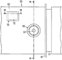
- FIG. 6 is a schematic cross-sectional view showing the configuration of the extension beam drop-out prevention detecting device 70 in the section VII-VII in FIG. 5.
- FIG. 5 is a schematic cross-sectional view showing a state in which a detector 73 detects a striker 75 (detected part) in the detection device 70 for preventing the extension beam from coming out.
- FIG. 8 is a schematic cross-sectional view showing the configuration of the extension beam drop-out prevention detecting device 70 in the section IX-IX in FIG. 7.
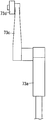
- 3 is a schematic front view showing a configuration of a detector 73.
- FIG. 4 is a schematic side view showing the configuration of a detector 73.
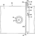
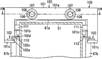
- FIG. 14 is a schematic cross-sectional view showing the configuration of the expansion / contraction beam drop-out prevention detecting device 100 along the XIV-XIV cross section of FIG. 13.
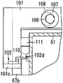
- FIG. 3 is a schematic cross-sectional view showing a partial configuration of a detection device 100 for preventing expansion / contraction beam withdrawal.
- FIG. 3 is a schematic cross-sectional view showing a partial configuration of a detection device 100 for preventing expansion / contraction beam withdrawal. It is a schematic diagram which shows the attachment method of the attachment plate 101 to the telescopic beam 50 in the XVII-XVII cross section of FIG. It is a model side view which shows each partial structure of the expansion-contraction beam 50 and the expansion-contraction beam drop-out prevention detection apparatus 120 in the crawler crane which concerns on 3rd Embodiment.
- FIG. 19 is a schematic cross-sectional view showing the configuration of the expansion / contraction beam drop-out prevention detecting device 120 in the XIX-XIX cross section of FIG. FIG.
- FIG. 20 is a schematic cross-sectional view showing the configuration of the expansion / contraction beam drop-out prevention detection device 120 in the section XX-XX in FIG. 19. It is a model side view which shows the structure of the detection apparatus 120 for a telescopic beam drop-out prevention which concerns on 3rd Embodiment.
- FIG. 3 is a schematic plan view showing the configuration of a telescopic beam dropout prevention detecting device 120.
- FIG. 23 is a schematic cross-sectional view showing a configuration of a telescopic beam drop-out prevention detecting device 120 in a section XXIII-XXIII in FIG.
- the crawler crane 1 includes a crane body 10, a self-propelled counterweight carriage 40, and an extendable beam 50 that connects them.
- the crane body 10 includes a lower traveling body 12, an upper swing body 12, a cab 15, a boom 16, a mast 17, a gantry 18, and a counterweight 19.
- the lower traveling body 12 travels by the crawler 11.
- the upper turning body 14 is installed on the lower traveling body 12 with a turning device 13 interposed, and can turn.
- the cab 15 is provided at the front part of the upper swing body 14.
- the boom 16 is supported at the front of the upper swing body 14 and on the side of the cab 15.
- the boom 16 is supported in a state where the base end thereof can be raised and lowered, in other words, can be rotated around a horizontal axis.
- the mast 17 is supported near the rear end of the base end (boom foot) of the boom 16 at the front portion of the upper swing body 14.
- the mast 17 is supported in a state where the proximal end can be raised and lowered.
- the gantry 18 and the counterweight 19 are provided at the rear part of the upper swing body 14.
- the suspension hook 22 is suspended from the tip of the boom 16 via a hoisting rope 21.
- One end of the hoisting rope 21 is wound around a winding drum 23 provided on the upper swing body 14 through the back side of the boom 16. Then, the hoisting rope 22 is wound or unwound by winding or unwinding the hoisting rope 21 by the winding drum 23.
- One end of a guy line 24 is connected to the tip of the boom 16, and a spreader 25 is provided at the other end of the guy line 24.
- a boom hoisting rope 27 is wound around the spreader 25 and the spreader 26 provided at the tip of the mast 17.
- One end of the boom hoisting rope 27 is wound around a boom hoisting drum 28 provided at the base end of the mast 17 from the spreader 26 through the back side of the mast 17.
- the boom 16 performs a hoisting operation by winding or unwinding the boom hoisting rope 27 by the boom hoisting drum 28.
- the top of the gantry 18 is connected to the tip of the mast 17 via a guy line 31 and a mast hoisting rope 32.
- the mast hoisting rope 32 is wound around a mast hoisting drum 29 provided at the base end of the gantry 18.
- the counterweight carriage 40 is supported from the tip of the mast 17 via the hanger line 33.
- the guy lines 24 and 31 and the hanger line 33 are not limited to a rope such as a wire rope, and may be formed by connecting a plurality of link members.
- the counterweight carriage 40 has a plurality of wheels 41. In FIG. 1 and FIG. 2, only one wheel is illustrated for convenience of illustration.
- the plurality of wheels 41 are rotationally driven by a hydraulic drive motor 42 (see FIG. 12), and are provided so as to be able to turn around a vertical axis. And when the crane main body 10 moves back and forth, the counterweight carriage 40 runs back and forth in accordance with the movement.
- the counterweight carriage 40 floats from the ground when a suspended load of a predetermined mass or more is lifted by the crane body 10, and the mass at this time is determined according to the length of the telescopic beam 50.
- the counterweight carriage 40 When the telescopic beam 50 is expanded and contracted, the counterweight carriage 40 travels with the rotation axis of the wheel 41 (that is, the axle) oriented in a direction perpendicular to the longitudinal direction of the telescopic beam 50. Specifically, when the telescopic beam 50 is to be reduced, the counterweight carriage 40 is caused to travel in a direction relatively approaching the crane body 10. Thereby, as shown in FIG. 1, the telescopic beam 50 is contracted, and the counterweight carriage 40 approaches the crane body 10.
- a mode in which a relative distance between the crane body 10 and the counterweight carriage 40 is set by running the crane body 10 can also be adopted. Even when such a configuration is adopted, the telescopic beam 50 can be expanded and contracted, and the state shown in FIG. 1 and the state shown in FIG. 2 or a state therebetween can be realized.
- the telescopic beam 50 has two cylindrical members 51 and 52.
- the telescopic beam 50 is formed by nesting these two cylindrical members 51 and 52.
- the cylindrical members 51 and 52 are both cylindrical members having a quadrangular cross section.
- the inner cylindrical member 51 is referred to as an “inner beam”
- the outer cylindrical member 52 is referred to as an “outer beam”.
- one end (front end) of the inner beam 51 is coupled to the rear end portion of the upper swing body 14 of the crane body 10 by a coupling pin or the like, and one end portion (rear end portion) of the outer beam 52. ) Is fixed in a state of penetrating the counterweight carriage 40.
- the other end side (rear end side) of the inner beam 51 is inserted into the inner beam 51 from the other end (front end) of the outer beam 52.
- the length of the telescopic beam 50 is determined in inverse proportion to the insertion length.
- one end of the outer beam 52 may be fixed to the end of the counterweight carriage 40 on the crane body 10 side.
- a plurality of pin insertion holes 53, 53,... are provided at predetermined intervals along the longitudinal direction of the left and right side walls of the inner beam 51, respectively.
- pin insertion devices 55 are provided on the left and right side wall portions on the front end side of the outer beam 52. As shown in FIG. 6, the pin insertion device 55 can insert a pin 54 into one pin insertion hole 53 of the plurality of pin insertion holes 53, 53,... In the inner beam 51. Yes. Thereby, the length of the telescopic beam 50 is determined.
- the pin insertion device 55 has a hydraulic cylinder 57.
- a pin 54 is joined to the rod of the hydraulic cylinder 57.
- the pin 54 can reciprocate between the insertion position inserted into the pin insertion hole 53 and the retraction position withdrawn and retracted from the pin insertion hole 53 by driving of the hydraulic cylinder 57.
- the hydraulic cylinder 57 is fixed to the side wall of the outer beam 52 using a bracket or the like.
- the actuator of the pin insertion device 55 is not limited to the hydraulic cylinder 57 but may be a pneumatic cylinder or an electric cylinder, or may be driven linearly by a combination of a motor and a rack and pinion.
- a predetermined gap is provided between the inner beam 51 and the outer beam 52.
- the inner beam 51 and the outer beam 52 can be smoothly expanded and contracted relatively smoothly by a gap provided therebetween.
- each pad is made of a synthetic resin such as a nylon resin having self-lubricating properties.
- a hydraulic cylinder 66 is disposed along the central axis of the inner beam 51 as shown in FIG.
- the telescopic beam 50 is expanded and contracted, if the expansion and contraction of the telescopic beam 50 by the power of the counterweight carriage 40 and the expansion and contraction of the hydraulic cylinder 66 are synchronized, there is no problem in the expansion and contraction operation, and the counterweight carriage 40 is not moved. There is no problem even if the wheels 41 provided on the counterweight carriage 40 are allowed to freely rotate and the telescopic beam 50 is expanded and contracted only by the expansion and contraction of the hydraulic cylinder 66.
- a rectangular frame-shaped end plate 67 is fixed to the front end of the outer beam 52 so as to surround the outer periphery thereof.
- the crawler crane 1 is provided with a detection device 70 for preventing the extension beam from coming out, as shown in FIG.
- the telescopic beam dropout prevention detecting device 70 includes a mounting plate 72, a detector 73, and a fluctuation mechanism 74.
- the mounting plate 72 is attached to a rectangular opening 68 provided on the side wall portion on the front end side of the outer beam 52 through an opening frame 69.
- the detector 73 is attached to a mounting plate 72.
- the detector 73 is installed between the inner beam 51 and the outer beam 52 of the telescopic beam 50 at a position on the near side where the inner beam 51 comes out of the outer beam 52.
- the position on the near side where the inner beam 51 comes out of the outer beam 52 between the inner beam 51 and the outer beam 52 of the telescopic beam 50 is the position on the front end side of the outer beam 52 or the inner beam 51 in this embodiment.
- the variation mechanism 74 is inserted between the mounting plate 72 and the detector 73.
- the changing mechanism 74 changes the position of the detector 73 following the change between the inner beam 51 and the outer beam 52.
- the mounting plate 72 corresponds to “another member” fixed to the outer beam 52 which is the “first cylindrical member”.
- the detector 73 is composed of a limit switch which is a contact type detector. That is, the detector 73 has a detector main body 73a, a swing lever 73c, and a rotating roller 73d.
- the oscillating lever 73c is held by the detector main body 73a so that its proximal end can rotate around the support shaft 73b. Further, the swing lever 73c is held in the neutral position shown in FIG. 10 by a spring (not shown) when no force is applied from the outside.
- Rotating roller 73d is provided at the tip of swing lever 73c.
- the detector 73 causes the inner beam 51 to escape from the outer beam 52. Detect that it is in the near side position.
- the striker 75 is provided on the outer surface of the side wall of the inner beam 51 as a “detected part”.
- the fluctuation mechanism 74 includes a holding member 76, four traveling rollers 78, 78,..., And two compression coil springs 79, 79. 7 and 8, only two of the four traveling rollers 78, 78,... Are shown for convenience of illustration.
- the holding member 76 is a member that holds the detector 73 and has a rectangular flat plate shape that is long in the longitudinal direction (front-rear direction) of the telescopic beam 50.
- the four traveling rollers 78, 78,... are provided on the left and right, respectively, with the front and rear portions of the holding member 76 being rotatably supported via the axles 77.
- the two compression coil springs 79, 79 are provided as “elastic bodies” between the holding member 76 and the mounting plate 72 respectively in the front and rear.
- the detector 73 is disposed at an intermediate position between the front and rear traveling rollers 78, 78 on the holding member 76.
- the detector 73 is in a state where the rotating roller 73d is directed to the inner beam 51.
- the detector 73 is held by the holding member 76 by screwing the detector main body 73 a to the holding member 76.
- Each traveling roller 78 is provided as a “contact member” or “roller”, and is in contact with the inner beam 51 so as to be able to roll. Further, each traveling roller 78 is set to have a predetermined interval between the outer wall surface of the inner beam 51 and the rotating roller 73d of the detector 73.
- the detector 73 is positioned between the two left and right traveling rollers 78 and 78, and the rotating roller 73 d is provided on the outer surface of the side wall of the inner beam 51 between the two left and right traveling rollers 78 and 78. It comes in contact with the striker 75.
- each compression coil spring 79 urges each traveling roller 78 to always contact the outer surface of the side wall of the inner beam 51. As shown in FIG.
- the fluctuation mechanism 74 has fastening bolts 80, 80 corresponding to the compression coil springs 79.79.
- the fastening bolt 80.80 does not move too much in the axial direction or the rotating direction of the telescopic beam. It is used to make it. That is, the threaded portion of the fastening bolt 80 is inserted into a bolt insertion hole (baka hole, not shown) provided in the mounting plate 72, and the tip of the threaded portion is provided on the end surface of the holding member 76. Screwed into a tapped hole (not shown).
- the compression coil spring 79 is installed in a compressed state by being restrained by the inner beam 51 and the mounting plate 72.
- the changing mechanism 74 moves from a predetermined position in the axial direction or the rotating direction of the telescopic beam 50, the position does not change more than necessary due to the presence of the fastening bolt 80.
- the screw portion of the fastening bolt 80 is screwed into a screw hole (not shown) provided in the mounting plate 72.
- a screw hole (not shown) provided in the mounting plate 72.
- the head of the fastening bolt 80 is in contact with the mounting plate 72, and the tip of the threaded portion of the fastening bolt 80 is not in contact with the holding member 76. It is also possible to do.
- the compression coil spring 79 is compressed by being constrained by the inner beam 51 and the mounting plate 72 by installing the fluctuation mechanism 74 at a predetermined position.
- the changing mechanism 74 moves from a predetermined position in the axial direction or the rotating direction of the telescopic beam 50, the presence of the fastening bolt 80 does not change the position more than necessary.
- the clearance between the fastening bolt 80 and the holding member 76 is larger than the clearance between the inner beam 51 and the outer beam 52, and a clearance between a mounting hole 106 and a threaded portion of the bolt 108, which will be described later (see FIGS. 14 to 16). See).
- the counterweight carriage 40 has a hydraulic drive motor 42, a switching valve 92, and a hydraulic pressure source 91.
- the drive motor 42 drives the wheels 41 of the counterweight carriage 40 upon receiving hydraulic pressure.
- the switching valve 92 is provided between the hydraulic pressure source 91 and the drive motor 42, and is a valve for controlling supply of hydraulic pressure to the drive motor 42 and stop thereof.
- the detection signal is Are input to the controller 90.
- the controller 90 issues a command to switch the switching valve 92 to the neutral position.
- the switching valve 92 cuts off the hydraulic pressure supply to the drive motor. Thereby, the drive of the drive motor 42 is stopped and the movement of the counterweight carriage 40 is stopped.
- the controller 90 when the controller 90 receives a detection signal from the detector 73, a command for setting the switching valve 92 to the neutral position is issued, and the drive of the drive motor 42 of the counterweight carriage 40 is stopped.
- the following forms can also be adopted.
- the crane body 10 includes a drive motor that drives the crawler 11 of the lower traveling body 12, a hydraulic source that supplies hydraulic pressure to the drive motor, and a switching valve that is provided between the drive motor and the hydraulic source. Assume form.
- the controller 90 that has received the detection signal from the detector 73 instructs the switching valve of the crane body 10 to switch the switching valve to the neutral state.
- the switching valve that receives the switching command cuts off the hydraulic pressure supply to the drive motor of the crane body 10. Thereby, the drive of the crane main body 10 is stopped.
- the detector 73 causes the inner beam 51 of the telescopic beam 50 to come out of the outer beam 52.
- the crane body 10 can be stopped when it is detected that the position is on the near side.
- the telescopic beam dropout prevention detecting device 70 follows the change in the gap between the inner beam 51 and the outer beam 52 with the detector 73 configured as described above and the position of the detector 73 as described above. And a fluctuation mechanism 74 that fluctuates.
- the position of the detector 73 follows the change. Is varied by the variation mechanism 74.
- the changing mechanism 74 changes the position of the detector 73 in the cross-sectional direction of the inner beam 51 and the outer beam 52 in the telescopic beam 50.
- the rotating roller 73d of the detector 73 and the inner beam 51 opposed thereto are opposed to each other with a predetermined gap. For this reason, it is possible to reliably perform detection by contact between the rotating roller 73d of the detector 73 and the striker 75, and to prevent the rotating roller 73d of the detector 73 from directly hitting the inner beam 51 and being damaged. can do.
- the crawler crane 1 is provided with the detection device 70 for preventing the extension beam from coming out, and the detector 73 of the detection device 70 detects that the inner beam 51 of the extension beam 50 is in a position on the near side where the inner beam 51 comes out from the outer beam 52.
- the controller 90 is configured to stop the counterweight carriage 40 or the crane body 10. For this reason, it is possible to prevent the inner beam 51 of the telescopic beam 50 from coming out or falling off.
- the detector 73 may be a contact type or a non-contact type.
- the detector 73 is a limit switch that is a contact type detector installed on the outer beam 52 of the telescopic beam 50.
- the detector 73 composed of a limit switch is more suitable for outdoor use exposed to dust, wind and rain, temperature changes, etc., like the crawler crane 1, as compared with the case where the detector is a non-contact type. Can improve the reliability.
- the use of the contact type detector 73 is more preferable as the detector 73 is closer to the outside as at the end of the telescopic beam 50, that is, at a position where it is more likely to be affected by dust or the like.
- the detector 73 is installed on the outer beam 52 of the telescopic beam 50, so that the installation of the detector 73 and the wiring work of signal lines connected to the detector 73 are relatively easy. It can be carried out.
- the fluctuation mechanism 74 includes a holding member 76, four traveling rollers 78, 78,..., And two compression coil springs 79, 79.
- the holding member 76 is a member that holds the detector 73 as described above.
- the four traveling rollers 78, 78,... Are members as contact members or rolling elements attached to the holding member 76.
- the two compression coil springs 79 and 79 are members as elastic bodies interposed between the holding member 76 and the mounting plate 72 fixed to the outer beam 52.
- Each traveling roller 78 comes in contact with the inner beam 51 so that the rotating roller 73d of the detector 73 faces the inner beam 51 with a predetermined gap therebetween.
- Each compression coil spring 79 urges each traveling roller 78 to always contact the inner beam 51.
- each traveling roller 78 attached to the holding member 76 receives the urging force of each compression coil spring 79 interposed between the holding member 76 and the attachment plate 72 and always contacts the inner beam 51. It has become a state.
- the rotating roller 73d of the detector 73 held by the holding member 76 is surely opposed to the inner beam 51 by a predetermined gap by each traveling roller 78. For this reason, the reliability of operation
- each traveling roller 78 as a contact member or a rolling element comes into contact with the inner beam 51 so as to be able to roll, wear of each traveling roller 78 due to this contact can be reduced. it can.
- the attachment position of the variation mechanism 74 is installed at a position away from the end plate 67, but it may be installed at a position close to the end plate 67, and the attachment plate 72 may be attached to the end plate 67.
- the opening frame 69 may be attached.
- the telescopic beam 50 can be extended as long as possible. Also, the extension amount of the telescopic beam 50 can be changed by changing the position of the striker 75.
- FIGS. 13 to 17 show a configuration of the detection device 100 for preventing extension / retraction beam withdrawal of the crawler crane according to the present embodiment.
- the configuration of the telescopic beam 50 is substantially the same as that of the first embodiment, and the same members are denoted by the same reference numerals and description thereof is omitted.
- the telescopic beam dropout prevention detecting device 100 includes a mounting plate 101, two detectors 102, 102, a variation mechanism 103, and the like. It has.
- the mounting plate 101 is attached to an end plate 67 provided at the front end of the outer beam 52 of the telescopic beam 50.
- the two detectors 102 and 102 are attached to the attachment plate 101.
- Each detector 102 is positioned between the inner beam 51 and the outer beam 52 of the telescopic beam 50 on the near side where the inner beam 51 comes out of the outer beam 52 (specifically, the position of the end plate 67 on the front end side of the outer beam 52). Is installed.
- the variation mechanism 103 uses the mounting plate 101 as one constituent member.
- the changing mechanism 103 changes the position of each detector 102 following the change in the gap between the inner beam 51 and the outer beam 52.
- the mounting plate 101 constitutes one constituent member of the fluctuation mechanism 103 as a holding member that holds each detector 102.
- the mounting plate 101 has an upper side part 101a, two side parts 101b and 101b, and flange parts 101c and 101c.
- the upper side portion 101 a faces the upper frame portion 67 a of the end plate 67.
- the two side portions 101b and 101b are respectively suspended from the left and right ends of the upper side portion 101a and are opposed to the upper portions of the side frame portions 67b of the end plate 67, respectively.
- the flange portions 101c and 101c are formed by bending the lower end portions of both side portions 101b and 101b at substantially right angles.
- each tapped block 104 has a screw hole 105 on its center line.
- the upper side portion 101 a of the mounting plate 101 is provided with two left and right mounting holes 106, 106 corresponding to the tapped block 104.
- the inner diameter of each mounting hole 106 is set to a so-called fool hole that is larger than the outer diameter of the tapped block 104.
- each tapped block 104 in the center line direction is set to be slightly larger than the thickness dimension of the upper side portion 101a of the mounting plate 101.
- the mounting plate 101 When mounting the mounting plate 101, first, the mounting plate 101 is brought into contact with or close to the end plate 67 with the tapped block 104 inserted into each mounting hole 106. Next, in this state, a washer 107 larger than the attachment hole 106 is brought into contact with the tip of the tapped block 104. Thereafter, the screw portion of the bolt 108 is screwed into the screw hole 105 of the tapped block 104 through the center hole 109 of the washer 107.
- the attachment plate 101 is attached to the end plate 67 in a state of being movable along the end plate 67 which is a plane orthogonal to the axial direction thereof.
- the attachment plate 101 is attached to the outer beam 52 via the end plate 67.
- this movement is limited to a range where the mounting plate 101 does not directly contact the inner beam 51.
- a washer similar to the washer 107 is disposed between the mounting plate 101 and the upper frame portion 67 a of the end plate 67. Further, a through hole is provided in the upper frame portion 67 a of the end plate 67. Next, the threaded portion of the bolt 108 is passed through the central hole 109 of the washer 107, the mounting hole 106 of the mounting plate 101, the central hole of the washer, and the through hole of the upper frame portion 67a of the end plate 67. And you may make it fix the thread part of the volt
- each detector 102 includes a limit switch that is a contact type detector, like the detector 73 in the first embodiment.
- Each detector 102 has a detector main body 102a, a swing lever 102c, and a rotating roller 102d.
- the detector body 102 a is fixed to the upper surface of the flange portion 101 c of the mounting plate 101 with the swing lever 102 c and the rotating roller 102 d facing the outer surface of the side wall portion of the inner beam 51.
- Each detector 102 is in a position on the near side where the inner beam 51 comes out of the outer beam 52 when the rotating roller 102d comes into contact with the striker 110 as a detected portion provided on the outer surface of the side wall portion of the inner beam 51. Detect something.
- the variation mechanism 103 includes pads 111, 111 in addition to the mounting plate 101 as a holding member that holds each detector 102.
- the pads 111 and 111 are provided as two left and right contacts respectively attached to the inner edges of the side portions 101b of the mounting plate 101.
- Each pad 111 is made of a synthetic resin such as a nylon resin having self-lubricating properties.
- Each pad 111 is always in contact with a corresponding side surface portion of the inner beam 51, so that the rotating roller 102 d of the detector 102 corresponding to each pad 111 is separated from the inner beam 51 by a predetermined gap. And come to face each other.
- the detection device 100 for the extension / removal beam prevention also includes the two detectors 102 and 102 configured as described above, and the positions of the detectors 102 and the inner beam 51. And a fluctuation mechanism 103 that fluctuates following the change in the gap between the outer beams 52. For this reason, the same effect as the case of a 1st embodiment can be produced.
- the mounting plate 101 as a holding member that holds the detector 102 is movable along the end plate 67 that is a plane perpendicular to the axial direction of the outer beam 52. It is attached.
- the left and right pads 111, 111 attached to the inner edges of the side portions 101b of the attachment plate 101 are always in contact with the inner beam 51, respectively.
- Each pad 111, 111 is provided as a slider.
- the mounting plate 101 is made of a relatively thin and light member, there is almost no resistance force due to contact with the inner beam 51, and the frictional force that causes wear of the pad 111 is also very small. . For this reason, the wear of the pad 111 hardly occurs, and the gap between the side portion 101b of the mounting plate 101 and the inner beam 51 can be kept constant over a long period of time.
- the pad 111 since the pad 111 needs to be in constant contact with the inner beam 51, the pad 111 is pressed against the inner beam 51 from the side portion 101 b of the mounting plate 101 with a bolt or a spring. It is preferable to provide a mechanism or a mechanism for adjusting the pressing state.
- the gap between the mounting hole 106 of the mounting plate 101 and the threaded portion of the bolt 108 is the same as or larger than the gap between the inner beam 51 and the outer beam 52. This is because the mounting plate 101 moves when the mounting plate 101 is in contact with the pad 111 in accordance with the change in the gap between the inner beam 51 and the outer beam 52. Therefore, the mounting hole 106 of the mounting plate 101 and the threaded portion of the bolt 108 are moved. If the clearance between the inner beam 51 and the outer beam 52 varies, the mounting hole 106 and the threaded portion of the bolt 108 come into contact with each other first, thereby making it impossible to follow.
- the gap between the screw portion of the bolt 106 and the bolt 108 is made larger by the amount of wear.
- FIGS. 18 to 23 show a configuration of the detecting device 120 for preventing the extension beam from coming out of the crawler crane according to the present embodiment.
- the configuration of the telescopic beam 50 is substantially the same as in the first embodiment, and the same members are denoted by the same reference numerals, and the description thereof will be omitted.
- the telescopic beam dropout prevention detecting device 120 is attached to an end plate 67 provided at the front end of the outer beam 52 of the telescopic beam 50.
- the telescopic beam drop-out prevention detecting device 120 is attached to the upper portion of one side frame portion 67b of the end plate 67, but may be attached to another portion of the end plate 67. .
- the detection device 120 for preventing expansion / contraction beam dropout includes a case body 121, a detector 122, and a fluctuation mechanism 123.
- the case body 121 is attached to the front side of the end plate 67.
- the detector 122 is partially housed inside the case body 121. As shown in FIGS. 18 and 20, the detector 122 is installed between the inner beam 51 and the outer beam 52 of the telescopic beam 50 at a position on the near side where the inner beam 51 comes out of the outer beam 52. More specifically, the detector 122 is installed at the position of the end plate 67 on the front end side of the outer beam 52.
- the variation mechanism 123 is provided so as to be interposed between the case main body 121 and the detector 122.
- the changing mechanism 123 changes the position of the detector 122 following the change in the gap between the inner beam 51 and the outer beam 52.
- the case body 121 includes a main side plate 124, a sub side plate 125, and an intermediate plate 126 disposed between the both side plates 124 and 125.
- the intermediate plate 126 is fixed to the main side plate 124 and the sub side plate 125 by fillet welding or the like.
- the main side plate 124 is formed in a substantially isosceles trapezoidal shape in which the vertical dimension gradually increases toward the end plate 67 side.
- the main side plate 124 is provided with a pair of insertion holes 127 and 127 at two positions on the upper and lower sides of the end portion on the end plate 67 side.
- the case main body 121 is fixed to the end plate 67 by fixing tools 128 (see FIGS. 18 and 19) such as bolts and screws inserted into the respective insertion holes 127.
- the sub-side plate 125 is formed in a rectangular shape.
- the vertical dimension (length in the short direction) of the auxiliary side plate 125 is substantially the same as the vertical dimension of the main side plate 124 on the side opposite to the end plate.
- the length of the sub-side plate 125 in the longitudinal direction is substantially the same as that of the main side plate 124.
- the intermediate plate 126 has an upper wall portion 126a, a lower wall portion 126b, and a back wall portion 126c.
- the rear wall 126c extends in the vertical direction along the opposite end plate side ends of the main side plate 124 and the sub side plate 125.
- the upper wall portion 126a extends in the horizontal direction from the upper end of the back wall portion 126c along the upper edge of the sub-side plate 125 to the middle position in the longitudinal direction of the sub-side plate 125.
- the lower wall portion 126b extends in the horizontal direction from the lower end of the back wall portion 126c along the lower edge of the sub-side plate 125 to the middle position in the longitudinal direction of the sub-side plate 125.
- the horizontal length of the lower wall portion 126b is longer than that of the upper wall portion 126a.
- the case body 121 has the accommodating part 129 open
- the detector 122 includes a limit switch that is a contact type detector, like the detector 73 in the first embodiment.
- the detector 122 includes a detector main body 122a, a swing lever 122c, and a rotating roller 122d.
- the detector main body 122a of the detector 122 is fixed to a holding member 131 (to be described later) with the swing lever 122c and the rotating roller 122d facing the outer surface of the side wall of the inner beam 51.
- the rotating roller 122d comes into contact with a striker as a detected portion provided on the outer surface of the side wall of the inner beam 51, and the swing lever 122c tilts as indicated by a virtual line in FIG. It is detected that the beam 51 is in a position on the near side where it comes out of the outer beam 52.
- the fluctuation mechanism 123 has a holding member 131 that holds the detector 122.
- the holding member 131 is a plate-like member that is formed in a substantially U shape as a whole, and is a connecting portion that connects a pair of upper and lower leg portions 131a and 131a and base ends of the pair of upper and lower leg portions 131a and 131a. 131b.
- the base end side of the connecting portion 131b and each leg portion 131a of the holding member 131 is fitted in the housing portion 129 of the case body 121 so as to be slidable in the horizontal direction.
- the base end side of the connecting portion 131b and each leg portion 131a of the holding member 131 is slidable in a direction perpendicular to the side wall portion of the inner beam 51 with respect to the storage portion 129 of the case body 121. It is mated.
- the upper leg portion 131a of the holding member 131 is slidably in contact with the lower surface of the upper wall portion 126a of the intermediate plate 126 of the case body 121. Further, the lower leg portion 131 a of the holding member 131 is slidably in contact with the upper surface of the lower wall portion 126 b of the intermediate plate 126 of the case body 121.
- the detector main body 122a of the detector 122 is fixed to the inner surface side (upper surface side) of the lower leg 131a of the holding member 131 by fastening bolts or the like.
- the swing lever 122c and the rotating roller 122d are in a state facing the outer surface of the side wall portion of the inner beam 51 between the pair of upper and lower leg portions 131a and 131a.
- the variation mechanism 123 is disposed outside the holding member 131.
- the fluctuation mechanism 123 has two upper and lower traveling rollers 133 and 133 and one compression coil spring 134.
- the pair of upper and lower traveling rollers 133 and 133 are rotatably supported at the tip end portions of the leg portions 131 a of the holding member 131 via the support shafts 132.
- Each traveling roller 133 is a contact member or a rotator, and is in contact with the inner beam 51 so that the rotation roller 73d of the detector 73 faces the inner beam 51 with a predetermined gap therebetween.
- the compression coil spring 134 is an elastic body and is interposed between the connecting portion 131 b of the holding member 131 and the back wall portion 126 c of the intermediate plate 126 of the case body 121.
- the compression coil spring 134 urges each traveling roller 133 to always contact the inner beam 51 in a compressed state described later.
- case body 121 corresponds to “another member” fixed to the outer beam 52 which is one cylindrical member.
- the variation mechanism 123 causes the holding member 131 to intervene when the compression coil spring 134 is interposed between the connecting portion 131 b of the holding member 131 and the inner wall 126 c of the intermediate plate 126 of the case body 121.
- the screw rod 135 and the nut 136 are used for restricting the case body 121 from coming out of the housing portion 129 of the case body 121.
- the screw rod 135 is inserted into an insertion hole (fool hole, not shown) provided in the inner wall 126c of the intermediate plate 126 of the case body 121.
- One end of the screw rod 135 is fixed by welding while being screwed into a screw hole (not shown) provided in the connecting portion 131b of the holding member 131.
- the nut 136 screwed into the other end portion of the screw rod 135 is in the back wall portion 126 c of the intermediate plate 126 of the case body 121 in the use state of the detection device 120 for preventing the extension beam from coming out. It will be in a state away from. In this state, the compression coil spring 134 is compressed between the connecting portion 131b of the holding member 131 and the inner wall 126c of the intermediate plate 126 of the case body 121, and generates an urging force (reaction force) in this compressed state. It is like that.
- a signal line 141 is connected to the detector 122. As shown in FIG. 23, the signal line 141 is led out of the case body 121 through a lead-out port 142 provided in the main side plate 124 of the case body 121.
- the detection device 120 for preventing the extension beam from coming out is a detection device installed at a position between the inner beam 51 and the outer beam 52 of the extension beam 50 at a position on the near side where the inner beam 51 comes out of the outer beam 52. Since the detector 122 and the changing mechanism 123 that changes the position of the detector 122 following the change in the gap between the inner beam 51 and the outer beam 52 are provided, the same action as in the first embodiment is provided. There is an effect.
- the fluctuation mechanism 123 of this embodiment includes a holding member 131 that holds the detector 122, two traveling rollers 133 and 133 as contact members or rolling elements attached to the holding member 131, and a holding member 131. And a compression coil spring 134 as an elastic body interposed between the outer casing 52 and a case body 121 fixed to the outer beam 52 (specifically, an end plate 67 provided at the front end of the outer beam 52).
- Each traveling roller 133 comes into contact with the inner beam 51 so that the rotating roller 122d of the detector 122 faces the inner beam 51 with a predetermined gap therebetween, and the compression coil spring 134 is connected to each traveling roller. 133 is urged to always contact the inner beam 51.
- each traveling roller 133 attached to the holding member 131 receives the urging force of the compression coil spring 134 interposed between the holding member 131 and the case body 121 and receives the inner beam 51. Always in contact. Then, the rotating roller 122d of the detector 122 held by the holding member 131 is reliably opposed to the inner beam 51 with a predetermined gap by each traveling roller 133. For this reason, the reliability of operation
- the detection device 120 for preventing the extension beam from coming out can be easily attached to the end plate 67 provided at the front end of the outer beam 52. It can be extended as long as possible.
- this indication is not limited to the said 1st thru
- a contact-type detector 73 is attached to the front end side of the outer beam 52 of the telescopic beam 50, while a striker 75 as a detected portion is provided on the rear end side of the inner beam 51 of the telescopic beam 50. It was.
- a contact-type detector may be attached to the rear end side of the inner beam 51, while a detected portion may be provided on the front end side of the outer beam 52.
- the traveling roller 78 is used as an example of the contact member in the variation mechanism 74, but the present disclosure is not limited thereto.
- a slide member may be used in place of the traveling roller 78 or in combination with the traveling roller 78.
- the detector 73 is slidably or slidably contacted with the inner beam 51 so as to face the inner beam 51 at a predetermined interval, and the contact adversely affects the expansion and contraction of the telescopic beam 50. You don't have to.
- the fluctuation mechanism 74 includes four traveling rollers 78, 78,... On the front and rear, left and right of the holding member 76, and two compression coil springs 79 and 79 on the front and rear of the holding member 76.
- the detector 73 is held at an intermediate position between the front and rear traveling rollers 78 and 78 of the holding member 76. This is to prevent the detector 73 from contacting and reacting with the inner beam 51 by tilting the holding member 76 or the like.
- the present disclosure is not limited to this.
- the traveling roller and the compression coil spring can be made one each by preventing the holding member from being tilted.
- the compression coil spring 79 is employed as an example of the elastic body, but the present disclosure is not limited thereto.
- a spring other than the compression coil spring for example, a leaf spring, a torsion bar, a disc spring, a spiral spring, a bamboo spring, a ring spring, etc.
- rubber, or the like may be used as the elastic body.
- the mounting plate 101 when the mounting plate 101 is movably mounted along the end plate 67 provided at the front end of the outer beam 52 of the telescopic beam 50, the mounting plate 101 is mounted for each of the two left and right mounting holes 106.
- a washer 107 larger than the hole 106 was used, the present disclosure is not limited to this configuration.
- a plate that covers the two left and right mounting holes 106, 106 of the mounting plate 101 may be used.
- the elastic body is not disposed between the mounting hole 106 of the mounting plate 101 and the tapped block 104.
- the present disclosure is not limited to this configuration.
- the tapped block 104 fixed to the end plate 67 is inserted into the mounting hole 106 of the mounting plate 101, and the threaded portion of the bolt 108 is inserted into the screw hole 105 of the tapped block 104 through the center hole 109 of the washer 107.
- an elastic body may be disposed between the mounting hole 106 of the mounting plate 101 and the tapped block 104.
- the mounting plate 101 can easily return to the neutral position, and high workability during assembly can be ensured. Become superior. That is, by making the attachment plate 101 easily return to the neutral position by the arrangement of the elastic body, it is possible to prevent the attachment plate 101 from easily moving too much during assembly. Further, the arrangement of the elastic body can prevent the bolt 108 and the mounting plate 101 from colliding violently and being damaged due to the abrupt movement of the mounting plate 101.
- a viscoelastic body for example, ring-shaped rubber or resin
- the above-described effects are obtained. Can be obtained more reliably.
- the detectors 102 are provided at two locations (each flange portion 101c) of the mounting plate 101, but the present disclosure is not limited to this configuration. As a modification, for example, the detector 102 may be provided only at one position of the mounting plate 101.
- the mounting plate 101 is formed in a shape surrounding the upper half portion of the inner beam 51, and pads 111 as contacts are respectively provided on the inner edges of the side portions 101b of the mounting plate 101. Attached.
- the present disclosure is not limited to this configuration.
- the mounting plate is formed in a rectangular frame shape surrounding the entire circumference of the inner beam 51, and each frame portion (upper frame portion, lower frame portion, and left and right side frame portions) of the mounting plate is formed.
- a configuration in which contacts are attached to the inner edges can be employed. When this configuration is adopted, not only the mounting plate moves following the inner beam 51 when moving in the left-right direction, but also when the inner beam 51 moves up and down, the mounting plate follows it. Will move.
- the telescopic beam 50 is formed by nesting two cylindrical members (the inner beam 51 and the outer beam 52). Is not limited to this configuration.
- the present invention can be applied to a case where the telescopic beam is formed by nesting three or more cylindrical members. That is, in this case, one cylindrical member may come out of the other cylindrical member between two cylindrical members adjacent to each other among three or more cylindrical members.
- a detector installed at a position and a changing mechanism that changes the position of the detector following the change in the gap between the two cylindrical members can be provided.
- the position on the near side where one cylindrical member comes out of the other cylindrical member is the position on the rear end side of the adjacent cylindrical member that is connected to or close to the crane body. The position, or the position of the front end side of the cylindrical member connected to or close to the counterweight carriage.
- the tubular member having a rectangular cross section is adopted as the tubular member, but the present disclosure is not limited to this configuration.
- a cylindrical member having a cross-sectional shape such as a polygonal shape, a round shape, an oval shape, or an oval shape may be employed.
- the holding member 131 that holds the detector 122 is configured by one member, but the present disclosure is not limited to this configuration. As a modification, for example, it can be configured by a plurality of members.
- the case body 121 as shown in FIGS. 18 to 23 is adopted as the “other member” fixed to one cylindrical member, but the present disclosure has this configuration.
- the intermediate plate may be composed of two or more members, or the case body may be formed in a cylindrical shape.
- another member can be omitted.
- an elastic body such as a compression coil spring is interposed between the holding member and one cylindrical member, and the elastic member is attached to the holding member by the urging force of the elastic body. You may comprise so that the made contact member may always be in contact with the other cylindrical member.
- the crawler crane is adopted as an example of the “mobile crane”, but the present disclosure is not limited to this.
- a truck crane, a wheel crane, a railway crane, a floating crane on the water, or the like can be adopted.
- the same effect as described above can be obtained by adopting the same detecting device for preventing the extension beam from coming out.
- each aspect of the present disclosure is summarized as follows.
- a crane body and a self-propelled counterweight carriage are connected by an extension beam, and the extension beam has a plurality of cylindrical shapes.
- a telescopic beam of a mobile crane in which members are arranged in a nested manner is set as a detection target.
- the detection device for preventing the extension beam from coming out of the mobile crane according to this aspect includes a detector and a fluctuation mechanism.
- the detector In the cross-sectional direction of the telescopic beam, the detector is between the first and second cylindrical members adjacent to each other inside and outside, and in the telescopic direction of the telescopic beam, the first cylindrical member is At least a portion is installed at a position on the near side that comes out of the second tubular member.
- the variation mechanism is configured such that the position of the detector with respect to the first and second cylindrical members in the cross-sectional direction of the telescopic beam is a gap between the first and second cylindrical members in the cross-sectional direction of the telescopic beam. Change to follow the change of.
- the position of the detector follows the change and the mechanism changes.
- the detector and the cylindrical member on the side of the detected part facing the detector face each other with a predetermined gap therebetween.
- the changing mechanism changes the position of the detector in the cross-sectional direction of the telescopic beam.
- the detection device for preventing the extension beam from falling out is configured such that the detector is installed in the first cylindrical member, and the second cylindrical shape is provided. When the detected portion provided on the member is detected, it is detected that the first cylindrical member is in a position on the near side where the first cylindrical member comes out of the second cylindrical member.
- the first cylindrical member is a cylindrical member arranged on the outside with respect to the second cylindrical member
- the second cylindrical member is In the case of the cylindrical member arranged on the inner side with respect to the first cylindrical member, it is possible to relatively easily perform installation of a detector, wiring of a signal line connected to the detector, and the like. .
- the detection device for preventing extension beam escape has the variation mechanism including a holding member, a contact member, and an elastic body.
- the holding member holds the detector.
- the contact member is attached to the holding member, and can roll or slide so that the detector faces the second cylindrical member with a predetermined gap in the cross-sectional direction of the telescopic beam. To touch.
- the elastic body is interposed between the holding member and the first cylindrical member or another member fixed to the cylindrical member, and always brings the contact member into contact with the second cylindrical member. Energize as follows.
- the contact member attached to the holding member is between the holding member and the first cylindrical member or another member fixed to the first cylindrical member.
- the detector that is constantly in contact with the second cylindrical member by receiving the urging force (elastic reaction force) of the elastic body inserted in and attached to the second cylindrical member is held by the contact member. It comes to face reliably with a predetermined gap. Therefore, when this mode is adopted, reliable detection as described above and prevention of breakage of components can be more reliably achieved.
- the detection device for preventing extension beam escape is configured such that the contact member is a rotator that comes into contact with the second cylindrical member so as to allow rolling.
- the detection device for preventing extension beam escape has the variation mechanism including a holding member and a plurality of contacts.
- the holding member is attached to the first cylindrical member so as to be movable along a plane orthogonal to the axial direction thereof, and holds the detector.
- the plurality of contacts are respectively attached to the holding member and are always in contact with the second cylindrical member so that the detector faces the second cylindrical member with a predetermined gap therebetween. It is a member for making.
- the holding member for holding the detector is attached to the first cylindrical member so as to be movable along a plane orthogonal to the axial direction thereof.
- Each of the plurality of contacts attached to the detector is always in contact with the second cylindrical member, so that the detector reliably faces the second cylindrical member with a predetermined gap therebetween. You can do that.
- the detection device for preventing the extension beam from falling out is configured such that the detector is a contact-type detector.
- the contact-type detector is suitable for outdoor use exposed to dust, wind and rain, and in this aspect in which the contact-type detector is employed as the detector, higher reliability can be obtained.
- a mobile crane includes a crane main body, a counterweight carriage, a telescopic beam, a detector, a fluctuation mechanism, and a controller.
- the telescopic beam connects the crane body and the counterweight carriage, and a plurality of cylindrical members are arranged in a nested manner.
- the detector In the cross-sectional direction of the telescopic beam, the detector is between the first and second cylindrical members adjacent to each other inside and outside, and in the telescopic direction of the telescopic beam, the first cylindrical member is It is detected that at least a part is installed at a position on the near side where the second cylindrical member comes out of the second cylindrical member, and that the first cylindrical member is located on a near side where the second cylindrical member comes out from the second cylindrical member.
- the variation mechanism is configured such that the position of the detector with respect to the first and second cylindrical members in the cross-sectional direction of the telescopic beam is a gap between the first and second cylindrical members in the cross-sectional direction of the telescopic beam. Change to follow the change of.
- the controller stops at least one of the counterweight carriage and the crane body when the detector detects that the first cylindrical member is in a position on the near side where the first cylindrical member comes out of the second cylindrical member.
- the changing mechanism changes the position of the detector in the cross-sectional direction of the telescopic beam.
- the predetermined clearance gap between the detector and the cylindrical member by the side of the to-be-detected part facing this is maintained.
- the controller is a self-propelled counterweight carriage or crane. Since the main body is stopped, it is possible to prevent the telescopic beam from coming out or falling off.
Landscapes
- Engineering & Computer Science (AREA)
- Mechanical Engineering (AREA)
- Jib Cranes (AREA)
Abstract
伸縮ビームの抜け出し防止用検知装置は、複数の筒状部材が入れ子状に配置されてなる伸縮ビームを検知対象とする。伸縮ビームの抜け出し防止用検知装置は、検知器と、変動機構と、を備える。検知器は、伸縮ビームの断面方向において、互いに内外に隣接する第1及び第2の筒状部材間であって、かつ、伸縮ビームの伸縮方向において、第1の筒状部材が第2の筒状部材から抜け出す手前側の位置に少なくとも一部が設置されている。変動機構は、伸縮ビームの断面方向における第1及び第2の筒状部材に対する検知器の位置を、伸縮ビームの断面方向における第1及び第2の筒状部材間の隙間の変化に追従して変動させる。
Description
本開示は、移動式クレーンの伸縮ビーム抜け出し防止用検知装置及び移動式クレーンに関する。
移動式クレーンにおいては、その吊り上げ能力を高めるために、例えば特許文献1に記載されているように、クレーン本体の後方にカウンターウェイト台車を配置し、このカウンターウェイト台車とクレーン本体とを伸縮ビームにより連結することがある。伸縮ビームは、通常、2つの筒状部材(インナービームとアウタービーム)を入れ子状に配置してなるため、例えばカウンターウェイト台車が自走式のもので、台車の自走つまり移動により伸縮ビームを伸長させるとき、伸縮ビームの一方の筒状部材が他方の筒状部材から抜け出さないように、抜け止め機構を設けるか、あるいは伸縮ビームの一方の筒状部材が他方の筒状部材から抜け出す手前側の位置でカウンターウェイト台車の移動を停止させることが必要となる。
抜け止め機構は、カウンターウェイト台車の質量と移動速度による慣性力に抗してカウンターウェイト台車の移動を停止させるために、大きくかつ頑丈なものにする必要があり、その分質量が増加し、コストが高くなるという欠点がある。
一方、伸縮ビームの一方の筒状部材が他方の筒状部材から抜け出す手前側の位置でカウンターウェイト台車を停止させるように制御する構成の場合、構成が大掛かりになることはないので、質量の軽減化及びコストの低廉化を図ることができるという利点がある。具体的な構成としては、メンテナンス性や取り付け容易性を考慮して、伸縮ビームのアウタービームにリミットスイッチなどの接触式検知器を取り付ける一方、伸縮ビームのインナービームにストライカーなどの被検知部を取り付ける。そして、カウンターウェイト台車の移動により伸縮ビームを伸長させるとき、前記接触式検知器が前記被検知部に接触することにより伸縮ビームの筒状部材間で一方の筒状部材が他方の筒状部材から抜け出す手前側の位置にあることを検知し、カウンターウェイト台車の移動を停止させることが行われている。
ところで、前記伸縮ビームのインナービームとアウタービームの間には、稼動を円滑にするための隙間があり、調整シムやパッドなどで隙間を確保している。
しかし、インナービームとアウタービームとの間の隙間は、伸縮ビームの製造時の公差や使用経年によるパッドなどの摩耗などで一定ではない場合が生じ得る。このため、単に検知器をアウタービームに固定すると、隙間の変化により検知器がインナービームに対し近づいたり遠ざかったりして、インナービームに取り付けた被検知部に設計通り接触しない可能性がある。また、検知器が被検知部ではなく、インナービームに直接当たってしまう可能性もある。
なお、上記のような問題は、移動式クレーンの伸縮ビームに限らず、種々の伸縮ビームにおいても生じ得る問題である。
本開示はかかる点に鑑みてなされたものであり、伸縮ビームの筒状部材間の隙間が製造時の公差や使用経年によるパッドなどの摩耗などで変化した場合にあっても、伸縮ビームの筒状部材間で且つ一方の筒状部材が他方の筒状部材から抜け出す手前側の位置にあることを確実に検知することができ、また検知器が検知対象である伸縮ビームの筒状部材に接触あるいは衝突することを抑制し、該検知器の破損を防止できる移動式クレーンの伸縮ビーム抜け出し防止用検知装置、及び、検知器の破損を防止できるとともに、伸縮ビームの抜け出しないし抜け落ちを防止できる移動式クレーンを提供することを目的とする。
本開示の一態様に係る移動式クレーンの伸縮ビーム抜け出し防止用検知装置は、クレーン本体と自走式のカウンターウェイト台車とが伸縮ビームにより連結され、この伸縮ビームが、複数の筒状部材が入れ子状に配置されてなる移動式クレーンの伸縮ビームを検知対象とする。本態様に係る移動式クレーンの伸縮ビーム抜け出し防止用検知装置は、検知器と、変動機構と、を備える。
前記検知器は、前記伸縮ビームの断面方向において、互いに内外に隣接する第1及び第2の筒状部材間であって、かつ、前記伸縮ビームの伸縮方向において、前記第1の筒状部材が前記第2の筒状部材から抜け出す手前側の位置に少なくとも一部が設置されている。
前記変動機構は、前記伸縮ビームの断面方向における前記第1及び前記第2の筒状部材に対する検知器の位置を、前記伸縮ビームの断面方向における前記第1及び第2の筒状部材間の隙間の変化に追従して変動させる。
以下では、本開示の第1の実施形態について、図面を参酌しながら説明する。なお、以下で説明の形態は、本開示の一態様であって、本開示は、その本質的な構成を除き何ら以下の形態に限定を受けるものではない。
[第1の実施形態]
1.クローラクレーン1の全体構成
本開示の第1の実施形態に係るクローラクレーン1の全体構成について、図1及び図2を用い説明する。本実施形態に係るクローラクレーン1は、移動式クレーンの一例である。
1.クローラクレーン1の全体構成
本開示の第1の実施形態に係るクローラクレーン1の全体構成について、図1及び図2を用い説明する。本実施形態に係るクローラクレーン1は、移動式クレーンの一例である。
図1及び図2に示すように、クローラクレーン1は、クレーン本体10と、自走式のカウンターウェイト台車40と、これらを連結する伸縮ビーム50とを備えている。
クレーン本体10は、下部走行体12と、上部旋回体12と、キャブ15と、ブーム16と、マスト17と、ガントリ18と、カウンターウェイト19と、を有している。
下部走行体12は、クローラ11により走行する。
上部旋回体14は、下部走行体12上に旋回装置13を介在して設置され、旋回可能となっている。
キャブ15は、上部旋回体14の前部に設けられている。
ブーム16は、上部旋回体14の前部で、かつ、キャブ15の側方に支持されている。ブーム16は、その基端が起伏可能な状態で支持されており、換言すると、水平軸回りに回動可能となっている。
マスト17は、上部旋回体14の前部におけるブーム16の基端(ブームフット)の後方近傍に支持されている。マスト17は、基端が起伏可能な状態で支持されている。
ガントリ18及びカウンターウェイト19は、上部旋回体14の後部に設けられている。
図1及び図2に示すように、吊フック22は、ブーム16の先端から巻上ロープ21を介して吊り下げられている。
巻上ロープ21の一端部は、ブーム16の背面側を通して、上部旋回体14に設けた巻き取りドラム23に巻き取られている。そして、巻き取りドラム23により巻上ロープ21を巻き取り又は繰り出すことにより、吊フック22を巻き上げ又は巻き下げるようになっている。
ブーム16の先端部にはガイライン24の一端が連結され、ガイライン24の他端にはスプレッダ25が設けられている。
スプレッダ25と、マスト17の先端に設けられたスプレッダ26と、の間には、ブーム起伏ロープ27が巻き掛けられている。ブーム起伏ロープ27の一端部は、スプレッダ26からマスト17の背面側を通して、マスト17の基端部に設けたブーム起伏ドラム28に巻き取られている。
ブーム16は、ブーム起伏ドラム28によりブーム起伏ロープ27を巻き取り又は繰り出すことにより起伏動作をするようになっている。
ガントリ18の頂部は、マスト17の先端部に対して、ガイライン31及びマスト起伏ロープ32を介して連結されている。マスト起伏ロープ32は、ガントリ18の基端部に設けたマスト起伏ドラム29に巻き取られている。
図1及び図2に示すように、カウンターウェイト台車40は、マスト17の先端部からハンガーライン33を介して支持されている。なお、ガイライン24,31及びハンガーライン33は、いずれもワイヤロープなどのロープに限らず、複数のリンク部材を連結してなるものでもよい。
カウンターウェイト台車40は、複数の車輪41を有している。なお、図1及び図2では、図示の都合上、1つの車輪のみを図示している。
複数の車輪41は、油圧式の駆動モータ42(図12を参照。)により回転駆動されるようになっているとともに、垂直軸回りに旋回可能に設けられている。そして、カウンターウェイト台車40は、クレーン本体10が前後に動くとき、その動きに合わせて前後に走行する。
また、カウンターウェイト台車40は、クレーン本体10の上部旋回体14が旋回するとき、車輪41が地面を走行して旋回する。
また、カウンターウェイト台車40は、所定質量以上の吊り荷をクレーン本体10で吊り上げると地面から浮上するが、このときの質量は、伸縮ビーム50の長さに応じて決定される。
伸縮ビーム50を伸縮させるときには、カウンターウェイト台車40は、車輪41の回転軸(つまり車軸)を伸縮ビーム50の長手方向と直交する方向に向けた状態にされ、走行する。具体的には、伸縮ビーム50を縮小しようとするときには、カウンターウェイト台車40を、クレーン本体10に対し相対的に近づく方向に走行させる。これにより、図1に示すように、伸縮ビーム50が縮小し、クレーン本体10に対してカウンターウェイト台車40が接近した状態となる。
一方、伸縮ビーム50を伸長しようとするときには、カウンターウェイト台車40を、クレーン本体10から相対的に遠ざかる方向に走行させる。これにより、図2に示すように、伸縮ビーム50が伸長し、クレーン本体10に対してカウンターウェイト台車40が遠ざかった状態となる。
なお、クレーン本体10の走行により、クレーン本体10とカウンターウェイト台車40との相対的な距離を設定するという形態も採用可能である。このような形態を採用することとしても、伸縮ビーム50の伸縮が可能となり、図1に示す状態と図2に示す状態、あるいはその間の状態を実現することができる。
2.伸縮ビーム50の構成
伸縮ビーム50の構成について、図3ないし図6を用い説明する。
伸縮ビーム50の構成について、図3ないし図6を用い説明する。
図3ないし図6に示すように、伸縮ビーム50は、2つの筒状部材51,52を有する。伸縮ビーム50は、これら2つの筒状部材51,52を入れ子状に配置してなる。
各筒状部材51,52は、共に四角形断面の筒状の部材である。以下では、内側の筒状部材51を“インナービーム”と記載し、外側の筒状部材52を“アウタービーム”と記載する。
図2で示したように、インナービーム51の一端(前端)は、クレーン本体10の上部旋回体14の後端部に結合ピンなどにより結合されており、アウタービーム52の一端部(後端部)は、カウンターウェイト台車40を貫通した状態で固定されている。
図3及び図4に示すように、インナービーム51の他端側(後端側)は、アウタービーム52の他端(前端)からその内部に挿入されており、アウタービーム52に対するインナービーム51の挿入長さに反比例して伸縮ビーム50の長さが定まる。なお、アウタービーム52の一端部は、カウンターウェイト台車40のクレーン本体10側端部に固定してもよいのは勿論である。
図4及び図6に示すように、インナービーム51の左右側壁部にはそれぞれその長手方向に沿って所定間隔毎に複数のピン挿入孔53,53,・・・が設けられている。
一方、図5及び図6に示すように、アウタービーム52の前端側の左右側壁部には、ピン挿入装置55が設けられている。図6に示すように、ピン挿入装置55は、インナービーム51における複数のピン挿入孔53,53,・・・のうちの1つのピン挿入孔53に対し、ピン54を挿入できるようになっている。これにより、伸縮ビーム50の長さが定められる。
また、図5及び図6に示すように、ピン挿入装置55は、油圧シリンダ57を有している。油圧シリンダ57のロッドにはピン54が接合されている。ピン54は、油圧シリンダ57の駆動により、ピン挿入孔53に挿入した挿入位置と、ピン挿入孔53から引き出して退避した退避位置との間を往復動できるようになっている。
図5及び図6では図示を省略しているが、油圧シリンダ57は、アウタービーム52の側壁部にブラケットなどを用いて固定されている。なお、ピン挿入装置55のアクチュエータとしては、油圧シリンダ57に限らず、空気圧シリンダや電動シリンダを用いたり、モータとラック・ピニオンとの組み合わせで直線上に駆動させたりするものでもよい。
図6に示すように、インナービーム51とアウタービーム52の間には、所定の隙間が設けられている。インナービーム51とアウタービーム52とは、その間に設けられた隙間により円滑に相対的な伸縮動作が可能となっている。
また、図示を省略しているが、アウタービーム52の内面には、インナービーム51との隙間を確保するために複数のパッドが適宜固定されている。各パッドは、自己潤滑性を有するナイロン樹脂などの合成樹脂からなる。
なお、図6に示すようにインナービーム51の中心軸に沿って油圧シリンダ66が配置されている。ここで、伸縮ビーム50を伸縮させる場合、カウンターウェイト台車40の動力による伸縮ビーム50の伸縮と油圧シリンダ66の伸縮が同期していれば伸縮動作に問題はないし、カウンターウェイト台車40を動かさず、カウンターウェイト台車40に備えられた車輪41の回転を自由にしておき、油圧シリンダ66の伸縮のみで伸縮ビーム50を伸縮させても問題はない。
しかし、カウンターウェイト台車40の動力と油圧シリンダ66の動力とが干渉してしまうと伸縮ができなくなることや、意図しない伸縮動作をするおそれがある。このため、油圧シリンダ66を伸縮ビーム50に対し連結しないで動力が伝達されない状態になっている。この場合、カウンターウェイト台車40又はクレーン本体10の動力によって伸縮ビーム50が伸縮する。
また、図3ないし図6に示すように、アウタービーム52の前端にその外周を囲繞するように、矩形枠状のエンドプレート67が固定されている。
ここで、図4に示すように、伸縮ビーム50が最伸長状態でピン挿入装置55によりピン54がピン挿入孔に挿入される位置よりも伸縮ビーム50が伸長したときには、伸縮ビーム50のインナービーム51がアウタービーム52内から抜け出ることになる。これを防止するために、クローラクレーン1は、図5に示すように、伸縮ビーム抜け出し防止用検知装置70を備えている。
3.伸縮ビーム抜け出し防止用検知装置70の構成
伸縮ビーム抜け出し防止用検知装置70の構成について、図7ないし図9を用い説明する。
伸縮ビーム抜け出し防止用検知装置70の構成について、図7ないし図9を用い説明する。
図7ないし図9に示すように、伸縮ビーム抜け出し防止用検知装置70は、取付プレート72と、検知器73と、変動機構74と、を備えている。
前記取付プレート72は、アウタービーム52の前端側の側壁部に設けた矩形状の開口68に対し、開口枠69を介して取り付けられている。
前記検知器73は、取付プレート72に取り付けられている。検知器73は、伸縮ビーム50のインナービーム51とアウタービーム52の間でインナービーム51がアウタービーム52から抜け出す手前側の位置に設置されている。
なお、伸縮ビーム50のインナービーム51とアウタービーム52の間でインナービーム51がアウタービーム52から抜け出す手前側の位置とは、本実施形態の場合、アウタービーム52の前端側の位置又はインナービーム51の後端側の位置をいう。
前記変動機構74は、取付プレート72と検知器73との間に挿設されている。変動機構74は、検知器73の位置を、インナービーム51とアウタービーム52の間の変化に追従して変動させるものである。
なお、本実施形態の場合、取付プレート72が、「第1の筒状部材」であるアウタービーム52に固定された「別の部材」に相当する。
4.検知器73の構成
伸縮ビーム抜け出し防止用検知装置70の構成の内、検知器73の構成について、図10及び図11を用い説明する。
伸縮ビーム抜け出し防止用検知装置70の構成の内、検知器73の構成について、図10及び図11を用い説明する。
図10及び図11に示すように、検知器73は、接触式の検知器であるリミットスイッチからなる。すなわち、検知器73は、検知器本体73aと、揺動レバー73cと、回転ローラ73dと、を有している。
揺動レバー73cは、検知器本体73aに基端が支軸73b回りに回転可能に保持されている。また、揺動レバー73cは、外部から力が作用しない場合においては、図示を省略するばねにより、図10に示す中立位置に保持されている。
回転ローラ73dは、揺動レバー73cの先端に設けられている。
図8に示すように、回転ローラ73dがストライカー75と接触して揺動レバー73cが中立位置から支軸73b回りに一方に回転したとき、検知器73は、インナービーム51がアウタービーム52から抜け出す手前側の位置にあることを検知する。なお、ストライカー75は、インナービーム51の側壁部外面に“被検知部”として設けられている。
5.変動機構74の構成
伸縮ビーム抜け出し防止用検知装置70の構成の内、変動機構74の構成について、図7ないし図9を用い説明する。
伸縮ビーム抜け出し防止用検知装置70の構成の内、変動機構74の構成について、図7ないし図9を用い説明する。
図7ないし図9に示すように、変動機構74は、保持部材76と、4つの走行ローラ78,78,・・・と、2つの圧縮コイルばね79,79と、を有している。なお、図7及び図8では、図示の都合上、4つの走行ローラ78,78,・・・の内の2つだけを図示している。
前記保持部材76は、検知器73を保持する部材であって、伸縮ビーム50の長手方向(前後方向)に長い矩形平板状をしている。
前記4つの走行ローラ78,78,・・・は、保持部材76の前部及び後部に対し、それぞれ車軸77を介して回転自在に支持された状態で、左右2つずつ設けられている。
前記2つの圧縮コイルばね79,79は、「弾性体」として、保持部材76と取付プレート72との間に、前後それぞれに設けられている。
図7ないし図9に示すように、検知器73は、保持部材76における前後2つの走行ローラ78,78間の中間位置に配置されている。検知器73は、回転ローラ73dをインナービーム51に向けた状態となっている。また、検知器73は、検知器本体73aを保持部材76にねじ止めすることにより保持部材76に保持されている。
各走行ローラ78は、いずれも「接触部材」又は「転動子」として設けられており、インナービーム51に対し、転動可能に接触している。また、各走行ローラ78は、インナービーム51の外壁面と、検知器73の回転ローラ73dとの間の間隔を、所定の間隔となるようにしている。
上述のように、検知器73は、左右2つの走行ローラ78,78の間に位置し、この左右2つの走行ローラ78,78の間で回転ローラ73dがインナービーム51の側壁部外面に設けられたストライカー75と接触するようになっている。
図7及び図8に示すように、各圧縮コイルばね79は、各走行ローラ78をインナービーム51の側壁部外面に常時接触させるように付勢している。
また、図7に示すように、変動機構74は、各圧縮コイルばね79.79に対応する締結ボルト80,80を有している。締結ボルト80.80は、保持部材76と取付プレート72との間に前後2つの圧縮コイルばね79,79を介在させるに当たり、保持部材76が伸縮ビームの軸方向や回転する方向に移動しすぎないようにするために用いられている。すなわち、締結ボルト80のねじ部は、取付プレート72に設けたボルト挿入孔(ばか孔、図示を省略。)に挿入されるとともに、このねじ部の先端部は、保持部材76の端面などに設けたねじ穴(図示を省略。) にねじ込まれる。
ここで、本実施形態では、変動機構74を所定の位置に設置することで、インナービーム51と取付プレート72で拘束されることで圧縮コイルばね79が圧縮状態となるように設置される。
また、この状態で、締結ボルト80と取付プレート72との間に隙間(図示を省略。)をもたせることで、例えばインナービーム51と変動機構74とが離れる方向に動いたとしても圧縮コイルばね79の付勢力でインナービーム51に押し付けられるようになっている。
また、伸縮ビーム50の軸方向や回転する方向に変動機構74が所定位置から動いたとしても、締結ボルト80があることによって、必要以上に位置が変動することはない。
なお、締結ボルト80のねじ部は、取付プレート72に設けたねじ孔(図示を省略。)にねじ込まれている。そして、別の形態として、図7に示すように、締結ボルト80の頭部が取付プレート72に接した状態にし、締結ボルト80のねじ部の先端は、保持部材76に接触していない状態にすることも可能である。
このような形態でも、変動機構74を所定の位置に設置することで、インナービーム51と取付プレート72で拘束されることで圧縮コイルばね79が圧縮状態となる。ここで、伸縮ビーム50の軸方向や回転する方向に変動機構74が所定位置から動いたとしても、締結ボルト80があることによって、必要以上に位置が変動することはない。
また、インナービーム51と変動機構74が取付プレート72に近づく方向に動いたとしても締結ボルト80と接触することで必要以上に変動しすぎないようになっている。なお、締結ボルト80と保持部材76の隙間は、インナービーム51とアウタービーム52との隙間よりも大きく、また、後述する取付孔106とボルト108のねじ部との隙間(図14~図16を参照。)と同等にしておけばよい。
6.カウンターウェイト台車40の駆動制御
カウンターウェイト台車40の駆動制御に係る構成について、図12を用い説明する。
カウンターウェイト台車40の駆動制御に係る構成について、図12を用い説明する。
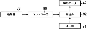
図12に示すように、カウンターウェイト台車40は、油圧式の駆動モータ42と、切換弁92と、油圧源91とを有している。
前記駆動モータ42は、油圧の供給を受けてカウンターウェイト台車40の車輪41を駆動する。
前記切換弁92は、油圧源91と駆動モータ42との間に設けられ、駆動モータ42への油圧の供給と、その停止を制御するための弁である。
クローラクレーン1においては、12に示すように、検知装置70の検知器73が、伸縮ビーム50のインナービーム51がアウタービーム52から抜け出す手前側の位置にあることを検知したとき、当該検知信号が、コントローラ90に入力される。検知器73からの検知信号を受けたコントローラ90は、切換弁92を中立位置に切り替えるよう指令を出す。
コントローラ90からの切り換え指令を受けた切換弁92は、駆動モータ42への油圧供給を遮断する。これにより、駆動モータ42の駆動が停止され、カウンターウェイト台車40の移動が停止される。
なお、本実施形態では、コントローラ90が検知器73からの検知信号を受けた場合、切換弁92を中立位置とする指令を出し、カウンターウェイト台車40の駆動モータ42の駆動を停止させることとしているが、次のような形態を採用することもできる。
先ず、クレーン本体10が、下部走行体12のクローラ11を駆動する駆動モータと、駆動モータに油圧を供給する油圧源と、駆動モータと油圧源との間に設けられた切換弁と、を有する形態を想定する。
そして、検知器73からの検知信号の入力を受けたコントローラ90は、クレーン本体10の切換弁に対して、切換弁を中立状態に切り替えるよう指令を出す。切り換え指令を受けた切換弁は、クレーン本体10の駆動モータへの油圧供給を遮断する。これにより、クレーン本体10の駆動が停止される。
以上のような形態では、クレーン本体10がカウンターウェイト台車40から遠ざかる方向に走行して伸縮ビーム50を伸長させている場合に、検知器73が伸縮ビーム50のインナービーム51がアウタービーム52から抜け出す手前側の位置にあることを検知したとき、クレーン本体10を停止させることができる。
7.伸縮ビーム抜け出し防止用検知装置70が奏する効果
以上説明したように、伸縮ビーム抜け出し防止用検知装置70は、上記構成の検知器73と、上記のように検知器73の位置をインナービーム51とアウタービーム52の間の隙間の変化に追従して変動させる変動機構74とを備える。
以上説明したように、伸縮ビーム抜け出し防止用検知装置70は、上記構成の検知器73と、上記のように検知器73の位置をインナービーム51とアウタービーム52の間の隙間の変化に追従して変動させる変動機構74とを備える。
この構成では、伸縮ビーム50のインナービーム51とアウタービーム52の間の隙間が製造時の公差や使用経年によるパッドなどの摩耗などで変化するときには、その変化に追従して、検知器73の位置が変動機構74により変動させる。換言すると、インナービーム51とアウタービーム52との隙間が変化した場合に、変動機構74は、伸縮ビーム50におけるインナービーム51及びアウタービーム52の断面方向に検知器73の位置を変動させる。これにより、検知器73とこれに対向するストライカー75側の筒状部材(インナービーム51)との間の所定の隙間を維持することができる。
本実施形態では、上記のような構成を備えることにより、検知器73の回転ローラ73dとこれに対向するインナービーム51とが所定の隙間を隔てて対向するようになる。このため、検知器73の回転ローラ73dとストライカー75との接触による検知を確実に行うことができるとともに、検知器73の回転ローラ73dなどがインナービーム51に直接当たって破損などをするのを防止することができる。
また、クローラクレーン1は、伸縮ビーム抜け出し防止用検知装置70を備える当たり、検知装置70の検知器73が、伸縮ビーム50のインナービーム51がアウタービーム52から抜け出す手前側の位置にあることを検知したとき、コントローラ90によりカウンターウェイト台車40又はクレーン本体10を停止させるように構成されている。このため、伸縮ビーム50のインナービーム51の抜け出しないし抜け落ちを防止することができる。
検知器73としては、接触式でも非接触式でもよいが、特に、本実施形態の場合、検知器73は、伸縮ビーム50のアウタービーム52に設置された接触式の検知器であるリミットスイッチからなり、インナービーム51に設けられたストライカー75に接触したときインナービーム51がアウタービーム52から抜け出す手前側の位置にあることを検知する。リミットスイッチからなる検知器73は、検知器が非接触式のものである場合に比べて、クローラクレーン1のように埃や風雨、温度変化などにさらされる屋外使用に適しており、検知器73の信頼性を高めることができる。
また、接触式の検知器73の使用は、検知器73が伸縮ビーム50の端部にあるような外部に近い程、つまり埃などの影響がでやすい位置にある程好ましい。
しかも、本実施形態では、検知器73が伸縮ビーム50のアウタービーム52に設置されているため、この検知器73の設置や検知器73に接続する信号線の配線作業などを比較的に容易に行うことができる。
また、変動機構74は、保持部材76と、4つの走行ローラ78,78,・・・と、2つの圧縮コイルばね79,79と、を有している。保持部材76は、上記のように、検知器73を保持する部材である。4つの走行ローラ78,78,・・は、保持部材76に取り付けられた接触部材又は転動子としての部材である。2つの圧縮コイルばね79,79は、保持部材76とアウタービーム52に固定した取付プレート72との間に介在された弾性体としての部材である。
各走行ローラ78は、インナービーム51に対し検知器73の回転ローラ73dが所定の隙間を隔てて対向するように転動可能に接触するようになっている。各圧縮コイルばね79は、各走行ローラ78をインナービーム51に常時接触させるように付勢している。
このような構成では、保持部材76に取り付けられた各走行ローラ78は、保持部材76と取付プレート72との間に介在された各圧縮コイルばね79の付勢力を受けてインナービーム51に常時接触した状態となっている。保持部材76に保持された検知器73の回転ローラ73dは、各走行ローラ78によりインナービーム51に対し所定の隙間を隔てて確実に対向するようになる。このため、変動機構74の動作の信頼性を高めることができる。
その上、接触部材又は転動子としての各走行ローラ78は、インナービーム51に対し転動可能に接触するようになっているため、この接触による各走行ローラ78などの摩耗を低減することができる。
なお、本実施形態では、変動機構74の取り付け位置は、エンドプレート67から離れた位置に設置されているが、エンドプレート67に近接した位置に設置してもよく、エンドプレート67に取付プレート72又は開口枠69を取り付けるようにしてもよい。この場合、伸縮ビーム50をできるだけ長く伸長させることができる。また、ストライカー75の位置を変えることでも伸縮ビーム50の伸長量を変えることが可能である。
[第2の実施形態]
本開示の第2の実施形態に係るクローラクレーンの構成の内、伸縮ビーム抜け出し防止用検知装置100の構成について、図13ないし図17を用い説明する。図13ないし図17は本実施形態に係るクローラクレーンの伸縮ビーム抜け出し防止用検知装置100の構成を示す。本実施形態の場合、伸縮ビーム50の構成は、第1の実施形態と略同じであり、同一部材には同一符号を付してその説明は省略する。
本開示の第2の実施形態に係るクローラクレーンの構成の内、伸縮ビーム抜け出し防止用検知装置100の構成について、図13ないし図17を用い説明する。図13ないし図17は本実施形態に係るクローラクレーンの伸縮ビーム抜け出し防止用検知装置100の構成を示す。本実施形態の場合、伸縮ビーム50の構成は、第1の実施形態と略同じであり、同一部材には同一符号を付してその説明は省略する。
1.伸縮ビーム抜け出し防止用検知装置100の概略構成
図13ないし図17に示すように、伸縮ビーム抜け出し防止用検知装置100は、取付プレート101と、2つの検知器102,102と、変動機構103と、を備えている。
図13ないし図17に示すように、伸縮ビーム抜け出し防止用検知装置100は、取付プレート101と、2つの検知器102,102と、変動機構103と、を備えている。
前記取付プレート101は、伸縮ビーム50のアウタービーム52の前端に設けたエンドプレート67に取り付けられている。
前記2つの検知器102,102は、取付プレート101に取り付けられている。各検知器102は、伸縮ビーム50のインナービーム51とアウタービーム52の間でインナービーム51がアウタービーム52から抜け出す手前側の位置(詳しくはアウタービーム52の前端側であるエンドプレート67の位置)に設置されている。
前記変動機構103は、取付プレート101を一つの構成部材としている。変動機構103は、各検知器102の位置を、インナービーム51とアウタービーム52の間の隙間の変化に追従して変動させるものである。
2.各部材の詳細構成
図14に示すように、取付プレート101は、各検知器102を保持する保持部材として、変動機構103の一つの構成部材を構成する。取付プレート101は、上辺部101aと、2つの側辺部101b,101bと、フランジ部101c,101cと、を有している。
図14に示すように、取付プレート101は、各検知器102を保持する保持部材として、変動機構103の一つの構成部材を構成する。取付プレート101は、上辺部101aと、2つの側辺部101b,101bと、フランジ部101c,101cと、を有している。
前記上辺部101aは、エンドプレート67の上枠部67aに対向している。
前記2つの側辺部101b,101bは、上辺部101aの左右両端からそれぞれ垂下してエンドプレート67の側方枠部67bの上部に対し、それぞれ対向している。
前記フランジ部101c,101cは、両側辺部101b,101bの下端部をそれぞれ略直角に折り曲げてなる。
図17に示すように、エンドプレート67の上枠部67aには左右2つの有底円筒状のタップドブロック104,104が固定されている。各タップドブロック104は、その中心線上にねじ穴105を有している。
一方、取付プレート101の上辺部101aには、タップドブロック104に対応して、左右2つの取付孔106,106が設けられている。各取付孔106の内径は、タップドブロック104の外径よりも大きいいわゆるばか孔に設定されている。
また、各タップドブロック104の中心線方向の長さ寸法は、取付プレート101の上辺部101aの厚み寸法よりも若干大きく設定されている。
取付プレート101の取付時には、先ず、各取付孔106にタップドブロック104を挿入した状態で取付プレート101をエンドプレート67に当接し又は近付ける。次に、この状態で取付孔106よりも大きいワッシャ107をそれぞれタップドブロック104の先端に当接する。その後、ボルト108のねじ部をワッシャ107の中心孔109を通してタップドブロック104のねじ穴105にねじ込む。
これにより、取付プレート101は、エンドプレート67に対し、その軸方向と直交する平面であるエンドプレート67に沿って移動可能な状態で、取り付けられている。そして、取付プレート101は、エンドプレート67を介して、アウタービーム52に取り付けられる。ただし、この移動は、取付プレート101がインナービーム51に直接接触しない範囲内に限定されている。
なお、タップドブロック104を設ける代わりに、次のような構成を採用することもできる。取付プレート101とエンドプレート67の上枠部67aとの間に、ワッシャ107と同様のワッシャを配置する。また、エンドプレート67の上枠部67aに貫通孔を設ける。次に、ボルト108のねじ部を、ワッシャ107の中心孔109、取付プレート101の取付孔106、前記ワッシャの中心孔及びエンドプレート67の上枠部67aの貫通孔を通す。そして、ボルト108のねじ部を、上枠部67aの取付プレート101と反対側の面にてナットで固定するようにしてもよい。
図14ないし図17に示すように、各検知器102は、第1の実施形態における検知器73と同じく、接触式の検知器であるリミットスイッチからなる。各検知器102は、検知器本体102aと、揺動レバー102cと、回転ローラ102dと、を有している。
前記検知器本体102aは、揺動レバー102c及び回転ローラ102dをインナービーム51の側壁部外面に向けた状態で、取付プレート101のフランジ部101cの上面に固定されている。
そして、各検知器102は、その回転ローラ102dがインナービーム51の側壁部外面に設けられた被検知部としてのストライカー110と接触したとき、インナービーム51がアウタービーム52から抜け出す手前側の位置にあることを検知する。
図14ないし図16に示すように、変動機構103は、各検知器102を保持する保持部材としての取付プレート101のほか、パッド111,111を有している。
パッド111,111は、取付プレート101の各側辺部101bの内縁にそれぞれ取り付けられた左右2つの接触子として設けられている。各パッド111は、自己潤滑性を有するナイロン樹脂などの合成樹脂からなる。各パッド111は、インナービーム51の対応する側面部に常に接触するようになっており、これにより、各パッド111に対応する検知器102の回転ローラ102dがインナービーム51に対し所定の隙間を隔てて対向するようになっている。
3.伸縮ビーム抜け出し防止用検知装置100が奏する効果
本実施形態においても、伸縮ビーム抜け出し防止用検知装置100は、上記構成の2つの検知器102,102と、各検知器102の位置をインナービーム51とアウタービーム52の間の隙間の変化に追従して変動させる変動機構103とを備える。このため、第1の実施形態の場合と同様な作用効果を奏することができる。
本実施形態においても、伸縮ビーム抜け出し防止用検知装置100は、上記構成の2つの検知器102,102と、各検知器102の位置をインナービーム51とアウタービーム52の間の隙間の変化に追従して変動させる変動機構103とを備える。このため、第1の実施形態の場合と同様な作用効果を奏することができる。
特に、本実施形態の変動機構103の場合、検知器102を保持する保持部材としての取付プレート101は、アウタービーム52に対しその軸方向と直交する平面であるエンドプレート67に沿って移動可能に取り付けられている。そして、この取付プレート101の各側辺部101bの内縁にそれぞれ取り付けられた左右2つのパッド111,111は、それぞれインナービーム51と常に接触している。各パッド111,111は、摺動子として設けられている。
このため、伸縮ビーム50のインナービーム51とアウタービーム52の間の隙間が製造時の公差や使用経年によるパッド111などの摩耗などで変化するときには、インナービーム51の動き(詳しくはインナービーム51のアウタービーム52に対する相対的な位置)に合わせて取付プレート101がエンドプレート67に沿って左右方向に移動する。この取付プレート101の移動により、取付プレート101の側辺部101bとインナービーム51との間の間隔は一定に維持される(図14~図16を参照)。これにより、各検知器102の回転ローラ102dは、インナービーム51とアウタービーム52の間の隙間の変化にかかわらず、インナービーム51に対し所定の隙間を隔てて確実に対向するようになる。このため、本実施形態に係る伸縮ビーム抜け出し防止用検知装置100では、変動機構103の動作の信頼性を高めることができる。
しかも、取付プレート101は、比較的に薄く軽い部材で構成されているため、インナービーム51との接触による抵抗力がほとんど生じることはなく、パッド111の摩耗の要因となる摩擦力も非常に小さくなる。このため、パッド111の摩耗がほとんど生じることはなく、取付プレート101の側辺部101bとインナービーム51との間の隙間を長期間に亘り一定に維持することができる。
ここで、本実施形態の場合、パッド111は、インナービーム51と常に接触している必要があるため、取付プレート101の側辺部101bからパッド111をボルトやバネによってインナービーム51に押し付けるような機構又は押し付け状態を調整する機構を設けることが好ましい。
また、取付プレート101の取付孔106とボルト108のねじ部との隙間は、インナービーム51とアウタービーム52との隙間と同じ、又はそれよりも大きな隙間となる。これは、インナービーム51とアウタービーム52との隙間の変動に合わせて取付プレート101がパッド111に接触していることによって動くことになるので、取付プレート101の取付孔106とボルト108のねじ部との隙間が小さいとインナービーム51とアウタービーム52との隙間の変動があっても、取付孔106とボルト108のねじ部が先に接触することで、追従できなくなることによる。
また、経年劣化や摩耗によるインナービーム51とアウタービーム52との隙間が広がることも勘案して取付プレート101の取付孔106とボルト108のねじ部との隙間を決める必要があり、例えば、取付孔106とボルト108のねじ部との隙間を摩耗等がされる分だけより大きめにしておくことが好ましい。
[第3の実施形態]
次に、本開示の第3の実施形態について、図18ないし図23を用い説明する。図18ないし図23は本実施形態に係るクローラクレーンの伸縮ビーム抜け出し防止用検知装置120の構成を示す。なお、本実施形態において、伸縮ビーム50の構成は、第1の実施形態の場合と略同じであり、同一部材には同一符号を付し、以下での説明は省略する。
次に、本開示の第3の実施形態について、図18ないし図23を用い説明する。図18ないし図23は本実施形態に係るクローラクレーンの伸縮ビーム抜け出し防止用検知装置120の構成を示す。なお、本実施形態において、伸縮ビーム50の構成は、第1の実施形態の場合と略同じであり、同一部材には同一符号を付し、以下での説明は省略する。
図18ないし図20に示すように、伸縮ビーム抜け出し防止用検知装置120は、伸縮ビーム50のアウタービーム52の前端に設けたエンドプレート67に取り付けられている。なお、本実施形態の場合、伸縮ビーム抜け出し防止用検知装置120は、エンドプレート67の一方の側方枠部67bの上部に取り付けられているが、エンドプレート67の他の部位に取り付けてもよい。
図18ないし図20に示すように、伸縮ビーム抜け出し防止用検知装置120は、ケース体121と、検知器122と、変動機構123と、を備えている。
ケース本体121は、エンドプレート67の前面側に取り付けられている。
図20及び図23に示すように、検知器122は、一部構成がケース本体121の内部に収納されている。図18及び図20に示すように、検知器122は、伸縮ビーム50のインナービーム51とアウタービーム52の間でインナービーム51がアウタービーム52から抜け出す手前側の位置に設置されている。より詳しくは、検知器122は、アウタービーム52の前端側であるエンドプレート67の位置に設置されている。
図20及び図23に示すように、変動機構123は、ケース本体121と検知器122との間に介在するよう設けられている。変動機構123は、検知器122の位置を、インナービーム51とアウタービーム52の間の隙間の変化に追従して変動させるものである。
図19ないし図23に示すように、ケース体121は、主側板124と、副側板125と、この両側板124,125間に配置された中間プレート126とからなる。中間プレート126は、主側板124及び副側板125に対し、それぞれ隅肉溶接などにより固着されている。
図21及び図23に示すように、主側板124は、エンドプレート67側に向かうに従って上下寸法が次第に大きくなる略等脚台形状に形成されている。主側板124には、エンドプレート67側端部の上下2箇所のそれぞれに、一対の挿入孔127,127が設けられている。ケース本体121は、各挿入孔127に挿入したボルトやねじ等の固定具128(図18及び図19を参照。)によりエンドプレート67に固定されている。
図21に示すように、副側板125は、矩形状に形成されている。この副側板125の上下寸法(短手方向長さ)は、主側板124の反エンドプレート側端の上下寸法と略同一になっている。副側板125の長手方向長さは、主側板124のそれと略同一になっている。
図23に示すように、中間プレート126は、上壁部126aと、下壁部126bと、奥壁部126cとを有している。奥壁部126cは、主側板124及び副側板125の反エンドプレート側端に沿って上下方向に延びている。上壁部126aは、奥壁部126cの上端から副側板125の上縁に沿って副側板125の長手方向中間位置にまで水平方向に延びている。下壁部126bは、奥壁部126cの下端から副側板125の下縁に沿って副側板125の長手方向中間位置にまで水平方向に延びている。下壁部126bの水平方向の長さは、上壁部126aのそれよりも長くなっている。
ケース体121は、以上のような構成から、エンドプレート67側に開放された収納部129を有している。
図20ないし図23に示すように、検知器122は、第1の実施形態における検知器73と同じく、接触式の検知器であるリミットスイッチからなる。そして、検知器122は、検知器本体122aと揺動レバー122cと回転ローラ122dとを有している。
検知器122の検知器本体122aは、揺動レバー122c及び回転ローラ122d をインナービーム51の側壁部外面に向けた状態で後述する保持部材131に固定されている。そして、検知器122は、その回転ローラ122dがインナービーム51の側壁部外面に設けられた被検知部としてのストライカーと接触し、揺動レバー122cが図20に仮想線で示す如く傾動したときインナービーム51がアウタービーム52から抜け出す手前側の位置にあることを検知する。
図23に示すように、変動機構123は、検知器122を保持する保持部材131を有している。保持部材131は、全体が略U字状に形成された板状の部材であって、上下一対の脚部131a,131aと、上下一対の脚部131a,131aの基端同士を連結する連結部131bとを有している。保持部材131の連結部131b及び各脚部131aの基端側は、ケース体121の収納部129内に水平方向に摺動可能に嵌合されている。換言すると、保持部材131の連結部131b及び各脚部131aの基端側は、ケース本体121の収納部129に対して、インナービーム51の側壁部に対し直交する方向に摺動可能な状態で嵌合されている。
この嵌合状態において、保持部材131の上側の脚部131aは、ケース体121の中間プレート126の上壁部126aの下面に摺動可能に接触している。また、保持部材131の下側の脚部131aは、ケース体121の中間プレート126の下壁部126bの上面に摺動可能に接触している。
図23に示すように、保持部材131の下側の脚部131aの内面側(上面側)には、検知器122の検知器本体122aが締結ボルトなどにより固定されている。図20に示すように、当該固定状態において、揺動レバー122c及び回転ローラ122dが、上下一対の脚部131a,131aの間でインナービーム51の側壁部外面に向けた状態となっている。
図23に示すように、変動機構123は、保持部材131の外に配置されている。変動機構123は、上下2つの走行ローラ133,133と、1つの圧縮コイルばね134と、を有している。上下一対の走行ローラ133,133は、保持部材131の各脚部131aの先端部にそれぞれ支軸132を介して回転自在に支持されている。各走行ローラ133は、いずれも接触部材又は転動子として、インナービーム51に対し検知器73の回転ローラ73dが所定の隙間を隔てて対向するように転動可能に接触している。
圧縮コイルばね134は、弾性体であり、保持部材131の連結部131bとケース体121の中間プレート126の奥壁部126cとの間に介在されている。圧縮コイルばね134は、後述する圧縮状態で、各走行ローラ133をインナービーム51に常時接触させるように付勢している。
なお、本実施形態の場合、ケース体121が、一方の筒状部材であるアウタービーム52に固定された「別の部材」に相当する。
また、図23に示すように、変動機構123は、保持部材131の連結部131bとケース体121の中間プレート126の奥壁部126cとの間に圧縮コイルばね134を介在させるに当たり、保持部材131がケース体121の収納部129内から抜け出るのを規制するためのねじ棒135及びナット136を用いている。
ねじ棒135は、ケース体121の中間プレート126の奥壁部126cに設けた挿入孔(ばか孔、図示を省略。)に挿入されている。ねじ棒135の一端部は、保持部材131の連結部131bに設けたねじ穴(図示を省略。)にねじ込まれた状態で溶接により固着されている。
また、図20に示すように、伸縮ビーム抜け出し防止用検知装置120の使用状態において、ねじ棒135の他端部に螺合されたナット136は、ケース体121の中間プレート126の奥壁部126cから離れた状態になる。この状態において、圧縮コイルばね134は、保持部材131の連結部131bとケース体121の中間プレート126の奥壁部126cとの間で圧縮され、この圧縮状態で付勢力(反力)を発生するようになっている。
なお、図20、図22及び図23に示すように、検知器122には、信号線141が接続されている。図23に示すように、信号線141は、ケース体121の主側板124に設けた導出口142を通してケース体121の外部に導出されている。
そして、本実施形態においても、伸縮ビーム抜け出し防止用検知装置120は、伸縮ビーム50のインナービーム51とアウタービーム52の間でインナービーム51がアウタービーム52から抜け出す手前側の位置に設置された検知器122と、この検知器122の位置を、インナービーム51とアウタービーム52の間の隙間の変化に追従して変動させる変動機構123とを備えるため、第1の実施形態の場合と同様な作用効果を奏することができる。
特に、本実施形態の変動機構123は、検知器122を保持する保持部材131と、この保持部材131に取り付けられた接触部材又は転動子としての2つの走行ローラ133,133と、保持部材131とアウタービーム52(詳しくはアウタービーム52の前端に設けたエンドプレート67)に固定したケース体121との間に介在された弾性体としての1つの圧縮コイルばね134とを有している。
各走行ローラ133は、インナービーム51に対し検知器122の回転ローラ122dが所定の隙間を隔てて対向するように転動可能に接触するようになっており、圧縮コイルばね134は、各走行ローラ133をインナービーム51に常時接触させるように付勢している。
このような構成を採用することにより、保持部材131に取り付けられた各走行ローラ133は、保持部材131とケース体121との間に介在された圧縮コイルばね134の付勢力を受けてインナービーム51に常時接触する。そして、保持部材131に保持された検知器122の回転ローラ122dは、各走行ローラ133によりインナービーム51に対し所定の隙間を隔てて確実に対向するようになる。このため、変動機構123の動作の信頼性を高めることができる。
さらに、本実施形態では、使用する走行ローラ133は2つだけであり、圧縮コイルばね134は1つだけである。このため、変動機構123の小型化を図ることができ、伸縮ビーム抜け出し防止用検知装置120の小型化を図ることができる。伸縮ビーム抜け出し防止用検知装置120の小型化を図ることに伴い、アウタービーム52の前端に設けたエンドプレート67にも伸縮ビーム抜け出し防止用検知装置120を容易に取り付けることができ、伸縮ビーム50をできるだけ長く伸長させることができる。
[変形例]
なお、本開示は上記第1ないし第3の実施形態に限定されるものではなく、その他種々の形態を包含するものである。例えば第1の実施形態では、伸縮ビーム50のアウタービーム52の前端側に接触式の検知器73を取り付ける一方、伸縮ビーム50のインナービーム51の後端側に被検知部としてのストライカー75を設けた。
なお、本開示は上記第1ないし第3の実施形態に限定されるものではなく、その他種々の形態を包含するものである。例えば第1の実施形態では、伸縮ビーム50のアウタービーム52の前端側に接触式の検知器73を取り付ける一方、伸縮ビーム50のインナービーム51の後端側に被検知部としてのストライカー75を設けた。
しかし、本開示は、これに限らず、例えばインナービーム51の後端側に接触式の検知器を取り付ける一方、アウタービーム52の前端側に被検知部を設けてもよい。
また、上記第1の実施形態では、変動機構74における接触部材の一例として、走行ローラ78を用いたが、本開示は、これに限定を受けるものではない。例えば、変形例として、走行ローラ78の代わり、又は走行ローラ78と併用して、スライド部材を用いてもよい。要は、接触部材としては、検知器73がインナービーム51に対し所定の間隔を隔てて対向するように転動可能又は摺動可能に接触し、かつ接触により伸縮ビーム50の伸縮に悪影響を及ぼさないようにすればよい。
同じく上記第1の実施形態では、変動機構74は、保持部材76の前後左右に4つの走行ローラ78,78,・・・と、保持部材76の前後に2つの圧縮コイルばね79,79とを有しており、検知器73は、保持部材76における前後2つの走行ローラ78,78間の中間位置に保持されている。これは、保持部材76が傾くなどして検知器73がインナービーム51に接触して反応しないように配慮したものである。
しかし、本開示は、これに限定を受けるものではない。例えば、変形例として、アウタービーム52に凹部を形成し、この凹部に、検知器を保持する保持部材を嵌め込んで配置することも可能である。この構成を採用する場合には、保持部材が傾くなどの動作を生じさせないようにすることにより、走行ローラ及び圧縮コイルばねをそれぞれ一つにすることができる。
また、上記第1及び第3の実施形態では、弾性体の一例として、圧縮コイルばね79を採用したが、本開示は、これに限定を受けるものではない。例えば、弾性体として、圧縮コイルばね以外のばね(例えば、板ばね、トーションバー、皿ばね、渦巻きばね、竹の子ばね、輪ばねなど)や、ゴムなどを用いてもよい。
上記第2の実施形態では、伸縮ビーム50のアウタービーム52の前端に設けたエンドプレート67に沿って取付プレート101を移動可能に取り付けるに当たり、取付プレート101の左右2つの取付孔106毎にその取付孔106よりも大きいワッシャ107を用いたが、本開示は、この構成に限定を受けるものではない。変形例として、例えば、ワッシャ107の代わりに、取付プレート101の左右2つの取付孔106,106を覆うプレートを用いてもよい。
また、上記第2の実施形態では、取付プレート101の取付孔106とタップドブロック104との間に弾性体を配置していないが、本開示は、この構成に限定を受けるものではない。変形例として、取付プレート101の取付孔106に、エンドプレート67に固定したタップドブロック104を挿入し、このタップドブロック104のねじ穴105にボルト108のねじ部をワッシャ107の中心孔109を通してねじ込んで固定するに当たり、取付プレート101の取付孔106とタップドブロック104との間に弾性体を配置してもよい。
なお、取付プレート101の取付孔106とタップドブロック104との間に弾性体を配置することとすれば、取付プレート101が中立位置に戻りやすくなり、組み立て時における高い作業性を確保するのに優位となる。即ち、弾性体の配置により、取付プレート101を中立位置に戻りやすくすることで、組立時に取付プレート101が簡単に動きすぎることを防ぐことができる。また、弾性体の配置により、取付プレート101の急激な移動により、ボルト108などと取付プレート101とが激しく衝突して破損するようなことも防ぐことができる。
取付プレート101の取付孔106とタップドブロック104との間に配置する弾性体として、粘弾性体(例えば、リング状のゴムや樹脂など)を採用することにすれば、上記のような作用効果をより確実に得ることができる。
同じく上記第2の実施形態では、取付プレート101の2箇所(各フランジ部101c)にそれぞれ検知器102を設けたが、本開示は、この構成に限定を受けるものではない。変形例として、例えば、取付プレート101の1箇所のみに検知器102を設けてもよいのは勿論である。
さらに、上記第2の実施形態では、取付プレート101はインナービーム51の上半部分を囲繞する形状に形成され、この取付プレート101の各側辺部101bの内縁にそれぞれ接触子としてのパッド111を取り付けた。
しかし、本開示は、この構成に限定を受けるものではない。変形例として、例えば、取付プレートを、インナービーム51の全周を囲繞する矩形枠状に形成し、この取付プレートの各枠部(上枠部、下枠部及び左右の側方枠部)の内縁にそれぞれ接触子を取り付ける、という構成を採用することができる。この構成を採用する場合、インナービーム51が左右方向に動いたときに取付プレートがそれに追従して移動するだけでなく、インナービーム51が上下方向に動いたときにも取付プレートがそれに追従して移動することになる。
加えて、上記第1ないし第3の実施形態では、いずれも伸縮ビーム50が2つの筒状部材(インナービーム51とアウタービーム52)を入れ子状に配置してなる場合について述べたが、本開示は、この構成に限定を受けるものではない。変形例として、例えば、伸縮ビームが3つ以上の筒状部材を入れ子状に配置してなる場合にも適用することができる。すなわち、この場合、3つ以上の筒状部材のうち、互いに内外に隣接する2つの筒状部材間では、一方の筒状部材が他方の筒状部材から抜け出す可能性がある。
このため、変形例としての伸縮ビーム抜け出し防止用検知装置として、例えば、伸縮ビームの互いに内外に隣接する2つの筒状部材間でかつ一方の筒状部材が他方の筒状部材から抜け出す手前側の位置に設置された検知器と、この検知器の位置を、前記2つの筒状部材間の隙間の変化に追従して変動させる変動機構とを備える構成にすることができる。ここで、一方の筒状部材が他方の筒状部材から抜け出す手前側の位置とは、隣接する2つの筒状部材のうち、クレーン本体に連結され若しくは近い側の筒状部材の後端側の位置、又はカウンターウェイト台車に連結され若しくは近い側の筒状部材の前端側の位置をいう。
また、上記第1ないし第3の実施形態では、筒状部材としては、四角形断面の筒状部材を採用したが、本開示は、この構成に限定を受けるものではない。変形例として、例えば、多角形、又は、丸形若しくは楕円形、長円形などの断面形状を有する筒状部材を採用することもできる。
さらに、上記第3の実施形態では、検知器122を保持する保持部材131を1つの部材により構成したが、本開示は、この構成に限定を受けるものではない。変形例として、例えば、複数の部材により構成することもできる。
また、上記第3の実施形態では、一方の筒状部材に固定される「別の部材」として、図18ないし図23に示すようなケース体121を採用したが、本開示は、この構成に限定を受けるものではない。変形例として、例えば中間プレートを2つ以上の部材で構成したり、ケース体を円筒状に形成したりしてもよい。
さらに、別の変形例として、「別の部材」を省略することもできる。このように、「別の部材」を省略した上で、保持部材と一方の筒状部材との間に圧縮コイルばねなどの弾性体を介在させ、この弾性体の付勢力により、保持部材に取り付けられた接触部材を他方の筒状部材に常時接触させるように構成してもよい。
また、上記第1ないし第3の実施形態では、「移動式クレーン」の一例としてクローラクレーンを採用したが、本開示は、これに限定を受けるものではない。変形例として、例えば、トラッククレーン、ホイールクレーン、鉄道クレーン、あるいは、水上の浮きクレーンなどを採用することもできる。これらのクレーンに対しても、上記同様の伸縮ビーム抜け出し防止用検知装置を採用することにより、上記と同様の効果を得ることができる。
[本開示の各態様]
以上の具体例を鑑み、本開示の各態様を纏めると次のようになる。
以上の具体例を鑑み、本開示の各態様を纏めると次のようになる。
(1)本開示の一態様に係る移動式クレーンの伸縮ビーム抜け出し防止用検知装置は、クレーン本体と自走式のカウンターウェイト台車とが伸縮ビームにより連結され、この伸縮ビームが、複数の筒状部材が入れ子状に配置されてなる移動式クレーンの伸縮ビームを検知対象とする。本態様に係る移動式クレーンの伸縮ビーム抜け出し防止用検知装置は、検知器と、変動機構と、を備える。
前記検知器は、前記伸縮ビームの断面方向において、互いに内外に隣接する第1及び第2の筒状部材間であって、かつ、前記伸縮ビームの伸縮方向において、前記第1の筒状部材が前記第2の筒状部材から抜け出す手前側の位置に少なくとも一部が設置されている。
前記変動機構は、前記伸縮ビームの断面方向における前記第1及び前記第2の筒状部材に対する検知器の位置を、前記伸縮ビームの断面方向における前記第1及び第2の筒状部材間の隙間の変化に追従して変動させる。
上記(1)の態様では、伸縮ビームの筒状部材間の隙間が製造時の公差や使用経年によるパッドなどの摩耗などで変化するときには、その変化に追従して、検知器の位置が変動機構により変動することにより、検知器とこれに対向する被検知部側の筒状部材とが所定の隙間を隔てて対向するようになる。換言すると、第1の筒状部材と第2の筒状部材との隙間が変化した場合に、前記変動機構は、前記伸縮ビームの断面方向に前記検知器の位置を変動させる。これにより、検知器とこれに対向する被検知部側の筒状部材との間の所定の隙間を維持する。
従って、上記(1)の態様では、確実に検知を行うことができ、また構成要素の破損を防止できる。
(2)本開示の別態様に係る伸縮ビーム抜け出し防止用検知装置は、上記構成において、前記検知器は、前記第1の筒状部材に設置されたものであって、前記第2の筒状部材に設けられた被検知部を検知したとき前記第1の筒状部材が前記第2の筒状部材から抜け出す手前側の位置にあることを検知するものである。
上記(2)の態様を採用する場合、特に、前記第1の筒状部材が前記第2の筒状部材に対して外側に配される筒状部材であり、前記第2の筒状部材が前記第1の筒状部材に対して内側に配される筒状部材である場合には、検知器の設置や検知器に接続する信号線の配線作業などを比較的に容易に行うことができる。
(3)本開示の別態様に係る伸縮ビーム抜け出し防止用検知装置は、上記構成において、前記変動機構は、保持部材と、接触部材と、弾性体と、を有している。
前記保持部材は、前記検知器を保持する。
前記接触部材は、前記保持部材に取り付けられ、前記伸縮ビームの断面方向において、前記第2の筒状部材に対し前記検知器が所定の隙間を隔てて対向するように転動可能又は摺動可能に接触する。
前記弾性体は、前記保持部材と前記第1の筒状部材又は当該筒状部材に固定された別の部材との間に介在され、前記接触部材を前記第2の筒状部材に常時接触させるように付勢する。
上記(3)の態様を採用する場合には、保持部材に取り付けられた接触部材が保持部材と前記第1の筒状部材又は当該第1の筒状部材に固定された別の部材との間に挿設された弾性体の付勢力(弾性反力)を受けて前記第2の筒状部材に常時接触し、保持部材に保持された検知器は、接触部材により前記第2の筒状部材に対し所定の隙間を隔てて確実に対向するようになる。よって、本態様を採用する場合には、上述のような、確実な検知と、構成要素の破損防止と、をより確実に奏することができる。
(4)本開示の別態様に係る伸縮ビーム抜け出し防止用検知装置は、上記構成において、前記接触部材は、前記第2の筒状部材に対し転動可能に接触する転動子からなる。
上記(4)の態様を採用する場合には、接触部材と前記第2の筒状部材との接触による摩耗を少なくすることができる。よって、長期の使用による接触部材の磨滅などを抑制でき、確実な検知を持続的に行うことができる。
(5)本開示の別態様に係る伸縮ビーム抜け出し防止用検知装置は、上記構成において、前記変動機構は、保持部材と、複数の接触子と、を有する。
前記保持部材は、前記第1の筒状部材に対しその軸方向と直交する平面に沿って移動可能に取り付けられ、前記検知器を保持する。
前記複数の接触子は、前記保持部材にそれぞれ取り付けられ、前記第2の筒状部材と常に接触して、前記検知器が前記第2の筒状部材に対し所定の隙間を隔てて対向するようにするための部材である。
上記(5)の態様を採用する場合には、検知器を保持する保持部材は、前記第1の筒状部材に対しその軸方向と直交する平面に沿って移動可能に取り付けられ、この保持部材にそれぞれ取り付けられた複数の接触子の各々は、前記第2の筒状部材と常に接触していることにより、検知器が前記第2の筒状部材に対し所定の隙間を隔てて確実に対向するようにできる。
(6)本開示の別態様に係る伸縮ビーム抜け出し防止用検知装置は、上記構成において、前記検知器は、接触式検知器である。
上記(6)の態様を採用する場合には、更に高い信頼性を得ることができる。即ち、接触式検知器は埃や風雨などにさらされる屋外使用に適しており、該接触式検知器を前記検知器として採用する本態様では、更に高い信頼性を得ることができる。
(7)本開示の一態様に係る移動式クレーンは、クレーン本体と、カウンターウェイト台車と、伸縮ビームと、検知器と、変動機構と、コントローラと、を備える。
前記伸縮ビームは、前記クレーン本体と前記カウンターウェイト台車とを連結し、複数の筒状部材が入れ子状に配置されてなる。
前記検知器は、前記伸縮ビームの断面方向において、互いに内外に隣接する第1及び第2の筒状部材間であって、かつ、前記伸縮ビームの伸縮方向において、前記第1の筒状部材が前記第2の筒状部材から抜け出す手前側の位置に少なくとも一部が設置され、前記第1の筒状部材が前記第2の筒状部材から抜け出す手前側の位置にあることを検知する。
前記変動機構は、前記伸縮ビームの断面方向における前記第1及び前記第2の筒状部材に対する検知器の位置を、前記伸縮ビームの断面方向における前記第1及び第2の筒状部材間の隙間の変化に追従して変動させる。
前記コントローラは、前記検知器が前記第1の筒状部材が前記第2の筒状部材から抜け出す手前側の位置にあることを検知したとき、前記カウンターウェイト台車及び前記クレーン本体の少なくとも一方を停止させる。
上記(7)の態様では、伸縮ビームの筒状部材間の隙間が製造時の公差や使用経年によるパッドなどの摩耗などで変化するときには、その変化に追従して、検知器の位置が変動機構により変動することにより、検知器とこれに対向する筒状部材とが所定の隙間を隔てて対向するようになる。このため、検知器による検知を行うことができるとともに、検知器が対向する被検知部側の筒状部材に直接当たって破損などをするのを防止できる。
換言すると、第1の筒状部材と第2の筒状部材との隙間が変化した場合に、前記変動機構は、前記伸縮ビームの断面方向に前記検知器の位置を変動させる。これにより、検知器とこれに対向する被検知部側の筒状部材との間の所定の隙間を維持する。
しかも、検知器が伸縮ビームの筒状部材間で一方の筒状部材が他方の筒状部材から抜け出す手前側の位置にあることを検知したとき、前記コントローラが自走式のカウンターウェイト台車又はクレーン本体を停止させるので、伸縮ビームの抜け出しないし抜け落ちを防止することができる。
Claims (7)
- クレーン本体と自走式のカウンターウェイト台車とが伸縮ビームにより連結され、この伸縮ビームは、複数の筒状部材が入れ子状に配置されてなる移動式クレーンの伸縮ビーム抜け出し防止用検知装置において、
前記伸縮ビームの断面方向において、互いに内外に隣接する第1及び第2の筒状部材間であって、かつ、前記伸縮ビームの伸縮方向において、前記第1の筒状部材が前記第2の筒状部材から抜け出す手前側の位置に少なくとも一部が設置された検知器と、
前記伸縮ビームの断面方向における前記第1及び前記第2の筒状部材に対する検知器の位置を、前記伸縮ビームの断面方向における前記第1及び第2の筒状部材間の隙間の変化に追従して変動させる変動機構と、
を備える、
移動式クレーンの伸縮ビーム抜け出し防止用検知装置。 - 前記検知器は、前記第1の筒状部材に設置されたものであって、前記第2の筒状部材に設けられた被検知部を検知したとき前記第1の筒状部材が前記第2の筒状部材から抜け出す手前側の位置にあることを検知するものである、
請求項1記載の移動式クレーンの伸縮ビーム抜け出し防止用検知装置。 - 前記変動機構は、前記検知器を保持する保持部材と、該保持部材に取り付けられ、前記伸縮ビームの断面方向において、前記第2の筒状部材に対し前記検知器が所定の隙間を隔てて対向するように転動可能又は摺動可能に接触する接触部材と、前記保持部材と前記第1の筒状部材又は当該筒状部材に固定された別の部材との間に挿設され、前記接触部材を前記第2の筒状部材に常時接触させるように付勢する弾性体とを有している、
請求項2記載の移動式クレーンの伸縮ビーム抜け出し防止用検知装置。 - 前記接触部材は、前記第2の筒状部材に対し転動可能に接触する転動子からなる、
請求項3記載の移動式クレーンの伸縮ビーム抜け出し防止用検知装置。 - 前記変動機構は、前記第1の筒状部材に対しその軸方向と直交する平面に沿って移動可能に取り付けられ、前記検知器を保持する保持部材と、該保持部材にそれぞれ取り付けられ、前記第2の筒状部材と常に接触して前記検知器が前記第2の筒状部材に対し所定の隙間を隔てて対向するようにするための複数の接触子とを有している、
請求項2記載の移動式クレーンの伸縮ビーム抜け出し防止用検知装置。 - 前記検知器は、接触式検知器である、
請求項1ないし請求項5のいずれか一項に記載の移動式クレーンの伸縮ビーム抜け出し防止用検知装置。 - クレーン本体と、
カウンターウェイト台車と、
前記クレーン本体と前記カウンターウェイト台車とを連結し、複数の筒状部材が入れ子状に配置されてなる伸縮ビームと、
前記伸縮ビームの断面方向において、互いに内外に隣接する第1及び第2の筒状部材間であって、かつ、前記伸縮ビームの伸縮方向において、前記第1の筒状部材が前記第2の筒状部材から抜け出す手前側の位置に少なくとも一部が設置され、前記第1の筒状部材が前記第2の筒状部材から抜け出す手前側の位置にあることを検知する検知器と、
前記伸縮ビームの断面方向における前記第1及び前記第2の筒状部材に対する検知器の位置を、前記伸縮ビームの断面方向における前記第1及び第2の筒状部材間の隙間の変化に追従して変動させる変動機構と、
前記検知器が前記第1の筒状部材が前記第2の筒状部材から抜け出す手前側の位置にあることを検知したとき、前記カウンターウェイト台車及び前記クレーン本体の少なくとも一方を停止させるコントローラと、
を備える移動式クレーン。
Applications Claiming Priority (4)
| Application Number | Priority Date | Filing Date | Title |
|---|---|---|---|
| JP2015-202385 | 2015-10-13 | ||
| JP2015202385 | 2015-10-13 | ||
| JP2016-091569 | 2016-04-28 | ||
| JP2016091569A JP6288154B2 (ja) | 2015-10-13 | 2016-04-28 | 移動式クレーンの伸縮ビーム抜け出し防止用検知装置及び移動式クレーン |
Publications (1)
| Publication Number | Publication Date |
|---|---|
| WO2017064966A1 true WO2017064966A1 (ja) | 2017-04-20 |
Family
ID=58517675
Family Applications (1)
| Application Number | Title | Priority Date | Filing Date |
|---|---|---|---|
| PCT/JP2016/076887 Ceased WO2017064966A1 (ja) | 2015-10-13 | 2016-09-13 | 移動式クレーンの伸縮ビーム抜け出し防止用検知装置及び移動式クレーン |
Country Status (1)
| Country | Link |
|---|---|
| WO (1) | WO2017064966A1 (ja) |
Cited By (1)
| Publication number | Priority date | Publication date | Assignee | Title |
|---|---|---|---|---|
| CN116177423A (zh) * | 2023-03-29 | 2023-05-30 | 湖南三一中型起重机械有限公司 | 配重变位装置及作业机械 |
Citations (5)
| Publication number | Priority date | Publication date | Assignee | Title |
|---|---|---|---|---|
| JPS59207394A (ja) * | 1983-05-11 | 1984-11-24 | 株式会社神戸製鋼所 | 超大型クレ−ン |
| JPH08133680A (ja) * | 1994-11-15 | 1996-05-28 | Komatsu Ltd | クレーンのブーム位置検出装置 |
| JP2000198674A (ja) * | 1998-09-11 | 2000-07-18 | Liebherr Werk Ehingen Gmbh | クレ―ン |
| JP2011207598A (ja) * | 2010-03-30 | 2011-10-20 | Tadano Ltd | ブーム及びクレーン |
| US20120160796A1 (en) * | 2010-12-22 | 2012-06-28 | Terex Demag Gmbh | Crane and method for operating a crane using recovery of energy from crane operations as a secondary energy source |
-
2016
- 2016-09-13 WO PCT/JP2016/076887 patent/WO2017064966A1/ja not_active Ceased
Patent Citations (5)
| Publication number | Priority date | Publication date | Assignee | Title |
|---|---|---|---|---|
| JPS59207394A (ja) * | 1983-05-11 | 1984-11-24 | 株式会社神戸製鋼所 | 超大型クレ−ン |
| JPH08133680A (ja) * | 1994-11-15 | 1996-05-28 | Komatsu Ltd | クレーンのブーム位置検出装置 |
| JP2000198674A (ja) * | 1998-09-11 | 2000-07-18 | Liebherr Werk Ehingen Gmbh | クレ―ン |
| JP2011207598A (ja) * | 2010-03-30 | 2011-10-20 | Tadano Ltd | ブーム及びクレーン |
| US20120160796A1 (en) * | 2010-12-22 | 2012-06-28 | Terex Demag Gmbh | Crane and method for operating a crane using recovery of energy from crane operations as a secondary energy source |
Cited By (1)
| Publication number | Priority date | Publication date | Assignee | Title |
|---|---|---|---|---|
| CN116177423A (zh) * | 2023-03-29 | 2023-05-30 | 湖南三一中型起重机械有限公司 | 配重变位装置及作业机械 |
Similar Documents
| Publication | Publication Date | Title |
|---|---|---|
| US8813981B2 (en) | Anti-two block system for a crane assembly | |
| JP4840256B2 (ja) | カウンタバランス型クレーン | |
| CN201659860U (zh) | 车辆悬架系统刚性锁定机构 | |
| CN105246818B (zh) | 用于在地面上支承移动装置的装置 | |
| JP2005528304A (ja) | クレーンアセンブリ | |
| CN102020211A (zh) | 平衡装置及包含该平衡装置的起重机 | |
| KR101387337B1 (ko) | 판타 그라프 슈 편마모 방지장치 및 그 방법 | |
| KR101201878B1 (ko) | 건설용 중량구조물 이송용 전동리프트 | |
| JP6565123B2 (ja) | オートテンション機能を有するウインチ装置 | |
| CN103130110A (zh) | 移动式作功机械、特别是车辆起重机 | |
| JP6391019B2 (ja) | 脱輪防止装置 | |
| CN107207225A (zh) | 起重机、用于偏转起重机上的力的装置和方法 | |
| JP6288154B2 (ja) | 移動式クレーンの伸縮ビーム抜け出し防止用検知装置及び移動式クレーン | |
| CN215803580U (zh) | 一种阻挡装置 | |
| WO2017064966A1 (ja) | 移動式クレーンの伸縮ビーム抜け出し防止用検知装置及び移動式クレーン | |
| KR101173130B1 (ko) | 크레인 사고 방지방법 | |
| KR100766540B1 (ko) | 하역장비용 바퀴 고정장치 | |
| JP3600554B2 (ja) | 軌条走行式荷役機械の免震装置 | |
| JP4538309B2 (ja) | 軌陸作業車 | |
| JP2017121693A (ja) | ブームを備えた走行装置及びブームロック方法 | |
| CN221318983U (zh) | 一种起重机的紧急制动装置 | |
| KR101173136B1 (ko) | 크레인 붐 충돌방지 스토퍼 장치 | |
| CN224017225U (zh) | 一种底部可通车的隧道衬砌台车 | |
| KR102865641B1 (ko) | 자동차 정비용 인양 제어 및 모니터링 시스템 | |
| KR20220017126A (ko) | 이동식 다목적 미니 갠트리 크레인 |
Legal Events
| Date | Code | Title | Description |
|---|---|---|---|
| 121 | Ep: the epo has been informed by wipo that ep was designated in this application |
Ref document number: 16855220 Country of ref document: EP Kind code of ref document: A1 |
|
| NENP | Non-entry into the national phase |
Ref country code: DE |
|
| 122 | Ep: pct application non-entry in european phase |
Ref document number: 16855220 Country of ref document: EP Kind code of ref document: A1 |