WO2017057548A1 - 研削盤 - Google Patents
研削盤 Download PDFInfo
- Publication number
- WO2017057548A1 WO2017057548A1 PCT/JP2016/078782 JP2016078782W WO2017057548A1 WO 2017057548 A1 WO2017057548 A1 WO 2017057548A1 JP 2016078782 W JP2016078782 W JP 2016078782W WO 2017057548 A1 WO2017057548 A1 WO 2017057548A1
- Authority
- WO
- WIPO (PCT)
- Prior art keywords
- spindle
- wafer
- grindstone
- feed mechanism
- grinding
- Prior art date
- Legal status (The legal status is an assumption and is not a legal conclusion. Google has not performed a legal analysis and makes no representation as to the accuracy of the status listed.)
- Ceased
Links
Images



Classifications
-
- B—PERFORMING OPERATIONS; TRANSPORTING
- B24—GRINDING; POLISHING
- B24B—MACHINES, DEVICES, OR PROCESSES FOR GRINDING OR POLISHING; DRESSING OR CONDITIONING OF ABRADING SURFACES; FEEDING OF GRINDING, POLISHING, OR LAPPING AGENTS
- B24B7/00—Machines or devices designed for grinding plane surfaces on work, including polishing plane glass surfaces; Accessories therefor
- B24B7/04—Machines or devices designed for grinding plane surfaces on work, including polishing plane glass surfaces; Accessories therefor involving a rotary work-table
-
- B—PERFORMING OPERATIONS; TRANSPORTING
- B24—GRINDING; POLISHING
- B24B—MACHINES, DEVICES, OR PROCESSES FOR GRINDING OR POLISHING; DRESSING OR CONDITIONING OF ABRADING SURFACES; FEEDING OF GRINDING, POLISHING, OR LAPPING AGENTS
- B24B37/00—Lapping machines or devices; Accessories
- B24B37/005—Control means for lapping machines or devices
-
- B—PERFORMING OPERATIONS; TRANSPORTING
- B24—GRINDING; POLISHING
- B24B—MACHINES, DEVICES, OR PROCESSES FOR GRINDING OR POLISHING; DRESSING OR CONDITIONING OF ABRADING SURFACES; FEEDING OF GRINDING, POLISHING, OR LAPPING AGENTS
- B24B41/00—Component parts such as frames, beds, carriages, headstocks
- B24B41/04—Headstocks; Working-spindles; Features relating thereto
- B24B41/047—Grinding heads for working on plane surfaces
-
- B—PERFORMING OPERATIONS; TRANSPORTING
- B24—GRINDING; POLISHING
- B24B—MACHINES, DEVICES, OR PROCESSES FOR GRINDING OR POLISHING; DRESSING OR CONDITIONING OF ABRADING SURFACES; FEEDING OF GRINDING, POLISHING, OR LAPPING AGENTS
- B24B47/00—Drives or gearings; Equipment therefor
- B24B47/10—Drives or gearings; Equipment therefor for rotating or reciprocating working-spindles carrying grinding wheels or workpieces
- B24B47/14—Drives or gearings; Equipment therefor for rotating or reciprocating working-spindles carrying grinding wheels or workpieces by liquid or gas pressure
-
- B—PERFORMING OPERATIONS; TRANSPORTING
- B24—GRINDING; POLISHING
- B24B—MACHINES, DEVICES, OR PROCESSES FOR GRINDING OR POLISHING; DRESSING OR CONDITIONING OF ABRADING SURFACES; FEEDING OF GRINDING, POLISHING, OR LAPPING AGENTS
- B24B49/00—Measuring or gauging equipment for controlling the feed movement of the grinding tool or work; Arrangements of indicating or measuring equipment, e.g. for indicating the start of the grinding operation
- B24B49/08—Measuring or gauging equipment for controlling the feed movement of the grinding tool or work; Arrangements of indicating or measuring equipment, e.g. for indicating the start of the grinding operation involving liquid or pneumatic means
-
- B—PERFORMING OPERATIONS; TRANSPORTING
- B24—GRINDING; POLISHING
- B24B—MACHINES, DEVICES, OR PROCESSES FOR GRINDING OR POLISHING; DRESSING OR CONDITIONING OF ABRADING SURFACES; FEEDING OF GRINDING, POLISHING, OR LAPPING AGENTS
- B24B49/00—Measuring or gauging equipment for controlling the feed movement of the grinding tool or work; Arrangements of indicating or measuring equipment, e.g. for indicating the start of the grinding operation
- B24B49/16—Measuring or gauging equipment for controlling the feed movement of the grinding tool or work; Arrangements of indicating or measuring equipment, e.g. for indicating the start of the grinding operation taking regard of the load
-
- H—ELECTRICITY
- H10—SEMICONDUCTOR DEVICES; ELECTRIC SOLID-STATE DEVICES NOT OTHERWISE PROVIDED FOR
- H10P—GENERIC PROCESSES OR APPARATUS FOR THE MANUFACTURE OR TREATMENT OF DEVICES COVERED BY CLASS H10
- H10P52/00—Grinding, lapping or polishing of wafers, substrates or parts of devices
Definitions
- the present invention relates to a grinder that grinds the back surface of a wafer, and more particularly, to a grinder that can grind a brittle wafer without damaging it.
- wafer such as a silicon wafer (hereinafter referred to as “wafer”) into a thin film
- backside grinding is performed by grinding the backside of the wafer.
- the posture of the spindle 43 may be tilted by a reaction force during grinding, and the wafer W cannot be processed into a desired cross-sectional shape. There is a possibility that a so-called eyelet is formed on the back surface of the wafer W and damages the wafer W.
- a semiconductor mechanism is provided by moving a grinding mechanism holding a grinding member in a horizontal direction and a guide for sliding the grinding mechanism to the semiconductor substrate at a constant speed.
- a semiconductor substrate grinder comprising: a constant speed moving mechanism for grinding a semiconductor substrate; and a constant pressure moving mechanism for moving the grinding mechanism to the semiconductor substrate so that the semiconductor substrate and the grinding mechanism are pressed at a constant pressure after grinding by the constant speed moving mechanism Is disclosed.
- Patent Document 2 there is provided a grinding machine in which a grinding wheel is provided so as to be slidable in a vertical direction via a linear guide, and the grinding wheel is lowered according to a desired grinding amount to infeed grinding the back surface of the wafer. It is disclosed.
- JP 2009-272323 A Japanese Patent No. 5582916
- the grindstone is a so-called reservoir due to the sliding resistance generated in the guide when the guide approaches the wafer. Since it moves by feeding, it was difficult to cut the wafer with a fine grinding amount. If the cutting depth of the grindstone (abrasive grain) is larger than the critical cutting depth (Dc value) of the wafer, as shown in FIG. 7, brittle mode grinding in which the wafer is chipped or cracked during grinding of the wafer. There was a risk of becoming.
- the point that supports the grindstone is separated from the working point to be processed and is often a cantilever type.
- a cantilever type even if it is pressed at a constant pressure according to the sharpness of the abrasive grains at the tip of the grindstone, since it is a cantilever type, one of the grindstones is lifted and the grindstone itself is not parallel to the wafer. .
- an excessive force is applied to a local portion, and a portion where the tip of the abrasive grain is largely cut into the wafer is generated, thereby causing a crack.
- the wafer is stably ground by suppressing brittle mode grinding, and the present invention aims to solve this problem.
- the present invention has been proposed in order to achieve the above object, and the invention according to claim 1 is characterized in that a grindstone for grinding a wafer is attached to a lower end and the spindle is rotatable, and the grindstone grinds the wafer.
- At least two vertically extending linear guides arranged on the outer periphery of the spindle so as to sandwich a point and slidably supporting the spindle with respect to a column; and a spindle feed mechanism for feeding the spindle vertically downward;
- a grinding machine that processes the wafer with the grindstone while feeding the spindle in the vertical direction, and is interposed between the spindle feed mechanism and the column, and the spindle feed mechanism transfers the grindstone to the wafer.
- the spindle and the spindle feed mechanism are raised when a frictional force of a predetermined value or more is applied to the grindstone.
- the constant pressure feed mechanism temporarily raises the spindle and the spindle feed mechanism when the grindstone tries to cut deeper than the desired grinding amount and the frictional force acting on the grindstone is excessive.
- the wafer is subjected to ductile mode grinding in a state where the grinding wheel and the wafer are not excessively contacted, that is, the so-called spindle is floated, stable grinding can be performed without damaging the wafer.
- the grindstone and the spindle are lowered along the direction of gravity and force is applied to the wafer. Even if the sharpness of the tip of the grindstone changes, since the wafer is pressed with a constant pressure, a cut corresponding to the sharpness is given to the wafer. This makes it possible to give a cut to the wafer while feeding the grindstone at a predetermined pressure according to the sharpness of the grindstone, compared to the conventional method of feeding the grindstone at a constant speed, giving a stable cut and cracking. Can be suppressed. In addition, since the grindstone is automatically sent according to the speed at which the actual wafer is removed by the processing, it is possible to continue the constant incision processing stably during the processing.
- the at least two linear guides are arranged so as to sandwich the processing point, even if the grindstone receives a reaction force accompanying the processing from the wafer, the grindstone is inclined by the reaction force. Instead, the wheel is always parallel to the wafer by being pushed back vertically upward, and the horizontal state can be maintained. Thereby, it is possible to continuously give a constant cut while suppressing an excessive processing stress in a part of the grindstone.
- the constant pressure feeding mechanism provides a grinding machine which is a constant pressure cylinder.
- the constant pressure cylinders are respectively provided on both sides in the horizontal direction perpendicular to the vertical direction across the spindle feed mechanism. I will provide a.
- the constant pressure cylinders provided on both sides in the horizontal direction of the spindle feed mechanism are similarly driven when the spindle and the spindle feed mechanism are raised.
- the spindle and the spindle feed mechanism are restricted from moving in the horizontal direction, ductile mode grinding with the spindle floating can be stably performed.
- the driving pressure of the constant pressure cylinder acts on the grindstone when the grindstone is cut by a critical cut depth of the wafer.
- a grinding machine which is set to a value equal to or less than a value corresponding to a frictional force.
- the feed direction in which the spindle feed mechanism feeds the spindle is that the grindstone is along the vertical direction.
- a grinding machine arranged on a straight line passing through a processing point for grinding a wafer.
- the feeding direction is parallel to the vertical direction and is arranged on a straight line passing through the processing point of the grindstone.
- the spindle feed mechanism feeds the spindle so as to suppress the reaction force when the grindstone contacts the wafer, so ductile mode grinding with the spindle floating is performed. It can be performed stably.
- At least three linear guides are provided, and the center of gravity of the spindle is the linear guide in a plan view.
- a grinding machine disposed within a polygon formed by the above is provided.
- the center of gravity of the spindle is disposed within the polygon formed by the linear guide, whereby the frictional force acting on the grindstone.
- the linear guide placed around the spindle regulates the attitude of the spindle and the spindle yaws, chips or rolls against the grinding machine In order to regulate this, ductile mode grinding with the spindle floating can be performed stably.
- the constant pressure feed mechanism temporarily raises the spindle and the spindle feed mechanism, Since the wafer is subjected to ductile mode grinding with the spindle floating, the wafer can be stably ground without damaging the wafer.
- a constant pressure is given by the natural weight, a constant pressure is always applied to the wafer surface corresponding to the sharpness of the abrasive grain tip, and cracks occur in the wafer while maintaining a constant cutting depth. It is possible to perform grinding in a ductile mode while maintaining a not-so-deadly depth of cut.
- the perspective view which shows the grinding machine which concerns on one Example of this invention The top view of the main unit shown in FIG. The side view of the main unit shown in FIG. The perspective view which shows the upper part of a main unit.
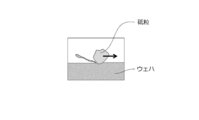
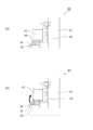
- the schematic diagram which shows the mode of ductile mode grinding It is a schematic diagram which shows the conventional grinding machine, (a) is a figure which shows the mode before grinding, (b) is a figure which shows the mode during grinding.
- the grinding machine In order to achieve the object of stably grinding a wafer by suppressing brittle mode grinding, the grinding machine according to the present invention has a grindstone for grinding a wafer attached to the lower end and a rotatable spindle, and the grindstone holds the wafer.
- At least two vertically extending linear guides arranged on the outer periphery of the spindle so as to sandwich the processing point to be ground, and slidably supporting the spindle with respect to the column; a spindle feed mechanism for feeding the spindle vertically downward;
- a grinding machine that processes a wafer with a grinding wheel while feeding the spindle in the vertical direction, and is interposed between the spindle feeding mechanism and the column, suspending the spindle and the spindle feeding mechanism, and the spindle feeding mechanism When the grinding wheel is cut into the wafer and a frictional force greater than the specified value is applied to the grinding wheel, the spindle and spindle feed mechanism are raised. Realized by that it comprises a pressure feed mechanism for.
- the grinding machine according to the present invention is not particularly limited as long as the grindstone grinds the wafer in a ductile mode in a floating state in which the spindle is not excessively in contact with the wafer without grinding with a cutting depth greater than the critical cutting depth of the wafer. Any particular embodiment may be used.
- the terms “upper” and “lower” correspond to the upper and lower parts in the vertical direction.
- FIG. 1 is a perspective view showing a basic configuration of a grinding machine 1 in which a constant pressure feeding mechanism is omitted.
- FIG. 2 is a plan view of the main unit 2 shown in FIG.
- FIG. 3 is a side view of the main unit 2.
- FIG. 4 is a perspective view showing the upper part of the main unit 2.
- the grinding machine 1 forms a thin film by grinding the back surface of the wafer W.
- the wafer W to be ground using the grinder 1 is preferably a silicon wafer, silicon carbide wafer, or the like that exhibits high hardness and high brittleness, but is not limited thereto.
- the grinding machine 1 includes a main unit 2 including a grindstone 21 and a transport unit 3 disposed below the main unit 2.
- the main unit 2 includes an arched column 22, a spindle 23 to which a grindstone 21 is attached, three linear guides 24 that support the spindle 23 so as to be slidable in the vertical direction V, and the spindle 23 is moved up and down in the vertical direction V.
- a spindle feed mechanism 25 to be moved.
- the transfer unit 3 includes a chuck 31 that can hold the wafer W by suction and a slider 32 on which the chuck 31 is placed.
- the chuck 31 is connected to a vacuum source (not shown) and can vacuum-suck the wafer W onto the surface of the chuck 31. Further, the chuck 31 can be rotated around a vertical axis passing through the center of the chuck 31 by a motor (not shown).
- the slider 32 is slidable on the rail 33 by a slider drive mechanism (not shown), whereby the chuck 31 and the slide 32 are integrally slid in the wafer transfer direction D1.
- the wafer W vacuum-sucked on the chuck 31 is carried to the lower part of the grindstone 21 by the slider 32 before the grinding process, and is carried out from the lower part of the grindstone 21 to the rear of the main unit 2 after the grinding process.
- the operation of the grinding machine 1 is controlled by a control unit (not shown).
- the control unit controls each component constituting the grinding machine 1.
- the control unit includes, for example, a CPU, a memory, and the like.
- the function of the control unit may be realized by controlling using software, or may be realized by operating using hardware.
- the spindle 23 is accommodated in a groove 22 b that is recessed in the front surface 22 a of the column 22 in the vertical direction V.
- the spindle 23 includes a saddle 23a with the grindstone 21 attached to the lower end, and a motor 23b that is provided in the saddle 23a and rotates the grindstone 21.
- the linear guide 24 includes two front linear guides 24a disposed in front of the column 22 and one rear linear guide 24b disposed in the groove 22b.
- the front linear guide 24a and the rear linear guide 24b are provided in parallel to each other along the vertical direction V.
- a saddle 23a is directly attached to the front linear guide 24a.
- a saddle 23a is attached to the rear linear guide 24b via a nut 25a described later. Accordingly, the front linear guide 24a and the rear linear guide 24b function as guide rails for the saddle 23a.
- the front linear guide 24a is disposed at the edge of the groove 22b.
- the rear linear guide 24b is disposed at the bottom of the groove 22b.
- the front linear guide 24a and the rear linear guide 24b are arranged such that the center of gravity G of the spindle 23 is arranged in a triangle T formed by the front linear guide 24a and the rear linear guide 24b in plan view. Are spaced apart from each other.
- the spindle feed mechanism 25 includes a nut 25a that connects the saddle 23a and the rear linear guide 24b, a ball screw 25b that moves the nut 25a up and down, and a motor 25c that rotates the ball screw 25b.
- the motor 25c is driven to rotate the ball screw 25b in the forward direction and the nut 25a is lowered in the feeding direction D2 of the ball screw 25b parallel to the vertical direction V, the saddle 23a is lowered.
- the feeding direction D2 is on a straight line parallel to the vertical direction V through the processing point P where the grindstone 21 processes the wafer W.
- the rotation axis O of the ball screw 25b and the processing point P of the grindstone 21 are arranged on the same straight line in the vertical direction V.
- the spindle 23 and the spindle feed mechanism 25 are connected to a counterweight (not shown), and are suspended from a constant pressure cylinder 26, which will be described later, in balance with the counterweight. Thereby, the spindle feed mechanism 25 can lower the spindle 23 to the grinding start position at high speed. Further, the grinding wheel 21 is cut into the wafer W by the amount that the spindle feed mechanism 25 sends the spindle 23, and the feed amount of the spindle feed mechanism 25 can be accurately grasped by the rotation amount of the ball screw 25b. Can be controlled with high accuracy.
- the main unit 2 is provided with an in-process gauge (not shown) for measuring the thickness of the wafer W.
- an in-process gauge (not shown) for measuring the thickness of the wafer W.
- the main unit 2 is provided with a constant pressure cylinder 26 as a constant pressure feeding mechanism.
- a constant pressure cylinder 26 is provided on each side of the horizontal direction H across the nut 25a of the spindle feed mechanism 25, and is interposed between the column 22 and the nut 25a.
- the constant pressure cylinder 26 is an air cylinder that employs a known configuration including a cylinder, a piston, a piston rod, a compressor, and the like (not shown).
- the driving pressure of the constant pressure cylinder 26 is set to a value corresponding to the frictional force acting on the grindstone 21 when the grindstone 21 is cut by the critical cutting depth (Dc value) of the wafer W.
- the Dc value varies depending on the material of the wafer W, and is 0.09 ⁇ m for a silicon wafer and 0.15 ⁇ m for a silicon carbide wafer, for example.
- the constant pressure cylinder 26 has a spindle 23 and a spindle feed mechanism 25 suspended in a groove 22b. Specifically, the lower end of the piston rod of the constant pressure cylinder 26 is connected to the nut 25a, and when the frictional force acting on the grindstone 21 during grinding is transmitted to the piston rod, the compression filled in the cylinder of the constant pressure cylinder 26 is performed. Raise the piston to push the air back. Therefore, when the grinding wheel 21 tries to cut deeper than a desired grinding amount (for example, Dc value) and the frictional force acting on the grinding wheel 21 becomes excessive, the spindle 23 and the spindle feed mechanism 25 are temporarily raised. . Thereby, it is suppressed that the grindstone 21 cuts more than Dc value. Even if the sharpness of the tip of the grindstone 21 changes and the frictional force becomes excessive, the constant pressure cylinder 26 temporarily raises the spindle 23 and the spindle feed mechanism 25, so that the wafer W is damaged. Can be suppressed.
- a desired grinding amount for example, D
- the constant pressure cylinder 26 does not press the spindle 23 downward in the vertical direction, and the spindle 23 is fed (in-feed) only by the spindle feed mechanism 25.
- the grindstone 21 is cut into the wafer W by the feed amount of the spindle feed mechanism 25, and the feed amount of the spindle feed mechanism 25 can be accurately grasped by the rotation amount of the ball screw 25b.
- the feed amount can be controlled with high accuracy.
- the spindle feed mechanism 25 is restricted from being inclined in the horizontal direction H when the spindle feed mechanism 25 is raised. Therefore, as shown in FIG. 5, the wafer W can be subjected to ductile mode grinding in a so-called floating state in which the abrasive grains of the grindstone 21 do not excessively contact the wafer W during grinding.
- the SiC substrate is subjected to ductile mode grinding using the grinder 1
- a # 8000 grindstone 21 is prepared, the rotation speed of the spindle 23 is 2000 rpm, the rotation speed of the chuck 31 is 300 rpm, It is conceivable to set the grinding load to 20 kg and the feed speed of the spindle feed mechanism 25 to 0.4 ⁇ m / s.
- the “load during grinding” corresponds to the driving pressure (500 kPa) of the constant pressure cylinder 26 set when the grindstone 21 is separated from the wafer W by 1 ⁇ m.
- the constant pressure cylinder 26 is replaced with the spindle feed mechanism 25.
- the wafer W is subjected to ductile mode grinding in a state where the spindle 23 is in a floating state by temporarily increasing the pressure and suppressing the pressure concentration at the processing point P, so that the wafer W can be stably ground without damaging it. Can do.
- the spindle feed mechanism 25 is restricted from moving in the horizontal direction H, so that the ductile mode grinding with the spindle 23 floating is further stabilized. Can be done.
- the feeding direction D2 is parallel to the vertical direction V and arranged on a straight line passing through the processing point P of the grindstone 21, the grindstone is used when grinding the wafer W with the spindle 23 floating. Since the spindle feeding mechanism 25 sends out the spindle 23 so as to suppress the reaction force when the 23 comes into contact with the wafer W, ductile mode grinding with the spindle 23 floating can be performed more stably. Further, since the spindle 23 performs grinding while pressing the wafer along the vertical direction V only by its own weight, it has a small sliding resistance and is minute compared to a conventional grinding machine that feeds and grinds a grindstone in the horizontal direction. It is possible to grind with the depth of cut.
- the linear guide 24 arranged around the spindle 23 regulates the attitude of the spindle 23, so that it floats. In this state, ductile mode grinding can be performed stably.
- the specific configuration of the constant pressure feed mechanism is not limited to that described above, and any configuration may be used as long as the spindle can be raised so as to release excessive frictional force acting on the grindstone. .
- the specific configuration of the linear guide is not limited as long as it can regulate the vertical movement of the spindle in the vertical direction.
- the center of gravity of the spindle in a plan view is arranged in the polygon formed by the linear guide.
- the spindle is supported by two linear guides, and the center of gravity of the spindle is arranged on a straight line formed by the two linear guides in plan view. It doesn't matter.
Landscapes
- Engineering & Computer Science (AREA)
- Mechanical Engineering (AREA)
- Grinding Of Cylindrical And Plane Surfaces (AREA)
- Mechanical Treatment Of Semiconductor (AREA)
- Constituent Portions Of Griding Lathes, Driving, Sensing And Control (AREA)
Abstract
Description
2 ・・・ メインユニット
21・・・ 砥石
22・・・ コラム
22a・・・(コラムの)前面
22b・・・溝
23・・・ スピンドル
23a・・・サドル
23b・・・(スピンドルの)モータ
24・・・ リニアガイド
24a・・・前方リニアガイド
24b・・・後方リニアガイド
25・・・ スピンドル送り機構
25a・・・ ナット
25b・・・ ボールネジ
25c・・・ (スピンドル送り機構の)モータ
26・・・ 定圧シリンダ(定圧送り機構)
3 ・・・ 搬送ユニット
31・・・ チャック
32・・・ スライダ
33・・・ レール
W ・・・ ウェハ
D1・・・ ウェハ搬送方向
D2・・・ 送り込み方向
V ・・・ 鉛直方向
H ・・・ 水平方向
O ・・・ ボールネジの回転軸
P ・・・ 砥石の加工点
G ・・・ スピンドルの重心
T ・・・ リニアガイドが形成する三角形
Claims (6)
- ウェハを研削する砥石を下端に取り付けて回転可能なスピンドルと、前記砥石が前記ウェハを研削する加工点を挟み込むように前記スピンドルの外周に配置されて前記スピンドルをコラムに対して摺動可能に支持する少なくとも2つの鉛直方向に伸びるリニアガイドと、前記スピンドルを鉛直下方向に送るスピンドル送り機構と、を備え、前記スピンドルを鉛直方向に送りながら前記砥石でウェハを加工する研削盤であって、
前記スピンドル送り機構と前記コラムとの間に介装されて、前記スピンドル及び前記スピンドル送り機構を吊設し、前記スピンドル送り機構が前記砥石を前記ウェハに切り込ませて前記砥石に所定値以上の摩擦力が作用した場合に前記スピンドル及び前記スピンドル送り機構を上昇させる定圧送り機構を備えていることを特徴とする研削盤。 - 前記定圧送り機構は、定圧シリンダであることを特徴とする請求項1記載の研削盤。
- 前記定圧シリンダは、前記スピンドル送り機構を挟んで前記鉛直方向に垂直な水平方向の両側にそれぞれ設けられていることを特徴とする請求項2記載の研削盤。
- 前記定圧シリンダの駆動圧は、前記ウェハの臨界切り込み深さだけ前記砥石が切り込んだ際に前記砥石に作用する摩擦力に応じた値以下に設定されることを特徴とする請求項2又は3記載の研削盤。
- 前記スピンドル送り機構が前記スピンドルを送り込む送り込み方向は、前記鉛直方向に沿って前記砥石が前記ウェハを研削する加工点を通る直線上に配置されていることを特徴とする請求項1乃至4の何れか1項記載の研削盤。
- 前記リニアガイドは、少なくとも3つ設けられ、
前記スピンドルの重心は、平面視で前記リニアガイドにより形成される多角形内に配置されていることを特徴とする請求項1乃至5の何れか1項記載の研削盤。
Priority Applications (2)
| Application Number | Priority Date | Filing Date | Title |
|---|---|---|---|
| US15/751,421 US10173296B2 (en) | 2015-09-30 | 2016-09-29 | Grinding machine |
| JP2017543543A JP6335397B2 (ja) | 2015-09-30 | 2016-09-29 | 研削盤 |
Applications Claiming Priority (4)
| Application Number | Priority Date | Filing Date | Title |
|---|---|---|---|
| JP2015-194484 | 2015-09-30 | ||
| JP2015194484 | 2015-09-30 | ||
| JP2016131107 | 2016-06-30 | ||
| JP2016-131107 | 2016-06-30 |
Publications (1)
| Publication Number | Publication Date |
|---|---|
| WO2017057548A1 true WO2017057548A1 (ja) | 2017-04-06 |
Family
ID=58423763
Family Applications (1)
| Application Number | Title | Priority Date | Filing Date |
|---|---|---|---|
| PCT/JP2016/078782 Ceased WO2017057548A1 (ja) | 2015-09-30 | 2016-09-29 | 研削盤 |
Country Status (3)
| Country | Link |
|---|---|
| US (1) | US10173296B2 (ja) |
| JP (1) | JP6335397B2 (ja) |
| WO (1) | WO2017057548A1 (ja) |
Cited By (2)
| Publication number | Priority date | Publication date | Assignee | Title |
|---|---|---|---|---|
| JP2019155488A (ja) * | 2018-03-07 | 2019-09-19 | 株式会社東京精密 | 研削盤 |
| CN113664715A (zh) * | 2021-08-30 | 2021-11-19 | 兰州兰石能源装备工程研究院有限公司 | 磁性研磨机生产线驱动进给装置 |
Families Citing this family (4)
| Publication number | Priority date | Publication date | Assignee | Title |
|---|---|---|---|---|
| JP6228349B2 (ja) * | 2015-12-01 | 2017-11-08 | 株式会社東京精密 | 加工装置 |
| JP6283081B1 (ja) * | 2016-09-28 | 2018-02-21 | 株式会社東京精密 | 加工装置のセッティング方法 |
| CN111157317B (zh) * | 2020-01-23 | 2024-01-05 | 北京市理化分析测试中心 | 一种高分子材料老化试验粉体制备装置及具有该粉体制备装置的老化试验箱 |
| CN118832514A (zh) * | 2024-07-12 | 2024-10-25 | 上海创元化妆品有限公司 | 一种硬质材料的等径深孔抛光设备 |
Citations (7)
| Publication number | Priority date | Publication date | Assignee | Title |
|---|---|---|---|---|
| JP2001191237A (ja) * | 1999-12-28 | 2001-07-17 | Nichia Chem Ind Ltd | 研削盤 |
| JP2003071710A (ja) * | 2001-08-28 | 2003-03-12 | Nagase Integrex Co Ltd | 研削盤 |
| JP2004322215A (ja) * | 2003-04-21 | 2004-11-18 | M Tec Kk | ワーク表面の研摩方法及び装置 |
| JP2007210074A (ja) * | 2006-02-10 | 2007-08-23 | Shuwa Kogyo Kk | 研削装置および研磨装置、並びに研削方法および研磨方法 |
| JP2012223863A (ja) * | 2011-04-21 | 2012-11-15 | Disco Corp | 表面に金属膜が被覆された硬質基板の研削方法 |
| JP2013128070A (ja) * | 2011-12-19 | 2013-06-27 | Tokyo Seimitsu Co Ltd | ウェーハ研削方法およびウェーハ研削装置 |
| JP2015054373A (ja) * | 2013-09-12 | 2015-03-23 | 株式会社ディスコ | 加工装置 |
Family Cites Families (8)
| Publication number | Priority date | Publication date | Assignee | Title |
|---|---|---|---|---|
| US3988965A (en) * | 1971-12-16 | 1976-11-02 | Giddings & Lewis, Inc. | Two pressure counterbalance system for machine tool headstocks |
| DE3306841A1 (de) * | 1983-02-26 | 1984-08-30 | Mafell Maschinenfabrik Rudolf Mey GmbH & Co KG, 7238 Oberndorf | Verfahren zur bearbeitung eines werkstoffs oder werkstuecks mittels ultraschall und vorrichtung zur durchfuehrung des verfahrens |
| DE3906254A1 (de) * | 1989-02-28 | 1990-08-30 | Hitachi Seiko Kk | Verfahren und vorrichtung zur bearbeitung einer gedruckten leiterplatte |
| JP2003007661A (ja) | 1999-01-06 | 2003-01-10 | Tokyo Seimitsu Co Ltd | 平面加工装置及び平面加工方法 |
| KR100395440B1 (en) * | 2002-03-23 | 2003-08-21 | Fineacetechnology Co Ltd | Polishing machine tool |
| JP2009272323A (ja) | 2008-04-30 | 2009-11-19 | Hitachi Cable Ltd | 半導体基板研削機及び研削方法 |
| JP5582916B2 (ja) | 2010-08-13 | 2014-09-03 | 株式会社東京精密 | 研削盤 |
| CN103354772B (zh) * | 2011-02-09 | 2016-03-23 | 伯恩哈德有限公司 | 具有自动引导机构的卷筒式割草机磨削设备 |
-
2016
- 2016-09-29 JP JP2017543543A patent/JP6335397B2/ja active Active
- 2016-09-29 WO PCT/JP2016/078782 patent/WO2017057548A1/ja not_active Ceased
- 2016-09-29 US US15/751,421 patent/US10173296B2/en active Active
Patent Citations (7)
| Publication number | Priority date | Publication date | Assignee | Title |
|---|---|---|---|---|
| JP2001191237A (ja) * | 1999-12-28 | 2001-07-17 | Nichia Chem Ind Ltd | 研削盤 |
| JP2003071710A (ja) * | 2001-08-28 | 2003-03-12 | Nagase Integrex Co Ltd | 研削盤 |
| JP2004322215A (ja) * | 2003-04-21 | 2004-11-18 | M Tec Kk | ワーク表面の研摩方法及び装置 |
| JP2007210074A (ja) * | 2006-02-10 | 2007-08-23 | Shuwa Kogyo Kk | 研削装置および研磨装置、並びに研削方法および研磨方法 |
| JP2012223863A (ja) * | 2011-04-21 | 2012-11-15 | Disco Corp | 表面に金属膜が被覆された硬質基板の研削方法 |
| JP2013128070A (ja) * | 2011-12-19 | 2013-06-27 | Tokyo Seimitsu Co Ltd | ウェーハ研削方法およびウェーハ研削装置 |
| JP2015054373A (ja) * | 2013-09-12 | 2015-03-23 | 株式会社ディスコ | 加工装置 |
Cited By (2)
| Publication number | Priority date | Publication date | Assignee | Title |
|---|---|---|---|---|
| JP2019155488A (ja) * | 2018-03-07 | 2019-09-19 | 株式会社東京精密 | 研削盤 |
| CN113664715A (zh) * | 2021-08-30 | 2021-11-19 | 兰州兰石能源装备工程研究院有限公司 | 磁性研磨机生产线驱动进给装置 |
Also Published As
| Publication number | Publication date |
|---|---|
| JP6335397B2 (ja) | 2018-06-06 |
| JPWO2017057548A1 (ja) | 2018-02-22 |
| US10173296B2 (en) | 2019-01-08 |
| US20180229341A1 (en) | 2018-08-16 |
Similar Documents
| Publication | Publication Date | Title |
|---|---|---|
| JP6335397B2 (ja) | 研削盤 | |
| JP6030265B1 (ja) | 研削盤 | |
| JP7460711B2 (ja) | 加工装置 | |
| KR20120015992A (ko) | 연삭반 | |
| JP2019155488A (ja) | 研削盤 | |
| JP2014008594A (ja) | 両頭研削装置及びワークの両頭研削方法 | |
| JP2015171761A (ja) | 仕上研削装置および仕上研削方法 | |
| JP7128635B2 (ja) | 研削盤 | |
| JP2014037020A (ja) | 研削装置 | |
| JP2012222123A (ja) | 半導体ウェハの研削方法 | |
| JP2016107376A (ja) | ガラス板の製造方法、および、ガラス板の製造装置 | |
| JP2021137900A (ja) | 加工装置 | |
| US20230302603A1 (en) | Processing device | |
| JP2000158306A (ja) | 両面研削装置 | |
| JP2024011312A (ja) | ウェーハの研削方法および研削装置 | |
| JP7703064B2 (ja) | 加工装置 | |
| JP2015006709A (ja) | ウエーハの研削方法及び研削装置 | |
| JP5150196B2 (ja) | シリコンウエハの製造方法 | |
| WO2009087723A1 (ja) | インゴット切断装置および切断方法 | |
| JP2014037022A (ja) | 研削装置 | |
| JP2016182647A (ja) | ガラス基板の製造方法 | |
| JP2005262431A (ja) | 研削装置 | |
| JP2006075947A (ja) | ワーク切断方法及び装置 |
Legal Events
| Date | Code | Title | Description |
|---|---|---|---|
| 121 | Ep: the epo has been informed by wipo that ep was designated in this application |
Ref document number: 16851719 Country of ref document: EP Kind code of ref document: A1 |
|
| DPE1 | Request for preliminary examination filed after expiration of 19th month from priority date (pct application filed from 20040101) | ||
| ENP | Entry into the national phase |
Ref document number: 2017543543 Country of ref document: JP Kind code of ref document: A |
|
| WWE | Wipo information: entry into national phase |
Ref document number: 15751421 Country of ref document: US |
|
| NENP | Non-entry into the national phase |
Ref country code: DE |
|
| 122 | Ep: pct application non-entry in european phase |
Ref document number: 16851719 Country of ref document: EP Kind code of ref document: A1 |