US10173296B2 - Grinding machine - Google Patents
Grinding machine Download PDFInfo
- Publication number
- US10173296B2 US10173296B2 US15/751,421 US201615751421A US10173296B2 US 10173296 B2 US10173296 B2 US 10173296B2 US 201615751421 A US201615751421 A US 201615751421A US 10173296 B2 US10173296 B2 US 10173296B2
- Authority
- US
- United States
- Prior art keywords
- spindle
- grindstone
- wafer
- feeding mechanism
- grinding
- Prior art date
- Legal status (The legal status is an assumption and is not a legal conclusion. Google has not performed a legal analysis and makes no representation as to the accuracy of the status listed.)
- Active
Links
Images



Classifications
-
- B—PERFORMING OPERATIONS; TRANSPORTING
- B24—GRINDING; POLISHING
- B24B—MACHINES, DEVICES, OR PROCESSES FOR GRINDING OR POLISHING; DRESSING OR CONDITIONING OF ABRADING SURFACES; FEEDING OF GRINDING, POLISHING, OR LAPPING AGENTS
- B24B7/00—Machines or devices designed for grinding plane surfaces on work, including polishing plane glass surfaces; Accessories therefor
- B24B7/04—Machines or devices designed for grinding plane surfaces on work, including polishing plane glass surfaces; Accessories therefor involving a rotary work-table
-
- B—PERFORMING OPERATIONS; TRANSPORTING
- B24—GRINDING; POLISHING
- B24B—MACHINES, DEVICES, OR PROCESSES FOR GRINDING OR POLISHING; DRESSING OR CONDITIONING OF ABRADING SURFACES; FEEDING OF GRINDING, POLISHING, OR LAPPING AGENTS
- B24B37/00—Lapping machines or devices; Accessories
- B24B37/005—Control means for lapping machines or devices
-
- B—PERFORMING OPERATIONS; TRANSPORTING
- B24—GRINDING; POLISHING
- B24B—MACHINES, DEVICES, OR PROCESSES FOR GRINDING OR POLISHING; DRESSING OR CONDITIONING OF ABRADING SURFACES; FEEDING OF GRINDING, POLISHING, OR LAPPING AGENTS
- B24B41/00—Component parts such as frames, beds, carriages, headstocks
- B24B41/04—Headstocks; Working-spindles; Features relating thereto
- B24B41/047—Grinding heads for working on plane surfaces
-
- B—PERFORMING OPERATIONS; TRANSPORTING
- B24—GRINDING; POLISHING
- B24B—MACHINES, DEVICES, OR PROCESSES FOR GRINDING OR POLISHING; DRESSING OR CONDITIONING OF ABRADING SURFACES; FEEDING OF GRINDING, POLISHING, OR LAPPING AGENTS
- B24B47/00—Drives or gearings; Equipment therefor
- B24B47/10—Drives or gearings; Equipment therefor for rotating or reciprocating working-spindles carrying grinding wheels or workpieces
- B24B47/14—Drives or gearings; Equipment therefor for rotating or reciprocating working-spindles carrying grinding wheels or workpieces by liquid or gas pressure
-
- B—PERFORMING OPERATIONS; TRANSPORTING
- B24—GRINDING; POLISHING
- B24B—MACHINES, DEVICES, OR PROCESSES FOR GRINDING OR POLISHING; DRESSING OR CONDITIONING OF ABRADING SURFACES; FEEDING OF GRINDING, POLISHING, OR LAPPING AGENTS
- B24B49/00—Measuring or gauging equipment for controlling the feed movement of the grinding tool or work; Arrangements of indicating or measuring equipment, e.g. for indicating the start of the grinding operation
- B24B49/08—Measuring or gauging equipment for controlling the feed movement of the grinding tool or work; Arrangements of indicating or measuring equipment, e.g. for indicating the start of the grinding operation involving liquid or pneumatic means
-
- B—PERFORMING OPERATIONS; TRANSPORTING
- B24—GRINDING; POLISHING
- B24B—MACHINES, DEVICES, OR PROCESSES FOR GRINDING OR POLISHING; DRESSING OR CONDITIONING OF ABRADING SURFACES; FEEDING OF GRINDING, POLISHING, OR LAPPING AGENTS
- B24B49/00—Measuring or gauging equipment for controlling the feed movement of the grinding tool or work; Arrangements of indicating or measuring equipment, e.g. for indicating the start of the grinding operation
- B24B49/16—Measuring or gauging equipment for controlling the feed movement of the grinding tool or work; Arrangements of indicating or measuring equipment, e.g. for indicating the start of the grinding operation taking regard of the load
-
- H01L21/304—
-
- H—ELECTRICITY
- H10—SEMICONDUCTOR DEVICES; ELECTRIC SOLID-STATE DEVICES NOT OTHERWISE PROVIDED FOR
- H10P—GENERIC PROCESSES OR APPARATUS FOR THE MANUFACTURE OR TREATMENT OF DEVICES COVERED BY CLASS H10
- H10P52/00—Grinding, lapping or polishing of wafers, substrates or parts of devices
Definitions
- the present invention relates to a grinding machine for grinding the backside of a wafer, and in particular a grinding machine capable of grinding a fragile wafer without damaging the same.
- wafer such as a silicon wafer into a thin film
- backgrinding for grinding the backside of the wafer has been performed.
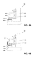
- a grinding machine 40 As a grinding machine for performing wafer backgrinding, as shown in FIG. 6A , a grinding machine 40 is known that is provided with a column 41 , a spindle 43 supported to the column 41 via a ball screw 42 in a cantilever-like manner, and a grindstone 44 attached to a lower end of the spindle 43 , wherein the spindle 43 is lowered by the ball screw 42 while the spindle 43 is being rotated, and a wafer W placed on a chuck 45 is ground by the grindstone 44 (for example, Japanese Patent Application Laid-Open No. 2003-007661).
- an attitude of the spindle 43 can incline due to a reaction force during grinding, so that there is a possibility that the wafer W cannot be processed into a desired shape or a so-called twill line is formed on the backside of the wafer W, which results in damage to the wafer W.
- Patent Literature 1 a semiconductor substrate grinding machine is disclosed that is provided with a guide for sliding a grinding mechanism holding a grinding member in a horizontal direction, a constant-speed moving mechanism for moving the grinding mechanism to a semiconductor substrate at a constant speed to grind the semiconductor substrate, and a constant-pressure moving mechanism for moving the grinding mechanism to the semiconductor substrate such that the semiconductor substrate and the grinding mechanism are pressed with a constant pressure after grinding performed by the constant-speed moving mechanism.
- Patent Literature 2 a grinding machine is disclosed, wherein a grinding wheel is so provided as to be slidable in a vertical direction via a linear guide, and the grinding wheel lowers according to a desired grinding quantity to perform infeed grinding of the backside of a wafer.
- Patent Literature 1 Japanese Patent Application Laid-Open No. 2009-272323
- Patent Literature 2 Japanese Patent No. 5582916
- Patent Literature 2 when processing is performed while the grindstone is being fed at a constant speed, if the grindstone continues giving cutting despite sequential changes of sharpness of abrasive grain tips, the individual abrasive grains may give a wafer cutting equal to or more than a limit above which a crack occurs. As a result, there is a possibility that a fine chip, a crack or the like may be generated in a wafer surface by actual abrasive grain tips.
- the whole grindstone when cutting is given to the wafer, the whole grindstone must be fed carefully such that one abrasive grain does not give a cut equal to or more than a predetermined breaking limit, while keeping the attitude of the grindstone stable and also taking into consideration the sharpness and/or degree of concentration of the abrasive grains.
- a first aspect of the present invention provides a grinding machine including: a rotatable spindle having a lower end to which a grindstone for grinding a wafer is attached; at least two linear guides extending in a vertical direction for slidably supporting the spindle to a column, the linear guides being arranged around an outer periphery of the spindle such that a processing point at which the grindstone grinds the wafer is included therebeween; and a spindle feeding mechanism feeding the spindle downward in the vertical direction, the grinding machine processing the wafer with the grindstone while feeding the spindle in the vertical direction, wherein constant-pressure cylinders are provided, the constant-pressure cylinders being interposed between the spindle feeding mechanism and the column, suspending the spindle and the spindle feeding mechanism, driving pressure being set to be equal to or less than a value corresponding to friction force acting on the grindstone when the spindle feeding mechanism causes the grindstone to cut into the wafer so
- the constant-pressure mechanism raises the spindle and the spindle feeding mechanism temporarily so that the ductile mode grinding is performed in a so-called spindle floating state where the grindstone and the wafer does not excessively contact each other, stable grinding can be performed without damaging the wafer.
- the grindstone since the grindstone is fed in the vertical direction, the grindstone and the spindle lower along a gravity direction to apply a force to the wafer. Even when the sharpness of the tip of the grindstone is changed, the wafer is pressed with a constant pressure, so that the grindstone cuts the wafer according to its sharpness. Thereby, as compared with a conventional configuration feeding a grindstone at a constant-speed, the grindstone cuts the wafer while being fed with a predetermined pressure according the sharpness of the grindstone, stable cutting is given, and occurrence of a crack can be suppressed. In addition, since the grindstone is fed automatically according to a speed at which an actual wafer is ground by processing, constant cutting-in process can also be continued stably during the processing.
- the at least two linear guides are so arranged as to interpose the processing point therebetween, even when a reaction force due to the processing is applied to the grindstone, the grindstone is not inclined by the reaction force, but only pushed back upward in the vertical direction, so that the attitude of the grindstone is always parallel to the wafer, and the grindstone can be kept horizontal. Thereby, the grindstone can continue giving a constant cut while it is excessive processing stress is being suppressed at a portion of the grindstone.
- a second aspect of the present invention provides a grinding machine, the grinding machine wherein in addition to the configuration of the first aspect of the present invention, the constant-pressure cylinders are provided so as to interpose the spindle feeding mechanism therebetween at both sides of the spindle feeding mechanism in a horizontal direction perpendicular to the vertical direction, respectively.
- a third aspect of the present invention provides a grinding machine, wherein in addition to the configuration of the first or second aspects of the present invention, a feeding direction in which the spindle feeding mechanism feeds the spindle is arranged on straight line passing the vertical direction through the processing point at which the grindstone grinds the wafer.
- the spindle feeding mechanism feeds the spindle so as to suppress a reaction force occurring when the grindstone contacts the wafer, so that the ductile mode grinding can be performed stably in the floating state of the spindle.
- a fourth aspect of the present invention provides a grinding machine, wherein in addition to the configuration of any one of the first to third aspects of the present invention, as the at least two linear guides, at least three linear guides are provided, and a gravity of the spindle is arranged within a polygon formed by the linear guides in a plan view.
- the linear guides arranged around the spindle restricts the attitude of the spindle so that the spindle is restrained from yawing, chipping, or rolling to the grinding machine and therefore the ductile mode grinding can be performed stably in the floating state of the spindle.
- the constant-pressure feeding mechanism raises the spindle and the spindle feeding mechanism temporarily, the wafer is ground in the ductile mode in the floating state of the spindle, so that grinding can be performed stably without damaging the wafer.
- a constant pressure is always applied to a wafer surface according the sharpness of the abrasive grain tips, so that it becomes possible to perform grinding in the ductile mode while a constant cutting-in depth is being maintained and while a cutting quantity which does not cause a fatal problem to the wafer like crack occurrence is being maintained.
- FIG. 1 is a perspective view showing a grinding machine according to an embodiment of the present invention
- FIG. 2 is a plan view of a main unit shown in FIG. 1 ;
- FIG. 3 is a side view of the main unit shown in FIG. 1 ;
- FIG. 4 is a perspective view showing an upper portion the main unit
- FIG. 5 is an illustrative view showing an aspect of ductile mode grinding
- FIGS. 6A and 6B are illustrative views showing a conventional grinding machine, FIG. 6A being a view showing an aspect before grinding, and FIG. 6B being a view showing an aspect during grinding; and
- FIG. 7 is an illustrative view showing an aspect of a fragile mode grinding.
- a grinding machine including: a rotatable spindle having a lower end to which a grindstone for grinding a wafer is attached: at least two linear guides extending in a vertical direction for slidably supporting the spindle to a column, the linear guides being arranged around an outer periphery of the spindle such that a processing point at which the grindstone grinds the wafer is included therebeween; and a spindle feeding mechanism feeding the spindle downward in the vertical direction, the grinding machine processing the wafer with the grindstone while feeding the spindle in the vertical direction, wherein constant-pressure cylinders are provided, the constant-pressure cylinders being interposed between the spindle feeding mechanism and the column, and suspending the spindle and the spindle feeding mechanism, driving pressure being set to be equal to or less than a value corresponding to friction force acting on the grindstone when the spindle feeding mechanism causes the grindstone to cut into the wa
- any specific embodiment of the grinding machine according to the present invention can be adopted as long as it grinds a wafer in a ductile mode in a floating state where a spindle does not contact the wafer excessively while the grindstone is being preventing from cutting into the wafer beyond the cutting-in quantity equal to or more than a critical cutting-in depth of the wafer.
- a grinding machine 1 according to an embodiment of the present invention will be described below. It should be noted that when the number of components, a numerical value, a quantity, a range, and the like are referred to a in the following embodiment, the number is not limited to a specific number, unless otherwise specified or unless the principle clearly limited them to the specific number, but may be equal to or more than or less than the specific number.
- shapes of the components and the like or positional relation between the components include substantially approximating or similar shapes or the like, unless otherwise specified or unless the principle clearly deny.
- drawings may be exaggerated by enlarging a feature portions in order to facilitate understanding of features, and size ratios of components or the like may not be actual size ratios. Further, in sectional views, hatching of some components may be omitted in order to facilitate understanding of sectional structures of the component.
- FIG. 1 is a perspective view showing a basic configuration of a grinding machine 1 where a constant-pressure feeding mechanism is omitted.
- FIG. 2 is a plan view of a main unit 2 shown in FIG. 1 .
- FIG. 3 is a side view of the main unit 2 .
- FIG. 4 is a perspective view showing an upper portion of the main unit 2 .
- the grinding machine 1 performs backgrinding of a wafer W into a thin film.
- the wafer W subjected to grinding process using the grinding machine 1 is preferably one showing high hardness and/or high fragility such as silicon wafer, silicon carbide wafer or the like, but the wafer W is not limited to these wafers.
- the grinding machine 1 is provided with the main unit 2 provided with a grindstone 21 , and a conveying unit 3 arranged below the main unit 2 .
- the main unit 2 is provided with a arch-like column 22 , a spindle 23 attached to the grindstone 21 , three linear guides 24 supporting the spindle 23 slidably in a vertical direction V, and a spindle feeding mechanism 25 moving the spindle 23 upward and downward in the vertical direction V.
- the conveying unit 3 is provided with a chuck 31 capable of sucking and holding the wafer W, and a slider 32 on which the chuck 31 is placed.
- the chuck 31 is connected to a vacuum source (not shown) and is capable of vacuum-sucking the wafer W to a surface of the chuck 31 . Further, the chuck 31 can be rotated about a vertical axis passing through the center of the chuck 31 by a motor (not shown).
- the slider 32 can be slid on a rail 33 by a slider driving mechanism (not shown), so that the chuck 31 and slide 32 are slid in a wafer conveying direction D 1 in an integral manner.
- the wafer W which has been vacuum-sucked on the chuck 31 is conveyed up to below the grindstone 21 by the slider 32 before the grinding processing, and it is conveyed from below the grindstone 21 to behind the main unit 2 after the grinding processing.
- the operation of the grinding machine 1 is controlled by a control unit (not shown).
- the control unit is for controlling components constituting the grinding machine 1 , respectively.
- the control unit is composed of a CPU, a memory or the like, for example. It should be noted that the function of the control unit may be realized by performing control using a software, or it may be realized by conducting an action using a hardware.
- the spindle 23 is received in a groove 22 b provided in a front face 22 a of the column 22 in a recessed manner and extending in the vertical direction V.
- the spindle 23 is provided with a saddle 23 a having the grindstone 21 attached to its lower end, and a motor 23 b provided within the saddle 23 a to rotate the grindstone 21 .
- the linear guide 24 is composed of two front linear guides 24 a arranged on the front of the column 22 , and one rear linear guide 24 b arranged in the groove 22 b .
- the front linear guides 24 a and the rear linear guide 24 b are provided in parallel to one another along the vertical direction V.
- the saddle 23 a is directly attached to the front linear guides 24 a . Further, the saddle 23 a is attached to the rear linear guide 24 b via a nut 25 a described later. Thereby, the front linear guides 24 a and the rear linear guide 24 b function as guide rails for the saddle 23 a.
- the front linear guides 24 a are arranged at edge portions of the groove 22 b .
- the rear linear guide 24 b is arranged on a bottom portion of the groove 22 b .
- the front linear guides 24 a and the rear linear guide 24 b are arranged apart from one another such that gravity G of the spindle 23 is arranged within a triangle T formed by the front linear guides 24 a and the rear linear guide 24 b in a plan view.
- the spindle feeding mechanism 25 is provided with a nut 25 a coupling the saddle 23 a and the rear linear guide 24 b to each other, a ball screw 25 b moving the nut 25 a upward and downward, and a motor 25 c for rotating the ball screw 25 b .
- the motor 25 c is driven to rotate the ball screw 25 b forward, the nut 25 a is lowered in a feeding direction D 2 of the ball screw 25 b parallel to the vertical direction V, so that the saddle 23 a is lowered.
- the feeding direction D 2 is on a straight line parallel to the vertical direction V and passing through a processing point P at which the grindstone 21 processes the wafer W.
- a rotation axis O of the ball screw 25 b and the processing point P of the grindstone 21 are arranged on the same straight line in the vertical direction V.
- the spindle 23 and the spindle feeding mechanism 25 are coupled to a counterweight (not shown), and they are suspended by a constant-pressure cylinders 26 described later in a balanced state with the counterweight. Thereby, the spindle feeding mechanism 25 can lower the spindle 23 to a grinding start position at a high speed. Further, the grindstone 21 is caused to cut into the wafer W by a quantity corresponding to the spindle 23 fed by the spindle feeding mechanism 25 , and a feeding quantity of the spindle feeding mechanism 25 can be known accurately according to a rotation quantity of the ball screw 25 b , so that a grinding quantity can be controlled precisely.
- the main unit 2 is provided with an in-process gauge (not shown) for measuring the thickness of the wafer W.
- an in-process gauge (not shown) for measuring the thickness of the wafer W.
- the main unit 2 is provided with the constant-pressure cylinders 26 as a floating mechanism.
- the constant-pressure cylinders 26 are provided so as to interpose the nuts 25 a of the spindle feeding mechanism 25 therebeween at both sides one by one in a horizontal direction H, and they are interposed between the column 22 and the nuts 25 a .
- the constant-pressure cylinder 26 is an air cylinder adopting a known configuration composed of a cylinder, a piston, a piston rod, a compressor and the like (not shown).
- a driving pressure of the constant-pressure cylinder 26 is set to be equal to or less than a value corresponding to a friction force acting on the grindstone 21 when the grindstone 21 cuts into the wafer W by the critical cutting-in depth (Dc value).
- the Dc value varies according to materials of the wafer W, and, for example, is 0.09 ⁇ m for a silicon wafer and is 0.15 ⁇ m for a silicon carbide wafer.
- the constant-pressure cylinder 26 suspends the spindle 23 and the spindle feeding mechanism 25 within the groove 22 b .
- a lower end of the piston rod of the constant-pressure cylinder 26 are coupled to the nuts 25 a , and when a friction force acting on the grindstone 21 is transmitted to the piston rod during the grinding processing, the piston is raised so as to press back compressed air filling in the cylinder of the constant-pressure cylinder 26 . Therefore, when the friction force acting on the grindstone 21 is excessively increased by the grindstone 21 trying to cut deeper than a desired grinding quantity (for example, DC value), the spindle 23 and the spindle feeding mechanism 25 are temporarily raised. Thereby, it is suppressed that cutting by the grindstone 21 is equal to or more than the DC value.
- a desired grinding quantity for example, DC value
- the constant-pressure cylinder 26 temporarily raises the spindle 23 and the spindle feeding mechanism 25 , so that damage of the wafer W can be suppressed.
- the constant-pressure cylinder 26 does not press the spindle 23 downward in the vertical direction, and feeding (infeed) of the spindle 23 is performed only by the spindle feeding mechanism 25 .
- the grindstone 21 is caused to cut into the wafer W by the feeding quantity of the spindle feeding mechanism 25 and the feeding quantity of the spindle feeding mechanism 25 can be known accurately from the rotation quantity of the ball screw 25 b , so that the feeding quantity of the grindstone 21 can be controlled precisely.
- the spindle feeding mechanism 25 causes the grindstone 21 to cut into the wafer W and friction force equal to or more than the driving pressure of the constant-pressure cylinder 26 acts on the grindstone 21 , the constant-pressure cylinder 26 raises the spindle 23 and the spindle feeding mechanism 25 .
- the constant-pressure cylinders 26 are provided at both side of the spindle feeding mechanism 25 in the horizontal direction H so as interpose the spindle feeding mechanism 25 therebetween, the spindle feeding mechanism 25 is prevented from being inclined in the horizontal direction H when the spindle feeding mechanism 25 is raised. Therefore, as shown in FIG. 5 , the wafer W can be ground in the ductile mode in a so-called floating state where an abrasive grain of the grindstone 21 does not excessively contact the wafer W during the grinding processing.
- setting may be such that a grindstone 21 of #8000 is prepared, a rotation speed of the spindle 23 is 2000 rpm, a rotation speed of the chuck 31 is 300 rpm, a load during grinding is 20 kg, and a feeding speed of the spindle feeding mechanism 25 is 0.4 ⁇ m/s.
- the SiC substrate can be ground in the ductile mode.
- the term “load during grinding” corresponds to a driving pressure (500 kPa) of the constant-pressure cylinder 26 set when the grindstone 21 is separated from the wafer W by 1 ⁇ m.
- the spindle feeding mechanism 25 is restrained from moving in the horizontal direction H, so that the ductile mode grinding can be further stably performed in the floating state of the spindle 23 .
- the spindle feeding mechanism 25 feeds the spindle 23 so as to suppress reaction force occurring when the grindstone 23 contacts the wafer W, so that the ductile mode grinding can be further stably performed in the floating state of the spindle 23 .
- grinding since grinding is performed while the spindle 23 pressing the wafer only by its own weight along the vertical direction V, grinding can be performed with fine reduced sliding resistance and at slight cutting-in depth as compared with a conventional grinding machine feeding a grindstone in a horizontal direction to perform grinding.
- the linear guides 24 arranged around the spindle 23 restricts the attitude of the spindle 23 , so that the ductile mode grinding can be stably performed in the floating state.
- the specific configuration of the floating mechanism is not limited to the above-described one, but any configuration can be adopted as long as the spindle can be so raised as to release excessive friction force acting on the grindstone.
- any specific configuration of the linear guide may be adopted as long as it is capable of restricting raising and lowering of the spindle to the vertical direction, and it is not limited to the such a configuration as described above in which the spindle is supported such that the gravity of the spindle is arranged within the polygon formed by the linear guides in a plan view, but it may be for example a configuration where the spindle is supported by two linear guides and the gravity of the spindle is arranged on a straight line formed by the two linear guides in a plan view.
Landscapes
- Engineering & Computer Science (AREA)
- Mechanical Engineering (AREA)
- Grinding Of Cylindrical And Plane Surfaces (AREA)
- Mechanical Treatment Of Semiconductor (AREA)
- Constituent Portions Of Griding Lathes, Driving, Sensing And Control (AREA)
Applications Claiming Priority (5)
| Application Number | Priority Date | Filing Date | Title |
|---|---|---|---|
| JP2015-194484 | 2015-09-30 | ||
| JP2015194484 | 2015-09-30 | ||
| JP2016131107 | 2016-06-30 | ||
| JP2016-131107 | 2016-06-30 | ||
| PCT/JP2016/078782 WO2017057548A1 (ja) | 2015-09-30 | 2016-09-29 | 研削盤 |
Publications (2)
| Publication Number | Publication Date |
|---|---|
| US20180229341A1 US20180229341A1 (en) | 2018-08-16 |
| US10173296B2 true US10173296B2 (en) | 2019-01-08 |
Family
ID=58423763
Family Applications (1)
| Application Number | Title | Priority Date | Filing Date |
|---|---|---|---|
| US15/751,421 Active US10173296B2 (en) | 2015-09-30 | 2016-09-29 | Grinding machine |
Country Status (3)
| Country | Link |
|---|---|
| US (1) | US10173296B2 (ja) |
| JP (1) | JP6335397B2 (ja) |
| WO (1) | WO2017057548A1 (ja) |
Cited By (2)
| Publication number | Priority date | Publication date | Assignee | Title |
|---|---|---|---|---|
| US20190210178A1 (en) * | 2016-09-28 | 2019-07-11 | Tokyo Seimitsu Co., Ltd. | Processing device and method for setting processing device |
| US10421172B2 (en) * | 2015-12-01 | 2019-09-24 | Tokyo Seimitsu Co. Ltd. | Processing device |
Families Citing this family (4)
| Publication number | Priority date | Publication date | Assignee | Title |
|---|---|---|---|---|
| JP2019155488A (ja) * | 2018-03-07 | 2019-09-19 | 株式会社東京精密 | 研削盤 |
| CN111157317B (zh) * | 2020-01-23 | 2024-01-05 | 北京市理化分析测试中心 | 一种高分子材料老化试验粉体制备装置及具有该粉体制备装置的老化试验箱 |
| CN113664715B (zh) * | 2021-08-30 | 2024-09-27 | 兰州兰石能源装备工程研究院有限公司 | 磁性研磨机生产线驱动进给装置 |
| CN118832514A (zh) * | 2024-07-12 | 2024-10-25 | 上海创元化妆品有限公司 | 一种硬质材料的等径深孔抛光设备 |
Citations (15)
| Publication number | Priority date | Publication date | Assignee | Title |
|---|---|---|---|---|
| US3988965A (en) * | 1971-12-16 | 1976-11-02 | Giddings & Lewis, Inc. | Two pressure counterbalance system for machine tool headstocks |
| US4616447A (en) * | 1983-02-26 | 1986-10-14 | Mafell-Saschinenfabrik Rudolf Mey GmbH & Co. KG | Method and apparatus for machining a workpiece ultrasonically |
| US5123789A (en) * | 1989-02-28 | 1992-06-23 | Hitachi Seiko, Ltd. | Method of and apparatus for machining printed circuit board |
| JP2001191237A (ja) | 1999-12-28 | 2001-07-17 | Nichia Chem Ind Ltd | 研削盤 |
| JP2003007661A (ja) | 1999-01-06 | 2003-01-10 | Tokyo Seimitsu Co Ltd | 平面加工装置及び平面加工方法 |
| JP2003071710A (ja) | 2001-08-28 | 2003-03-12 | Nagase Integrex Co Ltd | 研削盤 |
| JP2004322215A (ja) | 2003-04-21 | 2004-11-18 | M Tec Kk | ワーク表面の研摩方法及び装置 |
| US6910946B2 (en) * | 2002-03-23 | 2005-06-28 | Fineacetechnology Co., Ltd. | Polishing machine |
| JP2007210074A (ja) | 2006-02-10 | 2007-08-23 | Shuwa Kogyo Kk | 研削装置および研磨装置、並びに研削方法および研磨方法 |
| JP2009272323A (ja) | 2008-04-30 | 2009-11-19 | Hitachi Cable Ltd | 半導体基板研削機及び研削方法 |
| JP2012040620A (ja) | 2010-08-13 | 2012-03-01 | Tokyo Seimitsu Co Ltd | 研削盤 |
| JP2012223863A (ja) | 2011-04-21 | 2012-11-15 | Disco Corp | 表面に金属膜が被覆された硬質基板の研削方法 |
| JP2013128070A (ja) | 2011-12-19 | 2013-06-27 | Tokyo Seimitsu Co Ltd | ウェーハ研削方法およびウェーハ研削装置 |
| US20130316619A1 (en) * | 2011-02-09 | 2013-11-28 | Bernhard And Company Ltd | Reel mower grinder with auto- index mechanism |
| JP2015054373A (ja) | 2013-09-12 | 2015-03-23 | 株式会社ディスコ | 加工装置 |
-
2016
- 2016-09-29 JP JP2017543543A patent/JP6335397B2/ja active Active
- 2016-09-29 WO PCT/JP2016/078782 patent/WO2017057548A1/ja not_active Ceased
- 2016-09-29 US US15/751,421 patent/US10173296B2/en active Active
Patent Citations (15)
| Publication number | Priority date | Publication date | Assignee | Title |
|---|---|---|---|---|
| US3988965A (en) * | 1971-12-16 | 1976-11-02 | Giddings & Lewis, Inc. | Two pressure counterbalance system for machine tool headstocks |
| US4616447A (en) * | 1983-02-26 | 1986-10-14 | Mafell-Saschinenfabrik Rudolf Mey GmbH & Co. KG | Method and apparatus for machining a workpiece ultrasonically |
| US5123789A (en) * | 1989-02-28 | 1992-06-23 | Hitachi Seiko, Ltd. | Method of and apparatus for machining printed circuit board |
| JP2003007661A (ja) | 1999-01-06 | 2003-01-10 | Tokyo Seimitsu Co Ltd | 平面加工装置及び平面加工方法 |
| JP2001191237A (ja) | 1999-12-28 | 2001-07-17 | Nichia Chem Ind Ltd | 研削盤 |
| JP2003071710A (ja) | 2001-08-28 | 2003-03-12 | Nagase Integrex Co Ltd | 研削盤 |
| US6910946B2 (en) * | 2002-03-23 | 2005-06-28 | Fineacetechnology Co., Ltd. | Polishing machine |
| JP2004322215A (ja) | 2003-04-21 | 2004-11-18 | M Tec Kk | ワーク表面の研摩方法及び装置 |
| JP2007210074A (ja) | 2006-02-10 | 2007-08-23 | Shuwa Kogyo Kk | 研削装置および研磨装置、並びに研削方法および研磨方法 |
| JP2009272323A (ja) | 2008-04-30 | 2009-11-19 | Hitachi Cable Ltd | 半導体基板研削機及び研削方法 |
| JP2012040620A (ja) | 2010-08-13 | 2012-03-01 | Tokyo Seimitsu Co Ltd | 研削盤 |
| US20130316619A1 (en) * | 2011-02-09 | 2013-11-28 | Bernhard And Company Ltd | Reel mower grinder with auto- index mechanism |
| JP2012223863A (ja) | 2011-04-21 | 2012-11-15 | Disco Corp | 表面に金属膜が被覆された硬質基板の研削方法 |
| JP2013128070A (ja) | 2011-12-19 | 2013-06-27 | Tokyo Seimitsu Co Ltd | ウェーハ研削方法およびウェーハ研削装置 |
| JP2015054373A (ja) | 2013-09-12 | 2015-03-23 | 株式会社ディスコ | 加工装置 |
Cited By (3)
| Publication number | Priority date | Publication date | Assignee | Title |
|---|---|---|---|---|
| US10421172B2 (en) * | 2015-12-01 | 2019-09-24 | Tokyo Seimitsu Co. Ltd. | Processing device |
| US20190210178A1 (en) * | 2016-09-28 | 2019-07-11 | Tokyo Seimitsu Co., Ltd. | Processing device and method for setting processing device |
| US11141830B2 (en) * | 2016-09-28 | 2021-10-12 | Tokyo Seimitsu Co., Ltd | Method for setting processing device |
Also Published As
| Publication number | Publication date |
|---|---|
| JP6335397B2 (ja) | 2018-06-06 |
| JPWO2017057548A1 (ja) | 2018-02-22 |
| WO2017057548A1 (ja) | 2017-04-06 |
| US20180229341A1 (en) | 2018-08-16 |
Similar Documents
| Publication | Publication Date | Title |
|---|---|---|
| US10173296B2 (en) | Grinding machine | |
| JP6030265B1 (ja) | 研削盤 | |
| US7867059B2 (en) | Semiconductor wafer, apparatus and process for producing the semiconductor wafer | |
| JP7460711B2 (ja) | 加工装置 | |
| US12138743B2 (en) | Polishing device | |
| US11141830B2 (en) | Method for setting processing device | |
| CN103282173A (zh) | 柱状部件的加工装置 | |
| JP2019155488A (ja) | 研削盤 | |
| JP4878738B2 (ja) | 半導体デバイスの加工方法 | |
| JP2016013615A (ja) | 仕上研削装置および仕上研削方法 | |
| JP7128635B2 (ja) | 研削盤 | |
| JP2006332281A (ja) | 半導体ウェーハの製造方法および両面研削方法並びに半導体ウェーハの両面研削装置 | |
| JP2012222123A (ja) | 半導体ウェハの研削方法 | |
| KR101303552B1 (ko) | 반도체 웨이퍼의 양면을 화학적으로 그라인딩하는 방법 | |
| JP4833629B2 (ja) | ウエーハの加工方法および研削装置 | |
| JP5384193B2 (ja) | 被加工物の保持ユニット | |
| JP2021137900A (ja) | 加工装置 | |
| US20230302603A1 (en) | Processing device | |
| KR102914220B1 (ko) | 웨이퍼의 연삭 방법 | |
| JP2018039085A (ja) | 切削方法 | |
| CN117400079A (zh) | 晶片的磨削方法和磨削装置 | |
| JP2015006709A (ja) | ウエーハの研削方法及び研削装置 | |
| JP7703064B2 (ja) | 加工装置 | |
| KR20240011620A (ko) | 피가공물의 연삭 방법 |
Legal Events
| Date | Code | Title | Description |
|---|---|---|---|
| AS | Assignment |
Owner name: TOKYO SEIMITSU CO., LTD, JAPAN Free format text: ASSIGNMENT OF ASSIGNORS INTEREST;ASSIGNORS:KANAZAWA, MASAKI;IGARASHI, KENJI;SIGNING DATES FROM 20171213 TO 20171215;REEL/FRAME:044875/0213 |
|
| FEPP | Fee payment procedure |
Free format text: ENTITY STATUS SET TO UNDISCOUNTED (ORIGINAL EVENT CODE: BIG.); ENTITY STATUS OF PATENT OWNER: LARGE ENTITY |
|
| STCF | Information on status: patent grant |
Free format text: PATENTED CASE |
|
| MAFP | Maintenance fee payment |
Free format text: PAYMENT OF MAINTENANCE FEE, 4TH YEAR, LARGE ENTITY (ORIGINAL EVENT CODE: M1551); ENTITY STATUS OF PATENT OWNER: LARGE ENTITY Year of fee payment: 4 |