WO2017056940A1 - 燃料噴射装置 - Google Patents
燃料噴射装置 Download PDFInfo
- Publication number
- WO2017056940A1 WO2017056940A1 PCT/JP2016/076789 JP2016076789W WO2017056940A1 WO 2017056940 A1 WO2017056940 A1 WO 2017056940A1 JP 2016076789 W JP2016076789 W JP 2016076789W WO 2017056940 A1 WO2017056940 A1 WO 2017056940A1
- Authority
- WO
- WIPO (PCT)
- Prior art keywords
- yoke
- valve seat
- tube portion
- fuel
- cylinder
- Prior art date
- Legal status (The legal status is an assumption and is not a legal conclusion. Google has not performed a legal analysis and makes no representation as to the accuracy of the status listed.)
- Ceased
Links
Images


Classifications
-
- F—MECHANICAL ENGINEERING; LIGHTING; HEATING; WEAPONS; BLASTING
- F02—COMBUSTION ENGINES; HOT-GAS OR COMBUSTION-PRODUCT ENGINE PLANTS
- F02M—SUPPLYING COMBUSTION ENGINES IN GENERAL WITH COMBUSTIBLE MIXTURES OR CONSTITUENTS THEREOF
- F02M51/00—Fuel-injection apparatus characterised by being operated electrically
- F02M51/06—Injectors peculiar thereto with means directly operating the valve needle
- F02M51/061—Injectors peculiar thereto with means directly operating the valve needle using electromagnetic operating means
- F02M51/0625—Injectors peculiar thereto with means directly operating the valve needle using electromagnetic operating means characterised by arrangement of mobile armatures
- F02M51/0664—Injectors peculiar thereto with means directly operating the valve needle using electromagnetic operating means characterised by arrangement of mobile armatures having a cylindrically or partly cylindrically shaped armature, e.g. entering the winding; having a plate-shaped or undulated armature entering the winding
- F02M51/0671—Injectors peculiar thereto with means directly operating the valve needle using electromagnetic operating means characterised by arrangement of mobile armatures having a cylindrically or partly cylindrically shaped armature, e.g. entering the winding; having a plate-shaped or undulated armature entering the winding the armature having an elongated valve body attached thereto
-
- F—MECHANICAL ENGINEERING; LIGHTING; HEATING; WEAPONS; BLASTING
- F02—COMBUSTION ENGINES; HOT-GAS OR COMBUSTION-PRODUCT ENGINE PLANTS
- F02M—SUPPLYING COMBUSTION ENGINES IN GENERAL WITH COMBUSTIBLE MIXTURES OR CONSTITUENTS THEREOF
- F02M51/00—Fuel-injection apparatus characterised by being operated electrically
- F02M51/06—Injectors peculiar thereto with means directly operating the valve needle
- F02M51/061—Injectors peculiar thereto with means directly operating the valve needle using electromagnetic operating means
- F02M51/0614—Injectors peculiar thereto with means directly operating the valve needle using electromagnetic operating means characterised by arrangement of electromagnets or fixed armature
-
- F—MECHANICAL ENGINEERING; LIGHTING; HEATING; WEAPONS; BLASTING
- F02—COMBUSTION ENGINES; HOT-GAS OR COMBUSTION-PRODUCT ENGINE PLANTS
- F02M—SUPPLYING COMBUSTION ENGINES IN GENERAL WITH COMBUSTIBLE MIXTURES OR CONSTITUENTS THEREOF
- F02M55/00—Fuel-injection apparatus characterised by their fuel conduits or their venting means; Arrangements of conduits between fuel tank and pump F02M37/00
- F02M55/004—Joints; Sealings
- F02M55/005—Joints; Sealings for high pressure conduits, e.g. connected to pump outlet or to injector inlet
-
- F—MECHANICAL ENGINEERING; LIGHTING; HEATING; WEAPONS; BLASTING
- F02—COMBUSTION ENGINES; HOT-GAS OR COMBUSTION-PRODUCT ENGINE PLANTS
- F02M—SUPPLYING COMBUSTION ENGINES IN GENERAL WITH COMBUSTIBLE MIXTURES OR CONSTITUENTS THEREOF
- F02M51/00—Fuel-injection apparatus characterised by being operated electrically
- F02M51/005—Arrangement of electrical wires and connections, e.g. wire harness, sockets, plugs; Arrangement of electronic control circuits in or on fuel injection apparatus
Definitions
- the present disclosure relates to a fuel injection device that injects and supplies fuel to an internal combustion engine.
- a nozzle holder that constitutes a part of a housing is press-fitted into a fixed core.
- the fixed core and the nozzle holder are joined by welding at the press-fitting position.
- the nozzle holder is formed with a magnetic throttle part having a thin part, and the magnetic throttle part is press-fitted into the fixed core and joined to the fixed core by welding.
- the fixed core and the nozzle holder are arranged in the axial direction at the welded portion between the fixed core and the nozzle holder or at the thin magnetic throttle portion. A force in the direction of leaving acts. If the pressure of the fuel in the fuel passage in the apparatus is excessive, stress concentrates on the welded portion or the magnetic throttle part between the fixed core and the nozzle holder, and the welded part or the magnetic throttle part may be broken. If the welded part or the magnetic restrictor is broken, the fuel in the fuel passage may leak to the outside. Therefore, in the fuel injection device of Patent Document 1, it is difficult to inject high-pressure fuel due to the structure.
- This disclosure is intended to provide a fuel injection device capable of injecting high-pressure fuel with high accuracy while suppressing fuel leakage.
- the fuel injection device of the present disclosure includes a nozzle, a housing, a needle, a movable core, a fixed core, a valve seat side urging member, a yoke, and a coil.
- the nozzle has an injection hole through which fuel is injected and a valve seat formed in an annular shape around the injection hole.
- the housing has a first cylinder part whose one end is connected to the nozzle, a second cylinder part whose one end is connected to the other end of the first cylinder part and forms a magnetic throttle part in at least a part in the axial direction, and one end which is the second cylinder.
- a third cylinder connected to the other end of the nozzle, and a fuel passage that is formed inside the first cylinder, the second cylinder, and the third cylinder so as to communicate with the nozzle hole and guides fuel to the nozzle hole. is doing.
- the needle has a rod-shaped needle body and a seal portion formed in an annular shape at one end of the needle body so as to be in contact with the valve seat, and when the seal portion is separated from the valve seat or comes into contact with the valve seat, the nozzle hole Open and close.
- the movable core is provided so as to reciprocate in the housing together with the needle.
- the fixed core is provided on the side opposite to the valve seat with respect to the movable core inside the second cylinder part and the third cylinder part.
- the valve seat side biasing member can bias the needle and the movable core toward the valve seat.
- the yoke is formed in a cylindrical shape, one end side is connected to the first tube portion, the other end side is connected to the third tube portion, and the first tube portion and the third tube portion are connected to the first tube portion and the third tube portion.
- the coil is provided between the housing and the yoke.
- a magnetic circuit is formed in the first cylindrical portion, the movable core, the fixed core, the third cylindrical portion, and the yoke, and the movable core is attracted to the fixed core side. It is possible to move the needle away from the valve seat.
- the yoke is provided in the first tube portion and the third tube portion so as to generate an axial force in a direction in which the first tube portion and the third tube portion approach each other. Therefore, a force in a direction contracting in the axial direction from the first and third cylindrical portions acts on the second cylindrical portion forming the magnetic aperture portion.
- the connection portion between the second tube portion and the first tube portion, the connection portion between the second tube portion and the third tube portion, or the magnetic throttle portion can be suppressed.
- the force in the direction of contracting in the axial direction from the first cylinder part and the third cylinder part acts on the second cylinder part forming the magnetic throttle part, the pressure of the fuel in the fuel passage Even if the height increases, it is possible to suppress the position of the magnetic aperture portion relative to the fixed core from shifting in the axial direction. Therefore, it can suppress that the magnitude
- the fuel injection device can inject high-pressure fuel with high accuracy while suppressing fuel leakage.
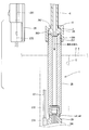
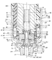
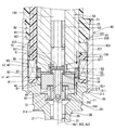
- FIG. 1 is a cross-sectional view illustrating a fuel injection device according to a first embodiment of the present disclosure.
- FIG. 2 is a cross-sectional view showing a fuel inlet portion and its vicinity of the fuel injection device according to the first embodiment of the present disclosure.
- FIG. 3 is a cross-sectional view showing a yoke and its vicinity of the fuel injection device according to the first embodiment of the present disclosure.
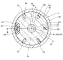
- 4 is a cross-sectional view taken along line IV-IV in FIG.
- FIG. 5 is a cross-sectional view showing a third tubular portion protruding portion and its vicinity of a fuel injection device according to a second embodiment of the present disclosure.
- FIG. 6 is a cross-sectional view showing a third tubular portion protruding portion and its vicinity of a fuel injection device according to a third embodiment of the present disclosure.
- FIG. 7 is a cross-sectional view illustrating a yoke and its vicinity of a fuel injection device according to a fourth embodiment of the present disclosure.
- FIG. 8 is a cross-sectional view illustrating a yoke and its vicinity of a fuel injection device according to a fifth embodiment of the present disclosure.
- FIG. 9 is a cross-sectional view showing a yoke and its vicinity of a fuel injection device according to a sixth embodiment of the present disclosure.
- FIG. 6 is a cross-sectional view showing a third tubular portion protruding portion and its vicinity of a fuel injection device according to a third embodiment of the present disclosure.
- FIG. 7 is a cross-sectional view illustrating a yoke and its vicinity of a fuel injection device according to a fourth embodiment of the present disclosure.
- FIG. 10 is a cross-sectional view showing a yoke and its vicinity of a fuel injection device according to a seventh embodiment of the present disclosure.
- FIG. 11 is a cross-sectional view showing a yoke and its vicinity of a fuel injection device according to an eighth embodiment of the present disclosure.
- FIG. 1 A fuel injection valve according to a first embodiment of the present disclosure is shown in FIG.
- the fuel injection device 1 is used in, for example, a direct injection gasoline engine (hereinafter referred to as “engine”) 2 as an internal combustion engine, and injects and supplies gasoline as fuel to the engine 2.
- engine direct injection gasoline engine
- the fuel injection device 1 includes a nozzle 10, a housing 20, a needle 30, a movable core 40, a fixed core 50, a gap forming member 60, a spring 71 as a valve seat side biasing member, a coil 80, a yoke 90, an inlet portion 24, a filter. 241, a cylindrical member 25, a screw coupling member 26, and the like.
- the nozzle 10 is formed of a material having a relatively high hardness such as martensitic stainless steel.
- the nozzle 10 is subjected to a quenching process so as to have a predetermined hardness.
- the nozzle 10 has a nozzle cylinder part 11 and a nozzle bottom part 12 that closes one end of the nozzle cylinder part 11.
- the nozzle bottom 12 is formed with a plurality of nozzle holes 13 that connect the surface on the nozzle tube portion 11 side and the surface on the opposite side of the nozzle tube portion 11.
- An annular valve seat 14 is formed around the nozzle hole 13 on the surface of the nozzle bottom portion 12 on the nozzle cylinder portion 11 side.
- the housing 20 includes a first cylinder part 21, a second cylinder part 22, a third cylinder part 23, and the like.
- the first cylinder part 21, the second cylinder part 22, and the third cylinder part 23 are all formed in a substantially cylindrical shape.
- the 1st cylinder part 21, the 2nd cylinder part 22, and the 3rd cylinder part 23 are arrange
- the 2nd cylinder part 22, the 1st cylinder part 21, and the 3rd cylinder part 23 are connected by welding, for example.
- a connection portion between the second tube portion 22 and the first tube portion 21 is indicated by c1
- a connection portion between the second tube portion 22 and the third tube portion 23 is indicated by c2.
- connection part c1 a melted part w1 is formed in which a part of the second cylinder part 22 and a part of the first cylinder part 21 are melted and cooled by welding.
- the connecting portion c2 is formed with a melted portion w2 in which a part of the second cylinder part 22 and a part of the third cylinder part 23 are melted and cooled by welding.
- the first cylinder part 21 and the third cylinder part 23 are made of a magnetic material such as ferritic stainless steel and are subjected to magnetic stabilization treatment.
- the 1st cylinder part 21 and the 3rd cylinder part 23 have comparatively low hardness.
- the 2nd cylinder part 22 is formed with nonmagnetic materials, such as austenitic stainless steel, for example. That is, the 2nd cylinder part 22 forms the magnetic aperture part 221 in all the axial directions.
- the hardness of the second cylinder part 22 is higher than the hardness of the first cylinder part 21 and the third cylinder part 23.
- the end of the first tube portion 21 opposite to the second tube portion 22 is joined to the end of the nozzle tube portion 11 opposite to the nozzle bottom 12.
- the 1st cylinder part 21 and the nozzle 10 are connected by welding, for example.
- the connection part of the 1st cylinder part 21 and the nozzle 10 is shown by c3.
- a melted part w3 is formed in which a part of the first cylinder part 21 and a part of the nozzle 10 are melted and cooled and solidified by welding.
- the inlet portion 24 is formed in a cylindrical shape from a metal such as stainless steel.
- the inlet portion 24 is provided so that one end thereof is connected to the radially inner side of the end portion of the third cylinder portion 23 opposite to the second cylinder portion 22.
- the inlet part 24 and the 3rd cylinder part 23 are integrally formed with the same material.
- the boundary between the inlet portion 24 and the third cylindrical portion 23 is indicated by a two-dot chain line.
- the cylindrical member 25 is provided on the opposite side of the inlet portion 24 from the third cylindrical portion 23.
- the cylindrical member 25 is formed in a cylindrical shape from a metal such as stainless steel.
- the cylindrical member 25 is provided so that one end thereof is connected to the radially outer side of the end portion of the inlet portion 24 opposite to the third cylindrical portion 23.
- the cylinder member 25 and the inlet part 24 are connected by welding, for example.
- FIG. 1 the connection part of the cylinder member 25 and the inlet part 24 is shown by c4.
- the connecting portion c4 is formed with a melted portion w4 in which a part of the cylindrical member 25 and a part of the inlet portion 24 are melted and cooled by welding.
- a threaded portion 251 is formed on the outer wall of the end portion of the cylindrical member 25 opposite to the inlet portion 24.
- a fuel pipe 6 through which fuel from the outside flows is connected to an end portion of the cylindrical member 25 opposite to the inlet portion 24.
- a protruding portion 7 is formed that protrudes annularly outward in the radial direction.
- a locking surface 8 is formed on the end surface of the protruding portion 7 opposite to the cylindrical member 25.
- the screw coupling member 26 is formed in a cylindrical shape from a metal such as stainless steel.
- a screw portion 261 that can be screwed into the screw portion 251 is formed on the inner wall of one end portion of the screw coupling member 26.
- a protruding portion 262 that protrudes radially inward is formed at the other end of the screw coupling member 26.
- a locking surface 263 is formed on the end surface of the protruding portion 262 on the screw portion 261 side.
- the screw coupling member 26 is in a state in which the end surface on the opposite side of the inlet portion 24 of the cylinder member 25 and the end surface on the cylinder member 25 side of the fuel pipe 6 are in contact, and the locking surface 263 and the locking surface 8 are in contact
- the screw part 261 is screwed to the screw part 251 so that At this time, the cylindrical member 25 and the fuel pipe 6 are in a state in which an axial force in a direction in which the cylindrical member 25 and the fuel pipe 6 approach each other is applied.
- the end surface of the cylinder member 25 opposite to the inlet portion 24 and the end surface of the fuel pipe 6 on the cylinder member 25 side are brought into close contact with each other.
- a fuel passage 100 is formed inside the housing 20 and the nozzle cylinder 11.
- the fuel passage 100 communicates with the nozzle hole 13. Thereby, fuel from the outside such as a fuel supply source flows into the fuel passage 100 via the fuel pipe 6, the cylindrical member 25, and the inlet portion 24.
- the fuel passage 100 guides fuel to the nozzle hole 13.
- the inlet portion 24 and the cylindrical member 25 correspond to a “fuel inlet portion”.
- the filter 241 is provided inside the inlet portion 24. The filter 241 collects foreign matters in the fuel flowing into the fuel passage 100.
- the needle 30 is formed of a material having a relatively high hardness such as martensitic stainless steel.
- the needle 30 is quenched so as to have a predetermined hardness.
- the hardness of the needle 30 is set substantially equal to the hardness of the nozzle 10.
- the needle 30 is accommodated in the housing 20 so as to reciprocate in the fuel passage 100 in the direction of the axis Ax1 of the housing 20.
- the needle 30 includes a needle body 31, a seal portion 32, a flange portion 33, and the like.
- the needle body 31 is formed in a rod shape, more specifically, a long columnar shape.
- the seal portion 32 is formed at one end of the needle body 31, that is, at the end portion on the valve seat 14 side, and can contact the valve seat 14.
- the collar portion 33 is formed in an annular shape, and is provided on the other end of the needle body 31, that is, on the radially outer side of the end portion opposite to the valve seat 14.
- the flange portion 33 is integrally formed of the same material as the needle body 31.
- a large diameter portion 311 is formed in the vicinity of one end of the needle body 31.
- the outer diameter on one end side of the needle body 31 is smaller than the outer diameter on the other end side.
- the large diameter portion 311 has an outer diameter larger than the outer diameter on one end side of the needle body 31 and is equal to the outer diameter on the other end side of the needle body 31.
- the large diameter portion 311 is formed so that the outer wall slides with the inner wall of the nozzle cylinder portion 11 of the nozzle 10. As a result, the needle 30 is guided to reciprocate in the direction of the axis Ax1 at the end on the valve seat 14 side.
- a chamfered portion 312 is formed on the large-diameter portion 311 so that a plurality of portions in the circumferential direction of the outer wall are chamfered. As a result, the fuel can flow between the chamfered portion 312 and the inner wall of the nozzle cylinder portion 11 of the nozzle 10.
- the other end of the needle body 31 is formed with an axial hole 313 extending along the axis Ax2 of the needle body 31. That is, the other end of the needle body 31 is formed in a hollow cylindrical shape.
- the needle body 31 is formed with a radial hole 314 extending in the radial direction of the needle body 31 so as to connect the end of the axial hole 313 on the valve seat 14 side and the space outside the needle body 31. ing. Thereby, the fuel in the fuel passage 100 can flow through the axial hole 313 and the radial hole 314.
- the needle body 31 has the axial hole portion 313 that extends in the axis Ax2 direction from the end surface opposite to the valve seat 14 and communicates with the space outside the needle body 31 via the radial hole portion 314. is doing.
- the needle 30 opens and closes the nozzle hole 13 when the seal portion 32 is separated (separated) from the valve seat 14 or abuts (sits) the valve seat 14.
- the direction in which the needle 30 is separated from the valve seat 14 is referred to as the valve opening direction
- the direction in which the needle 30 contacts the valve seat 14 is referred to as the valve closing direction.
- the movable core 40 has a movable core body 41.
- the movable core body 41 is formed in a substantially cylindrical shape by a magnetic material such as ferritic stainless steel.
- the movable core body 41 is subjected to a magnetic stabilization process.
- the hardness of the movable core body 41 is relatively low, and is substantially equal to the hardness of the first cylinder portion 21 and the third cylinder portion 23 of the housing 20.
- the movable core 40 has a shaft hole portion 42, a concave portion 44, and the like.
- the shaft hole portion 42 is formed so as to extend along the axis Ax3 of the movable core body 41.
- the inner wall of the shaft hole portion 42 is subjected to a hard processing process such as Ni—P plating and a sliding resistance reduction process.
- the recess 44 is formed at the center of the movable core body 41 so as to be recessed in a circular shape from the surface of the movable core body 41 on the valve seat 14 side to the side opposite to the valve seat 14.
- the shaft hole portion 42 opens at the bottom of the recess 44.
- the movable core 40 is accommodated in the housing 20 with the needle body 31 of the needle 30 inserted through the shaft hole portion 42.
- the inner diameter of the shaft hole portion 42 of the movable core 40 is set to be equal to or slightly larger than the outer diameter of the needle body 31 of the needle 30. Therefore, the movable core 40 can move relative to the needle 30 while the inner wall of the shaft hole portion 42 slides on the outer wall of the needle body 31 of the needle 30.
- the movable core 40 is accommodated in the housing 20 so as to reciprocate in the fuel passage 100 in the direction of the axis Ax1 of the housing 20.
- the surface of the movable core body 41 opposite to the valve seat 14 is subjected to hard processing such as hard chrome plating and wear resistance.
- the outer diameter of the movable core body 41 is set smaller than the inner diameters of the first cylinder portion 21 and the second cylinder portion 22 of the housing 20. Therefore, when the movable core 40 reciprocates in the fuel passage 100, the outer wall of the movable core 40 and the inner walls of the first cylinder portion 21 and the second cylinder portion 22 do not slide.
- the flange 33 of the needle 30 can be in contact with the surface of the movable core body 41 on the side opposite to the valve seat 14 on the side of the valve seat 14. That is, the needle 30 has a contact surface 34 that can contact the surface of the movable core body 41 opposite to the valve seat 14.
- the contact surface 34 is formed on the surface of the flange 33 on the valve seat 14 side.
- the movable core 40 is provided so as to be movable relative to the needle 30 so as to be in contact with or apart from the contact surface 34.
- the fixed core 50 is provided on the side opposite to the valve seat 14 with respect to the movable core 40 inside the housing 20.
- the fixed core 50 has a fixed core body 51 and a bush 52.
- the fixed core body 51 is formed in a substantially cylindrical shape by a magnetic material such as ferritic stainless steel.
- the fixed core body 51 is subjected to a magnetic stabilization process.
- the hardness of the fixed core body 51 is relatively low and is approximately equal to the hardness of the movable core body 41.
- the fixed core main body 51, the third cylindrical portion 23, and the inlet portion 24 are integrally formed of the same material.
- boundaries between the fixed core main body 51, the third cylinder portion 23, and the inlet portion 24 are indicated by a two-dot chain line.
- the bush 52 is formed in a substantially cylindrical shape by a material having a relatively high hardness such as martensitic stainless steel.
- the bush 52 is provided in a recess 511 formed to be recessed radially outward from the inner wall of the end of the fixed core body 51 on the valve seat 14 side.
- the inner diameter of the bush 52 and the inner diameter of the fixed core body 51 are substantially equal.
- the end face of the bush 52 on the valve seat 14 side is located closer to the valve seat 14 than the end face of the fixed core body 51 on the valve seat 14 side. Therefore, the surface of the movable core body 41 opposite to the valve seat 14 can abut on the end surface of the bush 52 on the valve seat 14 side.
- the fixed core 50 is provided so that the collar portion 33 of the needle 30 in a state where the seal portion 32 is in contact with the valve seat 14 is positioned inside the bush 52.
- a cylindrical adjusting pipe 53 is press-fitted inside the fixed core body 51.
- the gap forming member 60 is made of, for example, a nonmagnetic material. The hardness of the gap forming member 60 is set substantially equal to the hardness of the needle 30 and the bush 52.
- the gap forming member 60 is provided on the side opposite to the valve seat 14 with respect to the needle 30 and the movable core 40. As shown in FIG. 3, the gap forming member 60 has a plate portion 61 and an extending portion 62. The plate part 61 is formed in a substantially disc shape. The plate part 61 is provided on the side opposite to the valve seat 14 with respect to the needle 30 so that one end face can come into contact with the flange part 33 and the needle body 31.
- the extending portion 62 is formed integrally with the plate portion 61 so as to extend in a cylindrical shape from the outer edge portion of one end surface of the plate portion 61 to the valve seat 14 side. That is, the gap forming member 60 is formed in a bottomed cylindrical shape in the present embodiment. The gap forming member 60 is provided so that the flange 33 of the needle 30 is positioned inside the extending portion 62. Further, the extending portion 62 can be in contact with the surface of the movable core body 41 on the fixed core 50 side at the end opposite to the plate portion 61.
- the extending part 62 has an axial length longer than the axial length of the flange 33.
- the gap forming member 60 is configured such that when the plate portion 61 is in contact with the needle 30 and the extending portion 62 is in contact with the movable core 40, the surface of the flange portion 33 on the valve seat 14 side and the valve seat 14 of the movable core 40.
- An axial gap CL1 which is a gap in the direction of the axis Ax2, can be formed between the opposite surface and the surface.
- the inner diameter of the extending portion 62 is set to be equal to or slightly larger than the outer diameter of the flange portion 33. Therefore, the gap forming member 60 can slide relative to the needle 30 such that the inner wall of the extending portion 62, that is, the wall surface facing the outer wall of the flange portion 33 can slide with the outer wall of the flange portion 33. Further, the outer diameters of the plate portion 61 and the extending portion 62 are set to be equal to or slightly smaller than the inner diameter of the bush 52 of the fixed core 50. Therefore, in the gap forming member 60, the outer wall of the plate portion 61 and the extending portion 62, that is, the wall surface facing the inner wall of the bush 52 is slidable with the inner wall of the bush 52. Therefore, the needle 30 is guided by the fixed core 50 and the gap forming member 60 so that the end portion on the side of the flange portion 33 can reciprocate in the axial direction.
- the needle 30 is supported so that the vicinity of the end portion on the valve seat 14 side can be reciprocated by the inner wall of the nozzle cylinder portion 11 of the nozzle 10, and the portions on the fixed core 50 side are the fixed core 50 and the gap forming member 60. Is supported so as to be reciprocally movable. As described above, the needle 30 is guided to reciprocate in the axial direction by two portions of the housing 20 in the direction of the axis Ax1.
- annular space S1 which is an annular space, is formed between the inner wall and the inner wall.
- the gap forming member 60 further has a hole 611.
- the hole portion 611 connects one end surface of the plate portion 61 and the other end surface, and can communicate with the axial hole portion 313 of the needle 30.
- the fuel on the side opposite to the valve seat 14 of the gap forming member 60 in the fuel passage 100 passes through the hole 611, the axial hole 313 of the needle 30, and the radial hole 314 to move the movable core 40. It can be distributed to the valve seat 14 side.
- the spring 71 is, for example, a coil spring, and is provided on the side opposite to the valve seat 14 with respect to the gap forming member 60. One end of the spring 71 is in contact with the end surface of the gap forming member 60 on the side opposite to the extending portion 62 of the plate portion 61. The other end of the spring 71 is in contact with the adjusting pipe 53.
- the spring 71 biases the gap forming member 60 toward the valve seat 14.
- the spring 71 can bias the needle 30 toward the valve seat 14, that is, in the valve closing direction via the gap forming member 60 when the plate portion 61 of the gap forming member 60 is in contact with the needle 30.
- the spring 71 can bias the movable core 40 toward the valve seat 14 via the gap forming member 60 when the extending portion 62 of the gap forming member 60 is in contact with the movable core 40. That is, the spring 71 can urge the needle 30 and the movable core 40 toward the valve seat 14 via the gap forming member 60.
- the biasing force of the spring 71 is adjusted by the position of the adjusting pipe 53 with respect to the fixed core 50.
- the yoke 90 is formed into a cylindrical shape from a magnetic material such as ferritic stainless steel and is subjected to a magnetic stabilization process.
- the yoke 90 is provided so as to be positioned on the outer side in the radial direction of the housing 20, particularly the second cylindrical portion 22.
- the yoke 90 has a yoke lower projecting portion 91 that projects annularly radially inward from the end on the valve seat 14 side.
- a yoke lower locking surface 911 is formed on the end surface of the yoke lower protrusion 91 opposite to the valve seat 14.
- the yoke 90 has a yoke upper thread portion 92 formed on the inner wall in the axial direction.
- the yoke upper thread portion 92 is formed over the entire circumferential direction of the yoke 90.
- the 3rd cylinder part 23 has the 3rd cylinder part protrusion part 231 which protrudes cyclically
- a third cylindrical thread portion 232 that can be screwed into the upper yoke thread portion 92 is formed on the radially outer surface of the third cylindrical protrusion portion 231.
- the yoke 90 has a yoke upper threaded portion 92 screwed to the third tubular portion threaded portion 232 so that the yoke lower retaining surface 911 and the first tubular portion retaining surface 211 are in contact with each other.
- the first tube portion 21 and the third tube portion 23 are in a state in which an axial force F1 that is a force along the axis Ax1 in a direction in which the first tube portion 21 and the third tube portion 23 approach each other is generated. ing. Therefore, a force in a direction contracting in the direction of the axis Ax1 from the first cylinder portion 21 and the third cylinder portion 23 acts on the second cylinder portion 22 forming the magnetic aperture portion 221.
- the yoke lower locking surface 911 is locked to the first tube portion locking surface 211, and relative movement to the opposite side of the valve seat 14 with respect to the housing 20 is restricted.
- the portion of the third tube portion protruding portion 231 opposite to the valve seat 14 with respect to the third tube portion screw portion 232 and the valve seat 14 with respect to the yoke upper screw portion 92 of the yoke 90 are The opposite part is connected by welding.
- a connection portion between the third tubular portion projecting portion 231 and the yoke 90 is indicated by c5.
- the connecting portion c5 is formed with a melted portion w5 in which a part of the third cylindrical protrusion 231 and a part of the yoke 90 are melted and cooled and solidified by welding.
- the third cylindrical projecting portion 231 forms a substantially cylindrical coil housing chamber 101 between the end face on the valve seat 14 side, the inner wall of the yoke 90, and the outer wall of the housing 20.
- groove portions 233 and 234 are formed in the third cylindrical portion projecting portion 231.
- the groove portions 233 and 234 are formed so as to be cut out radially inward from the outer edge portion of the third cylindrical protrusion portion 231.
- the groove portions 233 and 234 are formed so as to connect the end surface on the valve seat 14 side of the third tubular portion projecting portion 231 and the end surface on the opposite side of the valve seat 14.
- five groove portions 233 are formed.
- One groove portion 234 is formed.
- the groove part 234 is formed larger than the groove part 233.
- the groove portions 233 and 234 are formed at substantially equal intervals in the circumferential direction of the third cylindrical portion protruding portion 231.
- the groove portions 233 and 234 are formed at an interval of about 60 degrees in the circumferential direction of the third cylindrical portion protrusion portion 231.
- the groove portions 233 and 234 connect the space on the opposite side of the valve seat 14 of the third tubular portion projecting portion 231 and the coil housing chamber 101.
- the coil 80 is formed in a substantially cylindrical shape, and particularly in the connection portions c ⁇ b> 1 and c ⁇ b> 2 between the second cylindrical portion 22 and the first cylindrical portion 21 and the third cylindrical portion 23 in the housing 20. It is provided in the coil housing chamber 101 so as to be located radially outside. That is, the coil 80 is provided between the housing 20 and the yoke 90.
- the coil 80 has a bobbin 81 and a winding 82.
- the bobbin 81 is formed in a cylindrical shape with, for example, resin.
- the winding 82 is made of, for example, a copper wire and is wound around the bobbin 81.
- the bobbin 81 has a bobbin extending portion 811 extending from a part of the circumferential direction in a direction parallel to the axis. Inside the bobbin extending portion 811, a winding terminal 821 connected to the winding 82 is provided inside the bobbin extending portion 811. Inside the bobbin extending portion 811, a winding terminal 821 connected to the winding 82 is provided inside the bobbin extending portion 811. The end of the winding terminal 821 opposite to the winding 82 is in a state of protruding outward from the bobbin extending portion 811.
- the coil 80 is provided so that the bobbin extending portion 811 is located in the groove portion 234 of the third cylindrical portion protruding portion 231.
- the coil housing chamber 101 is filled with a thermoplastic resin. Thereby, the circumference
- the cable part 27 is provided in the mold part 83 so that it may connect.
- the cable 27 has a cable terminal 271 and a conducting wire 272.
- the cable terminal 271 is electrically connected to the winding terminal 821 inside the mold portion 83 (see FIG. 1).
- the connector 28 is provided at the end of the cable 27 opposite to the mold 83 so that the connector 28 is connected.
- Connector terminals 281 are insert-molded in the connector 28.
- the connector terminal 281 is electrically connected to the conducting wire 272 inside the connector 28 (see FIG. 2).
- the coil 80 generates a magnetic force when electric power is supplied (energized) to the winding 82 via the connector terminal 281, the conducting wire 272, and the winding terminal 821.
- a magnetic force is generated in the coil 80, the first cylindrical portion 21, the movable core 40, the fixed core 50, the third cylindrical portion 23, and the third cylindrical portion protruding portion are avoided so as to avoid the magnetic throttle portion 221 of the second cylindrical portion 22.
- a magnetic circuit is formed on 231 and the yoke 90. As a result, a magnetic attractive force is generated between the fixed core body 51 and the movable core body 41, and the movable core 40 is attracted to the fixed core 50 side.
- the movable core 40 moves in the valve opening direction while accelerating the axial gap CL1, and collides with the contact surface 34 of the flange portion 33 of the needle 30.
- the needle 30 moves in the valve opening direction, and the seal portion 32 is separated from the valve seat 14 and opened.
- the nozzle hole 13 is opened.
- the movable core 40 can be sucked toward the fixed core 50 and brought into contact with the flange 33, and the needle 30 can be moved to the side opposite to the valve seat 14. .
- the gap forming member 60 forms the axial gap CL1 between the flange portion 33 and the movable core 40 in the valve closed state
- the movable core 40 is energized when the coil 80 is energized. Can be accelerated by the axial gap CL1 to collide with the flange 33. Thereby, even when the pressure of the fuel in the fuel passage 100 is relatively high, the valve can be opened without increasing the power supplied to the coil 80.
- the fuel injection device 1 further includes a spring seat portion 291, a fixing portion 292, a cylindrical portion 293, and a spring 73.
- the spring seat portion 291 and the fixed portion 292 are connected to each other by a cylindrical portion 293.
- the spring seat portion 291, the fixed portion 292, and the tubular portion 293 are integrally formed of a metal such as stainless steel, for example.
- the spring seat portion 291 is formed in an annular shape, and is located on the radially outer side of the needle body 31 between the movable core 40 and the guide portion 28.
- the fixed portion 292 is formed in a cylindrical shape and is located on the radially outer side of the needle body 31 between the movable core 40 and the spring seat portion 291.
- the fixed portion 292 is fixed to the needle body 31 with the inner wall fitting into the outer wall of the needle body 31.
- the cylindrical portion 293 is formed in a cylindrical shape, and one end is connected to the spring seat portion 291 and the other end is connected to the fixed portion 292. Accordingly, the spring seat portion 291 is fixed to the radially outer side of the needle body 31 between the movable core 40 and the guide portion 28.
- the spring 73 is, for example, a coil spring, and is provided so that one end contacts the spring seat 291 and the other end contacts the bottom of the recess 44 of the movable core 40.
- the spring 73 can bias the movable core 40 toward the fixed core 50.
- the biasing force of the spring 73 is smaller than the biasing force of the spring 71.
- the movable core 40 is provided so as to be capable of reciprocating in the axial direction between the flange portion 33 and the fixed portion 292 of the needle 30.
- the bottom of the concave portion 44 of the movable core 40 can abut on the end of the fixed portion 292 on the movable core 40 side.
- the fixed portion 292 can regulate the relative movement of the movable core 40 toward the valve seat 14 with respect to the needle 30 by contacting the movable core 40.
- a cylindrical space S2 that is a cylindrical space is formed between the cylindrical portion 293 and the spring seat portion 291 and the needle body 31.
- the radial hole 314 of the needle 30 communicates with the cylindrical space S2. Therefore, the fuel in the axial hole 313 can flow toward the valve seat 14 via the radial hole 314, the cylindrical space S ⁇ b> 2, and the flow path 282.
- the needle 30 and the movable core 40 are moved by the biasing force of the spring 71 via the gap forming member 60.
- the valve seat 14 is biased.
- the needle 30 moves in the valve closing direction, the seal portion 32 comes into contact with the valve seat 14 and closes.
- the nozzle hole 13 is closed.
- the movable core 40 moves relative to the needle 30 with respect to the valve seat 14 due to inertia.
- the fixed portion 292 can regulate excessive movement of the movable core 40 toward the valve seat 14 by contacting the movable core 40. Thereby, the fall of the responsiveness at the time of the next valve opening can be suppressed.
- the urging force of the spring 73 can reduce the impact when the movable core 40 comes into contact with the fixed portion 292, and can suppress secondary valve opening caused by the bounce of the needle 30 by the valve seat 14.
- the fuel injection device 1 has a mounting hole formed in the engine head 4 of the engine 2 such that the nozzle bottom 12 of the nozzle 10 is exposed to the combustion chamber 3 of the engine 2. It is attached to the part 5.
- the fuel injection device 1 is mounted such that the surface of the yoke 90 opposite to the yoke lower locking surface 911 of the yoke lower protrusion 91 is pressed against the step surface of the mounting hole 5.
- the axial force in the direction in which the first cylindrical portion 21 and the third cylindrical portion 23 approach each other is generated in the first cylindrical portion 21 and the third cylindrical portion 23, this axial force is generated by the third cylindrical portion of the yoke 90.
- the axial force F ⁇ b> 1 generated by screwing with the screw 23 is smaller.
- the method for manufacturing the fuel injection device 1 includes the following steps.
- the coil 80 is assembled to the outside of the housing 20 so that the bobbin extending portion 811 is positioned in the groove portion 234.
- the first cylinder part engagement is such that the first cylinder part 21 and the third cylinder part 23 are in a state where an axial force F1 of a predetermined magnitude is generated in a direction in which the first cylinder part 21 and the third cylinder part 23 approach each other.
- the yoke lower locking surface 911 is brought into contact with the stop surface 211, the yoke upper screw portion 92 is screwed into the third tube portion screw portion 232, and the yoke 90 is assembled to the housing 20.
- connection part c5 between the third cylinder projecting part 231 and the yoke 90 is welded.
- a portion of the third tube portion protruding portion 231 opposite to the valve seat 14 with respect to the third tube portion screw portion 232, and a portion of the yoke 90 opposite to the valve seat 14 with respect to the yoke upper screw portion 92 can be suppressed.
- the heated thermoplastic resin is filled into the coil housing chamber 101 via the groove portion 233, and the outer wall of the third cylindrical portion 23 is covered with the heated thermoplastic resin to form the mold portion 83.
- the movable core 40 When the coil 80 is energized in the state shown in FIGS. 1 and 3, the movable core 40 is attracted to the fixed core 50 side and moved to the fixed core 50 side while accelerating the axial gap CL ⁇ b> 1 while pushing up the gap forming member 60. To do. Then, the movable core 40 in a state where the kinetic energy is increased by the acceleration in the axial gap CL ⁇ b> 1 collides with the contact surface 34 of the flange portion 33. As a result, the seal portion 32 is separated from the valve seat 14 and opened.
- the movable core 40 comes into contact with the bush 52 when it further moves to the fixed core 50 side after colliding with the flange portion 33. Thereby, the movement of the movable core 40 in the valve opening direction is restricted. At this time, the needle 30 further moves in the valve opening direction due to inertia, and comes into contact with the plate portion 61 of the gap forming member 60.
- the movable core 40 and the needle 30 are moved in the valve closing direction by the urging force of the spring 71 via the gap forming member 60.
- the seal portion 32 of the needle 30 abuts on the valve seat 14 and closes, the movable core 40 further moves in the valve closing direction due to inertia and abuts on the fixed portion 292.
- the movable core 40 is restricted from moving in the valve closing direction.
- the movable core 40 is separated from the extending portion 62 of the gap forming member 60.
- the movable core 40 moves in the valve opening direction by the urging force of the spring 73 and abuts on the extending portion 62 of the gap forming member 60 (see FIGS. 1 and 3).
- the nozzle 10 has the nozzle hole 13 through which the fuel is injected and the valve seat 14 formed in an annular shape around the nozzle hole 13.
- the housing 20 has a first tube portion 21 having one end connected to the nozzle 10 and a second tube portion 22 having one end connected to the other end of the first tube portion 21 and forming a magnetic throttle portion 221 in at least part of the axial direction. , One end connected to the other end of the second cylindrical portion 22, and inside the first cylindrical portion 21, the second cylindrical portion 22 and the third cylindrical portion 23 so as to communicate with the injection hole 13.
- a fuel passage 100 that is formed and guides fuel to the nozzle hole 13 is provided.
- the needle 30 has a rod-shaped needle body 31 and a seal portion 32 formed in an annular shape at one end of the needle body 31 so as to be able to contact the valve seat 14, and the seal portion 32 is separated from the valve seat 14 or is a valve.
- the nozzle hole 13 is opened and closed.
- the movable core 40 is provided so as to reciprocate in the housing 20 together with the needle 30.
- the fixed core 50 is provided on the side opposite to the valve seat 14 with respect to the movable core 40 inside the second cylindrical portion 22 and the third cylindrical portion 23.
- the spring 71 can bias the needle 30 and the movable core 40 toward the valve seat 14.
- the yoke 90 is formed in a cylindrical shape, one end side is connected to the first tube portion 21, the other end side is connected to the third tube portion 23, and the first tube portion 21 and the third tube portion 23 are connected to the first tube portion 21.
- the third cylindrical portion 23 are provided on the outer side in the radial direction of the housing 20 so that an axial force F1 in a direction in which the third cylindrical portion 23 approaches each other is generated.
- the coil 80 is provided between the housing 20 and the yoke 90.
- a magnetic circuit is formed in the first cylindrical portion 21, the movable core 40, the fixed core 50, the third cylindrical portion 23, and the yoke 90, and is movable. It is possible to suck the core 40 toward the fixed core 50 and move the needle 30 to the side opposite to the valve seat 14.
- the yoke 90 is provided so that the first cylinder part 21 and the third cylinder part 23 generate an axial force F1 in the direction in which the first cylinder part 21 and the third cylinder part 23 approach each other. Therefore, a force in a direction contracting in the direction of the axis Ax1 from the first cylinder portion 21 and the third cylinder portion 23 acts on the second cylinder portion 22 forming the magnetic aperture portion 221. Thereby, even if the pressure of the fuel in the fuel passage 100 increases, the connection part c1 between the second cylinder part 22 and the first cylinder part 21, and the connection part c2 between the second cylinder part 22 and the third cylinder part 23.
- the “force in the direction in which each member separates in the direction of the axis Ax1” acting on the magnetic diaphragm portion 221 can be suppressed. Therefore, stress concentrates on the connection part c1 between the second cylinder part 22 and the first cylinder part 21, the connection part c2 between the second cylinder part 22 and the third cylinder part 23, or the magnetic throttle part 221 and breaks. Can be suppressed. Therefore, in this embodiment, high-pressure fuel can be injected while suppressing fuel leakage.
- the fuel Even if the pressure of the fuel in the passage 100 increases, the position of the magnetic restrictor 221 relative to the fixed core 50 can be prevented from shifting in the direction of the axis Ax1. Therefore, fluctuations in the magnitude of the magnetic attractive force generated between the fixed core 50 and the movable core 40 can be suppressed. Thereby, the fall of the fuel injection precision can be suppressed.
- high-pressure fuel can be injected with high accuracy while suppressing fuel leakage.
- the first tube portion 21 has a first tube portion locking surface 211.
- the third cylinder part 23 has a third cylinder part screw part 232.
- the yoke 90 includes a yoke lower locking surface 911 that is locked to the first tube portion locking surface 211 and is restricted from moving relative to the housing 20 on the side opposite to the valve seat 14, and a third tube portion screw portion.
- a yoke upper threaded portion 92 that is screwed to the H.232 is included.
- the third cylindrical portion 23 and the yoke 90 are fixed so as not to be relatively rotatable. Therefore, “a decrease in the axial force F1 due to the relative rotation between the third cylindrical portion 23 and the yoke 90” can be suppressed.
- the third cylindrical portion 23 projects annularly outward from the outer wall in the radial direction on the opposite side of the valve seat 14 with respect to the coil 80, and a third cylindrical screw portion 232 is formed on the radially outer surface.
- the third cylindrical portion protruding portion 231 is provided.
- the third cylinder portion 23 is formed integrally with the fixed core 50. Therefore, the number of members and assembly man-hours can be reduced.
- the needle 30 has a contact surface 34 that can contact the surface of the movable core 40 on the fixed core 50 side.
- the movable core 40 is provided so as to be movable relative to the needle 30 so as to be in contact with or apart from the contact surface 34.
- a gap forming member 60 capable of forming an axial gap CL1 that is an axial gap is provided between the contact surface 34 and the movable core 40.
- This embodiment is a fuel injection device 1 in which fuel is supplied from the outside via a fuel pipe 6.
- the inlet portion 24 and the cylindrical member 25 as the fuel inlet portion are formed in a cylindrical shape, the inlet portion 24 on one end side is connected to the other end of the third cylindrical portion 23, and the cylindrical member 25 on the other end side is the fuel pipe 6.
- the fuel from the outside is guided to the fuel passage 100.
- the screw coupling member 26 is screwed into the cylindrical member 25 so that the cylindrical member 25 and the fuel pipe 6 are in a tightly coupled state. Thereby, high-pressure fuel can be supplied to the fuel passage 100 via the tubular member 25 and the inlet portion 24.
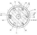
- FIG. 5 A part of the fuel injection device according to the second embodiment of the present disclosure is illustrated in FIG. 5.
- the second embodiment is different from the first embodiment in the configuration of the third cylindrical protrusion 231.
- the third cylinder protruding portion 231 has holes 235 and 236 instead of the grooves 233 and 234 shown in the first embodiment.
- the hole portions 235 and 236 are formed so as to connect the end surface on the valve seat 14 side and the end surface on the opposite side of the valve seat 14 on the radially inner side of the third tube portion screw portion 232 of the third tube portion projecting portion 231.
- five hole portions 235 are formed in the circumferential direction of the third cylindrical portion projecting portion 231 so as to be circular when viewed from the direction of the axis Ax1.
- One hole 236 is formed so as to have an oval shape along the arc when viewed from the direction of the axis Ax1.
- the hole 236 is formed larger than the hole 235.
- the holes 235 and 236 are formed so as to be substantially equidistant in the circumferential direction of the third cylindrical protrusion 231. That is, the holes 235 and 236 are formed at an interval of about 60 degrees in the circumferential direction of the third cylindrical protrusion 231.
- the holes 235 and 236 connect the space on the opposite side to the valve seat 14 of the third cylindrical protrusion 231 and the coil housing chamber 101.
- the bobbin extending portion 811 is inserted in the hole portion 236.
- the manufacturing method of the fuel injection device is different from the first embodiment in the coil assembly process and the molding process as follows.
- the coil 80 is assembled to the outside of the housing 20 so that the bobbin extending portion 811 is inserted into the hole 236.
- the heated thermoplastic resin is filled into the coil housing chamber 101 via the hole 235 and the outer wall of the third cylindrical portion 23 is covered with the heated thermoplastic resin to form the mold portion 83.
- the third cylindrical projecting portion 231 includes the coil housing chamber 101 that houses the coil 80 between the end surface on the valve seat 14 side, the inner wall of the yoke 90, and the outer wall of the housing 20. It has holes 235 and 236 that are formed and connect the end surface on the valve seat 14 side and the end surface on the opposite side of the valve seat 14 on the radially inner side of the third cylindrical thread portion 232. The periphery of the coil 80 in the coil housing chamber 101 is covered with resin.
- the hole portions 235 and 236 are formed on the inner side in the radial direction of the third tube portion screw portion 232 of the third tube portion protruding portion 231. Therefore, the third tube portion threaded portion 232 is formed so as to be continuous over the entire circumferential range of the third tube portion protruding portion 231 without being partly cut away in the circumferential direction as in the first embodiment. Has been. Therefore, the axial force F ⁇ b> 1 in the direction in which the first tube portion 21 and the third tube portion 23 approach each other can be made uniform over the entire circumferential range of the third tube portion screw portion 232.
- the hole 235 is formed in a circular shape, and the hole 236 is formed in an oval shape. Therefore, the holes 235 and 236 can be easily formed by, for example, a drill.
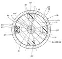
- FIG. 6 A part of the fuel injection device according to the third embodiment of the present disclosure is illustrated in FIG. 6.
- the third embodiment is different from the second embodiment in the configuration of the third cylindrical protrusion 231.
- the third cylinder protruding portion 231 has a hole 237 instead of the holes 235 and 236 shown in the second embodiment.
- the hole 237 is formed so as to connect the end surface on the valve seat 14 side and the end surface on the opposite side of the valve seat 14 on the radially inner side of the third tube portion screw portion 232 of the third tube portion projecting portion 231.
- four hole portions 237 are formed in the circumferential direction of the third tubular portion projecting portion 231 so as to have a shape obtained by removing the sector shape with the radius r2 from the sector shape with the radius r1 when viewed from the direction of the axis Ax1.
- r1 is smaller than the radius of the 3rd cylinder part protrusion part 231, and larger than r2 (refer FIG. 6).
- r2 is equivalent to half of the outer diameter of the cylindrical third tube portion 23.
- the hole portions 237 are formed so as to be substantially equidistant in the circumferential direction of the third cylinder protruding portion 231. That is, the hole portions 237 are formed at intervals of about 90 degrees in the circumferential direction of the third cylindrical portion protruding portion 231.
- the hole 237 connects the space on the opposite side of the valve seat 14 of the third cylindrical projecting portion 231 and the coil housing chamber 101.
- the bobbin extending portion 811 is inserted into one of the four hole portions 237.
- the manufacturing method of the fuel injection device is different from the second embodiment in the coil assembly process and the molding process as follows.
- the coil 80 is assembled to the outside of the housing 20 so that the bobbin extending portion 811 is inserted into the hole portion 237.
- the heated thermoplastic resin is filled into the coil housing chamber 101 via the hole 237 and the outer wall of the third cylindrical portion 23 is covered with the heated thermoplastic resin to form the mold portion 83.
- the third cylindrical projecting portion 231 includes the coil housing chamber 101 that houses the coil 80 between the end surface on the valve seat 14 side, the inner wall of the yoke 90, and the outer wall of the housing 20.
- a hole portion 237 is formed to connect the end surface on the valve seat 14 side and the end surface on the opposite side of the valve seat 14 on the radially inner side of the third tube portion screw portion 232.
- the periphery of the coil 80 in the coil housing chamber 101 is covered with resin.
- the hole portion 237 is formed on the inner side in the radial direction of the third cylindrical portion screw portion 232 of the third cylindrical portion protruding portion 231. Therefore, the third tube portion threaded portion 232 is formed so as to be continuous over the entire circumferential range of the third tube portion protruding portion 231 without being partly cut away in the circumferential direction as in the first embodiment. Has been. Therefore, as in the second embodiment, the axial force F1 in the direction in which the first tube portion 21 and the third tube portion 23 approach each other is made uniform over the entire circumferential range of the third tube portion screw portion 232. Can do.
- the four hole portions 237 have the same shape and are formed at equal intervals in the circumferential direction of the third tubular portion protruding portion 231. Therefore, it is possible to improve the balance in the circumferential direction of the third cylindrical projecting portion 231 of the magnetic circuit formed in the yoke 90 when the coil 80 is energized.
- FIG. 7 shows a part of the fuel injection device according to the fourth embodiment of the present disclosure.
- the fourth embodiment is particularly different from the third embodiment in the configuration of the first tube portion 21, the third tube portion 23, and the yoke 90.
- the first tube portion 21 has a first tube portion protruding portion 212 that protrudes annularly from the outer wall to the radially outer side.
- a first tube portion screw portion 213 is formed on the radially outer surface of the first tube portion protruding portion 212.
- 3rd cylinder part protrusion part 231 does not have the 3rd cylinder part screw part 232 shown in 3rd Embodiment.
- the third tubular portion projecting portion 231 has a third tubular portion locking surface 238 on the outer edge portion of the end surface opposite to the valve seat 14.
- the hole portion 237 is formed on the inner side in the radial direction of the third tube portion locking surface 238.
- the yoke 90 has a yoke upper protruding portion 93 that protrudes in an annular shape radially inward from an inner wall in the axial direction. On the surface of the yoke upper protrusion 93 on the valve seat 14 side, a yoke upper locking surface 931 facing the third tube portion locking surface 238 is formed.
- the yoke 90 has a yoke lower thread portion 94 that is formed on the inner wall of the end portion on the valve seat 14 side and can be screwed into the first tube portion thread portion 213.
- the yoke 90 has a yoke lower screw portion 94 screwed into the first tube portion screw portion 213 so that the yoke upper engagement surface 931 and the third tube portion engagement surface 238 are in contact with each other.
- the first tube portion 21 and the third tube portion 23 are in a state in which an axial force F1 that is a force along the axis Ax1 in a direction in which the first tube portion 21 and the third tube portion 23 approach each other is generated. ing. Therefore, a force in a direction contracting in the direction of the axis Ax1 from the first cylinder portion 21 and the third cylinder portion 23 acts on the second cylinder portion 22 forming the magnetic aperture portion 221.
- the yoke 90 has a yoke upper locking surface 931 locked by the third tube portion locking surface 238, and relative movement of the housing 20 toward the valve seat 14 is restricted.
- the manufacturing method of the fuel injection device is different from the third embodiment in the yoke assembling process and the yoke welding process as follows.
- the third cylinder portion is engaged so that the first cylinder portion 21 and the third cylinder portion 23 are in a state where an axial force F1 of a predetermined magnitude is generated in a direction in which the first cylinder portion 21 and the third cylinder portion 23 approach each other.
- the yoke upper locking surface 931 is brought into contact with the stop surface 238, the yoke lower screw portion 94 is screwed into the first tube portion screw portion 213, and the yoke 90 is assembled to the housing 20.
- connection part c6 between the first cylindrical protrusion 212 and the yoke 90 is welded.
- the valve seat 14 side portion of the first tube portion protruding portion 212 is welded to the valve seat 14 side portion and the yoke lower screw portion 94 of the yoke 90 is welded to the valve seat 14 side portion. Therefore, “the yoke 90 extends in the axial direction during welding and the axial force F1 decreases” can be suppressed.
- the first tube portion 21 has the first tube portion screw portion 213.
- the third cylinder part 23 has a third cylinder part locking surface 238.
- the yoke 90 is screwed to the yoke upper locking surface 931 that is locked to the third cylindrical portion locking surface 238 and the relative movement of the housing 20 to the valve seat 14 side is restricted, and to the first cylindrical portion screw portion 213.
- a yoke lower thread portion 94 is provided.
- the 1st cylinder part 21 and the yoke 90 are being fixed so that relative rotation is impossible. Therefore, “decrease in axial force F1 due to relative rotation between the first tube portion 21 and the yoke 90” can be suppressed.
- the third cylindrical portion 23 projects annularly outwardly from the outer wall in the radial direction on the side opposite to the valve seat 14 with respect to the coil 80, and the third cylindrical portion locking surface on the end surface opposite to the valve seat 14. It has the 3rd cylinder part projection part 231 in which 238 is formed.
- the third tubular portion projecting portion 231 forms a coil housing chamber 101 that houses the coil 80 between the end face on the valve seat 14 side, the inner wall of the yoke 90, and the outer wall of the housing 20, and the third tubular portion locking surface 238. Is provided with a hole 237 that connects the end face on the valve seat 14 side and the end face on the opposite side of the valve seat 14.
- the periphery of the coil 80 in the coil housing chamber 101 is covered with resin.
- the hole portion 237 is formed on the radially inner side of the third tube portion locking surface 238 of the third tube portion protruding portion 231. Therefore, the third cylindrical portion locking surface 238 is formed so as to be continuous over the entire circumferential range of the third cylindrical portion projecting portion 231 without being partly cut away in the circumferential direction. Therefore, the axial force F ⁇ b> 1 in the direction in which the first tube portion 21 and the third tube portion 23 approach each other can be made uniform over the entire circumferential range of the third tube portion locking surface 238.
- FIG. 8 A part of the fuel injection device according to the fifth embodiment of the present disclosure is illustrated in FIG. 8.
- the fifth embodiment is different from the fourth embodiment particularly in the configuration of the first tube portion 21 and the yoke 90.
- a first tube portion locking surface 211 is formed on the outer wall of the first tube portion 21 of the housing 20 as in the first embodiment.
- the yoke 90 includes a first yoke 901 and a second yoke 902.
- the first yoke 901 and the second yoke 902 are formed in a cylindrical shape and are coaxial.
- the first yoke 901 has a yoke lower locking surface 911 that is locked to the first tube portion locking surface 211 to restrict relative movement of the housing 20 to the opposite side of the valve seat 14. .
- the second yoke 902 is provided on the side opposite to the valve seat 14 with respect to the first yoke 901, and is locked to the third tube portion locking surface 238 of the third tube portion protruding portion 231, so that the valve with respect to the housing 20 is provided.
- a yoke upper locking surface 931 that restricts relative movement toward the seat 14 is provided.
- the first yoke 901 has a first yoke threaded portion 903 on the inner wall at the end opposite to the valve seat 14.
- the second yoke 902 has a second yoke screw portion 904 that can be screwed into the first yoke screw portion 903 on the outer wall of the end portion on the valve seat 14 side.
- the yoke lower locking surface 911 and the first tube portion locking surface 211 are in contact with each other, and the yoke upper locking surface 931 and the third tube portion locking surface 238 are in contact with each other.
- the yoke screw portion 903 and the second yoke screw portion 904 are screwed together.
- the first cylindrical portion 21 and the third cylindrical portion 23 are in a state where an axial force F1 that is a force along the axis Ax1 in a direction in which the first cylindrical portion 21 and the third cylindrical portion 23 approach each other is generated. Therefore, a force in a direction contracting in the direction of the axis Ax1 from the first cylinder portion 21 and the third cylinder portion 23 acts on the second cylinder portion 22 forming the magnetic aperture portion 221.
- the yoke 90 has a yoke lower locking surface 911 locked to the first tube portion locking surface 211, and relative movement of the housing 20 to the opposite side of the valve seat 14 is restricted.
- the yoke 90 has a yoke upper locking surface 931 locked by the third tube portion locking surface 238, and relative movement of the housing 20 toward the valve seat 14 is restricted.
- the manufacturing method of the fuel injection device is different from the fourth embodiment in the yoke assembly process as follows. Moreover, in this embodiment, the manufacturing method of a fuel injection apparatus does not include the yoke welding process shown in 4th Embodiment.
- the first cylinder part engagement is such that the first cylinder part 21 and the third cylinder part 23 are in a state where an axial force F1 of a predetermined magnitude is generated in a direction in which the first cylinder part 21 and the third cylinder part 23 approach each other.
- the yoke lower locking surface 911 of the first yoke 901 is brought into contact with the stop surface 211
- the yoke upper locking surface 931 of the second yoke 902 is brought into contact with the third tube portion locking surface 238, and the first yoke screw portion.
- 903 and the second yoke threaded portion 904 are screwed together, and the yoke 90 is assembled to the housing 20.
- the first tube portion 21 has the first tube portion locking surface 211.
- the third cylinder part 23 has a third cylinder part locking surface 238.
- the yoke 90 is locked to the first tube portion locking surface 211 so that the relative movement of the housing 20 to the side opposite to the valve seat 14 is restricted, and the third tube portion.
- the upper locking surface 931 on the yoke is restricted by being locked to the locking surface 238 so that the relative movement of the housing 20 toward the valve seat 14 is restricted.
- the yoke 90 includes the first yoke 901 on which the yoke lower locking surface 911 is formed and the second yoke 902 on which the yoke upper locking surface 931 is formed.
- the first yoke 901 has a first yoke threaded portion 903 on the inner wall.
- the second yoke 902 has a second yoke screw portion 904 that is screwed to the first yoke screw portion 903 on the outer wall.
- FIG. 9 shows a part of the fuel injection device according to the sixth embodiment of the present disclosure.
- the sixth embodiment is different from the fifth embodiment particularly in the configuration of the yoke 90.
- the yoke 90 is formed in a cylindrical shape and has a yoke upper caulking portion 95 that protrudes annularly radially inward from an inner wall in the axial direction.
- a yoke upper locking surface 931 facing the third tube portion locking surface 238 is formed on the surface of the yoke upper caulking portion 95 on the valve seat 14 side.
- the yoke 90 is disposed on the yoke so that the yoke lower locking surface 911 and the first tube portion locking surface 211 are in contact with each other, and the yoke upper locking surface 931 and the third tube portion locking surface 238 are in contact with each other.
- the caulking portion 95 is caulked to the third tube portion protruding portion 231.
- the first tube portion 21 and the third tube portion 23 are in a state in which an axial force F1 that is a force along the axis Ax1 in a direction in which the first tube portion 21 and the third tube portion 23 approach each other is generated. ing. Therefore, a force in a direction contracting in the direction of the axis Ax1 from the first cylinder portion 21 and the third cylinder portion 23 acts on the second cylinder portion 22 forming the magnetic aperture portion 221.
- the yoke 90 has a yoke lower locking surface 911 locked to the first tube portion locking surface 211, and relative movement of the housing 20 to the opposite side of the valve seat 14 is restricted.
- the yoke 90 has a yoke upper locking surface 931 locked by the third tube portion locking surface 238, and relative movement of the housing 20 toward the valve seat 14 is restricted.
- the manufacturing method of the fuel injection device is different from the fifth embodiment in the yoke assembling process as follows.
- the first cylinder part engagement is such that the first cylinder part 21 and the third cylinder part 23 are in a state where an axial force F1 of a predetermined magnitude is generated in a direction in which the first cylinder part 21 and the third cylinder part 23 approach each other.
- the yoke lower locking surface 911 is brought into contact with the stop surface 211 and, for example, a jig is pressed from outside in the radial direction of the yoke 90, so that the yoke upper locking surface 931 comes into contact with the third tube portion locking surface 238.
- a caulking portion 95 is formed, and the yoke 90 is caulked to the third cylindrical portion protruding portion 231.
- the first tube portion 21 has the first tube portion locking surface 211.
- the third cylinder part 23 has a third cylinder part locking surface 238.
- the yoke 90 is locked to the first tube portion locking surface 211 so that the relative movement of the housing 20 to the side opposite to the valve seat 14 is restricted, and the third tube portion.
- the upper locking surface 931 on the yoke is restricted by being locked to the locking surface 238 so that the relative movement of the housing 20 toward the valve seat 14 is restricted.
- the yoke 90 is assembled to the housing 20 by being caulked by the third cylindrical projecting portion 231. Therefore, the yoke 90 can be assembled to the housing 20 relatively easily.
- FIG. 10 shows a part of the fuel injection device according to the seventh embodiment of the present disclosure.
- the seventh embodiment is different from the fifth embodiment particularly in the configuration of the yoke 90.
- the first tube portion 21 has a first tube portion locking surface 211.
- the yoke 90 is formed in a cylindrical shape, and has a yoke lower caulking portion 96 that protrudes annularly radially inward from the end portion on the valve seat 14 side.
- a yoke lower locking surface 911 facing the first tube portion locking surface 211 of the first tube portion 21 is formed on the surface of the yoke lower caulking portion 96 on the opposite side to the valve seat 14.
- the yoke 90 is arranged so that the yoke upper locking surface 931 and the third tube portion locking surface 238 are in contact with each other, and the yoke lower locking surface 911 and the first tube portion locking surface 211 are in contact with each other.
- the caulking portion 96 is caulked to the first tube portion 21.
- the first tube portion 21 and the third tube portion 23 are in a state in which an axial force F1 that is a force along the axis Ax1 in a direction in which the first tube portion 21 and the third tube portion 23 approach each other is generated. ing. Therefore, a force in a direction contracting in the direction of the axis Ax1 from the first cylinder portion 21 and the third cylinder portion 23 acts on the second cylinder portion 22 forming the magnetic aperture portion 221.
- the yoke 90 has a yoke lower locking surface 911 locked to the first tube portion locking surface 211, and relative movement of the housing 20 to the opposite side of the valve seat 14 is restricted.
- the yoke 90 has a yoke upper locking surface 931 locked by the third tube portion locking surface 238, and relative movement of the housing 20 toward the valve seat 14 is restricted.
- the manufacturing method of the fuel injection device is different from the fifth embodiment in the yoke assembling process as follows.
- the third cylinder portion is engaged so that the first cylinder portion 21 and the third cylinder portion 23 are in a state where an axial force F1 of a predetermined magnitude is generated in a direction in which the first cylinder portion 21 and the third cylinder portion 23 approach each other.
- the yoke upper locking surface 931 is brought into contact with the stop surface 238 and, for example, a jig is pressed from the radially outer end of the yoke 90 on the valve seat 14 side, and the yoke lower locking surface 911 is locked to the first tube portion.
- a yoke lower caulking portion 96 is formed so as to contact the surface 211, and the yoke 90 is caulked to the first tube portion 21.
- the first tube portion 21 has the first tube portion locking surface 211.
- the third cylinder part 23 has a third cylinder part locking surface 238.
- the yoke 90 is locked to the first tube portion locking surface 211 so that the relative movement of the housing 20 to the side opposite to the valve seat 14 is restricted, and the third tube portion.
- the upper locking surface 931 on the yoke is restricted by being locked to the locking surface 238 so that the relative movement of the housing 20 toward the valve seat 14 is restricted.
- the yoke 90 is assembled to the housing 20 by being caulked to the first cylindrical portion 21. Therefore, the yoke 90 can be assembled to the housing 20 relatively easily.
- FIG. 11 shows a part of the fuel injection device according to the eighth embodiment of the present disclosure.
- the eighth embodiment is particularly different from the first embodiment in the configuration of the first tube portion 21, the second tube portion 22, the third tube portion 23, and the yoke 90.
- the first tube portion 21 and the second tube portion 22 are integrally formed of a magnetic material such as ferritic stainless steel, for example. That is, the 1st cylinder part 21 and the 2nd cylinder part 22 are integrally formed with the same material.
- the 2nd cylinder part 22 has the magnetic aperture part 221 in a part of axial direction.
- the magnetic aperture portion 221 is thinner than other portions of the second cylinder portion 22 in the axial direction.
- the end of the second tube portion 22 on the third tube portion 23 side is welded to the third tube portion 23.
- the third cylindrical portion 23 is formed separately from the fixed core body 51 of the fixed core 50 by a separate member.
- the fixed core main body 51 is provided inside the third cylindrical portion 23 by press-fitting, for example.
- the third cylinder thread portion 232 is formed over the entire axial range of the third cylinder protrusion 231.
- a yoke upper screw portion 92 that can be screwed into the third tube portion screw portion 232 is formed on the inner wall in the axial direction of the yoke 90.
- the manufacturing method of the fuel injection device is different from the first embodiment in the housing welding process as follows. Further, in the present embodiment, the method for manufacturing the fuel injection device includes the fixed core press-fitting step and does not include the yoke welding step shown in the first embodiment.
- the fixed core body 51 is press-fitted inside the third cylindrical portion 23.
- the second cylindrical portion 22 and the third cylindrical portion 23 are welded in a state where the needle 30 and the movable core 40 are accommodated inside the housing 20.
- the coil 80 is assembled to the outside of the housing 20 so that the bobbin extending portion 811 is positioned in the groove portion 234.
- the first cylinder part engagement is such that the first cylinder part 21 and the third cylinder part 23 are in a state where an axial force F1 of a predetermined magnitude is generated in a direction in which the first cylinder part 21 and the third cylinder part 23 approach each other.
- the yoke lower locking surface 911 is brought into contact with the stop surface 211, the yoke upper screw portion 92 is screwed into the third tube portion screw portion 232, and the yoke 90 is assembled to the housing 20.
- the second tube portion 22 is formed integrally with the first tube portion 21. Therefore, the number of members and assembly man-hours can be reduced. Also in the present embodiment, the yoke 90 is provided so that the first cylindrical portion 21 and the third cylindrical portion 23 generate an axial force F1 in a direction in which the first cylindrical portion 21 and the third cylindrical portion 23 approach each other. Therefore, a force in a direction contracting in the direction of the axis Ax1 from the first cylinder portion 21 and the third cylinder portion 23 acts on the second cylinder portion 22 forming the magnetic aperture portion 221.
- the second cylindrical portion 22 may be formed integrally with the third cylindrical portion 23 if the magnetic throttle portion 221 is formed by, for example, thinning. Good. Further, the second cylinder part 22 may be formed integrally with the first cylinder part 21 and the third cylinder part 23.
- the first yoke screw portion 903 is formed on the inner wall of the first yoke 901, and the second yoke screw portion 904 is formed on the outer wall of the second yoke 902.
- the first yoke screw portion 903 is formed on the outer wall of the first yoke 901
- the second yoke screw portion 904 is formed on the inner wall of the second yoke 902. Good.
- the housing 20 may be formed of a metal other than stainless steel, such as iron or aluminum.
- the example in which the nozzle 10 and the first tube portion 21 are formed separately has been shown.
- the nozzle 10 and the 1st cylinder part 21 are good also as being integrally formed.
- the gap forming member 60 may not be provided. In this case, no axial gap is formed between the contact surface 34 of the flange 33 and the movable core 40 when the valve is closed. In other embodiments of the present disclosure, the movable core 40 may be formed integrally with the needle 30. In another embodiment of the present disclosure, at least one of the spring seat portion 291, the fixing portion 292, the tubular portion 293, and the spring 73 may not be provided.
- the screw coupling member 26 may be screwed into the fuel pipe 6 so that the cylinder member 25 and the fuel pipe 6 are in a tightly coupled state.
- cylindrical member 25 and the screw coupling member 26 may not be provided.
- the fuel injection device may be attached to the engine 2 so as to be pressed against the step surface of the attachment hole 5 with a predetermined force, for example, by a fuel rail distribution pipe or the like. .
- the present disclosure is not limited to a direct injection type gasoline engine, and may be applied to, for example, a port injection type gasoline engine or a diesel engine.
Landscapes
- Engineering & Computer Science (AREA)
- Chemical & Material Sciences (AREA)
- Combustion & Propulsion (AREA)
- Mechanical Engineering (AREA)
- General Engineering & Computer Science (AREA)
- Physics & Mathematics (AREA)
- Electromagnetism (AREA)
- Fuel-Injection Apparatus (AREA)
Priority Applications (3)
| Application Number | Priority Date | Filing Date | Title |
|---|---|---|---|
| US15/763,614 US10718302B2 (en) | 2015-10-02 | 2016-09-12 | Fuel injection device |
| CN201680058085.6A CN108138713A (zh) | 2015-10-02 | 2016-09-12 | 燃料喷射装置 |
| DE112016004490.9T DE112016004490T5 (de) | 2015-10-02 | 2016-09-12 | Kraftstoffeinspritzvorrichtung |
Applications Claiming Priority (2)
| Application Number | Priority Date | Filing Date | Title |
|---|---|---|---|
| JP2015196824A JP6380323B2 (ja) | 2015-10-02 | 2015-10-02 | 燃料噴射装置 |
| JP2015-196824 | 2015-10-02 |
Publications (1)
| Publication Number | Publication Date |
|---|---|
| WO2017056940A1 true WO2017056940A1 (ja) | 2017-04-06 |
Family
ID=58423537
Family Applications (1)
| Application Number | Title | Priority Date | Filing Date |
|---|---|---|---|
| PCT/JP2016/076789 Ceased WO2017056940A1 (ja) | 2015-10-02 | 2016-09-12 | 燃料噴射装置 |
Country Status (5)
| Country | Link |
|---|---|
| US (1) | US10718302B2 (enExample) |
| JP (1) | JP6380323B2 (enExample) |
| CN (1) | CN108138713A (enExample) |
| DE (1) | DE112016004490T5 (enExample) |
| WO (1) | WO2017056940A1 (enExample) |
Families Citing this family (4)
| Publication number | Priority date | Publication date | Assignee | Title |
|---|---|---|---|---|
| JP6677194B2 (ja) | 2017-03-03 | 2020-04-08 | 株式会社デンソー | 燃料噴射弁 |
| JP6708235B2 (ja) | 2017-09-29 | 2020-06-10 | 株式会社デンソー | 燃料噴射弁 |
| JP7028197B2 (ja) * | 2019-01-17 | 2022-03-02 | 株式会社デンソー | 燃料噴射弁 |
| DE102023000408B3 (de) | 2023-02-09 | 2024-07-25 | Deutz Aktiengesellschaft | Verbindungsanordnung zum Verbinden einer Kraftstoffleitung mit einem lnjektor einer Brennkraftmaschine |
Citations (6)
| Publication number | Priority date | Publication date | Assignee | Title |
|---|---|---|---|---|
| JP2006017026A (ja) * | 2004-07-01 | 2006-01-19 | Toyota Motor Corp | 燃料噴射弁 |
| JP2007218205A (ja) * | 2006-02-17 | 2007-08-30 | Hitachi Ltd | 電磁燃料噴射弁及びその組立て方法 |
| JP2012515290A (ja) * | 2009-01-13 | 2012-07-05 | ローベルト ボツシユ ゲゼルシヤフト ミツト ベシユレンクテル ハフツング | 燃料噴射弁 |
| JP2014092060A (ja) * | 2012-11-02 | 2014-05-19 | Keihin Corp | 電磁式燃料噴射弁 |
| JP2014125972A (ja) * | 2012-12-26 | 2014-07-07 | Denso Corp | 燃料噴射弁 |
| JP2014227958A (ja) * | 2013-05-24 | 2014-12-08 | 日立オートモティブシステムズ株式会社 | 燃料噴射弁 |
Family Cites Families (7)
| Publication number | Priority date | Publication date | Assignee | Title |
|---|---|---|---|---|
| JP3816801B2 (ja) * | 2000-01-26 | 2006-08-30 | 株式会社日立製作所 | 電磁式燃料噴射弁 |
| JP3734702B2 (ja) * | 2000-10-17 | 2006-01-11 | 株式会社日立製作所 | 電磁式燃料噴射弁 |
| DE102007026891A1 (de) | 2007-06-11 | 2008-12-18 | Robert Bosch Gmbh | Steuerventil, insbesondere für einen Kraftstoffinjektor einer Brennkraftmaschine |
| JP5509901B2 (ja) * | 2010-02-12 | 2014-06-04 | 株式会社デンソー | 燃料噴射弁 |
| JP5402713B2 (ja) * | 2010-02-18 | 2014-01-29 | 株式会社デンソー | 燃料噴射弁 |
| JP6318605B2 (ja) * | 2013-12-20 | 2018-05-09 | 株式会社デンソー | 溶接部を有する継手構造の組付構造 |
| JP6347646B2 (ja) | 2014-04-03 | 2018-06-27 | 住友ゴム工業株式会社 | 空気入りタイヤ |
-
2015
- 2015-10-02 JP JP2015196824A patent/JP6380323B2/ja active Active
-
2016
- 2016-09-12 US US15/763,614 patent/US10718302B2/en active Active
- 2016-09-12 WO PCT/JP2016/076789 patent/WO2017056940A1/ja not_active Ceased
- 2016-09-12 CN CN201680058085.6A patent/CN108138713A/zh active Pending
- 2016-09-12 DE DE112016004490.9T patent/DE112016004490T5/de not_active Ceased
Patent Citations (6)
| Publication number | Priority date | Publication date | Assignee | Title |
|---|---|---|---|---|
| JP2006017026A (ja) * | 2004-07-01 | 2006-01-19 | Toyota Motor Corp | 燃料噴射弁 |
| JP2007218205A (ja) * | 2006-02-17 | 2007-08-30 | Hitachi Ltd | 電磁燃料噴射弁及びその組立て方法 |
| JP2012515290A (ja) * | 2009-01-13 | 2012-07-05 | ローベルト ボツシユ ゲゼルシヤフト ミツト ベシユレンクテル ハフツング | 燃料噴射弁 |
| JP2014092060A (ja) * | 2012-11-02 | 2014-05-19 | Keihin Corp | 電磁式燃料噴射弁 |
| JP2014125972A (ja) * | 2012-12-26 | 2014-07-07 | Denso Corp | 燃料噴射弁 |
| JP2014227958A (ja) * | 2013-05-24 | 2014-12-08 | 日立オートモティブシステムズ株式会社 | 燃料噴射弁 |
Also Published As
| Publication number | Publication date |
|---|---|
| US10718302B2 (en) | 2020-07-21 |
| JP6380323B2 (ja) | 2018-08-29 |
| US20180291850A1 (en) | 2018-10-11 |
| JP2017067055A (ja) | 2017-04-06 |
| DE112016004490T5 (de) | 2018-06-21 |
| CN108138713A (zh) | 2018-06-08 |
Similar Documents
| Publication | Publication Date | Title |
|---|---|---|
| US11047352B2 (en) | Fuel injection valve | |
| JP6483574B2 (ja) | 燃料噴射装置 | |
| US20190242347A1 (en) | Fuel injection device | |
| WO2016042753A1 (ja) | 燃料噴射弁 | |
| JP2019090427A (ja) | 燃料噴射弁 | |
| JP6380323B2 (ja) | 燃料噴射装置 | |
| WO2017037973A1 (ja) | 燃料噴射装置 | |
| JP6471618B2 (ja) | 燃料噴射装置 | |
| JP2017089425A (ja) | 燃料噴射装置 | |
| JP6421730B2 (ja) | 燃料噴射装置 | |
| JP6613973B2 (ja) | 燃料噴射装置 | |
| US9334842B2 (en) | Fuel injection valve for internal combustion engine | |
| JP2018059514A (ja) | 燃料噴射弁 | |
| JP6547885B2 (ja) | 燃料噴射装置 | |
| JP6669282B2 (ja) | 燃料噴射装置 | |
| JP2015218664A (ja) | 燃料噴射弁 | |
| JP2015224597A (ja) | 燃料噴射弁 | |
| US11560867B2 (en) | Fuel flow passage member and fuel injection valve including the same | |
| JP6531610B2 (ja) | 燃料噴射装置、および、燃料噴射装置の製造方法 | |
| JP2017186979A (ja) | 燃料噴射装置 | |
| JP2017210919A (ja) | 燃料噴射装置 | |
| JP2017053241A (ja) | 燃料噴射装置 |
Legal Events
| Date | Code | Title | Description |
|---|---|---|---|
| 121 | Ep: the epo has been informed by wipo that ep was designated in this application |
Ref document number: 16851114 Country of ref document: EP Kind code of ref document: A1 |
|
| WWE | Wipo information: entry into national phase |
Ref document number: 15763614 Country of ref document: US |
|
| WWE | Wipo information: entry into national phase |
Ref document number: 112016004490 Country of ref document: DE |
|
| 122 | Ep: pct application non-entry in european phase |
Ref document number: 16851114 Country of ref document: EP Kind code of ref document: A1 |