WO2017056940A1 - 燃料噴射装置 - Google Patents
燃料噴射装置 Download PDFInfo
- Publication number
- WO2017056940A1 WO2017056940A1 PCT/JP2016/076789 JP2016076789W WO2017056940A1 WO 2017056940 A1 WO2017056940 A1 WO 2017056940A1 JP 2016076789 W JP2016076789 W JP 2016076789W WO 2017056940 A1 WO2017056940 A1 WO 2017056940A1
- Authority
- WO
- WIPO (PCT)
- Prior art keywords
- yoke
- valve seat
- tube portion
- fuel
- cylinder
- Prior art date
- Legal status (The legal status is an assumption and is not a legal conclusion. Google has not performed a legal analysis and makes no representation as to the accuracy of the status listed.)
- Ceased
Links
Images





Classifications
-
- F—MECHANICAL ENGINEERING; LIGHTING; HEATING; WEAPONS; BLASTING
- F02—COMBUSTION ENGINES; HOT-GAS OR COMBUSTION-PRODUCT ENGINE PLANTS
- F02M—SUPPLYING COMBUSTION ENGINES IN GENERAL WITH COMBUSTIBLE MIXTURES OR CONSTITUENTS THEREOF
- F02M51/00—Fuel-injection apparatus characterised by being operated electrically
- F02M51/06—Injectors peculiar thereto with means directly operating the valve needle
- F02M51/061—Injectors peculiar thereto with means directly operating the valve needle using electromagnetic operating means
- F02M51/0625—Injectors peculiar thereto with means directly operating the valve needle using electromagnetic operating means characterised by arrangement of mobile armatures
- F02M51/0664—Injectors peculiar thereto with means directly operating the valve needle using electromagnetic operating means characterised by arrangement of mobile armatures having a cylindrically or partly cylindrically shaped armature, e.g. entering the winding; having a plate-shaped or undulated armature entering the winding
- F02M51/0671—Injectors peculiar thereto with means directly operating the valve needle using electromagnetic operating means characterised by arrangement of mobile armatures having a cylindrically or partly cylindrically shaped armature, e.g. entering the winding; having a plate-shaped or undulated armature entering the winding the armature having an elongated valve body attached thereto
-
- F—MECHANICAL ENGINEERING; LIGHTING; HEATING; WEAPONS; BLASTING
- F02—COMBUSTION ENGINES; HOT-GAS OR COMBUSTION-PRODUCT ENGINE PLANTS
- F02M—SUPPLYING COMBUSTION ENGINES IN GENERAL WITH COMBUSTIBLE MIXTURES OR CONSTITUENTS THEREOF
- F02M51/00—Fuel-injection apparatus characterised by being operated electrically
- F02M51/06—Injectors peculiar thereto with means directly operating the valve needle
-
- F—MECHANICAL ENGINEERING; LIGHTING; HEATING; WEAPONS; BLASTING
- F02—COMBUSTION ENGINES; HOT-GAS OR COMBUSTION-PRODUCT ENGINE PLANTS
- F02M—SUPPLYING COMBUSTION ENGINES IN GENERAL WITH COMBUSTIBLE MIXTURES OR CONSTITUENTS THEREOF
- F02M51/00—Fuel-injection apparatus characterised by being operated electrically
- F02M51/06—Injectors peculiar thereto with means directly operating the valve needle
- F02M51/061—Injectors peculiar thereto with means directly operating the valve needle using electromagnetic operating means
- F02M51/0614—Injectors peculiar thereto with means directly operating the valve needle using electromagnetic operating means characterised by arrangement of electromagnets or fixed armature
-
- F—MECHANICAL ENGINEERING; LIGHTING; HEATING; WEAPONS; BLASTING
- F02—COMBUSTION ENGINES; HOT-GAS OR COMBUSTION-PRODUCT ENGINE PLANTS
- F02M—SUPPLYING COMBUSTION ENGINES IN GENERAL WITH COMBUSTIBLE MIXTURES OR CONSTITUENTS THEREOF
- F02M55/00—Fuel-injection apparatus characterised by their fuel conduits or their venting means; Arrangements of conduits between fuel tank and pump F02M37/00
- F02M55/004—Joints; Sealings
-
- F—MECHANICAL ENGINEERING; LIGHTING; HEATING; WEAPONS; BLASTING
- F02—COMBUSTION ENGINES; HOT-GAS OR COMBUSTION-PRODUCT ENGINE PLANTS
- F02M—SUPPLYING COMBUSTION ENGINES IN GENERAL WITH COMBUSTIBLE MIXTURES OR CONSTITUENTS THEREOF
- F02M55/00—Fuel-injection apparatus characterised by their fuel conduits or their venting means; Arrangements of conduits between fuel tank and pump F02M37/00
- F02M55/004—Joints; Sealings
- F02M55/005—Joints; Sealings for high pressure conduits, e.g. connected to pump outlet or to injector inlet
-
- F—MECHANICAL ENGINEERING; LIGHTING; HEATING; WEAPONS; BLASTING
- F02—COMBUSTION ENGINES; HOT-GAS OR COMBUSTION-PRODUCT ENGINE PLANTS
- F02M—SUPPLYING COMBUSTION ENGINES IN GENERAL WITH COMBUSTIBLE MIXTURES OR CONSTITUENTS THEREOF
- F02M51/00—Fuel-injection apparatus characterised by being operated electrically
- F02M51/005—Arrangement of electrical wires and connections, e.g. wire harness, sockets, plugs; Arrangement of electronic control circuits in or on fuel injection apparatus
Definitions
- the present disclosure relates to a fuel injection device that injects and supplies fuel to an internal combustion engine.
- a nozzle holder that constitutes a part of a housing is press-fitted into a fixed core.
- the fixed core and the nozzle holder are joined by welding at the press-fitting position.
- the nozzle holder is formed with a magnetic throttle part having a thin part, and the magnetic throttle part is press-fitted into the fixed core and joined to the fixed core by welding.
- the fixed core and the nozzle holder are arranged in the axial direction at the welded portion between the fixed core and the nozzle holder or at the thin magnetic throttle portion. A force in the direction of leaving acts. If the pressure of the fuel in the fuel passage in the apparatus is excessive, stress concentrates on the welded portion or the magnetic throttle part between the fixed core and the nozzle holder, and the welded part or the magnetic throttle part may be broken. If the welded part or the magnetic restrictor is broken, the fuel in the fuel passage may leak to the outside. Therefore, in the fuel injection device of Patent Document 1, it is difficult to inject high-pressure fuel due to the structure.
- This disclosure is intended to provide a fuel injection device capable of injecting high-pressure fuel with high accuracy while suppressing fuel leakage.
- the fuel injection device of the present disclosure includes a nozzle, a housing, a needle, a movable core, a fixed core, a valve seat side urging member, a yoke, and a coil.
- the nozzle has an injection hole through which fuel is injected and a valve seat formed in an annular shape around the injection hole.
- the housing has a first cylinder part whose one end is connected to the nozzle, a second cylinder part whose one end is connected to the other end of the first cylinder part and forms a magnetic throttle part in at least a part in the axial direction, and one end which is the second cylinder.
- a third cylinder connected to the other end of the nozzle, and a fuel passage that is formed inside the first cylinder, the second cylinder, and the third cylinder so as to communicate with the nozzle hole and guides fuel to the nozzle hole. is doing.
- the needle has a rod-shaped needle body and a seal portion formed in an annular shape at one end of the needle body so as to be in contact with the valve seat, and when the seal portion is separated from the valve seat or comes into contact with the valve seat, the nozzle hole Open and close.
- the movable core is provided so as to reciprocate in the housing together with the needle.
- the fixed core is provided on the side opposite to the valve seat with respect to the movable core inside the second cylinder part and the third cylinder part.
- the valve seat side biasing member can bias the needle and the movable core toward the valve seat.
- the yoke is formed in a cylindrical shape, one end side is connected to the first tube portion, the other end side is connected to the third tube portion, and the first tube portion and the third tube portion are connected to the first tube portion and the third tube portion.
- the coil is provided between the housing and the yoke.
- a magnetic circuit is formed in the first cylindrical portion, the movable core, the fixed core, the third cylindrical portion, and the yoke, and the movable core is attracted to the fixed core side. It is possible to move the needle away from the valve seat.
- the yoke is provided in the first tube portion and the third tube portion so as to generate an axial force in a direction in which the first tube portion and the third tube portion approach each other. Therefore, a force in a direction contracting in the axial direction from the first and third cylindrical portions acts on the second cylindrical portion forming the magnetic aperture portion.
- the connection portion between the second tube portion and the first tube portion, the connection portion between the second tube portion and the third tube portion, or the magnetic throttle portion can be suppressed.
- the force in the direction of contracting in the axial direction from the first cylinder part and the third cylinder part acts on the second cylinder part forming the magnetic throttle part, the pressure of the fuel in the fuel passage Even if the height increases, it is possible to suppress the position of the magnetic aperture portion relative to the fixed core from shifting in the axial direction. Therefore, it can suppress that the magnitude
- the fuel injection device can inject high-pressure fuel with high accuracy while suppressing fuel leakage.
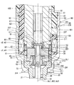
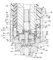
- FIG. 1 is a cross-sectional view illustrating a fuel injection device according to a first embodiment of the present disclosure.
- FIG. 2 is a cross-sectional view showing a fuel inlet portion and its vicinity of the fuel injection device according to the first embodiment of the present disclosure.
- FIG. 3 is a cross-sectional view showing a yoke and its vicinity of the fuel injection device according to the first embodiment of the present disclosure.
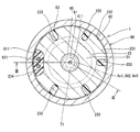
- 4 is a cross-sectional view taken along line IV-IV in FIG.
- FIG. 5 is a cross-sectional view showing a third tubular portion protruding portion and its vicinity of a fuel injection device according to a second embodiment of the present disclosure.
- FIG. 6 is a cross-sectional view showing a third tubular portion protruding portion and its vicinity of a fuel injection device according to a third embodiment of the present disclosure.
- FIG. 7 is a cross-sectional view illustrating a yoke and its vicinity of a fuel injection device according to a fourth embodiment of the present disclosure.
- FIG. 8 is a cross-sectional view illustrating a yoke and its vicinity of a fuel injection device according to a fifth embodiment of the present disclosure.
- FIG. 9 is a cross-sectional view showing a yoke and its vicinity of a fuel injection device according to a sixth embodiment of the present disclosure.
- FIG. 6 is a cross-sectional view showing a third tubular portion protruding portion and its vicinity of a fuel injection device according to a third embodiment of the present disclosure.
- FIG. 7 is a cross-sectional view illustrating a yoke and its vicinity of a fuel injection device according to a fourth embodiment of the present disclosure.
- FIG. 10 is a cross-sectional view showing a yoke and its vicinity of a fuel injection device according to a seventh embodiment of the present disclosure.
- FIG. 11 is a cross-sectional view showing a yoke and its vicinity of a fuel injection device according to an eighth embodiment of the present disclosure.
- FIG. 1 A fuel injection valve according to a first embodiment of the present disclosure is shown in FIG.
- the fuel injection device 1 is used in, for example, a direct injection gasoline engine (hereinafter referred to as “engine”) 2 as an internal combustion engine, and injects and supplies gasoline as fuel to the engine 2.
- engine direct injection gasoline engine
- the fuel injection device 1 includes a nozzle 10, a housing 20, a needle 30, a movable core 40, a fixed core 50, a gap forming member 60, a spring 71 as a valve seat side biasing member, a coil 80, a yoke 90, an inlet portion 24, a filter. 241, a cylindrical member 25, a screw coupling member 26, and the like.
- the nozzle 10 is formed of a material having a relatively high hardness such as martensitic stainless steel.
- the nozzle 10 is subjected to a quenching process so as to have a predetermined hardness.
- the nozzle 10 has a nozzle cylinder part 11 and a nozzle bottom part 12 that closes one end of the nozzle cylinder part 11.
- the nozzle bottom 12 is formed with a plurality of nozzle holes 13 that connect the surface on the nozzle tube portion 11 side and the surface on the opposite side of the nozzle tube portion 11.
- An annular valve seat 14 is formed around the nozzle hole 13 on the surface of the nozzle bottom portion 12 on the nozzle cylinder portion 11 side.
- the housing 20 includes a first cylinder part 21, a second cylinder part 22, a third cylinder part 23, and the like.
- the first cylinder part 21, the second cylinder part 22, and the third cylinder part 23 are all formed in a substantially cylindrical shape.
- the 1st cylinder part 21, the 2nd cylinder part 22, and the 3rd cylinder part 23 are arrange
- the 2nd cylinder part 22, the 1st cylinder part 21, and the 3rd cylinder part 23 are connected by welding, for example.
- a connection portion between the second tube portion 22 and the first tube portion 21 is indicated by c1
- a connection portion between the second tube portion 22 and the third tube portion 23 is indicated by c2.
- connection part c1 a melted part w1 is formed in which a part of the second cylinder part 22 and a part of the first cylinder part 21 are melted and cooled by welding.
- the connecting portion c2 is formed with a melted portion w2 in which a part of the second cylinder part 22 and a part of the third cylinder part 23 are melted and cooled by welding.
- the first cylinder part 21 and the third cylinder part 23 are made of a magnetic material such as ferritic stainless steel and are subjected to magnetic stabilization treatment.
- the 1st cylinder part 21 and the 3rd cylinder part 23 have comparatively low hardness.
- the 2nd cylinder part 22 is formed with nonmagnetic materials, such as austenitic stainless steel, for example. That is, the 2nd cylinder part 22 forms the magnetic aperture part 221 in all the axial directions.
- the hardness of the second cylinder part 22 is higher than the hardness of the first cylinder part 21 and the third cylinder part 23.
- the end of the first tube portion 21 opposite to the second tube portion 22 is joined to the end of the nozzle tube portion 11 opposite to the nozzle bottom 12.
- the 1st cylinder part 21 and the nozzle 10 are connected by welding, for example.
- the connection part of the 1st cylinder part 21 and the nozzle 10 is shown by c3.
- a melted part w3 is formed in which a part of the first cylinder part 21 and a part of the nozzle 10 are melted and cooled and solidified by welding.
- the inlet portion 24 is formed in a cylindrical shape from a metal such as stainless steel.
- the inlet portion 24 is provided so that one end thereof is connected to the radially inner side of the end portion of the third cylinder portion 23 opposite to the second cylinder portion 22.
- the inlet part 24 and the 3rd cylinder part 23 are integrally formed with the same material.
- the boundary between the inlet portion 24 and the third cylindrical portion 23 is indicated by a two-dot chain line.
- the cylindrical member 25 is provided on the opposite side of the inlet portion 24 from the third cylindrical portion 23.
- the cylindrical member 25 is formed in a cylindrical shape from a metal such as stainless steel.
- the cylindrical member 25 is provided so that one end thereof is connected to the radially outer side of the end portion of the inlet portion 24 opposite to the third cylindrical portion 23.
- the cylinder member 25 and the inlet part 24 are connected by welding, for example.
- FIG. 1 the connection part of the cylinder member 25 and the inlet part 24 is shown by c4.
- the connecting portion c4 is formed with a melted portion w4 in which a part of the cylindrical member 25 and a part of the inlet portion 24 are melted and cooled by welding.
- a threaded portion 251 is formed on the outer wall of the end portion of the cylindrical member 25 opposite to the inlet portion 24.
- a fuel pipe 6 through which fuel from the outside flows is connected to an end portion of the cylindrical member 25 opposite to the inlet portion 24.
- a protruding portion 7 is formed that protrudes annularly outward in the radial direction.
- a locking surface 8 is formed on the end surface of the protruding portion 7 opposite to the cylindrical member 25.
- the screw coupling member 26 is formed in a cylindrical shape from a metal such as stainless steel.
- a screw portion 261 that can be screwed into the screw portion 251 is formed on the inner wall of one end portion of the screw coupling member 26.
- a protruding portion 262 that protrudes radially inward is formed at the other end of the screw coupling member 26.
- a locking surface 263 is formed on the end surface of the protruding portion 262 on the screw portion 261 side.
- the screw coupling member 26 is in a state in which the end surface on the opposite side of the inlet portion 24 of the cylinder member 25 and the end surface on the cylinder member 25 side of the fuel pipe 6 are in contact, and the locking surface 263 and the locking surface 8 are in contact
- the screw part 261 is screwed to the screw part 251 so that At this time, the cylindrical member 25 and the fuel pipe 6 are in a state in which an axial force in a direction in which the cylindrical member 25 and the fuel pipe 6 approach each other is applied.
- the end surface of the cylinder member 25 opposite to the inlet portion 24 and the end surface of the fuel pipe 6 on the cylinder member 25 side are brought into close contact with each other.
- a fuel passage 100 is formed inside the housing 20 and the nozzle cylinder 11.
- the fuel passage 100 communicates with the nozzle hole 13. Thereby, fuel from the outside such as a fuel supply source flows into the fuel passage 100 via the fuel pipe 6, the cylindrical member 25, and the inlet portion 24.
- the fuel passage 100 guides fuel to the nozzle hole 13.
- the inlet portion 24 and the cylindrical member 25 correspond to a “fuel inlet portion”.
- the filter 241 is provided inside the inlet portion 24. The filter 241 collects foreign matters in the fuel flowing into the fuel passage 100.
- the needle 30 is formed of a material having a relatively high hardness such as martensitic stainless steel.
- the needle 30 is quenched so as to have a predetermined hardness.
- the hardness of the needle 30 is set substantially equal to the hardness of the nozzle 10.
- the needle 30 is accommodated in the housing 20 so as to reciprocate in the fuel passage 100 in the direction of the axis Ax1 of the housing 20.
- the needle 30 includes a needle body 31, a seal portion 32, a flange portion 33, and the like.
- the needle body 31 is formed in a rod shape, more specifically, a long columnar shape.
- the seal portion 32 is formed at one end of the needle body 31, that is, at the end portion on the valve seat 14 side, and can contact the valve seat 14.
- the collar portion 33 is formed in an annular shape, and is provided on the other end of the needle body 31, that is, on the radially outer side of the end portion opposite to the valve seat 14.
- the flange portion 33 is integrally formed of the same material as the needle body 31.
- a large diameter portion 311 is formed in the vicinity of one end of the needle body 31.
- the outer diameter on one end side of the needle body 31 is smaller than the outer diameter on the other end side.
- the large diameter portion 311 has an outer diameter larger than the outer diameter on one end side of the needle body 31 and is equal to the outer diameter on the other end side of the needle body 31.
- the large diameter portion 311 is formed so that the outer wall slides with the inner wall of the nozzle cylinder portion 11 of the nozzle 10. As a result, the needle 30 is guided to reciprocate in the direction of the axis Ax1 at the end on the valve seat 14 side.
- a chamfered portion 312 is formed on the large-diameter portion 311 so that a plurality of portions in the circumferential direction of the outer wall are chamfered. As a result, the fuel can flow between the chamfered portion 312 and the inner wall of the nozzle cylinder portion 11 of the nozzle 10.
- the other end of the needle body 31 is formed with an axial hole 313 extending along the axis Ax2 of the needle body 31. That is, the other end of the needle body 31 is formed in a hollow cylindrical shape.
- the needle body 31 is formed with a radial hole 314 extending in the radial direction of the needle body 31 so as to connect the end of the axial hole 313 on the valve seat 14 side and the space outside the needle body 31. ing. Thereby, the fuel in the fuel passage 100 can flow through the axial hole 313 and the radial hole 314.
- the needle body 31 has the axial hole portion 313 that extends in the axis Ax2 direction from the end surface opposite to the valve seat 14 and communicates with the space outside the needle body 31 via the radial hole portion 314. is doing.
- the needle 30 opens and closes the nozzle hole 13 when the seal portion 32 is separated (separated) from the valve seat 14 or abuts (sits) the valve seat 14.
- the direction in which the needle 30 is separated from the valve seat 14 is referred to as the valve opening direction
- the direction in which the needle 30 contacts the valve seat 14 is referred to as the valve closing direction.
- the movable core 40 has a movable core body 41.
- the movable core body 41 is formed in a substantially cylindrical shape by a magnetic material such as ferritic stainless steel.
- the movable core body 41 is subjected to a magnetic stabilization process.
- the hardness of the movable core body 41 is relatively low, and is substantially equal to the hardness of the first cylinder portion 21 and the third cylinder portion 23 of the housing 20.
- the movable core 40 has a shaft hole portion 42, a concave portion 44, and the like.
- the shaft hole portion 42 is formed so as to extend along the axis Ax3 of the movable core body 41.
- the inner wall of the shaft hole portion 42 is subjected to a hard processing process such as Ni—P plating and a sliding resistance reduction process.
- the recess 44 is formed at the center of the movable core body 41 so as to be recessed in a circular shape from the surface of the movable core body 41 on the valve seat 14 side to the side opposite to the valve seat 14.
- the shaft hole portion 42 opens at the bottom of the recess 44.
- the movable core 40 is accommodated in the housing 20 with the needle body 31 of the needle 30 inserted through the shaft hole portion 42.
- the inner diameter of the shaft hole portion 42 of the movable core 40 is set to be equal to or slightly larger than the outer diameter of the needle body 31 of the needle 30. Therefore, the movable core 40 can move relative to the needle 30 while the inner wall of the shaft hole portion 42 slides on the outer wall of the needle body 31 of the needle 30.
- the movable core 40 is accommodated in the housing 20 so as to reciprocate in the fuel passage 100 in the direction of the axis Ax1 of the housing 20.
- the surface of the movable core body 41 opposite to the valve seat 14 is subjected to hard processing such as hard chrome plating and wear resistance.
- the outer diameter of the movable core body 41 is set smaller than the inner diameters of the first cylinder portion 21 and the second cylinder portion 22 of the housing 20. Therefore, when the movable core 40 reciprocates in the fuel passage 100, the outer wall of the movable core 40 and the inner walls of the first cylinder portion 21 and the second cylinder portion 22 do not slide.
- the flange 33 of the needle 30 can be in contact with the surface of the movable core body 41 on the side opposite to the valve seat 14 on the side of the valve seat 14. That is, the needle 30 has a contact surface 34 that can contact the surface of the movable core body 41 opposite to the valve seat 14.
- the contact surface 34 is formed on the surface of the flange 33 on the valve seat 14 side.
- the movable core 40 is provided so as to be movable relative to the needle 30 so as to be in contact with or apart from the contact surface 34.
- the fixed core 50 is provided on the side opposite to the valve seat 14 with respect to the movable core 40 inside the housing 20.
- the fixed core 50 has a fixed core body 51 and a bush 52.
- the fixed core body 51 is formed in a substantially cylindrical shape by a magnetic material such as ferritic stainless steel.
- the fixed core body 51 is subjected to a magnetic stabilization process.
- the hardness of the fixed core body 51 is relatively low and is approximately equal to the hardness of the movable core body 41.
- the fixed core main body 51, the third cylindrical portion 23, and the inlet portion 24 are integrally formed of the same material.
- boundaries between the fixed core main body 51, the third cylinder portion 23, and the inlet portion 24 are indicated by a two-dot chain line.
- the bush 52 is formed in a substantially cylindrical shape by a material having a relatively high hardness such as martensitic stainless steel.
- the bush 52 is provided in a recess 511 formed to be recessed radially outward from the inner wall of the end of the fixed core body 51 on the valve seat 14 side.
- the inner diameter of the bush 52 and the inner diameter of the fixed core body 51 are substantially equal.
- the end face of the bush 52 on the valve seat 14 side is located closer to the valve seat 14 than the end face of the fixed core body 51 on the valve seat 14 side. Therefore, the surface of the movable core body 41 opposite to the valve seat 14 can abut on the end surface of the bush 52 on the valve seat 14 side.
- the fixed core 50 is provided so that the collar portion 33 of the needle 30 in a state where the seal portion 32 is in contact with the valve seat 14 is positioned inside the bush 52.
- a cylindrical adjusting pipe 53 is press-fitted inside the fixed core body 51.
- the gap forming member 60 is made of, for example, a nonmagnetic material. The hardness of the gap forming member 60 is set substantially equal to the hardness of the needle 30 and the bush 52.
- the gap forming member 60 is provided on the side opposite to the valve seat 14 with respect to the needle 30 and the movable core 40. As shown in FIG. 3, the gap forming member 60 has a plate portion 61 and an extending portion 62. The plate part 61 is formed in a substantially disc shape. The plate part 61 is provided on the side opposite to the valve seat 14 with respect to the needle 30 so that one end face can come into contact with the flange part 33 and the needle body 31.
- the extending portion 62 is formed integrally with the plate portion 61 so as to extend in a cylindrical shape from the outer edge portion of one end surface of the plate portion 61 to the valve seat 14 side. That is, the gap forming member 60 is formed in a bottomed cylindrical shape in the present embodiment. The gap forming member 60 is provided so that the flange 33 of the needle 30 is positioned inside the extending portion 62. Further, the extending portion 62 can be in contact with the surface of the movable core body 41 on the fixed core 50 side at the end opposite to the plate portion 61.
- the extending part 62 has an axial length longer than the axial length of the flange 33.
- the gap forming member 60 is configured such that when the plate portion 61 is in contact with the needle 30 and the extending portion 62 is in contact with the movable core 40, the surface of the flange portion 33 on the valve seat 14 side and the valve seat 14 of the movable core 40.
- An axial gap CL1 which is a gap in the direction of the axis Ax2, can be formed between the opposite surface and the surface.
- the inner diameter of the extending portion 62 is set to be equal to or slightly larger than the outer diameter of the flange portion 33. Therefore, the gap forming member 60 can slide relative to the needle 30 such that the inner wall of the extending portion 62, that is, the wall surface facing the outer wall of the flange portion 33 can slide with the outer wall of the flange portion 33. Further, the outer diameters of the plate portion 61 and the extending portion 62 are set to be equal to or slightly smaller than the inner diameter of the bush 52 of the fixed core 50. Therefore, in the gap forming member 60, the outer wall of the plate portion 61 and the extending portion 62, that is, the wall surface facing the inner wall of the bush 52 is slidable with the inner wall of the bush 52. Therefore, the needle 30 is guided by the fixed core 50 and the gap forming member 60 so that the end portion on the side of the flange portion 33 can reciprocate in the axial direction.
- the needle 30 is supported so that the vicinity of the end portion on the valve seat 14 side can be reciprocated by the inner wall of the nozzle cylinder portion 11 of the nozzle 10, and the portions on the fixed core 50 side are the fixed core 50 and the gap forming member 60. Is supported so as to be reciprocally movable. As described above, the needle 30 is guided to reciprocate in the axial direction by two portions of the housing 20 in the direction of the axis Ax1.
- annular space S1 which is an annular space, is formed between the inner wall and the inner wall.
- the gap forming member 60 further has a hole 611.
- the hole portion 611 connects one end surface of the plate portion 61 and the other end surface, and can communicate with the axial hole portion 313 of the needle 30.
- the fuel on the side opposite to the valve seat 14 of the gap forming member 60 in the fuel passage 100 passes through the hole 611, the axial hole 313 of the needle 30, and the radial hole 314 to move the movable core 40. It can be distributed to the valve seat 14 side.
- the spring 71 is, for example, a coil spring, and is provided on the side opposite to the valve seat 14 with respect to the gap forming member 60. One end of the spring 71 is in contact with the end surface of the gap forming member 60 on the side opposite to the extending portion 62 of the plate portion 61. The other end of the spring 71 is in contact with the adjusting pipe 53.
- the spring 71 biases the gap forming member 60 toward the valve seat 14.
- the spring 71 can bias the needle 30 toward the valve seat 14, that is, in the valve closing direction via the gap forming member 60 when the plate portion 61 of the gap forming member 60 is in contact with the needle 30.
- the spring 71 can bias the movable core 40 toward the valve seat 14 via the gap forming member 60 when the extending portion 62 of the gap forming member 60 is in contact with the movable core 40. That is, the spring 71 can urge the needle 30 and the movable core 40 toward the valve seat 14 via the gap forming member 60.
- the biasing force of the spring 71 is adjusted by the position of the adjusting pipe 53 with respect to the fixed core 50.
- the yoke 90 is formed into a cylindrical shape from a magnetic material such as ferritic stainless steel and is subjected to a magnetic stabilization process.
- the yoke 90 is provided so as to be positioned on the outer side in the radial direction of the housing 20, particularly the second cylindrical portion 22.
- the yoke 90 has a yoke lower projecting portion 91 that projects annularly radially inward from the end on the valve seat 14 side.
- a yoke lower locking surface 911 is formed on the end surface of the yoke lower protrusion 91 opposite to the valve seat 14.
- the yoke 90 has a yoke upper thread portion 92 formed on the inner wall in the axial direction.
- the yoke upper thread portion 92 is formed over the entire circumferential direction of the yoke 90.
- the 3rd cylinder part 23 has the 3rd cylinder part protrusion part 231 which protrudes cyclically
- a third cylindrical thread portion 232 that can be screwed into the upper yoke thread portion 92 is formed on the radially outer surface of the third cylindrical protrusion portion 231.
- the yoke 90 has a yoke upper threaded portion 92 screwed to the third tubular portion threaded portion 232 so that the yoke lower retaining surface 911 and the first tubular portion retaining surface 211 are in contact with each other.
- the first tube portion 21 and the third tube portion 23 are in a state in which an axial force F1 that is a force along the axis Ax1 in a direction in which the first tube portion 21 and the third tube portion 23 approach each other is generated. ing. Therefore, a force in a direction contracting in the direction of the axis Ax1 from the first cylinder portion 21 and the third cylinder portion 23 acts on the second cylinder portion 22 forming the magnetic aperture portion 221.
- the yoke lower locking surface 911 is locked to the first tube portion locking surface 211, and relative movement to the opposite side of the valve seat 14 with respect to the housing 20 is restricted.
- the portion of the third tube portion protruding portion 231 opposite to the valve seat 14 with respect to the third tube portion screw portion 232 and the valve seat 14 with respect to the yoke upper screw portion 92 of the yoke 90 are The opposite part is connected by welding.
- a connection portion between the third tubular portion projecting portion 231 and the yoke 90 is indicated by c5.
- the connecting portion c5 is formed with a melted portion w5 in which a part of the third cylindrical protrusion 231 and a part of the yoke 90 are melted and cooled and solidified by welding.
- the third cylindrical projecting portion 231 forms a substantially cylindrical coil housing chamber 101 between the end face on the valve seat 14 side, the inner wall of the yoke 90, and the outer wall of the housing 20.
- groove portions 233 and 234 are formed in the third cylindrical portion projecting portion 231.
- the groove portions 233 and 234 are formed so as to be cut out radially inward from the outer edge portion of the third cylindrical protrusion portion 231.
- the groove portions 233 and 234 are formed so as to connect the end surface on the valve seat 14 side of the third tubular portion projecting portion 231 and the end surface on the opposite side of the valve seat 14.
- five groove portions 233 are formed.
- One groove portion 234 is formed.
- the groove part 234 is formed larger than the groove part 233.
- the groove portions 233 and 234 are formed at substantially equal intervals in the circumferential direction of the third cylindrical portion protruding portion 231.
- the groove portions 233 and 234 are formed at an interval of about 60 degrees in the circumferential direction of the third cylindrical portion protrusion portion 231.
- the groove portions 233 and 234 connect the space on the opposite side of the valve seat 14 of the third tubular portion projecting portion 231 and the coil housing chamber 101.
- the coil 80 is formed in a substantially cylindrical shape, and particularly in the connection portions c ⁇ b> 1 and c ⁇ b> 2 between the second cylindrical portion 22 and the first cylindrical portion 21 and the third cylindrical portion 23 in the housing 20. It is provided in the coil housing chamber 101 so as to be located radially outside. That is, the coil 80 is provided between the housing 20 and the yoke 90.
- the coil 80 has a bobbin 81 and a winding 82.
- the bobbin 81 is formed in a cylindrical shape with, for example, resin.
- the winding 82 is made of, for example, a copper wire and is wound around the bobbin 81.
- the bobbin 81 has a bobbin extending portion 811 extending from a part of the circumferential direction in a direction parallel to the axis. Inside the bobbin extending portion 811, a winding terminal 821 connected to the winding 82 is provided inside the bobbin extending portion 811. Inside the bobbin extending portion 811, a winding terminal 821 connected to the winding 82 is provided inside the bobbin extending portion 811. The end of the winding terminal 821 opposite to the winding 82 is in a state of protruding outward from the bobbin extending portion 811.
- the coil 80 is provided so that the bobbin extending portion 811 is located in the groove portion 234 of the third cylindrical portion protruding portion 231.
- the coil housing chamber 101 is filled with a thermoplastic resin. Thereby, the circumference
- the cable part 27 is provided in the mold part 83 so that it may connect.
- the cable 27 has a cable terminal 271 and a conducting wire 272.
- the cable terminal 271 is electrically connected to the winding terminal 821 inside the mold portion 83 (see FIG. 1).
- the connector 28 is provided at the end of the cable 27 opposite to the mold 83 so that the connector 28 is connected.
- Connector terminals 281 are insert-molded in the connector 28.
- the connector terminal 281 is electrically connected to the conducting wire 272 inside the connector 28 (see FIG. 2).
- the coil 80 generates a magnetic force when electric power is supplied (energized) to the winding 82 via the connector terminal 281, the conducting wire 272, and the winding terminal 821.
- a magnetic force is generated in the coil 80, the first cylindrical portion 21, the movable core 40, the fixed core 50, the third cylindrical portion 23, and the third cylindrical portion protruding portion are avoided so as to avoid the magnetic throttle portion 221 of the second cylindrical portion 22.
- a magnetic circuit is formed on 231 and the yoke 90. As a result, a magnetic attractive force is generated between the fixed core body 51 and the movable core body 41, and the movable core 40 is attracted to the fixed core 50 side.
- the movable core 40 moves in the valve opening direction while accelerating the axial gap CL1, and collides with the contact surface 34 of the flange portion 33 of the needle 30.
- the needle 30 moves in the valve opening direction, and the seal portion 32 is separated from the valve seat 14 and opened.
- the nozzle hole 13 is opened.
- the movable core 40 can be sucked toward the fixed core 50 and brought into contact with the flange 33, and the needle 30 can be moved to the side opposite to the valve seat 14. .
- the gap forming member 60 forms the axial gap CL1 between the flange portion 33 and the movable core 40 in the valve closed state
- the movable core 40 is energized when the coil 80 is energized. Can be accelerated by the axial gap CL1 to collide with the flange 33. Thereby, even when the pressure of the fuel in the fuel passage 100 is relatively high, the valve can be opened without increasing the power supplied to the coil 80.
- the fuel injection device 1 further includes a spring seat portion 291, a fixing portion 292, a cylindrical portion 293, and a spring 73.
- the spring seat portion 291 and the fixed portion 292 are connected to each other by a cylindrical portion 293.
- the spring seat portion 291, the fixed portion 292, and the tubular portion 293 are integrally formed of a metal such as stainless steel, for example.
- the spring seat portion 291 is formed in an annular shape, and is located on the radially outer side of the needle body 31 between the movable core 40 and the guide portion 28.
- the fixed portion 292 is formed in a cylindrical shape and is located on the radially outer side of the needle body 31 between the movable core 40 and the spring seat portion 291.
- the fixed portion 292 is fixed to the needle body 31 with the inner wall fitting into the outer wall of the needle body 31.
- the cylindrical portion 293 is formed in a cylindrical shape, and one end is connected to the spring seat portion 291 and the other end is connected to the fixed portion 292. Accordingly, the spring seat portion 291 is fixed to the radially outer side of the needle body 31 between the movable core 40 and the guide portion 28.
- the spring 73 is, for example, a coil spring, and is provided so that one end contacts the spring seat 291 and the other end contacts the bottom of the recess 44 of the movable core 40.
- the spring 73 can bias the movable core 40 toward the fixed core 50.
- the biasing force of the spring 73 is smaller than the biasing force of the spring 71.
- the movable core 40 is provided so as to be capable of reciprocating in the axial direction between the flange portion 33 and the fixed portion 292 of the needle 30.
- the bottom of the concave portion 44 of the movable core 40 can abut on the end of the fixed portion 292 on the movable core 40 side.
- the fixed portion 292 can regulate the relative movement of the movable core 40 toward the valve seat 14 with respect to the needle 30 by contacting the movable core 40.
- a cylindrical space S2 that is a cylindrical space is formed between the cylindrical portion 293 and the spring seat portion 291 and the needle body 31.
- the radial hole 314 of the needle 30 communicates with the cylindrical space S2. Therefore, the fuel in the axial hole 313 can flow toward the valve seat 14 via the radial hole 314, the cylindrical space S ⁇ b> 2, and the flow path 282.
- the needle 30 and the movable core 40 are moved by the biasing force of the spring 71 via the gap forming member 60.
- the valve seat 14 is biased.
- the needle 30 moves in the valve closing direction, the seal portion 32 comes into contact with the valve seat 14 and closes.
- the nozzle hole 13 is closed.
- the movable core 40 moves relative to the needle 30 with respect to the valve seat 14 due to inertia.
- the fixed portion 292 can regulate excessive movement of the movable core 40 toward the valve seat 14 by contacting the movable core 40. Thereby, the fall of the responsiveness at the time of the next valve opening can be suppressed.
- the urging force of the spring 73 can reduce the impact when the movable core 40 comes into contact with the fixed portion 292, and can suppress secondary valve opening caused by the bounce of the needle 30 by the valve seat 14.
- the fuel injection device 1 has a mounting hole formed in the engine head 4 of the engine 2 such that the nozzle bottom 12 of the nozzle 10 is exposed to the combustion chamber 3 of the engine 2. It is attached to the part 5.
- the fuel injection device 1 is mounted such that the surface of the yoke 90 opposite to the yoke lower locking surface 911 of the yoke lower protrusion 91 is pressed against the step surface of the mounting hole 5.
- the axial force in the direction in which the first cylindrical portion 21 and the third cylindrical portion 23 approach each other is generated in the first cylindrical portion 21 and the third cylindrical portion 23, this axial force is generated by the third cylindrical portion of the yoke 90.
- the axial force F ⁇ b> 1 generated by screwing with the screw 23 is smaller.
- the method for manufacturing the fuel injection device 1 includes the following steps.
- the coil 80 is assembled to the outside of the housing 20 so that the bobbin extending portion 811 is positioned in the groove portion 234.
- the first cylinder part engagement is such that the first cylinder part 21 and the third cylinder part 23 are in a state where an axial force F1 of a predetermined magnitude is generated in a direction in which the first cylinder part 21 and the third cylinder part 23 approach each other.
- the yoke lower locking surface 911 is brought into contact with the stop surface 211, the yoke upper screw portion 92 is screwed into the third tube portion screw portion 232, and the yoke 90 is assembled to the housing 20.
- connection part c5 between the third cylinder projecting part 231 and the yoke 90 is welded.
- a portion of the third tube portion protruding portion 231 opposite to the valve seat 14 with respect to the third tube portion screw portion 232, and a portion of the yoke 90 opposite to the valve seat 14 with respect to the yoke upper screw portion 92 can be suppressed.
- the heated thermoplastic resin is filled into the coil housing chamber 101 via the groove portion 233, and the outer wall of the third cylindrical portion 23 is covered with the heated thermoplastic resin to form the mold portion 83.
- the movable core 40 When the coil 80 is energized in the state shown in FIGS. 1 and 3, the movable core 40 is attracted to the fixed core 50 side and moved to the fixed core 50 side while accelerating the axial gap CL ⁇ b> 1 while pushing up the gap forming member 60. To do. Then, the movable core 40 in a state where the kinetic energy is increased by the acceleration in the axial gap CL ⁇ b> 1 collides with the contact surface 34 of the flange portion 33. As a result, the seal portion 32 is separated from the valve seat 14 and opened.
- the movable core 40 comes into contact with the bush 52 when it further moves to the fixed core 50 side after colliding with the flange portion 33. Thereby, the movement of the movable core 40 in the valve opening direction is restricted. At this time, the needle 30 further moves in the valve opening direction due to inertia, and comes into contact with the plate portion 61 of the gap forming member 60.
- the movable core 40 and the needle 30 are moved in the valve closing direction by the urging force of the spring 71 via the gap forming member 60.
- the seal portion 32 of the needle 30 abuts on the valve seat 14 and closes, the movable core 40 further moves in the valve closing direction due to inertia and abuts on the fixed portion 292.
- the movable core 40 is restricted from moving in the valve closing direction.
- the movable core 40 is separated from the extending portion 62 of the gap forming member 60.
- the movable core 40 moves in the valve opening direction by the urging force of the spring 73 and abuts on the extending portion 62 of the gap forming member 60 (see FIGS. 1 and 3).
- the nozzle 10 has the nozzle hole 13 through which the fuel is injected and the valve seat 14 formed in an annular shape around the nozzle hole 13.
- the housing 20 has a first tube portion 21 having one end connected to the nozzle 10 and a second tube portion 22 having one end connected to the other end of the first tube portion 21 and forming a magnetic throttle portion 221 in at least part of the axial direction. , One end connected to the other end of the second cylindrical portion 22, and inside the first cylindrical portion 21, the second cylindrical portion 22 and the third cylindrical portion 23 so as to communicate with the injection hole 13.
- a fuel passage 100 that is formed and guides fuel to the nozzle hole 13 is provided.
- the needle 30 has a rod-shaped needle body 31 and a seal portion 32 formed in an annular shape at one end of the needle body 31 so as to be able to contact the valve seat 14, and the seal portion 32 is separated from the valve seat 14 or is a valve.
- the nozzle hole 13 is opened and closed.
- the movable core 40 is provided so as to reciprocate in the housing 20 together with the needle 30.
- the fixed core 50 is provided on the side opposite to the valve seat 14 with respect to the movable core 40 inside the second cylindrical portion 22 and the third cylindrical portion 23.
- the spring 71 can bias the needle 30 and the movable core 40 toward the valve seat 14.
- the yoke 90 is formed in a cylindrical shape, one end side is connected to the first tube portion 21, the other end side is connected to the third tube portion 23, and the first tube portion 21 and the third tube portion 23 are connected to the first tube portion 21.
- the third cylindrical portion 23 are provided on the outer side in the radial direction of the housing 20 so that an axial force F1 in a direction in which the third cylindrical portion 23 approaches each other is generated.
- the coil 80 is provided between the housing 20 and the yoke 90.
- a magnetic circuit is formed in the first cylindrical portion 21, the movable core 40, the fixed core 50, the third cylindrical portion 23, and the yoke 90, and is movable. It is possible to suck the core 40 toward the fixed core 50 and move the needle 30 to the side opposite to the valve seat 14.
- the yoke 90 is provided so that the first cylinder part 21 and the third cylinder part 23 generate an axial force F1 in the direction in which the first cylinder part 21 and the third cylinder part 23 approach each other. Therefore, a force in a direction contracting in the direction of the axis Ax1 from the first cylinder portion 21 and the third cylinder portion 23 acts on the second cylinder portion 22 forming the magnetic aperture portion 221. Thereby, even if the pressure of the fuel in the fuel passage 100 increases, the connection part c1 between the second cylinder part 22 and the first cylinder part 21, and the connection part c2 between the second cylinder part 22 and the third cylinder part 23.
- the “force in the direction in which each member separates in the direction of the axis Ax1” acting on the magnetic diaphragm portion 221 can be suppressed. Therefore, stress concentrates on the connection part c1 between the second cylinder part 22 and the first cylinder part 21, the connection part c2 between the second cylinder part 22 and the third cylinder part 23, or the magnetic throttle part 221 and breaks. Can be suppressed. Therefore, in this embodiment, high-pressure fuel can be injected while suppressing fuel leakage.
- the fuel Even if the pressure of the fuel in the passage 100 increases, the position of the magnetic restrictor 221 relative to the fixed core 50 can be prevented from shifting in the direction of the axis Ax1. Therefore, fluctuations in the magnitude of the magnetic attractive force generated between the fixed core 50 and the movable core 40 can be suppressed. Thereby, the fall of the fuel injection precision can be suppressed.
- high-pressure fuel can be injected with high accuracy while suppressing fuel leakage.
- the first tube portion 21 has a first tube portion locking surface 211.
- the third cylinder part 23 has a third cylinder part screw part 232.
- the yoke 90 includes a yoke lower locking surface 911 that is locked to the first tube portion locking surface 211 and is restricted from moving relative to the housing 20 on the side opposite to the valve seat 14, and a third tube portion screw portion.
- a yoke upper threaded portion 92 that is screwed to the H.232 is included.
- the third cylindrical portion 23 and the yoke 90 are fixed so as not to be relatively rotatable. Therefore, “a decrease in the axial force F1 due to the relative rotation between the third cylindrical portion 23 and the yoke 90” can be suppressed.
- the third cylindrical portion 23 projects annularly outward from the outer wall in the radial direction on the opposite side of the valve seat 14 with respect to the coil 80, and a third cylindrical screw portion 232 is formed on the radially outer surface.
- the third cylindrical portion protruding portion 231 is provided.
- the third cylinder portion 23 is formed integrally with the fixed core 50. Therefore, the number of members and assembly man-hours can be reduced.
- the needle 30 has a contact surface 34 that can contact the surface of the movable core 40 on the fixed core 50 side.
- the movable core 40 is provided so as to be movable relative to the needle 30 so as to be in contact with or apart from the contact surface 34.
- a gap forming member 60 capable of forming an axial gap CL1 that is an axial gap is provided between the contact surface 34 and the movable core 40.
- This embodiment is a fuel injection device 1 in which fuel is supplied from the outside via a fuel pipe 6.
- the inlet portion 24 and the cylindrical member 25 as the fuel inlet portion are formed in a cylindrical shape, the inlet portion 24 on one end side is connected to the other end of the third cylindrical portion 23, and the cylindrical member 25 on the other end side is the fuel pipe 6.
- the fuel from the outside is guided to the fuel passage 100.
- the screw coupling member 26 is screwed into the cylindrical member 25 so that the cylindrical member 25 and the fuel pipe 6 are in a tightly coupled state. Thereby, high-pressure fuel can be supplied to the fuel passage 100 via the tubular member 25 and the inlet portion 24.
- FIG. 5 A part of the fuel injection device according to the second embodiment of the present disclosure is illustrated in FIG. 5.
- the second embodiment is different from the first embodiment in the configuration of the third cylindrical protrusion 231.
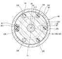
- the third cylinder protruding portion 231 has holes 235 and 236 instead of the grooves 233 and 234 shown in the first embodiment.
- the hole portions 235 and 236 are formed so as to connect the end surface on the valve seat 14 side and the end surface on the opposite side of the valve seat 14 on the radially inner side of the third tube portion screw portion 232 of the third tube portion projecting portion 231.
- five hole portions 235 are formed in the circumferential direction of the third cylindrical portion projecting portion 231 so as to be circular when viewed from the direction of the axis Ax1.
- One hole 236 is formed so as to have an oval shape along the arc when viewed from the direction of the axis Ax1.
- the hole 236 is formed larger than the hole 235.
- the holes 235 and 236 are formed so as to be substantially equidistant in the circumferential direction of the third cylindrical protrusion 231. That is, the holes 235 and 236 are formed at an interval of about 60 degrees in the circumferential direction of the third cylindrical protrusion 231.
- the holes 235 and 236 connect the space on the opposite side to the valve seat 14 of the third cylindrical protrusion 231 and the coil housing chamber 101.
- the bobbin extending portion 811 is inserted in the hole portion 236.
- the manufacturing method of the fuel injection device is different from the first embodiment in the coil assembly process and the molding process as follows.
- the coil 80 is assembled to the outside of the housing 20 so that the bobbin extending portion 811 is inserted into the hole 236.
- the heated thermoplastic resin is filled into the coil housing chamber 101 via the hole 235 and the outer wall of the third cylindrical portion 23 is covered with the heated thermoplastic resin to form the mold portion 83.
- the third cylindrical projecting portion 231 includes the coil housing chamber 101 that houses the coil 80 between the end surface on the valve seat 14 side, the inner wall of the yoke 90, and the outer wall of the housing 20. It has holes 235 and 236 that are formed and connect the end surface on the valve seat 14 side and the end surface on the opposite side of the valve seat 14 on the radially inner side of the third cylindrical thread portion 232. The periphery of the coil 80 in the coil housing chamber 101 is covered with resin.
- the hole portions 235 and 236 are formed on the inner side in the radial direction of the third tube portion screw portion 232 of the third tube portion protruding portion 231. Therefore, the third tube portion threaded portion 232 is formed so as to be continuous over the entire circumferential range of the third tube portion protruding portion 231 without being partly cut away in the circumferential direction as in the first embodiment. Has been. Therefore, the axial force F ⁇ b> 1 in the direction in which the first tube portion 21 and the third tube portion 23 approach each other can be made uniform over the entire circumferential range of the third tube portion screw portion 232.
- the hole 235 is formed in a circular shape, and the hole 236 is formed in an oval shape. Therefore, the holes 235 and 236 can be easily formed by, for example, a drill.
- FIG. 6 A part of the fuel injection device according to the third embodiment of the present disclosure is illustrated in FIG. 6.
- the third embodiment is different from the second embodiment in the configuration of the third cylindrical protrusion 231.
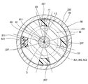
- the third cylinder protruding portion 231 has a hole 237 instead of the holes 235 and 236 shown in the second embodiment.
- the hole 237 is formed so as to connect the end surface on the valve seat 14 side and the end surface on the opposite side of the valve seat 14 on the radially inner side of the third tube portion screw portion 232 of the third tube portion projecting portion 231.
- four hole portions 237 are formed in the circumferential direction of the third tubular portion projecting portion 231 so as to have a shape obtained by removing the sector shape with the radius r2 from the sector shape with the radius r1 when viewed from the direction of the axis Ax1.
- r1 is smaller than the radius of the 3rd cylinder part protrusion part 231, and larger than r2 (refer FIG. 6).
- r2 is equivalent to half of the outer diameter of the cylindrical third tube portion 23.
- the hole portions 237 are formed so as to be substantially equidistant in the circumferential direction of the third cylinder protruding portion 231. That is, the hole portions 237 are formed at intervals of about 90 degrees in the circumferential direction of the third cylindrical portion protruding portion 231.
- the hole 237 connects the space on the opposite side of the valve seat 14 of the third cylindrical projecting portion 231 and the coil housing chamber 101.
- the bobbin extending portion 811 is inserted into one of the four hole portions 237.
- the manufacturing method of the fuel injection device is different from the second embodiment in the coil assembly process and the molding process as follows.
- the coil 80 is assembled to the outside of the housing 20 so that the bobbin extending portion 811 is inserted into the hole portion 237.
- the heated thermoplastic resin is filled into the coil housing chamber 101 via the hole 237 and the outer wall of the third cylindrical portion 23 is covered with the heated thermoplastic resin to form the mold portion 83.
- the third cylindrical projecting portion 231 includes the coil housing chamber 101 that houses the coil 80 between the end surface on the valve seat 14 side, the inner wall of the yoke 90, and the outer wall of the housing 20.
- a hole portion 237 is formed to connect the end surface on the valve seat 14 side and the end surface on the opposite side of the valve seat 14 on the radially inner side of the third tube portion screw portion 232.
- the periphery of the coil 80 in the coil housing chamber 101 is covered with resin.
- the hole portion 237 is formed on the inner side in the radial direction of the third cylindrical portion screw portion 232 of the third cylindrical portion protruding portion 231. Therefore, the third tube portion threaded portion 232 is formed so as to be continuous over the entire circumferential range of the third tube portion protruding portion 231 without being partly cut away in the circumferential direction as in the first embodiment. Has been. Therefore, as in the second embodiment, the axial force F1 in the direction in which the first tube portion 21 and the third tube portion 23 approach each other is made uniform over the entire circumferential range of the third tube portion screw portion 232. Can do.
- the four hole portions 237 have the same shape and are formed at equal intervals in the circumferential direction of the third tubular portion protruding portion 231. Therefore, it is possible to improve the balance in the circumferential direction of the third cylindrical projecting portion 231 of the magnetic circuit formed in the yoke 90 when the coil 80 is energized.
- FIG. 7 shows a part of the fuel injection device according to the fourth embodiment of the present disclosure.
- the fourth embodiment is particularly different from the third embodiment in the configuration of the first tube portion 21, the third tube portion 23, and the yoke 90.
- the first tube portion 21 has a first tube portion protruding portion 212 that protrudes annularly from the outer wall to the radially outer side.
- a first tube portion screw portion 213 is formed on the radially outer surface of the first tube portion protruding portion 212.
- 3rd cylinder part protrusion part 231 does not have the 3rd cylinder part screw part 232 shown in 3rd Embodiment.
- the third tubular portion projecting portion 231 has a third tubular portion locking surface 238 on the outer edge portion of the end surface opposite to the valve seat 14.
- the hole portion 237 is formed on the inner side in the radial direction of the third tube portion locking surface 238.
- the yoke 90 has a yoke upper protruding portion 93 that protrudes in an annular shape radially inward from an inner wall in the axial direction. On the surface of the yoke upper protrusion 93 on the valve seat 14 side, a yoke upper locking surface 931 facing the third tube portion locking surface 238 is formed.
- the yoke 90 has a yoke lower thread portion 94 that is formed on the inner wall of the end portion on the valve seat 14 side and can be screwed into the first tube portion thread portion 213.
- the yoke 90 has a yoke lower screw portion 94 screwed into the first tube portion screw portion 213 so that the yoke upper engagement surface 931 and the third tube portion engagement surface 238 are in contact with each other.
- the first tube portion 21 and the third tube portion 23 are in a state in which an axial force F1 that is a force along the axis Ax1 in a direction in which the first tube portion 21 and the third tube portion 23 approach each other is generated. ing. Therefore, a force in a direction contracting in the direction of the axis Ax1 from the first cylinder portion 21 and the third cylinder portion 23 acts on the second cylinder portion 22 forming the magnetic aperture portion 221.
- the yoke 90 has a yoke upper locking surface 931 locked by the third tube portion locking surface 238, and relative movement of the housing 20 toward the valve seat 14 is restricted.
- the manufacturing method of the fuel injection device is different from the third embodiment in the yoke assembling process and the yoke welding process as follows.
- the third cylinder portion is engaged so that the first cylinder portion 21 and the third cylinder portion 23 are in a state where an axial force F1 of a predetermined magnitude is generated in a direction in which the first cylinder portion 21 and the third cylinder portion 23 approach each other.
- the yoke upper locking surface 931 is brought into contact with the stop surface 238, the yoke lower screw portion 94 is screwed into the first tube portion screw portion 213, and the yoke 90 is assembled to the housing 20.
- connection part c6 between the first cylindrical protrusion 212 and the yoke 90 is welded.
- the valve seat 14 side portion of the first tube portion protruding portion 212 is welded to the valve seat 14 side portion and the yoke lower screw portion 94 of the yoke 90 is welded to the valve seat 14 side portion. Therefore, “the yoke 90 extends in the axial direction during welding and the axial force F1 decreases” can be suppressed.
- the first tube portion 21 has the first tube portion screw portion 213.
- the third cylinder part 23 has a third cylinder part locking surface 238.
- the yoke 90 is screwed to the yoke upper locking surface 931 that is locked to the third cylindrical portion locking surface 238 and the relative movement of the housing 20 to the valve seat 14 side is restricted, and to the first cylindrical portion screw portion 213.
- a yoke lower thread portion 94 is provided.
- the 1st cylinder part 21 and the yoke 90 are being fixed so that relative rotation is impossible. Therefore, “decrease in axial force F1 due to relative rotation between the first tube portion 21 and the yoke 90” can be suppressed.
- the third cylindrical portion 23 projects annularly outwardly from the outer wall in the radial direction on the side opposite to the valve seat 14 with respect to the coil 80, and the third cylindrical portion locking surface on the end surface opposite to the valve seat 14. It has the 3rd cylinder part projection part 231 in which 238 is formed.
- the third tubular portion projecting portion 231 forms a coil housing chamber 101 that houses the coil 80 between the end face on the valve seat 14 side, the inner wall of the yoke 90, and the outer wall of the housing 20, and the third tubular portion locking surface 238. Is provided with a hole 237 that connects the end face on the valve seat 14 side and the end face on the opposite side of the valve seat 14.
- the periphery of the coil 80 in the coil housing chamber 101 is covered with resin.
- the hole portion 237 is formed on the radially inner side of the third tube portion locking surface 238 of the third tube portion protruding portion 231. Therefore, the third cylindrical portion locking surface 238 is formed so as to be continuous over the entire circumferential range of the third cylindrical portion projecting portion 231 without being partly cut away in the circumferential direction. Therefore, the axial force F ⁇ b> 1 in the direction in which the first tube portion 21 and the third tube portion 23 approach each other can be made uniform over the entire circumferential range of the third tube portion locking surface 238.
- FIG. 8 A part of the fuel injection device according to the fifth embodiment of the present disclosure is illustrated in FIG. 8.
- the fifth embodiment is different from the fourth embodiment particularly in the configuration of the first tube portion 21 and the yoke 90.
- a first tube portion locking surface 211 is formed on the outer wall of the first tube portion 21 of the housing 20 as in the first embodiment.
- the yoke 90 includes a first yoke 901 and a second yoke 902.
- the first yoke 901 and the second yoke 902 are formed in a cylindrical shape and are coaxial.
- the first yoke 901 has a yoke lower locking surface 911 that is locked to the first tube portion locking surface 211 to restrict relative movement of the housing 20 to the opposite side of the valve seat 14. .
- the second yoke 902 is provided on the side opposite to the valve seat 14 with respect to the first yoke 901, and is locked to the third tube portion locking surface 238 of the third tube portion protruding portion 231, so that the valve with respect to the housing 20 is provided.
- a yoke upper locking surface 931 that restricts relative movement toward the seat 14 is provided.
- the first yoke 901 has a first yoke threaded portion 903 on the inner wall at the end opposite to the valve seat 14.
- the second yoke 902 has a second yoke screw portion 904 that can be screwed into the first yoke screw portion 903 on the outer wall of the end portion on the valve seat 14 side.
- the yoke lower locking surface 911 and the first tube portion locking surface 211 are in contact with each other, and the yoke upper locking surface 931 and the third tube portion locking surface 238 are in contact with each other.
- the yoke screw portion 903 and the second yoke screw portion 904 are screwed together.
- the first cylindrical portion 21 and the third cylindrical portion 23 are in a state where an axial force F1 that is a force along the axis Ax1 in a direction in which the first cylindrical portion 21 and the third cylindrical portion 23 approach each other is generated. Therefore, a force in a direction contracting in the direction of the axis Ax1 from the first cylinder portion 21 and the third cylinder portion 23 acts on the second cylinder portion 22 forming the magnetic aperture portion 221.
- the yoke 90 has a yoke lower locking surface 911 locked to the first tube portion locking surface 211, and relative movement of the housing 20 to the opposite side of the valve seat 14 is restricted.
- the yoke 90 has a yoke upper locking surface 931 locked by the third tube portion locking surface 238, and relative movement of the housing 20 toward the valve seat 14 is restricted.
- the manufacturing method of the fuel injection device is different from the fourth embodiment in the yoke assembly process as follows. Moreover, in this embodiment, the manufacturing method of a fuel injection apparatus does not include the yoke welding process shown in 4th Embodiment.
- the first cylinder part engagement is such that the first cylinder part 21 and the third cylinder part 23 are in a state where an axial force F1 of a predetermined magnitude is generated in a direction in which the first cylinder part 21 and the third cylinder part 23 approach each other.
- the yoke lower locking surface 911 of the first yoke 901 is brought into contact with the stop surface 211
- the yoke upper locking surface 931 of the second yoke 902 is brought into contact with the third tube portion locking surface 238, and the first yoke screw portion.
- 903 and the second yoke threaded portion 904 are screwed together, and the yoke 90 is assembled to the housing 20.
- the first tube portion 21 has the first tube portion locking surface 211.
- the third cylinder part 23 has a third cylinder part locking surface 238.
- the yoke 90 is locked to the first tube portion locking surface 211 so that the relative movement of the housing 20 to the side opposite to the valve seat 14 is restricted, and the third tube portion.
- the upper locking surface 931 on the yoke is restricted by being locked to the locking surface 238 so that the relative movement of the housing 20 toward the valve seat 14 is restricted.
- the yoke 90 includes the first yoke 901 on which the yoke lower locking surface 911 is formed and the second yoke 902 on which the yoke upper locking surface 931 is formed.
- the first yoke 901 has a first yoke threaded portion 903 on the inner wall.
- the second yoke 902 has a second yoke screw portion 904 that is screwed to the first yoke screw portion 903 on the outer wall.
- FIG. 9 shows a part of the fuel injection device according to the sixth embodiment of the present disclosure.
- the sixth embodiment is different from the fifth embodiment particularly in the configuration of the yoke 90.
- the yoke 90 is formed in a cylindrical shape and has a yoke upper caulking portion 95 that protrudes annularly radially inward from an inner wall in the axial direction.
- a yoke upper locking surface 931 facing the third tube portion locking surface 238 is formed on the surface of the yoke upper caulking portion 95 on the valve seat 14 side.
- the yoke 90 is disposed on the yoke so that the yoke lower locking surface 911 and the first tube portion locking surface 211 are in contact with each other, and the yoke upper locking surface 931 and the third tube portion locking surface 238 are in contact with each other.
- the caulking portion 95 is caulked to the third tube portion protruding portion 231.
- the first tube portion 21 and the third tube portion 23 are in a state in which an axial force F1 that is a force along the axis Ax1 in a direction in which the first tube portion 21 and the third tube portion 23 approach each other is generated. ing. Therefore, a force in a direction contracting in the direction of the axis Ax1 from the first cylinder portion 21 and the third cylinder portion 23 acts on the second cylinder portion 22 forming the magnetic aperture portion 221.
- the yoke 90 has a yoke lower locking surface 911 locked to the first tube portion locking surface 211, and relative movement of the housing 20 to the opposite side of the valve seat 14 is restricted.
- the yoke 90 has a yoke upper locking surface 931 locked by the third tube portion locking surface 238, and relative movement of the housing 20 toward the valve seat 14 is restricted.
- the manufacturing method of the fuel injection device is different from the fifth embodiment in the yoke assembling process as follows.
- the first cylinder part engagement is such that the first cylinder part 21 and the third cylinder part 23 are in a state where an axial force F1 of a predetermined magnitude is generated in a direction in which the first cylinder part 21 and the third cylinder part 23 approach each other.
- the yoke lower locking surface 911 is brought into contact with the stop surface 211 and, for example, a jig is pressed from outside in the radial direction of the yoke 90, so that the yoke upper locking surface 931 comes into contact with the third tube portion locking surface 238.
- a caulking portion 95 is formed, and the yoke 90 is caulked to the third cylindrical portion protruding portion 231.
- the first tube portion 21 has the first tube portion locking surface 211.
- the third cylinder part 23 has a third cylinder part locking surface 238.
- the yoke 90 is locked to the first tube portion locking surface 211 so that the relative movement of the housing 20 to the side opposite to the valve seat 14 is restricted, and the third tube portion.
- the upper locking surface 931 on the yoke is restricted by being locked to the locking surface 238 so that the relative movement of the housing 20 toward the valve seat 14 is restricted.
- the yoke 90 is assembled to the housing 20 by being caulked by the third cylindrical projecting portion 231. Therefore, the yoke 90 can be assembled to the housing 20 relatively easily.
- FIG. 10 shows a part of the fuel injection device according to the seventh embodiment of the present disclosure.
- the seventh embodiment is different from the fifth embodiment particularly in the configuration of the yoke 90.
- the first tube portion 21 has a first tube portion locking surface 211.
- the yoke 90 is formed in a cylindrical shape, and has a yoke lower caulking portion 96 that protrudes annularly radially inward from the end portion on the valve seat 14 side.
- a yoke lower locking surface 911 facing the first tube portion locking surface 211 of the first tube portion 21 is formed on the surface of the yoke lower caulking portion 96 on the opposite side to the valve seat 14.
- the yoke 90 is arranged so that the yoke upper locking surface 931 and the third tube portion locking surface 238 are in contact with each other, and the yoke lower locking surface 911 and the first tube portion locking surface 211 are in contact with each other.
- the caulking portion 96 is caulked to the first tube portion 21.
- the first tube portion 21 and the third tube portion 23 are in a state in which an axial force F1 that is a force along the axis Ax1 in a direction in which the first tube portion 21 and the third tube portion 23 approach each other is generated. ing. Therefore, a force in a direction contracting in the direction of the axis Ax1 from the first cylinder portion 21 and the third cylinder portion 23 acts on the second cylinder portion 22 forming the magnetic aperture portion 221.
- the yoke 90 has a yoke lower locking surface 911 locked to the first tube portion locking surface 211, and relative movement of the housing 20 to the opposite side of the valve seat 14 is restricted.
- the yoke 90 has a yoke upper locking surface 931 locked by the third tube portion locking surface 238, and relative movement of the housing 20 toward the valve seat 14 is restricted.
- the manufacturing method of the fuel injection device is different from the fifth embodiment in the yoke assembling process as follows.
- the third cylinder portion is engaged so that the first cylinder portion 21 and the third cylinder portion 23 are in a state where an axial force F1 of a predetermined magnitude is generated in a direction in which the first cylinder portion 21 and the third cylinder portion 23 approach each other.
- the yoke upper locking surface 931 is brought into contact with the stop surface 238 and, for example, a jig is pressed from the radially outer end of the yoke 90 on the valve seat 14 side, and the yoke lower locking surface 911 is locked to the first tube portion.
- a yoke lower caulking portion 96 is formed so as to contact the surface 211, and the yoke 90 is caulked to the first tube portion 21.
- the first tube portion 21 has the first tube portion locking surface 211.
- the third cylinder part 23 has a third cylinder part locking surface 238.
- the yoke 90 is locked to the first tube portion locking surface 211 so that the relative movement of the housing 20 to the side opposite to the valve seat 14 is restricted, and the third tube portion.
- the upper locking surface 931 on the yoke is restricted by being locked to the locking surface 238 so that the relative movement of the housing 20 toward the valve seat 14 is restricted.
- the yoke 90 is assembled to the housing 20 by being caulked to the first cylindrical portion 21. Therefore, the yoke 90 can be assembled to the housing 20 relatively easily.
- FIG. 11 shows a part of the fuel injection device according to the eighth embodiment of the present disclosure.
- the eighth embodiment is particularly different from the first embodiment in the configuration of the first tube portion 21, the second tube portion 22, the third tube portion 23, and the yoke 90.
- the first tube portion 21 and the second tube portion 22 are integrally formed of a magnetic material such as ferritic stainless steel, for example. That is, the 1st cylinder part 21 and the 2nd cylinder part 22 are integrally formed with the same material.
- the 2nd cylinder part 22 has the magnetic aperture part 221 in a part of axial direction.
- the magnetic aperture portion 221 is thinner than other portions of the second cylinder portion 22 in the axial direction.
- the end of the second tube portion 22 on the third tube portion 23 side is welded to the third tube portion 23.
- the third cylindrical portion 23 is formed separately from the fixed core body 51 of the fixed core 50 by a separate member.
- the fixed core main body 51 is provided inside the third cylindrical portion 23 by press-fitting, for example.
- the third cylinder thread portion 232 is formed over the entire axial range of the third cylinder protrusion 231.
- a yoke upper screw portion 92 that can be screwed into the third tube portion screw portion 232 is formed on the inner wall in the axial direction of the yoke 90.
- the manufacturing method of the fuel injection device is different from the first embodiment in the housing welding process as follows. Further, in the present embodiment, the method for manufacturing the fuel injection device includes the fixed core press-fitting step and does not include the yoke welding step shown in the first embodiment.
- the fixed core body 51 is press-fitted inside the third cylindrical portion 23.
- the second cylindrical portion 22 and the third cylindrical portion 23 are welded in a state where the needle 30 and the movable core 40 are accommodated inside the housing 20.
- the coil 80 is assembled to the outside of the housing 20 so that the bobbin extending portion 811 is positioned in the groove portion 234.
- the first cylinder part engagement is such that the first cylinder part 21 and the third cylinder part 23 are in a state where an axial force F1 of a predetermined magnitude is generated in a direction in which the first cylinder part 21 and the third cylinder part 23 approach each other.
- the yoke lower locking surface 911 is brought into contact with the stop surface 211, the yoke upper screw portion 92 is screwed into the third tube portion screw portion 232, and the yoke 90 is assembled to the housing 20.
- the second tube portion 22 is formed integrally with the first tube portion 21. Therefore, the number of members and assembly man-hours can be reduced. Also in the present embodiment, the yoke 90 is provided so that the first cylindrical portion 21 and the third cylindrical portion 23 generate an axial force F1 in a direction in which the first cylindrical portion 21 and the third cylindrical portion 23 approach each other. Therefore, a force in a direction contracting in the direction of the axis Ax1 from the first cylinder portion 21 and the third cylinder portion 23 acts on the second cylinder portion 22 forming the magnetic aperture portion 221.
- the second cylindrical portion 22 may be formed integrally with the third cylindrical portion 23 if the magnetic throttle portion 221 is formed by, for example, thinning. Good. Further, the second cylinder part 22 may be formed integrally with the first cylinder part 21 and the third cylinder part 23.
- the first yoke screw portion 903 is formed on the inner wall of the first yoke 901, and the second yoke screw portion 904 is formed on the outer wall of the second yoke 902.
- the first yoke screw portion 903 is formed on the outer wall of the first yoke 901
- the second yoke screw portion 904 is formed on the inner wall of the second yoke 902. Good.
- the housing 20 may be formed of a metal other than stainless steel, such as iron or aluminum.
- the example in which the nozzle 10 and the first tube portion 21 are formed separately has been shown.
- the nozzle 10 and the 1st cylinder part 21 are good also as being integrally formed.
- the gap forming member 60 may not be provided. In this case, no axial gap is formed between the contact surface 34 of the flange 33 and the movable core 40 when the valve is closed. In other embodiments of the present disclosure, the movable core 40 may be formed integrally with the needle 30. In another embodiment of the present disclosure, at least one of the spring seat portion 291, the fixing portion 292, the tubular portion 293, and the spring 73 may not be provided.
- the screw coupling member 26 may be screwed into the fuel pipe 6 so that the cylinder member 25 and the fuel pipe 6 are in a tightly coupled state.
- cylindrical member 25 and the screw coupling member 26 may not be provided.
- the fuel injection device may be attached to the engine 2 so as to be pressed against the step surface of the attachment hole 5 with a predetermined force, for example, by a fuel rail distribution pipe or the like. .
- the present disclosure is not limited to a direct injection type gasoline engine, and may be applied to, for example, a port injection type gasoline engine or a diesel engine.
Landscapes
- Engineering & Computer Science (AREA)
- Chemical & Material Sciences (AREA)
- Combustion & Propulsion (AREA)
- Mechanical Engineering (AREA)
- General Engineering & Computer Science (AREA)
- Physics & Mathematics (AREA)
- Electromagnetism (AREA)
- Fuel-Injection Apparatus (AREA)
Abstract
ハウジング(20)は、一端がノズル(10)に接続される第1筒部(21)、一端が第1筒部(21)の他端に接続され軸方向の少なくとも一部に磁気絞り部(221)を形成する第2筒部(22)、一端が第2筒部(22)の他端に接続される第3筒部(23)、ならびに、噴孔(13)に連通するよう第1筒部(21)、第2筒部(22)および第3筒部(23)の内側に形成され噴孔(13)に燃料を導く燃料通路(100)を有している。ヨーク(90)は、筒状に形成され、一端側が第1筒部(21)に接続し、他端側が第3筒部(23)に接続し、第1筒部(21)および第3筒部(23)に第1筒部(21)と第3筒部(23)とが互いに近付く方向の軸力が生じた状態となるようハウジング(20)の径方向外側に設けられている。
Description
本出願は、2015年10月2日に出願された日本特許出願番号2015-196824号に基づくもので、ここにその記載内容を援用する。
本開示は、内燃機関に燃料を噴射供給する燃料噴射装置に関する。
近年、高圧の燃料を噴射可能な燃料噴射装置のニーズが高まっている。そのため、燃料噴射装置の使用時、装置内の燃料通路内の燃料の圧力は増大する傾向にある。特許文献1に記載された燃料噴射装置では、ハウジングの一部を構成するノズルホルダが、固定コアに圧入されている。固定コアとノズルホルダとは、圧入位置で溶接により接合されている。また、ノズルホルダには薄肉部を有する磁気絞り部が形成されており、当該磁気絞り部が固定コアに圧入され、固定コアに溶接により接合されている。
特許文献1の燃料噴射装置では、装置内の燃料通路内の燃料の圧力が高くなると、固定コアとノズルホルダとの溶接箇所または薄肉の磁気絞り部に、固定コアとノズルホルダとが軸方向に離れる方向の力が作用する。装置内の燃料通路内の燃料の圧力が過大になると、固定コアとノズルホルダとの溶接箇所または磁気絞り部に応力が集中し、当該溶接箇所または磁気絞り部が破断するおそれがある。溶接箇所または磁気絞り部が破断すると、燃料通路内の燃料が外部に漏れ出すおそれがある。よって、特許文献1の燃料噴射装置では、構造上、高圧の燃料を噴射するのが困難である。
また、特許文献1の燃料噴射装置では、装置内の燃料通路内の燃料の圧力が過大になると、固定コアに対する磁気絞り部の位置が軸方向にずれ、固定コアと可動コアとの間に生じる磁気吸引力の大きさが変動するおそれがある。これにより、燃料の噴射精度が低下するおそれがある。
本開示は、燃料の漏れを抑制しつつ、高圧の燃料を高精度に噴射可能な燃料噴射装置を提供することを目的とする。
本開示の燃料噴射装置は、ノズルとハウジングとニードルと可動コアと固定コアと弁座側付勢部材とヨークとコイルとを備えている。ノズルは、燃料が噴射される噴孔、および、噴孔の周囲に環状に形成される弁座を有している。
ハウジングは、一端がノズルに接続される第1筒部、一端が第1筒部の他端に接続され軸方向の少なくとも一部に磁気絞り部を形成する第2筒部、一端が第2筒部の他端に接続される第3筒部、ならびに、噴孔に連通するよう第1筒部、第2筒部および第3筒部の内側に形成され噴孔に燃料を導く燃料通路を有している。
ニードルは、棒状のニードル本体、および、弁座に当接可能なようニードル本体の一端に環状に形成されるシール部を有し、シール部が弁座から離間または弁座に当接すると噴孔を開閉する。可動コアは、ニードルとともにハウジング内を往復移動可能に設けられている。固定コアは、第2筒部および第3筒部の内側の可動コアに対し弁座とは反対側に設けられている。弁座側付勢部材は、ニードルおよび可動コアを弁座側に付勢可能である。
ヨークは、筒状に形成され、一端側が第1筒部に接続し、他端側が第3筒部に接続し、第1筒部および第3筒部に第1筒部と第3筒部とが互いに近付く方向の軸力が生じた状態となるようハウジングの径方向外側に設けられている。
コイルは、ハウジングとヨークとの間に設けられ、通電されると第1筒部、可動コア、固定コア、第3筒部およびヨークに磁気回路を形成し、可動コアを固定コア側に吸引しニードルを弁座とは反対側に移動させることが可能である。
本開示では、ヨークが、第1筒部および第3筒部に第1筒部と第3筒部とが互いに近付く方向の軸力が生じるよう設けられている。そのため、磁気絞り部を形成する第2筒部には、第1筒部と第3筒部とから軸方向に縮まる方向の力が作用している。これにより、燃料通路内の燃料の圧力が高くなっても、第2筒部と第1筒部との接続部、第2筒部と第3筒部との接続部、または、磁気絞り部に作用する「各部材が軸方向に離れる方向の力」を抑制することができる。したがって、第2筒部と第1筒部との接続部、第2筒部と第3筒部との接続部、または、磁気絞り部に応力が集中し破断するのを抑制することができる。よって、本開示では、燃料の漏れを抑制しつつ、高圧の燃料を噴射することができる。
また、本開示では、磁気絞り部を形成する第2筒部に、第1筒部と第3筒部とから軸方向に縮まる方向の力が作用しているため、燃料通路内の燃料の圧力が高くなっても、固定コアに対する磁気絞り部の位置が軸方向にずれるのを抑制することができる。そのため、固定コアと可動コアとの間に生じる磁気吸引力の大きさが変動するのを抑制することができる。これにより、燃料の噴射精度の低下を抑制することができる。
このように、本開示の燃料噴射装置では、燃料の漏れを抑制しつつ、高圧の燃料を高精度に噴射可能である。
本開示についての上記目的およびその他の目的、特徴や利点は、添付の図面を参照しながら下記の詳細な記述により、より明確になる。
図1は、本開示の第1実施形態による燃料噴射装置を示す断面図。
図2は、本開示の第1実施形態による燃料噴射装置の燃料入口部およびその近傍を示す断面図。
図3は、本開示の第1実施形態による燃料噴射装置のヨークおよびその近傍を示す断面図。
図4は、図3のIV-IV線断面図。
図5は、本開示の第2実施形態による燃料噴射装置の第3筒部突出部およびその近傍を示す断面図。
図6は、本開示の第3実施形態による燃料噴射装置の第3筒部突出部およびその近傍を示す断面図。
図7は、本開示の第4実施形態による燃料噴射装置のヨークおよびその近傍を示す断面図。
図8は、本開示の第5実施形態による燃料噴射装置のヨークおよびその近傍を示す断面図。
図9は、本開示の第6実施形態による燃料噴射装置のヨークおよびその近傍を示す断面図。
図10は、本開示の第7実施形態による燃料噴射装置のヨークおよびその近傍を示す断面図。
図11は、本開示の第8実施形態による燃料噴射装置のヨークおよびその近傍を示す断面図。
以下、本開示の複数の実施形態を図に基づいて説明する。なお、複数の実施形態において、実質的に同一の構成部位には同一の符号を付し、説明を省略する。
(第1実施形態)
本開示の第1実施形態による燃料噴射弁を図1に示す。燃料噴射装置1は、例えば内燃機関としての直噴式ガソリンエンジン(以下、「エンジン」)2に用いられ、燃料としてのガソリンをエンジン2に噴射供給する。
本開示の第1実施形態による燃料噴射弁を図1に示す。燃料噴射装置1は、例えば内燃機関としての直噴式ガソリンエンジン(以下、「エンジン」)2に用いられ、燃料としてのガソリンをエンジン2に噴射供給する。
燃料噴射装置1は、ノズル10、ハウジング20、ニードル30、可動コア40、固定コア50、隙間形成部材60、弁座側付勢部材としてのスプリング71、コイル80、ヨーク90、インレット部24、フィルタ241、筒部材25、ねじ結合部材26等を備えている。
ノズル10は、例えばマルテンサイト系ステンレス等の硬度が比較的高い材料により形成されている。ノズル10は、所定の硬度を有するよう焼入れ処理が施されている。ノズル10は、ノズル筒部11、および、ノズル筒部11の一端を塞ぐノズル底部12を有している。ノズル底部12には、ノズル筒部11側の面とノズル筒部11とは反対側の面とを接続する噴孔13が複数形成されている。また、ノズル底部12のノズル筒部11側の面には、噴孔13の周囲に環状の弁座14が形成されている。ハウジング20は、第1筒部21、第2筒部22、第3筒部23等を有している。
第1筒部21、第2筒部22および第3筒部23は、いずれも略円筒状に形成されている。第1筒部21、第2筒部22および第3筒部23は、第1筒部21、第2筒部22、第3筒部23の順に同軸(軸Ax1)となるよう配置され、互いに接続している。第2筒部22と第1筒部21および第3筒部23とは、例えば溶接により接続されている。図1において、第2筒部22と第1筒部21との接続部をc1で示し、第2筒部22と第3筒部23との接続部をc2で示す。接続部c1には、溶接により第2筒部22の一部と第1筒部21の一部とが溶融し冷え固まった溶融部w1が形成されている。また、接続部c2には、溶接により第2筒部22の一部と第3筒部23の一部とが溶融し冷え固まった溶融部w2が形成されている。
第1筒部21および第3筒部23は、例えばフェライト系ステンレス等の磁性材料により形成され、磁気安定化処理が施されている。第1筒部21および第3筒部23は、硬度が比較的低い。一方、第2筒部22は、例えばオーステナイト系ステンレス等の非磁性材料により形成されている。つまり、第2筒部22は、軸方向の全てにおいて磁気絞り部221を形成している。第2筒部22の硬度は、第1筒部21および第3筒部23の硬度よりも高い。
第1筒部21の第2筒部22とは反対側の端部の内側には、ノズル筒部11のノズル底部12とは反対側の端部が接合されている。第1筒部21とノズル10とは、例えば溶接により接続されている。図1において、第1筒部21とノズル10との接続部をc3で示す。接続部c3には、溶接により第1筒部21の一部とノズル10の一部とが溶融し冷え固まった溶融部w3が形成されている。
インレット部24は、例えばステンレス等の金属により筒状に形成されている。インレット部24は、一端が第3筒部23の第2筒部22とは反対側の端部の径方向内側に接続するよう設けられている。本実施形態では、インレット部24と第3筒部23とは、同一の材料により一体に形成されている。図1では、インレット部24と第3筒部23との境界を二点鎖線で示している。
筒部材25は、インレット部24の第3筒部23とは反対側に設けられている。筒部材25は、例えばステンレス等の金属により筒状に形成されている。筒部材25は、一端がインレット部24の第3筒部23とは反対側の端部の径方向外側に接続するよう設けられている。本実施形態では、筒部材25とインレット部24とは、例えば溶接により接続されている。図1において、筒部材25とインレット部24との接続部をc4で示す。接続部c4には、溶接により筒部材25の一部とインレット部24の一部とが溶融し冷え固まった溶融部w4が形成されている。筒部材25のインレット部24とは反対側の端部の外壁にはねじ部251が形成されている。
筒部材25のインレット部24とは反対側の端部には、外部からの燃料が流れる燃料配管6が接続される。燃料配管6の筒部材25側の端部には、径方向外側へ環状に突出する突出部7が形成されている。突出部7の筒部材25とは反対側の端面には、係止面8が形成されている。
ねじ結合部材26は、例えばステンレス等の金属により筒状に形成されている。ねじ結合部材26の一方の端部の内壁には、ねじ部251に螺合可能なねじ部261が形成されている。ねじ結合部材26の他方の端部には、径方向内側へ環状に突出する突出部262が形成されている。突出部262のねじ部261側の端面には、係止面263が形成されている。
ねじ結合部材26は、筒部材25のインレット部24とは反対側の端面と燃料配管6の筒部材25側の端面とが当接し、係止面263と係止面8とが当接した状態となるよう、ねじ部261がねじ部251に螺合される。このとき、筒部材25および燃料配管6には、筒部材25と燃料配管6とが互いに近付く方向の軸力が作用した状態となる。これにより、筒部材25のインレット部24とは反対側の端面と燃料配管6の筒部材25側の端面とが互いに密着した結合状態となる。
ハウジング20およびノズル筒部11の内側には、燃料通路100が形成されている。燃料通路100は、噴孔13に連通している。これにより、燃料通路100には、燃料供給源等、外部からの燃料が燃料配管6、筒部材25およびインレット部24を経由して流入する。燃料通路100は、燃料を噴孔13に導く。インレット部24および筒部材25は、「燃料入口部」に対応している。フィルタ241は、インレット部24の内側に設けられている。フィルタ241は、燃料通路100に流入する燃料中の異物を捕集する。
ニードル30は、例えばマルテンサイト系ステンレス等の硬度が比較的高い材料により形成されている。ニードル30は、所定の硬度を有するよう焼入れ処理が施されている。ニードル30の硬度は、ノズル10の硬度とほぼ同等に設定されている。ニードル30は、燃料通路100内をハウジング20の軸Ax1方向へ往復移動可能なようハウジング20内に収容されている。ニードル30は、ニードル本体31、シール部32、鍔部33等を有している。ニードル本体31は、棒状、より具体的には長い円柱状に形成されている。シール部32は、ニードル本体31の一端、すなわち、弁座14側の端部に形成され、弁座14に当接可能である。
鍔部33は、環状に形成され、ニードル本体31の他端、すなわち、弁座14とは反対側の端部の径方向外側に設けられている。本実施形態では、鍔部33は、ニードル本体31と同一の材料により一体に形成されている。
図1に示すように、ニードル本体31の一端の近傍には、大径部311が形成されている。ニードル本体31の一端側の外径は、他端側の外径より小さい。大径部311は、外径がニードル本体31の一端側の外径より大きく、ニードル本体31の他端側の外径と同等である。大径部311は、外壁がノズル10のノズル筒部11の内壁と摺動するよう形成されている。これにより、ニードル30は、弁座14側の端部の軸Ax1方向の往復移動が案内される。大径部311には、外壁の周方向の複数個所が面取りされるようにして面取り部312が形成されている。これにより、燃料は、面取り部312とノズル10のノズル筒部11の内壁との間を流通可能である。
ニードル本体31の他端には、ニードル本体31の軸Ax2に沿って延びる軸方向穴部313が形成されている。すなわち、ニードル本体31の他端は、中空筒状に形成されている。また、ニードル本体31には、軸方向穴部313の弁座14側の端部とニードル本体31の外側の空間とを接続するようニードル本体31の径方向に延びる径方向穴部314が形成されている。これにより、燃料通路100内の燃料は、軸方向穴部313および径方向穴部314を流通可能である。このように、ニードル本体31は、弁座14とは反対側の端面から軸Ax2方向に延び径方向穴部314を経由してニードル本体31の外側の空間に連通する軸方向穴部313を有している。
ニードル30は、シール部32が弁座14から離間(離座)または弁座14に当接(着座)することで噴孔13を開閉する。以下、適宜、ニードル30が弁座14から離間する方向を開弁方向といい、ニードル30が弁座14に当接する方向を閉弁方向という。
可動コア40は、可動コア本体41を有している。可動コア本体41は、例えばフェライト系ステンレス等の磁性材料により略円柱状に形成されている。可動コア本体41は、磁気安定化処理が施されている。可動コア本体41の硬度は比較的低く、ハウジング20の第1筒部21および第3筒部23の硬度と概ね同等である。
可動コア40は、軸穴部42、凹部44等を有している。軸穴部42は、可動コア本体41の軸Ax3に沿って延びるよう形成されている。本実施形態では、軸穴部42の内壁に、例えばNi-Pめっき等の硬質加工処理および摺動抵抗低減処理が施されている。凹部44は、可動コア本体41の弁座14側の面から弁座14とは反対側へ円形に凹むよう可動コア本体41の中央に形成されている。軸穴部42は、凹部44の底部に開口している。
可動コア40は、軸穴部42にニードル30のニードル本体31が挿通された状態でハウジング20内に収容されている。可動コア40の軸穴部42の内径は、ニードル30のニードル本体31の外径と同等、または、ニードル本体31の外径よりやや大きく設定されている。そのため、可動コア40は、軸穴部42の内壁がニードル30のニードル本体31の外壁に摺動しつつ、ニードル30に対し相対移動可能である。また、可動コア40は、ニードル30と同様、燃料通路100内をハウジング20の軸Ax1方向へ往復移動可能なようハウジング20内に収容されている。本実施形態では、可動コア本体41の弁座14とは反対側の面に、例えば硬質クロムめっき等の硬質加工処理および耐摩耗処理が施されている。
可動コア本体41の外径は、ハウジング20の第1筒部21および第2筒部22の内径より小さく設定されている。そのため、可動コア40が燃料通路100内を往復移動するとき、可動コア40の外壁と第1筒部21および第2筒部22の内壁とは摺動しない。
図3に示すように、ニードル30の鍔部33は、弁座14側の面が可動コア本体41の弁座14とは反対側の面に当接可能である。つまり、ニードル30は、可動コア本体41の弁座14とは反対側の面に当接可能な当接面34を有している。当接面34は、鍔部33の弁座14側の面に形成されている。可動コア40は、当接面34に当接または当接面34から離間可能なようニードル30に対し相対移動可能に設けられている。
図1に示すように、固定コア50は、ハウジング20の内側の可動コア40に対し弁座14とは反対側に設けられている。固定コア50は、固定コア本体51およびブッシュ52を有している。固定コア本体51は、例えばフェライト系ステンレス等の磁性材料により略円筒状に形成されている。固定コア本体51は、磁気安定化処理が施されている。固定コア本体51の硬度は比較的低く、可動コア本体41の硬度と概ね同等である。
本実施形態では、固定コア本体51と第3筒部23およびインレット部24とは、同一の材料により一体に形成されている。図1では、固定コア本体51と第3筒部23とインレット部24との境界を二点鎖線で示している。
ブッシュ52は、例えばマルテンサイト系ステンレス等の硬度が比較的高い材料により略円筒状に形成されている。ブッシュ52は、固定コア本体51の弁座14側の端部の内壁から径方向外側へ凹むよう形成された凹部511に設けられている。ここで、ブッシュ52の内径と固定コア本体51の内径とは概ね同等である。ブッシュ52の弁座14側の端面は、固定コア本体51の弁座14側の端面よりも弁座14側に位置している。そのため、可動コア本体41の弁座14とは反対側の面は、ブッシュ52の弁座14側の端面に当接可能である。
固定コア50は、シール部32が弁座14に当接した状態のニードル30の鍔部33が、ブッシュ52の内側に位置するよう設けられている。固定コア本体51の内側には、円筒状のアジャスティングパイプ53が圧入されている。隙間形成部材60は、例えば非磁性材料により形成されている。隙間形成部材60の硬度は、ニードル30およびブッシュ52の硬度とほぼ同等に設定されている。
隙間形成部材60は、ニードル30および可動コア40に対し弁座14とは反対側に設けられている。図3に示すように、隙間形成部材60は、板部61および延伸部62を有している。板部61は、略円板状に形成されている。板部61は、一方の端面が鍔部33およびニードル本体31に当接可能なようにニードル30に対し弁座14とは反対側に設けられている。
延伸部62は、板部61の一方の端面の外縁部から弁座14側へ円筒状に延びるよう板部61と一体に形成されている。すなわち、隙間形成部材60は、本実施形態では、有底円筒状に形成されている。隙間形成部材60は、延伸部62の内側にニードル30の鍔部33が位置するよう設けられている。また、延伸部62は、板部61とは反対側の端部が可動コア本体41の固定コア50側の面に当接可能である。
本実施形態では、延伸部62は、軸方向の長さが鍔部33の軸方向の長さより長い。そのため、隙間形成部材60は、板部61がニードル30に当接し、延伸部62が可動コア40に当接しているとき、鍔部33の弁座14側の面と可動コア40の弁座14とは反対側の面との間に軸Ax2方向の隙間である軸方向隙間CL1を形成可能である。
ここで、延伸部62の内径は、鍔部33の外径と同等、または、鍔部33の外径よりやや大きく設定されている。そのため、隙間形成部材60は、延伸部62の内壁、すなわち、鍔部33の外壁に対向する壁面が鍔部33の外壁と摺動可能で、ニードル30に対し相対移動可能である。また、板部61および延伸部62の外径は、固定コア50のブッシュ52の内径と同等、または、ブッシュ52の内径よりやや小さく設定されている。そのため、隙間形成部材60は、板部61および延伸部62の外壁、すなわち、ブッシュ52の内壁に対向する壁面が、ブッシュ52の内壁と摺動可能である。そのため、ニードル30は、固定コア50および隙間形成部材60により、鍔部33側の端部が軸方向に往復移動可能に案内される。
本実施形態では、ニードル30は、弁座14側の端部近傍がノズル10のノズル筒部11の内壁により往復移動可能に支持され、固定コア50側の部位が固定コア50および隙間形成部材60により往復移動可能に支持される。このように、ニードル30は、ハウジング20の軸Ax1方向の2箇所の部位により、軸方向の往復移動が案内される。
本実施形態では、延伸部62が筒状に形成されているため、延伸部62と可動コア40とが当接しているとき、鍔部33の当接面34と可動コア40と延伸部62の内壁との間に環状の空間である環状空間S1が形成される。
隙間形成部材60は、孔部611をさらに有している。孔部611は、板部61の一方の端面と他方の端面とを接続し、ニードル30の軸方向穴部313に連通可能である。これにより、燃料通路100内の隙間形成部材60の弁座14とは反対側の燃料は、孔部611、ニードル30の軸方向穴部313、径方向穴部314を経由して可動コア40の弁座14側に流通可能である。
スプリング71は、例えばコイルスプリングであり、隙間形成部材60に対し弁座14とは反対側に設けられている。スプリング71の一端は、隙間形成部材60の板部61の延伸部62とは反対側の端面に当接している。スプリング71の他端は、アジャスティングパイプ53に当接している。スプリング71は、隙間形成部材60を弁座14側に付勢する。スプリング71は、隙間形成部材60の板部61がニードル30に当接しているとき、隙間形成部材60を介してニードル30を弁座14側、すなわち、閉弁方向に付勢可能である。また、スプリング71は、隙間形成部材60の延伸部62が可動コア40に当接しているとき、隙間形成部材60を介して可動コア40を弁座14側に付勢可能である。すなわち、スプリング71は、隙間形成部材60を介してニードル30および可動コア40を弁座14側に付勢可能である。スプリング71の付勢力は、固定コア50に対するアジャスティングパイプ53の位置により調整される。
ヨーク90は、例えばフェライト系ステンレス等の磁性材料により筒状に形成され、磁気安定化処理が施されている。ヨーク90は、ハウジング20の特に第2筒部22の径方向外側に位置するよう設けられている。ヨーク90は、弁座14側の端部から径方向内側に環状に突出するヨーク下突出部91を有している。ヨーク下突出部91の弁座14とは反対側の端面には、ヨーク下係止面911が形成されている。ヨーク90は、軸方向の途中の内壁に形成されるヨーク上ねじ部92を有している。当該ヨーク上ねじ部92は、ヨーク90の周方向の全域にわたり形成されている。
ハウジング20の第1筒部21の外壁には、ヨーク下係止面911に対向する第1筒部係止面211が形成されている。第3筒部23は、外壁から径方向外側へ環状に突出する第3筒部突出部231を有している。第3筒部突出部231の径方向外側の面には、ヨーク上ねじ部92に螺合可能な第3筒部ねじ部232が形成されている。
ヨーク90は、ヨーク下係止面911と第1筒部係止面211とが当接した状態となるようヨーク上ねじ部92が第3筒部ねじ部232に螺合されている。ここで、第1筒部21および第3筒部23には、第1筒部21と第3筒部23とが互いに近付く方向の軸Ax1に沿う力である軸力F1が生じた状態となっている。そのため、磁気絞り部221を形成する第2筒部22には、第1筒部21と第3筒部23とから軸Ax1方向に縮まる方向の力が作用している。ヨーク90は、ヨーク下係止面911が第1筒部係止面211に係止され、ハウジング20に対する弁座14とは反対側への相対移動が規制されている。
また、本実施形態では、第3筒部突出部231の第3筒部ねじ部232に対し弁座14とは反対側の部位と、ヨーク90のヨーク上ねじ部92に対し弁座14とは反対側の部位とは、溶接により接続されている。図1において、第3筒部突出部231とヨーク90との接続部をc5で示す。接続部c5には、溶接により第3筒部突出部231の一部とヨーク90の一部とが溶融し冷え固まった溶融部w5が形成されている。これにより、第3筒部23とヨーク90とは、相対回転不能に固定されている。そのため、「第3筒部23とヨーク90とが相対回転することによる軸力F1の低下」を抑制することができる。第3筒部突出部231は、弁座14側の端面とヨーク90の内壁とハウジング20の外壁との間に、略円筒状のコイル収容室101を形成している。
図4に示すように、第3筒部突出部231には、溝部233、234が形成されている。溝部233、234は、第3筒部突出部231の外縁部から径方向内側へ切り欠かれるようにして形成されている。溝部233、234は、第3筒部突出部231の弁座14側の端面と弁座14とは反対側の端面とを接続するよう形成されている。本実施形態では、溝部233は、5つ形成されている。溝部234は1つ形成されている。溝部234は、溝部233と比べ大きく形成されている。溝部233、234は、第3筒部突出部231の周方向に略等間隔となるよう形成されている。すなわち、溝部233、234は、第3筒部突出部231の周方向に約60度間隔で形成されている。溝部233、234は、第3筒部突出部231の弁座14とは反対側の空間とコイル収容室101とを接続している。
図1、2に示すように、コイル80は、略円筒状に形成され、ハウジング20のうち特に第2筒部22と第1筒部21および第3筒部23との接続部c1、c2の径方向外側に位置するようコイル収容室101に設けられている。すなわち、コイル80は、ハウジング20とヨーク90との間に設けられている。
コイル80は、ボビン81および巻線82を有している。ボビン81は、例えば樹脂により筒状に形成されている。巻線82は、例えば銅線等からなりボビン81に巻回されている。また、ボビン81は、周方向の一部から軸と平行な方向へ延びるボビン延伸部811を有している。ボビン延伸部811の内側には、巻線82に接続する巻線端子821が設けられている。巻線端子821の巻線82とは反対側の端部は、ボビン延伸部811から外に飛び出した状態となっている。
コイル80は、ボビン延伸部811が第3筒部突出部231の溝部234に位置するよう設けられている。コイル収容室101には、熱可塑性の樹脂が充填されている。これにより、コイル収容室101内のコイル80の周囲は、樹脂で覆われている。また、溝部233、および、第3筒部23の第3筒部突出部231に対し弁座14とは反対側の外壁も、樹脂で覆われている。これにより、コイル収容室101、溝部233、第3筒部23の外壁にかけて、樹脂からなるモールド部83が形成されている。
モールド部83には、ケーブル27が接続するよう設けられている。ケーブル27は、ケーブル端子271および導線272を有している。ケーブル端子271は、モールド部83の内部において、巻線端子821と電気的に接続されている(図1参照)。
ケーブル27のモールド部83とは反対側の端部には、コネクタ28が接続するよう設けられている。コネクタ28には、コネクタ端子281がインサート成形されている。コネクタ端子281は、コネクタ28の内部において、導線272と電気的に接続されている(図2参照)。
コイル80は、コネクタ端子281、導線272、巻線端子821を経由して巻線82に電力が供給(通電)されると磁力を生じる。コイル80に磁力が生じると、第2筒部22の磁気絞り部221を避けるようにして、第1筒部21、可動コア40、固定コア50、第3筒部23、第3筒部突出部231およびヨーク90に磁気回路が形成される。これにより、固定コア本体51と可動コア本体41との間に磁気吸引力が発生し、可動コア40は、固定コア50側に吸引される。このとき、可動コア40は、軸方向隙間CL1を加速しつつ開弁方向に移動し、ニードル30の鍔部33の当接面34に衝突する。これにより、ニードル30が開弁方向に移動し、シール部32が弁座14から離間し、開弁する。その結果、噴孔13が開放される。このように、コイル80は、通電されると、可動コア40を固定コア50側に吸引し鍔部33に当接させ、ニードル30を弁座14とは反対側に移動させることが可能である。
上述のように、本実施形態では、閉弁状態において、隙間形成部材60が鍔部33と可動コア40との間に軸方向隙間CL1を形成するため、コイル80への通電時、可動コア40を軸方向隙間CL1で加速させて鍔部33に衝突させることができる。これにより、燃料通路100内の燃料の圧力が比較的高い場合でも、コイル80へ供給する電力を増大させることなく、開弁させることができる。
可動コア40は、磁気吸引力により固定コア50側(開弁方向)に吸引されると、可動コア本体41の固定コア50側の面がブッシュ52の弁座14側の端面に衝突する。これにより、可動コア40は、開弁方向への移動が規制される。本実施形態では、燃料噴射装置1は、ばね座部291、固定部292、筒部293およびスプリング73をさらに備えている。ばね座部291と固定部292とは、筒部293により互いに接続されている。ばね座部291、固定部292および筒部293は、例えばステンレス等の金属により一体に形成されている。ばね座部291は、環状に形成され、可動コア40とガイド部28との間においてニードル本体31の径方向外側に位置している。
固定部292は、筒状に形成され、可動コア40とばね座部291との間においてニードル本体31の径方向外側に位置している。固定部292は、内壁がニードル本体31の外壁に嵌合し、ニードル本体31に固定されている。
筒部293は、筒状に形成され、一端がばね座部291に接続し、他端が固定部292に接続している。これにより、ばね座部291は、可動コア40とガイド部28との間においてニードル本体31の径方向外側に固定されている。
スプリング73は、例えばコイルスプリングであり、一端がばね座部291に当接し、他端が可動コア40の凹部44の底部に当接するよう設けられている。スプリング73は、可動コア40を固定コア50側に付勢可能である。スプリング73の付勢力は、スプリング71の付勢力よりも小さい。
スプリング71が隙間形成部材60を弁座14側に付勢することで、隙間形成部材60の板部61とニードル30とが当接し、ニードル30は、シール部32が弁座14に押し付けられる。このとき、スプリング73が可動コア40を固定コア50側に付勢することで、隙間形成部材60の延伸部62と可動コア40とが互いに押し付けられるようにして当接する。この状態で、ニードル30の鍔部33の当接面34と可動コア40との間に軸方向隙間CL1が形成される。
可動コア40は、ニードル30の鍔部33と固定部292との間で軸方向に往復移動可能に設けられている。可動コア40の凹部44の底部は、固定部292の可動コア40側の端部に当接可能である。固定部292は、可動コア40に当接することで、ニードル30に対する可動コア40の弁座14側への相対移動を規制可能である。
また、本実施形態では、筒部293およびばね座部291とニードル本体31との間には、筒状の空間である筒状空間S2が形成されている。ここで、ニードル30の径方向穴部314は、筒状空間S2に連通している。よって、軸方向穴部313内の燃料は、径方向穴部314、筒状空間S2および流路部282を経由して弁座14側に流れることができる。
本実施形態では、可動コア40が固定コア50側に吸引されている状態でコイル80への通電を停止すると、ニードル30および可動コア40は、隙間形成部材60を介したスプリング71の付勢力により、弁座14側へ付勢される。これにより、ニードル30が閉弁方向に移動し、シール部32が弁座14に当接し、閉弁する。その結果、噴孔13が閉塞される。
シール部32が弁座14に当接した後、可動コア40は、慣性によりニードル30に対し弁座14側に相対移動する。このとき、固定部292は、可動コア40に当接することで、可動コア40の弁座14側への過度の移動を規制可能である。これにより、次の開弁時の応答性の低下を抑制可能である。また、スプリング73の付勢力により、可動コア40が固定部292に当接するときの衝撃を小さくでき、ニードル30が弁座14でバウンスすることによる二次開弁を抑制することができる。さらに、固定部292が可動コア40の弁座14側への移動を規制することにより、スプリング73の過度の圧縮を抑制でき、過度に圧縮されたスプリング73の復原力により可動コア40が開弁方向に付勢され再び鍔部33に衝突することによる二次開弁を抑制することができる。
筒部材25およびインレット部24から流入した燃料は、固定コア50、アジャスティングパイプ53、隙間形成部材60の孔部611、ニードル30の軸方向穴部313、径方向穴部314、筒状空間S2、第1筒部21とニードル30との間、ノズル10とニードル30との間、すなわち、燃料通路100を流通し、噴孔13に導かれる。
図1、2に示すように、本実施形態では、燃料噴射装置1は、ノズル10のノズル底部12がエンジン2の燃焼室3に露出するよう、エンジン2のエンジンヘッド4に形成された取付穴部5に取り付けられる。ここで、燃料噴射装置1は、ヨーク90のヨーク下突出部91のヨーク下係止面911とは反対側の面が、取付穴部5の段差面に押し付けられた状態となるよう取り付けられる。このとき、第1筒部21および第3筒部23に第1筒部21と第3筒部23とが互いに近付く方向の軸力が生じるものの、この軸力は、ヨーク90の第3筒部23との螺合により生じている軸力F1よりも小さい。
次に、本実施形態の燃料噴射装置1の製造方法について説明する。
本実施形態では、燃料噴射装置1の製造方法は、以下の工程を含む。
(ハウジング溶接工程)
ハウジング20の内側にニードル30および可動コア40等を収容した状態で、第2筒部22と第1筒部21および第3筒部23とを溶接する。
ハウジング20の内側にニードル30および可動コア40等を収容した状態で、第2筒部22と第1筒部21および第3筒部23とを溶接する。
(コイル組み付け工程)
ボビン延伸部811が溝部234に位置するようコイル80をハウジング20の外側に組み付ける。
ボビン延伸部811が溝部234に位置するようコイル80をハウジング20の外側に組み付ける。
(ヨーク組み付け工程)
第1筒部21および第3筒部23に第1筒部21と第3筒部23とが互いに近付く方向の所定の大きさの軸力F1が生じた状態となるよう、第1筒部係止面211にヨーク下係止面911を当接させ、第3筒部ねじ部232にヨーク上ねじ部92を螺合し、ヨーク90をハウジング20に組み付ける。
第1筒部21および第3筒部23に第1筒部21と第3筒部23とが互いに近付く方向の所定の大きさの軸力F1が生じた状態となるよう、第1筒部係止面211にヨーク下係止面911を当接させ、第3筒部ねじ部232にヨーク上ねじ部92を螺合し、ヨーク90をハウジング20に組み付ける。
(ヨーク溶接工程)
第3筒部突出部231とヨーク90との接続部c5を溶接する。なお、このとき、第3筒部突出部231の第3筒部ねじ部232に対し弁座14とは反対側の部位と、ヨーク90のヨーク上ねじ部92に対し弁座14とは反対側の部位とを溶接するため、「溶接時にヨーク90が軸方向に伸び、上記軸力F1が低下すること」を抑制できる。
第3筒部突出部231とヨーク90との接続部c5を溶接する。なお、このとき、第3筒部突出部231の第3筒部ねじ部232に対し弁座14とは反対側の部位と、ヨーク90のヨーク上ねじ部92に対し弁座14とは反対側の部位とを溶接するため、「溶接時にヨーク90が軸方向に伸び、上記軸力F1が低下すること」を抑制できる。
(モールド工程)
加熱した熱可塑性樹脂を、溝部233を経由してコイル収容室101に充填し、かつ、加熱した熱可塑性樹脂で第3筒部23の外壁を覆い、モールド部83を形成する。
加熱した熱可塑性樹脂を、溝部233を経由してコイル収容室101に充填し、かつ、加熱した熱可塑性樹脂で第3筒部23の外壁を覆い、モールド部83を形成する。
次に、本実施形態の燃料噴射装置1の作動について、説明する。
図1、3に示すように、コイル80に通電されていないときは、ニードル30のシール部32は弁座14に当接しており、隙間形成部材60の板部61はニードル30に当接し、延伸部62は可動コア40に当接している。このとき、鍔部33の当接面34と可動コア40との間には、軸方向隙間CL1が形成されている。
図1、3に示す状態のときにコイル80に通電すると、可動コア40は、固定コア50側に吸引され、隙間形成部材60を押し上げながら軸方向隙間CL1で加速しつつ固定コア50側に移動する。そして、軸方向隙間CL1で加速し運動エネルギーが上昇した状態の可動コア40は、鍔部33の当接面34に衝突する。これにより、シール部32が弁座14から離間し、開弁する。
可動コア40は、鍔部33に衝突した後、固定コア50側にさらに移動すると、ブッシュ52に当接する。これにより、可動コア40は開弁方向の移動が規制される。このとき、ニードル30は、慣性で開弁方向にさらに移動し、隙間形成部材60の板部61に当接する。
コイル80への通電が停止すると、可動コア40およびニードル30は、隙間形成部材60を介したスプリング71の付勢力により閉弁方向に移動する。ニードル30のシール部32が弁座14に当接し閉弁すると、可動コア40は、慣性で閉弁方向にさらに移動し、固定部292に当接する。これにより、可動コア40は、閉弁方向の移動が規制される。なお、このとき、可動コア40は、隙間形成部材60の延伸部62から離間している。その後、可動コア40は、スプリング73の付勢力により開弁方向に移動し、隙間形成部材60の延伸部62に当接する(図1、3参照)。
以上説明したように、本実施形態では、ノズル10は、燃料が噴射される噴孔13、および、噴孔13の周囲に環状に形成される弁座14を有している。ハウジング20は、一端がノズル10に接続される第1筒部21、一端が第1筒部21の他端に接続され軸方向の少なくとも一部に磁気絞り部221を形成する第2筒部22、一端が第2筒部22の他端に接続される第3筒部23、ならびに、噴孔13に連通するよう第1筒部21、第2筒部22および第3筒部23の内側に形成され噴孔13に燃料を導く燃料通路100を有している。
ニードル30は、棒状のニードル本体31、および、弁座14に当接可能なようニードル本体31の一端に環状に形成されるシール部32を有し、シール部32が弁座14から離間または弁座14に当接すると噴孔13を開閉する。可動コア40は、ニードル30とともにハウジング20内を往復移動可能に設けられている。固定コア50は、第2筒部22および第3筒部23の内側の可動コア40に対し弁座14とは反対側に設けられている。スプリング71は、ニードル30および可動コア40を弁座14側に付勢可能である。
ヨーク90は、筒状に形成され、一端側が第1筒部21に接続し、他端側が第3筒部23に接続し、第1筒部21および第3筒部23に第1筒部21と第3筒部23とが互いに近付く方向の軸力F1が生じた状態となるようハウジング20の径方向外側に設けられている。
コイル80は、ハウジング20とヨーク90との間に設けられ、通電されると第1筒部21、可動コア40、固定コア50、第3筒部23およびヨーク90に磁気回路を形成し、可動コア40を固定コア50側に吸引しニードル30を弁座14とは反対側に移動させることが可能である。
本実施形態では、ヨーク90が、第1筒部21および第3筒部23に第1筒部21と第3筒部23とが互いに近付く方向の軸力F1が生じるよう設けられている。そのため、磁気絞り部221を形成する第2筒部22には、第1筒部21と第3筒部23とから軸Ax1方向に縮まる方向の力が作用している。これにより、燃料通路100内の燃料の圧力が高くなっても、第2筒部22と第1筒部21との接続部c1、第2筒部22と第3筒部23との接続部c2、または、磁気絞り部221に作用する「各部材が軸Ax1方向に離れる方向の力」を抑制することができる。したがって、第2筒部22と第1筒部21との接続部c1、第2筒部22と第3筒部23との接続部c2、または、磁気絞り部221に応力が集中し破断するのを抑制することができる。よって、本実施形態では、燃料の漏れを抑制しつつ、高圧の燃料を噴射することができる。
また、本実施形態では、磁気絞り部221を形成する第2筒部22に、第1筒部21と第3筒部23とから軸Ax1方向に縮まる方向の力が作用しているため、燃料通路100内の燃料の圧力が高くなっても、固定コア50に対する磁気絞り部221の位置が軸Ax1方向にずれるのを抑制することができる。そのため、固定コア50と可動コア40との間に生じる磁気吸引力の大きさが変動するのを抑制することができる。これにより、燃料の噴射精度の低下を抑制することができる。
このように、本実施形態の燃料噴射装置1では、燃料の漏れを抑制しつつ、高圧の燃料を高精度に噴射可能である。
また、本実施形態では、第1筒部21は、第1筒部係止面211を有している。第3筒部23は、第3筒部ねじ部232を有している。ヨーク90は、第1筒部係止面211に係止されハウジング20に対する弁座14とは反対側への相対移動が規制されているヨーク下係止面911、および、第3筒部ねじ部232に螺合されているヨーク上ねじ部92を有している。また、本実施形態では、第3筒部23とヨーク90とは、相対回転不能に固定されている。そのため、「第3筒部23とヨーク90とが相対回転することによる軸力F1の低下」を抑制することができる。
本実施形態では、第3筒部23は、コイル80に対し弁座14とは反対側において外壁から径方向外側へ環状に突出し径方向外側の面に第3筒部ねじ部232が形成されている第3筒部突出部231を有している。第3筒部23は、固定コア50と一体に形成されている。そのため、部材点数および組み付け工数を低減できる。
ニードル30は、可動コア40の固定コア50側の面に当接可能な当接面34を有している。可動コア40は、当接面34に当接または当接面34から離間可能なようニードル30に対し相対移動可能に設けられている。当接面34と可動コア40との間に軸方向の隙間である軸方向隙間CL1を形成可能な隙間形成部材60を備えている。これにより、コイル80への通電時、可動コア40を軸方向隙間CL1で加速させて鍔部33に衝突させることができる。これにより、燃料通路100内の燃料の圧力が比較的高い場合でも、コイル80へ供給する電力を増大させることなく、開弁させることができる。
本実施形態は、燃料配管6を経由して外部から燃料が供給される燃料噴射装置1である。燃料入口部としてのインレット部24および筒部材25は、筒状に形成され、一端側のインレット部24が第3筒部23の他端に接続し、他端側の筒部材25が燃料配管6に接続し、外部からの燃料を燃料通路100に導く。
ねじ結合部材26は、筒部材25と燃料配管6とが互いに密着した結合状態となるよう筒部材25に螺合される。これにより、高圧の燃料を、筒部材25およびインレット部24を経由して燃料通路100に供給することができる。
(第2実施形態)
本開示の第2実施形態による燃料噴射装置の一部を図5に示す。第2実施形態は、第3筒部突出部231の構成が第1実施形態と異なる。
本開示の第2実施形態による燃料噴射装置の一部を図5に示す。第2実施形態は、第3筒部突出部231の構成が第1実施形態と異なる。
第2実施形態では、第3筒部突出部231は、第1実施形態で示した溝部233、234に代えて、穴部235、236を有している。穴部235、236は、第3筒部突出部231の第3筒部ねじ部232の径方向内側において、弁座14側の端面と弁座14とは反対側の端面とを接続するよう形成されている。本実施形態では、穴部235は、軸Ax1方向から見たとき円形状となるよう、第3筒部突出部231の周方向に5つ形成されている。穴部236は、軸Ax1方向から見たとき円弧に沿う長円形状となるよう、1つ形成されている。穴部236は、穴部235と比べ大きく形成されている。穴部235、236は、第3筒部突出部231の周方向に略等間隔となるよう形成されている。すなわち、穴部235、236は、第3筒部突出部231の周方向に約60度間隔で形成されている。穴部235、236は、第3筒部突出部231の弁座14とは反対側の空間とコイル収容室101とを接続している。
穴部236には、ボビン延伸部811が挿通された状態となっている。
次に、本実施形態の燃料噴射装置の製造方法について説明する。
本実施形態では、燃料噴射装置の製造方法は、以下のとおり、コイル組み付け工程およびモールド工程が第1実施形態と異なる。
(コイル組み付け工程)
ボビン延伸部811が穴部236に挿通された状態となるようコイル80をハウジング20の外側に組み付ける。
ボビン延伸部811が穴部236に挿通された状態となるようコイル80をハウジング20の外側に組み付ける。
(モールド工程)
加熱した熱可塑性樹脂を、穴部235を経由してコイル収容室101に充填し、かつ、加熱した熱可塑性樹脂で第3筒部23の外壁を覆い、モールド部83を形成する。
加熱した熱可塑性樹脂を、穴部235を経由してコイル収容室101に充填し、かつ、加熱した熱可塑性樹脂で第3筒部23の外壁を覆い、モールド部83を形成する。
以上説明したように、本実施形態では、第3筒部突出部231は、弁座14側の端面とヨーク90の内壁とハウジング20の外壁との間にコイル80を収容するコイル収容室101を形成し、第3筒部ねじ部232の径方向内側において弁座14側の端面と弁座14とは反対側の端面とを接続する穴部235、236を有している。コイル収容室101内のコイル80の周囲は樹脂で覆われている。
本実施形態では、穴部235、236は、第3筒部突出部231の第3筒部ねじ部232の径方向内側に形成されている。そのため、第3筒部ねじ部232は、第1実施形態のように周方向の一部が切り欠かれることなく、第3筒部突出部231の周方向の全範囲に亘って連続するよう形成されている。そのため、第1筒部21と第3筒部23とが互いに近付く方向の軸力F1を第3筒部ねじ部232の周方向の全範囲に亘って均一にすることができる。また、本実施形態では、穴部235は円形状に形成され、穴部236は長円形状に形成されている。そのため、穴部235、236は、例えばドリル等により容易に形成することができる。
(第3実施形態)
本開示の第3実施形態による燃料噴射装置の一部を図6に示す。第3実施形態は、第3筒部突出部231の構成が第2実施形態と異なる。
本開示の第3実施形態による燃料噴射装置の一部を図6に示す。第3実施形態は、第3筒部突出部231の構成が第2実施形態と異なる。
第3実施形態では、第3筒部突出部231は、第2実施形態で示した穴部235、236に代えて、穴部237を有している。穴部237は、第3筒部突出部231の第3筒部ねじ部232の径方向内側において、弁座14側の端面と弁座14とは反対側の端面とを接続するよう形成されている。本実施形態では、穴部237は、軸Ax1方向から見たとき、半径r1の扇形から半径r2の扇形を取り除いた形状となるよう、第3筒部突出部231の周方向に4つ形成されている。ここで、r1は、第3筒部突出部231の半径より小さく、r2より大きい(図6参照)。また、r2は、円筒状の第3筒部23の外径の半分と同等である。
穴部237は、第3筒部突出部231の周方向に略等間隔となるよう形成されている。すなわち、穴部237は、第3筒部突出部231の周方向に約90度間隔で形成されている。穴部237は、第3筒部突出部231の弁座14とは反対側の空間とコイル収容室101とを接続している。4つの穴部237のうちの1つには、ボビン延伸部811が挿通された状態となっている。
次に、本実施形態の燃料噴射装置の製造方法について説明する。
本実施形態では、燃料噴射装置の製造方法は、以下のとおり、コイル組み付け工程およびモールド工程が第2実施形態と異なる。
(コイル組み付け工程)
ボビン延伸部811が穴部237に挿通された状態となるようコイル80をハウジング20の外側に組み付ける。
ボビン延伸部811が穴部237に挿通された状態となるようコイル80をハウジング20の外側に組み付ける。
(モールド工程)
加熱した熱可塑性樹脂を、穴部237を経由してコイル収容室101に充填し、かつ、加熱した熱可塑性樹脂で第3筒部23の外壁を覆い、モールド部83を形成する。
加熱した熱可塑性樹脂を、穴部237を経由してコイル収容室101に充填し、かつ、加熱した熱可塑性樹脂で第3筒部23の外壁を覆い、モールド部83を形成する。
以上説明したように、本実施形態では、第3筒部突出部231は、弁座14側の端面とヨーク90の内壁とハウジング20の外壁との間にコイル80を収容するコイル収容室101を形成し、第3筒部ねじ部232の径方向内側において弁座14側の端面と弁座14とは反対側の端面とを接続する穴部237を有している。コイル収容室101内のコイル80の周囲は樹脂で覆われている。
本実施形態では、穴部237は、第3筒部突出部231の第3筒部ねじ部232の径方向内側に形成されている。そのため、第3筒部ねじ部232は、第1実施形態のように周方向の一部が切り欠かれることなく、第3筒部突出部231の周方向の全範囲に亘って連続するよう形成されている。そのため、第2実施形態と同様、第1筒部21と第3筒部23とが互いに近付く方向の軸力F1を第3筒部ねじ部232の周方向の全範囲に亘って均一にすることができる。
なお、本実施形態では、4つの穴部237が同一形状で、かつ、第3筒部突出部231の周方向に等間隔で形成されている。そのため、コイル80に通電したときにヨーク90に形成される磁気回路の第3筒部突出部231の周方向におけるバランスを向上することができる。
(第4実施形態)
本開示の第4実施形態による燃料噴射装置の一部を図7に示す。第4実施形態は、特に第1筒部21、第3筒部23、ヨーク90の構成が第3実施形態と異なる。
本開示の第4実施形態による燃料噴射装置の一部を図7に示す。第4実施形態は、特に第1筒部21、第3筒部23、ヨーク90の構成が第3実施形態と異なる。
第4実施形態では、第1筒部21は、外壁から径方向外側へ環状に突出する第1筒部突出部212を有している。第1筒部突出部212の径方向外側の面には、第1筒部ねじ部213が形成されている。
第3筒部突出部231は、第3実施形態で示した第3筒部ねじ部232を有していない。第3筒部突出部231は、弁座14とは反対側の端面の外縁部に第3筒部係止面238を有している。なお、穴部237は、第3筒部係止面238の径方向内側に形成されている。
ヨーク90は、軸方向の途中の内壁から径方向内側に環状に突出するヨーク上突出部93を有している。ヨーク上突出部93の弁座14側の面には、第3筒部係止面238に対向するヨーク上係止面931が形成されている。ヨーク90は、弁座14側の端部の内壁に形成され第1筒部ねじ部213に螺合可能なヨーク下ねじ部94を有している。
ヨーク90は、ヨーク上係止面931と第3筒部係止面238とが当接した状態となるようヨーク下ねじ部94が第1筒部ねじ部213に螺合されている。ここで、第1筒部21および第3筒部23には、第1筒部21と第3筒部23とが互いに近付く方向の軸Ax1に沿う力である軸力F1が生じた状態となっている。そのため、磁気絞り部221を形成する第2筒部22には、第1筒部21と第3筒部23とから軸Ax1方向に縮まる方向の力が作用している。また、ヨーク90は、ヨーク上係止面931が第3筒部係止面238に係止され、ハウジング20に対する弁座14側への相対移動が規制されている。
本実施形態では、第1筒部突出部212の第1筒部ねじ部213に対し弁座14側の部位と、ヨーク90のヨーク下ねじ部94に対し弁座14側の部位とは、溶接により接続されている。図7において、第1筒部突出部212とヨーク90との接続部をc6で示す。接続部c6には、溶接により第1筒部突出部212の一部とヨーク90の一部とが溶融し冷え固まった溶融部w6が形成されている。これにより、第1筒部21とヨーク90とは、相対回転不能に固定されている。そのため、「第1筒部21とヨーク90とが相対回転することによる軸力F1の低下」を抑制することができる。
次に、本実施形態の燃料噴射装置の製造方法について説明する。
本実施形態では、燃料噴射装置の製造方法は、以下のとおり、ヨーク組み付け工程およびヨーク溶接工程が第3実施形態と異なる。
(ヨーク組み付け工程)
第1筒部21および第3筒部23に第1筒部21と第3筒部23とが互いに近付く方向の所定の大きさの軸力F1が生じた状態となるよう、第3筒部係止面238にヨーク上係止面931を当接させ、第1筒部ねじ部213にヨーク下ねじ部94を螺合し、ヨーク90をハウジング20に組み付ける。
第1筒部21および第3筒部23に第1筒部21と第3筒部23とが互いに近付く方向の所定の大きさの軸力F1が生じた状態となるよう、第3筒部係止面238にヨーク上係止面931を当接させ、第1筒部ねじ部213にヨーク下ねじ部94を螺合し、ヨーク90をハウジング20に組み付ける。
(ヨーク溶接工程)
第1筒部突出部212とヨーク90との接続部c6を溶接する。なお、このとき、第1筒部突出部212の第1筒部ねじ部213に対し弁座14側の部位と、ヨーク90のヨーク下ねじ部94に対し弁座14側の部位とを溶接するため、「溶接時にヨーク90が軸方向に伸び、上記軸力F1が低下すること」を抑制できる。
第1筒部突出部212とヨーク90との接続部c6を溶接する。なお、このとき、第1筒部突出部212の第1筒部ねじ部213に対し弁座14側の部位と、ヨーク90のヨーク下ねじ部94に対し弁座14側の部位とを溶接するため、「溶接時にヨーク90が軸方向に伸び、上記軸力F1が低下すること」を抑制できる。
以上説明したように、本実施形態では、第1筒部21は、第1筒部ねじ部213を有している。第3筒部23は、第3筒部係止面238を有している。ヨーク90は、第3筒部係止面238に係止されハウジング20に対する弁座14側への相対移動が規制されているヨーク上係止面931、および、第1筒部ねじ部213に螺合されているヨーク下ねじ部94を有している。第1筒部21とヨーク90とは、相対回転不能に固定されている。そのため、「第1筒部21とヨーク90とが相対回転することによる軸力F1の低下」を抑制することができる。
本実施形態では、第3筒部23は、コイル80に対し弁座14とは反対側において外壁から径方向外側へ環状に突出し弁座14とは反対側の端面に第3筒部係止面238が形成されている第3筒部突出部231を有している。第3筒部突出部231は、弁座14側の端面とヨーク90の内壁とハウジング20の外壁との間にコイル80を収容するコイル収容室101を形成し、第3筒部係止面238の径方向内側において弁座14側の端面と弁座14とは反対側の端面とを接続する穴部237を有している。コイル収容室101内のコイル80の周囲は樹脂で覆われている。
本実施形態では、穴部237は、第3筒部突出部231の第3筒部係止面238の径方向内側に形成されている。そのため、第3筒部係止面238は、周方向の一部が切り欠かれることなく、第3筒部突出部231の周方向の全範囲に亘って連続するよう形成されている。そのため、第1筒部21と第3筒部23とが互いに近付く方向の軸力F1を第3筒部係止面238の周方向の全範囲に亘って均一にすることができる。
(第5実施形態)
本開示の第5実施形態による燃料噴射装置の一部を図8に示す。第5実施形態は、特に第1筒部21、ヨーク90の構成が第4実施形態と異なる。
本開示の第5実施形態による燃料噴射装置の一部を図8に示す。第5実施形態は、特に第1筒部21、ヨーク90の構成が第4実施形態と異なる。
第5実施形態では、ハウジング20の第1筒部21の外壁には、第1実施形態と同様、第1筒部係止面211が形成されている。ヨーク90は、第1ヨーク901および第2ヨーク902からなる。第1ヨーク901および第2ヨーク902は、筒状に形成され、同軸となるよう設けられている。第1ヨーク901は、第1筒部係止面211に係止されることでハウジング20に対する弁座14とは反対側への相対移動が規制されるヨーク下係止面911を有している。
第2ヨーク902は、第1ヨーク901に対し弁座14とは反対側に設けられ、第3筒部突出部231の第3筒部係止面238に係止されることでハウジング20に対する弁座14側への相対移動が規制されるヨーク上係止面931を有している。
また、第1ヨーク901は、弁座14とは反対側の端部の内壁に、第1ヨークねじ部903を有している。第2ヨーク902は、弁座14側の端部の外壁に、第1ヨークねじ部903に螺合可能な第2ヨークねじ部904を有している。
ヨーク90は、ヨーク下係止面911と第1筒部係止面211とが当接し、ヨーク上係止面931と第3筒部係止面238とが当接した状態となるよう第1ヨークねじ部903と第2ヨークねじ部904とが螺合した状態となっている。第1筒部21および第3筒部23には、第1筒部21と第3筒部23とが互いに近付く方向の軸Ax1に沿う力である軸力F1が生じた状態となっている。そのため、磁気絞り部221を形成する第2筒部22には、第1筒部21と第3筒部23とから軸Ax1方向に縮まる方向の力が作用している。
また、ヨーク90は、ヨーク下係止面911が第1筒部係止面211に係止され、ハウジング20に対する弁座14とは反対側への相対移動が規制されている。また、ヨーク90は、ヨーク上係止面931が第3筒部係止面238に係止され、ハウジング20に対する弁座14側への相対移動が規制されている。
次に、本実施形態の燃料噴射装置の製造方法について説明する。
本実施形態では、燃料噴射装置の製造方法は、以下のとおり、ヨーク組み付け工程が第4実施形態と異なる。また、本実施形態では、燃料噴射装置の製造方法は、第4実施形態で示したヨーク溶接工程を含まない。
(ヨーク組み付け工程)
第1筒部21および第3筒部23に第1筒部21と第3筒部23とが互いに近付く方向の所定の大きさの軸力F1が生じた状態となるよう、第1筒部係止面211に第1ヨーク901のヨーク下係止面911を当接させ、第3筒部係止面238に第2ヨーク902のヨーク上係止面931を当接させ、第1ヨークねじ部903と第2ヨークねじ部904とを螺合し、ヨーク90をハウジング20に組み付ける。
第1筒部21および第3筒部23に第1筒部21と第3筒部23とが互いに近付く方向の所定の大きさの軸力F1が生じた状態となるよう、第1筒部係止面211に第1ヨーク901のヨーク下係止面911を当接させ、第3筒部係止面238に第2ヨーク902のヨーク上係止面931を当接させ、第1ヨークねじ部903と第2ヨークねじ部904とを螺合し、ヨーク90をハウジング20に組み付ける。
以上説明したように、本実施形態では、第1筒部21は、第1筒部係止面211を有している。第3筒部23は、第3筒部係止面238を有している。ヨーク90は、第1筒部係止面211に係止されることでハウジング20に対する弁座14とは反対側への相対移動が規制されるヨーク下係止面911、および、第3筒部係止面238に係止されることでハウジング20に対する弁座14側への相対移動が規制されるヨーク上係止面931を有している。
また、本実施形態では、ヨーク90は、ヨーク下係止面911が形成される第1ヨーク901、および、ヨーク上係止面931が形成される第2ヨーク902からなる。第1ヨーク901は、内壁に第1ヨークねじ部903を有している。第2ヨーク902は、外壁に第1ヨークねじ部903に螺合されている第2ヨークねじ部904を有している。
(第6実施形態)
本開示の第6実施形態による燃料噴射装置の一部を図9に示す。第6実施形態は、特にヨーク90の構成が第5実施形態と異なる。
本開示の第6実施形態による燃料噴射装置の一部を図9に示す。第6実施形態は、特にヨーク90の構成が第5実施形態と異なる。
第6実施形態では、ヨーク90は、筒状に形成され、軸方向の途中の内壁から径方向内側に環状に突出するヨーク上かしめ部95を有している。ヨーク上かしめ部95の弁座14側の面には、第3筒部係止面238に対向するヨーク上係止面931が形成されている。
ヨーク90は、ヨーク下係止面911と第1筒部係止面211とが当接し、ヨーク上係止面931と第3筒部係止面238とが当接した状態となるようヨーク上かしめ部95において第3筒部突出部231にかしめられている。ここで、第1筒部21および第3筒部23には、第1筒部21と第3筒部23とが互いに近付く方向の軸Ax1に沿う力である軸力F1が生じた状態となっている。そのため、磁気絞り部221を形成する第2筒部22には、第1筒部21と第3筒部23とから軸Ax1方向に縮まる方向の力が作用している。
また、ヨーク90は、ヨーク下係止面911が第1筒部係止面211に係止され、ハウジング20に対する弁座14とは反対側への相対移動が規制されている。また、ヨーク90は、ヨーク上係止面931が第3筒部係止面238に係止され、ハウジング20に対する弁座14側への相対移動が規制されている。
次に、本実施形態の燃料噴射装置の製造方法について説明する。
本実施形態では、燃料噴射装置の製造方法は、以下のとおり、ヨーク組み付け工程が第5実施形態と異なる。
(ヨーク組み付け工程)
第1筒部21および第3筒部23に第1筒部21と第3筒部23とが互いに近付く方向の所定の大きさの軸力F1が生じた状態となるよう、第1筒部係止面211にヨーク下係止面911を当接させ、例えばヨーク90の径方向外側から治具を押し当て、ヨーク上係止面931が第3筒部係止面238に当接するようヨーク上かしめ部95を形成し、ヨーク90を第3筒部突出部231にかしめる。
第1筒部21および第3筒部23に第1筒部21と第3筒部23とが互いに近付く方向の所定の大きさの軸力F1が生じた状態となるよう、第1筒部係止面211にヨーク下係止面911を当接させ、例えばヨーク90の径方向外側から治具を押し当て、ヨーク上係止面931が第3筒部係止面238に当接するようヨーク上かしめ部95を形成し、ヨーク90を第3筒部突出部231にかしめる。
以上説明したように、本実施形態では、第1筒部21は、第1筒部係止面211を有している。第3筒部23は、第3筒部係止面238を有している。ヨーク90は、第1筒部係止面211に係止されることでハウジング20に対する弁座14とは反対側への相対移動が規制されるヨーク下係止面911、および、第3筒部係止面238に係止されることでハウジング20に対する弁座14側への相対移動が規制されるヨーク上係止面931を有している。ヨーク90は、第3筒部突出部231にかしめられることによりハウジング20に組み付けられている。そのため、ヨーク90をハウジング20に比較的容易に組み付けることができる。
(第7実施形態)
本開示の第7実施形態による燃料噴射装置の一部を図10に示す。第7実施形態は、特にヨーク90の構成が第5実施形態と異なる。
本開示の第7実施形態による燃料噴射装置の一部を図10に示す。第7実施形態は、特にヨーク90の構成が第5実施形態と異なる。
第7実施形態では、第1筒部21は、第1筒部係止面211を有している。また、ヨーク90は、筒状に形成され、弁座14側の端部から径方向内側に環状に突出するヨーク下かしめ部96を有している。ヨーク下かしめ部96の弁座14とは反対側の面には、第1筒部21の第1筒部係止面211に対向するヨーク下係止面911が形成されている。
ヨーク90は、ヨーク上係止面931と第3筒部係止面238とが当接し、ヨーク下係止面911と第1筒部係止面211とが当接した状態となるようヨーク下かしめ部96において第1筒部21にかしめられている。ここで、第1筒部21および第3筒部23には、第1筒部21と第3筒部23とが互いに近付く方向の軸Ax1に沿う力である軸力F1が生じた状態となっている。そのため、磁気絞り部221を形成する第2筒部22には、第1筒部21と第3筒部23とから軸Ax1方向に縮まる方向の力が作用している。
また、ヨーク90は、ヨーク下係止面911が第1筒部係止面211に係止され、ハウジング20に対する弁座14とは反対側への相対移動が規制されている。また、ヨーク90は、ヨーク上係止面931が第3筒部係止面238に係止され、ハウジング20に対する弁座14側への相対移動が規制されている。
次に、本実施形態の燃料噴射装置の製造方法について説明する。
本実施形態では、燃料噴射装置の製造方法は、以下のとおり、ヨーク組み付け工程が第5実施形態と異なる。
(ヨーク組み付け工程)
第1筒部21および第3筒部23に第1筒部21と第3筒部23とが互いに近付く方向の所定の大きさの軸力F1が生じた状態となるよう、第3筒部係止面238にヨーク上係止面931を当接させ、例えばヨーク90の弁座14側の端部の径方向外側から治具を押し当て、ヨーク下係止面911が第1筒部係止面211に当接するようヨーク下かしめ部96を形成し、ヨーク90を第1筒部21にかしめる。
第1筒部21および第3筒部23に第1筒部21と第3筒部23とが互いに近付く方向の所定の大きさの軸力F1が生じた状態となるよう、第3筒部係止面238にヨーク上係止面931を当接させ、例えばヨーク90の弁座14側の端部の径方向外側から治具を押し当て、ヨーク下係止面911が第1筒部係止面211に当接するようヨーク下かしめ部96を形成し、ヨーク90を第1筒部21にかしめる。
以上説明したように、本実施形態では、第1筒部21は、第1筒部係止面211を有している。第3筒部23は、第3筒部係止面238を有している。ヨーク90は、第1筒部係止面211に係止されることでハウジング20に対する弁座14とは反対側への相対移動が規制されるヨーク下係止面911、および、第3筒部係止面238に係止されることでハウジング20に対する弁座14側への相対移動が規制されるヨーク上係止面931を有している。ヨーク90は、第1筒部21にかしめられることによりハウジング20に組み付けられている。そのため、ヨーク90をハウジング20に比較的容易に組み付けることができる。
(第8実施形態)
本開示の第8実施形態による燃料噴射装置の一部を図11に示す。第8実施形態は、特に第1筒部21、第2筒部22、第3筒部23、ヨーク90の構成が第1実施形態と異なる。
本開示の第8実施形態による燃料噴射装置の一部を図11に示す。第8実施形態は、特に第1筒部21、第2筒部22、第3筒部23、ヨーク90の構成が第1実施形態と異なる。
第8実施形態では、第1筒部21および第2筒部22は、例えばフェライト系ステンレス等の磁性材料により一体に形成されている。すなわち、第1筒部21および第2筒部22は、同一の材料により一体に形成されている。第2筒部22は、軸方向の一部に磁気絞り部221を有している。磁気絞り部221は、第2筒部22の軸方向の他の部位と比べ、薄肉化されている。第2筒部22の第3筒部23側の端部は、第3筒部23に溶接されている。第3筒部23は、固定コア50の固定コア本体51とは別部材により別体に形成されている。固定コア本体51は、例えば圧入により第3筒部23の内側に設けられている。第3筒部ねじ部232は、第3筒部突出部231の軸方向の全範囲に亘って形成されている。ヨーク90の軸方向の途中の内壁には、第3筒部ねじ部232に螺合可能なヨーク上ねじ部92が形成されている。
次に、本実施形態の燃料噴射装置の製造方法について説明する。
本実施形態では、燃料噴射装置の製造方法は、以下のとおり、ハウジング溶接工程が第1実施形態と異なる。また、本実施形態では、燃料噴射装置の製造方法は、固定コア圧入工程を含み、第1実施形態で示したヨーク溶接工程を含まない。
(固定コア圧入工程)
固定コア本体51を第3筒部23の内側に圧入する。
固定コア本体51を第3筒部23の内側に圧入する。
(ハウジング溶接工程)
ハウジング20の内側にニードル30および可動コア40等を収容した状態で、第2筒部22と第3筒部23とを溶接する。
ハウジング20の内側にニードル30および可動コア40等を収容した状態で、第2筒部22と第3筒部23とを溶接する。
(コイル組み付け工程)
ボビン延伸部811が溝部234に位置するようコイル80をハウジング20の外側に組み付ける。
ボビン延伸部811が溝部234に位置するようコイル80をハウジング20の外側に組み付ける。
(ヨーク組み付け工程)
第1筒部21および第3筒部23に第1筒部21と第3筒部23とが互いに近付く方向の所定の大きさの軸力F1が生じた状態となるよう、第1筒部係止面211にヨーク下係止面911を当接させ、第3筒部ねじ部232にヨーク上ねじ部92を螺合し、ヨーク90をハウジング20に組み付ける。
第1筒部21および第3筒部23に第1筒部21と第3筒部23とが互いに近付く方向の所定の大きさの軸力F1が生じた状態となるよう、第1筒部係止面211にヨーク下係止面911を当接させ、第3筒部ねじ部232にヨーク上ねじ部92を螺合し、ヨーク90をハウジング20に組み付ける。
以上説明したように、第2筒部22は、第1筒部21と一体に形成されている。そのため、部材点数および組み付け工数を低減できる。本実施形態においても、ヨーク90が、第1筒部21および第3筒部23に第1筒部21と第3筒部23とが互いに近付く方向の軸力F1が生じるよう設けられている。そのため、磁気絞り部221を形成する第2筒部22には、第1筒部21と第3筒部23とから軸Ax1方向に縮まる方向の力が作用している。これにより、燃料通路100内の燃料の圧力が高くなっても、第2筒部22と第3筒部23との接続部c2、または、磁気絞り部221に作用する「各部材が軸Ax1方向に離れる方向の力」を抑制することができる。したがって、第2筒部22と第3筒部23との接続部c2、または、磁気絞り部221に応力が集中し破断するのを抑制することができる。よって、本実施形態では、第1実施形態と同様、燃料の漏れを抑制しつつ、高圧の燃料を噴射することができる。
(他の実施形態)
上述の第8実施形態では、第2筒部22と第1筒部21とが一体に形成される例を示した。これに対し、本開示の他の実施形態では、第2筒部22は、例えば薄肉化等により磁気絞り部221を形成するのであれば、第3筒部23と一体に形成されることとしてもよい。また、第2筒部22は、第1筒部21および第3筒部23と一体に形成されることとしてもよい。
上述の第8実施形態では、第2筒部22と第1筒部21とが一体に形成される例を示した。これに対し、本開示の他の実施形態では、第2筒部22は、例えば薄肉化等により磁気絞り部221を形成するのであれば、第3筒部23と一体に形成されることとしてもよい。また、第2筒部22は、第1筒部21および第3筒部23と一体に形成されることとしてもよい。
また、上述の第5実施形態では、第1ヨーク901の内壁に第1ヨークねじ部903が形成され、第2ヨーク902の外壁に第2ヨークねじ部904が形成される例を示した。これに対し、本開示の他の実施形態では、第1ヨーク901の外壁に第1ヨークねじ部903が形成され、第2ヨーク902の内壁に第2ヨークねじ部904が形成されることとしてもよい。
また、本開示の他の実施形態では、ハウジング20は、例えば鉄、アルミ等、ステンレス以外の金属により形成されていてもよい。
また、上述の実施形態では、ノズル10と第1筒部21とが別体に形成される例を示した。これに対し、本開示の他の実施形態では、ノズル10と第1筒部21とは、一体に形成されることとしてもよい。
また、本開示の他の実施形態では、隙間形成部材60を備えないこととしてもよい。この場合、閉弁状態のとき、鍔部33の当接面34と可動コア40との間に軸方向隙間は形成されない。また、本開示の他の実施形態では、可動コア40がニードル30と一体に形成されることとしてもよい。また、本開示の他の実施形態では、ばね座部291、固定部292、筒部293およびスプリング73のうち少なくとも1つを備えないこととしてもよい。
また、上述の実施形態では、インレット部24とともに燃料入口部を構成する筒部材25にねじ結合部材26が螺合される例を示した。これに対し、本開示の他の実施形態では、ねじ結合部材26は、筒部材25と燃料配管6とが互いに密着した結合状態となるよう燃料配管6に螺合されることとしてもよい。
また、本開示の他の実施形態では、筒部材25、および、ねじ結合部材26を備えないこととしてもよい。
また、本開示の他の実施形態では、燃料噴射装置は、例えば燃料レールの分配管等により、所定の力で取付穴部5の段差面等に押し付けられるようエンジン2に取り付けられることとしてもよい。
また、本開示の他の実施形態では、構成上の阻害要因がない限り、上述の実施形態を適宜組み合わせることができる。
本開示は、直噴式のガソリンエンジンに限らず、例えばポート噴射式のガソリンエンジンやディーゼルエンジン等に適用してもよい。
このように、本開示は、上記実施形態に限定されるものではなく、その要旨を逸脱しない範囲で種々の形態で実施可能である。
Claims (14)
- 燃料が噴射される噴孔(13)、および、前記噴孔の周囲に環状に形成される弁座(14)を有するノズル(10)と、
一端が前記ノズルに接続される第1筒部(21)、一端が前記第1筒部の他端に接続され軸(Ax1)方向の少なくとも一部に磁気絞り部(221)を形成する第2筒部(22)、一端が前記第2筒部の他端に接続される第3筒部(23)、ならびに、前記噴孔に連通するよう前記第1筒部、前記第2筒部および前記第3筒部の内側に形成され前記噴孔に燃料を導く燃料通路(100)を有するハウジング(20)と、
棒状のニードル本体(31)、および、前記弁座に当接可能なよう前記ニードル本体の一端に環状に形成されるシール部(32)を有し、前記シール部が前記弁座から離間または前記弁座に当接すると前記噴孔を開閉するニードル(30)と、
前記ニードルとともに前記ハウジング内を往復移動可能に設けられる可動コア(40)と、
前記第2筒部および前記第3筒部の内側の前記可動コアに対し前記弁座とは反対側に設けられる固定コア(50)と、
前記ニードルおよび前記可動コアを前記弁座側に付勢可能な弁座側付勢部材(71)と、
一端側が前記第1筒部に接続し、他端側が前記第3筒部に接続し、前記第1筒部および前記第3筒部に前記第1筒部と前記第3筒部とが互いに近付く方向の軸力(F1)が生じた状態となるよう前記ハウジングの径方向外側に設けられている筒状のヨーク(90、901、902)と、
前記ハウジングと前記ヨークとの間に設けられ、通電されると前記第1筒部、前記可動コア、前記固定コア、前記第3筒部および前記ヨークに磁気回路を形成し、前記可動コアを前記固定コア側に吸引し前記ニードルを前記弁座とは反対側に移動させることが可能なコイル(80)と、
を備える燃料噴射装置(1)。 - 前記第1筒部は、第1筒部係止面(211)を有し、
前記第3筒部は、第3筒部ねじ部(232)を有し、
前記ヨークは、前記第1筒部係止面に係止され前記ハウジングに対する前記弁座とは反対側への相対移動が規制されているヨーク下係止面(911)、および、前記第3筒部ねじ部に螺合されているヨーク上ねじ部(92)を有する請求項1に記載の燃料噴射装置。 - 前記第3筒部と前記ヨークとは、相対回転不能に固定されている請求項2に記載の燃料噴射装置。
- 前記第3筒部は、前記コイルに対し前記弁座とは反対側において外壁から径方向外側へ環状に突出し径方向外側の面に前記第3筒部ねじ部が形成されている第3筒部突出部(231)を有している請求項2または3に記載の燃料噴射装置。
- 前記第3筒部突出部は、前記弁座側の端面と前記ヨークの内壁と前記ハウジングの外壁との間に前記コイルを収容するコイル収容室(101)を形成し、前記第3筒部ねじ部の径方向内側において前記弁座側の端面と前記弁座とは反対側の端面とを接続する穴部(235、236、237)を有し、
前記コイル収容室内の前記コイルの周囲は樹脂で覆われている請求項4に記載の燃料噴射装置。 - 前記第1筒部は、第1筒部ねじ部(213)を有し、
前記第3筒部は、第3筒部係止面(238)を有し、
前記ヨークは、前記第3筒部係止面に係止され前記ハウジングに対する前記弁座側への相対移動が規制されているヨーク上係止面(931)、および、前記第1筒部ねじ部に螺合されているヨーク下ねじ部(94)を有している請求項1に記載の燃料噴射装置。 - 前記第1筒部と前記ヨークとは、相対回転不能に固定されている請求項6に記載の燃料噴射装置。
- 前記第3筒部は、前記コイルに対し前記弁座とは反対側において外壁から径方向外側へ環状に突出し前記弁座とは反対側の端面に前記第3筒部係止面が形成されている第3筒部突出部(231)を有し、
前記第3筒部突出部は、前記弁座側の端面と前記ヨークの内壁と前記ハウジングの外壁との間に前記コイルを収容するコイル収容室(101)を形成し、前記第3筒部係止面の径方向内側において前記弁座側の端面と前記弁座とは反対側の端面とを接続する穴部(237)を有し、
前記コイル収容室内の前記コイルの周囲は樹脂で覆われている請求項6または7に記載の燃料噴射装置。 - 前記第1筒部は、第1筒部係止面(211)を有し、
前記第3筒部は、第3筒部係止面(238)を有し、
前記ヨークは、前記第1筒部係止面に係止されることで前記ハウジングに対する前記弁座とは反対側への相対移動が規制されるヨーク下係止面(911)、および、前記第3筒部係止面に係止されることで前記ハウジングに対する前記弁座側への相対移動が規制されるヨーク上係止面(931)を有している請求項1に記載の燃料噴射装置。 - 前記ヨークは、前記ヨーク下係止面が形成される第1ヨーク(901)、および、前記ヨーク上係止面が形成される第2ヨーク(902)からなり、
前記第1ヨークは、内壁または外壁に第1ヨークねじ部(903)を有し、
前記第2ヨークは、外壁または内壁に前記第1ヨークねじ部に螺合されている第2ヨークねじ部(904)を有している請求項9に記載の燃料噴射装置。 - 前記第2筒部は、前記第1筒部または前記第3筒部の少なくとも一方と一体に形成されている請求項1~10のいずれか一項に記載の燃料噴射装置。
- 前記第3筒部は、前記固定コアと一体に形成されている請求項1~11のいずれか一項に記載の燃料噴射装置。
- 前記ニードルは、前記可動コアの前記固定コア側の面に当接可能な当接面(94)を有し、
前記可動コアは、前記当接面に当接または前記当接面から離間可能なよう前記ニードルに対し相対移動可能に設けられ、
前記当接面と前記可動コアとの間に軸方向の隙間である軸方向隙間(CL1)を形成可能な隙間形成部材(60)をさらに備える請求項1~12のいずれか一項に記載の燃料噴射装置。 - 燃料配管(6)を経由して外部から燃料が供給される燃料噴射装置であって、
一端が前記第3筒部の他端に接続し、他端が前記燃料配管に接続し、外部からの燃料を前記燃料通路に導く筒状の燃料入口部(24、25)と、
前記燃料入口部と前記燃料配管とが互いに密着した結合状態となるよう前記燃料入口部または前記燃料配管に螺合されるねじ結合部材(26)と、
をさらに備える請求項1~13のいずれか一項に記載の燃料噴射装置。
Priority Applications (3)
| Application Number | Priority Date | Filing Date | Title |
|---|---|---|---|
| US15/763,614 US10718302B2 (en) | 2015-10-02 | 2016-09-12 | Fuel injection device |
| CN201680058085.6A CN108138713A (zh) | 2015-10-02 | 2016-09-12 | 燃料喷射装置 |
| DE112016004490.9T DE112016004490T5 (de) | 2015-10-02 | 2016-09-12 | Kraftstoffeinspritzvorrichtung |
Applications Claiming Priority (2)
| Application Number | Priority Date | Filing Date | Title |
|---|---|---|---|
| JP2015196824A JP6380323B2 (ja) | 2015-10-02 | 2015-10-02 | 燃料噴射装置 |
| JP2015-196824 | 2015-10-02 |
Publications (1)
| Publication Number | Publication Date |
|---|---|
| WO2017056940A1 true WO2017056940A1 (ja) | 2017-04-06 |
Family
ID=58423537
Family Applications (1)
| Application Number | Title | Priority Date | Filing Date |
|---|---|---|---|
| PCT/JP2016/076789 Ceased WO2017056940A1 (ja) | 2015-10-02 | 2016-09-12 | 燃料噴射装置 |
Country Status (5)
| Country | Link |
|---|---|
| US (1) | US10718302B2 (ja) |
| JP (1) | JP6380323B2 (ja) |
| CN (1) | CN108138713A (ja) |
| DE (1) | DE112016004490T5 (ja) |
| WO (1) | WO2017056940A1 (ja) |
Families Citing this family (4)
| Publication number | Priority date | Publication date | Assignee | Title |
|---|---|---|---|---|
| JP6677194B2 (ja) | 2017-03-03 | 2020-04-08 | 株式会社デンソー | 燃料噴射弁 |
| JP6708235B2 (ja) | 2017-09-29 | 2020-06-10 | 株式会社デンソー | 燃料噴射弁 |
| JP7028197B2 (ja) * | 2019-01-17 | 2022-03-02 | 株式会社デンソー | 燃料噴射弁 |
| DE102023000408B3 (de) | 2023-02-09 | 2024-07-25 | Deutz Aktiengesellschaft | Verbindungsanordnung zum Verbinden einer Kraftstoffleitung mit einem lnjektor einer Brennkraftmaschine |
Citations (6)
| Publication number | Priority date | Publication date | Assignee | Title |
|---|---|---|---|---|
| JP2006017026A (ja) * | 2004-07-01 | 2006-01-19 | Toyota Motor Corp | 燃料噴射弁 |
| JP2007218205A (ja) * | 2006-02-17 | 2007-08-30 | Hitachi Ltd | 電磁燃料噴射弁及びその組立て方法 |
| JP2012515290A (ja) * | 2009-01-13 | 2012-07-05 | ローベルト ボツシユ ゲゼルシヤフト ミツト ベシユレンクテル ハフツング | 燃料噴射弁 |
| JP2014092060A (ja) * | 2012-11-02 | 2014-05-19 | Keihin Corp | 電磁式燃料噴射弁 |
| JP2014125972A (ja) * | 2012-12-26 | 2014-07-07 | Denso Corp | 燃料噴射弁 |
| JP2014227958A (ja) * | 2013-05-24 | 2014-12-08 | 日立オートモティブシステムズ株式会社 | 燃料噴射弁 |
Family Cites Families (7)
| Publication number | Priority date | Publication date | Assignee | Title |
|---|---|---|---|---|
| JP3816801B2 (ja) * | 2000-01-26 | 2006-08-30 | 株式会社日立製作所 | 電磁式燃料噴射弁 |
| JP3734702B2 (ja) * | 2000-10-17 | 2006-01-11 | 株式会社日立製作所 | 電磁式燃料噴射弁 |
| DE102007026891A1 (de) | 2007-06-11 | 2008-12-18 | Robert Bosch Gmbh | Steuerventil, insbesondere für einen Kraftstoffinjektor einer Brennkraftmaschine |
| JP5509901B2 (ja) * | 2010-02-12 | 2014-06-04 | 株式会社デンソー | 燃料噴射弁 |
| JP5402713B2 (ja) * | 2010-02-18 | 2014-01-29 | 株式会社デンソー | 燃料噴射弁 |
| JP6318605B2 (ja) * | 2013-12-20 | 2018-05-09 | 株式会社デンソー | 溶接部を有する継手構造の組付構造 |
| JP6347646B2 (ja) | 2014-04-03 | 2018-06-27 | 住友ゴム工業株式会社 | 空気入りタイヤ |
-
2015
- 2015-10-02 JP JP2015196824A patent/JP6380323B2/ja active Active
-
2016
- 2016-09-12 US US15/763,614 patent/US10718302B2/en active Active
- 2016-09-12 WO PCT/JP2016/076789 patent/WO2017056940A1/ja not_active Ceased
- 2016-09-12 CN CN201680058085.6A patent/CN108138713A/zh active Pending
- 2016-09-12 DE DE112016004490.9T patent/DE112016004490T5/de not_active Ceased
Patent Citations (6)
| Publication number | Priority date | Publication date | Assignee | Title |
|---|---|---|---|---|
| JP2006017026A (ja) * | 2004-07-01 | 2006-01-19 | Toyota Motor Corp | 燃料噴射弁 |
| JP2007218205A (ja) * | 2006-02-17 | 2007-08-30 | Hitachi Ltd | 電磁燃料噴射弁及びその組立て方法 |
| JP2012515290A (ja) * | 2009-01-13 | 2012-07-05 | ローベルト ボツシユ ゲゼルシヤフト ミツト ベシユレンクテル ハフツング | 燃料噴射弁 |
| JP2014092060A (ja) * | 2012-11-02 | 2014-05-19 | Keihin Corp | 電磁式燃料噴射弁 |
| JP2014125972A (ja) * | 2012-12-26 | 2014-07-07 | Denso Corp | 燃料噴射弁 |
| JP2014227958A (ja) * | 2013-05-24 | 2014-12-08 | 日立オートモティブシステムズ株式会社 | 燃料噴射弁 |
Also Published As
| Publication number | Publication date |
|---|---|
| US10718302B2 (en) | 2020-07-21 |
| JP6380323B2 (ja) | 2018-08-29 |
| US20180291850A1 (en) | 2018-10-11 |
| JP2017067055A (ja) | 2017-04-06 |
| DE112016004490T5 (de) | 2018-06-21 |
| CN108138713A (zh) | 2018-06-08 |
Similar Documents
| Publication | Publication Date | Title |
|---|---|---|
| US11047352B2 (en) | Fuel injection valve | |
| JP6483574B2 (ja) | 燃料噴射装置 | |
| US20190242347A1 (en) | Fuel injection device | |
| WO2016042753A1 (ja) | 燃料噴射弁 | |
| JP2019090427A (ja) | 燃料噴射弁 | |
| JP6380323B2 (ja) | 燃料噴射装置 | |
| WO2017037973A1 (ja) | 燃料噴射装置 | |
| JP6471618B2 (ja) | 燃料噴射装置 | |
| JP2017089425A (ja) | 燃料噴射装置 | |
| JP6421730B2 (ja) | 燃料噴射装置 | |
| JP6613973B2 (ja) | 燃料噴射装置 | |
| US9334842B2 (en) | Fuel injection valve for internal combustion engine | |
| JP2018059514A (ja) | 燃料噴射弁 | |
| JP6547885B2 (ja) | 燃料噴射装置 | |
| JP6669282B2 (ja) | 燃料噴射装置 | |
| JP2015218664A (ja) | 燃料噴射弁 | |
| JP2015224597A (ja) | 燃料噴射弁 | |
| US11560867B2 (en) | Fuel flow passage member and fuel injection valve including the same | |
| JP6531610B2 (ja) | 燃料噴射装置、および、燃料噴射装置の製造方法 | |
| JP2017186979A (ja) | 燃料噴射装置 | |
| JP2017210919A (ja) | 燃料噴射装置 | |
| JP2017053241A (ja) | 燃料噴射装置 |
Legal Events
| Date | Code | Title | Description |
|---|---|---|---|
| 121 | Ep: the epo has been informed by wipo that ep was designated in this application |
Ref document number: 16851114 Country of ref document: EP Kind code of ref document: A1 |
|
| WWE | Wipo information: entry into national phase |
Ref document number: 15763614 Country of ref document: US |
|
| WWE | Wipo information: entry into national phase |
Ref document number: 112016004490 Country of ref document: DE |
|
| 122 | Ep: pct application non-entry in european phase |
Ref document number: 16851114 Country of ref document: EP Kind code of ref document: A1 |