WO2017056710A1 - 基板処理システム - Google Patents
基板処理システム Download PDFInfo
- Publication number
- WO2017056710A1 WO2017056710A1 PCT/JP2016/072878 JP2016072878W WO2017056710A1 WO 2017056710 A1 WO2017056710 A1 WO 2017056710A1 JP 2016072878 W JP2016072878 W JP 2016072878W WO 2017056710 A1 WO2017056710 A1 WO 2017056710A1
- Authority
- WO
- WIPO (PCT)
- Prior art keywords
- substrate processing
- substrate
- foup
- unit
- processing apparatus
- Prior art date
- Legal status (The legal status is an assumption and is not a legal conclusion. Google has not performed a legal analysis and makes no representation as to the accuracy of the status listed.)
- Ceased
Links
Images



Classifications
-
- H—ELECTRICITY
- H10—SEMICONDUCTOR DEVICES; ELECTRIC SOLID-STATE DEVICES NOT OTHERWISE PROVIDED FOR
- H10P—GENERIC PROCESSES OR APPARATUS FOR THE MANUFACTURE OR TREATMENT OF DEVICES COVERED BY CLASS H10
- H10P72/00—Handling or holding of wafers, substrates or devices during manufacture or treatment thereof
- H10P72/30—Handling or holding of wafers, substrates or devices during manufacture or treatment thereof for conveying, e.g. between different workstations
- H10P72/32—Handling or holding of wafers, substrates or devices during manufacture or treatment thereof for conveying, e.g. between different workstations between different workstations
- H10P72/3218—Conveying cassettes, containers or carriers
-
- H—ELECTRICITY
- H10—SEMICONDUCTOR DEVICES; ELECTRIC SOLID-STATE DEVICES NOT OTHERWISE PROVIDED FOR
- H10P—GENERIC PROCESSES OR APPARATUS FOR THE MANUFACTURE OR TREATMENT OF DEVICES COVERED BY CLASS H10
- H10P72/00—Handling or holding of wafers, substrates or devices during manufacture or treatment thereof
- H10P72/30—Handling or holding of wafers, substrates or devices during manufacture or treatment thereof for conveying, e.g. between different workstations
-
- H—ELECTRICITY
- H10—SEMICONDUCTOR DEVICES; ELECTRIC SOLID-STATE DEVICES NOT OTHERWISE PROVIDED FOR
- H10P—GENERIC PROCESSES OR APPARATUS FOR THE MANUFACTURE OR TREATMENT OF DEVICES COVERED BY CLASS H10
- H10P72/00—Handling or holding of wafers, substrates or devices during manufacture or treatment thereof
- H10P72/30—Handling or holding of wafers, substrates or devices during manufacture or treatment thereof for conveying, e.g. between different workstations
- H10P72/32—Handling or holding of wafers, substrates or devices during manufacture or treatment thereof for conveying, e.g. between different workstations between different workstations
- H10P72/3202—Mechanical details, e.g. rollers or belts
Definitions
- the present invention relates to a substrate processing system.
- a loader / unloader unit accommodates a carrier, the loader / unloader unit moves the carrier to a position adjacent to the substrate processing system, and a transport mechanism in the substrate processing system takes out the substrate from the carrier.
- a technique is disclosed in which a substrate taken out from the carrier is transported to each processing apparatus in the substrate processing system for processing.
- cited document 2 discloses a technique in which a carrier is transported using a dedicated transport path extending from the shared carry-in port toward the shared carry-out port, and the substrate is taken out from the carrier and processed in each processing apparatus during the transport process. Has been.
- JP 2006-237559 A Japanese Patent No. 5392190
- Patent Document 1 Although the substrate is in the substrate processing system, the substrate is transported to each processing apparatus in a state of being taken out from the carrier, so that the time during which the substrate is exposed to the atmosphere outside the carrier becomes long. There is a problem that is easily contaminated.
- an object of the present invention is to provide a substrate processing system that can suppress the contamination of the substrate and has a high degree of layout freedom.
- a substrate processing system is a substrate processing system that performs processing by taking out a substrate from a carrier containing a substrate, and the carrier is transferred between the substrate processing system and the outside thereof.
- a plurality of substrate processing apparatuses arranged in a line, and a substrate processing apparatus group in which the first delivery section is adjacent to one side of the plurality of substrate processing apparatuses along an arrangement direction thereof;
- a carrier transport unit that transports the carrier in both directions along an arrangement direction of the substrate processing apparatus group.
- Each substrate processing apparatus constituting the substrate processing apparatus group includes: a substrate processing apparatus; A second delivery unit that delivers the carrier to and from a carrier transport unit; a plurality of processing units that perform processing on the substrate; the carrier that is disposed on the second delivery unit; And having a at least one substrate conveying portion for conveying the substrate between the processing section.
- a substrate processing system is the substrate processing system according to the first aspect of the present invention, wherein the carrier transport unit is disposed on the other side of the substrate processing apparatus group from the first delivery unit.
- a rail extending along the arrangement direction in a section up to the substrate processing apparatus, and a carrier holding portion capable of moving along the rail and holding the carrier.
- a substrate processing system is the substrate processing system according to the second aspect, wherein the rail is configured by connecting a plurality of unit rails in the arrangement direction, and the unit rails.
- the length of the rails in the arrangement direction can be adjusted by attaching and detaching.
- a substrate processing system is the substrate processing system according to the third aspect of the present invention, wherein the length of the unit rails in the arrangement direction is a reference length, and each substrate processing apparatus The length in the array direction is a length corresponding to an integral multiple of the reference length, and when a new substrate processing apparatus is added to the substrate processing apparatus group, the array direction of the new substrate processing apparatus
- the array direction of the new substrate processing apparatus In addition adjustment to increase the length of the rails in the arrangement direction by adding the number of unit rails according to the length in the case of removing the existing substrate processing apparatus from the substrate processing apparatus group, It is possible to perform removal adjustment that removes the number of the unit rails according to the length of the existing substrate processing apparatus in the arrangement direction to shorten the length of the rails in the arrangement direction.
- a substrate processing system is the substrate processing system according to any one of the first to fourth aspects of the present invention, wherein at least one of the substrate processing apparatuses is processed.
- the apparatus includes a plurality of processing units having different processing contents, and in the at least one substrate processing apparatus, each substrate sequentially executes different processes in the plurality of processing units.
- a substrate processing system is the substrate processing system according to any one of the first to fifth aspects of the present invention, wherein at least one of the substrate processing apparatuses is processed.
- the apparatus has one substrate transport unit disposed at an intermediate position between the carrier disposed in the second delivery unit and the plurality of processing units, and the one substrate transport unit includes a plurality of substrate holding units. By individually driving each of the substrates, the substrate is transported between the carrier disposed in the second delivery unit and the plurality of processing units without moving from the intermediate position.
- the first delivery unit is arranged on one side of the substrate processing system. For this reason, the substrate processing system can be expanded or reduced without moving the position of the first delivery unit.
- the position of the first delivery unit moves, it is necessary to execute drive control of the external device so as to offset the influence of the above movement from the viewpoint of delivering the carrier between the substrate processing system and the external device. . Therefore, the aspect of the present invention is desirable because the drive control is not necessary as compared with an aspect in which the position of the first delivery unit moves as the substrate processing system expands or contracts as in, for example, Japanese Patent No. 5392190.
- the carrier transport unit can transport the carrier in both directions along the arrangement direction of the first delivery unit and the substrate processing apparatus group. For this reason, in the aspect of this invention, compared with the aspect in which a carrier conveyance part can convey a carrier only to one direction along the said arrangement direction, the freedom degree of arrangement
- the carrier containing the substrate is transported by the carrier transport unit to the second delivery unit of each substrate processing apparatus. For this reason, the time for which the substrate is exposed to the atmosphere outside the carrier is short, and contamination of the substrate can be effectively suppressed.
- FIG. 1 is a perspective view showing the overall configuration of the substrate processing system 1.
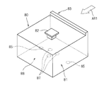
- FIG. 2 is a perspective view showing the configuration of the FOUP 80.
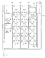
- FIG. 3 is a top view showing the overall configuration of the substrate processing system 1.
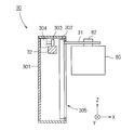
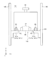
- FIG. 4 is a cross-sectional view of the FOUP holding unit 30 and the rail 32 taken along the ZX plane.
- FIG. 5 is a top view of the loader / unloader unit 100.
- FIG. 6 is a front view of the loader / unloader unit 100.
- FIG. 7 is a cross-sectional view of the shelf member 141 a and the FOUP 80.
- the substrate processing system 1 is a system that takes out a substrate from a FOUP (front opening unified pod) 80 that stores a plurality of substrates for each lot and processes the plurality of substrates.
- the substrate processing system 1 mainly includes a load port 10, a loader / unloader unit 100, a substrate processing apparatus group 200, and a FOUP transfer unit 300 (carrier transfer unit).
- a plurality of slots (not shown) each holding one substrate are formed inside the housing 81 of the FOUP 80, and the plurality of substrates are held in a state of being separated from each other in the vertical direction by the plurality of slots. It can be done. Further, a flange 82 is attached to the upper part of the casing 81 of the FOUP 80.
- the FOUP holding unit 30 carrier holding unit, which will be described later, holds the flange 82, whereby the FOUP 80 is held in a suspended state.
- a lid 83 is provided on one surface of the housing 81 (the surface viewed from the direction of the arrow AR1 in FIG. 2).
- the lid 83 is provided with a locking mechanism for the housing 81.
- the lock mechanism When the lock mechanism is operated in a state where the lid 83 is attached to the housing 81, the lid 83 is fixed to the housing 81, and the inside of the housing 81 is closed. Accordingly, the lid 83 can be attached to the housing 81 to cause the lock mechanism to function, and the inside of the housing 81 can be made a sealed space. Therefore, regardless of the cleanliness of the clean room in which the substrate processing system 1 is installed, the inside of the FOUP 80 is maintained at a high cleanness.
- the lid 83 can be removed from the housing 81, the substrate can be taken out from the inside of the housing 81, and the substrate can be stored inside the housing 81.
- the substrate can be housed in the casing 81 with their respective main surfaces extending in the horizontal direction and spaced apart in the vertical direction.
- a pair of first recesses 85 are formed on the bottom 88 of the housing 81 at positions close to both side surfaces of the housing 81.
- three second recesses 87 are formed in the vicinity of the center position of the bottom portion 88.
- the formation position of the 1st recessed part 85 and the 2nd recessed part 87 is shown with the virtual line.
- the three second recesses 87 are formed such that one side of a triangle formed by connecting them is parallel to the plane of the lid 83.
- the load port 10 is a mounting table on which a transfer device (for example, OHT (Overhead / Hoist / Transfer)) outside the substrate processing system 1 or a FOUP 80 delivered from an operator of the substrate processing system 1 is mounted.
- a transfer device for example, OHT (Overhead / Hoist / Transfer)
- FOUP 80 delivered from an operator of the substrate processing system 1 is mounted.
- the loader / unloader unit 100 is provided with two load ports 10, and one FOUP 80 is placed on the placement surface 10 a of each load port 10.
- the loader / unloader unit 100 functions as a FOUP storage unit (buffer) that temporarily stores the FOUP 80 therein.
- FOUP storage unit buffer
- two shutters 11 are provided on the side surface of the loader / unloader unit 100 on the load port 10 side. When the shutter 11 is opened, an opening that communicates the external space of the substrate processing system 1 and the internal space of the loader / unloader unit 100 is formed.
- the transfer robot 130a of the loader / unloader unit 100 can transfer the FOUP 80 between the load port 10 and the inner space of the loader / unloader unit 100 through the opening.
- the loader / unloader unit 100 is disposed at a location sandwiched between the load port 10 and the substrate processing apparatus group 200.
- the configuration including the load port 10 and the loader / unloader unit 100 functions as a first transfer unit that transfers the FOUP 80 between the substrate processing system 1 and the outside thereof.
- the substrate processing apparatus group 200 includes six substrate processing apparatuses 20 arranged in a row as shown in FIG.
- a loader / unloader unit 100 is adjacent to one side ( ⁇ Y direction side) of the plurality of substrate processing apparatuses 20 along the arrangement direction (Y direction) of the plurality of substrate processing apparatuses 20.
- the substrate processing apparatus group 200 different substrate processes may be executed in each substrate processing apparatus 20, or the same substrate process may be executed in each substrate processing apparatus 20.
- substrate process for example, board
- the FOUP transport unit 300 includes a rail 32 extending along the Y direction in a section from the loader / unloader unit 100 to the substrate processing apparatus 20 on the + Y direction side in the substrate processing apparatus group 200.
- a FOUP holding unit 30 that can run along the rail 32 and holds the FOUP 80. Therefore, the FOUP transport unit 300 can transport the FOUP 80 in both directions of the Y axis ( ⁇ Y direction).
- the FOUP 80 that stores the processed substrate is transported from the substrate processing apparatus 20 to the loader / unloader unit 100 by the FOUP transport unit 300.
- the FOUP 80 is temporarily held by the loader / unloader unit 100 and then moved to the load port 10. Then, this FOUP 80 (FOUP for storing processed substrates) is carried out from the load port 10 to the outside of the substrate processing system 1.
- the control unit 50 shown in FIG. 1 includes a memory 51 that stores programs, variables, and the like, and a CPU 52 that executes control in accordance with the programs stored in the memory 51.
- Each part in the substrate processing system 1 is electrically connected to the control unit 50 by a signal line (not shown). Therefore, the CPU 52 operates these units (control objects) at a predetermined timing according to the program stored in the memory 51.
- the program stored in the memory 51 is, for example, a program related to FOUP transport. By executing this program, the transport robot 130 transports the FOUP 80 in the loader / unloader unit 100, or the FOUP holding unit 30 transports the FOUP. The FOUP 80 is transported inside the unit 300.
- the program stored in the memory 51 is a program related to substrate transport, and by executing this program, the substrate transport unit 24 (described later) transports the substrate between the FOUP 80 and the processing unit 24.
- the loader / unloader unit 100 mainly includes two transfer robots 130 (130 a and 130 b), a shelf array 140, and placement units 150 and 160.
- a shelf array 140 in which a plurality of shelf members 141 are arranged on the XZ plane is arranged.
- a transfer robot 130a and a placement unit 150 are arranged between the shelf array 140 and the load port 10
- a transfer robot 130b and the placement unit 160 are arranged in the shelf array 140 and a substrate processing apparatus group. 200.
- the shelf array 140 is a storage unit that stores a plurality of FOUPs 80 (16 in the present embodiment). That is, the shelf array 140 accommodates not only the FOUP 80 that accommodates unprocessed substrates, but also the empty FOUP 80 after the substrates are taken out. As shown in FIGS. 5 and 6, the shelf arrangement 140 is a two-dimensional arrangement of a plurality of shelves along the vertical direction (Z-axis direction) and the horizontal direction (X-axis direction).
- Each of the plurality of shelves includes a pair of shelf members 141a.
- each shelf member 141a has a substantially L-shape, and is attached to a corresponding frame 145 so that the longitudinal direction of each shelf member 141a is substantially parallel to the Y-axis direction. It has been.
- a projection 142 corresponding to the first recess 85 provided in the bottom 88 of the FOUP 80 is provided on the surface of the shelf member 141a on the side where the FOUP 80 is placed. Therefore, the FOUP 80 can be stably held on the pair of shelf members 141a by fitting the projections 142 of the pair of shelf members 141a into the first recesses 85 of the FOUP 80.
- the pair of shelf members 141a are used as storage shelves for storing the FOUP 80, and the region sandwiched between the pair of shelf members 141a is used as the storage space 141 for storing the FOUP 80.
- an opening 146 larger than the size of the tip 139 of the transfer robot 130 (130a, 130b) is formed between the two shelf members 141a constituting the storage shelf. And as shown in FIG. 6, each opening part 146 is arrange
- each opening 146 of the plurality of storage shelves included in the shelf array 140 serves as a passing portion that allows the front end portion 139 to pass in the vertical direction.
- the transfer robots 130 a and 130 b are portions that transfer the FOUPs 80 arranged on the load port 10 side and the substrate processing apparatus group 200 side as viewed from the shelf array 140. That is, the transfer robot 130a is disposed on the opposite side of the transfer robot 130b with the shelf array 140 interposed therebetween.
- both robots 130a and 130b have substantially the same hardware configuration. Therefore, in the following description, when the transfer robot 130a and the transfer robot 130b are not distinguished, they are simply referred to as “transfer robot 130”.
- the front end 139 of the transfer robot 130 is a holding element that holds the FOUP 80 from below, and has a substantially triangular shape. Protrusions 139a are provided in the vicinity of the apexes on the upper surface side of the tip 139. Further, as described above, the bottom 88 of the FOUP 80 is provided with three second recesses 87 (see FIG. 7: two of the three are shown for convenience of illustration) corresponding to the protrusion 139a.
- the tip 139 is attached to the arm 138a via a rotation shaft 134b provided substantially parallel to the Z axis, and is rotatable about the rotation shaft 134b. Therefore, the transfer robot 130 stably holds the FOUP 80 by fitting the three protrusions 139a into the corresponding second recesses 87 of the FOUP 80 while rotating the tip 139.
- the arm 138a is attached to the arm 138b via a rotating shaft 134c provided substantially parallel to the Z axis
- the arm 138b is attached to the fixed base 136 via the rotating shaft 134a.
- the fixed base 136 is provided so as to be movable up and down on a column 131 extending in the vertical direction (Z-axis direction). Further, the support 131 can slide along a guide rail 132 extending in the horizontal direction (X-axis direction).
- the transfer robot 130 moves the FOUP 80 held by the tip 139 in the horizontal direction along the shelf array 140 and moves it up and down in the vertical direction. Therefore, the transfer robot 130 a transfers the FOUP 80 between the storage shelves of the shelf array 140, the load port 10, and the placement unit 150. Further, the transfer robot 130b transfers the FOUP 80 between the storage shelves in the shelf array 140 and the placement unit 160.
- the transport robot 130 a transports the FOUP 80 placed on the load port 10 to the shelf array 140, transports the FOUP 80 placed on the load port 10 to the placement unit 150, and places the FOUP 80 on the placement unit 150. Processing for transporting the placed FOUP 80 to the shelf array 140, processing for transporting the FOUP 80 stored in the shelf array 140 to the load port 10, and processing for transporting the FOUP 80 placed on the placement unit 150 to the load port 10 I do.
- the transfer robot 130a places the FOUP 80 so that the orientation of the lid 83 is in the + X direction. Further, when placing the FOUP 80 on the load port 10 and the shelf array 140, the transfer robot 130a places the FOUP 80 so that the direction of the lid 83 is the + Y direction.
- the transfer robot 130 b performs a process of transferring the FOUP 80 stored in the shelf array 140 to the placement unit 160 and a process of transferring the FOUP 80 placed on the placement unit 160 to the shelf array 140.
- the transfer robot 130b places the FOUP 80 so that the orientation of the lid 83 is in the + X direction. Further, when placing the FOUP 80 on the shelf array 140, the transfer robot 130b places the FOUP 80 so that the direction of the lid 83 is the + Y direction.
- the transfer robots 130a and 130b are arranged to face each other with the shelf array 140 interposed therebetween. Therefore, the transfer robots 130a and 130b can transfer a plurality of FOUPs 80 substantially simultaneously, and the throughput of the loader / unloader unit 100 as a whole can be improved. In addition, the transfer robots 130a and 130b can transfer the FOUP 80 without spatially interfering with each other except when accessing the same storage shelf. Therefore, the operation of each robot can be set without considering the interference of the transfer robots 130a and 130b.
- the transport of the FOUP 80 performed between the transport robot 130 (130a, 130b) and each storage shelf in the shelf array 140 is performed as follows. That is, when the FOUP 80 is transferred from the transfer robot 130 to the storage shelf, first, the height position (Z-axis direction position) of the bottom 88 of the FOUP 80 stored in the storage shelf is the upper surface 143 of the shelf member 141a (141b, 141c) 7), the tip 139 of the transfer robot 130 is moved so as to be higher than the height position. Next, the tip portion 139 is lowered, and the projections 142 of the pair of shelf members 141a (141b, 141c) are fitted into the first recess 85 of the FOUP 80.
- the FOUP 80 is placed on the upper surface 143 of the pair of shelf members 141a (141b, 141c), and the protrusion 139a of the tip 139 is separated from the second recess 87.
- the process of delivering the FOUP 80 from the transfer robot 130 to the storage shelf is completed.
- the tip 139 of the transfer robot 130 is moved below the FOUP 80 placed on the storage shelf.
- the tip 139 is raised, and the protrusion 139 a of the tip 139 is fitted into the second recess 87 of the FOUP 80.
- the FOUP 80 is held by the tip portion 139, and the protrusion 142 is separated from the first recess 85, whereby the process of delivering the FOUP 80 from the storage shelf to the transport robot 130 is completed. .
- the FOUP 80 is moved above the shelf members 141a (141b, 141c). Therefore, the height of the accommodation space 141 is set to be larger than the height of the FOUP 80.
- the placement unit 160 functions as a placement unit that temporarily holds the FOUP 80 transported from the shelf array 140 to the substrate processing apparatus 20.
- the placement unit 160 also functions as a placement unit that temporarily holds the FOUP 80 transported from the substrate processing apparatus 20 to the shelf array 140.
- the placement unit 160 includes a shelf member 141b on which the FOUP 80 is placed.
- the shelf member 141b has a pair of long members having a substantially L-shaped side shape when viewed in the -X direction, and a plurality of (three in this embodiment) protrusions on the surface on which the FOUP 80 is placed. It is a member which has. As shown in FIGS. 5 and 6, the shelf member 141b is disposed so that the longitudinal direction thereof is substantially parallel to the X-axis direction.
- the placement unit 150 functions as a placement unit that temporarily holds the FOUP 80 transported from the load port 10 and the shelf array 140 to the substrate processing apparatus 20.
- the placement unit 150 also functions as a placement unit that temporarily holds the FOUP 80 transported from the substrate processing apparatus 20 when transported to the load port 10 and the shelf array 140.
- the placement unit 150 includes a shelf member 141c on which the FOUP 80 is placed.
- the shelf member 141c has a pair of long members having a substantially L-shaped side shape when viewed in the -X direction, and a plurality of (three in this embodiment) protrusions on the surface on which the FOUP 80 is placed. It is a member which has. As shown in FIGS. 5 and 6, the shelf member 141 c is disposed such that its longitudinal direction is substantially parallel to the X-axis direction.
- the FOUP transport unit 300 includes a rail 32 extending along the Y direction in the section from the loader / unloader unit 100 to the substrate processing apparatus 20 on the + Y direction side in the substrate processing apparatus group 200, and the rail 32. And a FOUP holding unit 30 that holds the FOUP 80.
- the FOUP holding unit 30 will be described in detail with reference to FIG.
- the FOUP holding unit 30 includes a housing 301 having a hollow rectangular cross section, an actuator 302 attached to the inner wall of the housing 301, a motor 304 attached to the inner wall of the housing 301 and rotatable in forward and reverse directions, and the motor 304. And a pinion 303 attached to the rotating shaft.
- a rail 32 passes through the housing 301 in the Y-axis direction.
- a rack that meshes with the pinion 303 is cut on the upper surface of the rail 32 (not shown). Therefore, when the motor 302 rotates the pinion 303 in the forward / reverse direction, the FOUP holding unit 30 runs along the rails 32 in the ⁇ Y direction.
- a slit 305 that is long in the vertical direction is cut in the side surface of the housing 301 that faces the FOUP 80.
- the two grip portions 31 that hold the FOUP 80 are coupled to the actuator 302 via the slit 305.
- the actuator 302 moves the two grip portions 31 closer to and away from each other and moves them up and down.
- the rail 32 is configured by connecting a plurality of unit rails 320 in the Y direction. More specifically, the rail 32 has one unit rail 320 which is arranged on the most ⁇ Y direction side and is relatively short, and six units which are relatively long and have the same Y direction length as each substrate processing apparatus 20. The rail 320 and the rail 320 are connected to each other. The length of the rail 32 in the Y direction can be adjusted by attaching / detaching the unit rail 320.
- a unit rail 320 is added according to the length of the new substrate processing apparatus 20 in the Y direction to Additional adjustment is performed to increase the length in the Y direction.
- the unit rail 320 is removed according to the length of the existing substrate processing apparatus 20 in the Y direction. Removal adjustment is performed to shorten the length of 32 in the Y direction.
- the unit rail 320 is removed and the substrate processing apparatus 20 is added or removed as described above.
- the substrate processing system 1 can be expanded or reduced (addition or removal of the substrate processing apparatus 20) by an easy operation of removal.
- the substrate processing system 1 is connected to an external FOUP transfer means such as an OHT, and the first delivery unit (load port 10 and the Y port) provided on one side ( ⁇ Y direction side) of the substrate processing system 1.
- the loader / unloader unit 100) delivers the FOUP 80. Even if the substrate processing apparatus 20 is added to or removed from the substrate processing system 1, the length of the substrate processing system 1 only changes to the other side (+ Y direction side), and the position of the first delivery unit does not change. If the delivery position for delivering the FOUP 80 to / from the external FOUP transport unit changes according to the addition / removal of the substrate processing apparatus 20, the FOUP transport unit must be driven to compensate for the change. In this case, the control of the FOUP conveyance unit becomes complicated.
- the FOUP transport means since the delivery position of the FOUP 80 does not change regardless of the addition / removal of the substrate processing apparatus 20, the FOUP transport means does not become complicated. Such a mode is desirable compared to a mode in which the position of the first delivery unit moves as the substrate processing system expands or contracts, as in, for example, Japanese Patent No. 5392190.
- the FOUP holding unit 30 holds two rod-like gripping portions 31 that extend in the X direction and are separated in the Y direction.
- the FOUP holding part 30 can hold the two gripping parts 31 and displace them in the perspective direction (Y direction). For this reason, the FOUP holding unit 30 can switch between a state in which the flange 82 is gripped by bringing the two gripping portions 31 close to each other and a state in which the flange 82 is not gripped by moving the two gripping portions 31 away from each other.
- the FOUP holding unit 30 includes an elevating mechanism (the actuator 302 described above) that elevates and lowers the grip unit 31 along the Z direction. Furthermore, the FOUP holding unit 30 can slide in the Y direction along the rail 32 by a motor 304 (see FIG. 4). For this reason, the FOUP holding part 30 is movable along the Y direction and the Z direction.
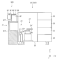
- FIG. 8 is a side view of the substrate processing apparatus 20 and the FOUP transport unit 300 as viewed from the AA cross section of FIG. 8 to 10 are side views showing a flow from when the FOUP 80 transported by the FOUP transport unit 300 is delivered to the substrate processing apparatus 20 until processing is performed on each substrate in the FOUP 80.
- FIG. 8 is a side view of the substrate processing apparatus 20 and the FOUP transport unit 300 as viewed from the AA cross section of FIG. 8 to 10 are side views showing a flow from when the FOUP 80 transported by the FOUP transport unit 300 is delivered to the substrate processing apparatus 20 until processing is performed on each substrate in the FOUP 80.
- Each substrate processing apparatus 20 constituting the substrate processing apparatus group 200 includes a second delivery unit 21 that delivers the FOUP 80 between the substrate processing apparatus 20 and the FOUP transport unit 300, and a FOUP 80 that is arranged in the second delivery unit 21.
- the substrate is transferred between the opening / closing unit 22 that opens and closes the lid 83, the plurality of processing units 23 that perform processing on the substrate, the FOUP 80 disposed in the second delivery unit 21, and the plurality of processing units 23.
- a substrate transfer unit 24 is arranged between the opening / closing unit 22 that opens and closes the lid 83, the plurality of processing units 23 that perform processing on the substrate, the FOUP 80 disposed in the second delivery unit 21, and the plurality of processing units 23.
- the second delivery unit 21 includes a mounting plate 211 on which the FOUP 80 is mounted, and an elevating unit 212 that moves the mounting plate 211 up and down.
- the height position (delivery position) of the mounting plate 211 when moved upward by the elevating unit 212 is the height of the lower surface of the FOUP 80 conveyed by the FOUP conveying unit 300 and the height of the upper surface of the mounting plate 211. It is a substantially coincident position.
- FIG. 8 shows a case where a FOUP 80 placed on the placement unit 150 or the placement unit 160 (see FIG. 4) in the loader / unloader unit 100 is transferred to a desired substrate processing apparatus in the substrate processing apparatus group 200 by the FOUP transport mechanism 300. Side surfaces of the substrate processing apparatus 20 and the FOUP transport unit 300 showing a state in which the FOUP 80 is mounted on the mounting unit 211 after being transported in the Y direction to the mounting unit 211 of the second delivery unit 21 facing 20.
- the two holding units 31 are separated from the state in which the FOUP holding unit 30 holds the FOUP 80 immediately above the mounting plate 211 at the delivery position. .
- the state in which the FOUP 80 is held by the FOUP holding unit 30 is switched to the state in which the FOUP 80 is placed on the placement plate 211.
- the FOUP holding unit 30 holds the two gripping units 31 immediately above the placement plate 211 on which the FOUP 80 is placed at the delivery position. Move closer.
- the state in which the FOUP 80 is placed on the placement plate 211 is switched to the state in which the FOUP 80 is gripped by the FOUP holding unit 30.
- each substrate processing apparatus 20 two placement plates 211 are provided adjacent to each other in the Y direction, and the lifting unit 212 individually attaches these two placement plates 211. Raise and lower. Thereby, in each substrate processing apparatus 20, the FOUP 80 can be delivered between the FOUP holding unit 30 and the second delivery unit 21 at two locations adjacent in the Y direction.
- FIG. 9 is a side view of the substrate processing apparatus 20 and the FOUP transport unit 300 when the placement plate 211 is positioned at the standby position.
- the substrate transport unit 24 sequentially transports the substrates in the FOUP 80 arranged at the standby position to the processing units 23, and the substrates completed by the processing units 23 are sequentially arranged at the standby position. Carry in.
- the FOUP 80 waits at the standby position until all the substrates (one lot of substrates) originally stored in the FOUP 80 are processed and all the processed substrates return to the FOUP 80.
- the elevating unit 212 raises the mounting plate 211 and the FOUP 80 is moved to the delivery position. Then, the FOUP 80 storing the processed substrate is transported to the loader / unloader unit 100 by the FOUP transport unit 300 and transported to the outside of the substrate processing system 1 through the load port 10.
- the mounting plate 211 is basically maintained at the standby position, and is raised to the delivery position only when the FOUP 80 is delivered to the FOUP holding unit 30. Accordingly, it is possible to effectively suppress a situation in which the conveyance of the FOUP 80 by the FOUP holding unit 30 is hindered by the presence of another FOUP 80 located at the delivery position.
- the substrate processing apparatus 20 is provided with an apparatus wall 25 for accommodating the opening / closing section 22, the processing section 23, and the substrate transport section 24, and the second delivery section 21 is provided adjacent to the ⁇ X side of the apparatus wall 25. It has been.
- two shutters (not shown) are provided at positions corresponding to the two lids 83 of the two FOUPs 80 arranged on the two placement plates 211 located at the standby position. ing. When the shutter is opened, an opening that communicates the external space of the device wall 25 and the internal space of the device wall 25 is formed.
- the opening / closing part 22 mainly includes a latch part 221 and a drive part 222 that moves the latch part 221 in the Z direction and the X direction.
- the latch portion 221 has a shape that can be fitted to the lid 83 of the FOUP 80. Therefore, when the driving unit 222 moves the latch unit 221, the latch unit 221 reaches the lid 83 through the opening. After the latch part 221 is moved to reach and fit the lid 83, the latch part 221 holding the lid 83 returns to a fixed position in the apparatus wall 25, so that the lid 83 of the FOUP 80 is opened.
- FIG. 10 is a side view of the substrate processing apparatus 20 and the FOUP transport unit 300 at this time.
- the period from when the substrate transport unit 24 starts transporting a plurality of substrates in the FOUP 80 to each processing unit 23 to when the substrate transport unit 24 returns the plurality of substrates processed in each processing unit 23 into the FOUP 80 is The state where the lid 83 is opened is maintained. When all the processed substrates are returned into the FOUP 80, the opening / closing unit 22 attaches the lid 83 to the FOUP 80 and seals the FOUP 80.
- the substrate transport unit 24 includes two hands 241 (substrate holding means) for supporting the substrate and a hand drive mechanism 242 that moves the two hands 241 independently.
- Each hand 241 is moved forward and backward and moved up and down by being driven by the hand drive mechanism 242, and delivers the substrate to the FOUP 80 on the mounting plate 211 in the standby position through the opening. Further, each hand 241 is moved forward and backward and moved up and down by being driven by the hand drive mechanism 242, and delivers a substrate to and from each processing unit 23.
- the processing unit 23 is a part that executes a predetermined process such as a cleaning process on the substrate in the chamber.
- a predetermined process such as a cleaning process on the substrate in the chamber.
- two multistage configurations in which four processing units 23 are stacked in the vertical direction are provided adjacent to each other in the Y direction, and a total of eight processing units 23 are provided (FIG. 3). And FIGS. 8 to 10).
- the number and arrangement of the processing units 23 can be set as appropriate.
- a mode in which each processing unit 23 performs the same processing (substrate cleaning processing) will be described, but each processing unit 23 may perform different processing.
- the unprocessed substrate is transported to the second delivery unit 21 in a state of being stored in the FOUP 80. Since the second delivery unit 21 is in the vicinity of the processing unit 23, the unprocessed substrate can be transported to the vicinity of the processing unit 23 while being isolated from the external atmosphere. Therefore, during a period in which the substrate is exposed to the atmosphere outside the FOUP 80, the substrate transport unit 24 starts processing a plurality of substrates in the FOUP 80 to each processing unit 23, and then the substrate transport unit 24 performs processing in each processing unit 23. This is a period until a plurality of executed substrates are returned to the FOUP 80.
- the substrate is exposed to the atmosphere outside the FOUP 80 as compared to other modes in which the FOUP 80 is opened in the loader / unloader unit 100 (for example, the mode described in JP-A-2006-237559).
- the time is short and contamination to the substrate can be effectively suppressed.
- each substrate processing apparatus 20 of the substrate processing apparatus group 200 has one substrate transport section 24 disposed at an intermediate position between the FOUP 80 disposed in the second delivery section 21 and the plurality of processing sections 23.
- the substrate is transferred to and from the unit 23.
- each substrate is transported by one substrate transport unit 24 that does not move from the central position
- the mode in which the substrate is transported via a plurality of substrate transport units Compared with the mode in which the substrate transport unit moves while being held, the time during which the substrate is exposed to the atmosphere outside the FOUP 80 is short, and contamination of the substrate can be more effectively suppressed.
- the mode in which the FOUP is used as the carrier storing the substrates for each lot has been described, but other substrate containers may be used as the carrier.
- the mode in which the same substrate processing (substrate cleaning processing) is executed in each substrate processing apparatus 20 has been described, but different substrate processing may be executed in each substrate processing apparatus 20.
- the FOUP 80 that stores one lot of substrates that have been subjected to substrate processing in a certain substrate processing apparatus 20 is loaded via the loader / unloader unit 100. 10 and is carried out of the substrate processing system 1.
- a FOUP 80 that stores one lot of substrates that have been subjected to substrate processing in a certain substrate processing apparatus 20 is transferred to another substrate processing apparatus 20. Further, other substrate processing may be performed.
- the FOUP transport unit 300 can transport the FOUP 80 bi-directionally ( ⁇ Y direction) along the arrangement direction of the substrate processing apparatus group 200 as in the above-described embodiment, the FOUP 80 is moved only in one direction. Unlike the transportable mode, the arrangement of the substrate processing apparatuses 20 can be freely performed without being limited to the substrate processing order.
- the time interval from one process to the next process is shorter than in the aspect in which different processes are sequentially executed in a plurality of processing devices. . Therefore, in the aspect in which the substrate processing apparatus has a plurality of processing units having different processing contents, for example, when the substrate is subjected to a cleaning process after the heating process for heating the substrate to a predetermined temperature, the time interval between the processes is set. This is especially effective when you want to shorten it.
- the second delivery unit 21 may further include a buffer unit that temporarily holds the FOUP 80 in addition to the placement plate 211 and the lifting unit 212.
- the rail 32 is arranged on the most ⁇ Y side and has one unit rail 320 that is relatively short, and six unit rails 320 that are relatively long and have the same length in the Y direction as each substrate processing apparatus 20.
- the length of each unit rail 320 may be the same length (reference length), and the length in the Y direction of each substrate processing apparatus 20 may be a length corresponding to an integral multiple of the reference length.
- the number of unit rails 320 corresponding to the length of the existing substrate processing apparatus 20 in the Y direction is removed, and the Y of the rail 32 is removed. Removal adjustment is performed to shorten the length in the direction.
- the length of each unit rail 320 is the same, management of each unit rail 320 is easy.
- the length of each substrate processing apparatus 20 in the Y direction is a length corresponding to an integral multiple of the reference length, an integer number of unit rails 320 should be attached or removed according to the addition or removal of the substrate processing apparatus 20.
- the length of the substrate processing apparatus group 200 in the Y direction can be made to correspond to the length of the rail 32 in the Y direction.
- the FOUP holding unit 30 that self-runs along the rail 32 by the motor 304 disposed inside is described, but the moving means of the FOUP holding unit 30 is not limited to this.
- the moving means of the FOUP holding unit 30 is configured. May be.
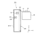
- a FOUP holding unit 30A shown in FIGS. 11 and 12 may be used.
- a ball screw 308 is disposed along the rail 32.
- the ball screw 308 passes through the housing 301A of the FOUP holding unit 30A in the Y direction, and is screwed with a nut 306 disposed inside the FOUP holding unit 30A.
- the end of the ball screw 308 on the ( ⁇ Y direction) side is connected to a motor 307 disposed in the loader / unloader unit 100. Therefore, by rotating the rotating shaft of the motor 307 in the forward / reverse direction, the ball screw 308 rotates and the FOUP holding unit 30 can be moved along the rails 32 in the ⁇ Y direction.
Landscapes
- Container, Conveyance, Adherence, Positioning, Of Wafer (AREA)
Abstract
基板の汚染を抑制可能であり、レイアウトの自由度が高い基板処理システムを提供する。FOUP搬送部300が長さ調整可能なレール32および自走可能なFOUP保持部30によって構成される。このため、単位レール320の付け外しおよび基板処理装置20の追加もしくは除去という容易な作業によって、基板処理システム1の拡張または縮小(基板処理装置20の追加または除去)を行うことができる。また、FOUP搬送部300は、基板が収納されたFOUP80を各基板処理装置20まで搬送する。このため、基板がFOUP80外部の雰囲気に晒される時間が短く、基板への汚染を有効に抑制することができる。
Description
本発明は、基板処理システムに関する。
従来より、複数の基板を収納したキャリアを搬送し、該キャリアから基板を取り出して処理を行う基板処理システムが知られている。
例えば、引用文献1には、ローダ・アンローダ部にてキャリアを収容し、ローダ・アンローダ部はキャリアを基板処理システムに隣接する位置まで移動させ、基板処理システム内の搬送機構がキャリアから基板を取り出し、該キャリアから取出された基板を基板処理システム内の各処理装置まで搬送して処理を行う技術が開示されている。
また、引用文献2には、共有搬入ポートから共有搬出ポートに向けて伸びる専用搬送路を用いてキャリアが搬送され、その搬送過程で各処理装置においてキャリアから基板を取出して処理を行う技術が開示されている。
しかしながら、特許文献1の技術では、基板処理システム内とは言え、キャリアから取り出された状態で基板が各処理装置まで搬送されるため、基板がキャリア外部の雰囲気に晒される時間が長くなり、基板が汚染されやすくなるという問題がある。
引用文献2の技術では、キャリア搬送が一方向に沿って行われるため、例えば、処理順序に沿って各処理装置を配置する必要が生じるなど、各処理装置の配置に制限が課される。また、引用文献2の技術では、処理装置を追加または除去した場合に、共有搬入ポートまたは共有搬出ポートの少なくとも一方が移動することになる。このため、引用文献2の技術では、基板処理システムと外部装置との間でのキャリアの受渡しを行う観点から、上記移動の影響を相殺するように外部装置の駆動制御を実行する必要が生じ、基板処理システムの拡大または縮小(処理装置の追加または除去)に伴う手間が大きくなる。すなわち、引用文献2の技術では、基板処理システムにおけるレイアウトの自由度が低い。
そこで、本発明では、基板の汚染を抑制可能であり、レイアウトの自由度が高い基板処理システムを提供することを目的とする。
本発明の第1の態様にかかる基板処理システムは、基板を収納したキャリアから基板を取り出して処理を行う基板処理システムであって、該基板処理システムとその外部との間で前記キャリアが受け渡される第1受渡し部と、複数の基板処理装置が一列に配され、その配列方向に沿って前記複数の基板処理装置の一方側に前記第1受渡し部が隣接する基板処理装置群と、前記第1受渡し部および前記基板処理装置群の配列方向に沿って双方向に前記キャリアを搬送するキャリア搬送部と、を備え、前記基板処理装置群を構成する各基板処理装置は、基板処理装置と前記キャリア搬送部との間で前記キャリアが受け渡される第2受渡し部と、前記基板に処理を実行する複数の処理部と、前記第2受渡し部に配される前記キャリアと前記複数の処理部との間で前記基板を搬送する少なくとも1つの基板搬送部と、を有することを特徴とする。
本発明の第2の態様にかかる基板処理システムは、本発明の第1の態様にかかる基板処理システムであって、前記キャリア搬送部は、前記第1受渡し部から前記基板処理装置群における他方側の基板処理装置までの区間で前記配列方向に沿って伸びるレールと、前記レールに沿って自走可能であり前記キャリアを保持するキャリア保持部と、を有することを特徴とする。
本発明の第3の態様にかかる基板処理システムは、第2の態様にかかる基板処理システムであって、前記レールは複数の単位レールを前記配列方向に連結して構成されており、前記単位レールの付け外しにより前記レールの前記配列方向における長さを調整可能であることを特徴とする。
本発明の第4の態様にかかる基板処理システムは、本発明の第3の態様にかかる基板処理システムであって、前記単位レールの前記配列方向の長さは基準長であり、各基板処理装置の前記配列方向の長さは前記基準長の整数倍に応じた長さであり、前記基板処理装置群に新たな基板処理装置を追加する場合には、該新たな基板処理装置の前記配列方向における長さに応じた数の前記単位レールを追加して前記レールの前記配列方向における長さを長くする追加調整と、前記基板処理装置群から既存の基板処理装置を除去する場合には、該既存の基板処理装置の前記配列方向における長さに応じた数の前記単位レールを除去して前記レールの前記配列方向における長さを短くする除去調整と、を実行可能であることを特徴とする。
本発明の第5の態様にかかる基板処理システムは、本発明の第1の態様ないし第4の態様のいずれかにかかる基板処理システムであって、前記基板処理装置群のうち少なくとも1つの基板処理装置は、処理内容が互いに異なる複数の処理部を有し、該少なくとも1つの基板処理装置では、各基板が前記複数の処理部において順次に異なる処理を実行されることを特徴とする。
本発明の第6の態様にかかる基板処理システムは、本発明の第1の態様ないし第5の態様のいずれかにかかる基板処理システムであって、前記基板処理装置群のうち少なくとも1つの基板処理装置は、前記第2受渡し部に配される前記キャリアと前記複数の処理部との中間位置に配される1つの基板搬送部を有し、前記1つの基板搬送部は、複数の基板保持手段をそれぞれ個別に駆動させることで、前記中間位置から移動することなく、前記第2受渡し部に配される前記キャリアと前記複数の処理部との間で前記基板を搬送することを特徴とする。
本発明では、基板処理システムの一方側に第1受渡し部が配される。このため、第1受渡し部の位置を動かすことなく、基板処理システムの拡張または縮小を行うことができる。第1受渡し部の位置が移動する場合、基板処理システムと外部装置との間でのキャリアの受渡しを行う観点から、上記移動の影響を相殺するように外部装置の駆動制御を実行する必要が生じる。したがって、本発明の態様は、例えば特許第5392190号公報のように基板処理システムの拡張または縮小に伴って第1受渡し部の位置が動く態様に比べ、上記駆動制御の必要が生じず望ましい。
また、本発明では、キャリア搬送部が、第1受渡し部および基板処理装置群の配列方向に沿って双方向にキャリアを搬送可能である。このため、本発明の態様では、キャリア搬送部が上記配列方向に沿って一方向にのみキャリアを搬送可能な態様に比べて、各基板処理装置の配置の自由度が高く望ましい。
また、本発明では、基板を収納したキャリアが、キャリア搬送部によって各基板処理装置の第2受渡し部まで搬送される。このため、基板がキャリア外部の雰囲気に晒される時間が短く、基板への汚染を有効に抑制することができる。
以下、図面を参照しながら、本発明の実施形態について説明する。図面では同様な構成および機能を有する部分に同じ符号が付され、重複説明が省略される。なお、以下の実施形態は、本発明を具体化した一例であり、本発明の技術的範囲を限定する事例ではない。また、図面においては、理解容易のため、各部の寸法や数が誇張または簡略化して図示されている場合がある。また、図面には、方向を説明するためにXYZ直交座標軸がふされる場合がある。座標軸における+Z方向は鉛直上方向であり、XY平面は水平面である。
<1 実施形態>
<1.1 基板処理システムの概略構成>
図1は、基板処理システム1の全体構成を示す斜視図である。図2は、FOUP80の構成を示す斜視図である。図3は、基板処理システム1の全体構成を示す上面図である。図4はFOUP保持部30およびレール32をZX平面で切った断面図である。図5は、ローダ・アンローダ部100の上面図である。図6は、ローダ・アンローダ部100の正面図である。図7は棚部材141aおよびFOUP80の断面図である。
<1.1 基板処理システムの概略構成>
図1は、基板処理システム1の全体構成を示す斜視図である。図2は、FOUP80の構成を示す斜視図である。図3は、基板処理システム1の全体構成を示す上面図である。図4はFOUP保持部30およびレール32をZX平面で切った断面図である。図5は、ローダ・アンローダ部100の上面図である。図6は、ローダ・アンローダ部100の正面図である。図7は棚部材141aおよびFOUP80の断面図である。
基板処理システム1は、複数の基板をロット毎に収納したFOUP(front opening unified pod)80から基板を取り出し、この複数の基板に処理を行うシステムである。基板処理システム1は、主として、ロードポート10と、ローダ・アンローダ部100と、基板処理装置群200と、FOUP搬送部300(キャリア搬送部)と、を備える。
まず、図2を参照してFOUP80の構成について説明する。FOUP80の筐体81の内部にはそれぞれが1枚の基板を保持する複数のスロット(不図示)が形成されており、これら複数のスロットによって複数枚の基板を上下方向に互いに離間した状態で保持できるようになっている。また、FOUP80の筐体81上部には、フランジ82が付設されている。後述するFOUP保持部30(キャリア保持部)がこのフランジ82を把持することにより、FOUP80は吊り下げた状態にて保持される。
また、筐体81の一面(図2中の矢印AR1の向きから見た面)には蓋83が設けられる。蓋83には筐体81に対するロック機構が設けられている。蓋83を筐体81に取り付けた状態でロック機構を機能させると、蓋83が筐体81に固定されて筐体81内部が密閉された閉空間となる。これにより、蓋83を筐体81に装着してロック機構を機能させ、筐体81内部を密閉空間とすることができる。そのため、基板処理システム1が設置されたクリーンルームの清浄度にかかわらず、FOUP80内部は高い清浄度に維持される。一方、上記のロック機構を解除すると、蓋83を筐体81から取り外すことが可能となり、筐体81の内部から基板を取り出すこと、および、筐体81の内部に基板を収納することが可能となる。なお、筐体81には、例えば25枚の基板をそれぞれの主面を水平方向に沿わせて上下方向に離間して収納する。
また、筐体81の底部88には、筐体81の両側面に近い位置に一対の第1凹部85が形成されている。さらに、底部88の中心位置近傍には3個の第2凹部87が形成されている。図2では第1凹部85および第2凹部87の形成位置を仮想線で示している。3個の第2凹部87はこれらを結んで形成される三角形の一辺が蓋83の平面と平行となるように形成されている。
ロードポート10は、基板処理システム1の外部の搬送装置(例えば、OHT(Overhead Hoist Transfer))や、基板処理システム1のオペレータから受け渡されるFOUP80を載置する載置台である。図1に示すように、ローダ・アンローダ部100には2台のロードポート10が並設され、各ロードポート10の載置面10a上には各1個のFOUP80が載置される。
ローダ・アンローダ部100は、FOUP80をその内部に一時的に収容するFOUP収容部(バッファ)として機能する。ローダ・アンローダ部100のロードポート10側の側面には、図1および図5に示すように、2個のシャッター11が設けられている。シャッター11が開放されると、基板処理システム1の外部空間とローダ・アンローダ部100の内部空間とを連通する開口部が形成される。
そのため、ローダ・アンローダ部100の搬送ロボット130aは、この開口部を介してロードポート10とローダ・アンローダ部100の内側空間との間でFOUP80の搬送を行うことができる。本実施形態では、図1に示すように、ローダ・アンローダ部100は、ロードポート10と基板処理装置群200とに挟まれた場所に配置される。ロードポート10およびローダ・アンローダ部100から成る構成は、基板処理システム1とその外部との間でFOUP80が受け渡される第1受渡し部として機能する。
基板処理装置群200は、図1に示すように6個の基板処理装置20が一列に配されて構成される。複数の基板処理装置20の配列方向(Y方向)に沿って、複数の基板処理装置20の一方側(-Y方向側)にはローダ・アンローダ部100が隣接する。
基板処理装置群200においては、各基板処理装置20で異なる基板処理が実行される態様でも構わないし、各基板処理装置20で同一の基板処理が実行される態様でも構わない。以下では、各基板処理装置20で同一の基板処理(例えば、基板洗浄処理)が実行される態様について説明する。
図3および図5に示すように、FOUP搬送部300は、ローダ・アンローダ部100から基板処理装置群200における+Y方向側の基板処理装置20までの区間でY方向に沿って伸びるレール32と、レール32に沿って自走可能でありFOUP80を保持するFOUP保持部30と、を有する。このため、FOUP搬送部300はY軸の双方向(±Y方向)にFOUP80を搬送することが可能である。
未処理の基板を収納するFOUP80は、まず、基板処理システム1の外部からロードポート10を経て基板処理システム1に搬入される。このFOUP80は、ロードポート10からローダ・アンローダ部100に移動されてローダ・アンローダ部100内に設けられた複数の収容空間141(図5、図6参照)のいずれかに一時的に保持された後、FOUP搬送部300によって基板処理装置群200のうちいずれかの基板処理装置20に搬送される。基板処理装置20は、FOUP80から取出した各基板に洗浄処理を実行し、処理済みの各基板を再びFOUP80に収納する。処理済みの基板を収納するFOUP80は、FOUP搬送部300によって基板処理装置20からローダ・アンローダ部100に搬送される。このFOUP80は、ローダ・アンローダ部100で一時的に保持された後、ロードポート10に移動される。そして、このFOUP80(処理済みの基板を収納するFOUP)がロードポート10から基板処理システム1の外部へと搬出される。
図1に示す制御ユニット50は、プログラムや変数等を格納するメモリ51と、メモリ51に格納されたプログラムに従った制御を実行するCPU52とを備える。また、基板処理システム1内の各部は、不図示の信号線によって制御ユニット50と電気的に接続される。したがって、CPU52は、メモリ51に格納されているプログラムに従って、これら各部(制御対象)を所定のタイミングで動作させる。メモリ51に格納されているプログラムは、例えばFOUP搬送に関するプログラムであり、このプログラムを実行することにより、搬送ロボット130がローダ・アンローダ部100内でFOUP80を搬送したり、FOUP保持部30がFOUP搬送部300の内部でFOUP80を搬送したりする。あるいは、メモリ51に格納されているプログラムは、基板搬送に関するプログラムであり、このプログラムを実行することにより、基板搬送部24(後述)がFOUP80と処理ユニット24との間で基板を搬送する。
<1.2 各部の詳細な構成>
図5および図6に示すように、ローダ・アンローダ部100は、主として、2つの搬送ロボット130(130a、130b)と、棚配列140と、載置部150、160とを備える。
図5および図6に示すように、ローダ・アンローダ部100は、主として、2つの搬送ロボット130(130a、130b)と、棚配列140と、載置部150、160とを備える。
図5に示すように、ローダ・アンローダ部100内には、XZ平面に複数の棚部材141を配列した棚配列140が配置されている。また、ローダ・アンローダ部100内には搬送ロボット130aおよび載置部150が棚配列140とロードポート10との間に配置され、搬送ロボット130bおよび載置部160が棚配列140と基板処理装置群200との間に配置されている。
棚配列140は、FOUP80を複数(本実施の形態では16個)収容する収容部である。すなわち、棚配列140には、未処理基板を収容したFOUP80だけでなく、基板が取り出された後の空のFOUP80も収容される。図5および図6に示すように、棚配列140は、複数の棚を鉛直方向(Z軸方向)と水平方向(X軸方向)に沿って2次元的に配列させたものである。
複数の棚のそれぞれは、一対の棚部材141aを備える。図7に示すように、各棚部材141aは、略L字型の形状を有しており、各棚部材141aの長尺方向がY軸方向と略平行となるように対応するフレーム145に取り付けられている。また、棚部材141aについてFOUP80が載置される側の面には、FOUP80の底部88に設けられた第1凹部85に対応する突起部142が設けられている。したがって、FOUP80の第1凹部85に一対の棚部材141aの突起部142を嵌め合わせることにより、FOUP80を一対の棚部材141aに安定して保持できる。
このように、本実施形態において、一対の棚部材141aはFOUP80を収容する収容棚として、また、一対の棚部材141aに挟まれる領域は、FOUP80を収容する収容空間141として使用される。
また、収容棚を構成する2つの棚部材141aの間には、搬送ロボット130(130a、130b)の先端部139のサイズより大きな開口部146が形成されている。そして、図6に示すように、各開口部146は鉛直方向(Z軸方向)に沿って配置される。
したがって、搬送ロボット130の先端部139は、これら開口部146を通過しつつ棚配列140の内部を昇降する。すなわち、棚配列140に含まれる複数の収容棚のそれぞれの開口部146は、先端部139を鉛直方向に通過可能とする通過部となる。
搬送ロボット130a、130bは、図5に示すように、棚配列140から見てロードポート10側および基板処理装置群200側にそれぞれ配置されたFOUP80を搬送する部分である。すなわち、搬送ロボット130aは、棚配列140を挟んで搬送ロボット130bと逆側に配設されている。
なお、本実施形態において、両ロボット130a、130bは、略同一のハードウェア構成を有する。したがって、以下の説明において、搬送ロボット130aと搬送ロボット130bとを区別しない場合には、単に「搬送ロボット130」と称する。
搬送ロボット130の先端部139は、FOUP80を下側から保持する保持要素であり、略三角形状を有する。先端部139の上面側の各頂点付近には、突起部139aが設けられている。また、先述したようにFOUP80の底部88には、突起部139aと対応する3つの第2凹部87(図7参照:図示の都合上、3つのうち2つを記載)が設けられている。また、先端部139は、Z軸と略平行に設けられた回転軸134bを介してアーム138aに取り付けられており、回転軸134bを中心として回転可能とされる。したがって、搬送ロボット130は、先端部139を回転させつつ、3つの突起部139aをFOUP80の対応する第2凹部87に嵌め合わせることにより、FOUP80を安定して保持する。
さらに、アーム138aは、Z軸と略平行に設けられた回転軸134cを介してアーム138bに取り付けられ、アーム138bは、回転軸134aを介して固定台136に取り付けられる。また、固定台136は、鉛直方向(Z軸方向)に伸びる支柱131に昇降可能に設けられている。さらに、支柱131は、水平方向(X軸方向)に伸びるガイドレール132に沿って摺動可能である。
これにより、搬送ロボット130(130a、130b)は、先端部139に保持されたFOUP80を棚配列140に沿って水平方向に移動させるとともに鉛直方向に昇降させる。そのため、搬送ロボット130aは、棚配列140の収容棚、ロードポート10、および載置部150の間でFOUP80を搬送する。また、搬送ロボット130bは、棚配列140の収容棚と、載置部160との間でFOUP80を搬送する。
搬送ロボット130aは、ロードポート10に載置されたFOUP80を棚配列140へ搬送する処理と、ロードポート10に載置されたFOUP80を載置部150へ搬送する処理と、載置部150に載置されたFOUP80を棚配列140へ搬送する処理と、棚配列140に収納されたFOUP80をロードポート10へ搬送する処理と、載置部150に載置されたFOUP80をロードポート10へ搬送する処理を行う。なお、搬送ロボット130aは、FOUP80を載置部150に載置する場合には、蓋83の向きが+X向きの状態となるようにFOUP80を載置する。また、搬送ロボット130aは、FOUP80をロードポート10および棚配列140に載置する場合には、蓋83の向きが+Y向きとなるようにFOUP80を載置する。
また、搬送ロボット130bは、棚配列140に収納されたFOUP80を載置部160へ搬送する処理と、載置部160に載置されたFOUP80を棚配列140へ搬送する処理を行う。なお、搬送ロボット130bは、FOUP80を載置部160に載置する場合には、蓋83の向きが+X向きの状態となるようにFOUP80を載置する。また、搬送ロボット130bは、FOUP80を棚配列140に載置する場合には、蓋83の向きが+Y向きとなるようにFOUP80を載置する。
本実施形態では、搬送ロボット130a、130bは、棚配列140を挟んで対向して配置されている。このため、搬送ロボット130a、130bによって複数のFOUP80の搬送を略同時に実行でき、ローダ・アンローダ部100全体としてのスループットを向上させることができる。また、同一の収容棚にアクセスする場合を除いて、搬送ロボット130a、130bは、空間的に相互に干渉することなくFOUP80の搬送を実行できる。そのため、搬送ロボット130a、130bの干渉を考慮することなく各ロボットの動作を設定できる。
なお、搬送ロボット130(130a、130b)と棚配列140の各収容棚との間で行われるFOUP80の搬送は以下のように行われる。すなわち、搬送ロボット130から収容棚にFOUP80を受け渡す場合、まず、収容棚に収容するFOUP80の底部88の高さ位置(Z軸方向位置)が棚部材141a(141b、141c)の上面143(図7参照)の高さ位置より高くなるように、搬送ロボット130の先端部139を移動させる。次に、先端部139を下降させ、FOUP80の第1凹部85に一対の棚部材141a(141b、141c)の突起部142を嵌め合わせる。
そして、先端部139をさらに下降させることによって、FOUP80が一対の棚部材141a(141b、141c)の上面143に載置されるとともに、第2凹部87から先端部139の突起部139aが離隔することにより、搬送ロボット130から収容棚にFOUP80を受け渡す処理が完了する。
他方、収容棚から搬送ロボット130にFOUP80を受け渡す場合、まず、収容棚に載置されたFOUP80の下方に搬送ロボット130の先端部139を移動させる。次に、先端部139を上昇させ、FOUP80の第2凹部87に先端部139の突起部139aを嵌め合わせる。
そして、先端部139をさらに上昇させることによって、FOUP80が先端部139に保持され、第1凹部85から突起部142が離隔することにより、収容棚から搬送ロボット130にFOUP80を受け渡す処理が完了する。
このように、搬送ロボット130と収容棚との間でFOUP80の搬送を行う過程において、FOUP80は、棚部材141a(141b、141c)の上方に移動させられる。そのため、収容空間141の高さはFOUP80の高さより大きくなるように設定されている。
載置部160は、棚配列140から基板処理装置20へ搬送されるFOUP80を一時的に保持する載置部として機能する。また、載置部160は基板処理装置20から棚配列140へ搬送されるFOUP80を一時的に保持する載置部としても機能する。
載置部160は、FOUP80を載置する棚部材141bを有する。棚部材141bは、-X方向視の側面形状が略L字型を有する一対の長尺部材を有しており、FOUP80が載置される面に複数(本実施形態では3つ)の突起部を有する部材である。図5および図6に示すように、棚部材141bの長尺方向がX軸方向と略平行となるように配設される。
載置部150は、ロードポート10および棚配列140から基板処理装置20へと搬送されるFOUP80を一時的に保持する載置部として機能する。また、載置部150は基板処理装置20から搬送されるFOUP80をロードポート10および棚配列140に搬送する際に一時的保持する載置部としても機能する。
載置部150は、FOUP80を載置する棚部材141cを有する。棚部材141cは、-X方向視の側面形状が略L字型を有する一対の長尺部材を有しており、FOUP80が載置される面に複数(本実施形態では3つ)の突起部を有する部材である。図5および図6に示すように、棚部材141cはその長尺方向がX軸方向と略平行となるように配設される。
図3に示すように、FOUP搬送部300は、ローダ・アンローダ部100から基板処理装置群200における+Y方向側の基板処理装置20までの区間でY方向に沿って伸びるレール32と、レール32に沿って自走可能でありFOUP80を保持するFOUP保持部30と、を有する。
図4を用いてFOUP保持部30について詳述する。FOUP保持部30は中空の矩形断面の筐体301と、筐体301の内壁に取り付けられたアクチュエータ302と、筐体301の内壁に取り付けられ正逆方向に回転可能なモータ304と、該モータ304の回転軸に取り付けられたピニオン303、とを有している。筐体301にはレール32がY軸方向に貫通している。該レール32の上面にはピニオン303と歯合するラックが切られている(不図示)。よって、モータ302がピニオン303を正逆方向に回転すると、FOUP保持部30はレール32に沿って±Y方向に自走する。
筐体301のFOUP80に対向する側の側面には上下方向に長尺なスリット305が切開されている。FOUP80を保持する2つの把持部31は、スリット305を経由してアクチュエータ302に連結されている。アクチュエータ302は、2つの把持部31を互いに接近離反させると共に、上下方向に移動させる。
レール32は複数の単位レール320をY方向に連結して構成されている。より具体的には、レール32は、最も-Y方向側に配され相対的に短い1つの単位レール320と、相対的に長く各基板処理装置20と同一のY方向長さを持つ6つの単位レール320と、が連結されて構成されている。レール32は、単位レール320の付け外しにより、Y方向における長さが調整可能とされている。
基板処理システム1において基板処理装置群200に新たな基板処理装置20を追加する場合には、該新たな基板処理装置20のY方向における長さに応じて単位レール320を追加してレール32のY方向における長さを長くする追加調整が実行される。また、基板処理システム1において基板処理装置群200から既存の基板処理装置20を除去する場合には、該既存の基板処理装置20のY方向における長さに応じて単位レール320を除去してレール32のY方向における長さを短くする除去調整が実行される。
本実施形態のようにFOUP搬送部300が長さ調整可能なレール32および自走可能なFOUP保持部30によって構成される場合、上述の通り単位レール320の付け外しおよび基板処理装置20の追加もしくは除去という容易な作業によって基板処理システム1の拡張または縮小(基板処理装置20の追加または除去)を行うことができる。
本実施形態では、基板処理システム1は、OHT等の外部のFOUP搬送手段との間で、基板処理システム1の一方側(-Y方向側)に設けられた第1受渡し部(ロードポート10およびローダ・アンローダ部100)でFOUP80の受渡しを行う。基板処理システム1に基板処理装置20を追加・除去しても、基板処理システム1の長さは他方側(+Y方向側)に変化するだけで、第1受渡し部の位置は変化しない。仮に、基板処理装置20の追加・除去に応じて、外部のFOUP搬送手段との間でFOUP80を受渡す受渡し位置が変化すると、その変化を補償するようにFOUP搬送手段を駆動しなければならない。この場合、FOUP搬送手段の制御が複雑になる。本実施形態では基板処理装置20の追加・除去に拘わらずFOUP80の受渡し位置が変化しないので、FOUP搬送手段が複雑になることがない。このような態様は、例えば特許第5392190号公報のように基板処理システムの拡張または縮小に伴って第1受渡し部の位置が動く態様に比べて望ましい。
FOUP保持部30は、X方向に伸びY方向に離間した2つの棒状の把持部31を保持する。FOUP保持部30は、該2つの把持部31を保持しその遠近方向(Y方向)に変位させることができる。このため、FOUP保持部30は、2つの把持部31を近づけることによりフランジ82を把持する状態と2つの把持部31を遠ざけることによりフランジ82を把持しない状態とを切替え可能である。
また、FOUP保持部30は、図6に示すように、把持部31をZ方向に沿って昇降させる昇降機構(先述したアクチュエータ302)を含んでいる。さらに、FOUP保持部30は、モータ304(図4参照)により、レール32に沿ってY方向に摺動することができる。このため、FOUP保持部30は、Y方向およびZ方向に沿って移動可能である。
図8は、図3のA-A断面から見た基板処理装置20およびFOUP搬送部300の側面図である。図8~図10は、FOUP搬送部300によって搬送されたFOUP80が基板処理装置20に受け渡されて、FOUP80内の各基板に処理が実行されるまでの流れを示す側面図である。
基板処理装置群200を構成する各基板処理装置20は、基板処理装置20とFOUP搬送部300との間でFOUP80が受け渡される第2受渡し部21と、第2受渡し部21に配されるFOUP80に対して蓋83の開閉を行う開閉部22と、基板に処理を実行する複数の処理部23と、第2受渡し部21に配されるFOUP80と複数の処理部23との間で基板を搬送する基板搬送部24と、を有する。
第2受渡し部21は、その上面にFOUP80が載置される載置板211と、載置板211を昇降させる昇降部212と、を有する。
昇降部212によって最も上方に移動された際の載置板211の高さ位置(受渡し位置)は、FOUP搬送部300によって搬送されるFOUP80の下面の高さと載置板211の上面の高さとが略一致する位置である。図8は、ローダ・アンローダ部100内の載置部150または載置部160(図4参照)に載置されていたFOUP80がFOUP搬送機構300によって基板処理装置群200内の所望の基板処理装置20に対向する第2受渡し部21の載置部211までY方向に搬送された後、当該FOUP80が載置部211に載置された状態を示す、基板処理装置20およびFOUP搬送部300の側面図である。
FOUP保持部30から第2受渡し部21にFOUP80が受け渡される際には、受渡し位置にある載置板211の直上でFOUP保持部30がFOUP80を保持する状態から2つの把持部31を離間させる。これにより、FOUP80がFOUP保持部30に把持された状態から、FOUP80が載置板211に載置された状態へと切替られる。他方、第2受渡し部21からFOUP保持部30にFOUP80が受け渡される際には、受渡し位置においてFOUP80が載置された載置板211の直上で、FOUP保持部30が2つの把持部31を近づける。これにより、FOUP80が載置板211に載置された状態から、FOUP80がFOUP保持部30に把持された状態へと切替られる。
本実施形態では、図3に示すように、各基板処理装置20において、2つの載置板211がY方向に隣接して設けられており、昇降部212がこれら2つの載置板211を個別に昇降させる。これにより、各基板処理装置20において、FOUP保持部30と第2受渡し部21との間でのFOUP80の受渡しをY方向に隣接した2箇所で行うことができる。
FOUP80が載置板211に受け渡されると、図8に示すように、昇降部212によって載置板211が最も下方の高さ位置(待機位置)まで下降する。この待機位置は、載置板211上に載置されるFOUP80内に対して基板搬送部24が基板を受渡し可能な位置である。図9は、載置板211が待機位置に位置する際の基板処理装置20およびFOUP搬送部300の側面図である。
基板搬送部24は、待機位置に配されたFOUP80内の基板を順次に各処理部23へと搬送し、かつ、各処理部23で処理の完了した基板を順次に待機位置に配されたFOUP80内へと搬送する。FOUP80は、元々その内部に収納されていた全基板(1ロットの基板)について処理が施されて処理済みの全基板が該FOUP80内に戻ってくるまで、待機位置にて待機する。処理済みの全基板がFOUP80内に戻ってくると、昇降部212が載置板211を上昇させて該FOUP80が受渡し位置に移動される。そして、処理済み基板を収納する該FOUP80が、FOUP搬送部300によってローダ・アンローダ部100へと搬送され、ロードポート10を通じて基板処理システム1の外部へと搬送される。
なお、載置板211は、基本的に待機位置に維持されており、FOUP保持部30との間でFOUP80の受渡しをするタイミングのみ受渡し位置に上昇される。これにより、FOUP保持部30によるFOUP80の搬送が受渡し位置に位置する他のFOUP80の存在によって妨げられる事態を有効に抑制することができる。
基板処理装置20には開閉部22、処理部23、および、基板搬送部24を収容する装置壁25が設けられており、第2受渡し部21は装置壁25の-X側に隣接して設けられている。装置壁25の-X側の側壁には、待機位置に位置する2つの載置板211上に配される2つのFOUP80の2つの蓋83と対応する位置に、図示しない2つのシャッターが設けられている。このシャッターが開放されると、装置壁25の外部空間と装置壁25の内部空間とを連通する開口部が形成される。
開閉部22は、主として、ラッチ部221と、ラッチ部221をZ方向およびX方向に移動させる駆動部222とを有する。ラッチ部221は、FOUP80の蓋83と嵌合可能な形状で構成される。したがって、駆動部222がラッチ部221を移動させることにより、上記開口部を介してラッチ部221が蓋83に到達する。ラッチ部221が移動されて蓋83に到達し嵌合した後、蓋83を保持したラッチ部221が装置壁25内の定位置に戻ることにより、FOUP80の蓋83が開放された状態となる。図10は、この時点における基板処理装置20およびFOUP搬送部300の側面図である。
基板搬送部24がFOUP80内の複数の基板を各処理部23に搬送し始めてから、基板搬送部24が各処理部23で処理を実行された複数の基板をFOUP80内に戻すまでの期間は、蓋83が開放された状態が維持される。そして、処理済みの全基板がFOUP80内に戻されると、開閉部22がFOUP80に対して蓋83を取り付け、FOUP80を密閉する。
基板搬送部24は、基板を支持するための2本のハンド241(基板保持手段)と、2本のハンド241を独立に移動させるハンド駆動機構242とを備える。各ハンド241は、ハンド駆動機構242によって駆動されることにより進退移動および昇降移動されて、上記開口部を介して待機位置にある載置板211上のFOUP80と基板の受渡しを行う。また、各ハンド241は、ハンド駆動機構242によって駆動されることにより進退移動および昇降移動されて、各処理部23との間で基板の受渡しを行う。
処理部23は、チャンバー内で基板に対して洗浄処理等の所定の処理を実行する部分である。本実施形態では、各基板処理装置20において、上下方向に4つの処理部23を積み上げた多段構成がY方向隣接して2つ設けられており、合計8つの処理部23が設けられる(図3および図8~図10)。なお、処理部23の個数や配置については適宜に設定可能である。また、本実施形態では、各処理部23が同一の処理(基板洗浄処理)を行う態様について説明するが、各処理部23が互いに異なる処理を行う態様であっても構わない。
本実施形態では、未処理基板をFOUP80に収納した状態で第2受渡し部21まで搬送する。第2受渡し部21は処理部23の近傍であるため、未処理基板を外部雰囲気から隔離した状態で処理部23の近傍まで搬送することができる。したがって、基板がFOUP80の外部雰囲気に晒されている期間は、基板搬送部24がFOUP80内の複数の基板を各処理部23に搬送し始めてから、基板搬送部24が各処理部23で処理を実行された複数の基板をFOUP80内に戻すまでの期間である。このため、本実施形態では、ローダ・アンローダ部100においてFOUP80が開放される他の態様(例えば、特開2006-237559号公報に記載の態様)に比べて、基板がFOUP80外部の雰囲気に晒される時間が短く、基板への汚染を有効に抑制することができる。
また、本実施形態では、基板処理装置群200の各基板処理装置20が、第2受渡し部21に配されるFOUP80と複数の処理部23との中間位置に配される1つの基板搬送部24を有する。そして、該1つの基板搬送部24は、2本のハンド241を水平方向にそれぞれ個別に駆動させることで、中間位置から移動することなく、第2受渡し部21に配されるFOUP80と複数の処理部23との間で基板を搬送する。このように、中央位置から移動することのない1つの基板搬送部24によって各基板の搬送を行う本実施形態の態様では、複数の基板搬送部を介して基板が搬送される態様や、基板を保持した状態で基板搬送部が移動する態様に比べて、基板がFOUP80外部の雰囲気に晒される時間が短く、基板への汚染をより有効に抑制することができる。
<2 変形例>
以上、本発明の実施形態について説明したが、この発明はその趣旨を逸脱しない限りにおいて上述したもの以外に種々の変更を行うことが可能である。
以上、本発明の実施形態について説明したが、この発明はその趣旨を逸脱しない限りにおいて上述したもの以外に種々の変更を行うことが可能である。
上記実施形態では、基板をロットごとに収納したキャリアとしてFOUPが用いられる態様について説明したが、他の基板収容器がキャリアとして用いられてもよい。
上記実施形態では、各基板処理装置20で同一の基板処理(基板洗浄処理)が実行される態様について説明したが、各基板処理装置20で異なる基板処理が実行されても構わない。各基板処理装置20で同一の基板処理が実行される態様においては、ある基板処理装置20で基板処理を実行された1ロットの基板を収納するFOUP80は、ローダ・アンローダ部100を介してロードポート10に搬送され、基板処理システム1の外部へと搬出されることになる。他方、各基板処理装置20で異なる基板処理が実行される態様においては、ある基板処理装置20で基板処理を実行された1ロットの基板を収納するFOUP80が、他の基板処理装置20に搬送されてさらに他の基板処理を実行されてもよい。この場合において、上記実施形態のようにFOUP搬送部300がFOUP80を基板処理装置群200の配列方向に沿って双方向(±Y方向)に搬送可能な態様では、FOUP80を一方向に沿ってのみ搬送可能な態様とは異なり、各基板処理装置20の配置を基板処理順序に限定されず自由に行うことができる。
また、上記実施形態では、各基板処理装置20において処理内容が同一である複数の処理部23が配される態様について説明したが、各基板処理装置20において処理内容が異なる複数の処理部23が配される態様でも構わない。各処理部23で処理内容が同一である態様においては、ある処理部23で基板処理を実行された基板は他の処理部23を経由することなくFOUP80に戻される。他方、各処理部23で処理内容が異なる態様においては、ある処理部23で第1の基板処理を実行された基板が他の処理部23に搬送されて第1の基板処理とは異なる第2の基板処理を実行されてもよい。このように、複数の処理部において順次に異なる処理が実行される態様では、複数の処理装置において順次に異なる処理が実行される態様に比べて、ある処理から次の処理までの時間間隔が短い。したがって、基板処理装置が処理内容の異なる複数の処理部を有する態様は、例えば基板を所定温度まで加熱する加熱処理の後で該基板に洗浄処理を施す場合など、各処理間での時間間隔を短くしたい場合に特に有効である。
上記実施形態では、各基板処理装置20に1つの基板搬送部24が配される態様について説明したが、各基板処理装置20に複数の基板搬送部24が配される態様でも構わない。
上記実施形態では、第2受渡し部21が載置板211および昇降部212から成る態様について説明したが、これに限られるものではない。第2受渡し部21が、載置板211および昇降部212に加えて、FOUP80を一時的に保持するバッファ部をさらに有する態様でも構わない。
上記実施形態では、レール32が、最も-Y側に配され相対的に短い1つの単位レール320と、相対的に長く各基板処理装置20と同一のY方向長さを持つ6つの単位レール320と、を連結して構成される態様について説明したが、これに限られるものではない。例えば、各単位レール320の長さが同一の長さ(基準長)であり、各基板処理装置20のY方向の長さが基準長の整数倍に応じた長さであってもよい。そして、基板処理装置群200に新たな基板処理装置20を追加する場合には、該新たな基板処理装置20のY方向における長さに応じた数の単位レール320を追加してレール32のY方向における長さを長くする追加調整が実行される。また、基板処理装置群200から既存の基板処理装置20を除去する場合には、該既存の基板処理装置20のY方向における長さに応じた数の単位レール320を除去してレール32のY方向における長さを短くする除去調整が実行される。この態様では、各単位レール320の長さが同一であるので、各単位レール320の管理が容易である。また、各基板処理装置20のY方向の長さが基準長の整数倍に応じた長さであるので、基板処理装置20の追加または除去に応じて整数個の単位レール320を付け外しすることで、基板処理装置群200のY方向における長さとレール32のY方向における長さとを対応させることが可能である。
上記実施形態では、内部に配設されたモータ304によってレール32に沿って自走するFOUP保持部30について説明したが、FOUP保持部30の移動手段はこれに限られるものではない。例えば、レール32の±Y方向両端にプーリーを配置し、これら一対のプーリー間に駆動ベルトを架設し、該駆動ベルトにFOUP保持部30を連結させることで、FOUP保持部30の移動手段を構成してもよい。
また、上記実施形態のFOUP保持部30に代えて、図11および図12に示すFOUP保持部30Aが用いられてもよい。本変形例では、レール32に沿ってボールねじ308が配置される。該ボールねじ308はFOUP保持部30Aの筐体301AをY方向に貫通しており、FOUP保持部30Aの内部に配設されたナット306と螺合している。ボールねじ308の(-Y方向)側の端部はローダ・アンローダ部100に配置されたモータ307に連結されている。したがって、モータ307の回転軸を正逆方向に回転させることにより、ボールねじ308が回転し、FOUP保持部30をレール32に沿って±Y方向に移動させることができる。
以上、実施形態およびその変形例に係る基板処理システムについて説明したが、これらは本発明に好ましい実施形態の例であって、本発明の実施の範囲を限定するものではない。本発明は、その発明の範囲内において、各実施形態の自由な組み合わせ、あるいは各実施形態の任意の構成要素の変形、もしくは各実施形態において任意の構成要素の省略が可能である。
1 基板処理システム
10 ロードポート
20 基板処理装置
21 第2受渡し部
23 処理部
24 基板搬送部
30,30A FOUP保持部
31 把持部
32 レール
80 FOUP
100 ローダ・アンローダ部
200 基板処理装置群
300 FOUP搬送部
320 単位レール
10 ロードポート
20 基板処理装置
21 第2受渡し部
23 処理部
24 基板搬送部
30,30A FOUP保持部
31 把持部
32 レール
80 FOUP
100 ローダ・アンローダ部
200 基板処理装置群
300 FOUP搬送部
320 単位レール
Claims (6)
- 基板を収納したキャリアから基板を取り出して処理を行う基板処理システムであって、
該基板処理システムとその外部との間で前記キャリアが受け渡される第1受渡し部と、
複数の基板処理装置が一列に配され、その配列方向に沿って前記複数の基板処理装置の一方側に前記第1受渡し部が隣接する基板処理装置群と、
前記第1受渡し部および前記基板処理装置群の配列方向に沿って双方向に前記キャリアを搬送するキャリア搬送部と、
を備え、
前記基板処理装置群を構成する各基板処理装置は、
基板処理装置と前記キャリア搬送部との間で前記キャリアが受け渡される第2受渡し部と、
前記基板に処理を実行する複数の処理部と、
前記第2受渡し部に配される前記キャリアと前記複数の処理部との間で前記基板を搬送する少なくとも1つの基板搬送部と、
を有することを特徴とする基板処理システム。 - 請求項1に記載の基板処理システムであって、
前記キャリア搬送部は、
前記第1受渡し部から前記基板処理装置群における他方側の基板処理装置までの区間で前記配列方向に沿って伸びるレールと、
前記レールに沿って自走可能であり前記キャリアを保持するキャリア保持部と、
を有することを特徴とする基板処理システム。 - 請求項2に記載の基板処理システムであって、
前記レールは複数の単位レールを前記配列方向に連結して構成されており、前記単位レールの付け外しにより前記レールの前記配列方向における長さを調整可能であることを特徴とする基板処理システム。 - 請求項3に記載の基板処理システムであって、
前記単位レールの前記配列方向の長さは基準長であり、
各基板処理装置の前記配列方向の長さは前記基準長の整数倍に応じた長さであり、
前記基板処理装置群に新たな基板処理装置を追加する場合には、該新たな基板処理装置の前記配列方向における長さに応じた数の前記単位レールを追加して前記レールの前記配列方向における長さを長くする追加調整と、
前記基板処理装置群から既存の基板処理装置を除去する場合には、該既存の基板処理装置の前記配列方向における長さに応じた数の前記単位レールを除去して前記レールの前記配列方向における長さを短くする除去調整と、を実行可能であることを特徴とする基板処理システム。 - 請求項1ないし請求項4のいずれかに記載の基板処理システムであって、
前記基板処理装置群のうち少なくとも1つの基板処理装置は、処理内容が互いに異なる複数の処理部を有し、
該少なくとも1つの基板処理装置では、各基板が前記複数の処理部において順次に異なる処理を実行されることを特徴とする基板処理システム。 - 請求項1ないし請求項5のいずれかに記載の基板処理システムであって、
前記基板処理装置群のうち少なくとも1つの基板処理装置は、前記第2受渡し部に配される前記キャリアと前記複数の処理部との中間位置に配される1つの基板搬送部を有し、
前記1つの基板搬送部は、複数の基板保持手段をそれぞれ個別に駆動させることで、前記中間位置から移動することなく、前記第2受渡し部に配される前記キャリアと前記複数の処理部との間で前記基板を搬送することを特徴とする基板処理システム。
Priority Applications (3)
| Application Number | Priority Date | Filing Date | Title |
|---|---|---|---|
| KR1020207014692A KR102271107B1 (ko) | 2015-09-30 | 2016-08-04 | 기판 처리 시스템 |
| CN201680036794.4A CN107710396B (zh) | 2015-09-30 | 2016-08-04 | 基板处理系统 |
| KR1020177035667A KR20180005243A (ko) | 2015-09-30 | 2016-08-04 | 기판 처리 시스템 |
Applications Claiming Priority (2)
| Application Number | Priority Date | Filing Date | Title |
|---|---|---|---|
| JP2015193460A JP6562803B2 (ja) | 2015-09-30 | 2015-09-30 | 基板処理システム |
| JP2015-193460 | 2015-09-30 |
Publications (1)
| Publication Number | Publication Date |
|---|---|
| WO2017056710A1 true WO2017056710A1 (ja) | 2017-04-06 |
Family
ID=58423226
Family Applications (1)
| Application Number | Title | Priority Date | Filing Date |
|---|---|---|---|
| PCT/JP2016/072878 Ceased WO2017056710A1 (ja) | 2015-09-30 | 2016-08-04 | 基板処理システム |
Country Status (5)
| Country | Link |
|---|---|
| JP (1) | JP6562803B2 (ja) |
| KR (2) | KR102271107B1 (ja) |
| CN (1) | CN107710396B (ja) |
| TW (1) | TWI612607B (ja) |
| WO (1) | WO2017056710A1 (ja) |
Families Citing this family (1)
| Publication number | Priority date | Publication date | Assignee | Title |
|---|---|---|---|---|
| KR102822951B1 (ko) * | 2021-09-09 | 2025-06-20 | 삼성전자주식회사 | Efem을 포함하는 웨이퍼 처리 장치 및 웨이퍼 처리 방법 |
Citations (5)
| Publication number | Priority date | Publication date | Assignee | Title |
|---|---|---|---|---|
| JP2001189363A (ja) * | 2000-01-04 | 2001-07-10 | Mitsubishi Electric Corp | 半導体装置製造設備およびその制御方法 |
| JP2004327575A (ja) * | 2003-04-23 | 2004-11-18 | Renesas Technology Corp | 半導体製造設備の稼働制御方法 |
| JP2005203635A (ja) * | 2004-01-16 | 2005-07-28 | Tokyo Electron Ltd | 基板処理装置及び基板処理方法 |
| JP2006237559A (ja) * | 2005-01-28 | 2006-09-07 | Dainippon Screen Mfg Co Ltd | 基板処理装置 |
| JP2008034480A (ja) * | 2006-07-26 | 2008-02-14 | Kaneka Corp | 半導体製造装置及び半導体製造方法 |
Family Cites Families (8)
| Publication number | Priority date | Publication date | Assignee | Title |
|---|---|---|---|---|
| JPH10144765A (ja) * | 1996-11-11 | 1998-05-29 | Canon Sales Co Inc | 基板処理システム |
| US6435330B1 (en) * | 1998-12-18 | 2002-08-20 | Asyai Technologies, Inc. | In/out load port transfer mechanism |
| JP4280159B2 (ja) * | 2003-12-12 | 2009-06-17 | 東京エレクトロン株式会社 | 基板処理装置 |
| CN100413047C (zh) * | 2005-01-28 | 2008-08-20 | 大日本网目版制造株式会社 | 基板处理装置 |
| JP4891199B2 (ja) * | 2006-11-27 | 2012-03-07 | 株式会社日立国際電気 | 基板処理装置および半導体装置の製造方法 |
| KR101226954B1 (ko) * | 2008-08-06 | 2013-01-28 | 세메스 주식회사 | 기판 처리장치 및 이의 기판 이송 방법 |
| JP5392190B2 (ja) | 2010-06-01 | 2014-01-22 | 東京エレクトロン株式会社 | 基板処理システム及び基板処理方法 |
| JP6045946B2 (ja) * | 2012-07-13 | 2016-12-14 | 株式会社Screenホールディングス | 基板処理装置、プログラムおよび記録媒体 |
-
2015
- 2015-09-30 JP JP2015193460A patent/JP6562803B2/ja active Active
-
2016
- 2016-08-04 KR KR1020207014692A patent/KR102271107B1/ko active Active
- 2016-08-04 CN CN201680036794.4A patent/CN107710396B/zh active Active
- 2016-08-04 KR KR1020177035667A patent/KR20180005243A/ko not_active Ceased
- 2016-08-04 WO PCT/JP2016/072878 patent/WO2017056710A1/ja not_active Ceased
- 2016-08-30 TW TW105127851A patent/TWI612607B/zh active
Patent Citations (5)
| Publication number | Priority date | Publication date | Assignee | Title |
|---|---|---|---|---|
| JP2001189363A (ja) * | 2000-01-04 | 2001-07-10 | Mitsubishi Electric Corp | 半導体装置製造設備およびその制御方法 |
| JP2004327575A (ja) * | 2003-04-23 | 2004-11-18 | Renesas Technology Corp | 半導体製造設備の稼働制御方法 |
| JP2005203635A (ja) * | 2004-01-16 | 2005-07-28 | Tokyo Electron Ltd | 基板処理装置及び基板処理方法 |
| JP2006237559A (ja) * | 2005-01-28 | 2006-09-07 | Dainippon Screen Mfg Co Ltd | 基板処理装置 |
| JP2008034480A (ja) * | 2006-07-26 | 2008-02-14 | Kaneka Corp | 半導体製造装置及び半導体製造方法 |
Also Published As
| Publication number | Publication date |
|---|---|
| JP2017069393A (ja) | 2017-04-06 |
| CN107710396A (zh) | 2018-02-16 |
| TW201724330A (zh) | 2017-07-01 |
| KR102271107B1 (ko) | 2021-06-29 |
| CN107710396B (zh) | 2021-12-03 |
| TWI612607B (zh) | 2018-01-21 |
| KR20200063251A (ko) | 2020-06-04 |
| KR20180005243A (ko) | 2018-01-15 |
| JP6562803B2 (ja) | 2019-08-21 |
Similar Documents
| Publication | Publication Date | Title |
|---|---|---|
| US20140286733A1 (en) | Load port and efem | |
| US20210057255A1 (en) | Automatic handling buffer for bare stocker | |
| KR102296010B1 (ko) | 기판 처리 장치 | |
| KR100991288B1 (ko) | 기판처리장치 | |
| KR20100095371A (ko) | 기판 처리 장치 | |
| JP4124449B2 (ja) | 基板処理装置 | |
| JP6306813B2 (ja) | モジュール式半導体処理システム | |
| TW202116650A (zh) | 用於自動化晶圓載具搬運的系統及方法 | |
| JP7412137B2 (ja) | 基板処理装置及び基板収納容器保管方法 | |
| JP6706935B2 (ja) | 基板処理装置 | |
| CN107068602A (zh) | 堆叠式晶片盒装载系统 | |
| CN102683251B (zh) | 基板处理装置 | |
| JP5164416B2 (ja) | 基板処理装置、収納容器の搬送方法および半導体装置の製造方法 | |
| JPWO2007004551A1 (ja) | コンテナ搬送装置及びコンテナ搬送システム | |
| JP6562803B2 (ja) | 基板処理システム | |
| JP2012054392A (ja) | 基板処理装置及び半導体装置の製造方法 | |
| CN100413047C (zh) | 基板处理装置 | |
| JP5421043B2 (ja) | 基板処理装置及びこれを備えた基板処理システム | |
| JP2014060338A (ja) | 基板処理装置 | |
| JP7488442B2 (ja) | 搬送システム | |
| JP2008100801A (ja) | 基板保管庫 |
Legal Events
| Date | Code | Title | Description |
|---|---|---|---|
| 121 | Ep: the epo has been informed by wipo that ep was designated in this application |
Ref document number: 16850887 Country of ref document: EP Kind code of ref document: A1 |
|
| ENP | Entry into the national phase |
Ref document number: 20177035667 Country of ref document: KR Kind code of ref document: A |
|
| NENP | Non-entry into the national phase |
Ref country code: DE |
|
| 122 | Ep: pct application non-entry in european phase |
Ref document number: 16850887 Country of ref document: EP Kind code of ref document: A1 |