WO2017056617A1 - 処理液供給装置、基板処理システムおよび処理液供給方法 - Google Patents
処理液供給装置、基板処理システムおよび処理液供給方法 Download PDFInfo
- Publication number
- WO2017056617A1 WO2017056617A1 PCT/JP2016/069933 JP2016069933W WO2017056617A1 WO 2017056617 A1 WO2017056617 A1 WO 2017056617A1 JP 2016069933 W JP2016069933 W JP 2016069933W WO 2017056617 A1 WO2017056617 A1 WO 2017056617A1
- Authority
- WO
- WIPO (PCT)
- Prior art keywords
- processing liquid
- processing
- organic solvent
- unit
- opening
- Prior art date
- Legal status (The legal status is an assumption and is not a legal conclusion. Google has not performed a legal analysis and makes no representation as to the accuracy of the status listed.)
- Ceased
Links
Images




Classifications
-
- H—ELECTRICITY
- H10—SEMICONDUCTOR DEVICES; ELECTRIC SOLID-STATE DEVICES NOT OTHERWISE PROVIDED FOR
- H10P—GENERIC PROCESSES OR APPARATUS FOR THE MANUFACTURE OR TREATMENT OF DEVICES COVERED BY CLASS H10
- H10P72/00—Handling or holding of wafers, substrates or devices during manufacture or treatment thereof
- H10P72/04—Apparatus for manufacture or treatment
- H10P72/0402—Apparatus for fluid treatment
- H10P72/0406—Apparatus for fluid treatment for cleaning followed by drying, rinsing, stripping, blasting or the like
- H10P72/0411—Apparatus for fluid treatment for cleaning followed by drying, rinsing, stripping, blasting or the like for wet cleaning or washing
-
- B—PERFORMING OPERATIONS; TRANSPORTING
- B05—SPRAYING OR ATOMISING IN GENERAL; APPLYING FLUENT MATERIALS TO SURFACES, IN GENERAL
- B05D—PROCESSES FOR APPLYING FLUENT MATERIALS TO SURFACES, IN GENERAL
- B05D3/00—Pretreatment of surfaces to which liquids or other fluent materials are to be applied; After-treatment of applied coatings, e.g. intermediate treating of an applied coating preparatory to subsequent applications of liquids or other fluent materials
-
- B—PERFORMING OPERATIONS; TRANSPORTING
- B08—CLEANING
- B08B—CLEANING IN GENERAL; PREVENTION OF FOULING IN GENERAL
- B08B3/00—Cleaning by methods involving the use or presence of liquid or steam
- B08B3/02—Cleaning by the force of jets or sprays
-
- H—ELECTRICITY
- H10—SEMICONDUCTOR DEVICES; ELECTRIC SOLID-STATE DEVICES NOT OTHERWISE PROVIDED FOR
- H10P—GENERIC PROCESSES OR APPARATUS FOR THE MANUFACTURE OR TREATMENT OF DEVICES COVERED BY CLASS H10
- H10P52/00—Grinding, lapping or polishing of wafers, substrates or parts of devices
-
- H—ELECTRICITY
- H10—SEMICONDUCTOR DEVICES; ELECTRIC SOLID-STATE DEVICES NOT OTHERWISE PROVIDED FOR
- H10P—GENERIC PROCESSES OR APPARATUS FOR THE MANUFACTURE OR TREATMENT OF DEVICES COVERED BY CLASS H10
- H10P70/00—Cleaning of wafers, substrates or parts of devices
- H10P70/10—Cleaning before device manufacture, i.e. Begin-Of-Line process
- H10P70/15—Cleaning before device manufacture, i.e. Begin-Of-Line process by wet cleaning only
-
- H—ELECTRICITY
- H10—SEMICONDUCTOR DEVICES; ELECTRIC SOLID-STATE DEVICES NOT OTHERWISE PROVIDED FOR
- H10P—GENERIC PROCESSES OR APPARATUS FOR THE MANUFACTURE OR TREATMENT OF DEVICES COVERED BY CLASS H10
- H10P72/00—Handling or holding of wafers, substrates or devices during manufacture or treatment thereof
- H10P72/04—Apparatus for manufacture or treatment
- H10P72/0448—Apparatus for applying a liquid, a resin, an ink or the like
-
- B—PERFORMING OPERATIONS; TRANSPORTING
- B05—SPRAYING OR ATOMISING IN GENERAL; APPLYING FLUENT MATERIALS TO SURFACES, IN GENERAL
- B05C—APPARATUS FOR APPLYING FLUENT MATERIALS TO SURFACES, IN GENERAL
- B05C11/00—Component parts, details or accessories not specifically provided for in groups B05C1/00 - B05C9/00
- B05C11/10—Storage, supply or control of liquid or other fluent material; Recovery of excess liquid or other fluent material
Definitions
- the present invention relates to a processing liquid supply apparatus that supplies a processing liquid, a substrate processing system including the processing liquid, and a processing liquid supply method that supplies the processing liquid.
- the substrate to be processed using the processing liquid include a semiconductor wafer, a liquid crystal display substrate, a plasma display substrate, an FED (Field Emission Display) substrate, an optical disk substrate, a magnetic disk substrate, and a magneto-optical substrate.
- the substrate to be processed using the processing liquid include a semiconductor wafer, a liquid crystal display substrate, a plasma display substrate, an FED (Field Emission Display) substrate, an optical disk substrate, a magnetic disk substrate, and a magneto-optical substrate.
- examples include a disk substrate, a photomask substrate, a ceramic substrate, and a solar cell substrate.
- Patent Document 1 discloses a processing liquid supply apparatus that supplies a processing liquid to a substrate processing unit.
- the processing liquid supply apparatus includes a processing liquid tank that stores the processing liquid, a processing liquid pipe that connects the processing liquid tank and the substrate processing unit, and a valve that opens and closes the processing liquid pipe.
- the processing liquid supply apparatus employs a so-called pressurizing and pressure feeding system, and further includes a pressurizing unit that moves the processing liquid to the processing liquid piping by pressurizing the processing liquid inside the processing liquid tank with gas. .
- the substrate processing unit side valve is closed while the inside of the processing liquid tank and the processing liquid piping is pressurized. Therefore, after the valve is closed, the pressure inside the processing liquid tank and the processing liquid piping is kept in a pressurized state.
- a large amount of gas dissolves in the processing liquid inside the processing liquid tank and processing liquid piping in order to keep pushing with the high-pressure pressurized gas. Since the solubility of the gas in the liquid is proportional to the pressure, a large amount of gas may be dissolved in the processing liquid inside the processing liquid pipe in a high pressure state.
- bubbles are contained in the processing liquid (for example, organic solvent) supplied to the substrate, minute foreign substances contained in the processing liquid are formed at the gas-liquid interface formed by the liquid and the bubbles of the processing liquid. Are attracted to gather and grow into particles. As a result, particles may be generated on the surface of the substrate after drying. If the amount of bubbles contained in the treatment liquid is large, the gas-liquid interface may become large and the problem of particle generation may become obvious.
- processing liquid for example, organic solvent
- Such a problem is common not only when supplying an organic solvent to a substrate but also when supplying another type of processing solution to the substrate.
- an object of the present invention is to provide a processing liquid supply apparatus and a processing liquid supply method that can reduce the amount of bubbles contained in the supplied processing liquid.
- Another object of the present invention is to provide a substrate processing system capable of suppressing or preventing the generation of particles.
- the present invention is a processing liquid supply apparatus that supplies a processing liquid to a processing unit that performs processing using a processing liquid on a substrate, the processing liquid tank storing the processing liquid, the processing unit, and the processing liquid tank A first processing liquid pipe connecting the first processing liquid pipe, an opening / closing unit for opening and closing the first processing liquid pipe, and pressurizing the processing liquid inside the processing liquid tank with gas, A pressurizing unit that is moved to the first processing liquid pipe, a pressure adjusting unit that adjusts the pressure inside the processing liquid tank, and supply of the processing liquid from the processing liquid supply device to the processing unit is stopped.
- the pressure adjusting unit prior to closing the opening / closing unit, is controlled to gradually release the inside of the processing liquid tank in a pressurized state to the atmosphere, and the opening / closing unit after the opening to the atmosphere is started. Close and a controller, provides a processing liquid supply device.
- the control device when the supply of the processing liquid from the processing liquid supply device to the processing unit is stopped, the control device is configured so that the control liquid tank is in a pressurized state by the pressurizing unit prior to closing of the opening / closing unit. The inside of is gradually released to the atmosphere, and the opening / closing unit is closed after the opening to the atmosphere. Since the opening / closing unit is closed after depressurization inside the treatment liquid tank, the interior of the treatment liquid tank and the inside of the first treatment liquid pipe are maintained in a state where the pressure is reduced more than the pressurized state thereafter. . Since the solubility of the gas in the liquid is proportional to the pressure, the gas does not dissolve so much in the processing liquid piping in the decompressed state. Since the amount of dissolved gas in the treatment liquid is small, the amount of bubbles generated in the treatment liquid can be reduced.
- control device closes the open / close unit after the pressure inside the processing liquid tank has dropped to atmospheric pressure.
- the opening / closing unit since the opening / closing unit is closed after the pressure inside the processing liquid tank has dropped to atmospheric pressure, thereafter, the inside of the processing liquid tank and the inside of the first processing liquid piping are maintained at atmospheric pressure. The Therefore, it is possible to further reduce the amount of gas dissolved in the processing liquid inside the processing liquid tank and the first processing liquid pipe. Therefore, the amount of bubbles contained in the treatment liquid can be further reduced.
- the processing liquid supply device further includes a pressure gauge for detecting the pressure inside the processing liquid tank, and the control device has a detection value of the pressure gauge at a time when a predetermined time has elapsed from the start of opening to the atmosphere. You may judge that it is an error state when it is less than a predetermined threshold value.
- the processing liquid device may further include an atmospheric communication pipe that communicates the inside of the processing liquid tank and the atmosphere, and the pressure adjustment unit may include an atmospheric opening / closing valve for opening and closing the atmospheric communication pipe.
- the inside of the treatment liquid tank can be released to the atmosphere by opening the atmosphere opening / closing valve and opening the atmosphere communication pipe. Therefore, a configuration capable of releasing the inside of the processing liquid tank to the atmosphere can be realized with a simple structure.
- the air communication pipe may be provided with an orifice.
- the orifice is provided in the atmosphere communication pipe, it is difficult for gas to pass through the atmosphere communication pipe. For this reason, even if the atmosphere communication pipe is opened, the inside of the processing liquid tank is not depressurized at once, but the internal pressure gradually decreases over a certain period of time. Therefore, a configuration capable of gradually releasing the inside of the treatment liquid tank to the atmosphere can be realized with a simple structure.
- the processing liquid device may further include an atmospheric communication pipe that communicates the inside of the processing liquid tank and the atmosphere, and the pressure adjustment unit may include an opening degree adjustment unit that adjusts an opening degree of the atmospheric communication pipe. .
- the ease of passage of gas inside the atmosphere communication pipe can be adjusted by adjusting the opening degree of the atmosphere communication pipe. Therefore, when the atmosphere inside the treatment liquid tank is released, the opening time of the atmosphere communication pipe is lowered, so that the time until the inside of the treatment liquid tank starts to be released to the atmospheric pressure is increased. It is possible. Therefore, a configuration capable of gradually releasing the inside of the treatment liquid tank to the atmosphere can be realized with a simple structure.
- the processing liquid tank includes a plurality of processing tanks, and the first processing liquid pipe is an individual pipe connected to each processing liquid tank, and a common pipe connecting each of the plurality of individual pipes and the processing unit.
- the opening / closing unit may include an individual opening / closing valve for opening / closing each individual pipe and a common opening / closing valve for opening / closing the common pipe.
- the control device when the supply of the processing liquid from the processing liquid supply device to the processing unit is stopped, the control device can set the processing liquid tank in a pressurized state prior to the closing of the common opening / closing valve and the individual opening / closing valve. The inside of is gradually released to the atmosphere, and the opening / closing unit is closed after opening to the atmosphere. Thereby, even when a plurality of processing liquid tanks are provided, the amount of bubbles generated in the processing liquid can be reduced.
- the treatment liquid stored in the treatment liquid tank may contain an organic solvent.
- the organic solvent When an organic solvent is used as the treatment liquid, most of the organic solvent is a flammable liquid, and therefore, the organic solvent cannot be fed by a pumping system, using a pressure unit as described above, The organic solvent is fed to the processing unit (pressurization and pressure feeding method). In this case, the amount of bubbles contained in the organic solvent supplied by the processing liquid supply device can be reduced.
- the present invention is also a substrate processing system including a processing unit for performing processing using a processing liquid on a substrate and the processing liquid supply device, wherein the processing unit discharges the processing liquid to be supplied to the substrate.
- the control device is configured to close the processing liquid valve to stop the supply of the processing liquid from the processing liquid pipe to the discharge unit, and then control the pressure adjusting unit to depressurize the inside of the processing liquid tank.
- a substrate processing system including a processing unit for performing processing using a processing liquid on a substrate and the processing liquid supply device, wherein the processing unit discharges the processing liquid to be supplied to the substrate.
- the control device is configured to close the processing liquid valve to stop the supply of the processing liquid from the
- the control device when stopping the discharge of the processing liquid from the discharge unit, the control device first closes the processing liquid valve to stop the supply of the processing liquid from the processing liquid pipe to the discharge unit, and then the processing liquid The inside of the tank is gradually released to the atmosphere, and the opening / closing unit is closed after the opening to the atmosphere.
- the opening / closing unit is closed after depressurization inside the treatment liquid tank, the interior of the treatment liquid tank and the inside of the first treatment liquid pipe are maintained in a state where the pressure is reduced more than the pressurized state thereafter. . Since the solubility of the gas in the liquid is proportional to the pressure, the gas does not dissolve so much in the processing liquid piping in the decompressed state. Accordingly, it is possible to reduce the amount of gas dissolved in the processing liquid inside the processing liquid tank and the processing liquid inside the first processing liquid pipe. Since the amount of dissolved gas in the treatment liquid is small, the amount of bubbles generated in the treatment liquid can be reduced.
- the amount of bubbles contained in the processing liquid supplied to the processing unit can be reduced.
- the substrate processing system which can suppress or prevent generation
- the processing liquid valve may be disposed above the opening / closing unit.
- the open / close unit when the open / close unit is disposed below the processing liquid valve, in order to allow the processing liquid stored in the processing liquid tank to reach the processing unit, the processing liquid inside the processing liquid tank is more It is necessary to press at high pressure. In this case, the pressure inside the processing liquid tank and the first processing liquid pipe at the time of supply becomes higher, and as a result, the above-described problem of generation of bubbles may become more apparent.
- the inside of the processing liquid tank is gradually released to the atmosphere, and the opening / closing unit is closed after the opening to the atmosphere, the amount of bubbles contained in the processing liquid supplied to the processing unit can be further reduced. Can be further suppressed or prevented.
- the processing liquid supply device may be disposed below the processing unit.
- the processing liquid supply device since the processing liquid supply device is installed downstairs, the length of the first processing liquid piping is increased. Therefore, a locally high-pressure portion exists inside the first processing liquid pipe, and there is a possibility that the above-described bubble generation problem may become more apparent.
- the inside of the processing liquid tank is gradually released to the atmosphere, and the opening / closing unit is closed after the opening to the atmosphere, the amount of bubbles contained in the processing liquid supplied to the processing unit can be further reduced. Can be further suppressed or prevented.
- the present invention also provides a processing liquid tank for storing a processing liquid, a first processing liquid pipe connecting the processing liquid tank to a processing unit that performs processing using the processing liquid on the substrate, and the first processing.
- a processing liquid comprising: an opening / closing unit for opening and closing a liquid pipe; and a pressurizing unit for moving the processing liquid to the first processing liquid pipe by pressurizing the processing liquid inside the processing liquid tank with a gas.
- a treatment liquid supply method executed in a supply apparatus, wherein the inside of the treatment liquid tank in a pressurized state is gradually released into the atmosphere in order to stop the supply of the treatment liquid from the treatment liquid supply apparatus to the treatment unit.
- a treatment liquid supply method is provided in which the open / close unit is closed after being released to the atmosphere.
- the control device when the supply of the processing liquid from the processing liquid supply device to the processing unit is stopped, the control device is configured so that the processing liquid tank is in a pressurized state by the pressurizing unit prior to closing of the opening / closing unit.
- the inside of is gradually released to the atmosphere, and the opening / closing unit is closed after the opening to the atmosphere. Since the opening / closing unit is closed after depressurization inside the treatment liquid tank, the interior of the treatment liquid tank and the inside of the first treatment liquid pipe are maintained in a state where the pressure is reduced more than the pressurized state thereafter. .
- the solubility of the gas in the liquid is proportional to the pressure, the gas does not dissolve so much in the processing liquid piping in the decompressed state. Accordingly, it is possible to reduce the amount of gas dissolved in the processing liquid inside the processing liquid tank and the processing liquid inside the first processing liquid pipe. Since the amount of dissolved gas in the treatment liquid is small, the amount of bubbles generated in the treatment liquid can be reduced.
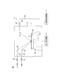
- FIG. 1 is a schematic diagram showing a configuration of a substrate processing system according to an embodiment of the present invention.
- FIG. 2 is a schematic view of the inside of the processing unit provided in the substrate processing system as viewed in the horizontal direction.
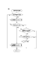
- FIG. 3 is a flowchart showing discharge stop control executed in the substrate processing apparatus.
- FIG. 4 is a flowchart showing the discharge stop control executed in the organic solvent supply apparatus.
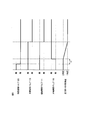
- FIG. 5 is a time chart showing the open / close state of the organic solvent valve, the common open / close valve, the individual open / close valve and the atmospheric open / close valve in the discharge stop control in the substrate processing system, and the measured value of the pressure gauge.
- FIG. 1 is a schematic diagram showing a configuration of a substrate processing system according to an embodiment of the present invention.
- FIG. 2 is a schematic view of the inside of the processing unit provided in the substrate processing system as viewed in the horizontal direction.
- FIG. 3 is a flowchart showing discharge stop control executed in the substrate processing apparatus.
- FIG. 6 is a diagram showing a depressurization state from the start of air release to the air release inside the organic solvent tank.
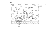
- FIG. 7 is a diagram showing the behavior of minute foreign substances contained in a liquid film of an organic solvent on the surface of a substrate.
- FIG. 8 is a schematic diagram showing a configuration of a substrate processing system according to another embodiment.
- FIG. 9 is a diagram showing a modification of the present invention.
- FIG. 1 is a schematic view of a substrate processing system 1 according to an embodiment of the present invention viewed in the horizontal direction.
- the substrate processing system 1 is a single wafer type system that processes semiconductor wafers as an example of the substrate W one by one.
- the substrate processing system 1 includes a processing unit 2 that processes a substrate W, and an organic solvent supply device 3 as a processing liquid supply device that supplies an organic solvent as an example of a processing liquid to the processing unit 2.
- the processing unit 2 and the organic solvent supply device 3 are units independent from each other (units that can be moved independently from each other). That is, as shown in FIG. 1, the substrate processing system 1 shows an example including a substrate processing apparatus 4 including a processing unit 2 and an organic solvent supply device 3 arranged at a position away from the substrate processing apparatus 4. Yes.
- the substrate processing apparatus 4 is installed in a clean room, while the organic solvent supply apparatus 3 is installed in a down space (for example, an underground floor) of a clean room called a sub-fab.
- the substrate processing system 1 includes a first control device 5 that controls opening and closing of devices and valves provided in the substrate processing device 4 and a second control device that controls opening and closing of devices and valves provided in the organic solvent supply device 3. And a control device 6.
- the processing unit 2 may be a single-wafer type unit that processes the substrates W one by one, or may be a batch type unit that processes a plurality of substrates W at once.
- FIG. 1 shows an example in which the processing unit 2 is a single-wafer type unit. In FIG. 1, only one organic solvent supply device 3 is shown. However, when a plurality of types of organic solvents are provided, the number of organic solvent supply devices 3 corresponding to the liquid type may be provided.
- the processing unit 2 includes a box-shaped processing chamber 7 having an internal space, and an organic solvent nozzle (see FIG. 2) for supplying an organic solvent to a substrate W (see FIG. 2) held in a horizontal posture in the processing chamber 7. Discharge part) 8.
- a plurality of processing units 2 are provided. As shown in FIG. 1, the plurality of processing units are arranged, for example, in a three-story structure. Although not shown in FIG. 1, for example, four processing units are arranged on each floor portion.
- the processing unit 2 is an example in which the organic solvent supply device 3 corresponds to all twelve processing units 2 and supplies chemical solutions to all the processing units 2. 3 may correspond to each part of the processing units 2 (for example, each of the three processing units 2 stacked in the vertical direction) and supply the chemical solution to the part of the processing units 2.
- the organic solvent supply device 3 includes a plurality (for example, two in FIG. 1) of organic solvent tanks (treatment liquid tanks) 9 for storing the organic solvent, and organic solvent individual pipes (individual pipes) connected to the organic solvent tanks 9. 10 and a plurality of (for example, two in FIG. 1) organic solvent individual pipes 10 and an organic solvent common pipe (common pipe) 11 that connects the processing unit 2 side.
- the organic solvent stored in the organic solvent tank 9 is, for example, IPA (isopropyl alcohol).
- Each organic solvent individual pipe 10 is provided with an individual open / close valve (open / close unit) 14 for opening and closing the organic solvent individual pipe 10.
- the organic solvent common pipe 11 includes a flow meter 12 for measuring the flow rate of the organic solvent flowing through the organic solvent common pipe 11 and a common open / close valve (open / close unit) 13 for opening and closing the organic solvent common pipe 11. It is interposed in this order from the tank 9 side.
- the organic solvent individual pipe 10 and the organic solvent common pipe 11 are formed using a resin having chemical resistance such as PFA (perfluoro-alkylvinyl-ether-tetrafluoro-ethlene-copolymer).
- PFA perfluoro-alkylvinyl-ether-tetrafluoro-ethlene-copolymer
- the organic solvent supply device 3 is a pressure supply type liquid supply device. Therefore, the organic solvent supply device 3 includes a pressure unit 15 that moves the organic solvent in the organic solvent tank 9 to the organic solvent common pipe 11 via the organic solvent individual pipe 10, and the pressure inside the organic solvent tank 9.
- a pressure gauge 16 for measurement, a new liquid supply unit (not shown) for supplying a new liquid of the organic solvent from the organic solvent supply source to the organic solvent tank 9, and the inside of the organic solvent tank 9 are stored.
- a liquid amount sensor (not shown) for detecting a liquid amount (for example, a liquid level) is further provided.
- One pressurization unit 15, pressure gauge 16, new liquid supply unit, and liquid amount sensor are provided for each organic solvent tank 9. Since IPA is a flammable liquid, it is necessary to take an explosion-proof measure when adopting the pumping system.
- the organic solvent supply apparatus 3 employs a pressure-feeding system.
- the organic solvent supply device 3 further includes an atmospheric communication pipe 17 that communicates the inside of the organic solvent tank 9 and the atmosphere, and an atmospheric opening / closing valve (pressure adjustment unit) 18 that opens and closes each atmospheric communication pipe 17.
- the atmosphere communication pipe 17 and the atmosphere opening / closing valve 18 are provided for each organic solvent tank 9.
- the atmosphere communication pipe 17 is provided with a fixed orifice (orifice) 19 on the downstream side (atmosphere side) of the atmosphere opening / closing valve 18.
- Each pressurization unit 15 includes a pressurization gas pipe 20 through which a high-pressure gas for pressurization (for example, an inert gas such as nitrogen gas) flows, and a pressurization valve 21 that opens and closes the pressurization gas pipe 20.
- a high-pressure gas for pressurization for example, an inert gas such as nitrogen gas
- a pressurization valve 21 that opens and closes the pressurization gas pipe 20.
- Each organic solvent tank 9 is partitioned into a container shape by a partition wall.
- the partition walls of the organic solvent tank 9 are made of, for example, stainless steel, and the entire inner surface thereof is coated with PTFE (polytetrafluoroethylene).
- the capacity of each organic solvent tank 9 is several to several tens of liters.
- the processing unit 2 side is supplied with an organic solvent from one organic solvent tank 9 selected from the plurality of organic solvent tanks 9.
- the supply source of the organic solvent is switched to the other organic solvent tank 9 and stored in the other organic solvent tank 9.
- An organic solvent is supplied to the processing unit 2 side.
- the organic solvent tank 9 (one organic solvent tank 9) which has been emptied can be supplied with a new liquid of the organic solvent from a new liquid supply unit (not shown).
- a new liquid supply unit not shown.
- the atmospheric on-off valve 18 corresponding to one organic solvent tank 9 is opened, and the one organic solvent By depressurizing the inside of the tank 9 from the high pressure state to the atmospheric pressure, it becomes possible to supply a new organic solvent solution to the organic solvent tank 9.
- Switching of the organic solvent supply source is performed by opening and closing the individual opening / closing valve 14 provided in each organic solvent individual pipe 10. That is, the individual opening / closing valve 14 functions as a switching valve for switching the supply source organic solvent tank 9.
- the second control device 6 is configured using, for example, a microcomputer.
- the second control device 6 includes an arithmetic unit such as a CPU, a fixed memory device, a storage unit such as a hard disk drive, and an input / output unit.
- the storage unit stores a program executed by the arithmetic unit.
- the second control device 6 opens and closes the common open / close valve 13, the individual open / close valve 14, the atmospheric open / close valve 18, the pressurizing valve 21 and the like according to a program predetermined in the storage unit. Further, detection outputs of the flow meter 12 and the pressure gauge 16 are input to the second control device 6.
- the second controller 6 closes the individual opening / closing valve 14 corresponding to the other organic solvent tank 9. Then, the individual opening / closing valve 14 corresponding to one organic solvent tank 9 is opened, and the common opening / closing valve 13 is opened. Further, the second control device 6 opens the pressurizing valve 21 corresponding to one organic solvent tank 9. As a result, a high-pressure gas is supplied to one organic solvent tank 9, and the organic solvent stored in one organic solvent tank 9 is supplied to the corresponding organic solvent individual pipe 10 by the supply pressure (nitrogen pressure) at this time. And is moved to the organic solvent common pipe 11 through the organic solvent individual pipe 10. Thereby, the organic solvent is supplied from the organic solvent supply device 3 toward the processing unit 2. In this organic solvent supply state, the pressure inside the one organic solvent tank 9 and the pressure inside the pipes 10 and 11 corresponding to the one organic solvent tank 9 are kept at a high pressure (for example, about 2 atmospheres). Yes.
- the second controller 6 When supplying the organic solvent stored in the other organic solvent tank 9 to the processing unit 2 side, the second controller 6 closes the individual opening / closing valve 14 corresponding to the one organic solvent tank 9. In this state, the individual opening / closing valve 14 corresponding to the other organic solvent tank 9 is opened, and the common opening / closing valve 13 is opened.
- the second control device 6 opens the pressurizing valve 21 corresponding to the other organic solvent tank 9. Thereby, a high-pressure gas is supplied to the other organic solvent tank 9, and the organic solvent stored in the other organic solvent tank 9 is supplied to the corresponding organic solvent individual pipe 10 by the supply pressure (nitrogen pressure) at this time. And is moved to the organic solvent common pipe 11 through the organic solvent individual pipe 10.
- the organic solvent is supplied from the organic solvent supply device 3 toward the processing unit 2 side.
- the pressure inside the other organic solvent tank 9 and the pressure inside the pipes 10 and 11 corresponding to the other organic solvent tank 9 are kept at a high pressure (for example, about 2 atmospheres). Yes.
- the organic solvent tank 9 that is supplying the organic solvent to the processing unit 2 side is referred to as a “current organic solvent tank 9”.
- the organic solvent nozzle 8 included in each processing unit 2 is supplied with the organic solvent from the organic solvent supply device 3 through a processing side pipe (second processing liquid pipe) 22 that passes through the substrate processing apparatus 4.
- the processing side pipe 22 includes a processing side common pipe 23 connected to the organic solvent common pipe 11 and a processing side branch pipe 24 that connects each organic solvent nozzle 8 and the processing side common pipe 23.
- An organic solvent valve 25 for opening and closing the processing side branch pipe 24 is interposed in the processing side branch pipe 24.
- the second control device 6 opens the organic solvent valve 25, whereby the organic solvent nozzle 8 included in each processing unit 2. Is supplied with an organic solvent.
- the processing side common pipe 23 and the processing side branch pipe 24 are formed using a resin having chemical resistance such as PFA (perfluoro-alkylvinyl-ether-tetrafluoro-ethlene-copolymer).
- FIG. 2 is a schematic view of the inside of the processing unit 2 viewed in the horizontal direction.
- the processing unit 2 holds a single substrate W in a horizontal posture in the processing chamber 7, and rotates the substrate W around a vertical rotation axis passing through the center of the substrate W. It further includes a chemical nozzle 27 for supplying chemical liquid to the substrate W held, and a rinsing liquid nozzle 28 for supplying rinsing liquid to the substrate W held by the spin chuck 26.
- the spin chuck 26 has a disk-like spin base 29 that can hold the substrate W substantially horizontally and can rotate about the vertical axis, and a rotary drive unit 30 such as a motor that rotates the spin base 29 about the vertical axis.
- the chemical nozzle 27 and the rinsing liquid nozzle 28 may be fixed nozzles where the liquid and rinsing liquid landing positions are fixed on the substrate W, respectively. It may be a scan nozzle that moves in the range from the center of rotation to the periphery of the substrate W.
- the chemical solution nozzle 27 is connected to a chemical solution pipe 32 in which a chemical solution valve 31 is interposed.
- a chemical solution is supplied to the chemical solution nozzle 27.
- the chemical liquid supplied to the chemical nozzle 27 is, for example, sulfuric acid, acetic acid, nitric acid, hydrochloric acid, hydrofluoric acid, aqueous ammonia, hydrogen peroxide, organic acid (for example, citric acid, oxalic acid, etc.), organic alkali (for example, TMAH: tetra Methylammonium hydroxide and the like, and at least one of a surfactant and a corrosion inhibitor.
- the rinse liquid nozzle 28 is connected to a rinse liquid pipe 34 in which a rinse liquid valve 33 is interposed.
- the rinse liquid nozzle 28 is supplied with pure water (deionized water) which is an example of a rinse liquid.
- the rinsing liquid supplied to the rinsing liquid nozzle 28 is not limited to pure water but may be any of carbonated water, electrolytic ion water, hydrogen water, ozone water, and hydrochloric acid water having a diluted concentration (for example, about 10 to 100 ppm). May be.
- the first control device 5 is configured using a computer, for example.
- the first control device 5 includes an arithmetic unit such as a CPU, a fixed memory device, a storage unit such as a hard disk drive, and an input / output unit.
- the storage unit stores a program executed by the arithmetic unit.
- the first control device 5 controls the operation of the rotary drive unit 30 and the like according to a program predetermined in the storage unit. Further, the first control device 5 controls the opening / closing operation of the organic solvent valve 25, the chemical liquid valve 31, the rinse liquid valve 33, and the like.
- the first control device 5 (substrate processing device 4) is provided so as to be able to communicate with the second control device 6 (organic solvent supply device 3).
- the first control device 5 transmits a supply request signal to the organic solvent supply device 3.
- the second control device 6 opens the individual open / close valve 14 corresponding to the current organic solvent tank 9, opens the common open / close valve 13, and the current organic solvent.
- the pressurizing valve 21 corresponding to the tank 9 is opened.
- the organic solvent can be supplied from the organic solvent supply device 3 to the processing unit 2 via the organic solvent common pipe 11.
- the current pressure inside the organic solvent tank 9 and the pressure inside the pipes 10 and 11 corresponding to the organic solvent tank 9 are high (for example, 2 atmospheres). Degree).
- the first control device 5 when processing using a processing liquid (chemical solution, rinsing liquid, and organic solvent) is performed on the substrate W in the processing unit 2, the first control device 5 causes the substrate W The substrate W is rotated around the vertical axis while holding the substrate horizontally. In this state, the first control device 5 opens the chemical liquid valve 31 and discharges the chemical liquid from the chemical liquid nozzle 27 toward the upper surface of the substrate W. The chemical solution supplied to the substrate W spreads outward on the substrate W due to the centrifugal force generated by the rotation of the substrate W, and is discharged from the periphery of the upper surface of the substrate W to the periphery of the substrate W.
- a processing liquid chemical solution, rinsing liquid, and organic solvent
- the first control device 5 stops the discharge of the chemical solution from the chemical solution nozzle 27 and then opens the rinse solution valve 33 to discharge the rinse solution from the rinse solution nozzle 28 toward the upper surface of the rotating substrate W. Let Thereby, the chemical on the substrate W is washed away by the rinse liquid.
- the first control device 5 stops the discharge of the rinsing liquid from the rinsing liquid nozzle 28 and then opens the organic solvent valve 25 to open the organic solvent from the organic solvent nozzle 8 toward the upper surface of the rotating substrate W. To discharge. Thereby, the rinse liquid on the substrate W is replaced with the organic solvent.
- the first controller 5 dries the substrate W by rotating the substrate W at a high speed by the spin chuck 26. In this way, a series of processes are performed on the substrate W.
- FIG. 3 is a flowchart showing the discharge stop control executed in the substrate processing apparatus 4.
- FIG. 4 is a flowchart showing the discharge stop control executed in the organic solvent supply device 3.
- FIG. 5 is a time chart showing the open / close state of the organic solvent valve 25, the common open / close valve 13, the individual open / close valve 14 and the atmospheric open / close valve 18, and the measured value of the pressure gauge 16 in the discharge stop control in the substrate processing system 1.
- FIG. 6 is a diagram showing a depressurization state from the start of the atmosphere release to the atmosphere release inside the organic solvent tank 9.
- the first control device 5 opens the organic solvent valve 25. Thereby, the organic solvent is discharged from the organic solvent nozzle 8.
- the first controller 5 closes the organic solvent valve 25 (step S2 in FIG. 3).
- the first control device 5 determines that the substrate processing device 4 is in an organic solvent supply unnecessary state (YES in step S3 in FIG. 3)
- the first control device 5 detects the organic solvent supply device 3. A supply unnecessary signal is transmitted to (step S4 in FIG. 3). Further, when it is not the discharge stop timing (NO in step S1 in FIG. 3), when it is determined that the organic solvent supply is not required (NO in step S3 in FIG. 3), and after the supply unnecessary signal is transmitted, the processing shown in FIG. Will be returned.
- the organic solvent supply unnecessary state refers to a state in which the substrate processing apparatus 4 does not require any more organic solvent supply.
- a state in which the discharge of the organic solvent of the other processing unit 2 has been completed at the end of the discharge of the organic solvent of one processing unit 2 is an example of the state in which the organic solvent supply is unnecessary.
- the processing unit 2 included in the substrate processing apparatus 4 has no plan to discharge the organic solvent for a while after that as a condition for establishing the organic solvent supply unnecessary state. You may make it add.
- the second control apparatus 6 opens the atmospheric opening / closing valve 18 corresponding to the current organic solvent tank 9 (step in FIG. 4). T2).
- the inside of the organic solvent tank 9 is depressurized by opening the air opening / closing valve 18.
- the fixed orifice 19 is provided in the atmosphere communication pipe 17, it is difficult for gas to pass through the atmosphere communication pipe 17. Therefore, even if the atmosphere communication pipe 17 is opened, the inside of the organic solvent tank 9 is not depressurized at once, but the internal pressure gradually decreases over a certain period of time. That is, it takes a certain amount of time from the start of air release inside the organic solvent tank 9 until the internal pressure drops to atmospheric pressure.
- a predetermined delay D exists between the closing of the organic solvent valve 25 and the opening of the atmospheric opening / closing valve 18.
- the second control device 6 refers to the detection output of the pressure gauge 16 corresponding to the current organic solvent tank 9 and checks whether or not the current inside of the organic solvent tank 9 is depressurized to atmospheric pressure ( Step T3 in FIG. Then, when the current pressure inside the organic solvent tank 9 is reduced to atmospheric pressure (YES in step T3 in FIG. 4), the second control device 6 closes the common opening / closing valve 13 and the individual opening / closing valve 14 ( Step T4 in FIG. Therefore, after the valves 13 and 14 are closed, the inside of the organic solvent tank 9, the inside of the organic solvent individual pipe 10, and the inside of the organic solvent common pipe 11 are maintained at atmospheric pressure.
- the solubility of a gas in a liquid is proportional to its pressure, the gas does not dissolve so much in a liquid at atmospheric pressure. Therefore, the amount of dissolved gas in the organic solvent in the organic solvent tank 9, the organic solvent individual pipe 10, and the organic solvent common pipe 11 can be reduced.
- the second control device 6 opens the atmospheric opening / closing valve 18 (that is, the atmospheric release). ) To determine whether or not a predetermined time (X seconds (for example, about 5 seconds)) has elapsed (step T5 in FIG. 4). Then, when X seconds have elapsed since the opening of the air opening / closing valve 18 (YES in step T5 in FIG. 4), the second control device 6 refers to the detection output of the pressure gauge 16 corresponding to the current organic solvent tank 9 ( Step T6 in FIG.
- X seconds for example, about 5 seconds
- the second control device 6 is in an error state. It is judged that.
- the second control device 6 includes a memory (not shown). This memory stores a threshold value of the pressure value. As shown in FIG. 6, the threshold value is a lower limit pressure value after X seconds from the start of the atmospheric release, and when the measured value is less than the threshold value, the pressure reduction rate inside the organic solvent tank 9 is too high. Therefore, it is determined that there is an error state because of sudden pressure reduction.
- the broken line shown in FIG. 6 is an error state.
- the two-dot chain line shown in FIG. 6 is in an error-free state (OK state). If the pressure reduction speed inside the organic solvent tank 9 is too high, the gas dissolved in the organic solvent may appear as bubbles (microbubbles) during the pressure reduction process. For this reason, the second control device 6 detects an error state when the pressure reduction speed inside the organic solvent tank 9 is higher than a predetermined speed.
- the second control device 6 When determining that the second control device 6 is in an error state, the second control device 6 performs a predetermined error process (step T7 in FIG. 4). Examples of error processing include recording the occurrence of an error state in a log file and outputting an alarm from the substrate processing apparatus 4 or the organic solvent supply apparatus 3.
- step T5 in FIG. 4 If the supply unnecessary signal has not been received (NO in step T1 in FIG. 4), or if X seconds have not elapsed since the opening of the air opening / closing valve 18 (NO in step T5 in FIG. 4), the measured value is equal to or greater than the threshold value. 4 (YES in step T5 in FIG. 4), the processing shown in FIG. 4 is returned after the valves 13 and 14 are closed and the error processing is completed.
- FIG. 7 is a diagram showing the behavior of the minute foreign matter 42 contained in the liquid film 41 of the organic solvent on the surface of the substrate W.
- the organic solvent discharged from the organic solvent nozzle 8 may contain bubbles 43. If the bubbles 43 are contained in the liquid film 41 of the organic solvent, a gas-liquid interface is formed by the liquid of the organic solvent and the bubbles 43. The minute foreign matter 42 contained in the organic solvent is attracted to and gathers at the gas-liquid interface, and grows into a minute particle of a predetermined size. As a result, fine particles may be generated on the surface of the substrate W after drying. If the amount of bubbles contained in the organic solvent liquid film 41 is large, the gas-liquid interface may become large, and the problem of generation of microparticles may become apparent.
- the installation location of the organic solvent supply device 3 is downstairs of the substrate processing device 4 (downstairs installation).
- the valves 13 and 14 are disposed below the organic solvent valve 25.
- the problem of bubble generation may become more apparent.
- the length of the organic solvent common pipe 11 is long (for example, 5 to 10 m). Therefore, there is a local high-pressure portion inside the organic solvent common pipe 11, which may further cause the above-described problem of bubble generation.
- FIG. 8 is a schematic diagram showing a configuration of a substrate processing system according to another embodiment.
- portions corresponding to the respective portions shown in the embodiment of the present invention are denoted by the same reference numerals as in FIGS. 1 to 6, and description thereof is omitted.
- the substrate processing system includes an organic solvent supply device 103 and a third control device 106 that controls the organic solvent supply device 103.
- the third control device 106 is configured by a computer.
- the organic solvent supply device 103 is different from the organic solvent supply device 3 described above in that the atmospheric communication pipe 17 (see FIG. 1), the atmospheric opening / closing valve 18 (see FIG. 1) and the pressure gauge 16 (see FIG. 1) are eliminated. This is the point.
- Other configurations are the same as those of the organic solvent supply device 3 described above.
- the third control device 106 when the supply unnecessary signal from the substrate processing device 4 is received (when the organic solvent valve 25 is closed), the third control device 106 then opens the common open / close valve 13 and the individual open / close valve.
- the valve 14 is closed.
- the current organic solvent tank 9 and the pipes 10 and 11 corresponding to the organic solvent tank 9 hereinafter referred to as “tanks etc. 9, 10, 11”).
- the common open / close valve 13 and the individual open / close valve 14 are closed without releasing the pressure inside the tank 9, 10, 11, the internal pressure of the tank 9, 10, 11 after the valves 13, 14 are closed. Remains at high pressure.
- a large amount of gas (inert such as nitrogen gas) dissolves in the organic solvent inside the tanks 9, 10, and 11 to keep pushing with the high-pressure pressurized gas.
- the atmosphere (for example, oxygen) outside the pipes 10 and 11 may permeate through the pipe walls of the pipes 10 and 11 made of PFA and dissolve in an organic solvent existing in a liquid-tight state inside the pipes 10 and 11. is there.
- a large amount of atmosphere (for example, oxygen) may be dissolved in the organic solvent inside the pipes 10 and 11 in a high pressure state.
- the amount of bubbles contained in the organic solvent discharged onto the substrate W may increase.
- the organic solvent nozzle 8 is used when the organic solvent is re-discharged in the processing unit 2.
- the organic solvent valve 25 is opened to discharge the organic solvent from the organic solvent, the organic solvent that has been kept at a high pressure until then (especially, the organic solvent in the organic solvent common pipe 11) is suddenly reduced in pressure and dissolved therein. There is a possibility that the gas that has been turned into bubbles and foams in large quantities.
- the third control device 106 controls the common opening / closing valve 13 and the individual opening / closing valve 14.
- the atmosphere communication pipe 17 is opened, the inside of the organic solvent tank 9 in a pressurized state is gradually released to the atmosphere, and the common opening and closing is performed after the pressure inside the organic solvent tank 9 drops to atmospheric pressure.
- the valve 13 and the individual opening / closing valve 14 are closed. Therefore, after the valves 13 and 14 are closed, the inside of the organic solvent tank 9, the inside of the organic solvent individual pipe 10, and the inside of the organic solvent common pipe 11 are maintained at atmospheric pressure.
- the amount of gas dissolved in the liquid at atmospheric pressure is small. Therefore, the amount of dissolved gas in the organic solvent in the organic solvent tank 9, the organic solvent individual pipe 10, and the organic solvent common pipe 11 can be reduced. Since the amount of gas dissolved in the organic solvent is small, the amount of bubbles generated in the organic solvent can be reduced.
- the organic solvent when the organic solvent is re-discharged in the processing unit 2, the inside of the organic solvent individual pipe 10 and the inside of the organic solvent common pipe 11 are maintained in a pressurized state, and the organic solvent valve 25 is opened in this state. It is. At the time of this re-discharge, the decompression occurs in the pipes 10 and 11 with the opening of the organic solvent valve 25. However, since the amount of dissolved gas in the organic solvent inside the pipes 10 and 11 is small, the decompression is accompanied. Thus, the amount of bubbles generated in the organic solvent can be reduced.
- the amount of bubbles contained in the organic solvent supplied from the organic solvent supply device 3 to the processing unit 2 can be reduced.
- the organic solvent tank 9 is determined based on the measurement value of the pressure gauge 16. It may be determined that the internal pressure of the organic solvent tank 9 has decreased to atmospheric pressure by detecting that the internal pressure of the organic solvent tank has decreased to a predetermined pressure and that a predetermined time has elapsed after the detection.
- the common opening / closing valve 13 and the individual opening / closing valve 14 are closed after the pressure inside the organic solvent tank 9 is reduced to atmospheric pressure.
- the common opening / closing valve 13 and the individual opening / closing valve 14 may be closed.
- the fixed orifice 19 is described as being provided in the atmosphere communication pipe 17 separately from the atmosphere opening / closing valve 18, the orifice opening / closing valve 18 itself may be provided with an orifice. That is, a valve with an orifice may be provided as the air opening / closing valve 18.
- an opening adjustment unit 218 for adjusting the opening of the atmosphere communication pipe 17 may be provided instead of the fixed orifice 19.
- the opening degree adjusting unit 218 may be a flow rate adjusting valve as shown in FIG. 9 or a variable orifice (flow rate adjusting orifice).
- the flow rate adjusting valve includes a valve body in which a valve seat is provided, a valve body that opens and closes the valve seat, and an actuator that moves the valve body between an open position and a closed position.
- An electric motor, an air cylinder, or the like can be employed as the actuator.
- various types, such as a needle valve, a diaphragm valve, and a butterfly valve can be adopted as the flow rate adjusting valve.
- the opening degree adjusting unit 218 may be used together with the atmospheric opening / closing valve 18, or when the opening degree adjusting unit 218 has an opening / closing function, the atmospheric opening / closing valve 18 may be eliminated. .
- the fixed orifice 19 and the opening degree adjusting unit 218 may not be provided.
- the second control device 6 may realize that the inside of the organic solvent tank 9 is gradually released to the atmosphere by lowering the opening speed of the atmosphere opening / closing valve 18.
- the pressure adjustment unit for adjusting the pressure inside the organic solvent tank 9 does not need to be provided in the atmosphere communication pipe 17.
- the pressure adjustment unit may be provided directly in the organic solvent tank 9, for example.
- the organic solvent supply device 3 includes a plurality of organic solvent tanks 9 has been described as an example.
- the organic solvent supply device 3 includes only one organic solvent tank 9. May be.
- the organic solvent individual piping 10 and the individual opening / closing valve 14 can be eliminated.
- the organic solvent supply device 3 may include not only a mechanism for supplying an organic solvent but also a mechanism for supplying another chemical solution.
- the configuration may be shared with other chemical solution supply apparatuses.
- IPA has been described as an example of the organic solvent supplied from the organic solvent supply device 3, but in addition to IPA, methanol, ethanol, acetone, HFE (hydrofluoroether), and EG (ethylene) are used.
- An organic solvent such as glycol can be used.
- the processing unit 2 and the organic solvent supply device 3 are described as units independent from each other.
- the processing unit 2 and the organic solvent supply device 3 may be part of a common device.
- the substrate processing system may include a substrate processing apparatus including the processing unit 2 and the organic solvent supply device 3.
- a control device in which the first and second control devices 5 and 6 are integrated may be used.
- processing liquid supply device has been described by taking the organic solvent supply device 3 that supplies an organic solvent as an example, but the processing liquid supply device is not limited to the one that supplies an organic solvent, and supplies a chemical solution, a rinse solution, or the like. You may do.
- the semiconductor wafer is taken up as the substrate W to be processed.
- the semiconductor wafer is not limited to the semiconductor wafer.
- a glass substrate for a liquid crystal display device a plasma display substrate, an FED substrate, an optical disk substrate, Other types of substrates such as a magnetic disk substrate, a magneto-optical disk substrate, a photomask substrate, a ceramic substrate, and a solar cell substrate may be processed.
- substrate processing system 2 processing unit 3: organic solvent supply device (processing liquid supply device) 4: Substrate processing device 6: Second control device 8: Organic solvent nozzle (discharge unit) 9: Organic solvent tank (treatment liquid tank) 10: Organic solvent individual piping (individual piping) 11: Organic solvent common piping (common piping) 13: Common open / close valve 14: Individual open / close valve 15: Pressurizing unit 16: Pressure gauge 17: Atmospheric communication pipe 18: Atmospheric open / close valve 19: Fixed orifice (orifice) 22: Processing side piping (second processing liquid piping) W: Substrate
Landscapes
- Cleaning Or Drying Semiconductors (AREA)
- Cleaning By Liquid Or Steam (AREA)
- Application Of Or Painting With Fluid Materials (AREA)
- Coating Apparatus (AREA)
Abstract
処理液供給装置は、処理液を貯留する処理液タンクと、前記処理ユニットと前記処理液タンクとを接続する第1の処理液配管と、前記第1の処理液配管を開閉するための開閉ユニットと、前記処理液タンクの内部の処理液を前記第1の処理液配管の内部に送り出すべく、当該処理液を気体で加圧する加圧ユニットと、前記処理液タンクの内部の圧力を調整するための圧力調整ユニットと、前記開閉ユニットの閉成に先立って前記圧力調整ユニットを制御して、加圧状態にある前記処理液タンクの内部を徐々に大気解放させ、当該大気開放開始後に前記開閉ユニットを閉じる制御装置とを含む。
Description
本発明は、処理液を供給する処理液供給装置、それを備えた基板処理システム、および処理液を供給する処理液供給方法に関する。処理液を用いた処理の対象となる基板には、たとえば、半導体ウエハ、液晶表示装置用基板、プラズマディスプレイ用基板、FED(Field Emission Display)用基板、光ディスク用基板、磁気ディスク用基板、光磁気ディスク用基板、フォトマスク用基板、セラミック基板、太陽電池用基板などが含まれる。
下記特許文献1には、基板処理部に処理液を供給する処理液供給装置が開示されている。前記処理液供給装置は、処理液を貯留する処理液タンクと、処理液タンクと基板処理部とを接続する処理液配管と、処理液配管を開閉するためのバルブとを含む。前記処理液供給装置は、いわゆる加圧圧送方式を採用しており、処理液タンクの内部の処理液を気体で加圧することにより、当該処理液を処理液配管に移動させる加圧ユニットをさらに含む。
このような処理液供給装置では、基板処理部側から供給不要が通知されると、処理液タンクおよび処理液配管の内部が加圧された状態のまま、基板処理部側のバルブが閉じられる。そのため、バルブの閉成以降は、処理液タンクおよび処理液配管の内部の圧力が加圧された状態に保たれたままである。
高圧の加圧気体で押し続けるために、処理液タンクおよび処理液配管の内部の処理液に多量の気体(窒素ガス等の不活性)が溶け込む。液体に対する気体の溶解度はその圧力に比例するので、高圧状態にある処理液配管の内部では、処理液に気体が多量に溶け込むおそれもある。
基板に供給される処理液(例えば有機溶剤などが挙げられる)中に気泡が含まれていると、処理液の液体と気泡とによって形成される気液界面に、処理液に含まれる微小の異物が引き付けられて集まり、パーティクルに成長する。その結果、乾燥後の基板の表面にパーティクルが発生するおそれがある。そして、処理液中に含まれる気泡量が多いと、気液界面が大面積化してパーティクルの発生の問題が顕在化するおそれがある。
このような問題は、有機溶剤を基板に供給する場合だけでなく、他の種類の処理液を基板に供給する場合にも共通する問題である。
そこで、本発明の一の目的は、供給する処理液に含まれる気泡量を低減できる処理液供給装置および処理液供給方法を提供することである。
また、本発明の他の目的は、パーティクルの発生を抑制または防止できる基板処理システムを提供することである。
この発明は、処理液を用いた処理を基板に施す処理ユニットに対して処理液を供給する処理液供給装置であって、処理液を貯留する処理液タンクと、前記処理ユニットと前記処理液タンクとを接続する第1の処理液配管と、前記第1の処理液配管を開閉するための開閉ユニットと、前記処理液タンクの内部の処理液を気体で加圧することにより、当該処理液を前記第1の処理液配管に移動させる加圧ユニットと、前記処理液タンクの内部の圧力を調整するための圧力調整ユニットと、前記処理液供給装置から前記処理ユニットへの処理液の供給を停止するために、前記開閉ユニットの閉成に先立って前記圧力調整ユニットを制御して、加圧状態にある前記処理液タンクの内部を徐々に大気解放させ、当該大気開放開始後に前記開閉ユニットを閉じる制御装置とを含む、処理液供給装置を提供する。
この構成によれば、処理液供給装置から処理ユニットへの処理液の供給停止の際には、制御装置は、開閉ユニットの閉成に先立って、加圧ユニットによる加圧状態にある処理液タンクの内部を徐々に大気解放させ、大気開放開始後に前記開閉ユニットを閉じる。処理液タンクの内部の減圧開始後に開閉ユニットを閉じるため、それ以降は、処理液タンクの内部および第1の処理液配管の内部が、前記の加圧状態よりも減圧された状態に維持される。液体に対する気体の溶解度はその圧力に比例するため、当該減圧状態にある処理液配管の内部に気体はそれほど溶け込まない。処理液の溶存気体量が少ないから、処理液に発生する気泡量を低減できる。
また、処理液タンクの内部の大気解放を徐々に行うため、処理液に溶け込んでいる気体が、その減圧過程で気泡として出現することも抑制または防止できる。
以上により、供給する処理液に含まれる気泡量を低減できる処理液供給装置を提供できる。
この発明の一実施形態では、前記制御装置は、前記処理液タンクの内部の圧力が大気圧まで下がった後に、前記開閉ユニットを閉じる。
この構成によれば、処理液タンクの内部の圧力が大気圧まで下がった後に開閉ユニットを閉じるので、それ以降は、処理液タンクの内部および第1の処理液配管の内部が大気圧に維持される。そのため、処理液タンクの内部および第1の処理液配管の内部の処理液への溶存気体量を、より一層低減できる。ゆえに、処理液に含まれる気泡量をより一層低減できる。
前記処理液供給装置は前記処理液タンクの内部の圧力を検出するための圧力計をさらに含み、前記制御装置は、前記大気開放開始から所定時間が経過した時点における、前記圧力計の検出値が所定の閾値未満である場合にエラー状態であると判断してもよい。
この構成によれば、大気開放開始から所定時間が経過した時点における圧力値が所定の閾値未満である場合にはエラー状態であると判断する。これにより、処理液タンクの内部の減圧速度が速過ぎることを防止でき、ゆえに、処理液に含まれる気泡量をより効果的に低減できる。
前記処理液装置は前記処理液タンクの内部と大気とを連通する大気連通配管をさらに含み、前記圧力調整ユニットは、前記大気連通配管を開閉するための大気開閉バルブを含んでいてもよい。
この構成によれば、大気開閉バルブを開いて大気連通配管を開くことにより、処理液タンクの内部を大気解放させることができる。したがって、処理液タンクの内部を大気解放させることが可能な構成を、簡単な構造で実現できる。
前記大気連通配管にはオリフィスが設けられていてもよい。この場合、オリフィスが大気連通配管に設けられているために、大気連通配管の内部を気体が通過し難い。そのため、大気連通配管を開いても、処理液タンクの内部が一気に減圧されるのではなく、当該内部の圧力がある程度の時間を掛けて徐々に低下する。したがって、処理液タンクの内部を徐々に大気解放させることが可能な構成を、簡単な構造で実現できる。
前記処理液装置は前記処理液タンクの内部と大気とを連通する大気連通配管をさらに含み、前記圧力調整ユニットは、前記大気連通配管の開度を調整する開度調整ユニットを含んでいてもよい。
この構成によれば、大気連通配管の開度を調整することにより、大気連通配管の内部の気体の通過し易さを調整できる。そのため、処理液タンクの内部の大気解放時に、大気連通配管の開度を低くすることにより、処理液タンクの内部を大気解放開始させてから当該内部が大気圧まで減圧するまでの時間を長くすることが可能である。したがって、処理液タンクの内部を徐々に大気解放させることが可能な構成を、簡単な構造で実現できる。
前記処理液タンクは複数の処理タンクを含み、前記第1の処理液配管は、各処理液タンクに接続された個別配管と、前記複数の個別配管のそれぞれと前記処理ユニットとを接続する共通配管とを含み、前記開閉ユニットは、各個別配管を開閉する個別開閉バルブと、前記共通配管を開閉する共通開閉バルブとを含んでいてもよい。
この構成によれば、処理液供給装置から処理ユニットへの処理液の供給停止の際に、制御装置は、共通開閉バルブおよび個別開閉バルブの閉成に先立って、加圧状態にある処理液タンクの内部を徐々に大気解放させ、大気開放開始後に開閉ユニットを閉じる。これにより、処理液タンクを複数設ける場合であっても、処理液に発生する気泡量を低減できる。
前記処理液タンクに貯留される処理液は、有機溶剤を含んでいてもよい。
処理液として有機溶剤を用いる場合、有機溶剤は、その大半が引火性液体であり、そのため、有機溶剤をポンプ圧送方式により送液することはできず、前述のような加圧ユニットを用いて、処理ユニットに対する有機溶剤の送液が行われる(加圧圧送方式)。この場合、処理液供給装置が供給する有機溶剤に含まれる気泡量を低減できる。
また、この発明は、処理液を用いた処理を基板に施す処理ユニットと、前記処理液供給装置とを含む基板処理システムであって、前記処理ユニットは、前記基板に供給すべき処理液を吐出するための吐出部と、前記第1の処理液配管と前記吐出部とを接続する第2の処理液配管と、前記第2の処理液配管を開閉するための処理液バルブとを含み、前記制御装置は、前記処理液配管から前記吐出部に対する処理液の供給を停止するために、前記処理液バルブを閉じ、その後に前記圧力調整ユニットを制御して前記処理液タンクの内部を減圧させる制御装置とを含む、基板処理システムを提供する。
この構成によれば、吐出部からの処理液の吐出停止の際には、制御装置は、まず処理液バルブを閉じて処理液配管から吐出部に対する処理液の供給を停止し、次いで、処理液タンクの内部を徐々に大気解放させ、大気開放開始後に前記開閉ユニットを閉じる。
処理液タンクの内部の減圧開始後に開閉ユニットを閉じるため、それ以降は、処理液タンクの内部および第1の処理液配管の内部が、前記の加圧状態よりも減圧された状態に維持される。液体に対する気体の溶解度はその圧力に比例するため、当該減圧状態にある処理液配管の内部に気体はそれほど溶け込まない。したがって、処理液タンクの内部および第1の処理液配管の内部の処理液への溶存気体量を低減できる。処理液の溶存気体量が少ないから、処理液に発生する気泡量を低減できる。
また、処理液タンクの内部の大気解放を徐々に行うため、処理液に溶け込んでいる気体が、その減圧過程で気泡として出現することも抑制または防止できる。
以上により、処理ユニットに供給される処理液に含まれる気泡量を低減できる。これにより、基板におけるパーティクルの発生を抑制または防止できる基板処理システムを提供できる。
この発明の一実施形態では、前記処理液バルブは、前記開閉ユニットよりも上方に配置されていてもよい。この場合、開閉ユニットを処理液バルブよりも下方に配置する場合には、処理液タンクに貯留されている処理液を処理ユニットまで届かせるためには、処理液タンクの内部の処理液を、より高圧で押す必要がある。この場合、供給時における処理液タンクおよび第1の処理液配管の内部の圧力がより高くなる結果、前述の気泡の発生の問題が一層顕在化するおそれがある。
しかしながら、処理液タンクの内部を徐々に大気解放させ、大気開放開始後に、開閉ユニットを閉じるので、処理ユニットに供給される処理液に含まれる気泡量をより一層低減でき、これにより、基板におけるパーティクルの発生を、より一層抑制または防止できる。
前記処理液供給装置は、前記処理ユニットよりも階下に配置されていてもよい。
この構成によれば、処理液供給装置を階下に設置するために、第1の処理液配管の配管長が長くなる。したがって、第1の処理液配管の内部には局所的に高圧な部分が存在し、これにより、前述の気泡の発生の問題がさらに顕在化するおそれもある。
しかしながら、処理液タンクの内部を徐々に大気解放させ、大気開放開始後に、開閉ユニットを閉じるので、処理ユニットに供給される処理液に含まれる気泡量をより一層低減でき、これにより、基板におけるパーティクルの発生を、より一層抑制または防止できる。
また、この発明は、処理液を貯留する処理液タンクと、処理液を用いた処理を基板に施す処理ユニットと前記処理液タンクとを接続する第1の処理液配管と、前記第1の処理液配管を開閉するための開閉ユニットと、前記処理液タンクの内部の処理液を気体で加圧することにより、当該処理液を前記第1の処理液配管に移動させる加圧ユニットとを含む処理液供給装置において実行される処理液供給方法であって、前記処理液供給装置から前記処理ユニットへの処理液の供給を停止するために、加圧状態にある前記処理液タンクの内部を徐々に大気解放させ、当該大気開放開始後に前記開閉ユニットを閉じる、処理液供給方法を提供する。
この方法によれば、処理液供給装置から処理ユニットへの処理液の供給停止の際には、制御装置は、開閉ユニットの閉成に先立って、加圧ユニットによる加圧状態にある処理液タンクの内部を徐々に大気解放させ、大気開放開始後に前記開閉ユニットを閉じる。処理液タンクの内部の減圧開始後に開閉ユニットを閉じるため、それ以降は、処理液タンクの内部および第1の処理液配管の内部が、前記の加圧状態よりも減圧された状態に維持される。液体に対する気体の溶解度はその圧力に比例するため、当該減圧状態にある処理液配管の内部に気体はそれほど溶け込まない。したがって、処理液タンクの内部および第1の処理液配管の内部の処理液への溶存気体量を低減できる。処理液の溶存気体量が少ないから、処理液に発生する気泡量を低減できる。
また、処理液タンクの内部の大気解放を徐々に行うため、処理液に溶け込んでいる気体が、その減圧過程で気泡として出現することも抑制または防止できる。
以上により、供給する処理液に含まれる気泡量を低減できる処理液供給方法を提供できる。
本発明における前述の、またはさらに他の目的、特徴および効果は、添付図面を参照して次に述べる実施形態の説明により明らかにされる。
図1は、本発明の一実施形態に係る基板処理システム1を水平方向に見た模式図である。基板処理システム1は、基板Wの一例としての半導体ウエハを1枚ずつ処理する枚葉型のシステムである。基板処理システム1は、基板Wを処理する処理ユニット2と、この処理ユニット2に、処理液の一例としての有機溶剤を供給する処理液供給装置としての有機溶剤供給装置3とを含む。処理ユニット2および有機溶剤供給装置3は、互いに独立したユニット(互いに独立して移動させることができるユニット)である。すなわち、基板処理システム1は、図1に示すように、処理ユニット2を含む基板処理装置4と、基板処理装置4から離れた位置に配置された有機溶剤供給装置3とを備える例を示している。基板処理装置4はクリーンルームに設置されており、一方、有機溶剤供給装置3は、サブファブ(sub-fab)と呼ばれる、クリーンルームの階下スペース(たとえば地下階)に設置されている。基板処理システム1は、基板処理装置4に備えられた装置やバルブの開閉を制御する第1の制御装置5と、有機溶剤供給装置3に備えられた装置やバルブの開閉を制御する第2の制御装置6とをさらに含む。
また、処理ユニット2は、基板Wを一枚ずつ処理する枚葉式のユニットであってもよいし、複数枚の基板Wを一括して処理するバッチ式のユニットであってもよい。図1は、処理ユニット2が、枚葉式のユニットである例を示している。また、図1では、有機溶剤供給装置3が1つのみ図示されているが、有機溶剤を複数種設ける場合には、その液種に応じた個数の有機溶剤供給装置3を設けてもよい。
処理ユニット2は、内部空間を有する箱形の処理チャンバ7と、処理チャンバ7内で水平な姿勢に保持されている基板W(図2参照)に、有機溶剤を供給するための有機溶剤ノズル(吐出部)8とを含む。この実施形態で、処理ユニット2は複数設けられている。複数の処理ユニットは、図1に示すようにたとえば三階建て構造をなすように配置されており、図1では図示を省略するが、各階部分にたとえば4つの処理ユニットが配置されている。この実施形態では、この処理ユニット2は、有機溶剤供給装置3が12個全ての処理ユニット2に対応し、これら全ての処理ユニット2に薬液を供給するものを例に挙げるが、有機溶剤供給装置3が、一部の処理ユニット2ごと(たとえば縦方向に積層された3つの処理ユニット2ごと)に対応し、当該一部の処理ユニット2に薬液を供給するものであってもよい。
有機溶剤供給装置3は、有機溶剤を貯留する複数(図1ではたとえば2つ)の有機溶剤タンク(処理液タンク)9と、各有機溶剤タンク9に接続された有機溶剤個別配管(個別配管)10と、複数(図1ではたとえば2つ)の有機溶剤個別配管10のそれぞれと処理ユニット2側とを接続する有機溶剤共通配管(共通配管)11と含む。有機溶剤タンク9に貯留される有機溶剤は、たとえばIPA(isopropyl alcohol)である。各有機溶剤個別配管10には、有機溶剤個別配管10を開閉する個別開閉バルブ(開閉ユニット)14が介装されている。有機溶剤共通配管11には、有機溶剤共通配管11を流通する有機溶剤の流量を計測するための流量計12、および有機溶剤共通配管11を開閉する共通開閉バルブ(開閉ユニット)13が、有機溶剤タンク9側からこの順に介装されている。有機溶剤個別配管10および有機溶剤共通配管11は、PFA(perfluoro-alkylvinyl-ether-tetrafluoro-ethlene-copolymer)等の耐薬性を有する樹脂を用いて形成されている。有機溶剤個別配管10と有機溶剤共通配管11とによって、第1の処理液配管が構成されている。
有機溶剤供給装置3は、加圧圧送方式の液供給装置である。そのため、有機溶剤供給装置3は、有機溶剤タンク9内の有機溶剤を、有機溶剤個別配管10を介して有機溶剤共通配管11に移動させる加圧ユニット15と、有機溶剤タンク9の内部の圧力を計測するための圧力計16と、有機溶剤供給源からの有機溶剤の新液を、有機溶剤タンク9に供給する新液供給ユニット(図示しない)と、有機溶剤タンク9の内部に貯留されている液量(たとえば液面レベル)を検出するための液量センサ(図示しない)とをさらに備える。加圧ユニット15、圧力計16、新液供給ユニットおよび液量センサは、有機溶剤タンク9毎に1つずつ設けられている。IPAは引火性液体であるため、ポンプ圧送方式を採用する場合には、防爆対策等を施す必要がある。装置の簡素化を図るべく、有機溶剤供給装置3は、加圧圧送方式を採用している。
また、有機溶剤供給装置3は、有機溶剤タンク9の内部と大気とを連通する大気連通配管17と、各大気連通配管17を開閉する大気開閉バルブ(圧力調整ユニット)18とをさらに備える。大気連通配管17および大気開閉バルブ18は、有機溶剤タンク9毎に設けられている。大気連通配管17には、大気開閉バルブ18の下流側(大気側)に固定オリフィス(オリフィス)19が設けられている。
各加圧ユニット15は、加圧用の高圧の気体(たとえば窒素ガス等の不活性ガス)が流通する加圧気体配管20と、加圧気体配管20を開閉する加圧バルブ21とを含む。加圧バルブ21を開くことにより、加圧気体配管20からの高圧の気体が、有機溶剤タンク9に供給される。この供給状態では、有機溶剤タンク9の内部の圧力、および当該有機溶剤タンク9に対応する配管10,11の内部の圧力が高圧(この実施形態では、たとえば2気圧程度)に保たれる。
各有機溶剤タンク9は、隔壁によって容器状に区画されている。有機溶剤タンク9の隔壁は、たとえばステンレスを用いて形成されており、その内面の全域がPTFE(poly tetra-fluoro ethylene)を用いてコーティングされている。各有機溶剤タンク9の容量は、数~数十リットルである。
処理ユニット2側には、複数の有機溶剤タンク9のうち選択された一つの有機溶剤タンク9から有機溶剤が供給されている。そして、使用中の一方の有機溶剤タンク9に貯留されている有機溶剤がなくなると、有機溶剤の供給元が他方の有機溶剤タンク9に切り換えられ、当該他方の有機溶剤タンク9に貯留されている有機溶剤が処理ユニット2側に供給される。
このとき、空になった有機溶剤タンク9(一方の有機溶剤タンク9)には、新液供給ユニット(図示しない)から有機溶剤の新液を供給可能である。なお、加圧状態にある有機溶剤タンク9の内部は高圧状態にあるので、当該有機溶剤の供給に先立ち、一方の有機溶剤タンク9に対応する大気開閉バルブ18を開いて、当該一方の有機溶剤タンク9の内部を高圧状態から大気圧に減圧することにより、有機溶剤タンク9への有機溶剤の新液の供給が可能になる。
有機溶剤の供給元の切換えは、各有機溶剤個別配管10に介装されている個別開閉バルブ14を開閉することにより行う。すなわち、個別開閉バルブ14が、供給元の有機溶剤タンク9を切り換えるための切換え用バルブとして機能する。
第2の制御装置6は、たとえばマイクロコンピュータを用いて構成されている。第2の制御装置6は、CPU等の演算ユニット、固定メモリデバイス、ハードディスクドライブ等の記憶ユニット、および入出力ユニットを有している。記憶ユニットには、演算ユニットが実行するプログラムが記憶されている。
第2の制御装置6は、記憶ユニットに予め定められたプログラムに従って、共通開閉バルブ13、個別開閉バルブ14、大気開閉バルブ18、加圧バルブ21等を開閉する。また、第2の制御装置6には、流量計12および圧力計16の検出出力が入力されるようになっている。
第2の制御装置6は、記憶ユニットに予め定められたプログラムに従って、共通開閉バルブ13、個別開閉バルブ14、大気開閉バルブ18、加圧バルブ21等を開閉する。また、第2の制御装置6には、流量計12および圧力計16の検出出力が入力されるようになっている。
一方の有機溶剤タンク9に貯留されている有機溶剤を処理ユニット2側に供給する際には、第2の制御装置6は、他方の有機溶剤タンク9に対応する個別開閉バルブ14を閉じた状態で、一方の有機溶剤タンク9に対応する個別開閉バルブ14を開き、かつ共通開閉バルブ13を開く。また、第2の制御装置6は、一方の有機溶剤タンク9に対応する加圧バルブ21を開く。これにより、一方の有機溶剤タンク9に高圧の気体が供給され、このときの供給圧(窒素圧)によって、一方の有機溶剤タンク9に貯留されている有機溶剤が、対応する有機溶剤個別配管10に押し出され、当該有機溶剤個別配管10を介して有機溶剤共通配管11に移動させられる。これにより、有機溶剤供給装置3から処理ユニット2に向けて有機溶剤が供給される。この有機溶剤の供給状態では、一方の有機溶剤タンク9の内部の圧力、および当該一方の有機溶剤タンク9に対応する配管10,11の内部の圧力が高圧(たとえば2気圧程度)に保たれている。
また、他方の有機溶剤タンク9に貯留されている有機溶剤を処理ユニット2側に供給する際には、第2の制御装置6は、一方の有機溶剤タンク9に対応する個別開閉バルブ14を閉じた状態で、他方の有機溶剤タンク9に対応する個別開閉バルブ14を開き、かつ共通開閉バルブ13を開く。また、第2の制御装置6は、他方の有機溶剤タンク9に対応する加圧バルブ21を開く。これにより、他方の有機溶剤タンク9に高圧の気体が供給され、このときの供給圧(窒素圧)によって、他方の有機溶剤タンク9に貯留されている有機溶剤が、対応する有機溶剤個別配管10に押し出され、当該有機溶剤個別配管10を介して有機溶剤共通配管11に移動させられる。これにより、有機溶剤供給装置3から処理ユニット2側に向けて有機溶剤が供給される。この有機溶剤の供給状態では、他方の有機溶剤タンク9の内部の圧力、および当該他方の有機溶剤タンク9に対応する配管10,11の内部の圧力が高圧(たとえば2気圧程度)に保たれている。
なお、以下の説明では、処理ユニット2側に対して有機溶剤を供給中の有機溶剤タンク9を、「現在の有機溶剤タンク9」と呼ぶこととする。
各処理ユニット2に含まれる有機溶剤ノズル8には、有機溶剤供給装置3からの有機溶剤が、基板処理装置4の内部を通る処理側配管(第2の処理液配管)22を介して供給される。処理側配管22は、有機溶剤共通配管11に接続された処理側共通配管23と、各有機溶剤ノズル8と処理側共通配管23とを接続する処理側分岐配管24とを含む。処理側分岐配管24には、処理側分岐配管24を開閉するための有機溶剤バルブ25が介装されている。有機溶剤供給装置3から処理ユニット2側に向けて有機溶剤が供給されている状態で、第2の制御装置6が有機溶剤バルブ25を開くことにより、各処理ユニット2に含まれる有機溶剤ノズル8に有機溶剤が供給される。また、処理側共通配管23および処理側分岐配管24は、PFA(perfluoro-alkylvinyl-ether-tetrafluoro-ethlene-copolymer)等の耐薬性を有する樹脂を用いて形成されている。
図2は、処理ユニット2の内部を水平方向に見た模式図である。
処理ユニット2は、処理チャンバ7内で一枚の基板Wを水平な姿勢で保持して、基板Wの中心を通る鉛直な回転軸線まわりに基板Wを回転させるスピンチャック26と、スピンチャック26に保持されている基板Wに、薬液を供給するための薬液ノズル27と、スピンチャック26に保持されている基板Wにリンス液を供給するためのリンス液ノズル28とをさらに含む。
スピンチャック26は、基板Wをほぼ水平に保持して鉛直軸線まわりに回転可能な円板状のスピンベース29と、このスピンベース29を鉛直軸線まわりに回転させる、モータ等の回転駆動ユニット30とを含む。薬液ノズル27およびリンス液ノズル28は、それぞれ、基板W上での薬液およびリンス液の着液位置が固定された固定ノズルであってもよいし、薬液およびリンス液の着液位置が基板Wの回転中心から基板Wの周縁に至る範囲で移動されるスキャンノズルであってもよい。
薬液ノズル27は、薬液バルブ31が介装された薬液配管32に接続されている。薬液ノズル27には薬液が供給される。薬液ノズル27に供給される薬液は、たとえば、硫酸、酢酸、硝酸、塩酸、フッ酸、アンモニア水、過酸化水素水、有機酸(たとえばクエン酸、蓚酸など)、有機アルカリ(たとえば、TMAH:テトラメチルアンモニウムハイドロオキサイドなど)、および界面活性剤、腐食防止剤の少なくとも1つを含む液である。
リンス液ノズル28は、リンス液バルブ33が介装されたリンス液配管34に接続されている。リンス液ノズル28には、リンス液の一例である純水(脱イオン水:Deionized Water)が供給される。リンス液ノズル28に供給されるリンス液は、純水に限らず、炭酸水、電解イオン水、水素水、オゾン水、および希釈濃度(たとえば、10~100ppm程度)の塩酸水のいずれかであってもよい。
第1の制御装置5は、たとえばコンピュータを用いて構成されている。第1の制御装置5は、CPU等の演算ユニット、固定メモリデバイス、ハードディスクドライブ等の記憶ユニット、および入出力ユニットを有している。記憶ユニットには、演算ユニットが実行するプログラムが記憶されている。第1の制御装置5は、記憶ユニットに予め定められたプログラムに従って、回転駆動ユニット30等の動作を制御する。さらに、第1の制御装置5は、有機溶剤バルブ25、薬液バルブ31、リンス液バルブ33等の開閉動作等を制御する。また、第1の制御装置5(基板処理装置4)は、第2の制御装置6(有機溶剤供給装置3)と相互に通信可能に設けられている。
第1の制御装置5は、たとえばコンピュータを用いて構成されている。第1の制御装置5は、CPU等の演算ユニット、固定メモリデバイス、ハードディスクドライブ等の記憶ユニット、および入出力ユニットを有している。記憶ユニットには、演算ユニットが実行するプログラムが記憶されている。第1の制御装置5は、記憶ユニットに予め定められたプログラムに従って、回転駆動ユニット30等の動作を制御する。さらに、第1の制御装置5は、有機溶剤バルブ25、薬液バルブ31、リンス液バルブ33等の開閉動作等を制御する。また、第1の制御装置5(基板処理装置4)は、第2の制御装置6(有機溶剤供給装置3)と相互に通信可能に設けられている。
図1および図2に示すように、基板処理装置4に含まれる処理ユニット2における処理の開始に先立って、第1の制御装置5は、供給要求信号を有機溶剤供給装置3に送信する。有機溶剤供給装置3が供給要求信号を受信すると、第2の制御装置6は、現在の有機溶剤タンク9に対応する個別開閉バルブ14を開き、かつ共通開閉バルブ13を開き、かつ現在の有機溶剤タンク9に対応する加圧バルブ21を開く。これにより、有機溶剤供給装置3から処理ユニット2に向けて有機溶剤共通配管11を介して有機溶剤が供給可能な状態とされる。有機溶剤供給装置3が有機溶剤を供給している状態では、現在の有機溶剤タンク9の内部の圧力、および当該有機溶剤タンク9に対応する配管10,11の内部の圧力が高圧(たとえば2気圧程度)に保たれている。
図2に示すように、処理ユニット2で基板Wに処理液(薬液、リンス液および有機溶剤)を用いた処理が行われる際には、第1の制御装置5は、スピンチャック26によって基板Wを水平に保持させながらこの基板Wを鉛直な軸線まわりに回転させる。この状態で、第1の制御装置5は、薬液バルブ31を開いて、薬液ノズル27から基板Wの上面に向けて薬液を吐出させる。基板Wに供給された薬液は、基板Wの回転による遠心力によって基板W上を外方に広がり、基板Wの上面周縁部から基板Wの周囲に排出される。第1の制御装置5は、薬液ノズル27からの薬液の吐出を停止させた後、リンス液バルブ33を開くことにより、リンス液ノズル28から回転状態の基板Wの上面に向けてリンス液を吐出させる。これにより、基板W上の薬液がリンス液によって洗い流される。第1の制御装置5は、リンス液ノズル28からのリンス液の吐出を停止させた後、有機溶剤バルブ25を開くことにより、有機溶剤ノズル8から回転状態の基板Wの上面に向けて有機溶剤を吐出させる。これにより、基板W上のリンス液が有機溶剤に置換される。その後、第1の制御装置5は、スピンチャック26によって基板Wを高速回転させることにより、基板Wを乾燥させる。このようにして、基板Wに対する一連の処理が行われる。
図3は、基板処理装置4において実行される吐出停止制御を示すフローチャートである。図4は、有機溶剤供給装置3において実行される吐出停止制御を示すフローチャートである。図5は、基板処理システム1における吐出停止制御における有機溶剤バルブ25、共通開閉バルブ13、個別開閉バルブ14および大気開閉バルブ18の開閉状態、ならびに圧力計16の計測値を示すタイムチャートである。図6は、有機溶剤タンク9の内部の大気解放開始から大気解放に至るまでの減圧状況を示す図である。
処理ユニット2において、有機溶剤ノズル8からの有機溶剤の吐出タイミングになると、第1の制御装置5は、有機溶剤バルブ25を開く。これにより、有機溶剤ノズル8から有機溶剤が吐出される。
そして、吐出停止タイミングになると(図3のステップS1でYES)、第1の制御装置5は、有機溶剤バルブ25を閉じる(図3のステップS2)。そして、第1の制御装置5が、基板処理装置4が有機溶剤供給不要状態であると判断した場合には(図3のステップS3でYES)、第1の制御装置5は有機溶剤供給装置3に対して供給不要信号を送信する(図3のステップS4)。また、吐出停止タイミングでない場合(図3のステップS1でNO)、有機溶剤供給不要状態でないと判断した場合(図3のステップS3でNO)、および供給不要信号の送信後、図3に示す処理はリターンされる。
有機溶剤供給不要状態とは、基板処理装置4が有機溶剤の供給をこれ以上必要としない状態をいう。一の処理ユニット2の有機溶剤の吐出の終了時点で他の処理ユニット2の有機溶剤の吐出が終了している状態が、有機溶剤供給不要状態の一例として挙げられる。また、他の処理ユニット2の有機溶剤の吐出終了に加え、基板処理装置4に含まれる処理ユニット2でその後しばらくの間有機溶剤の吐出予定がないことを、有機溶剤供給不要状態の成立条件に加えるようにしてもよい。
基板処理装置4からの供給不要信号を受信すると(図4のステップT1でYES)、第2の制御装置6は、現在の有機溶剤タンク9に対応する大気開閉バルブ18を開く(図4のステップT2)。
大気開閉バルブ18を開くことにより、有機溶剤タンク9の内部が減圧される。しかしながら、固定オリフィス19が大気連通配管17に設けられているために、大気連通配管17の内部を気体が通過し難い。そのため、大気連通配管17を開いても、有機溶剤タンク9の内部が一気に減圧されるのではなく、当該内部の圧力がある程度の時間を掛けて徐々に低下する。すなわち、有機溶剤タンク9の内部の大気解放開始から当該内部の圧力が大気圧まで下がるまでに、ある程度の時間が掛かる。大気開閉バルブ18と固定オリフィス19とを組み合わせることにより、加圧状態にある有機溶剤タンク9の内部を、徐々に大気解放させることが可能な構成を実現できる。
なお、図5に示すように、有機溶剤バルブ25の閉成と大気開閉バルブ18の開成との間には、所定のディレイDが存在している。
次いで、第2の制御装置6は、現在の有機溶剤タンク9に対応する圧力計16の検出出力を参照し、現在の有機溶剤タンク9の内部が大気圧まで減圧されているか否かを調べる(図4のステップT3)。そして、現在の有機溶剤タンク9の内部の圧力が大気圧まで下がっていると(図4のステップT3でYES)、第2の制御装置6は、共通開閉バルブ13および個別開閉バルブ14を閉じる(図4のステップT4)。そのため、バルブ13,14の閉成以降は、有機溶剤タンク9の内部、有機溶剤個別配管10の内部および有機溶剤共通配管11の内部が大気圧に維持される。液体に対する気体の溶解度はその圧力に比例するので、大気圧の液体には気体はそれほど溶け込まない。そのため、有機溶剤タンク9の内部、有機溶剤個別配管10の内部および有機溶剤共通配管11の内部の有機溶剤への溶存気体量を低減できる。
現在の有機溶剤タンク9の内部の圧力が大気圧よりも高い場合には(図4のステップT3でNO)、次いで、第2の制御装置6は、大気開閉バルブ18の開成(すなわち、大気解放)から、所定時間(X秒(たとえば5秒程度))経過したか否かを調べる(図4のステップT5)。そして、大気開閉バルブ18の開成からX秒経過すると(図4のステップT5でYES)、第2の制御装置6は、現在の有機溶剤タンク9に対応する圧力計16の検出出力を参照する(図4のステップT6)。このとき、大気解放からX秒経過後の計測値(計測圧力)が、閾値(大気圧よりやや高圧に設定された所定の閾値)未満であるには、第2の制御装置6は、エラー状態であると判断する。
第2の制御装置6は、メモリ(図示しない)を備えている。このメモリには、圧力値の閾値が記憶されている。図6に示すように、閾値は、大気解放開始からX秒後における下限圧力値であり、計測値が、当該閾値未満である場合には、有機溶剤タンク9の内部の減圧速度が速過ぎると、急減圧であるとしてエラー状態であると判断される。図6に示す破線は、エラー状態である。図6に示す二点鎖線は、エラーでない状態(OKの状態)である。有機溶剤タンク9の内部の減圧速度が速過ぎると、有機溶剤に溶存している気体がその減圧過程で気泡(マイクロバブル)として出現するおそれがある。そのため、第2の制御装置6は、有機溶剤タンク9の内部の減圧速度が所定速度よりも速い場合をエラー状態として検出している。
第2の制御装置6は、エラー状態であると判断すると、所定のエラー処理を行う(図4のステップT7)。エラー処理として、ログファイルにエラー状態の発生を記録しておくことや、基板処理装置4や有機溶剤供給装置3から警報を出力することなどが挙げられる。
また、供給不要信号の未受信である場合(図4のステップT1でNO)、大気開閉バルブ18の開成からX秒未経過である場合(図4のステップT5でNO)、計測値が閾値以上である場合(図4のステップT5でYES)、バルブ13,14の閉成後およびエラー処理の終了後には、図4に示す処理はリターンされる。
図7は、有機溶剤の液膜41に含まれる微小の異物42の、基板Wの表面における挙動を示す図である。基板Wの表面に有機溶剤を供給することにより、基板Wの表面に有機溶剤の液膜41が形成される。
有機溶剤ノズル8から吐出される有機溶剤に気泡43が含まれていることがある。有機溶剤の液膜41中に気泡43が含まれていると、有機溶剤の液体と気泡43とによって気液界面が形成される。有機溶剤に含まれる微小の異物42はこの気液界面に引き付けられて集まり、所定大きさの微小パーティクルに成長する。その結果、乾燥後の基板Wの表面に微小パーティクルが発生するおそれがある。そして、有機溶剤の液膜41中に含まれる気泡量が多いと、気液界面が大面積化して微小パーティクルの発生の問題が顕在化するおそれがある。
また、図1を参照して前述したように、有機溶剤供給装置3の設置場所は、基板処理装置4の階下である(階下設置)。換言すると、バルブ13,14が、有機溶剤バルブ25よりも下方に配置されている。この場合、有機溶剤タンク9に貯留されている有機溶剤を処理ユニット2まで届かせるためには、有機溶剤タンク9内の有機溶剤を、より高圧で押す必要がある。この場合、タンク等9,10,11の内部における圧力がより高くなる結果、気泡の発生の問題が、より一層顕在化するおそれがある。
また、有機溶剤供給装置3を階下設置するために、有機溶剤共通配管11の配管長が長い(たとえば5~10m)。したがって、有機溶剤共通配管11の内部には局所的に高圧な部分が存在し、これにより、前述の気泡の発生の問題がさらに顕在化するおそれもある。
ここで、本実施形態の特徴および効果の理解を助けるべく、参考例として、他の形態に係る基板処理システムについて検討する。
図8は、他の形態に係る基板処理システムの構成を示す模式図である。
他の形態において、本発明の一実施形態に示された各部に対応する部分には、図1~図6の場合と同一の参照符号を付して示し、説明を省略する。
他の形態に係る基板処理システムは、有機溶剤供給装置103と、有機溶剤供給装置103を制御する第3の制御装置106とを備えている。第3の制御装置106はコンピュータによって構成されている。有機溶剤供給装置103が、前述の有機溶剤供給装置3と相違する点は、大気連通配管17(図1参照)、大気開閉バルブ18(図1参照)および圧力計16(図1参照)を廃止した点である。その他の構成は、前述の有機溶剤供給装置3と同等である。
このような有機溶剤供給装置103では、基板処理装置4からの供給不要信号を受信すると(有機溶剤バルブ25が閉じられると)、第3の制御装置106は、次いで、共通開閉バルブ13および個別開閉バルブ14を閉じる。前述のように有機溶剤を供給している状態の有機溶剤供給装置3では、現在の有機溶剤タンク9および当該有機溶剤タンク9に対応する配管10,11(以下、「タンク等9,10,11」という場合がある。)の内部の圧力が高圧(たとえば2気圧程度)に保たれている。タンク等9,10,11の内部の圧力を逃がすことなく、共通開閉バルブ13および個別開閉バルブ14を閉じるので、バルブ13,14の閉成以降も、タンク等9,10,11の内部の圧力が高圧に保たれたままである。
高圧の加圧気体で押し続けるために、タンク等9,10,11の内部の有機溶剤に多量の気体(窒素ガス等の不活性)が溶け込む。それに加え、配管10,11外の雰囲気(たとえば酸素)が、PFAからなる配管10,11の管壁を透過して、配管10,11の内部に液密状態で存在する有機溶剤に溶け込むおそれもある。「液体に対する気体の溶解度はその圧力に比例する」というヘンリーの法則により、高圧状態にある配管10,11の内部では、有機溶剤に雰囲気(たとえば酸素)が多量に溶け込むおそれもある。その結果、基板Wに吐出される有機溶剤に含まれる気泡量が増大するおそれがある。
また、バルブ13,14の閉成以降もタンク等9,10,11の内部の圧力が高圧に保たれたままであるので、処理ユニット2での有機溶剤の再吐出の際に、有機溶剤ノズル8から有機溶剤を吐出するべく有機溶剤バルブ25が開かれると、それまで高圧に保たれていた有機溶剤(とくに、有機溶剤共通配管11の内部の有機溶剤)が急減圧し、その内部に溶存していた気体が気泡となり、多量に発泡するおそれがある。
これに対し、この実施形態によれば、有機溶剤供給装置3から処理ユニット2への処理液の供給停止の際には、第3の制御装置106は、共通開閉バルブ13および個別開閉バルブ14の閉成に先立って、大気連通配管17を開いて、加圧状態にある有機溶剤タンク9の内部を徐々に大気解放させ、有機溶剤タンク9の内部の圧力が大気圧まで下がった後に、共通開閉バルブ13および個別開閉バルブ14を閉じる。そのため、バルブ13,14の閉成以降は、有機溶剤タンク9の内部、有機溶剤個別配管10の内部および有機溶剤共通配管11の内部が大気圧に維持される。
大気圧の液体に溶け込む気体の量は少ない。そのため、有機溶剤タンク9の内部、有機溶剤個別配管10の内部および有機溶剤共通配管11の内部の有機溶剤への溶存気体量を低減できる。有機溶剤への溶存気体量が少ないから、有機溶剤中に発生する気泡量を低減できる。
また、処理ユニット2での有機溶剤の再吐出を行う際には、有機溶剤個別配管10の内部および有機溶剤共通配管11の内部が加圧状態に保たれ、この状態で有機溶剤バルブ25が開かれる。この再吐出の際には、有機溶剤バルブ25の開成に伴って配管10,11の内部で減圧が生じるが、配管10,11の内部の有機溶剤への溶存気体量が少ないため、減圧に伴って有機溶剤中に発生する気泡量を低減できる。
また、有機溶剤タンク9の内部の大気解放を徐々に行うため、有機溶剤に溶け込んでいる気体が、その減圧過程で気泡として出現することも抑制または防止できる。
以上により、有機溶剤供給装置3から処理ユニット2に供給する有機溶剤に含まれる気泡量を低減できる。
以上、この発明の一実施形態について説明したが、この発明は、他の形態で実施することもできる。
たとえば、前述の実施形態では、圧力計16の計測値に基づいて有機溶剤タンク9の内部の圧力が大気圧まで下がったことを判断していたが、圧力計16の計測値により有機溶剤タンク9の内部の圧力が所定圧まで下がったことを検出し、かつその検出後所定時間が経過したことにより、有機溶剤タンク9の内部の圧力が大気圧まで下がったと判断するようにしてもよい。
また、有機溶剤タンク9の内部の圧力が大気圧まで下がった後に共通開閉バルブ13および個別開閉バルブ14を閉じるとして説明したが、大気解放開始後であれば、大気圧まで下がる前の時点で、共通開閉バルブ13および個別開閉バルブ14を閉じるようにしてもよい。
また、固定オリフィス19が大気開閉バルブ18とは別に大気連通配管17に介装されているとして説明したが、大気開閉バルブ18自体にオリフィスが設けられていてもよい。すなわち、大気開閉バルブ18として、オリフィス付きのバルブが設けられていてもよい。
また、図9に示すように、大気連通配管17の開度を調整するための開度調整ユニット218が、固定オリフィス19に代えて設けられていてもよい。開度調整ユニット218は、図9に示すような流量調整バルブであってもよいし、可変オリフィス(流量調整オリフィス)であってもよい。
流量調整バルブは、図示はしないが、弁座が内部に設けられたバルブボディと、弁座を開閉する弁体と、開位置と閉位置との間で弁体を移動させるアクチュエータとを含む。アクチュエータとして、電動モータやエアシリンダなどを採用することができる。また、流量調整バルブとして、ニードルバルブ、ダイヤフラムバルブ、バラフライバルブ等の種々の形式を採用できる。
また、この開度調整ユニット218は、大気開閉バルブ18と併用してもよいし、当該開度調整ユニット218が開閉機能を有している場合には、大気開閉バルブ18を廃止してもよい。
また、固定オリフィス19や開度調整ユニット218が設けられてなくてもよい。この場合、第2の制御装置6が、大気開閉バルブ18の開放速度を低速とすることにより、有機溶剤タンク9の内部を徐々に大気解放させることを実現するようにしてもよい。
また、有機溶剤タンク9の内部の圧力を調整するための圧力調整ユニットは、大気連通配管17に設けられている必要はない。圧力調整ユニットは、たとえば有機溶剤タンク9に直接設けられていてもよい。
また、前述の実施形態では、有機溶剤供給装置3が複数の有機溶剤タンク9を備えている場合を例に挙げて説明したが、有機溶剤供給装置3は1つの有機溶剤タンク9のみを備えていてもよい。この場合、供給元の有機溶剤タンクを切り換える必要がないから、有機溶剤個別配管10および個別開閉バルブ14を廃止することができる。
また、有機溶剤供給装置3が、有機溶剤を供給するための機構だけでなく、他の薬液を供給するための機構も含む構成であってもよい。つまり、他の薬液供給装置と共通化された構成であってもよい。
また、前述の実施形態では、有機溶剤供給装置3から供給される有機溶剤としてIPAを例に挙げて説明したが、IPA以外に、メタノール、エタノール、アセトン、HFE(ハイドロフルオロエーテル)およびEG(エチレングリコール)などの有機溶剤を採用できる。
また、前述の説明では、処理ユニット2および有機溶剤供給装置3が互いに独立したユニットであるとして説明したが、処理ユニット2および有機溶剤供給装置3は、共通の装置の一部であってもよい。すなわち、基板処理システムは、処理ユニット2および有機溶剤供給装置3を含む基板処理装置を備えていてもよい。この場合には、第1および第2の制御装置5,6を統合した制御装置が用いられてもよい。
また、処理液供給装置を、有機溶剤を供給する有機溶剤供給装置3を例に挙げて説明したが、処理液供給装置は、有機溶剤を供給するものに限られず、薬液やリンス液等を供給するものであってもよい。
また、前述の実施形態では、処理対象となる基板Wとして半導体ウエハを取り上げたが、半導体ウエハに限らず、たとえば、液晶表示装置用ガラス基板、プラズマディスプレイ用基板、FED用基板、光ディスク用基板、磁気ディスク用基板、光磁気ディスク用基板、フォトマスク用基板、セラミック基板、太陽電池用基板などの他の種類の基板が処理対象とされてもよい。
本発明の実施形態について詳細に説明してきたが、これらは本発明の技術的内容を明らかにするために用いられた具体例に過ぎず、本発明はこれらの具体例に限定して解釈されるべきではなく、本発明の範囲は添付の請求の範囲によってのみ限定される。
この出願は、2015年9月28日に日本国特許庁に提出された特願2015-189918号に対応しており、この出願の全開示はここに引用により組み込まれるものとする。
1 :基板処理システム
2 :処理ユニット
3 :有機溶剤供給装置(処理液供給装置)
4 :基板処理装置
6 :第2の制御装置
8 :有機溶剤ノズル(吐出部)
9 :有機溶剤タンク(処理液タンク)
10 :有機溶剤個別配管(個別配管)
11 :有機溶剤共通配管(共通配管)
13 :共通開閉バルブ
14 :個別開閉バルブ
15 :加圧ユニット
16 :圧力計
17 :大気連通配管
18 :大気開閉バルブ
19 :固定オリフィス(オリフィス)
22 :処理側配管(第2の処理液配管)
W :基板
2 :処理ユニット
3 :有機溶剤供給装置(処理液供給装置)
4 :基板処理装置
6 :第2の制御装置
8 :有機溶剤ノズル(吐出部)
9 :有機溶剤タンク(処理液タンク)
10 :有機溶剤個別配管(個別配管)
11 :有機溶剤共通配管(共通配管)
13 :共通開閉バルブ
14 :個別開閉バルブ
15 :加圧ユニット
16 :圧力計
17 :大気連通配管
18 :大気開閉バルブ
19 :固定オリフィス(オリフィス)
22 :処理側配管(第2の処理液配管)
W :基板
Claims (12)
- 処理液を用いた処理を基板に施す処理ユニットに対して処理液を供給する処理液供給装置であって、
処理液を貯留する処理液タンクと、
前記処理ユニットと前記処理液タンクとを接続する第1の処理液配管と、
前記第1の処理液配管を開閉するための開閉ユニットと、
前記処理液タンクの内部の処理液を前記第1の処理液配管の内部に送り出すべく、当該処理液を気体で加圧する加圧ユニットと、
前記処理液タンクの内部の圧力を調整するための圧力調整ユニットと、
前記処理液供給装置から前記処理ユニットへの処理液の供給を停止するために、前記開閉ユニットの閉成に先立って前記圧力調整ユニットを制御して、加圧状態にある前記処理液タンクの内部を徐々に大気解放させ、当該大気開放開始後に前記開閉ユニットを閉じる制御装置とを含む、処理液供給装置。 - 前記制御装置は、前記処理液タンクの内部の圧力が大気圧まで下がった場合に、前記開閉ユニットを閉じる、請求項1に記載の処理液供給装置。
- 前記処理液タンクの内部の圧力を計測するための圧力計をさらに含み、
前記制御装置は、前記大気開放開始から所定時間が経過した時点における、前記圧力計の検出値が所定の閾値以上である場合に、前記開閉ユニットを閉じる、請求項2に記載の処理液供給装置。 - 前記処理液タンクの内部と大気とを連通する大気連通配管をさらに含み、
前記圧力調整ユニットは、前記大気連通配管を開閉するための大気開閉バルブを含む、請求項1~3のいずれか一項に記載の処理液供給装置。 - 前記大気連通配管にはオリフィスが設けられている、請求項4に記載の処理液供給装置。
- 前記処理液タンクの内部と大気とを連通する大気連通配管をさらに含み、
前記圧力調整ユニットは、前記大気連通配管の開度を調整する開度調整ユニットを含む、請求項1~3のいずれか一項に記載の処理液供給装置。 - 前記処理液タンクは複数の処理タンクを含み、
前記第1の処理液配管は、各処理液タンクに接続された個別配管と、前記複数の個別配管のそれぞれと前記処理ユニットとを接続する共通配管とを含み、
前記開閉ユニットは、各個別配管を開閉する個別開閉バルブと、前記共通配管を開閉する共通開閉バルブとを含む、請求項1~3のいずれか一項に記載の処理液供給装置。 - 前記処理液タンクに貯留される処理液は、有機溶剤を含む、請求項1~3のいずれか一項に記載の処理液供給装置。
- 処理液を用いた処理を基板に施す処理ユニットと、
前記請求項1~3のいずれか一項に記載の処理液供給装置とを含む基板処理システムであって、
前記処理ユニットは、
前記基板に供給すべき処理液を吐出するための吐出部と、
前記第1の処理液配管と前記吐出部とを接続する第2の処理液配管と、
前記第2の処理液配管を開閉するための処理液バルブとを含み、
前記制御装置は、前記処理液配管から前記吐出部に対する処理液の供給を停止するために、前記処理液バルブを閉じ、その後に前記圧力調整ユニットを制御して前記処理液タンクの内部を減圧させる制御装置とを含む、基板処理システム。 - 前記処理液バルブは、前記開閉ユニットよりも上方に配置されている、請求項9に記載の基板処理システム。
- 前記処理液供給装置は、前記処理ユニットよりも階下に配置されている、請求項10に記載の基板処理システム。
- 処理液を貯留する処理液タンクと、処理液を用いた処理を基板に施す処理ユニットと前記処理液タンクとを接続する第1の処理液配管と、前記第1の処理液配管を開閉するための開閉ユニットと、前記処理液タンクの内部の処理液を前記第1の処理液配管の内部に送り出すべく、当該処理液を気体で加圧する加圧ユニットとを含む処理液供給装置において実行される処理液供給方法であって、
前記処理液供給装置から前記処理ユニットへの処理液の供給を停止するために、加圧状態にある前記処理液タンクの内部を徐々に大気解放させ、当該大気開放開始後に前記開閉ユニットを閉じる、処理液供給方法。
Priority Applications (2)
| Application Number | Priority Date | Filing Date | Title |
|---|---|---|---|
| CN201680052890.8A CN108025335B (zh) | 2015-09-28 | 2016-07-05 | 处理液供给装置、基板处理系统及处理液供给方法 |
| KR1020187006641A KR102184477B1 (ko) | 2015-09-28 | 2016-07-05 | 처리액 공급 장치, 기판 처리 시스템 및 처리액 공급 방법 |
Applications Claiming Priority (2)
| Application Number | Priority Date | Filing Date | Title |
|---|---|---|---|
| JP2015-189918 | 2015-09-28 | ||
| JP2015189918A JP6667241B2 (ja) | 2015-09-28 | 2015-09-28 | 処理液供給装置、基板処理システムおよび処理液供給方法 |
Publications (1)
| Publication Number | Publication Date |
|---|---|
| WO2017056617A1 true WO2017056617A1 (ja) | 2017-04-06 |
Family
ID=58423303
Family Applications (1)
| Application Number | Title | Priority Date | Filing Date |
|---|---|---|---|
| PCT/JP2016/069933 Ceased WO2017056617A1 (ja) | 2015-09-28 | 2016-07-05 | 処理液供給装置、基板処理システムおよび処理液供給方法 |
Country Status (5)
| Country | Link |
|---|---|
| JP (1) | JP6667241B2 (ja) |
| KR (1) | KR102184477B1 (ja) |
| CN (1) | CN108025335B (ja) |
| TW (1) | TWI644344B (ja) |
| WO (1) | WO2017056617A1 (ja) |
Cited By (1)
| Publication number | Priority date | Publication date | Assignee | Title |
|---|---|---|---|---|
| EP3415241A1 (en) * | 2017-06-15 | 2018-12-19 | The Boeing Company | Apparatus and methods for use in applying a fluid to a surface |
Families Citing this family (5)
| Publication number | Priority date | Publication date | Assignee | Title |
|---|---|---|---|---|
| JP7267088B2 (ja) * | 2019-05-10 | 2023-05-01 | 東京エレクトロン株式会社 | タンク、基板処理装置、及びタンクの使用方法 |
| CN110197801A (zh) * | 2019-05-14 | 2019-09-03 | 清华大学 | 一种基板处理液的存储装置和基板后处理设备 |
| CN110429046B (zh) * | 2019-06-19 | 2024-12-27 | 清华大学 | 一种用于基板干燥的流体供给装置和基板干燥设备 |
| CN110531794A (zh) * | 2019-08-30 | 2019-12-03 | 北京北方华创微电子装备有限公司 | 液体压力控制装置和方法、清洗液供给机构 |
| KR102548294B1 (ko) * | 2020-04-24 | 2023-06-28 | 세메스 주식회사 | 액 공급 유닛, 기판 처리 장치 및 액 처리 방법 |
Citations (4)
| Publication number | Priority date | Publication date | Assignee | Title |
|---|---|---|---|---|
| JP2000021703A (ja) * | 1998-07-02 | 2000-01-21 | Dainippon Screen Mfg Co Ltd | 処理液送給方法および装置 |
| JP2000097157A (ja) * | 1998-09-22 | 2000-04-04 | Ckd Corp | 薬液供給システム |
| JP2000173902A (ja) * | 1998-12-08 | 2000-06-23 | Dainippon Screen Mfg Co Ltd | 基板処理装置 |
| JP2005040670A (ja) * | 2003-07-24 | 2005-02-17 | Shibaura Mechatronics Corp | 塗布装置 |
Family Cites Families (4)
| Publication number | Priority date | Publication date | Assignee | Title |
|---|---|---|---|---|
| JP2004273984A (ja) * | 2003-03-12 | 2004-09-30 | Dainippon Screen Mfg Co Ltd | 基板処理方法および基板処理装置 |
| JP4421956B2 (ja) * | 2003-07-18 | 2010-02-24 | 芝浦メカトロニクス株式会社 | 基板の処理装置及び処理方法 |
| JP4553256B2 (ja) * | 2005-06-24 | 2010-09-29 | 東京エレクトロン株式会社 | 基板処理システム及びその制御方法 |
| JP5854668B2 (ja) * | 2011-07-07 | 2016-02-09 | 芝浦メカトロニクス株式会社 | 気液混合流体生成装置、気液混合流体生成方法、処理装置及び処理方法 |
-
2015
- 2015-09-28 JP JP2015189918A patent/JP6667241B2/ja active Active
-
2016
- 2016-07-05 KR KR1020187006641A patent/KR102184477B1/ko active Active
- 2016-07-05 WO PCT/JP2016/069933 patent/WO2017056617A1/ja not_active Ceased
- 2016-07-05 CN CN201680052890.8A patent/CN108025335B/zh active Active
- 2016-08-18 TW TW105126375A patent/TWI644344B/zh active
Patent Citations (4)
| Publication number | Priority date | Publication date | Assignee | Title |
|---|---|---|---|---|
| JP2000021703A (ja) * | 1998-07-02 | 2000-01-21 | Dainippon Screen Mfg Co Ltd | 処理液送給方法および装置 |
| JP2000097157A (ja) * | 1998-09-22 | 2000-04-04 | Ckd Corp | 薬液供給システム |
| JP2000173902A (ja) * | 1998-12-08 | 2000-06-23 | Dainippon Screen Mfg Co Ltd | 基板処理装置 |
| JP2005040670A (ja) * | 2003-07-24 | 2005-02-17 | Shibaura Mechatronics Corp | 塗布装置 |
Cited By (3)
| Publication number | Priority date | Publication date | Assignee | Title |
|---|---|---|---|---|
| EP3415241A1 (en) * | 2017-06-15 | 2018-12-19 | The Boeing Company | Apparatus and methods for use in applying a fluid to a surface |
| US11077461B2 (en) | 2017-06-15 | 2021-08-03 | The Boeing Company | Apparatus and methods for use in applying a fluid to a surface |
| US11633757B2 (en) | 2017-06-15 | 2023-04-25 | The Boeing Company | Apparatus and methods for use in applying a fluid to a surface |
Also Published As
| Publication number | Publication date |
|---|---|
| JP2017064582A (ja) | 2017-04-06 |
| TW201714204A (zh) | 2017-04-16 |
| CN108025335B (zh) | 2021-03-19 |
| CN108025335A (zh) | 2018-05-11 |
| TWI644344B (zh) | 2018-12-11 |
| KR20180031781A (ko) | 2018-03-28 |
| JP6667241B2 (ja) | 2020-03-18 |
| KR102184477B1 (ko) | 2020-11-30 |
Similar Documents
| Publication | Publication Date | Title |
|---|---|---|
| WO2017056617A1 (ja) | 処理液供給装置、基板処理システムおよび処理液供給方法 | |
| US10395950B2 (en) | Substrate processing apparatus, substrate processing method, and recording medium | |
| US20180138058A1 (en) | Substrate processing apparatus, substrate processing method, and storage medium | |
| US10186435B2 (en) | Chemical liquid preparation method of preparing a chemical liquid for substrate processing, chemical liquid preparation unit preparing a chemical liquid for substrate processing, and substrate processing system | |
| KR102104165B1 (ko) | 기판 처리 장치 | |
| US20180138035A1 (en) | Substrate processing apparatus, substrate processing method, and storage medium | |
| US20180096863A1 (en) | Substrate processing method, substrate processing apparatus, and storage medium | |
| CN110120359B (zh) | 基板处理方法和基板处理装置 | |
| US20090056764A1 (en) | Liquid processing apparatus, liquid processing method, and storage medium | |
| WO2019093200A1 (ja) | 基板処理方法および基板処理装置 | |
| JP2020170873A (ja) | 基板処理装置、基板処理方法及び記録媒体 | |
| TW202238766A (zh) | 置換結束時間點的判定方法、基板處理方法以及基板處理裝置 | |
| JP6435385B2 (ja) | 基板処理用の薬液生成方法、基板処理用の薬液生成ユニット、基板処理方法、および基板処理システム | |
| JP2020088085A (ja) | 基板処理方法および基板処理装置 | |
| JP6571942B2 (ja) | 基板処理装置 | |
| JP5194044B2 (ja) | 処理液供給装置および処理液供給方法 | |
| JP2017208404A (ja) | 基板処理装置および基板処理装置の洗浄方法 | |
| KR20050112753A (ko) | 케미컬 공급 장치 및 그에 따른 공급방법 | |
| JP2009188113A (ja) | 液体供給装置およびこれを備えた基板処理装置 | |
| JP2024082145A (ja) | 基板処理装置および基板処理方法 |
Legal Events
| Date | Code | Title | Description |
|---|---|---|---|
| 121 | Ep: the epo has been informed by wipo that ep was designated in this application |
Ref document number: 16850794 Country of ref document: EP Kind code of ref document: A1 |
|
| ENP | Entry into the national phase |
Ref document number: 20187006641 Country of ref document: KR Kind code of ref document: A |
|
| NENP | Non-entry into the national phase |
Ref country code: DE |
|
| 122 | Ep: pct application non-entry in european phase |
Ref document number: 16850794 Country of ref document: EP Kind code of ref document: A1 |