WO2017056579A1 - 偏光膜の製造方法、偏光膜及び偏光板 - Google Patents
偏光膜の製造方法、偏光膜及び偏光板 Download PDFInfo
- Publication number
- WO2017056579A1 WO2017056579A1 PCT/JP2016/068185 JP2016068185W WO2017056579A1 WO 2017056579 A1 WO2017056579 A1 WO 2017056579A1 JP 2016068185 W JP2016068185 W JP 2016068185W WO 2017056579 A1 WO2017056579 A1 WO 2017056579A1
- Authority
- WO
- WIPO (PCT)
- Prior art keywords
- film
- polarizing film
- liquid
- producing
- polarizing
- Prior art date
- Legal status (The legal status is an assumption and is not a legal conclusion. Google has not performed a legal analysis and makes no representation as to the accuracy of the status listed.)
- Ceased
Links
Images



Classifications
-
- B—PERFORMING OPERATIONS; TRANSPORTING
- B29—WORKING OF PLASTICS; WORKING OF SUBSTANCES IN A PLASTIC STATE IN GENERAL
- B29C—SHAPING OR JOINING OF PLASTICS; SHAPING OF MATERIAL IN A PLASTIC STATE, NOT OTHERWISE PROVIDED FOR; AFTER-TREATMENT OF THE SHAPED PRODUCTS, e.g. REPAIRING
- B29C55/00—Shaping by stretching, e.g. drawing through a die; Apparatus therefor
- B29C55/02—Shaping by stretching, e.g. drawing through a die; Apparatus therefor of plates or sheets
- B29C55/023—Shaping by stretching, e.g. drawing through a die; Apparatus therefor of plates or sheets using multilayered plates or sheets
- B29C55/026—Shaping by stretching, e.g. drawing through a die; Apparatus therefor of plates or sheets using multilayered plates or sheets of preformed plates or sheets coated with a solution, a dispersion or a melt of thermoplastic material
-
- B—PERFORMING OPERATIONS; TRANSPORTING
- B29—WORKING OF PLASTICS; WORKING OF SUBSTANCES IN A PLASTIC STATE IN GENERAL
- B29C—SHAPING OR JOINING OF PLASTICS; SHAPING OF MATERIAL IN A PLASTIC STATE, NOT OTHERWISE PROVIDED FOR; AFTER-TREATMENT OF THE SHAPED PRODUCTS, e.g. REPAIRING
- B29C55/00—Shaping by stretching, e.g. drawing through a die; Apparatus therefor
- B29C55/02—Shaping by stretching, e.g. drawing through a die; Apparatus therefor of plates or sheets
-
- B—PERFORMING OPERATIONS; TRANSPORTING
- B29—WORKING OF PLASTICS; WORKING OF SUBSTANCES IN A PLASTIC STATE IN GENERAL
- B29D—PRODUCING PARTICULAR ARTICLES FROM PLASTICS OR FROM SUBSTANCES IN A PLASTIC STATE
- B29D11/00—Producing optical elements, e.g. lenses or prisms
- B29D11/0074—Production of other optical elements not provided for in B29D11/00009- B29D11/0073
-
- G—PHYSICS
- G02—OPTICS
- G02B—OPTICAL ELEMENTS, SYSTEMS OR APPARATUS
- G02B5/00—Optical elements other than lenses
- G02B5/30—Polarising elements
-
- G—PHYSICS
- G02—OPTICS
- G02B—OPTICAL ELEMENTS, SYSTEMS OR APPARATUS
- G02B5/00—Optical elements other than lenses
- G02B5/30—Polarising elements
- G02B5/3025—Polarisers, i.e. arrangements capable of producing a definite output polarisation state from an unpolarised input state
- G02B5/3033—Polarisers, i.e. arrangements capable of producing a definite output polarisation state from an unpolarised input state in the form of a thin sheet or foil, e.g. Polaroid
-
- G—PHYSICS
- G02—OPTICS
- G02F—OPTICAL DEVICES OR ARRANGEMENTS FOR THE CONTROL OF LIGHT BY MODIFICATION OF THE OPTICAL PROPERTIES OF THE MEDIA OF THE ELEMENTS INVOLVED THEREIN; NON-LINEAR OPTICS; FREQUENCY-CHANGING OF LIGHT; OPTICAL LOGIC ELEMENTS; OPTICAL ANALOGUE/DIGITAL CONVERTERS
- G02F1/00—Devices or arrangements for the control of the intensity, colour, phase, polarisation or direction of light arriving from an independent light source, e.g. switching, gating or modulating; Non-linear optics
- G02F1/01—Devices or arrangements for the control of the intensity, colour, phase, polarisation or direction of light arriving from an independent light source, e.g. switching, gating or modulating; Non-linear optics for the control of the intensity, phase, polarisation or colour
- G02F1/13—Devices or arrangements for the control of the intensity, colour, phase, polarisation or direction of light arriving from an independent light source, e.g. switching, gating or modulating; Non-linear optics for the control of the intensity, phase, polarisation or colour based on liquid crystals, e.g. single liquid crystal display cells
- G02F1/133—Constructional arrangements; Operation of liquid crystal cells; Circuit arrangements
- G02F1/1333—Constructional arrangements; Manufacturing methods
- G02F1/1335—Structural association of cells with optical devices, e.g. polarisers or reflectors
-
- H—ELECTRICITY
- H05—ELECTRIC TECHNIQUES NOT OTHERWISE PROVIDED FOR
- H05B—ELECTRIC HEATING; ELECTRIC LIGHT SOURCES NOT OTHERWISE PROVIDED FOR; CIRCUIT ARRANGEMENTS FOR ELECTRIC LIGHT SOURCES, IN GENERAL
- H05B33/00—Electroluminescent light sources
- H05B33/02—Details
Definitions
- the present invention relates to a method for producing a polarizing film, a polarizing film and a polarizing plate used in a liquid crystal display device (hereinafter sometimes abbreviated as LCD), and more specifically, a polyvinyl alcohol film as a raw material.
- the present invention relates to a method for producing a polarizing film dyed with iodine, a polarizing film produced by the production method, and a polarizing plate using the polarizing film.
- LCDs are used in portable information terminals, liquid crystal televisions, desktop electronic calculators, electronic watches, personal computers, word processors, automobile and machine instruments, etc., and polarizing plates are used in this LCD.
- the polarizing plate one in which a protective film such as triacetyl cellulose is laminated on one side or both sides of a polarizing film made of a polyvinyl alcohol film to which iodine or a dichroic dye is adsorbed and oriented is brightly used.
- a polarizing plate having a high transmittance and a high degree of polarization is required.
- the polarizing film described above for example, is obtained by swelling a polyvinyl alcohol film with water (including warm water), dyeing with iodine, stretching to arrange iodine molecules, and boric acid to maintain the stretched state. It is produced by crosslinking with a crosslinking agent such as This manufacturing process is continuously performed while unwinding the polyvinyl alcohol film from the roll and transporting it in the horizontal direction using a winder or a nip roll.
- the film absorbs water or dehydrates and curls, and folds and wrinkles occur at the end in the width direction of the film. There was a problem that it could not be manufactured. In particular, when the film is thin, there is a problem that the film breaks due to such folds and wrinkles and the production is interrupted. Furthermore, such a defect at the edge also affects the inside of the polarizing film, thereby degrading the polarizing performance of the entire polarizing film, making it difficult to uniformly attach the polarizing plate to the liquid crystal cell, and the color of the liquid crystal display image. It was the cause of unevenness and white spots.
- JP 2006-189560 A Japanese Patent Laid-Open No. 7-247378
- Patent Document 1 can avoid creases and wrinkles in the drying process
- the film may be folded or wrinkled in any of the steps of water swelling, dyeing, stretching, and boric acid crosslinking before the drying process. If it occurs, there is a problem that it cannot be transported to the drying process in the first place.
- Patent Document 2 can avoid folding and wrinkles in water, it cannot prevent folding and wrinkles that occur in the air. Therefore, the present invention aims to solve the problem of folding and wrinkles in the entire manufacturing process of the polarizing film, and to manufacture a polarizing film with high productivity and little polarization unevenness.
- Method for producing polarizing film 1) A method for producing a polarizing film comprising a step of unwinding a polyvinyl alcohol film from a roll and transferring it horizontally, 2) a water swelling step, 3) a dyeing step, 4) a stretching step, and 5) a boric acid crosslinking step.
- a method for producing a polarizing film wherein before and / or after any of the steps 2) to 4), a liquid is sprayed to both ends of the film in the width direction to prevent the film from curling.
- a polarizing plate comprising a protective film provided on at least one surface of the polarizing film of the present invention.
- the “film width direction” is generally a direction substantially perpendicular to the longitudinal direction of the belt-like film.
- the direction is substantially perpendicular to the transfer direction of the film, and typically the distance between both edges of the film is the shortest.
- the direction of time In the present invention, the width direction of the film is referred to as “TD direction”, and the transfer direction of the film is referred to as “MD direction”.
- TD direction the width direction of the film
- MD direction the transfer direction of the film
- the polyvinyl alcohol film is also simply referred to as “film”.
- a wide, long and thin polarizing film can be produced with high productivity, and a polarizing film having a uniform degree of polarization from the center to the end of the polarizing film can be obtained. Furthermore, it is possible to easily produce a wide, long and thin polarizing plate, and to reduce color unevenness and white spots in a liquid crystal display image.
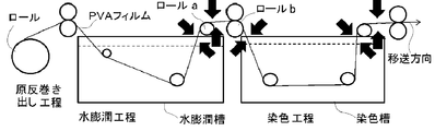
- FIG. 1 is a diagram schematically showing a location where a liquid is sprayed in 1) an original unwinding step, 2) a water swelling step, and 3) a dyeing step.
- FIG. 2 is a diagram schematically showing the distance A between the liquid level of the water swelling tank and the roll a and the distance B between the roll a and the roll b between 2) the water swelling process and 3) the dyeing process.
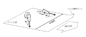
- FIG. 3A is a diagram showing a spraying mode when a liquid is sprayed on the surface of a polyvinyl alcohol film (PVA film).
- FIG. 3B is a diagram showing a spraying mode when a liquid is sprayed on the back surface of a polyvinyl alcohol film (PVA film).
- FIG. 4 is a diagram showing an angle ⁇ 1 formed by the spraying direction and the surface of the film when a liquid is sprayed on the front or back surface of the polyvinyl alcohol film.
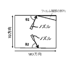
- FIG. 5 is a diagram illustrating an angle ⁇ 2 formed by a direction when the spraying direction is perpendicularly projected onto the surface of the polyvinyl alcohol film and a transfer direction of the polyvinyl alcohol film when a liquid is sprayed on the front or back surface of the polyvinyl alcohol film. It is.
- FIG. 5 is a diagram showing an angle ⁇ 1 formed by the spraying direction and the surface of the film when a liquid is sprayed on the front or back surface of the polyvinyl alcohol film.
- FIG. 6 shows an angle ⁇ 1 between the spraying direction and the surface of the film when the liquid is sprayed on the front surface or the back surface of the polyvinyl alcohol film, and the direction when the spraying direction is perpendicularly projected onto the surface of the polyvinyl alcohol film. It is a figure which shows angle (theta) 2 which makes with the transfer direction of an alcoholic film.
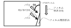
- FIG. 7 is a diagram showing an example of a spraying mode when a liquid is sprayed on a polyvinyl alcohol film.
- a step of unwinding a polyvinyl alcohol film from a roll and transferring it horizontally 2) a water swelling step, 3) a dyeing step, 4) a stretching step, and 5) boric acid
- a polarizing film is manufactured through a crosslinking step.
- 1) The process which unwinds a polyvinyl alcohol-type film from a roll and transfers it to a horizontal direction is also called 1) original fabric unwinding process below.
- the polyvinyl alcohol film used in the above 1) raw roll unwinding step is a film obtained by forming a polyvinyl alcohol resin into a film and wound up on a roll.
- polyvinyl alcohol resin used for the polyvinyl alcohol film an unmodified polyvinyl alcohol resin, that is, a resin produced by saponifying polyvinyl acetate obtained by polymerizing vinyl acetate is usually used.
- the polyvinyl alcohol film used in the present invention is not necessarily limited thereto, and can be copolymerized with vinyl acetate and a small amount (for example, 10 mol% or less, preferably 5 mol% or less) of vinyl acetate.
- a polyvinyl alcohol-based resin obtained by saponifying a copolymer with a component can also be used.
- components copolymerizable with vinyl acetate include unsaturated carboxylic acids (including salts, esters, amides, nitriles, etc.), and olefins having 2 to 30 carbon atoms (eg, ethylene, propylene, n-butene). , Isobutene, etc.), vinyl ethers, unsaturated sulfonates and the like.
- the modified polyvinyl alcohol-type resin obtained by chemically modifying the hydroxyl group after saponification can also be used.
- a polyvinyl alcohol resin having a 1,2-diol structure in the side chain can be used as the polyvinyl alcohol resin.
- a polyvinyl alcohol resin having a 1,2-diol structure in the side chain includes, for example, (i) a method for saponifying a copolymer of vinyl acetate and 3,4-diacetoxy-1-butene, and (ii) acetic acid.
- the weight average molecular weight of the polyvinyl alcohol resin is preferably 100,000 to 300,000, particularly preferably 110,000 to 280,000, and more preferably 120,000 to 260,000 from the viewpoint of optical performance and stretchability.
- the average saponification degree of the polyvinyl alcohol-based resin is usually preferably 98 mol% or more, particularly preferably 99 mol% or more, more preferably 99.5 mol% or more, particularly preferably from the viewpoint of optical performance. It is 99.8 mol% or more.
- polyvinyl alcohol resin used in the present invention two or more kinds having different modified species, modified amount, weight average molecular weight, average saponification degree, etc. may be used in combination.
- the polyvinyl alcohol film used in the present invention prepares a polyvinyl alcohol resin aqueous solution using the above polyvinyl alcohol resin, and discharges and flows the aqueous solution to a cast mold such as a cast drum, a cast belt, and a cast resin film. It is manufactured by rolling and forming a film, winding it on a roll after drying.
- polyvinyl alcohol-based resin aqueous solutions include plastics commonly used such as glycerin, diglycerin, triglycerin, ethylene glycol, triethylene glycol, polyethylene glycol, and trimethylol propane as necessary. It is preferable from the viewpoint of film forming property to contain an agent and a nonionic, anionic, and / or cationic surfactant.
- the resin concentration of the aqueous polyvinyl alcohol resin solution is preferably 10 to 60% by weight, particularly preferably 15 to 55% by weight, and further preferably 20 to 50% by weight.
- the temperature of the aqueous polyvinyl alcohol resin solution when discharged into a cast mold is preferably 80 to 100 ° C., particularly preferably 85 to 98 ° C.
- the discharge rate of the aqueous polyvinyl alcohol resin solution discharged into the cast mold is preferably 0.1 to 5 m / min, particularly preferably 0.2 to 4 m / min, and more preferably 0.3 to 3 m. / Min.
- the surface temperature of a cast mold such as a cast drum is preferably 40 to 99 ° C, particularly preferably 60 to 95 ° C.
- the film formed in the cast mold is dried by conveying the film while the front surface and the back surface of the film are alternately brought into contact with the outer peripheral portions of a plurality of heat rolls. After drying with a hot roll, the film may be heat treated. The heat treatment is preferably performed at 60 to 150 ° C., particularly preferably 80 to 130 ° C. Before winding the film on a roll, both ends of the film may be cut off with slits.
- the thickness of the polyvinyl alcohol film is preferably 5 to 60 ⁇ m from the viewpoint of thinning the polarizing film, particularly preferably 5 to 30 ⁇ m from the viewpoint of further thinning, from the viewpoint of avoiding breakage. More preferably, it is 10 to 30 ⁇ m.
- the width of the polyvinyl alcohol film is preferably 3 m or more, more preferably 4 m or more from the viewpoint of increasing the area, and further preferably 4 to 6 m from the viewpoint of avoiding breakage.
- the length of the polyvinyl alcohol film is preferably 4 km or more, particularly preferably 4.5 km or more, more preferably 5 km or more from the viewpoint of increasing the area.
- the upper limit of the length of the film is preferably 50 km or less, particularly preferably 40 km or less, and further preferably 30 km or less from the viewpoint of avoiding breakage.
- the timing of spraying the liquid is 2) after the water swelling process and / or 3) the dyeing process.
- the water swelling step particularly preferably 2) after the water swelling step, more preferably 2) within the range of 10 seconds after the water swelling step.
- the surface of the film to be sprayed is not particularly limited, and can be sprayed on the front surface, the back surface, and both surfaces.
- a polyvinyl alcohol film as a raw material is obtained by discharging and flowing an aqueous solution of a polyvinyl alcohol resin into a cast mold such as a cast belt and continuously drying the film. In such drying, the states on both sides are often not exactly the same, and the moisture on one side is often low or the degree of crystallinity is high.
- the surface with little moisture absorbs water and tends to stretch, the film tends to curl on the opposite surface side in the 2) water swelling process and 3) dyeing process in the production of the polarizing film. In such a case, in the present invention, it is effective to spray the liquid on both end portions on the opposite surface side in the curl direction.
- liquids to be sprayed examples include liquids such as water (including warm water), methanol, ethanol, isopropyl alcohol, acid / alkaline water, dyeing solution, glycerin aqueous solution, and various chemical aqueous solutions.
- water and a liquid such as a dyeing liquid are preferable because they do not adversely affect the performance of the polarizing film, and water is particularly preferable because of the simplicity of equipment.
- the water temperature is preferably 10 to 50 ° C., particularly preferably 20 to 40 ° C.
- mist-state liquid may be used as the sprayed liquid, and mist-state water is preferable from the viewpoint of not adversely affecting the performance of the polarizing film and the convenience of equipment.
- the liquid in the mist state is also simply referred to as “mist”.
- the mist is generally an artificial mist of a liquid and means a fine droplet.
- the particle size of the mist is usually from submicron to several hundred microns.
- the particle diameter of the mist used in the present invention is preferably 1 to 500 ⁇ m, particularly preferably 2 to 100 ⁇ m, and more preferably 3 to 50 ⁇ m. If the particle size of the mist is too large, spraying unevenness tends to occur, and if it is too small, it is difficult to control the spraying pressure, and it tends to float and adversely affect the environment.
- Mist can be sprayed using a commercially available mist spraying device.
- a mist spraying device include a one-fluid system that sprays liquid compressed by a pump from a nozzle, and a two-fluid system that sprays mist formed by colliding compressed liquid and compressed air.
- the one-fluid type is preferable because of the simplicity of equipment.
- the mist flow rate at the time of spraying is preferably 0.01 to 1 L / min, particularly preferably 0.1 to 0.5 L / min in terms of the spraying effect.
- examples of the shape of the mist ejected from the nozzle include a dot shape, a linear shape, a circular shape, and an oval shape.
- the ejection angle is not particularly limited, but is preferably 1 to 90 ° from the viewpoint of spraying effect.
- the nozzle made from a plastic excellent in corrosion resistance is preferable.
- the present invention will be described as an example of a preferred embodiment of the present invention, taking as an example the case where 2) the liquid is sprayed after the water swelling step.
- the water swelling step is preferably 10 to 45 ° C., particularly preferably 20 to 35 ° C., preferably 0.1 to 10 minutes, particularly preferably in terms of controlling the degree of swelling of the polyvinyl alcohol film. Is performed by immersing in water for 0.5 to 5 minutes.
- the water may contain a small amount of an iodide compound, an additive such as a surfactant, alcohol and the like.
- a polyvinyl alcohol film wound on a roll is unwound from the roll and transferred in the horizontal direction.
- the water swelling of the polyvinyl alcohol film is performed by the water swelling step. Thereafter, the polyvinyl alcohol film pulled up from the water swelling tank is transferred to a dyeing tank through a roll, and 3) the polyvinyl alcohol film is dyed in a dyeing step.
- the liquid is preferably sprayed on both ends of the film between 2) the water swelling process and 3) the dyeing process. Breaks and wrinkles are most likely to occur between these processes, and once the films are stuck together with the breaks or wrinkles, they are not easily peeled off.
- the processes 2) and 3) are the first processes for manufacturing the polarizing film, so the influence on the subsequent processes is significant.
- the specific position of spraying is, for example, 2) Immediately after coming out of the water swelling tank in the water swelling step and immediately after the first roll a.
- the position and direction of spraying are schematically shown by arrows in FIG.
- the distance A until the film exits the water swelling tank in 2) the water swelling step and comes into contact with the first roll a is 1 m or less. This is a case where the distance B from the roll a to the roll b just before the dyeing tank is 1 m or less. If the distance A is too long, there is a tendency for folds and wrinkles to increase.
- the distance A from the water swelling tank to the roll a represents the shortest distance from the liquid surface of the water swelling tank to the roll a, and the distance B from the first roll a to the roll b just before the dyeing tank is the same as that of the roll a. This represents the shortest distance between the roll b.
- the tension between the rolls in the series of steps is preferably 1 to 100 N / m. If the tension between the rolls is too large, it tends to break, and conversely if it is too small, it tends to increase creases and wrinkles. Furthermore, the transfer speed of the film from 2) the water swelling process to 3) the dyeing process is preferably 1 m / min or more, particularly preferably 1.5 m / min or more, more preferably 2 m from the viewpoint of productivity. / Min or more.
- liquid When spraying with a liquid, it is preferable to discharge the liquid onto one or both sides of both ends in the width direction of the film using a nozzle.
- liquid may be discharged onto the surface of the film, as shown in FIG. 3B, liquid may be discharged onto the back surface of the film, or liquid is discharged onto both surfaces of the film. May be.
- Such nozzles are not particularly limited, and known nozzles such as point discharge nozzles, line discharge nozzles, and surface discharge nozzles can be used, but point discharge is preferable from the viewpoint of controlling the spray position.
- a plurality of the same types of nozzles may be installed, or a plurality of types of nozzles may be combined.
- the position of the nozzle is preferably from the point of avoiding the breakage of the film until the film comes out of the water swelling tank in the water swelling step and comes into contact with the transport roll a.
- the distance from the outlet of the water swelling tank to the nozzle is within 1 m from the viewpoint of avoiding wrinkles of the film, and more preferably, within 0.5 m from the transport roll a to the nozzle from the viewpoint of film flatness. Is the distance.
- the distance from the outlet of the water swelling tank to the nozzle and the distance from the transport roll a to the nozzle each represent the shortest distance.
- the distance between the nozzle and the film surface is preferably 1 to 100 mm in terms of avoiding film breakage, and particularly preferably 2 to 50 mm in terms of avoiding film wrinkles. is there.
- the distance between the nozzle and the film surface represents the shortest distance, and specifically represents the distance between the nozzle and the film surface in a direction perpendicular to the film surface.
- the spraying flow velocity and the spraying angle are important in terms of curling prevention effects.
- the spraying flow rate is preferably 0.01 to 5 m / sec, particularly preferably 0.02 to 3 m / sec, and more preferably 0.03 to 2 m / sec. If the flow rate is too slow, the effect of preventing curling tends to decrease, and if the flow rate is too fast, the film tends to swell.
- the liquid spray direction is the film width direction (TD direction) or the film transport direction (MD Direction). Therefore, preferably, the angle of the liquid spray includes not only the angle ⁇ 1 formed by the liquid spray direction and the film surface, but also the direction when the liquid spray direction is vertically projected on the film surface and the film transport direction.
- the angle ⁇ 2 formed with the (MD direction) is included (see FIGS. 4 to 6). In FIG.
- the film transport direction is the x-axis
- the film width direction is the y-axis
- the direction perpendicular to the film surface is the z-axis
- the film surface is the xy surface
- the surface is perpendicular to the film surface.
- the plane parallel to the width direction is the yz plane
- the plane perpendicular to the film plane and parallel to the film transfer direction is the xz plane.
- the angle ⁇ 1 formed by the liquid spray direction and the film surface is preferably 5 to 80 °, particularly preferably 10 to 70 °, and further preferably 20 to 60 °. If the spray angle ⁇ 1 is too low, the effect of preventing curling tends to decrease, and if it is too high, the film tends to be swelled.
- the angle ⁇ 2 formed by the direction when the liquid spray direction is vertically projected on the film surface and the film transport direction (MD direction) is preferably 5 to 175 °, particularly preferably 20 to 90 °. More preferably, it is 30 to 60 °. If the spray angle ⁇ 2 is too low, the effect of preventing curling tends to decrease, and if it is too high, wrinkles tend to occur on the film.
- the flow velocity and the spray angle of the spraying may be the same for all nozzles or may be different for each nozzle.
- the spraying flow rate is gradually set lower from the upstream side to the downstream side in the film transfer direction (MD direction), or the spraying angle ⁇ 1 is gradually lowered. A method is mentioned.
- the polyvinyl alcohol film is transferred to the following 3) dyeing step and 4) stretching step in a state where there is no break or wrinkle.
- the polarizing film of the present invention is 1) after the unwinding step, 2) the water swelling step, 3) the dyeing step, 4) the stretching step, 5) the boric acid crosslinking step, and if necessary, the washing step and the drying step. It is manufactured through processes such as Such manufacturing steps are not necessarily performed in the order of 2) to 5), and a plurality of steps may be appropriately combined.
- 2) the stretching process may be performed simultaneously with 2) the water swelling process, 2) after the water swelling process, 3) the stretching process may be performed with the dyeing process, and 2) the water swelling process.
- 3) After the dyeing step, 5) The boric acid crosslinking step and 4) the stretching step may be performed, 2) the water swelling step, 3) the dyeing step, and 5) the boric acid crosslinking step.
- a stretching process may be performed.
- the dyeing step is performed by bringing the film into contact with a liquid containing iodine or a dichroic dye.
- a liquid containing iodine or a dichroic dye usually, an iodine-potassium iodide aqueous solution is used.
- the iodine concentration is suitably 0.1-2 g / L, and the potassium iodide concentration is 1-100 g / L.
- the dyeing time is practically about 30 to 500 seconds.
- the temperature of the treatment bath is preferably 5 to 50 ° C.
- the aqueous solution may contain a small amount of an organic solvent compatible with water in addition to the aqueous solvent.
- any means such as dipping, coating, spraying and the like can be applied.
- the stretching step is a step of stretching 3 to 10 times in a uniaxial direction, and it is particularly preferable to stretch 3.5 to 6 times.
- the film may be slightly stretched (stretching to prevent shrinkage in the width direction or more) in a direction perpendicular to the stretching direction.
- the temperature during stretching is preferably selected from a temperature range of 30 to 170 ° C.
- the draw ratio may be finally set within the above range, and the drawing operation may be performed not only in one stage but also in any stage of the manufacturing process.
- the boric acid crosslinking step is performed using a boron compound such as boric acid or borax.
- the boron compound is used in the form of an aqueous solution or a water-organic solvent mixed solution at a concentration of about 10 to 100 g / L, and it is preferable to allow a small amount of potassium iodide to coexist in the solution from the viewpoint of stabilizing the polarization performance.
- the treatment temperature is preferably about 30 to 70 ° C., and the treatment time is preferably about 0.1 to 20 minutes.
- the film may be washed.
- the precipitate generated on the surface of the film can be removed by the washing treatment.
- the cleaning treatment is performed, for example, by immersing a polyvinyl alcohol film in an aqueous iodide solution such as water or potassium iodide.
- an aqueous potassium iodide solution the concentration of potassium iodide may be about 1 to 80 g / L.
- the temperature during the washing treatment is usually 5 to 50 ° C., preferably 10 to 45 ° C.
- the treatment time is usually 1 to 300 seconds, preferably 10 to 240 seconds.
- the drying step may be performed in the atmosphere at 40 to 80 ° C. for 1 to 10 minutes.
- the polarization degree of the polarizing film thus obtained is preferably 99.8% or more, more preferably 99.9% or more. If the degree of polarization is too low, there is a tendency that the contrast in the liquid crystal display cannot be secured.
- the degree of polarization is generally the light transmittance (H 11 ) measured at the wavelength ⁇ in the state where two polarizing films are overlapped so that their orientation directions are the same direction, and the two polarizing films. It is calculated according to the following equation from the light transmittance (H 1 ) measured at the wavelength ⁇ in a state where the films are superposed so that the orientation directions are orthogonal to each other. [(H 11 ⁇ H 1 ) / (H 11 + H 1 )] 1/2
- the single transmittance of the polarizing film of the present invention is preferably 42% or more. If the single transmittance is too low, it tends to be impossible to achieve high brightness of the liquid crystal display.
- the single transmittance is a value obtained by measuring the light transmittance of a single polarizing film using a spectrophotometer.
- the width of the polarizing film of the present invention is preferably 1 m or more, preferably 1.3 m or more from the viewpoint of increasing the area, and particularly preferably 1.5 m or more from the viewpoint of further increasing the area. From the viewpoint of avoiding breakage, it is more preferably 1.5 to 2.5 m.
- the thickness of the polarizing film of the present invention is preferably 15 ⁇ m or less, particularly preferably 10 ⁇ m or less from the viewpoint of further thinning, more preferably 2 to 9 ⁇ m, particularly preferably from the viewpoint of avoiding breakage. Is 3 to 8 ⁇ m.
- the polarizing film of the present invention Since the polarizing film of the present invention thus obtained has little polarization unevenness, it is suitable for producing a high-performance polarizing plate.
- a method for producing a polarizing plate from the polarizing film of the present invention will be described.
- the polarizing film of the present invention is bonded to one side or both sides of an optically isotropic resin film as a protective film via an adhesive to form a polarizing plate.
- protective films include films of cellulose triacetate, cellulose diacetate, polycarbonate, polymethyl methacrylate, cycloolefin polymer, cycloolefin copolymer, polystyrene, polyethersulfone, polyarylene ester, poly-4-methylpentene, polyphenylene oxide, and the like. Or a sheet
- the bonding method is performed by a known method. For example, after a liquid adhesive composition is uniformly applied to a polarizing film, a protective film, or both, the two are bonded and pressure-bonded, and heating or active energy is applied. This is done by irradiating a line.
- a curable resin such as urethane resin, acrylic resin, urea resin or the like is applied to one side or both sides of the protective film and cured to obtain a polarizing plate.
- the polarizing film and polarizing plate obtained by the present invention are excellent in polarization performance, such as portable information terminals, personal computers, televisions, projectors, signage, electronic desk calculators, electronic watches, word processors, electronic paper, game machines, videos, cameras. , Photo albums, thermometers, audio, liquid crystal display devices such as automobile and machinery instruments, sunglasses, anti-glare glasses, stereoscopic glasses, wearable displays, reflection for display elements (CRT, LCD, organic EL, electronic paper, etc.) It is preferably used for a prevention layer, an optical communication device, a medical device, a building material, a toy and the like.
- polarization degree (%) was measured as follows.
- the polarization degree of the obtained polarizing film at the central part and both ends (each 10 cm from the end) in the width direction was measured using RETS-1100A manufactured by Otsuka Electronics Co., Ltd.
- Example 1 Manufacture of polyvinyl alcohol film
- Polyvinyl alcohol resin with a weight average molecular weight of 142,000, saponification degree of 99.8 mol%, 1000 kg of water, 2500 kg of water and 100 kg of glycerin as a plasticizer are added, and the temperature is raised to 140 ° C. with stirring to adjust the resin concentration to 25% by weight.
- the temperature is raised to 140 ° C. with stirring to adjust the resin concentration to 25% by weight.
- the polyvinyl alcohol-based resin aqueous solution is supplied to a twin-screw extruder having a vent and defoamed, and then the aqueous solution temperature is set to 95 ° C., and a cast drum having a surface temperature of 90 ° C. from the T-type slit die discharge port, The film was cast by casting at a discharge speed of 0.6 m / min. Next, the obtained film was dried with a plurality of hot rolls, subjected to heat treatment at 120 ° C. for 3 minutes using a floating dryer, and cut into a 4 m width with a slit.
- Nozzle Adjust hose made by MISUMI Nozzle position: 1 m from the outlet of the water swelling tank Nozzle position (height): 5mm from the top of the film Spraying flow velocity: 0.1 m / sec Spraying angle ⁇ 1: 30 ° Spray angle ⁇ 2: 45 °
- the obtained film was stretched in the transfer direction while being immersed and dyed in an aqueous solution composed of 0.9 g / L of iodine and 30 g / L of potassium iodide (0.5 minutes at 28 ° C., 1.6 times stretching ratio). ) [3) Dyeing step]. Next, it was immersed in an aqueous solution having a composition of boric acid 25 g / L and potassium iodide 30 g / L, and uniaxially stretched in the transport direction while crosslinking with boric acid (55 ° C. for 1 minute, stretch ratio 2.0 times) [5] Boric acid crosslinking step].
- the film was washed with an aqueous potassium iodide solution and dried to obtain a polarizing film having a total draw ratio of 5.4 times (width 1.8 m, thickness 7 ⁇ m).
- the obtained polarizing film was not broken or wrinkled, and no breakage occurred over a length of 12 km.
- Table 1 shows the polarization characteristics of the obtained polarizing film.
- a triacetyl cellulose film (TAC film) with a thickness of 40 ⁇ m was bonded to both surfaces of the obtained polarizing film using a polyvinyl alcohol-based aqueous solution as an adhesive, and dried at 50 ° C. to obtain a polarizing plate. Polarization unevenness was not observed in the obtained polarizing plate.
- Example 2 a polarizing film was obtained in the same manner as in Example 1 except that the spraying conditions were as shown in Table 1. The obtained polarizing film was not broken or wrinkled, and no breakage occurred over a length of 12 km. About the obtained polarizing film, evaluation similar to Example 1 was performed. The evaluation results are shown in Table 1. Further, a polarizing plate was obtained in the same manner as in Example 1. Polarization unevenness was not observed in the obtained polarizing plate.
- Example 5 a polarizing film was obtained in the same manner as Example 1 except that water was in a mist state.
- the mist spraying conditions are as follows. Nozzle: Hit jet nozzle manufactured by Spraying Systems, Inc. Nozzle position: 1 m from the outlet of the water swelling tank Nozzle position (height): 5mm from the top of the film Spraying flow velocity: 0.1 m / sec Spraying angle ⁇ 1: 30 ° Spray angle ⁇ 2: 45 ° Mist particle size: 20 ⁇ m Mist flow rate: 0.2 L / min Evaluation similar to Example 1 was performed about the obtained polarizing film. The evaluation results are shown in Table 1. Further, a polarizing plate was obtained in the same manner as in Example 1. Polarization unevenness was not observed in the obtained polarizing plate.
- Example 5 a polarizing film was obtained in the same manner as Example 5 except that the spraying conditions were as shown in Table 1. The obtained polarizing film was not broken or wrinkled, and no breakage occurred over a length of 12 km. About the obtained polarizing film, evaluation similar to Example 1 was performed. The evaluation results are shown in Table 1. Further, a polarizing plate was obtained in the same manner as in Example 1. Polarization unevenness was not observed in the obtained polarizing plate.
- Example 1 the production of the polarizing film was started in the same manner as in Example 1 except that the spraying was not performed. However, 2) After the water swelling step, folds and wrinkles were observed at both ends of the film, and when a polarizing film having a length of 1 km was produced, breakage occurred in the dyeing tank. Table 1 shows the polarization characteristics of the obtained part. In addition, since the fracture occurred, the polarizing plate could not be manufactured.
- a long polarizing film can be obtained without folds or wrinkles.
- the degree of polarization is high not only in the central part of the polarizing film but also at both ends in the width direction, a polarizing film having a uniform degree of polarization from the central part to the end part of the polarizing film can be obtained.
- the polarizing film of the present invention is a portable information terminal, personal computer, TV, projector, signage, electronic desk calculator, electronic clock, word processor, electronic paper, game machine, video, camera, photo album, thermometer, audio, automobile and machine.
- Liquid crystal display devices such as various instruments, sunglasses, anti-glare glasses, stereoscopic glasses, wearable displays, antireflection layers for display elements (CRT, LCD, organic EL, electronic paper, etc.), optical communication equipment, medical equipment, building materials Used for toys.
- PVA film polyvinyl alcohol-based film ⁇ 1 (°): angle formed by spraying direction and film surface ⁇ 2 (°): direction when the spraying direction is perpendicularly projected onto the surface of the polyvinyl alcohol-based film and transfer of the polyvinyl alcohol-based film Angle formed by direction Distance A: Distance between the liquid level of the water swelling tank and roll a Distance B: Distance between roll a and roll b
Landscapes
- Physics & Mathematics (AREA)
- Engineering & Computer Science (AREA)
- Nonlinear Science (AREA)
- Optics & Photonics (AREA)
- General Physics & Mathematics (AREA)
- Mechanical Engineering (AREA)
- Chemical & Material Sciences (AREA)
- Crystallography & Structural Chemistry (AREA)
- Mathematical Physics (AREA)
- Dispersion Chemistry (AREA)
- Manufacturing & Machinery (AREA)
- Ophthalmology & Optometry (AREA)
- Health & Medical Sciences (AREA)
- Polarising Elements (AREA)
- Shaping By String And By Release Of Stress In Plastics And The Like (AREA)
- Liquid Crystal (AREA)
Abstract
Description
かかる折れや皺を低減するために、乾燥処理でフィルムの幅方向に一定の張力をかける手法が提案されている(例えば特許文献1参照。)。また、水中走行中のフィルムの幅方向両端部にノズルから水を噴射する手法が提案されている(例えば特許文献2参照。)。
また、上記特許文献2の開示技術では、水中での折れや皺を回避できるものの、空中で発生する折れや皺を防ぐことができない。
そこで、本発明は、偏光膜の全製造工程において、折れや皺の問題を解決し、生産性良く偏光ムラの少ない偏光膜を製造することを目的としたものである。
〔偏光膜の製造方法〕
1)ポリビニルアルコール系フィルムをロールから巻き出して水平方向に移送する工程、2)水膨潤工程、3)染色工程、4)延伸工程、及び5)ホウ酸架橋工程を有する偏光膜の製造方法であって、
前記2)~4)のいずれかの工程の前及び/又は後において、前記フィルムの幅方向両端部に液体を吹き付けて前記フィルムのカールを防止することを特徴とする偏光膜の製造方法。
本発明の偏光膜の製造方法により製造される偏光膜。
本発明の偏光膜の少なくとも片面に保護フィルムが設けられてなることを特徴とする偏光板。
本発明においては、フィルムの幅方向を「TD方向」と称し、フィルムの移送方向を「MD方向」と称する。
なお、以下では、ポリビニルアルコール系フィルムを単に「フィルム」ともいう。
上記1)原反巻き出し工程に用いられるポリビニルアルコール系フィルムは、ポリビニルアルコール系樹脂をフィルム状に製膜し、ロールに巻き取られたものである。
ポリビニルアルコール系樹脂の平均ケン化度は、光学性能の点で、通常98モル%以上であることが好ましく、特に好ましくは99モル%以上、更に好ましくは99.5モル%以上、殊に好ましくは99.8モル%以上である。
キャスト型で製膜されたフィルムの乾燥は、フィルムの表面と裏面とを複数本の熱ロールの外周部に交互に接触させながら搬送させることにより行なわれる。熱ロールによる乾燥後、フィルムに熱処理を行ってもよい。熱処理については、60~150℃で行われることが好ましく、特には80~130℃が好ましい。
フィルムをロールに巻き取る前に、フィルムの両端部をスリットで切り落としてもよい。
また、ポリビニルアルコール系フィルムの幅は、3m以上であることが好ましく、大面積化の点から特に好ましくは4m以上、破断回避の点から更に好ましくは4~6mである。
また、ポリビニルアルコール系フィルムの長さは、4km以上であることが好ましく、大面積化の点から特に好ましくは4.5km以上、更に好ましくは5km以上である。
なお、フィルムの長さの上限は、破断回避の点から、好ましくは50km以下、特に好ましくは40km以下、更に好ましくは30km以下である。
4)延伸工程の後の5)ホウ酸架橋工程後や、その後の6)乾燥工程後に、液体の吹き付けを行うことも可能であるが、かかる工程ではフィルムが架橋や乾燥により高硬度になるので折れや皺は発生し難く、吹き付けによる効果は顕著では無い。
ここで、ミストとは、一般的に、液体を人工的に霧状にしたものであり、微小な液滴を意味する。ミストの粒径は、通常、サブミクロン~数百ミクロンである。本発明で使用されるミストの粒径は、好ましくは1~500μmであり、特に好ましくは2~100μm、更に好ましくは3~50μmである。ミストの粒径が大きすぎると、吹き付けムラが発生しやすい傾向にあり、小さすぎると吹き付け圧の制御が困難となり、また浮遊して環境に悪影響を及ぼす傾向にある。
例えば、図1に示すように、ロールに巻かれたポリビニルアルコール系フィルムをロールから巻き出して水平方向に移送する1)原反巻き出し工程を経て、水膨潤槽へ投入されたポリビニルアルコール系フィルムは、2)水膨潤工程により、ポリビニルアルコール系フィルムの水膨潤が行なわれる。その後、水膨潤槽から引き上げられたポリビニルアルコール系フィルムは、ロールを経て染色槽へと移送され、3)染色工程にてポリビニルアルコール系フィルムの染色が行なわれる。
また、一連の工程におけるロール間の張力は、1~100N/mであることが好ましい。ロール間の張力が大きすぎると、破断しやすい傾向があり、逆に小さすぎると、折れや皺が増加する傾向がある。
更に、2)水膨潤工程から3)染色工程に至るフィルムの移送速度は、生産性の点から、1m/分以上であることが好ましく、特に好ましくは1.5m/分以上、更に好ましくは2m/分以上である。
また、ノズルとフィルム面との間の距離は、フィルムの折れ回避の点で、1~100mmの距離であることが好ましく、特に好ましくは、フィルムの皺回避の点で、2~50mmの距離である。なお、ノズルとフィルム面との間の距離は最短距離を表し、具体的には、フィルム面に垂直な方向におけるノズルとフィルム面との間の距離を表す。
吹き付けの流速は、0.01~5m/秒であることが好ましく、特に好ましくは0.02~3m/秒、更に好ましくは0.03~2m/秒である。流速が遅すぎると、カール防止の効果が低下する傾向があり、流速が速すぎると、フィルムにうねりが生じやすい傾向がある。
なお、図6においては、フィルムの移送方向をx軸、フィルムの幅方向をy軸、フィルム面に垂直な方向をz軸とし、フィルム面をxy面、フィルム面に垂直な面であってフィルムの幅方向に平行な面をyz面、フィルム面に垂直な面であってフィルムの移送方向に平行な面をxz面としている。
また、液体の吹き付け方向をフィルムの面に垂直投影したときの方向とフィルムの移送方向(MD方向)とのなす角度θ2は、5~175°であることが好ましく、特に好ましくは20~90°であり、更に好ましくは30~60°である。吹き付け角度θ2が低すぎると、カール防止の効果が低下する傾向があり、高すぎると、フィルムに皺が生じる傾向がある。
なお、図7に示すように、複数のノズルを用いる場合、かかる吹き付けの流速と吹き付け角度は、全てのノズルが同じであっても、ノズルごとに異なっていてもよい。ノズルごとに異なる手法としては、例えば、フィルムの移送方向(MD方向)の上流側から下流側へ向かって、吹き付け流速を徐々に低く設定したり、吹き付け角度θ1を徐々に低角度にするなどの手法が挙げられる。
乾燥工程は、大気中で40~80℃で1~10分間行えばよい。
なお、偏光度は、一般的に2枚の偏光膜を、その配向方向が同一方向になるように重ね合わせた状態で、波長λにおいて測定した光線透過率(H11)と、2枚の偏光膜を、配向方向が互いに直交する方向になる様に重ね合わせた状態で、波長λにおいて測定した光線透過率(H1)より、下式にしたがって算出される。
〔(H11-H1)/(H11+H1)〕1/2
単体透過率は、分光光度計を用いて偏光膜単体の光線透過率を測定して得られる値である。
以下、本発明の偏光膜から偏光板を製造する方法について説明する。
実施例及び比較例で得られた偏光膜について下記のとおりに偏光度(%)を測定した。
得られた偏光膜の幅方向の中央部と両端部(それぞれ端から10cmの箇所)の偏光度を、大塚電子(株)製:RETS-1100Aを用いて測定した。
(ポリビニルアルコール系フィルムの製造)
重量平均分子量142000、ケン化度99.8モル%のポリビニルアルコール系樹脂1000kg、水2500kg、可塑剤としてグリセリン100kgを入れ、撹拌しながら140℃まで昇温して、樹脂濃度25重量%に濃度調整を行い、均一に溶解したポリビニルアルコール系樹脂水溶液を得た。
次に、該ポリビニルアルコール系樹脂水溶液を、ベントを有する二軸押出機に供給して脱泡した後、水溶液温度を95℃にし、T型スリットダイ吐出口から表面温度90℃のキャストドラムに、吐出速度0.6m/分で流延して製膜した。
次いで、得られたフィルムを複数の熱ロールで乾燥し、フローティングドライヤーを用いて120℃で3分間の熱処理を行い、4m幅にスリットで切り落とした。最後に、外径17cm、内径16cm、長さ4.4mのアルミニウム製芯管に巻き取ることによって、含水率が2重量%の帯状のポリビニルアルコール系フィルム(幅4m、長さ5km、厚さ15μm)が芯管に巻き付けられたフィルムロールを得た。
得られたポリビニルアルコール系フィルムを、ロールから巻き出して水平方向に移送しながら〔1)原反巻き出し工程〕、水膨潤槽の温水に浸漬して膨潤させながら、移送方向へ延伸した(25℃で1分間、延伸倍率1.7倍)〔2)水膨潤工程〕。
水膨潤槽からフィルムを引き上げ、水平に配置された2つのロール間で(ロール間の距離1m、ロール間の張力20N/m)、移送速度2m/分で水平方向に搬送されるフィルムの両端部に、ノズルで上側から水(23℃)を吹き付けてカールを防止した。かかる水の吹き付け条件は以下のとおりである。
ノズル:ミスミ社製アジャストホース
ノズル位置:水膨潤槽出口から1m
ノズル位置(高さ):フィルム上面から5mm
吹き付け流速:0.1m/秒
吹き付け角度θ1:30°
吹き付け角度θ2:45°
次いで、ホウ酸25g/L、ヨウ化カリウム30g/Lの組成の水溶液に浸漬し、ホウ酸架橋しながら、移送方向へ一軸延伸した(55℃1分、延伸倍率2.0倍)〔5)ホウ酸架橋工程〕。
その後、ヨウ化カリウム水溶液で洗浄を行い、乾燥して総延伸倍率5.4倍の偏光膜を得た(幅1.8m、厚さ7μm)。得られた偏光膜に折れ又は皺は無く、長さ12kmにわたって破断は生じなかった。得られた偏光膜の偏光特性を表1に示す。
得られた偏光膜の両面に、厚さ40μmのトリアセチルセルロースフイルム(TACフィルム)を、ポリビニルアルコール系水溶液を接着剤として用いて貼合し、50℃で乾燥して偏光板とした。得られた偏光板に偏光ムラは観察されなかった。
実施例1において、吹き付け条件を表1に示される条件とする以外は実施例1と同様にして、偏光膜を得た。得られた偏光膜に折れや皺は無く、長さ12kmにわたって破断は生じなかった。得られた偏光膜について、実施例1と同様の評価を行った。評価結果を表1に示す。更に、実施例1と同様にして偏光板を得た。得られた偏光板に偏光ムラは観察されなかった。
実施例1において、水をミスト状態にする以外は実施例1と同様にして、偏光膜を得た。かかるミストの吹き付け条件は以下のとおりである。
ノズル:スプレーイング システムズ社製ヒットジェットノズル
ノズル位置:水膨潤槽出口から1m
ノズル位置(高さ):フィルム上面から5mm
吹き付け流速:0.1m/秒
吹き付け角度θ1:30°
吹き付け角度θ2:45°
ミスト粒径:20μm
ミスト流量:0.2L/分
得られた偏光膜について、実施例1と同様の評価を行った。評価結果を表1に示す。更に、実施例1と同様にして偏光板を得た。得られた偏光板に偏光ムラは観察されなかった。
実施例5において、吹き付け条件を表1に示される条件とする以外は実施例5と同様にして、偏光膜を得た。得られた偏光膜に折れや皺は無く、長さ12kmにわたって破断は生じなかった。得られた偏光膜について、実施例1と同様の評価を行った。評価結果を表1に示す。更に、実施例1と同様にして偏光板を得た。得られた偏光板に偏光ムラは観察されなかった。
実施例1において、吹き付けを行わない以外は実施例1と同様にして、偏光膜の製造を開始した。しかし、2)水膨潤工程以降、フィルムの両端部に折れや皺が観察され、長さ1kmの偏光膜を製造したところで、染色槽において破断が生じた。得られた部分の偏光特性を表1に示す。なお、破断が生じたため、偏光板の製造はできなかった。

θ1(°):吹き付け方向とフィルムの面とのなす角度
θ2(°):吹き付け方向をポリビニルアルコール系フィルムの面に垂直投影したときの方向とポリビニルアルコール系フィルムの移送方向とのなす角度
距離A:水膨潤槽の液面とロールaとの距離
距離B:ロールaとロールbとの間の距離
Claims (15)
- 1)ポリビニルアルコール系フィルムをロールから巻き出して水平方向に移送する工程、2)水膨潤工程、3)染色工程、4)延伸工程、及び5)ホウ酸架橋工程を有する偏光膜の製造方法であって、
前記2)~4)のいずれかの工程の前及び/又は後において、前記フィルムの幅方向両端部に液体を吹き付けて前記フィルムのカールを防止することを特徴とする偏光膜の製造方法。 - 前記液体の吹き付けが、2)水膨潤工程の後に行なわれることを特徴とする請求項1記載の偏光膜の製造方法。
- 前記液体の吹き付け方向と前記フィルムの面とのなす角度が5~80°であることを特徴とする請求項1又は2記載の偏光膜の製造方法。、
- 前記液体の吹き付け方向を前記フィルムの面に垂直投影したときの方向と、前記フィルムの移送方向とのなす角度が5~175°であることを特徴とする請求項1~3いずれか記載の偏光膜の製造方法。
- 前記液体の吹き付けが、流速0.01~5m/秒で行なわれることを特徴とする請求項1~4いずれか記載の偏光膜の製造方法。
- 前記液体が、水または染色液であることを特徴とする請求項1~5いずれか記載の偏光膜の製造方法。
- 前記液体が、ミスト状態の液体であることを特徴とする請求項1~6いずれか記載の偏光膜の製造方法。
- 前記ミスト状態の液体が、圧縮した液体をノズルから噴霧することで形成されることを特徴とする請求項7記載の偏光膜の製造方法。
- 前記ミスト状態の液体におけるミストの粒径が、1~500μmであることを特徴とする請求項7又は8記載の偏光膜の製造方法。
- 前記ミスト状態の液体の流量が、0.01~1L/分であることを特徴とする請求項7~9いずれか記載の偏光膜の製造方法。
- 前記2)水膨潤工程から前記3)染色工程に至る前記フィルムの移送速度が、1m/分以上であることを特徴とする請求項1~10いずれか記載の偏光膜の製造方法。
- 偏光膜の厚さが15μm以下であることを特徴とする請求項1~11いずれか記載の偏光膜の製造方法。
- 偏光膜の幅が1m以上であることを特徴とする請求項1~12いずれか記載の偏光膜の製造方法。
- 請求項1~13いずれか記載の偏光膜の製造方法により製造される偏光膜。
- 請求項14記載の偏光膜の少なくとも片面に保護フィルムが設けられてなることを特徴とする偏光板。
Priority Applications (3)
| Application Number | Priority Date | Filing Date | Title |
|---|---|---|---|
| CN201680041968.6A CN107850718B (zh) | 2015-09-30 | 2016-06-17 | 偏光膜的制造方法、偏光膜及偏光板 |
| JP2016541455A JP6733542B2 (ja) | 2015-09-30 | 2016-06-17 | 偏光膜の製造方法 |
| KR1020187012159A KR102400122B1 (ko) | 2015-09-30 | 2016-06-17 | 편광막의 제조 방법, 편광막, 및 편광판 |
Applications Claiming Priority (2)
| Application Number | Priority Date | Filing Date | Title |
|---|---|---|---|
| JP2015-193775 | 2015-09-30 | ||
| JP2015193775 | 2015-09-30 |
Publications (1)
| Publication Number | Publication Date |
|---|---|
| WO2017056579A1 true WO2017056579A1 (ja) | 2017-04-06 |
Family
ID=58423375
Family Applications (1)
| Application Number | Title | Priority Date | Filing Date |
|---|---|---|---|
| PCT/JP2016/068185 Ceased WO2017056579A1 (ja) | 2015-09-30 | 2016-06-17 | 偏光膜の製造方法、偏光膜及び偏光板 |
Country Status (5)
| Country | Link |
|---|---|
| JP (1) | JP6733542B2 (ja) |
| KR (1) | KR102400122B1 (ja) |
| CN (1) | CN107850718B (ja) |
| TW (1) | TWI693248B (ja) |
| WO (1) | WO2017056579A1 (ja) |
Families Citing this family (2)
| Publication number | Priority date | Publication date | Assignee | Title |
|---|---|---|---|---|
| JP7412081B2 (ja) * | 2017-12-27 | 2024-01-12 | 三菱ケミカル株式会社 | 偏光膜製造用ポリビニルアルコール系フィルム、及びそれを用いて得られる偏光膜、ならびにポリビニルアルコール系樹脂水溶液 |
| CN120228889B (zh) * | 2025-04-07 | 2026-04-21 | 苏州泓鑫翔机械有限公司 | 一种带梯度加热功能的pvc薄膜生产拉薄装置 |
Citations (4)
| Publication number | Priority date | Publication date | Assignee | Title |
|---|---|---|---|---|
| JPH07247378A (ja) * | 1994-03-09 | 1995-09-26 | Nippon Synthetic Chem Ind Co Ltd:The | ビニルアルコール系重合体フィルムの水中走行時の水流拡巾方法および装置 |
| JP2000147251A (ja) * | 1998-11-10 | 2000-05-26 | Nitto Denko Corp | 偏光フィルムの製造方法及び偏光板 |
| JP2001315140A (ja) * | 2000-05-09 | 2001-11-13 | Kuraray Co Ltd | ポリビニルアルコール系重合体フィルムとその製造法および偏光フィルム |
| JP2014146035A (ja) * | 2014-02-27 | 2014-08-14 | Nitto Denko Corp | 偏光子の製造方法、偏光子、偏光板、光学フィルムおよび画像表示装置 |
Family Cites Families (4)
| Publication number | Priority date | Publication date | Assignee | Title |
|---|---|---|---|---|
| JP4581690B2 (ja) | 2005-01-05 | 2010-11-17 | 住友化学株式会社 | 偏光フィルムの製造方法 |
| JP5382843B2 (ja) * | 2007-10-31 | 2014-01-08 | 住友化学株式会社 | 偏光板の製造方法 |
| JP6228359B2 (ja) * | 2011-12-06 | 2017-11-08 | 住友化学株式会社 | 偏光フィルムの製造方法 |
| JP6462199B2 (ja) * | 2012-12-04 | 2019-01-30 | 住友化学株式会社 | 偏光フィルム及び偏光板の製造方法 |
-
2016
- 2016-06-17 WO PCT/JP2016/068185 patent/WO2017056579A1/ja not_active Ceased
- 2016-06-17 KR KR1020187012159A patent/KR102400122B1/ko active Active
- 2016-06-17 CN CN201680041968.6A patent/CN107850718B/zh active Active
- 2016-06-17 JP JP2016541455A patent/JP6733542B2/ja active Active
- 2016-08-09 TW TW105125233A patent/TWI693248B/zh active
Patent Citations (4)
| Publication number | Priority date | Publication date | Assignee | Title |
|---|---|---|---|---|
| JPH07247378A (ja) * | 1994-03-09 | 1995-09-26 | Nippon Synthetic Chem Ind Co Ltd:The | ビニルアルコール系重合体フィルムの水中走行時の水流拡巾方法および装置 |
| JP2000147251A (ja) * | 1998-11-10 | 2000-05-26 | Nitto Denko Corp | 偏光フィルムの製造方法及び偏光板 |
| JP2001315140A (ja) * | 2000-05-09 | 2001-11-13 | Kuraray Co Ltd | ポリビニルアルコール系重合体フィルムとその製造法および偏光フィルム |
| JP2014146035A (ja) * | 2014-02-27 | 2014-08-14 | Nitto Denko Corp | 偏光子の製造方法、偏光子、偏光板、光学フィルムおよび画像表示装置 |
Also Published As
| Publication number | Publication date |
|---|---|
| CN107850718B (zh) | 2021-01-12 |
| CN107850718A (zh) | 2018-03-27 |
| KR20180063205A (ko) | 2018-06-11 |
| KR102400122B1 (ko) | 2022-05-19 |
| TW201726770A (zh) | 2017-08-01 |
| JPWO2017056579A1 (ja) | 2018-07-19 |
| TWI693248B (zh) | 2020-05-11 |
| JP6733542B2 (ja) | 2020-08-05 |
Similar Documents
| Publication | Publication Date | Title |
|---|---|---|
| JP6743502B2 (ja) | ポリビニルアルコール系フィルムの製造方法 | |
| WO2017195813A1 (ja) | ポリビニルアルコール系フィルム、およびその製造方法、ならびにそのポリビニルアルコール系フィルムを用いた偏光膜 | |
| WO2017073638A1 (ja) | ポリビニルアルコール系フィルム、およびそれを用いた偏光膜、偏光板、ならびにポリビニルアルコール系フィルムの製造方法 | |
| TWI771278B (zh) | 聚乙烯醇系膜及利用此聚乙烯醇系膜之偏光膜、偏光板與聚乙烯醇系膜之製造方法 | |
| JP6784142B2 (ja) | 偏光膜製造用ポリビニルアルコール系フィルムの製造方法 | |
| JP6262377B2 (ja) | ポリビニルアルコール系フィルムの製造方法 | |
| JPWO2017204271A1 (ja) | ポリビニルアルコール系フィルム、およびその製造方法、ならびにそのポリビニルアルコール系フィルムを用いた偏光膜 | |
| JP7335697B2 (ja) | ポリビニルアルコール系フィルム、偏光膜および偏光板、ならびにポリビニルアルコール系フィルムの製造方法 | |
| WO2017195812A1 (ja) | ポリビニルアルコール系フィルム、およびその製造方法、ならびにそのポリビニルアルコール系フィルムを用いた偏光膜 | |
| JPWO2016208652A1 (ja) | ポリビニルアルコール系フィルム、ポリビニルアルコール系フィルムの製造方法、及び偏光膜 | |
| KR102629982B1 (ko) | 편광막 제조용 폴리비닐 알코올계 필름 및 이를 사용한 편광막, 편광판, 및 편광막 제조용 폴리비닐 알코올계 필름의 제조 | |
| JP6878778B2 (ja) | ポリビニルアルコール系フィルムの製造方法 | |
| WO2018199140A1 (ja) | ポリビニルアルコール系フィルム、偏光膜および偏光板、ならびにポリビニルアルコール系フィルムの製造方法 | |
| CN107107404B (zh) | 聚乙烯醇系薄膜、聚乙烯醇系薄膜的制造方法、偏振膜及偏振片 | |
| JP6733542B2 (ja) | 偏光膜の製造方法 | |
| JP6733543B2 (ja) | 偏光膜の製造方法 | |
| JP6740857B2 (ja) | 偏光膜製造用ポリビニルアルコール系フィルムの製造方法 | |
| JP2016203623A (ja) | ポリビニルアルコール系フィルムの製造方法、ポリビニルアルコール系フィルム、及び偏光膜 | |
| JP2017223941A (ja) | 偏光膜用ポリビニルアルコール系フィルム、およびその製造方法、ならびに偏光膜 | |
| JP2016172851A (ja) | ポリビニルアルコール系フィルム、ポリビニルアルコール系フィルムの製造方法、偏光フィルム及び偏光板 | |
| JPWO2019131716A1 (ja) | 偏光膜製造用ポリビニルアルコール系フィルム、及びそれを用いて得られる偏光膜、ならびにポリビニルアルコール系樹脂水溶液 | |
| JP6784141B2 (ja) | 偏光膜製造用ポリビニルアルコール系フィルムの製造方法 | |
| CN121263720A (zh) | 聚乙烯醇薄膜和使用其的偏振膜、以及偏振板、聚乙烯醇薄膜的制造方法 | |
| KR102636662B1 (ko) | 폴리비닐 알코올계 필름 및 이를 사용한 편광막, 편광판 및 폴리비닐 알코올계 필름의 제조 방법 | |
| JP2022148527A (ja) | ポリビニルアルコール系偏光子、偏光板およびその製造方法 |
Legal Events
| Date | Code | Title | Description |
|---|---|---|---|
| ENP | Entry into the national phase |
Ref document number: 2016541455 Country of ref document: JP Kind code of ref document: A |
|
| 121 | Ep: the epo has been informed by wipo that ep was designated in this application |
Ref document number: 16850756 Country of ref document: EP Kind code of ref document: A1 |
|
| NENP | Non-entry into the national phase |
Ref country code: DE |
|
| ENP | Entry into the national phase |
Ref document number: 20187012159 Country of ref document: KR Kind code of ref document: A |
|
| 122 | Ep: pct application non-entry in european phase |
Ref document number: 16850756 Country of ref document: EP Kind code of ref document: A1 |