WO2017056540A1 - 基板処理方法および基板処理装置 - Google Patents
基板処理方法および基板処理装置 Download PDFInfo
- Publication number
- WO2017056540A1 WO2017056540A1 PCT/JP2016/062744 JP2016062744W WO2017056540A1 WO 2017056540 A1 WO2017056540 A1 WO 2017056540A1 JP 2016062744 W JP2016062744 W JP 2016062744W WO 2017056540 A1 WO2017056540 A1 WO 2017056540A1
- Authority
- WO
- WIPO (PCT)
- Prior art keywords
- substrate
- brush
- droplets
- nozzle
- cleaning step
- Prior art date
- Legal status (The legal status is an assumption and is not a legal conclusion. Google has not performed a legal analysis and makes no representation as to the accuracy of the status listed.)
- Ceased
Links
Images


Classifications
-
- H—ELECTRICITY
- H10—SEMICONDUCTOR DEVICES; ELECTRIC SOLID-STATE DEVICES NOT OTHERWISE PROVIDED FOR
- H10P—GENERIC PROCESSES OR APPARATUS FOR THE MANUFACTURE OR TREATMENT OF DEVICES COVERED BY CLASS H10
- H10P72/00—Handling or holding of wafers, substrates or devices during manufacture or treatment thereof
- H10P72/04—Apparatus for manufacture or treatment
- H10P72/0402—Apparatus for fluid treatment
- H10P72/0406—Apparatus for fluid treatment for cleaning followed by drying, rinsing, stripping, blasting or the like
- H10P72/0411—Apparatus for fluid treatment for cleaning followed by drying, rinsing, stripping, blasting or the like for wet cleaning or washing
- H10P72/0412—Apparatus for fluid treatment for cleaning followed by drying, rinsing, stripping, blasting or the like for wet cleaning or washing using mainly scrubbing means, e.g. brushes
-
- B—PERFORMING OPERATIONS; TRANSPORTING
- B08—CLEANING
- B08B—CLEANING IN GENERAL; PREVENTION OF FOULING IN GENERAL
- B08B1/00—Cleaning by methods involving the use of tools
- B08B1/20—Cleaning of moving articles, e.g. of moving webs or of objects on a conveyor
-
- B—PERFORMING OPERATIONS; TRANSPORTING
- B08—CLEANING
- B08B—CLEANING IN GENERAL; PREVENTION OF FOULING IN GENERAL
- B08B1/00—Cleaning by methods involving the use of tools
- B08B1/30—Cleaning by methods involving the use of tools by movement of cleaning members over a surface
- B08B1/32—Cleaning by methods involving the use of tools by movement of cleaning members over a surface using rotary cleaning members
- B08B1/36—Cleaning by methods involving the use of tools by movement of cleaning members over a surface using rotary cleaning members rotating about an axis orthogonal to the surface
-
- B—PERFORMING OPERATIONS; TRANSPORTING
- B08—CLEANING
- B08B—CLEANING IN GENERAL; PREVENTION OF FOULING IN GENERAL
- B08B3/00—Cleaning by methods involving the use or presence of liquid or steam
- B08B3/02—Cleaning by the force of jets or sprays
- B08B3/022—Cleaning travelling work
-
- H—ELECTRICITY
- H10—SEMICONDUCTOR DEVICES; ELECTRIC SOLID-STATE DEVICES NOT OTHERWISE PROVIDED FOR
- H10P—GENERIC PROCESSES OR APPARATUS FOR THE MANUFACTURE OR TREATMENT OF DEVICES COVERED BY CLASS H10
- H10P52/00—Grinding, lapping or polishing of wafers, substrates or parts of devices
-
- H—ELECTRICITY
- H10—SEMICONDUCTOR DEVICES; ELECTRIC SOLID-STATE DEVICES NOT OTHERWISE PROVIDED FOR
- H10P—GENERIC PROCESSES OR APPARATUS FOR THE MANUFACTURE OR TREATMENT OF DEVICES COVERED BY CLASS H10
- H10P72/00—Handling or holding of wafers, substrates or devices during manufacture or treatment thereof
- H10P72/04—Apparatus for manufacture or treatment
- H10P72/0402—Apparatus for fluid treatment
- H10P72/0406—Apparatus for fluid treatment for cleaning followed by drying, rinsing, stripping, blasting or the like
- H10P72/0411—Apparatus for fluid treatment for cleaning followed by drying, rinsing, stripping, blasting or the like for wet cleaning or washing
- H10P72/0414—Apparatus for fluid treatment for cleaning followed by drying, rinsing, stripping, blasting or the like for wet cleaning or washing using mainly spraying means, e.g. nozzles
-
- B—PERFORMING OPERATIONS; TRANSPORTING
- B08—CLEANING
- B08B—CLEANING IN GENERAL; PREVENTION OF FOULING IN GENERAL
- B08B1/00—Cleaning by methods involving the use of tools
- B08B1/10—Cleaning by methods involving the use of tools characterised by the type of cleaning tool
- B08B1/12—Brushes
-
- H—ELECTRICITY
- H10—SEMICONDUCTOR DEVICES; ELECTRIC SOLID-STATE DEVICES NOT OTHERWISE PROVIDED FOR
- H10P—GENERIC PROCESSES OR APPARATUS FOR THE MANUFACTURE OR TREATMENT OF DEVICES COVERED BY CLASS H10
- H10P70/00—Cleaning of wafers, substrates or parts of devices
- H10P70/10—Cleaning before device manufacture, i.e. Begin-Of-Line process
- H10P70/15—Cleaning before device manufacture, i.e. Begin-Of-Line process by wet cleaning only
-
- H—ELECTRICITY
- H10—SEMICONDUCTOR DEVICES; ELECTRIC SOLID-STATE DEVICES NOT OTHERWISE PROVIDED FOR
- H10P—GENERIC PROCESSES OR APPARATUS FOR THE MANUFACTURE OR TREATMENT OF DEVICES COVERED BY CLASS H10
- H10P70/00—Cleaning of wafers, substrates or parts of devices
- H10P70/50—Cleaning of wafers, substrates or parts of devices characterised by the part to be cleaned
- H10P70/54—Cleaning of wafer edges
-
- H—ELECTRICITY
- H10—SEMICONDUCTOR DEVICES; ELECTRIC SOLID-STATE DEVICES NOT OTHERWISE PROVIDED FOR
- H10P—GENERIC PROCESSES OR APPARATUS FOR THE MANUFACTURE OR TREATMENT OF DEVICES COVERED BY CLASS H10
- H10P70/00—Cleaning of wafers, substrates or parts of devices
- H10P70/60—Cleaning only by mechanical processes
Definitions
- the present invention relates to a substrate processing method and a substrate processing apparatus for processing a substrate.
- substrates to be processed include semiconductor wafers, liquid crystal display substrates, plasma display substrates, FED (Field (Emission Display) substrates, optical disk substrates, magnetic disk substrates, magneto-optical disk substrates, and photomasks.
- substrate semiconductor wafers, liquid crystal display substrates, plasma display substrates, FED (Field (Emission Display) substrates, optical disk substrates, magnetic disk substrates, magneto-optical disk substrates, and photomasks.
- substrate ceramic substrate, solar cell substrate and the like.
- Patent Document 1 discloses a substrate processing apparatus for cleaning an outer peripheral portion of a substrate with a brush.
- This substrate processing apparatus includes a spin chuck that rotates around a vertical rotation axis passing through a central portion of the substrate while holding the substrate horizontally, and a brush that presses a drum-shaped brush against the outer peripheral portion of the substrate held by the spin chuck And a moving mechanism. The brush is pressed against the outer periphery of the lower surface of the rotating substrate and then pressed against the outer periphery of the upper surface of the rotating substrate.
- Patent Document 1 since the brush is pressed against the outer peripheral portion (so-called bevel portion) of the substrate, foreign substances adhering to the outer peripheral portion of the substrate can be physically removed. However, the configuration of Patent Document 1 cannot physically clean the upper surface of the substrate.
- the inventors physically hit the upper surface of the substrate as well as the outer peripheral portion of the substrate by causing a plurality of droplets to collide with the upper surface of the substrate while bringing the brush into contact with the outer peripheral portion of the rotating substrate.
- the cleaning time of the substrate can be shortened while increasing the cleanliness of the substrate.
- the present inventors have found that there is a possibility that the cleanliness cannot be sufficiently increased by simply simultaneously cleaning the outer peripheral portion and the upper surface of the substrate.
- one of the objects of the present invention is to increase the cleanliness of the substrate while suppressing an increase in the cleaning time of the substrate.
- the collision position of the plurality of droplets with respect to the upper surface of the substrate is determined in the substrate while causing the plurality of droplets to collide with the upper surface of the substrate. And including an outer peripheral side spray cleaning step of moving between an outer periphery of the substrate, to provide a substrate processing method.
- the brush comes into contact with the inclined portion on the lower surface of the rotating substrate. Thereby, the brush is rubbed around the entire circumference of the lower surface of the substrate. Foreign matters such as particles are peeled off from the substrate by a physical force from the brush.
- the plurality of droplets collide with a region in the upper surface of the substrate between the center of the substrate and the middle of the substrate in parallel with the cleaning of the inclined portion on the lower surface of the substrate. Foreign substances such as particles are peeled off from the substrate by a physical force due to the collision of droplets.
- the brush comes into contact with the upper surface inclined portion of the rotating substrate. Thereby, a brush is rubbed to the perimeter of the upper surface of a board
- the plurality of droplets collide with a region in the upper surface of the substrate between the middle of the substrate and the outer periphery of the substrate in parallel with the cleaning of the inclined portion on the upper surface of the substrate. In this way, the upper surface of the substrate is physically cleaned in parallel with the physical cleaning of the outer peripheral portion of the substrate, so that the cleanliness of the substrate can be increased while suppressing an increase in cleaning time.
- the area where the flying object easily falls that is, the area within the upper surface of the substrate between the middle of the substrate and the outer periphery of the substrate, is cleaned with a plurality of droplets when the brush is in contact with the inclined surface of the upper surface of the substrate. Is done. Therefore, the scattered matter adhering to the upper surface of the substrate can be removed immediately. In this way, not only the foreign matter adhering to the outer peripheral portion of the upper surface of the substrate but also the scattered matter scattered from the brush to the outer peripheral portion of the upper surface of the substrate can be removed with a plurality of droplets, thereby further increasing the cleanliness of the substrate. Can do.
- At least one of the following features may be added to the substrate processing method.
- Both the center side spray cleaning step and the outer periphery side spray cleaning step are steps in which the collision position of a plurality of droplets with respect to the upper surface of the substrate is moved only to the outer periphery side of the substrate.
- the center-side spray cleaning step is a step in which the step of moving the collision position of the plurality of droplets with respect to the upper surface of the substrate from the center of the substrate to the middle of the substrate is performed once or more.
- the outer peripheral side spray cleaning step is a step of performing the step of moving the collision position of the plurality of droplets with respect to the upper surface of the substrate from the middle of the substrate to the outer periphery of the substrate one or more times.
- the collision position of the plurality of droplets with respect to the upper surface of the substrate moves only to the outer peripheral side of the substrate, so that a force for moving the foreign matter on the substrate outward is generated. Therefore, the foreign matter on the substrate is urged to move outward along the upper surface of the substrate. Thereby, foreign substances can be efficiently removed from the substrate, and the cleanliness of the substrate can be further increased.
- the substrate processing method further includes an upper rinsing liquid supply step of discharging a rinsing liquid toward the center of the upper surface of the substrate in parallel with the center side spray cleaning step and the outer peripheral side spray cleaning step.
- the rinse liquid is discharged toward the center of the upper surface of the rotating substrate.
- the rinse liquid deposited on the upper surface of the substrate flows outward along the upper surface of the substrate.
- the foreign matter peeled off from the upper surface of the substrate by the collision of the liquid droplets is urged to move outward by the rinse liquid flowing outward. Therefore, foreign substances can be efficiently removed from the substrate, and the cleanliness of the substrate can be further increased.
- the collision position of the plurality of droplets with respect to the upper surface of the substrate is set between the middle of the substrate and the outer periphery of the substrate inside the region where the upper surface of the substrate and the brush are in contact with each other. It is the process of moving by.
- the collision position of the plurality of droplets with respect to the upper surface of the substrate moves inside the region where the upper surface of the substrate and the brush are in contact with each other. That is, scrub cleaning (cleaning with a brush) and spray cleaning (cleaning by collision of droplets) are performed in different regions of the substrate.
- scrub cleaning and spray cleaning are not performed on the same region of the substrate, the substrate cleaning time can be shortened.
- a substrate holding unit that rotates around a vertical rotation axis passing through the substrate while holding the substrate horizontally, a brush that is pressed against the substrate, and a brush that is a lower inclined portion of the substrate
- a brush moving mechanism that moves the brush to a plurality of positions including a lower contact position that contacts the upper surface and an upper contact position at which the brush contacts the upper surface inclined portion of the substrate, and a plurality of members that collide with the upper surface of the substrate.
- a spray nozzle that forms droplets, and a nozzle moving mechanism that moves a collision position of a plurality of droplets with respect to the upper surface of the substrate between the center of the substrate and the outer periphery of the substrate by moving the spray nozzle.
- a substrate processing unit including a substrate holding unit, a brush moving mechanism, and a control device for controlling the nozzle moving mechanism.
- the controller holds the substrate horizontally on the substrate holding unit and rotates the substrate around the rotation axis, and in parallel with the substrate rotation step, the controller moves the brush to the brush moving mechanism.
- the controller moves the brush to the brush moving mechanism.
- a plurality of liquid droplets collide against the upper surface of the substrate while causing the nozzle moving mechanism to collide with the upper surface of the substrate.
- the brush is moved in parallel with the substrate rotation step after the center side spray cleaning step of moving the droplet collision position between the center of the substrate and the middle of the substrate, and the lower scrub cleaning step.
- a plurality of droplets are applied to the nozzle moving mechanism. While colliding with the upper surface of serial board, the collision position of the plurality of liquid drops with respect to the upper surface of the substrate, executes, and the outer spray cleaning step of moving in between the outer periphery of the intermediate and the substrate of the substrate. According to this configuration, the above-described effects can be achieved.
- At least one of the following features may be added to the substrate processing apparatus.
- FIG. 1 is a schematic view of the inside of a processing unit 2 provided in a substrate processing apparatus 1 according to an embodiment of the present invention viewed horizontally.
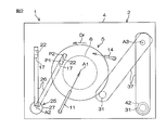
- FIG. 2 is a schematic plan view of the processing unit 2.
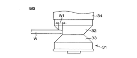
- FIG. 3 is a schematic view of the brush 31 pressed against the outer peripheral portion of the substrate W when viewed horizontally.
- the substrate processing apparatus 1 is an apparatus for spray cleaning and scrub cleaning of the upper surface and outer periphery of a disk-shaped substrate W such as a semiconductor wafer.
- the substrate processing apparatus 1 includes a single wafer processing unit 2 that processes substrates W one by one, a transfer robot (not shown) that transfers the substrate W to the processing unit 2, and a control device that controls the substrate processing apparatus 1. 3 is included.
- the control device 3 is a computer including a calculation unit and a storage unit.
- the processing unit 2 includes a box-shaped chamber 4 having an internal space, and a spin chuck 5 that rotates around a vertical rotation axis A1 that passes through a central portion of the substrate W while holding a single substrate W horizontally in the chamber 4. And a cylindrical cup (not shown) for receiving the processing liquid discharged from the substrate W held on the spin chuck 5.
- the spin chuck 5 is an example of a substrate holding unit.
- the spin chuck 5 has a disk-shaped spin base 6 having an outer diameter smaller than that of the substrate W, and a lower surface (back surface) of the substrate W adsorbed to a suction port opened on the upper surface of the spin base 6. And a suction device 8 for holding W horizontally.
- the spin chuck 5 further includes a spin motor 7 that rotates the substrate W and the spin base 6 in a rotation direction Dr that is a direction around the rotation axis A1.
- the processing unit 2 includes an upper surface nozzle 11 that discharges a processing liquid toward the center of the upper surface of the substrate W held by the spin chuck 5, and a spin base 6 in the lower surface of the substrate W held by the spin chuck 5. And a lower surface nozzle 14 that discharges the processing liquid toward the surrounding positions.
- the upper surface nozzle 11 is connected to an upper surface pipe 12 in which an upper surface valve 13 is interposed.
- the lower surface nozzle 14 is connected to a lower surface pipe 15 in which a lower surface valve 16 is interposed.
- the treatment liquid is not limited to the rinse liquid, and may be a chemical liquid such as ammonia water or a mixed liquid of ammonia water and hydrogen peroxide water. Different types of processing liquids may be supplied to the upper surface nozzle 11 and the lower surface nozzle 14.
- the processing unit 2 includes a spray nozzle 17 that causes a plurality of droplets to collide with the upper surface of the substrate W held by the spin chuck 5, and a collision position P1 within the upper surface of the substrate W that the plurality of droplets collide (see FIG. 2).
- the cover rinse liquid nozzle 22 for forming a liquid film covering the cover) and the nozzle moving mechanism 25 for moving the spray nozzle 17 and the cover rinse liquid nozzle 22 are included.
- the spray nozzle 17 is a two-fluid nozzle that generates a plurality of droplets that scatter downward toward the upper surface of the substrate W by colliding liquid and gas inside or outside thereof.
- the two-fluid nozzle includes a liquid discharge port that discharges liquid toward the upper surface of the substrate W, and a gas discharge port that discharges gas that collides with the liquid discharged from the liquid discharge port.
- the spray nozzle 17 may generate a plurality of droplets by simultaneously ejecting liquid from a plurality of holes.
- the plurality of droplets generated by the spray nozzle 17 collide with the collision position P1 in the upper surface of the substrate W.
- the collision position P1 is, for example, a region in the upper surface of the substrate W covered with the spray nozzle 17 in plan view.
- the spray nozzle 17 When the spray nozzle 17 is a two-fluid nozzle, the spray nozzle 17 is connected to a liquid pipe 18 provided with a liquid valve 19 and a gas pipe 20 provided with a gas valve 21. When the liquid valve 19 and the gas valve 21 are opened, the liquid and gas are supplied to the spray nozzle 17, and a plurality of droplets are generated that scatter downward toward the upper surface of the substrate W.
- the liquid supplied to the spray nozzle 17 is pure water, and the gas supplied to the spray nozzle 17 is nitrogen gas.
- the liquid supplied to the spray nozzle 17 may be a treatment liquid other than pure water.
- the gas supplied to the spray nozzle 17 may be an inert gas other than nitrogen gas.
- the cover rinse liquid nozzle 22 is connected to a cover rinse liquid pipe 23 in which a cover rinse liquid valve 24 is interposed. When the cover rinse liquid valve 24 is opened, the cover rinse liquid is discharged from the cover rinse liquid nozzle 22 and supplied to the upper surface of the substrate W.
- the cover rinse liquid is pure water.
- the cover rinse liquid may be a treatment liquid other than pure water.
- the cover rinse liquid nozzle 22 discharges the cover rinse liquid toward the liquid landing position P2 (see FIG. 2) in the upper surface of the substrate W.
- the cover rinse liquid deposited on the liquid deposition position P2 forms a liquid film smaller than the substrate W covering the liquid deposition position P2.
- the liquid film formed on the rotating substrate W moves in the rotation direction Dr of the substrate W. With respect to the rotation direction Dr of the substrate W, the liquid landing position P2 is a position upstream of the collision position P1.
- the nozzle moving mechanism 25 includes a nozzle arm 26 to which the spray nozzle 17 and the cover rinse liquid nozzle 22 are attached at the tip, and a nozzle arm along a path through which the tip of the nozzle arm 26 passes through the center of the substrate W in plan view. And a nozzle horizontal drive mechanism 27 that moves the nozzle 26 horizontally.
- the nozzle horizontal drive mechanism 27 rotates the nozzle arm 26 horizontally around the vertical nozzle rotation axis A2 located around the spin chuck 5 and the cup.
- the nozzle horizontal drive mechanism 27 moves the spray nozzle 17 and the cover rinse liquid nozzle 22 horizontally by rotating the nozzle arm 26 horizontally.
- the nozzle horizontal drive mechanism 27 includes a processing position where the spray nozzle 17 and the cover rinse liquid nozzle 22 are positioned above the substrate W, and the spray nozzle 17 and the cover rinse liquid nozzle 22 are positioned around the spin chuck 5 and the cup in plan view. The spray nozzle 17 and the cover rinse liquid nozzle 22 are moved horizontally between the standby positions.
- the liquid landing position P2 and the collision position P1 are close to the rotation direction Dr of the substrate W.
- the liquid landing position P2 is a position upstream of the collision position P1.
- the processing unit 2 includes a brush 31 that is pressed against the outer peripheral portion of the substrate W, a brush arm 37 that holds the brush 31, and a brush moving mechanism that moves the brush 31 by moving the brush arm 37. 38.
- the processing unit 2 may include a brush rotation mechanism 41 that rotates the brush 31 around a vertical center line of the brush 31 with respect to the brush arm 37 in the brush arm 37.
- the brush 31 is held by a brush holder 34 disposed above the brush 31.
- the brush holder 34 is attached to a holder attachment portion 35 disposed above the brush holder 34.
- the holder mounting portion 35 is supported by a support shaft 36 that extends upward from the holder mounting portion 35.
- the support shaft 36 protrudes downward from the brush arm 37.
- the brush 31 is an elastically deformable sponge brush made of a synthetic resin such as PVA (polyvinyl alcohol).
- the drum-shaped brush 31 includes a frustoconical upper cleaning surface 32 that becomes thinner as it approaches the lower end, and a frustoconical lower cleaning surface 33 that becomes thinner as it approaches the upper end.
- the upper cleaning surface 32 and the lower cleaning surface 33 are connected to each other at the lower end of the upper cleaning surface 32 and the upper end of the lower cleaning surface 33, and have shapes symmetrical to each other with respect to a horizontal plane passing through the connecting portion therebetween.
- the tapered upper cleaning surface 32 and lower cleaning surface 33 form an annular groove having a V-shaped cross section that is recessed toward the vertical center line of the brush 31.
- the brush moving mechanism 38 includes a brush horizontal drive mechanism 39 that moves the brush arm 37 horizontally and a brush vertical drive mechanism 40 that moves the brush arm 37 vertically.
- FIG. 2 shows an example in which the brush horizontal drive mechanism 39 is a brush turning mechanism for turning the brush arm 37 around the vertical brush turning axis A3 located around the spin chuck 5 and the cup.
- the brush horizontal drive mechanism 39 may be a brush slide mechanism that horizontally translates the brush arm 37.
- the brush moving mechanism 38 moves the brush to a plurality of positions by moving the brush arm 37.
- the plurality of positions include an upper cleaning position where the upper cleaning surface 32 of the brush 31 is pressed against the outer peripheral portion of the substrate W, a lower cleaning position where the lower cleaning surface 33 of the brush 31 is pressed against the outer peripheral portion of the substrate W, and the brush 31 And a standby position positioned around the spin chuck 5 and the cup in plan view.
- the plurality of positions further includes an upper proximity position where the upper cleaning surface 32 of the brush 31 horizontally faces the outer peripheral portion of the substrate W, and a lower proximity where the lower cleaning surface 33 of the brush 31 horizontally faces the outer peripheral portion of the substrate W. And location.
- FIG. 4 is an enlarged view for explaining the outer peripheral portion of the substrate W.
- the upper surface of the substrate W includes a horizontal and flat circular upper surface flat portion and an annular upper surface inclined portion that extends obliquely downward from the outer end of the upper surface flat portion.
- the lower surface of the substrate W includes a horizontal and flat circular lower surface flat portion, and an annular lower surface inclined portion that extends obliquely upward from the outer end of the lower surface flat portion.
- the upper surface inclined portion and the lower surface inclined portion are inclined with respect to the upper surface flat portion and the lower surface flat portion.
- the annular tip of the substrate W extends from the outer end of the upper inclined portion to the outer end of the lower inclined portion.
- the outer peripheral portion (so-called bevel portion) of the substrate W is a portion including the upper surface inclined portion, the tip, and the lower surface inclined portion.
- FIG. 4 shows an example in which the outer peripheral portion of the substrate W has a parabolic cross section.
- the outer peripheral portion of the substrate W is not limited to a parabolic cross section, but may be a trapezoidal cross section. That is, each of the upper surface inclined portion, the tip, and the lower surface inclined portion is not limited to the circular arc shape in cross section, and may be linear in cross section.
- the upper surface of the substrate W is a surface corresponding to the device forming surface, a part of the upper flat portion corresponds to the device forming region.
- the non-device formation region is an annular region around the device formation region in the upper surface of the substrate W.
- the brush 31 When the brush 31 is arranged at the upper cleaning position (position shown in FIG. 7), the upper cleaning surface 32 of the brush 31 is pressed against the outer peripheral portion of the substrate W, and the outer peripheral portion of the substrate W bites into the brush 31. As a result, the tip of the substrate W and the upper inclined surface come into contact with the brush 31. Similarly, when the brush 31 is disposed at the lower cleaning position (position shown in FIG. 6), the lower cleaning surface 33 of the brush 31 is pressed against the outer peripheral portion of the substrate W, and the outer peripheral portion of the substrate W bites into the brush 31. As a result, the tip of the substrate W and the lower surface inclined portion come into contact with the brush 31.
- the cleaning width W1 means a horizontal distance from the tip of the substrate W to the inner periphery of the annular region where the brush 31 and the substrate W are in contact with each other.
- the cleaning width W1 is, for example, a value exceeding 0 and not exceeding 5 mm.
- the cleaning width W1 varies according to the pressing force (or pressing amount) of the brush 31 against the substrate W.
- the outer peripheral portions of the upper surface flat portion and the lower surface flat portion of the substrate W also contact the brush 31.
- the outer peripheral portion of the upper flat portion of the substrate W is a non-device forming region.
- the control device 3 controls the substrate processing apparatus 1 based on the recipe indicating the processing conditions and processing procedures of the substrate W, thereby causing the substrate processing apparatus 1 to process the substrate W under the processing conditions specified in the recipe.
- the cleaning width W1 is specified in the recipe.
- the control device 3 adjusts the pressing force or pressing amount of the brush 31 against the substrate W by controlling at least one of the brush horizontal driving mechanism 39 and the brush vertical driving mechanism 40 based on the recipe. . As a result, the outer peripheral portion of the substrate W is scrub cleaned with the cleaning width W1 specified in the recipe.
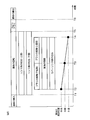
- FIG. 5 is a time chart for explaining an example of the processing of the substrate W performed by the processing unit 2.
- the discharge of the rinsing liquid is illustrated to start simultaneously with the rotation of the substrate W, but the discharge of the rinsing liquid may be started before or after the rotation of the substrate W is started.
- the following operations are executed by the control device 3 controlling the substrate processing apparatus 1.
- the substrate W to be processed may be a substrate W whose pattern is exposed on the surface or a substrate W whose pattern is not exposed.
- a transfer robot (not shown) loads the substrate W on the hand into the chamber 4 and puts the substrate W with the surface facing upward on the spin base 6. Put. Thereafter, the suction device 8 of the spin chuck 5 adsorbs the substrate W on the spin base 6 to the spin base 6. Subsequently, the spin motor 7 starts to rotate the substrate W and the spin base 6 (time T1). Thereby, the substrate W rotates at a cleaning speed (for example, 100 to 300 rpm). Thereafter, the upper surface valve 13 and the lower surface valve 16 are opened, and the upper surface nozzle 11 and the lower surface nozzle 14 discharge pure water. Thereby, the supply of pure water to the upper surface and the lower surface of the substrate W is started (time T1).
- a cleaning speed for example, 100 to 300 rpm
- the brush moving mechanism 38 moves the brush 31 from the standby position to the lower proximity position. Thereby, the lower cleaning surface 33 of the brush 31 is horizontally opposed to the outer peripheral portion of the substrate W. Thereafter, the brush moving mechanism 38 moves the brush 31 from the lower proximity position to the lower contact position by moving the brush 31 horizontally toward the outer peripheral portion of the substrate W. As a result, the lower cleaning surface 33 of the brush 31 is pressed against the outer periphery of the substrate W (time T2). While the lower cleaning surface 33 of the brush 31 is pressed against the outer peripheral portion of the substrate W, the brush 31 may be rotationally driven in the normal rotation direction or the reverse rotation direction, or may be fixed in the rotation direction of the brush 31. Good.
- the outer peripheral portion of the substrate W bites into the lower cleaning surface 33, and the tip and lower surface inclined portions of the substrate W come into contact with the brush 31.
- the outer peripheral portion of the lower flat portion of the substrate W also contacts the brush 31.
- the brush 31 is rubbed around the entire circumference of the substrate W by the rotation of the substrate W. For this reason, particles adhering to the lower inclined portion or the like of the substrate W are peeled off by a physical force from the brush 31. The peeled particles are washed away by pure water supplied from the lower surface nozzle 14 to the lower surface of the substrate W. As a result, the lower inclined portion and the like of the substrate W are cleaned.
- the nozzle moving mechanism 25 moves the spray nozzle 17 and the cover rinse liquid nozzle 22 located at the standby position to a central position where the spray nozzle 17 faces the center of the upper surface of the substrate W. Thereafter, the cover rinse liquid valve 24 is opened, and the cover rinse liquid nozzle 22 discharges pure water (time T2). Further, the gas valve 21 and the liquid valve 19 are opened, and the spray nozzle 17 ejects a plurality of droplets toward the center of the upper surface of the substrate W (time T2).
- the plurality of droplets ejected from the spray nozzle 17 collide with the upper surface of the substrate W covered with the pure water liquid film discharged from the cover rinse liquid nozzle 22. Therefore, the particles adhering to the upper surface of the substrate W are peeled off by a physical force due to the collision of the droplets. The peeled particles are washed away with pure water supplied from the cover rinse liquid nozzle 22 to the upper surface of the substrate W.
- the nozzle moving mechanism 25 moves the spray nozzle 17 horizontally when the lower cleaning surface 33 of the brush 31 is pressed against the outer peripheral portion of the substrate W, so that a plurality of droplets collide with the upper surface of the substrate W. Is moved from the center of the substrate W toward the middle of the substrate W (time T2-time T3).
- the middle of the substrate W is, for example, a position where the radial distance from the center of the substrate W to the middle of the substrate W is 2/3 of the radius of the substrate W.
- the middle of the substrate W may be a position that bisects the radius of the substrate W, or may be a position that is biased toward the center or the outer periphery of the substrate W.
- the middle of the substrate W is set so that the area of the circular region from the center of the substrate W to the middle of the substrate W matches or substantially matches the area of the annular region from the middle of the substrate W to the outer periphery of the substrate W. It may be set.
- the nozzle moving mechanism 25 temporarily stops the movement of the spray nozzle 17.
- the brush moving mechanism 38 vertically lowers the brush 31 from the lower contact position to the upper contact position.
- the lower cleaning surface 33 of the brush 31 is separated from the outer peripheral portion of the substrate W, and the upper cleaning surface 32 of the brush 31 is pressed against the outer peripheral portion of the substrate W (time T3).
- the brush 31 may be rotationally driven in the normal rotation direction or the reverse rotation direction, or may be fixed in the rotation direction of the brush 31. Good.
- the outer peripheral portion of the substrate W bites into the upper cleaning surface 32, and the tip and upper surface inclined portion of the substrate W come into contact with the brush 31.
- the outer peripheral portion of the upper flat portion of the substrate W also contacts the brush 31.
- the brush 31 is rubbed around the entire circumference of the substrate W by the rotation of the substrate W. For this reason, particles adhering to the upper inclined portion or the like of the substrate W are peeled off by a physical force from the brush 31.
- the separated particles are washed away by pure water supplied from the upper surface nozzle 11 to the upper surface of the substrate W. As a result, the upper inclined portion and the like of the substrate W are cleaned.
- the nozzle moving mechanism 25 moves the spray nozzle 17 and the cover rinse liquid nozzle 22 horizontally, thereby changing the collision position of the plurality of droplets to the upper surface of the substrate W in the middle of the substrate W.
- the spray nozzle 17 reaches the outer peripheral position that opposes the outer peripheral portion of the upper surface of the substrate W (time T4), the gas valve 21 and the liquid valve 19 are closed, and the ejection of droplets from the spray nozzle 17 is stopped. Further, the cover rinse liquid valve 24 is closed, and the discharge of pure water from the cover rinse liquid nozzle 22 is stopped (time T4).
- the outer peripheral position is, for example, a position where a collision position of a plurality of droplets with respect to the upper surface of the substrate W is positioned in front of an annular region where the upper surface of the substrate W and the brush 31 are in contact (for example, 1 to 5 mm before). .
- the nozzle moving mechanism 25 moves the spray nozzle 17 and the cover rinse liquid nozzle 22 from the outer peripheral position to the standby position after the ejection of droplets is stopped.
- the brush moving mechanism 38 moves the brush 31 horizontally from the upper contact position to the upper proximity position. Thereby, the brush 31 leaves
- the brush moving mechanism 38 may move the brush 31 to the upper adjacent position at the same time as the ejection of the droplet from the spray nozzle 17 is stopped, or before or after the ejection of the droplet is stopped. You may move 31 to an upper proximity position. After the brush 31 has moved to the upper proximity position, the brush moving mechanism 38 moves the brush 31 from the upper proximity position to the standby position.
- the upper surface valve 13 and the lower surface valve 16 are closed after the droplet ejection is stopped and the brush 31 is separated from the substrate W. Thereby, the discharge of pure water from the upper surface nozzle 11 and the lower surface nozzle 14 is stopped (time T5). Thereafter, the spin motor 7 accelerates the substrate W in the rotation direction Dr, and rotates the substrate W at a drying speed (eg, several thousand rpm) faster than the cleaning speed (time T5—time T6). Thereby, the pure water adhering to the substrate W is shaken off around the substrate W, and the substrate W is dried.
- a drying speed eg, several thousand rpm
- the spin motor 7 stops the rotation of the substrate W (time T6). Thereafter, the suction device 8 of the spin chuck 5 releases the adsorption of the substrate W to the spin base 6. Subsequently, a transfer robot (not shown) lifts the substrate W on the spin base 6 with a hand, and unloads the substrate W from the chamber 4 together with the hand. Thereby, the processed substrate W is unloaded from the chamber 4.
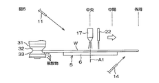
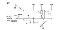
- FIG. 6 and 7 are schematic diagrams for explaining the positions of the brush 31 and the spray nozzle 17 during the processing of the substrate W.
- FIG. 6 and 7 are schematic diagrams for explaining the positions of the brush 31 and the spray nozzle 17 during the processing of the substrate W.
- the spray nozzle 17 causes the outer peripheral portion of the upper surface of the substrate W, that is, the scattered matter from the brush 31 to be scattered.
- a plurality of liquid droplets are ejected toward an area where the liquid drops easily. Therefore, even if the scattered matter from the brush 31 adheres to the upper surface of the substrate W, the scattered matter is immediately peeled off by the collision of the liquid droplets.
- the adherence time of the scattered object to the substrate W becomes longer, the scattered object tends to adhere to the substrate W and become difficult to remove. Accordingly, by immediately causing the droplets to collide with the scattered matter attached to the upper surface of the substrate W, the scattered matter can be reliably removed.
- the brush 31 is brought into contact with the lower inclined portion of the rotating substrate W. As a result, the brush 31 is rubbed around the entire circumference of the lower surface of the substrate W. Foreign substances such as particles are peeled off from the substrate W by a physical force from the brush 31.
- the plurality of droplets collide with a region in the upper surface of the substrate W between the center of the substrate W and the middle of the substrate W in parallel with the cleaning of the inclined portion on the lower surface of the substrate W. Foreign matters such as particles are peeled off from the substrate W by a physical force due to the collision of droplets.
- the brush 31 comes into contact with the upper surface inclined portion of the rotating substrate W. As a result, the brush 31 is rubbed around the entire circumference of the upper surface of the substrate W.
- the plurality of droplets collide with a region in the upper surface of the substrate W from the middle of the substrate W to the outer periphery of the substrate W in parallel with the cleaning of the upper inclined portion of the substrate W. In this way, the upper surface of the substrate W is physically cleaned in parallel with the physical cleaning of the outer peripheral portion of the substrate W, so that the cleanliness of the substrate W can be increased while suppressing an increase in cleaning time.
- an area where the scattered objects easily fall that is, an area in the upper surface of the substrate W from the middle of the substrate W to the outer periphery of the substrate W is when the brush 31 is in contact with the upper surface inclined portion of the substrate W.
- Washed with a plurality of droplets Therefore, the scattered matter adhering to the upper surface of the substrate W can be removed immediately. In this way, not only the foreign matter adhering to the outer peripheral portion of the upper surface of the substrate W but also scattered matter scattered from the brush 31 to the outer peripheral portion of the upper surface of the substrate W can be removed with a plurality of droplets. Can be further enhanced.
- the collision position of the plurality of droplets with respect to the upper surface of the substrate W moves from the center of the substrate W to the middle of the substrate W, and moves from the middle of the substrate W to the outer periphery of the substrate W.
- the collision position moves only to the outer peripheral side of the substrate W, a force for moving the foreign matter on the substrate W outward is generated. Therefore, the foreign matter on the substrate W is urged to move outward along the upper surface of the substrate W. Thereby, foreign substances can be efficiently removed from the substrate W, and the cleanliness of the substrate W can be further increased.
- the upper surface nozzle 11 discharges the rinsing liquid toward the center of the upper surface of the substrate W.
- the rinse liquid deposited on the upper surface of the substrate W flows outward along the upper surface of the substrate W.
- the foreign matter peeled off from the upper surface of the substrate W by the collision of the droplets is urged to move outward by the rinse liquid flowing outward. Therefore, foreign substances can be efficiently removed from the substrate W, and the cleanliness of the substrate W can be further increased.
- the collision position of the plurality of droplets with respect to the upper surface of the substrate W moves inside the region where the upper surface of the substrate W and the brush 31 are in contact with each other. That is, scrub cleaning (cleaning by the brush 31) and spray cleaning (cleaning by collision of droplets) are performed in different regions of the substrate W.
- scrub cleaning and spray cleaning are not performed on the same region of the substrate W, the cleaning time of the substrate W can be shortened.
- the brush 31 is not limited to a sponge brush, and may be a brush including a plurality of synthetic resin fibers.
- the collision position of the plurality of droplets with respect to the upper surface of the substrate W is moved only to the outer peripheral side of the substrate W
- the collision position may be moved to both the center side and the outer peripheral side of the substrate W.
- the spray nozzle 17 ejects a plurality of droplets.
- at least one of the upper surface nozzle 11 and the lower surface nozzle 14 may stop the discharge of pure water.
- the collision position of a plurality of droplets with respect to the upper surface of the substrate W is located between the middle of the substrate W and the outer periphery of the substrate W, at least one of the upper surface nozzle 11 and the lower surface nozzle 14 discharges pure water. You may stop.
- the cover rinse liquid nozzle 22 may stop the discharge of pure water.
- the cover rinse liquid nozzle 22 may stop the discharge of pure water while the collision position of the plurality of droplets with respect to the upper surface of the substrate W is located between the middle of the substrate W and the outer periphery of the substrate W. . Further, the cover rinse liquid nozzle 22 may be omitted.
- the scrub cleaning area and the spray cleaning area may partially overlap.
- the spray nozzle 17 may be moved until the collision position of the plurality of droplets with respect to the upper surface of the substrate W reaches the tip of the substrate W.
- the brush 31 is moved from the lower contact position to the upper contact position while moving the spray nozzle 17. It may be moved to a position.
- FIG. 5 shows that the movement speed of the collision position of the plurality of droplets with respect to the upper surface of the substrate W is constant, the movement speed of the collision position may not be constant.
Landscapes
- Cleaning Or Drying Semiconductors (AREA)
Abstract
ブラシを基板の下面傾斜部に接触させる下側スクラブ洗浄工程と並行して、複数の液滴を基板の上面に衝突させながら、基板の上面に対する複数の液滴の衝突位置を、基板の中央と基板の中間との間で移動させる中央側スプレー洗浄工程が行われる。その後、ブラシを基板の上面傾斜部に接触させる上側スクラブ洗浄工程と並行して、複数の液滴を基板の上面に衝突させながら、基板の上面に対する複数の液滴の衝突位置を、基板の中間と基板の外周との間で移動させる外周側スプレー洗浄工程が行われる。
Description
本発明は、基板を処理する基板処理方法および基板処理装置に関する。処理対象となる基板には、たとえば、半導体ウエハ、液晶表示装置用基板、プラズマディスプレイ用基板、FED(Field Emission Display)用基板、光ディスク用基板、磁気ディスク用基板、光磁気ディスク用基板、フォトマスク用基板、セラミック基板、太陽電池用基板などが含まれる。
特許文献1には、基板の外周部をブラシで洗浄する基板処理装置が開示されている。この基板処理装置は、基板を水平に保持しながら基板の中央部を通る鉛直な回転軸線まわりに回転させるスピンチャックと、スピンチャックに保持されている基板の外周部に鼓状のブラシを押し付けるブラシ移動機構とを備えている。ブラシは、回転している基板の下面外周部に押し付けられた後、回転している基板の上面外周部に押し付けられる。
特許文献1の基板処理装置では、ブラシが基板の外周部(いわゆるベベル部)に押し付けられるので、基板の外周部に付着している異物を物理的に除去することができる。しかしながら、特許文献1の構成では、基板の上面を物理的に洗浄することができない。
本発明者らは、回転している基板の外周部にブラシを接触させながら、複数の液滴を基板の上面に衝突させることにより、基板の外周部だけでなく、基板の上面も物理的に洗浄することを検討している。この場合、基板の外周部と基板の上面とが同時に洗浄されるので、基板の清浄度を高めながら、基板の洗浄時間を短縮できる。しかしながら、本発明者らは、基板の外周部および上面を単に同時に洗浄するだけでは、十分に清浄度を高めることができないおそれがあることを見出した。
そこで、本発明の目的の一つは、基板の洗浄時間の増加を抑えながら、基板の清浄度を高めることである。
本発明の一実施形態は、基板を水平に保持しながら前記基板を通る鉛直な回転軸線まわりに回転させる基板回転工程と、前記基板回転工程と並行して、ブラシを前記基板の下面傾斜部に接触させる下側スクラブ洗浄工程と、前記下側スクラブ洗浄工程と並行して、複数の液滴を前記基板の上面に衝突させながら、前記基板の上面に対する複数の液滴の衝突位置を、前記基板の中央と前記基板の中間との間で移動させる中央側スプレー洗浄工程と、前記下側スクラブ洗浄工程の後、前記基板回転工程と並行して、前記ブラシを前記基板の上面傾斜部に接触させる上側スクラブ洗浄工程と、前記上側スクラブ洗浄工程と並行して、複数の液滴を前記基板の上面に衝突させながら、前記基板の上面に対する複数の液滴の衝突位置を、前記基板の中間と前記基板の外周との間で移動させる外周側スプレー洗浄工程と、を含む、基板処理方法を提供する。
この方法によれば、回転している基板の下面傾斜部にブラシが接触する。これにより、基板の下面の全周にブラシが擦り付けられる。パーティクルなどの異物は、ブラシからの物理的な力により基板から剥がれる。複数の液滴は、基板の下面傾斜部の洗浄と並行して、基板の中央から基板の中間までの間の基板の上面内の領域に衝突する。パーティクルなどの異物は、液滴の衝突による物理的な力により基板から剥がれる。
基板の下面傾斜部が洗浄された後は、回転している基板の上面傾斜部にブラシが接触する。これにより、基板の上面の全周にブラシが擦り付けられる。複数の液滴は、基板の上面傾斜部の洗浄と並行して、基板の中間から基板の外周までの間の基板の上面内の領域に衝突する。このように、基板の外周部の物理的な洗浄と並行して、基板の上面を物理的に洗浄するので、洗浄時間の増加を抑えながら、基板の清浄度を高めることができる。
ブラシが回転している基板の下面傾斜部に接触しているとき、パーティクルや液滴など飛散物が、基板の下方でブラシから基板の回転軸線の方に下方に飛散する(図6参照)。これらの飛散物は、基板から離れる方向に飛散するので、基板に付着し難い。その一方で、ブラシが回転している基板の上面傾斜部に接触しているとき、ブラシから飛散した飛散物は、基板の上面に落下し易い(図7参照)。そのため、飛散物が、基板の上面、特に、基板の上面外周部に付着し易い。
飛散物が落下し易い領域、つまり、基板の中間から基板の外周までの間の基板の上面内の領域は、ブラシが基板の上面傾斜部に接触しているときに、複数の液滴で洗浄される。そのため、基板の上面に付着した飛散物を即座に除去できる。このように、基板の上面外周部に付着している異物だけでなく、ブラシから基板の上面外周部に飛散した飛散物も、複数の液滴で除去できるので、基板の清浄度をさらに高めることができる。
本実施形態において、以下の少なくとも一つの特徴が、前記基板処理方法に加えられてもよい。
前記中央側スプレー洗浄工程および外周側スプレー洗浄工程は、いずれも、前記基板の上面に対する複数の液滴の衝突位置を、前記基板の外周側だけに移動させる工程である。前記中央側スプレー洗浄工程は、前記基板の上面に対する複数の液滴の衝突位置を前記基板の中央から前記基板の中間に移動させる工程を1回以上行う工程である。同様に、前記外周側スプレー洗浄工程は、前記基板の上面に対する複数の液滴の衝突位置を前記基板の中間から前記基板の外周に移動させる工程を1回以上行う工程である。
この方法によれば、基板の上面に対する複数の液滴の衝突位置が、基板の外周側だけに移動するので、基板上の異物を外方に移動させる力が発生する。そのため、基板上の異物は、基板の上面に沿って外方に移動するように促される。これにより、異物を効率的に基板から除去することができ、基板の清浄度をさらに高めることができる。
前記基板処理方法は、前記中央側スプレー洗浄工程および外周側スプレー洗浄工程と並行して、前記基板の上面中央部に向けてリンス液を吐出する上リンス液供給工程をさらに含む。
この方法によれば、回転している基板の上面中央部に向けてリンス液が吐出される。基板の上面に着液したリンス液は、基板の上面に沿って外方に流れる。液滴の衝突によって基板の上面から剥がれた異物は、外方に流れるリンス液によって、外方に移動するように促される。そのため、異物を効率的に基板から除去することができ、基板の清浄度をさらに高めることができる。
前記外周側スプレー洗浄工程は、前記基板の上面と前記ブラシとが接触する領域の内側で、前記基板の上面に対する複数の液滴の衝突位置を、前記基板の中間と前記基板の外周との間で移動させる工程である。
この方法によれば、基板の上面に対する複数の液滴の衝突位置が、基板の上面とブラシとが接触する領域の内側で移動する。つまり、スクラブ洗浄(ブラシによる洗浄)とスプレー洗浄(液滴の衝突による洗浄)とが、基板の別々の領域に行われる。このように、スクラブ洗浄およびスプレー洗浄を基板の同じ領域に実行しないので、基板の洗浄時間を短縮できる。
本発明の他の実施形態は、基板を水平に保持しながら前記基板を通る鉛直な回転軸線まわりに回転させる基板保持ユニットと、前記基板に押し付けられるブラシと、前記ブラシが前記基板の下面傾斜部に接触する下接触位置と、前記ブラシが前記基板の上面傾斜部に接触する上接触位置と、を含む複数の位置に前記ブラシを移動させるブラシ移動機構と、前記基板の上面に衝突する複数の液滴を形成するスプレーノズルと、前記スプレーノズルを移動させることにより、前記基板の上面に対する複数の液滴の衝突位置を、前記基板の中央と前記基板の外周との間で移動させるノズル移動機構と、前記基板保持ユニット、ブラシ移動機構、およびノズル移動機構を制御する制御装置とを含む、基板処理装置を提供する。
前記制御装置は、前記基板保持ユニットに前記基板を水平に保持させ、前記回転軸線まわりに回転させる基板回転工程と、前記基板回転工程と並行して、前記ブラシ移動機構に前記ブラシを前記基板の下面傾斜部に接触させる下側スクラブ洗浄工程と、前記下側スクラブ洗浄工程と並行して、前記ノズル移動機構に、複数の液滴を前記基板の上面に衝突させながら、前記基板の上面に対する複数の液滴の衝突位置を、前記基板の中央と前記基板の中間との間で移動させる中央側スプレー洗浄工程と、前記下側スクラブ洗浄工程の後、前記基板回転工程と並行して、前記ブラシ移動機構に前記ブラシを前記基板の上面傾斜部に接触させる上側スクラブ洗浄工程と、前記上側スクラブ洗浄工程と並行して、前記ノズル移動機構に、複数の液滴を前記基板の上面に衝突させながら、前記基板の上面に対する複数の液滴の衝突位置を、前記基板の中間と前記基板の外周との間で移動させる外周側スプレー洗浄工程と、を実行する。この構成によれば、前述の効果を奏することができる。
本実施形態において、以下の少なくとも一つの特徴が、前記基板処理装置に加えられてもよい。
前記制御装置は、前記中央側スプレー洗浄工程および外周側スプレー洗浄工程のそれぞれにおいて、前記基板の上面に対する複数の液滴の衝突位置を、前記基板の外周側だけに移動させる。この構成によれば、前述の効果を奏することができる。
前記基板処理装置は、前記基板の上面中央部に向けてリンス液を吐出する上面ノズルをさらに含み、前記制御装置は、前記中央側スプレー洗浄工程および外周側スプレー洗浄工程と並行して、前記上面ノズルに前記基板の上面中央部に向けてリンス液を吐出させる上リンス液供給工程をさらに実行する。この構成によれば、前述の効果を奏することができる。
前記制御装置は、前記外周側スプレー洗浄工程において、前記ノズル移動機構に、前記基板の上面と前記ブラシとが接触する領域の内側で、前記基板の上面に対する複数の液滴の衝突位置を、前記基板の中間と前記基板の外周との間で移動させる。この構成によれば、前述の効果を奏することができる。
本発明における前述の、またはさらに他の目的、特徴および効果は、添付図面を参照して次に述べる実施形態の説明により明らかにされる。
図1は、本発明の一実施形態に係る基板処理装置1に備えられた処理ユニット2の内部を水平に見た模式図である。図2は、処理ユニット2の模式的な平面図である。図3は、基板Wの外周部に押し付けられているブラシ31を水平に見た模式図である。
図1に示すように、基板処理装置1は、半導体ウエハ等の円板状の基板Wの上面および外周部をスプレー洗浄およびスクラブ洗浄する装置である。基板処理装置1は、基板Wを一枚ずつ処理する枚葉式の処理ユニット2と、処理ユニット2に基板Wを搬送する搬送ロボット(図示せず)と、基板処理装置1を制御する制御装置3とを含む。制御装置3は、演算部と記憶部とを含むコンピュータである。
処理ユニット2は、内部空間を有する箱形のチャンバー4と、一枚の基板Wをチャンバー4内で水平に保持しながら基板Wの中央部を通る鉛直な回転軸線A1まわりに回転させるスピンチャック5と、スピンチャック5に保持されている基板Wから排出された処理液を受け止める筒状のカップ(図示せず)とを含む。スピンチャック5は、基板保持ユニットの一例である。
スピンチャック5は、基板Wよりも外径が小さい円板状のスピンベース6と、スピンベース6の上面で開口する吸引口に基板Wの下面(裏面)を吸着させることによりスピンベース6に基板Wを水平に保持させる吸引装置8とを含む。スピンチャック5は、さらに、回転軸線A1まわりの方向である回転方向Drに基板Wおよびスピンベース6を回転させるスピンモータ7を含む。
処理ユニット2は、スピンチャック5に保持されている基板Wの上面中央部に向けて処理液を吐出する上面ノズル11と、スピンチャック5に保持されている基板Wの下面内のスピンベース6のまわりの位置に向けて処理液を吐出する下面ノズル14とを含む。上面ノズル11は、上面バルブ13が介装された上面配管12に接続されている。下面ノズル14は、下面バルブ16が介装された下面配管15に接続されている。
上面バルブ13が開かれると、処理液が、上面ノズル11から吐出され、基板Wの上面に供給される。同様に、下面バルブ16が開かれると、処理液が、下面ノズル14から吐出され、基板Wの下面に供給される。上面ノズル11および下面ノズル14に供給される処理液は、リンス液の一例である純水(脱イオン水)である。リンス液は、純水に限らず、炭酸水、イオン水、オゾン水、還元水(水素水)または機能水(磁気水など)であってもよい。処理液は、リンス液に限らず、アンモニア水またはアンモニア水と過酸化水素水との混合液などの薬液であってもよい。互いに異なる種類の処理液が、上面ノズル11および下面ノズル14に供給されてもよい。
処理ユニット2は、スピンチャック5に保持されている基板Wの上面に複数の液滴を衝突させるスプレーノズル17と、複数の液滴が衝突する基板Wの上面内の衝突位置P1(図2参照)を覆う液膜を形成するカバーリンス液ノズル22と、スプレーノズル17およびカバーリンス液ノズル22を移動させるノズル移動機構25とを含む。
スプレーノズル17は、その内部または外部で液体と気体とを衝突させることにより、基板Wの上面に向かって下方に飛散する複数の液滴を生成する二流体ノズルである。二流体ノズルは、基板Wの上面に向けて液体を吐出する液体吐出口と、液体吐出口から吐出された液体に衝突する気体を吐出する気体吐出口とを含む。スプレーノズル17は、液体を複数の穴から同時に噴射することにより複数の液滴を生成してもよい。スプレーノズル17によって生成された複数の液滴は、基板Wの上面内の衝突位置P1に衝突する。衝突位置P1は、たとえば、平面視でスプレーノズル17に覆われる基板Wの上面内の領域である。
スプレーノズル17が二流体ノズルである場合、スプレーノズル17は、液体バルブ19が介装された液体配管18と、気体バルブ21が介装された気体配管20とに接続される。液体バルブ19および気体バルブ21が開かれると、液体および気体が、スプレーノズル17に供給され、基板Wの上面に向かって下方に飛散する複数の液滴が生成される。スプレーノズル17に供給される液体は、純水であり、スプレーノズル17に供給される気体は、窒素ガスである。スプレーノズル17に供給される液体は、純水以外の処理液であってもよい。スプレーノズル17に供給される気体は、窒素ガス以外の不活性ガスであってもよい。
カバーリンス液ノズル22は、カバーリンス液バルブ24が介装されたカバーリンス液配管23に接続されている。カバーリンス液バルブ24が開かれると、カバーリンス液が、カバーリンス液ノズル22から吐出され、基板Wの上面に供給される。カバーリンス液は、純水である。カバーリンス液は、純水以外の処理液であってもよい。カバーリンス液ノズル22は、基板Wの上面内の着液位置P2(図2参照)に向けてカバーリンス液を吐出する。着液位置P2に着液したカバーリンス液は、着液位置P2を覆う基板Wより小さな液膜を形成する。回転している基板W上に形成された液膜は、基板Wの回転方向Drに移動する。基板Wの回転方向Drに関して、着液位置P2は、衝突位置P1の上流の位置である。
ノズル移動機構25は、スプレーノズル17およびカバーリンス液ノズル22が先端部に取り付けられたノズルアーム26と、ノズルアーム26の先端部が平面視で基板Wの中央部を通る経路に沿ってノズルアーム26を水平に移動させるノズル水平駆動機構27とを含む。ノズル水平駆動機構27は、スピンチャック5およびカップの周囲に位置する鉛直なノズル回動軸線A2まわりにノズルアーム26を水平に回動させる。
図2に示すように、ノズル水平駆動機構27は、ノズルアーム26を水平に回動させることにより、スプレーノズル17およびカバーリンス液ノズル22を水平に移動させる。ノズル水平駆動機構27は、スプレーノズル17およびカバーリンス液ノズル22が基板Wの上方に位置する処理位置と、スプレーノズル17およびカバーリンス液ノズル22が平面視でスピンチャック5およびカップの周囲に位置する待機位置との間で、スプレーノズル17およびカバーリンス液ノズル22を水平に移動させる。
スプレーノズル17およびカバーリンス液ノズル22が同じノズルアーム26に保持されているので、着液位置P2および衝突位置P1は、基板Wの回転方向Drに近接している。基板Wの回転方向Drに関して、着液位置P2は、衝突位置P1の上流の位置である。カバーリンス液ノズル22がカバーリンス液を吐出しているときに、スプレーノズル17が複数の液滴を生成すると、複数の液滴は、カバーリンス液の液膜で覆われた衝突位置P1に衝突する。これにより、液滴の衝突によって基板Wに加わる衝撃が緩和されるので、パターン倒れの発生が抑制または防止される。
図1に示すように、処理ユニット2は、基板Wの外周部に押し付けられるブラシ31と、ブラシ31を保持するブラシアーム37と、ブラシアーム37を移動させることによりブラシ31を移動させるブラシ移動機構38とを含む。処理ユニット2は、ブラシアーム37に対してブラシ31の鉛直な中心線まわりにブラシ31を回転させるブラシ自転機構41をブラシアーム37内に備えていてもよい。
ブラシ31は、ブラシ31の上方に配置されたブラシホルダ34に保持されている。ブラシホルダ34は、ブラシホルダ34の上方に配置されたホルダ取付部35に取り付けられている。ホルダ取付部35は、ホルダ取付部35から上方に延びる支持軸36に支持されている。支持軸36は、ブラシアーム37から下方に突出している。ブラシ自転機構41がブラシアーム37に備えられる場合、ブラシ自転機構41は、支持軸36をその中心線まわりに回転させることにより、ブラシ31を自転させる。
図3に示すように、ブラシ31は、PVA(ポリビニルアルコール)などの合成樹脂で作成された弾性変形可能なスポンジブラシである。鼓状のブラシ31は、その下端に近づくにしたがって細くなる円錐台状の上洗浄面32と、その上端に近づくにしたがって細くなる円錐台状の下洗浄面33とを含む。上洗浄面32および下洗浄面33は、上洗浄面32の下端および下洗浄面33の上端で結合されており、両者の結合部を通る水平面に関して互いに対称な形状を有している。テーパー状の上洗浄面32および下洗浄面33は、ブラシ31の鉛直な中心線の方に凹んだ断面V字状の環状の溝を形成している。
図1に示すように、ブラシ移動機構38は、ブラシアーム37を水平に移動させるブラシ水平駆動機構39と、ブラシアーム37を鉛直に移動させるブラシ鉛直駆動機構40とを含む。図2は、ブラシ水平駆動機構39が、スピンチャック5およびカップの周囲に位置する鉛直なブラシ回動軸線A3まわりにブラシアーム37を回動させるブラシ旋回機構である例を示している。ブラシ水平駆動機構39は、ブラシアーム37を水平に平行移動させるブラシスライド機構であってもよい。
ブラシ移動機構38は、ブラシアーム37を移動させることにより、ブラシを複数の位置に移動させる。複数の位置は、ブラシ31の上洗浄面32が基板Wの外周部に押し付けられる上洗浄位置と、ブラシ31の下洗浄面33が基板Wの外周部に押し付けられる下洗浄位置と、ブラシ31が平面視でスピンチャック5およびカップの周囲に位置する待機位置とを含む。複数の位置は、さらに、ブラシ31の上洗浄面32が基板Wの外周部に水平に対向する上近接位置と、ブラシ31の下洗浄面33が基板Wの外周部に水平に対向する下近接位置とを含む。
処理ユニット2は、待機位置に位置するブラシ31を収容する筒状のポット42と、洗浄液の一例である純水をポット42内で吐出する洗浄液ノズル43とを含む。ブラシ移動機構38がブラシ31を待機位置に移動させると、ブラシ31は、ポット42内に収容される。ブラシ31に付着しているパーティクルなどの異物は、洗浄液ノズル43から吐出された純水によって除去される。また、待機位置に位置するブラシ31は、洗浄液ノズル43から吐出された純水によって湿潤状態に維持される。
図4は、基板Wの外周部について説明するための拡大図である。基板Wの上面は、水平で平坦な円形の上面平坦部と、上面平坦部の外端から斜め下に外方に延びる環状の上面傾斜部とを含む。同様に、基板Wの下面は、水平で平坦な円形の下面平坦部と、下面平坦部の外端から斜め上に外方に延びる環状の下面傾斜部とを含む。上面傾斜部および下面傾斜部は、上面平坦部および下面平坦部に対して傾いている。基板Wの環状の先端は、上面傾斜部の外端から下面傾斜部の外端まで延びている。
基板Wの外周部(いわゆる、ベベル部)は、上面傾斜部、先端、および下面傾斜部を含む部分である。図4は、基板Wの外周部が断面放物線状である例を示している。基板Wの外周部は、断面放物線状に限らず、断面台形状であってもよい。つまり、上面傾斜部、先端、および下面傾斜部のそれぞれは、断面円弧状に限らず、断面直線状であってもよい。基板Wの上面がデバイス形成面に相当する表面である場合、上面平坦部の一部が、デバイス形成領域に相当する。非デバイス形成領域は、基板Wの上面内のデバイス形成領域のまわりの環状の領域である。
ブラシ31が上洗浄位置(図7に示す位置)に配置されると、ブラシ31の上洗浄面32が基板Wの外周部に押し付けられ、基板Wの外周部がブラシ31に食い込む。これにより、基板Wの先端および上面傾斜部が、ブラシ31に接触する。同様に、ブラシ31が下洗浄位置(図6に示す位置)に配置されると、ブラシ31の下洗浄面33が基板Wの外周部に押し付けられ、基板Wの外周部がブラシ31に食い込む。これにより、基板Wの先端および下面傾斜部が、ブラシ31に接触する。
回転している基板Wの外周部にブラシ31が押し付けられると、ブラシ31が基板Wの全周に擦り付けられる。洗浄幅W1(図3参照)は、基板Wの先端からブラシ31と基板Wとが接触する環状の領域の内周縁までの水平方向の距離を意味する。洗浄幅W1は、たとえば、0を超える5mm以下の値である。洗浄幅W1は、基板Wに対するブラシ31の押付力(または押付量)に応じて変化する。基板Wに対するブラシ31の押付力によっては、基板Wの上面平坦部および下面平坦部の外周部も、ブラシ31に接触する。基板Wの上面平坦部の外周部は、非デバイス形成領域である。
制御装置3は、基板Wの処理条件および処理手順を示すレシピに基づいて基板処理装置1を制御することにより、レシピで指定されている処理条件で基板処理装置1に基板Wを処理させる。洗浄幅W1は、レシピに指定されている。以下に説明するように、制御装置3は、レシピに基づいてブラシ水平駆動機構39およびブラシ鉛直駆動機構40の少なくとも一方を制御することにより、基板Wに対するブラシ31の押付力または押付量を調整する。これにより、レシピに指定されている洗浄幅W1で基板Wの外周部がスクラブ洗浄される。
図5は、処理ユニット2によって行われる基板Wの処理の一例について説明するためのタイムチャートである。
図5では、リンス液の吐出が基板Wの回転と同時に開始されるように描かれているが、リンス液の吐出は、基板Wの回転が開始される前または後に開始されてもよい。他の動作についても同様である。以下の各動作は、制御装置3が基板処理装置1を制御することにより実行される。処理される基板Wは、パターンが表面で露出した基板Wであってもよいし、パターンが露出してない基板Wであってもよい。
処理ユニット2によって基板Wが処理されるとき、搬送ロボット(図示せず)が、ハンド上の基板Wをチャンバー4内に搬入し、表面が上に向けられた基板Wをスピンベース6の上に置く。その後、スピンチャック5の吸引装置8が、スピンベース6上の基板Wをスピンベース6に吸着させる。続いて、スピンモータ7が、基板Wおよびスピンベース6の回転を開始させる(時刻T1)。これにより、基板Wが洗浄速度(たとえば、100~300rpm)で回転する。その後、上面バルブ13および下面バルブ16が開かれ、上面ノズル11および下面ノズル14が純水を吐出する。これにより、基板Wの上面および下面への純水の供給が開始される(時刻T1)。
次に、ブラシ移動機構38が、ブラシ31を待機位置から下近接位置に移動させる。これにより、ブラシ31の下洗浄面33が、基板Wの外周部に水平に対向する。その後、ブラシ移動機構38は、ブラシ31を基板Wの外周部の方に水平に移動させることにより、ブラシ31を下近接位置から下接触位置に移動させる。これにより、ブラシ31の下洗浄面33が基板Wの外周部に押し付けられる(時刻T2)。ブラシ31の下洗浄面33が基板Wの外周部に押し付けられている間、ブラシ31は、正転方向または逆転方向に回転駆動されてもよいし、ブラシ31の回転方向に固定されていてもよい。
ブラシ31の下洗浄面33が基板Wの外周部に押し付けられると、基板Wの外周部が下洗浄面33に食い込み、基板Wの先端および下面傾斜部がブラシ31に接触する。このとき、基板Wの下面平坦部の外周部もブラシ31に接触する。ブラシ31は、基板Wの回転により、基板Wの全周に擦り付けられる。そのため、基板Wの下面傾斜部等に付着しているパーティクルは、ブラシ31からの物理的な力により剥離される。剥離されたパーティクルは、下面ノズル14から基板Wの下面に供給された純水によって洗い流される。これにより、基板Wの下面傾斜部等が洗浄される。
一方、ノズル移動機構25は、待機位置に位置するスプレーノズル17およびカバーリンス液ノズル22を、スプレーノズル17が基板Wの上面中央部に対向する中央位置に移動させる。その後、カバーリンス液バルブ24が開かれ、カバーリンス液ノズル22が純水を吐出する(時刻T2)。さらに、気体バルブ21および液体バルブ19が開かれ、スプレーノズル17が基板Wの上面中央部に向けて複数の液滴を噴射する(時刻T2)。
スプレーノズル17から噴射された複数の液滴は、カバーリンス液ノズル22から吐出された純水の液膜で覆われている基板Wの上面に衝突する。そのため、基板Wの上面に付着しているパーティクルは、液滴の衝突による物理的な力により剥離される。剥離されたパーティクルは、カバーリンス液ノズル22から基板Wの上面に供給された純水によって洗い流される。
ノズル移動機構25は、ブラシ31の下洗浄面33が基板Wの外周部に押し付けられているときに、スプレーノズル17を水平に移動させることにより、基板Wの上面に対する複数の液滴の衝突位置を基板Wの中央から基板Wの中間の方に移動させる(時刻T2-時刻T3)。基板Wの中間は、たとえば、基板Wの中央から基板Wの中間までの半径方向の距離が基板Wの半径の2/3となる位置である。基板Wの中間は、基板Wの半径を二等分する位置であってもよいし、基板Wの中央または外周に偏った位置であってもよい。あるいは、基板Wの中央から基板Wの中間までの円形の領域の面積が、基板Wの中間から基板Wの外周までの環状の領域の面積に一致または概ね一致するように、基板Wの中間が設定されてもよい。
基板Wの上面に対する複数の液滴の衝突位置が基板Wの中間に達すると(時刻T3)、ノズル移動機構25は、スプレーノズル17の移動を一時的に停止させる。この状態で、ブラシ移動機構38は、ブラシ31を下接触位置から上接触位置に鉛直に下降させる。これにより、ブラシ31の下洗浄面33が基板Wの外周部から離れ、ブラシ31の上洗浄面32が基板Wの外周部に押し付けられる(時刻T3)。ブラシ31の上洗浄面32が基板Wの外周部に押し付けられている間、ブラシ31は、正転方向または逆転方向に回転駆動されてもよいし、ブラシ31の回転方向に固定されていてもよい。
ブラシ31の上洗浄面32が基板Wの外周部に押し付けられると、基板Wの外周部が上洗浄面32に食い込み、基板Wの先端および上面傾斜部がブラシ31に接触する。このとき、基板Wの上面平坦部の外周部もブラシ31に接触する。ブラシ31は、基板Wの回転により、基板Wの全周に擦り付けられる。そのため、基板Wの上面傾斜部等に付着しているパーティクルは、ブラシ31からの物理的な力により剥離される。剥離されたパーティクルは、上面ノズル11から基板Wの上面に供給された純水によって洗い流される。これにより、基板Wの上面傾斜部等が洗浄される。
ブラシ31が上接触位置に移動すると、ノズル移動機構25は、スプレーノズル17およびカバーリンス液ノズル22を水平に移動させることにより、基板Wの上面に対する複数の液滴の衝突位置を基板Wの中間から基板Wの外周の方に移動させる(時刻T3-時刻T4)。スプレーノズル17が基板Wの上面外周部に対向する外周位置に達すると(時刻T4)、気体バルブ21および液体バルブ19が閉じられ、スプレーノズル17からの液滴の噴射が停止される。さらに、カバーリンス液バルブ24が閉じられ、カバーリンス液ノズル22からの純水の吐出が停止される(時刻T4)。外周位置は、たとえば、基板Wの上面に対する複数の液滴の衝突位置が、基板Wの上面とブラシ31とが接触する環状の領域の手前(たとえば、1~5mm手前)に位置する位置である。ノズル移動機構25は、液滴の噴射が停止された後、スプレーノズル17およびカバーリンス液ノズル22を外周位置から待機位置に移動させる。
スプレーノズル17が外周位置に達すると、ブラシ移動機構38は、ブラシ31を上接触位置から上近接位置に水平に移動させる。これにより、ブラシ31が基板Wから離れる(時刻T4)。ブラシ移動機構38は、スプレーノズル17からの液滴の噴射が停止されるのと同時に、ブラシ31を上近接位置に移動させてもよいし、液滴の噴射が停止される前または後に、ブラシ31を上近接位置に移動させてもよい。ブラシ31が上近接位置に移動した後、ブラシ移動機構38は、ブラシ31を上近接位置から待機位置に移動させる。
上面バルブ13および下面バルブ16は、液滴の噴射が停止され、ブラシ31が基板Wから離れた後に閉じられる。これにより、上面ノズル11および下面ノズル14からの純水の吐出が停止される(時刻T5)。その後、スピンモータ7が、基板Wを回転方向Drに加速させ、洗浄速度よりも高速の乾燥速度(たとえば、数千rpm)で基板Wを回転させる(時刻T5-時刻T6)。これにより、基板Wに付着している純水が基板Wの周囲に振り切られ、基板Wが乾燥する。
基板Wの高速回転が開始されてから所定時間が経過すると、スピンモータ7が基板Wの回転を停止させる(時刻T6)。その後、スピンチャック5の吸引装置8が、スピンベース6への基板Wの吸着を解除する。続いて、搬送ロボット(図示せず)が、ハンドでスピンベース6上の基板Wを持ち上げ、ハンドと共に基板Wをチャンバー4から搬出する。これにより、処理済みの基板Wがチャンバー4から搬出される。
図6および図7は、基板Wの処理中におけるブラシ31およびスプレーノズル17の位置について説明するための模式図である。
図6に示すように、ブラシ31の下洗浄面33が回転している基板Wの外周部に押し付けられているとき、パーティクルや液滴などの飛散物が、基板Wの下方でブラシ31から回転軸線A1の方に下方に飛散する。これらの飛散物は、基板Wから離れる方向に飛散するので、基板Wに付着し難い。その一方で、図7に示すように、ブラシ31の上洗浄面32が回転している基板Wの外周部に押し付けられているとき、飛散物が、基板Wの上方でブラシ31から回転軸線A1の方に上方に飛散する。上方に飛散した飛散物は、基板W上に落下する。そのため、飛散物が、基板Wの上面、特に、基板Wの上面外周部に付着し易い。
前述のように、ブラシ31の上洗浄面32が回転している基板Wの外周部に押し付けられているとき、スプレーノズル17は、基板Wの上面外周部、つまり、ブラシ31からの飛散物が落下し易い領域に向けて複数の液滴を噴射している。そのため、ブラシ31からの飛散物が基板Wの上面に付着したとしても、この飛散物は、液滴の衝突により即座に剥離される。基板Wに対する飛散物の付着時間が長くなると、飛散物が基板Wに固着し取れ難くなる傾向がある。したがって、基板Wの上面に付着した飛散物に即座に液滴を衝突させることにより、当該飛散物を確実に除去することができる。
以上のように本実施形態では、回転している基板Wの下面傾斜部にブラシ31を接触させる。これにより、基板Wの下面の全周にブラシ31が擦り付けられる。パーティクルなどの異物は、ブラシ31からの物理的な力により基板Wから剥がれる。複数の液滴は、基板Wの下面傾斜部の洗浄と並行して、基板Wの中央から基板Wの中間までの間の基板Wの上面内の領域に衝突する。パーティクルなどの異物は、液滴の衝突による物理的な力により基板Wから剥がれる。
基板Wの下面傾斜部が洗浄された後は、回転している基板Wの上面傾斜部にブラシ31が接触する。これにより、基板Wの上面の全周にブラシ31が擦り付けられる。複数の液滴は、基板Wの上面傾斜部の洗浄と並行して、基板Wの中間から基板Wの外周までの間の基板Wの上面内の領域に衝突する。このように、基板Wの外周部の物理的な洗浄と並行して、基板Wの上面を物理的に洗浄するので、洗浄時間の増加を抑えながら、基板Wの清浄度を高めることができる。
さらに、飛散物が落下し易い領域、つまり、基板Wの中間から基板Wの外周までの間の基板Wの上面内の領域は、ブラシ31が基板Wの上面傾斜部に接触しているときに、複数の液滴で洗浄される。そのため、基板Wの上面に付着した飛散物を即座に除去できる。このように、基板Wの上面外周部に付着している異物だけでなく、ブラシ31から基板Wの上面外周部に飛散した飛散物も、複数の液滴で除去できるので、基板Wの清浄度をさらに高めることができる。
本実施形態によれば、基板Wの上面に対する複数の液滴の衝突位置が、基板Wの中央から基板Wの中間に移動し、基板Wの中間から基板Wの外周に移動する。このように、衝突位置が基板Wの外周側だけに移動するので、基板W上の異物を外方に移動させる力が発生する。そのため、基板W上の異物は、基板Wの上面に沿って外方に移動するように促される。これにより、異物を効率的に基板Wから除去することができ、基板Wの清浄度をさらに高めることができる。
本実施形態によれば、スプレーノズル17が基板Wの上面に向けて複数の液滴を噴射しているときに、上面ノズル11が基板Wの上面中央部に向けてリンス液を吐出する。基板Wの上面に着液したリンス液は、基板Wの上面に沿って外方に流れる。液滴の衝突によって基板Wの上面から剥がれた異物は、外方に流れるリンス液によって、外方に移動するように促される。そのため、異物を効率的に基板Wから除去することができ、基板Wの清浄度をさらに高めることができる。
本実施形態によれば、基板Wの上面に対する複数の液滴の衝突位置が、基板Wの上面とブラシ31とが接触する領域の内側で移動する。つまり、スクラブ洗浄(ブラシ31による洗浄)とスプレー洗浄(液滴の衝突による洗浄)とが、基板Wの別々の領域に行われる。このように、スクラブ洗浄およびスプレー洗浄を基板Wの同じ領域に実行しないので、基板Wの洗浄時間を短縮できる。
他の実施形態
本発明は、前述の実施形態の内容に限定されるものではなく、本発明の範囲内において種々の変更が可能である。
本発明は、前述の実施形態の内容に限定されるものではなく、本発明の範囲内において種々の変更が可能である。
たとえば、ブラシ31は、スポンジブラシに限らず、合成樹脂製の複数の繊維を備えるブラシであってもよい。
基板Wの上面に対する複数の液滴の衝突位置を、基板Wの外周側だけに移動させる場合について説明したが、基板Wの中央側および外周側の両方に衝突位置を移動させてもよい。
スプレーノズル17が複数の液滴を噴射している全期間に亘って、上面ノズル11および下面ノズル14が純水を吐出する場合について説明したが、スプレーノズル17が複数の液滴を噴射している期間の一部において、上面ノズル11および下面ノズル14の少なくとも一方が純水の吐出を停止してもよい。たとえば、基板Wの上面に対する複数の液滴の衝突位置が基板Wの中間と基板Wの外周との間に位置している間、上面ノズル11および下面ノズル14の少なくとも一方が純水の吐出を停止してもよい。
スプレーノズル17が複数の液滴を噴射している全期間に亘って、カバーリンス液ノズル22が純水を吐出する場合について説明したが、スプレーノズル17が複数の液滴を噴射している期間の一部において、カバーリンス液ノズル22が純水の吐出を停止してもよい。たとえば、基板Wの上面に対する複数の液滴の衝突位置が基板Wの中間と基板Wの外周との間に位置している間、カバーリンス液ノズル22が純水の吐出を停止してもよい。また、カバーリンス液ノズル22を省略してもよい。
スクラブ洗浄が行われるスクラブ洗浄領域とスプレー洗浄が行われるスプレー洗浄領域とが重ならない場合について説明したが、スクラブ洗浄領域およびスプレー洗浄領域が部分的に重なってもよい。たとえば、基板Wの上面に対する複数の液滴の衝突位置が、基板Wの先端に達するまで、スプレーノズル17を移動させてもよい。
ブラシ31を下接触位置から上接触位置に移動させるときに、スプレーノズル17の移動を一時的に停止させる場合について説明したが、スプレーノズル17を移動させながら、ブラシ31を下接触位置から上接触位置に移動させてもよい。
図5では、基板Wの上面に対する複数の液滴の衝突位置の移動速度が一定であるように示しているが、衝突位置の移動速度は一定でなくてもよい。
前述の全ての構成の2つ以上が組み合わされてもよい。前述の全ての工程の2つ以上が組み合わされてもよい。
この出願は、2015年9月28日に日本国特許庁に提出された特願2015-189833号に対応しており、この出願の全開示はここに引用により組み込まれるものとする。 本発明の実施形態について詳細に説明してきたが、これらは本発明の技術的内容を明らかにするために用いられた具体例に過ぎず、本発明はこれらの具体例に限定して解釈されるべきではなく、本発明の精神および範囲は添付の請求の範囲によってのみ限定される。
1 :基板処理装置
2 :処理ユニット
3 :制御装置
4 :チャンバー
5 :スピンチャック(基板保持ユニット)
6 :スピンベース
7 :スピンモータ
8 :吸引装置
11 :上面ノズル
12 :上面配管
13 :上面バルブ
14 :下面ノズル
15 :下面配管
16 :下面バルブ
17 :スプレーノズル
18 :液体配管
19 :液体バルブ
20 :気体配管
21 :気体バルブ
22 :カバーリンス液ノズル
23 :カバーリンス液配管
24 :カバーリンス液バルブ
25 :ノズル移動機構
26 :ノズルアーム
27 :ノズル水平駆動機構
31 :ブラシ
32 :上洗浄面
33 :下洗浄面
34 :ブラシホルダ
35 :ホルダ取付部
36 :支持軸
37 :ブラシアーム
38 :ブラシ移動機構
39 :ブラシ水平駆動機構
40 :ブラシ鉛直駆動機構
41 :ブラシ自転機構
42 :ポット
43 :洗浄液ノズル
A1 :回転軸線
A2 :ノズル回動軸線
A3 :ブラシ回動軸線
Dr :回転方向
P1 :衝突位置
P2 :着液位置
W :基板
W1 :洗浄幅
2 :処理ユニット
3 :制御装置
4 :チャンバー
5 :スピンチャック(基板保持ユニット)
6 :スピンベース
7 :スピンモータ
8 :吸引装置
11 :上面ノズル
12 :上面配管
13 :上面バルブ
14 :下面ノズル
15 :下面配管
16 :下面バルブ
17 :スプレーノズル
18 :液体配管
19 :液体バルブ
20 :気体配管
21 :気体バルブ
22 :カバーリンス液ノズル
23 :カバーリンス液配管
24 :カバーリンス液バルブ
25 :ノズル移動機構
26 :ノズルアーム
27 :ノズル水平駆動機構
31 :ブラシ
32 :上洗浄面
33 :下洗浄面
34 :ブラシホルダ
35 :ホルダ取付部
36 :支持軸
37 :ブラシアーム
38 :ブラシ移動機構
39 :ブラシ水平駆動機構
40 :ブラシ鉛直駆動機構
41 :ブラシ自転機構
42 :ポット
43 :洗浄液ノズル
A1 :回転軸線
A2 :ノズル回動軸線
A3 :ブラシ回動軸線
Dr :回転方向
P1 :衝突位置
P2 :着液位置
W :基板
W1 :洗浄幅
Claims (8)
- 基板を水平に保持しながら前記基板を通る鉛直な回転軸線まわりに回転させる基板回転工程と、
前記基板回転工程と並行して、ブラシを前記基板の下面傾斜部に接触させる下側スクラブ洗浄工程と、
前記下側スクラブ洗浄工程と並行して、複数の液滴を前記基板の上面に衝突させながら、前記基板の上面に対する複数の液滴の衝突位置を、前記基板の中央と前記基板の中間との間で移動させる中央側スプレー洗浄工程と、
前記下側スクラブ洗浄工程の後、前記基板回転工程と並行して、前記ブラシを前記基板の上面傾斜部に接触させる上側スクラブ洗浄工程と、
前記上側スクラブ洗浄工程と並行して、複数の液滴を前記基板の上面に衝突させながら、前記基板の上面に対する複数の液滴の衝突位置を、前記基板の中間と前記基板の外周との間で移動させる外周側スプレー洗浄工程と、を含む、基板処理方法。 - 前記中央側スプレー洗浄工程および外周側スプレー洗浄工程は、いずれも、前記基板の上面に対する複数の液滴の衝突位置を、前記基板の外周側だけに移動させる工程である、請求項1に記載の基板処理方法。
- 前記中央側スプレー洗浄工程および外周側スプレー洗浄工程と並行して、前記基板の上面中央部に向けてリンス液を吐出する上リンス液供給工程をさらに含む、請求項1または2に記載の基板処理方法。
- 前記外周側スプレー洗浄工程は、前記基板の上面と前記ブラシとが接触する領域の内側で、前記基板の上面に対する複数の液滴の衝突位置を、前記基板の中間と前記基板の外周との間で移動させる工程である、請求項1~3のいずれか一項に記載の基板処理方法。
- 基板を水平に保持しながら前記基板を通る鉛直な回転軸線まわりに回転させる基板保持ユニットと、
前記基板に押し付けられるブラシと、
前記ブラシが前記基板の下面傾斜部に接触する下接触位置と、前記ブラシが前記基板の上面傾斜部に接触する上接触位置と、を含む複数の位置に前記ブラシを移動させるブラシ移動機構と、
前記基板の上面に衝突する複数の液滴を形成するスプレーノズルと、
前記スプレーノズルを移動させることにより、前記基板の上面に対する複数の液滴の衝突位置を、前記基板の中央と前記基板の外周との間で移動させるノズル移動機構と、
前記基板保持ユニット、ブラシ移動機構、およびノズル移動機構を制御する制御装置とを含み、
前記制御装置は、
前記基板保持ユニットに前記基板を水平に保持させ、前記回転軸線まわりに回転させる基板回転工程と、
前記基板回転工程と並行して、前記ブラシ移動機構に前記ブラシを前記基板の下面傾斜部に接触させる下側スクラブ洗浄工程と、
前記下側スクラブ洗浄工程と並行して、前記ノズル移動機構に、複数の液滴を前記基板の上面に衝突させながら、前記基板の上面に対する複数の液滴の衝突位置を、前記基板の中央と前記基板の中間との間で移動させる中央側スプレー洗浄工程と、
前記下側スクラブ洗浄工程の後、前記基板回転工程と並行して、前記ブラシ移動機構に前記ブラシを前記基板の上面傾斜部に接触させる上側スクラブ洗浄工程と、
前記上側スクラブ洗浄工程と並行して、前記ノズル移動機構に、複数の液滴を前記基板の上面に衝突させながら、前記基板の上面に対する複数の液滴の衝突位置を、前記基板の中間と前記基板の外周との間で移動させる外周側スプレー洗浄工程と、を実行する、基板処理装置。 - 前記制御装置は、前記中央側スプレー洗浄工程および外周側スプレー洗浄工程のそれぞれにおいて、前記基板の上面に対する複数の液滴の衝突位置を、前記基板の外周側だけに移動させる、請求項5に記載の基板処理装置。
- 前記基板処理装置は、前記基板の上面中央部に向けてリンス液を吐出する上面ノズルをさらに含み、
前記制御装置は、前記中央側スプレー洗浄工程および外周側スプレー洗浄工程と並行して、前記上面ノズルに前記基板の上面中央部に向けてリンス液を吐出させる上リンス液供給工程をさらに実行する、請求項5または6に記載の基板処理装置。 - 前記制御装置は、前記外周側スプレー洗浄工程において、前記ノズル移動機構に、前記基板の上面と前記ブラシとが接触する領域の内側で、前記基板の上面に対する複数の液滴の衝突位置を、前記基板の中間と前記基板の外周との間で移動させる、請求項5~7のいずれか一項に記載の基板処理装置。
Priority Applications (4)
| Application Number | Priority Date | Filing Date | Title |
|---|---|---|---|
| US15/759,545 US10546763B2 (en) | 2015-09-28 | 2016-04-22 | Substrate treatment method and substrate treatment device |
| KR1020187006498A KR20180035902A (ko) | 2015-09-28 | 2016-04-22 | 기판 처리 방법 및 기판 처리 장치 |
| KR1020207000344A KR102316901B1 (ko) | 2015-09-28 | 2016-04-22 | 기판 처리 방법 및 기판 처리 장치 |
| CN201680053173.7A CN108028191B (zh) | 2015-09-28 | 2016-04-22 | 基板处理方法及基板处理装置 |
Applications Claiming Priority (2)
| Application Number | Priority Date | Filing Date | Title |
|---|---|---|---|
| JP2015189833A JP6508721B2 (ja) | 2015-09-28 | 2015-09-28 | 基板処理方法および基板処理装置 |
| JP2015-189833 | 2015-09-28 |
Publications (1)
| Publication Number | Publication Date |
|---|---|
| WO2017056540A1 true WO2017056540A1 (ja) | 2017-04-06 |
Family
ID=58423378
Family Applications (1)
| Application Number | Title | Priority Date | Filing Date |
|---|---|---|---|
| PCT/JP2016/062744 Ceased WO2017056540A1 (ja) | 2015-09-28 | 2016-04-22 | 基板処理方法および基板処理装置 |
Country Status (6)
| Country | Link |
|---|---|
| US (1) | US10546763B2 (ja) |
| JP (1) | JP6508721B2 (ja) |
| KR (2) | KR102316901B1 (ja) |
| CN (1) | CN108028191B (ja) |
| TW (1) | TWI595545B (ja) |
| WO (1) | WO2017056540A1 (ja) |
Families Citing this family (6)
| Publication number | Priority date | Publication date | Assignee | Title |
|---|---|---|---|---|
| TWI566955B (zh) * | 2015-11-03 | 2017-01-21 | 研能科技股份有限公司 | 多色列印墨匣 |
| JP6966917B2 (ja) | 2017-10-12 | 2021-11-17 | 株式会社Screenホールディングス | 基板処理方法および基板処理装置 |
| TWI834489B (zh) * | 2017-12-13 | 2024-03-01 | 日商東京威力科創股份有限公司 | 基板處理裝置 |
| CN110767536A (zh) * | 2019-10-30 | 2020-02-07 | 上海华力微电子有限公司 | 晶圆清洗方法 |
| US12509438B2 (en) | 2020-01-13 | 2025-12-30 | Aptabio Therapeutics Inc. | Pyrazole derivative |
| JP2024064210A (ja) * | 2022-10-27 | 2024-05-14 | 株式会社Screenホールディングス | 基板処理方法及び基板処理装置 |
Citations (2)
| Publication number | Priority date | Publication date | Assignee | Title |
|---|---|---|---|---|
| JP2009238938A (ja) * | 2008-03-26 | 2009-10-15 | Dainippon Screen Mfg Co Ltd | 基板処理装置 |
| JP2012094602A (ja) * | 2010-10-25 | 2012-05-17 | Tokyo Electron Ltd | ブラシ、基板処理装置および基板処理方法。 |
Family Cites Families (10)
| Publication number | Priority date | Publication date | Assignee | Title |
|---|---|---|---|---|
| JPH0864568A (ja) * | 1994-08-23 | 1996-03-08 | Toshiba Corp | ウェーハ洗浄装置 |
| US6594847B1 (en) * | 2000-03-28 | 2003-07-22 | Lam Research Corporation | Single wafer residue, thin film removal and clean |
| JP4719052B2 (ja) | 2006-03-30 | 2011-07-06 | ソニー株式会社 | 基板処理装置および基板処理方法 |
| JP4755519B2 (ja) * | 2006-03-30 | 2011-08-24 | 大日本スクリーン製造株式会社 | 基板処理装置および基板処理方法 |
| KR100892809B1 (ko) | 2006-03-30 | 2009-04-10 | 다이닛뽕스크린 세이조오 가부시키가이샤 | 기판처리장치 및 기판처리방법 |
| JP4719051B2 (ja) * | 2006-03-30 | 2011-07-06 | ソニー株式会社 | 基板処理装置および基板処理方法 |
| KR100940136B1 (ko) | 2006-08-29 | 2010-02-03 | 다이닛뽕스크린 세이조오 가부시키가이샤 | 기판처리방법 및 기판처리장치 |
| JP4976949B2 (ja) | 2007-07-26 | 2012-07-18 | 大日本スクリーン製造株式会社 | 基板処理装置 |
| JP2009206360A (ja) * | 2008-02-28 | 2009-09-10 | Dainippon Screen Mfg Co Ltd | 基板処理装置 |
| JP2010114123A (ja) | 2008-11-04 | 2010-05-20 | Tokyo Electron Ltd | 基板処理装置及び基板洗浄方法 |
-
2015
- 2015-09-28 JP JP2015189833A patent/JP6508721B2/ja active Active
-
2016
- 2016-04-22 US US15/759,545 patent/US10546763B2/en active Active
- 2016-04-22 KR KR1020207000344A patent/KR102316901B1/ko active Active
- 2016-04-22 KR KR1020187006498A patent/KR20180035902A/ko not_active Ceased
- 2016-04-22 WO PCT/JP2016/062744 patent/WO2017056540A1/ja not_active Ceased
- 2016-04-22 CN CN201680053173.7A patent/CN108028191B/zh active Active
- 2016-05-16 TW TW105115042A patent/TWI595545B/zh active
Patent Citations (2)
| Publication number | Priority date | Publication date | Assignee | Title |
|---|---|---|---|---|
| JP2009238938A (ja) * | 2008-03-26 | 2009-10-15 | Dainippon Screen Mfg Co Ltd | 基板処理装置 |
| JP2012094602A (ja) * | 2010-10-25 | 2012-05-17 | Tokyo Electron Ltd | ブラシ、基板処理装置および基板処理方法。 |
Also Published As
| Publication number | Publication date |
|---|---|
| TW201712742A (zh) | 2017-04-01 |
| KR20200004471A (ko) | 2020-01-13 |
| JP6508721B2 (ja) | 2019-05-08 |
| US10546763B2 (en) | 2020-01-28 |
| CN108028191B (zh) | 2022-02-22 |
| KR102316901B1 (ko) | 2021-10-22 |
| JP2017069262A (ja) | 2017-04-06 |
| KR20180035902A (ko) | 2018-04-06 |
| US20190157117A1 (en) | 2019-05-23 |
| CN108028191A (zh) | 2018-05-11 |
| TWI595545B (zh) | 2017-08-11 |
Similar Documents
| Publication | Publication Date | Title |
|---|---|---|
| US7803230B2 (en) | Substrate cleaning apparatus, substrate cleaning method, and medium for recording program used for the method | |
| JP4976949B2 (ja) | 基板処理装置 | |
| US10546763B2 (en) | Substrate treatment method and substrate treatment device | |
| KR102482211B1 (ko) | 기판 처리 장치, 기판 처리 방법 및 기억 매체 | |
| US20170047219A1 (en) | Substrate processing apparatus, substrate processing method, and computer-readable recording medium having stored thereon substrate processing program | |
| US9892955B2 (en) | Substrate holding/rotating device, substrate processing apparatus including the same, and substrate processing method | |
| JP6718714B2 (ja) | 基板処理方法および基板処理装置 | |
| US9768042B2 (en) | Substrate processing method and substrate processing apparatus | |
| TW201628114A (zh) | 液處理方法、記憶媒體及液處理裝置 | |
| CN108573897B (zh) | 基板处理方法以及基板处理装置 | |
| JP7050875B2 (ja) | 基板洗浄装置 | |
| JP6575983B2 (ja) | 基板処理装置 | |
| CN110076119A (zh) | 基板处理方法 | |
| JP2004235216A (ja) | 基板処理装置及び方法 | |
| JP2007036066A (ja) | 枚葉式基板処理装置 | |
| JP2018181889A (ja) | 基板処理方法および基板処理装置 | |
| US11482429B2 (en) | Substrate processing apparatus and substrate processing method | |
| TWI898357B (zh) | 基板處理裝置及夾盤銷 | |
| JP2024044905A (ja) | 基板洗浄装置および基板洗浄方法 | |
| JP2024044924A (ja) | 基板洗浄装置および基板洗浄方法 | |
| JP2018093142A (ja) | 基板処理装置、基板処理方法及び記憶媒体 |
Legal Events
| Date | Code | Title | Description |
|---|---|---|---|
| 121 | Ep: the epo has been informed by wipo that ep was designated in this application |
Ref document number: 16850717 Country of ref document: EP Kind code of ref document: A1 |
|
| ENP | Entry into the national phase |
Ref document number: 20187006498 Country of ref document: KR Kind code of ref document: A |
|
| NENP | Non-entry into the national phase |
Ref country code: DE |
|
| 122 | Ep: pct application non-entry in european phase |
Ref document number: 16850717 Country of ref document: EP Kind code of ref document: A1 |