WO2017051737A1 - 車載用電源装置 - Google Patents
車載用電源装置 Download PDFInfo
- Publication number
- WO2017051737A1 WO2017051737A1 PCT/JP2016/076756 JP2016076756W WO2017051737A1 WO 2017051737 A1 WO2017051737 A1 WO 2017051737A1 JP 2016076756 W JP2016076756 W JP 2016076756W WO 2017051737 A1 WO2017051737 A1 WO 2017051737A1
- Authority
- WO
- WIPO (PCT)
- Prior art keywords
- power supply
- contact
- battery
- sub
- relay
- Prior art date
- Legal status (The legal status is an assumption and is not a legal conclusion. Google has not performed a legal analysis and makes no representation as to the accuracy of the status listed.)
- Ceased
Links
Images


Classifications
-
- B—PERFORMING OPERATIONS; TRANSPORTING
- B60—VEHICLES IN GENERAL
- B60R—VEHICLES, VEHICLE FITTINGS, OR VEHICLE PARTS, NOT OTHERWISE PROVIDED FOR
- B60R16/00—Electric or fluid circuits specially adapted for vehicles and not otherwise provided for; Arrangement of elements of electric or fluid circuits specially adapted for vehicles and not otherwise provided for
- B60R16/02—Electric or fluid circuits specially adapted for vehicles and not otherwise provided for; Arrangement of elements of electric or fluid circuits specially adapted for vehicles and not otherwise provided for electric constitutive elements
- B60R16/03—Electric or fluid circuits specially adapted for vehicles and not otherwise provided for; Arrangement of elements of electric or fluid circuits specially adapted for vehicles and not otherwise provided for electric constitutive elements for supply of electrical power to vehicle subsystems or for
- B60R16/033—Electric or fluid circuits specially adapted for vehicles and not otherwise provided for; Arrangement of elements of electric or fluid circuits specially adapted for vehicles and not otherwise provided for electric constitutive elements for supply of electrical power to vehicle subsystems or for characterised by the use of electrical cells or batteries
-
- B—PERFORMING OPERATIONS; TRANSPORTING
- B60—VEHICLES IN GENERAL
- B60R—VEHICLES, VEHICLE FITTINGS, OR VEHICLE PARTS, NOT OTHERWISE PROVIDED FOR
- B60R16/00—Electric or fluid circuits specially adapted for vehicles and not otherwise provided for; Arrangement of elements of electric or fluid circuits specially adapted for vehicles and not otherwise provided for
- B60R16/02—Electric or fluid circuits specially adapted for vehicles and not otherwise provided for; Arrangement of elements of electric or fluid circuits specially adapted for vehicles and not otherwise provided for electric constitutive elements
- B60R16/03—Electric or fluid circuits specially adapted for vehicles and not otherwise provided for; Arrangement of elements of electric or fluid circuits specially adapted for vehicles and not otherwise provided for electric constitutive elements for supply of electrical power to vehicle subsystems or for
-
- B—PERFORMING OPERATIONS; TRANSPORTING
- B60—VEHICLES IN GENERAL
- B60R—VEHICLES, VEHICLE FITTINGS, OR VEHICLE PARTS, NOT OTHERWISE PROVIDED FOR
- B60R16/00—Electric or fluid circuits specially adapted for vehicles and not otherwise provided for; Arrangement of elements of electric or fluid circuits specially adapted for vehicles and not otherwise provided for
- B60R16/02—Electric or fluid circuits specially adapted for vehicles and not otherwise provided for; Arrangement of elements of electric or fluid circuits specially adapted for vehicles and not otherwise provided for electric constitutive elements
- B60R16/04—Arrangement of batteries
-
- H—ELECTRICITY
- H02—GENERATION; CONVERSION OR DISTRIBUTION OF ELECTRIC POWER
- H02J—CIRCUIT ARRANGEMENTS OR SYSTEMS FOR SUPPLYING OR DISTRIBUTING ELECTRIC POWER; SYSTEMS FOR STORING ELECTRIC ENERGY
- H02J7/00—Circuit arrangements for charging or depolarising batteries or for supplying loads from batteries
- H02J7/14—Circuit arrangements for charging or depolarising batteries or for supplying loads from batteries for charging batteries from dynamo-electric generators driven at varying speed, e.g. on vehicle
-
- H—ELECTRICITY
- H02—GENERATION; CONVERSION OR DISTRIBUTION OF ELECTRIC POWER
- H02J—CIRCUIT ARRANGEMENTS OR SYSTEMS FOR SUPPLYING OR DISTRIBUTING ELECTRIC POWER; SYSTEMS FOR STORING ELECTRIC ENERGY
- H02J7/00—Circuit arrangements for charging or depolarising batteries or for supplying loads from batteries
- H02J7/34—Parallel operation in networks using both storage and other DC sources, e.g. providing buffering
- H02J7/342—The other DC source being a battery actively interacting with the first one, i.e. battery to battery charging
-
- H—ELECTRICITY
- H02—GENERATION; CONVERSION OR DISTRIBUTION OF ELECTRIC POWER
- H02J—CIRCUIT ARRANGEMENTS OR SYSTEMS FOR SUPPLYING OR DISTRIBUTING ELECTRIC POWER; SYSTEMS FOR STORING ELECTRIC ENERGY
- H02J2310/00—The network for supplying or distributing electric power characterised by its spatial reach or by the load
- H02J2310/40—The network being an on-board power network, i.e. within a vehicle
- H02J2310/46—The network being an on-board power network, i.e. within a vehicle for ICE-powered road vehicles
Definitions
- the present invention relates to an in-vehicle power supply device.
- Patent Document 1 power is supplied from a main battery and a sub battery to a load to be backed up (hereinafter referred to as “backup load”).
- Patent Document 1 if the main battery is not deteriorated and the charging rate of the sub battery is within an appropriate range, the main battery and the sub battery are connected in parallel to the backup load via a switch. There is a concern that current wraparound may occur between the main battery and the sub battery.
- an object of the present invention is to provide an in-vehicle power supply device in which current wraparound is unlikely to occur between a main battery and a sub battery that supply power to the outside.
- the in-vehicle power supply device includes an in-vehicle main battery, an in-vehicle sub battery, a switch, and a relay.
- the switch is connected between the main battery and the sub battery, and has a first end opposite to the sub battery.
- the relay has at least one first contact and a second contact paired therewith. The second contact is connected to the sub battery. Regarding the pair, the first contact and the second contact are normally closed, and the first contact is connected to the first end at least when the pair is non-conductive.
- an in-vehicle power supply device in which current wraparound is unlikely to occur between a main battery and a sub battery that supply power to the outside.
- FIG. 4 is a circuit diagram showing a first comparative example.
- the in-vehicle power supply device 100C includes a main battery 1, a sub battery 2, and a power supply box 30C.
- the main battery 1 is for in-vehicle use and is charged from the outside of the in-vehicle power supply device 100C. Specifically, the main battery 1 is connected to an on-vehicle alternator 9 and is charged by the power generation function of the alternator 9.
- a starter 8 is connected to the main battery 1 together with a general load 5 from the outside of the in-vehicle power supply device 100C.
- the general load 5 is a load that is not subject to backup of the sub-battery 2, and is, for example, an in-vehicle air conditioner.
- the starter 8 is a motor that starts an engine (not shown).
- the general load 5 and the starter 8 are well-known loads and do not have specific characteristics in the comparative example and the embodiment, and thus detailed description thereof is omitted.
- the backup load 60 is a load that is desired to maintain the power supply even when the power supply from the main battery 1 is lost.
- a shift-by-wire actuator or an electronically controlled braking force distribution system can be cited as an example. .
- the secondary battery 2 is for in-vehicle use and is charged by at least one of the alternator 9 and the main battery 1.
- a lead storage battery is used as the main battery 1
- a lithium ion battery is used as the sub battery 2, for example.
- Each of the main battery 1 and the sub battery 2 is a concept including a capacitor.
- an electric double layer capacitor may be employed for the sub battery 2.
- the in-vehicle power supply device 100C includes a fuse connected in series with the sub-battery 2 with a power supply box 30C (more specifically, a switch 31 described later) interposed therebetween. Is further provided. In the illustration of FIG. 4, the fuse is accommodated in the fuse box 4.
- the in-vehicle power supply device 100C supplies power to the backup load 60 via the main power supply path L1 and the sub power supply path L2.
- the main power supply path L1 connects the main battery 1, the general load 5, and the backup load 60 in parallel with a fixed potential point (here, ground). That is, both the general load 5 and the backup load 60 receive power via the main power supply path L1.
- the secondary power supply path L2 is connected to the power supply box 30C and is a path for supplying power from the secondary battery 2 to the backup load 60. Therefore, the backup load 60 can receive power not only from the main battery 1 through the main power supply path L1, but also from the sub battery 2 through the sub power supply path L2.
- FIG. 4 illustrates a case where the fuse on the main power supply path L1 is provided in the fuse box 70 and the fuse 32 on the sub power supply path L2 is provided in the power supply box 30C.
- the power supply box 30C houses the switch 31 and the fuse 32 described above.
- a relay can be adopted as the switch 31.
- the sub power feeding path L ⁇ b> 2 is drawn from the connection point between the sub battery 2 and the switch 31.
- the switch 31 When charging the secondary battery 2, the switch 31 is in the closed state, and when not charging, the closed / open state is selected according to the operation.
- a control device for example, an in-vehicle ECU (engine control unit).
- the occurrence of inter-battery recirculation can be avoided by the diode group 60d provided along with the backup load 60.
- both the main battery 1 and the sub battery 2 supply power to the backup load 60 at a potential higher than ground.
- the cathodes of the pair of diodes constituting the diode group 60d are arranged toward the backup load 60, and the anodes are arranged toward the main power supply path L1 and the sub power supply path L2, respectively.
- FIG. 5 is a circuit diagram showing a second comparative example.
- the in-vehicle power supply device 100D includes a main battery 1, a sub battery 2, and a power supply box 30D.
- the second comparative example is provided with a plurality of backup loads 61, 62, 63,.
- the general load 5 receives power via the main power supply path L1 as in the first comparative example.
- the main power supply path L1 branches into power supply branches L11, L12, L13,..., And serves as power supply paths to the backup loads 61, 62, 63,.
- Fuses 71, 72, 73,... Corresponding to the power supply branches L11, L12, L13,.
- FIG. 5 illustrates the case where the fuses 71, 72, 73,... Are stored in the fuse box 70.
- the in-vehicle power supply device 100D in the second comparative example has a configuration in which the power supply box 30C of the in-vehicle power supply device 100C in the first comparative example is replaced with a power supply box 30D.
- the power supply box 30D includes the switch 31 described in the first comparative example.
- the switch 31 is sandwiched between the secondary battery 2 and the fuse in the fuse box 4 and is connected in series.
- a plurality of sub-feeding paths L21, L22, L23,... are provided instead of the sub-feeding path L2 shown in the first comparative example, and these are supplied from the power supply box 30D in more detail. It is pulled out from the connection point between the sub battery 2 and the switch 31.
- the sub battery 2 supplies power to the backup loads 61, 62, 63,... Via the sub power feeding paths L21, L22, L23,.
- Fuses 321, 322, 323, In order to prevent overcurrent in the backup loads 61, 62, 63,..., Fuses 321, 322, 323,.
- FIG. 5 illustrates the case where the fuses 321, 322, 323,... Are housed in the power supply box 30D.
- the backup load 61 can receive power not only from the main battery 1 through the power supply branch L11 but also from the sub battery 2 through the sub power supply path L21. Therefore, a diode group 61d is provided in order to avoid the occurrence of inter-battery circulation in the backup load 61.
- the diode group 61d is also composed of a pair of diodes. Either of the pair of diodes has a cathode disposed toward the backup load 61, and an anode disposed toward the power supply branch L11 and the sub power supply path L21, respectively.
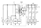
- FIG. 1 is a circuit diagram showing a connection relationship between the backup loads 61, 62, 63,.
- the in-vehicle power supply device 100A includes a main battery 1, a sub battery 2, and a power supply box 30A. Similar to the in-vehicle power supply devices 100C and 100D, the in-vehicle power supply device 100A preferably further includes a fuse connected in series with the auxiliary battery 2 with the power supply box 3 interposed therebetween. Here, the case where the said fuse is accommodated in the fuse box 4 similarly to the 1st comparative example and the 2nd comparative example is illustrated.
- the main battery 1 is charged by the power generation function of the alternator 9 from the outside of the in-vehicle power supply device 100A.
- a starter 8 is connected to the main battery 1 together with the general load 5 from the outside of the in-vehicle power supply device 100A.
- the general load 5 receives power via the main power supply path L1 as in the first comparative example and the second comparative example.
- the in-vehicle power supply device 100A in the present embodiment has a configuration in which the power supply box 30D of the in-vehicle power supply device 100D in the second comparative example is replaced with a power supply box 30A.
- the power supply box 30A includes the switch 31 described in the first comparative example and the second comparative example.
- the switch 31 is sandwiched between the secondary battery 2 and the fuse in the fuse box 4 and is connected in series.
- the sub battery 2 is connected to the main battery 1 via the switch 31. In other words, the switch 31 is connected between the main battery 1 and the sub battery 2.
- the switch 31 has an end 31 b on the side of the sub battery 2 and an end 31 a on the side opposite to the sub battery 2.
- the sub battery 2 supplies power to the backup loads 61, 62, 63,... Via the sub power feeding paths L21, L22, L23,.
- the auxiliary power supply paths L21, L22, L23,... are provided with fuses 321, 322, 323,.
- FIG. 1 illustrates the case where the fuses 321, 322, 323,... Are housed in the power supply box 30A.
- the power supply box 30A includes a switch 31, fuses 321, 322, 323,... And a plurality of contact pairs provided for each backup load 61, 62, 63,.
- relays 361, 362, 363,... are provided as contact pairs.
- the relay 361 has a first contact 361c and a second contact 361b, and is a normally closed relay.
- the relay 362 has a first contact 362c and a second contact 362b
- the relay 363 has a first contact 363c and a second contact 363b, respectively, and the relays 362, 363,. It is a relay.
- the second contacts 361b, 362b, 363b are connected to the sub battery 2 in common.
- the second contacts 361b, 362b, 363b are connected to the end 31b of the switch 31 on the sub battery 2 side.
- All the first contacts 361c, 362c, 363c,... are at least on the opposite side (here, the sub battery 2) of the switch 31 in a state where the contact pairs (here, relays 361, 362, 363,...) Are open. It is connected to the end 31a of the fuse box 4 side.
- the first contacts 361c, 362c, 363c are always connected to the end 31a.
- the first contacts 361c, 362c, 363c are also connected to the auxiliary power supply paths L21, L22, L23,... Via the fuses 321, 322, 323,.
- the relays 361, 362, 363,... are normally set in a non-conductive state (open) by a control device (not shown), for example, an in-vehicle ECU (engine control unit). Therefore, if the switch 31 becomes non-conductive, normally from the main battery 1 via the auxiliary power supply paths L21, L22, L23,... From the first contacts 361c, 362c, 363c to the backup loads 61, 62, 63,. Power is supplied.
- the first contacts 361c, 362c, 363c are not connected to the sub battery 2, and the sub battery 2 is disconnected from the main battery 1 by the relays 361, 362, 363,.
- current circulation is avoided while securing power supply to the outside (here, backup loads 61, 62, 63,).
- the switch 31 and the relays 361, 362, 363,... are connected in parallel, when the switch 31 is conductive, the relays 361, 362, 363,. It does not matter which state is closed. Therefore, when the switch 31 is conducting, the control device may leave the relays 361, 362, 363,... In a closed state due to circumstances not considered here. In this case, the relays 361, 362, 363,... Are opened at the same time as the switch 31 is turned off or after a predetermined time has elapsed. This predetermined time can be set to a time at which the inter-battery recirculation does not actually cause a problem, for example, the inter-battery recirculation is small in potential difference between the main battery 1 and the sub battery 2.
- the control device sets the relays 361, 362, 363,.
- the control device may not be able to set the relays 361, 362, 363,... Because both the alternator 9 and the main battery 1 have lost their power supply functions.
- the relays 361, 362, 363,... are normally closed, the relays 361, 362, 363,.
- the first contacts 361c, 362c, 363c, ... are connected to the second contacts 361b, 362b, 363b, ..., respectively, so that the auxiliary power supply path from the secondary battery 2 to the backup loads 61, 62, 63, ... Power is supplied via L21, L22, L23,.
- the power supply branches L11, L12, L13,... are not provided as in the second comparative example, so that the wiring is simplified and the fuses 71, 72, 73,. Specifically, the number of fuses is reduced by the number of backup loads as compared to the second comparative example.
- the relays 361, 362, 363 may be provided as individual relays, or the contact pairs may be realized by a plurality of relays.
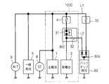
- FIG. 2 is a circuit diagram showing the connection relationship between the backup loads 61, 62, 63,.
- the in-vehicle power supply device 100B has a configuration in which the power supply box 30A is replaced with the power supply box 30B in the in-vehicle power supply device 100A described in the first embodiment.
- the power supply box 30 ⁇ / b> B includes a switch 31, a relay 35, and a fuse 32.
- the relay 35 has a first contact 35c, a second contact 35b, and a third contact 35a.
- a second contact 35b and a third contact 35a are complementarily connected to the first contact 35c.
- the third contact 35 a is connected to one end of the switch 31, here the end 31 a closer to the main battery 1 than the sub battery 2.
- the second contact 35 b is connected to the other end of the switch 31, here the end 31 b closer to the sub battery 2 than the main battery 1.
- the auxiliary power supply path L20 is drawn out from the in-vehicle power supply device 100B. Specifically, the auxiliary power supply path L20 is connected to the first contact 35c. A fuse 32 is provided in the auxiliary power feeding path L20.
- the auxiliary power supply path L20 branches to the power supply branches L201, L202, L203,... On the side opposite to the relay 35 with respect to the fuse 32, and serves as power supply paths to the backup loads 61, 62, 63,.
- Fuses 71, 72, 73,... Corresponding to the power supply branches L201, L202, L203,.
- the fuses 71, 72, 73,... are illustrated as being housed in the fuse box 70.
- the relays 361, 362, 363,... In the first embodiment are replaced with the relay 35, and the fuses 321, 322, 323,.
- the switch 31 When the charging rate of the secondary battery 2 falls within the proper range, the switch 31 becomes non-conductive and charging to the secondary battery 2 is stopped. Since the relay 35 complementarily connects the first contact 35c to either the second contact 35b or the third contact 35a, the relay 35 does not prevent the situation where the switch 31 is non-conductive. Therefore, when power is supplied to the outside of the in-vehicle power supply device 100 (here, the backup loads 61, 62, 63,...) Via the relay 35 (or further via the fuse 32), inter-battery recirculation is avoided.
- the first contact 35c is normally in a non-conductive state with the second contact 35b and is set in a conductive state with the third contact 35a.
- a control device for example, an in-vehicle ECU.
- the switch 31 becomes non-conductive, power is usually supplied from the main battery 1 via the power supply branches L201, L202, L203,... From the first contact point 35c to the backup loads 61, 62, 63,.
- the control device sets the first contact 35c to the second contact 35b and the third contact 35a to the non-conducting state in the relay 35 for reasons not considered here. May be.
- power is supplied from the secondary battery 2 to the backup loads 61, 62, 63,... Via the power supply branches L201, L202, L203,.
- the relay 35 connects the first contact 35c to the second contact 35b, so that the secondary battery 2 passes through the first contact 35c.
- the relay 35 connects the first contact 35c to the second contact 35b, so that the secondary battery 2 passes through the first contact 35c.
- the control device may not be able to set the relay 35 because both the alternator 9 and the main battery 1 have lost their power supply function.
- the third contact 35a of the relay 35 is a make contact and the second contact 35b is a break contact (in other words, if the first contact 35c and the second contact 35b are normally closed)
- the first contact 35c is electrically connected to the second contact 35b. Therefore, power is supplied from the secondary battery 2 to the backup loads 61, 62, 63,... Via the power supply branches L201, L202, L203,.
- the backup loads 61, 62, 63,... are replaced with the diode groups 60d, 61d, 62d, 63d,... As in the first comparative example and the backup loads 60, 61, 62, 63,. There is no need to provide a new design process.
- the number of contact pairs is further reduced by a value obtained by subtracting 1 from the number of backup loads, as compared with the first embodiment. That is, even if the number of backup loads is large, it is not necessary to provide many contact pairs, and the number of parts is reduced. This is more advantageous than the first embodiment from the viewpoint of reducing the size of the employed relay.
- the fuse 32 since the functions of the fuses 321, 322, and 323 in the first embodiment are substantially provided by the functions of the fuses 71, 72, and 73, the fuse 32 can be omitted in the present embodiment. In some cases, the number of parts is further reduced.
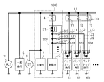
- FIG. 3 is a circuit diagram showing such a modification.
- the fuse 32 is connected not only to the first contact 35c but also to the end 31a.
- the first contact 35c and the second contact 35b are normally closed (the second contact 35b is a break contact).
- the relay 35 is controlled in the same manner as the relays 361, 362, 363,... Of the first embodiment, inter-battery recirculation can be avoided as in the first embodiment.
- a new design process for the diode groups 61d, 62d, and 63d is unnecessary.
- the number of contact pairs is reduced by a value obtained by subtracting 1 from the number of backup loads.
Landscapes
- Engineering & Computer Science (AREA)
- Mechanical Engineering (AREA)
- Power Engineering (AREA)
- Charge And Discharge Circuits For Batteries Or The Like (AREA)
- Control Of Charge By Means Of Generators (AREA)
- Direct Current Feeding And Distribution (AREA)
Priority Applications (2)
| Application Number | Priority Date | Filing Date | Title |
|---|---|---|---|
| US15/762,149 US20180290607A1 (en) | 2015-09-24 | 2016-09-12 | In-vehicle power supply device |
| CN201680054013.4A CN108025689B (zh) | 2015-09-24 | 2016-09-12 | 车载用电源装置 |
Applications Claiming Priority (2)
| Application Number | Priority Date | Filing Date | Title |
|---|---|---|---|
| JP2015186460A JP6569123B2 (ja) | 2015-09-24 | 2015-09-24 | 車載用電源装置 |
| JP2015-186460 | 2015-09-24 |
Publications (1)
| Publication Number | Publication Date |
|---|---|
| WO2017051737A1 true WO2017051737A1 (ja) | 2017-03-30 |
Family
ID=58386581
Family Applications (1)
| Application Number | Title | Priority Date | Filing Date |
|---|---|---|---|
| PCT/JP2016/076756 Ceased WO2017051737A1 (ja) | 2015-09-24 | 2016-09-12 | 車載用電源装置 |
Country Status (4)
| Country | Link |
|---|---|
| US (1) | US20180290607A1 (enExample) |
| JP (1) | JP6569123B2 (enExample) |
| CN (1) | CN108025689B (enExample) |
| WO (1) | WO2017051737A1 (enExample) |
Families Citing this family (5)
| Publication number | Priority date | Publication date | Assignee | Title |
|---|---|---|---|---|
| JP2017121864A (ja) * | 2016-01-07 | 2017-07-13 | 株式会社オートネットワーク技術研究所 | 給電中継回路、副電池モジュール、電源システム |
| JP6540565B2 (ja) * | 2016-03-16 | 2019-07-10 | 株式会社オートネットワーク技術研究所 | 車両用電源供給システム、車両用駆動システム |
| JP7287017B2 (ja) | 2019-03-14 | 2023-06-06 | 株式会社デンソー | 移動体用電源システム |
| JP7437226B2 (ja) * | 2020-05-01 | 2024-02-22 | 株式会社Subaru | 車両 |
| SE546924C2 (en) * | 2023-03-06 | 2025-03-11 | Blixt Tech Ab | Electrical coupling system |
Citations (3)
| Publication number | Priority date | Publication date | Assignee | Title |
|---|---|---|---|---|
| JP2002064946A (ja) * | 2000-08-11 | 2002-02-28 | Sony Corp | 電源装置 |
| JP2006033906A (ja) * | 2004-07-12 | 2006-02-02 | Denso Corp | 車両用電源回路 |
| JP2015046964A (ja) * | 2013-08-27 | 2015-03-12 | 本田技研工業株式会社 | 車両診断装置の電源バックアップ回路 |
Family Cites Families (6)
| Publication number | Priority date | Publication date | Assignee | Title |
|---|---|---|---|---|
| JP5299944B2 (ja) * | 2008-01-23 | 2013-09-25 | 本田技研工業株式会社 | 燃料電池電源装置 |
| JP4573884B2 (ja) * | 2008-06-18 | 2010-11-04 | 三菱電機株式会社 | 車載電子制御装置の電源異常検出回路 |
| JP5930041B2 (ja) * | 2012-07-27 | 2016-06-08 | 日産自動車株式会社 | 車両の制御装置および車両の制御方法 |
| CN105144325B (zh) * | 2012-09-20 | 2021-01-12 | 安波福技术有限公司 | 继电器组件 |
| WO2015174379A1 (ja) * | 2014-05-12 | 2015-11-19 | 株式会社オートネットワーク技術研究所 | 自動車の電源装置 |
| CN204586527U (zh) * | 2015-05-14 | 2015-08-26 | 成都运达科技股份有限公司 | 列车辅助电源系统 |
-
2015
- 2015-09-24 JP JP2015186460A patent/JP6569123B2/ja not_active Expired - Fee Related
-
2016
- 2016-09-12 CN CN201680054013.4A patent/CN108025689B/zh not_active Expired - Fee Related
- 2016-09-12 WO PCT/JP2016/076756 patent/WO2017051737A1/ja not_active Ceased
- 2016-09-12 US US15/762,149 patent/US20180290607A1/en not_active Abandoned
Patent Citations (3)
| Publication number | Priority date | Publication date | Assignee | Title |
|---|---|---|---|---|
| JP2002064946A (ja) * | 2000-08-11 | 2002-02-28 | Sony Corp | 電源装置 |
| JP2006033906A (ja) * | 2004-07-12 | 2006-02-02 | Denso Corp | 車両用電源回路 |
| JP2015046964A (ja) * | 2013-08-27 | 2015-03-12 | 本田技研工業株式会社 | 車両診断装置の電源バックアップ回路 |
Also Published As
| Publication number | Publication date |
|---|---|
| CN108025689A (zh) | 2018-05-11 |
| CN108025689B (zh) | 2021-03-09 |
| JP6569123B2 (ja) | 2019-09-04 |
| US20180290607A1 (en) | 2018-10-11 |
| JP2017061179A (ja) | 2017-03-30 |
Similar Documents
| Publication | Publication Date | Title |
|---|---|---|
| WO2017051736A1 (ja) | 車載用電源装置 | |
| US10549705B2 (en) | Switch device for on-board power supply and on-board power supply device | |
| US10676053B2 (en) | Power source device | |
| CN106255622B (zh) | 用于将基础车载电网与尤其与安全相关的分网连接的装置 | |
| US10668877B2 (en) | Switch device for on-board power supply and on-board power supply system | |
| JP6569123B2 (ja) | 車載用電源装置 | |
| US10916962B2 (en) | Dual energy store and dual charging source vehicle power supply system and vehicle drive system | |
| WO2017051741A1 (ja) | 車載用電源装置 | |
| WO2017051812A1 (ja) | 車載用電源装置及びその制御方法 | |
| US20220348156A1 (en) | Vehicle electrical system and power module therefor | |
| JP2016187235A (ja) | バッテリシステム制御装置 | |
| CN108973903B (zh) | 一种车载供电系统及车辆 | |
| JP6379866B2 (ja) | 電源装置 | |
| JP2017052473A (ja) | 車載用電源装置 | |
| CN112714711B (zh) | 提供冗余电力的系统和方法 | |
| US20250135951A1 (en) | On-board electrical system for a motor vehicle and method for operating an on-board electrical system for a motor vehicle | |
| JP2015221595A (ja) | 自動車の電源装置 | |
| US12107418B2 (en) | System for the electric power supply of a vehicle | |
| US12179613B2 (en) | Vehicle, method, device and steering system for a vehicle |
Legal Events
| Date | Code | Title | Description |
|---|---|---|---|
| 121 | Ep: the epo has been informed by wipo that ep was designated in this application |
Ref document number: 16848525 Country of ref document: EP Kind code of ref document: A1 |
|
| WWE | Wipo information: entry into national phase |
Ref document number: 15762149 Country of ref document: US |
|
| NENP | Non-entry into the national phase |
Ref country code: DE |
|
| 122 | Ep: pct application non-entry in european phase |
Ref document number: 16848525 Country of ref document: EP Kind code of ref document: A1 |