WO2017047748A1 - ガスバリアフィルム及び断熱パネル - Google Patents
ガスバリアフィルム及び断熱パネル Download PDFInfo
- Publication number
- WO2017047748A1 WO2017047748A1 PCT/JP2016/077446 JP2016077446W WO2017047748A1 WO 2017047748 A1 WO2017047748 A1 WO 2017047748A1 JP 2016077446 W JP2016077446 W JP 2016077446W WO 2017047748 A1 WO2017047748 A1 WO 2017047748A1
- Authority
- WO
- WIPO (PCT)
- Prior art keywords
- gas barrier
- vapor deposition
- deposition layer
- barrier film
- film
- Prior art date
- Legal status (The legal status is an assumption and is not a legal conclusion. Google has not performed a legal analysis and makes no representation as to the accuracy of the status listed.)
- Ceased
Links
Images
Classifications
-
- B—PERFORMING OPERATIONS; TRANSPORTING
- B32—LAYERED PRODUCTS
- B32B—LAYERED PRODUCTS, i.e. PRODUCTS BUILT-UP OF STRATA OF FLAT OR NON-FLAT, e.g. CELLULAR OR HONEYCOMB, FORM
- B32B9/00—Layered products comprising a layer of a particular substance not covered by groups B32B11/00 - B32B29/00
-
- B—PERFORMING OPERATIONS; TRANSPORTING
- B32—LAYERED PRODUCTS
- B32B—LAYERED PRODUCTS, i.e. PRODUCTS BUILT-UP OF STRATA OF FLAT OR NON-FLAT, e.g. CELLULAR OR HONEYCOMB, FORM
- B32B15/00—Layered products comprising a layer of metal
- B32B15/04—Layered products comprising a layer of metal comprising metal as the main or only constituent of a layer, which is next to another layer of the same or of a different material
- B32B15/08—Layered products comprising a layer of metal comprising metal as the main or only constituent of a layer, which is next to another layer of the same or of a different material of synthetic resin
-
- B—PERFORMING OPERATIONS; TRANSPORTING
- B65—CONVEYING; PACKING; STORING; HANDLING THIN OR FILAMENTARY MATERIAL
- B65D—CONTAINERS FOR STORAGE OR TRANSPORT OF ARTICLES OR MATERIALS, e.g. BAGS, BARRELS, BOTTLES, BOXES, CANS, CARTONS, CRATES, DRUMS, JARS, TANKS, HOPPERS, FORWARDING CONTAINERS; ACCESSORIES, CLOSURES, OR FITTINGS THEREFOR; PACKAGING ELEMENTS; PACKAGES
- B65D65/00—Wrappers or flexible covers; Packaging materials of special type or form
- B65D65/38—Packaging materials of special type or form
- B65D65/40—Applications of laminates for particular packaging purposes
-
- B—PERFORMING OPERATIONS; TRANSPORTING
- B65—CONVEYING; PACKING; STORING; HANDLING THIN OR FILAMENTARY MATERIAL
- B65D—CONTAINERS FOR STORAGE OR TRANSPORT OF ARTICLES OR MATERIALS, e.g. BAGS, BARRELS, BOTTLES, BOXES, CANS, CARTONS, CRATES, DRUMS, JARS, TANKS, HOPPERS, FORWARDING CONTAINERS; ACCESSORIES, CLOSURES, OR FITTINGS THEREFOR; PACKAGING ELEMENTS; PACKAGES
- B65D81/00—Containers, packaging elements, or packages, for contents presenting particular transport or storage problems, or adapted to be used for non-packaging purposes after removal of contents
- B65D81/18—Containers, packaging elements, or packages, for contents presenting particular transport or storage problems, or adapted to be used for non-packaging purposes after removal of contents providing specific environment for contents, e.g. temperature above or below ambient
- B65D81/20—Containers, packaging elements, or packages, for contents presenting particular transport or storage problems, or adapted to be used for non-packaging purposes after removal of contents providing specific environment for contents, e.g. temperature above or below ambient under vacuum or superatmospheric pressure, or in a special atmosphere, e.g. of inert gas
-
- B—PERFORMING OPERATIONS; TRANSPORTING
- B65—CONVEYING; PACKING; STORING; HANDLING THIN OR FILAMENTARY MATERIAL
- B65D—CONTAINERS FOR STORAGE OR TRANSPORT OF ARTICLES OR MATERIALS, e.g. BAGS, BARRELS, BOTTLES, BOXES, CANS, CARTONS, CRATES, DRUMS, JARS, TANKS, HOPPERS, FORWARDING CONTAINERS; ACCESSORIES, CLOSURES, OR FITTINGS THEREFOR; PACKAGING ELEMENTS; PACKAGES
- B65D81/00—Containers, packaging elements, or packages, for contents presenting particular transport or storage problems, or adapted to be used for non-packaging purposes after removal of contents
- B65D81/24—Adaptations for preventing deterioration or decay of contents; Applications to the container or packaging material of food preservatives, fungicides, pesticides or animal repellants
-
- B—PERFORMING OPERATIONS; TRANSPORTING
- B65—CONVEYING; PACKING; STORING; HANDLING THIN OR FILAMENTARY MATERIAL
- B65D—CONTAINERS FOR STORAGE OR TRANSPORT OF ARTICLES OR MATERIALS, e.g. BAGS, BARRELS, BOTTLES, BOXES, CANS, CARTONS, CRATES, DRUMS, JARS, TANKS, HOPPERS, FORWARDING CONTAINERS; ACCESSORIES, CLOSURES, OR FITTINGS THEREFOR; PACKAGING ELEMENTS; PACKAGES
- B65D81/00—Containers, packaging elements, or packages, for contents presenting particular transport or storage problems, or adapted to be used for non-packaging purposes after removal of contents
- B65D81/38—Containers, packaging elements, or packages, for contents presenting particular transport or storage problems, or adapted to be used for non-packaging purposes after removal of contents with thermal insulation
-
- C—CHEMISTRY; METALLURGY
- C23—COATING METALLIC MATERIAL; COATING MATERIAL WITH METALLIC MATERIAL; CHEMICAL SURFACE TREATMENT; DIFFUSION TREATMENT OF METALLIC MATERIAL; COATING BY VACUUM EVAPORATION, BY SPUTTERING, BY ION IMPLANTATION OR BY CHEMICAL VAPOUR DEPOSITION, IN GENERAL; INHIBITING CORROSION OF METALLIC MATERIAL OR INCRUSTATION IN GENERAL
- C23C—COATING METALLIC MATERIAL; COATING MATERIAL WITH METALLIC MATERIAL; SURFACE TREATMENT OF METALLIC MATERIAL BY DIFFUSION INTO THE SURFACE, BY CHEMICAL CONVERSION OR SUBSTITUTION; COATING BY VACUUM EVAPORATION, BY SPUTTERING, BY ION IMPLANTATION OR BY CHEMICAL VAPOUR DEPOSITION, IN GENERAL
- C23C14/00—Coating by vacuum evaporation, by sputtering or by ion implantation of the coating forming material
- C23C14/06—Coating by vacuum evaporation, by sputtering or by ion implantation of the coating forming material characterised by the coating material
-
- C—CHEMISTRY; METALLURGY
- C23—COATING METALLIC MATERIAL; COATING MATERIAL WITH METALLIC MATERIAL; CHEMICAL SURFACE TREATMENT; DIFFUSION TREATMENT OF METALLIC MATERIAL; COATING BY VACUUM EVAPORATION, BY SPUTTERING, BY ION IMPLANTATION OR BY CHEMICAL VAPOUR DEPOSITION, IN GENERAL; INHIBITING CORROSION OF METALLIC MATERIAL OR INCRUSTATION IN GENERAL
- C23C—COATING METALLIC MATERIAL; COATING MATERIAL WITH METALLIC MATERIAL; SURFACE TREATMENT OF METALLIC MATERIAL BY DIFFUSION INTO THE SURFACE, BY CHEMICAL CONVERSION OR SUBSTITUTION; COATING BY VACUUM EVAPORATION, BY SPUTTERING, BY ION IMPLANTATION OR BY CHEMICAL VAPOUR DEPOSITION, IN GENERAL
- C23C14/00—Coating by vacuum evaporation, by sputtering or by ion implantation of the coating forming material
- C23C14/06—Coating by vacuum evaporation, by sputtering or by ion implantation of the coating forming material characterised by the coating material
- C23C14/08—Oxides
-
- F—MECHANICAL ENGINEERING; LIGHTING; HEATING; WEAPONS; BLASTING
- F16—ENGINEERING ELEMENTS AND UNITS; GENERAL MEASURES FOR PRODUCING AND MAINTAINING EFFECTIVE FUNCTIONING OF MACHINES OR INSTALLATIONS; THERMAL INSULATION IN GENERAL
- F16L—PIPES; JOINTS OR FITTINGS FOR PIPES; SUPPORTS FOR PIPES, CABLES OR PROTECTIVE TUBING; MEANS FOR THERMAL INSULATION IN GENERAL
- F16L59/00—Thermal insulation in general
- F16L59/06—Arrangements using an air layer or vacuum
- F16L59/065—Arrangements using an air layer or vacuum using vacuum
-
- Y—GENERAL TAGGING OF NEW TECHNOLOGICAL DEVELOPMENTS; GENERAL TAGGING OF CROSS-SECTIONAL TECHNOLOGIES SPANNING OVER SEVERAL SECTIONS OF THE IPC; TECHNICAL SUBJECTS COVERED BY FORMER USPC CROSS-REFERENCE ART COLLECTIONS [XRACs] AND DIGESTS
- Y02—TECHNOLOGIES OR APPLICATIONS FOR MITIGATION OR ADAPTATION AGAINST CLIMATE CHANGE
- Y02W—CLIMATE CHANGE MITIGATION TECHNOLOGIES RELATED TO WASTEWATER TREATMENT OR WASTE MANAGEMENT
- Y02W90/00—Enabling technologies or technologies with a potential or indirect contribution to greenhouse gas [GHG] emissions mitigation
- Y02W90/10—Bio-packaging, e.g. packing containers made from renewable resources or bio-plastics
Definitions
- the present invention is a highly practical heat insulating material that exhibits an excellent heat insulating effect when attached to a vacuum package of various products such as processed agricultural products, processed fishery products, prepared dishes, seasonings, pet food, refrigerators, low temperature containers, etc.
- the present invention relates to a gas barrier film suitable for a panel exterior material.
- an aluminum foil and an aluminum vapor deposition film As a material having excellent gas barrier properties, an aluminum foil and an aluminum vapor deposition film have generally been employed. Gas barrier properties can be satisfied by using an aluminum foil and an aluminum vapor-deposited film as a barrier material. Furthermore, in order to give piercing strength to the barrier material, the use of a polyamide film and a polyester film with excellent mechanical strength on the outside of the barrier material has prevented the occurrence of pinholes in the barrier material. .
- a transparent gas barrier film in which alumina or silica is deposited is known as a gas barrier film (see, for example, Patent Document 1).
- a gas barrier film in vacuum packaging, the transparent gas barrier film is in close contact with the contents, and thus deforms along the outer shape of the contents. For this reason, the transparent gas barrier film is partially bent or stretched according to the outer shape of the contents. This bending or stretching may cause cracks in the deposited layer that is aluminum oxide, which is ceramic. And when a crack generate
- the present invention has been made in view of the above circumstances, and an object thereof is to provide a gas barrier film having excellent heat insulation performance and capable of retaining heat insulation performance even when applied to vacuum packaging.
- the gas barrier film according to the first aspect of the present invention comprises a transparent plastic film substrate, a ceramic vapor deposition layer formed of AlO x sequentially provided on the first surface of the transparent plastic film substrate, and a metal vapor deposition layer.
- Said 1st aspect WHEREIN The thickness of the said metal vapor deposition layer may exist in the range of 5 nm or more and 30 nm or less.
- the transparent plastic film substrate may have a functional group on the first surface, and the ceramic vapor deposition layer may be provided on the first surface.
- any one compound selected from a metal alkoxide, a hydrolyzate thereof, and a polymer thereof, and a hydroxyl group-containing polymer compound may be provided.
- the hydroxyl group-containing polymer compound may contain at least one of polyvinyl alcohol, polyvinyl pyrrolidone, cellulose, and starch.
- the transparent plastic film substrate is at least one of polyethylene, polypropylene, polyamides, polyesters, polycarbonate, polyacrylonitrile, polystyrene, polyvinyl chloride, cellulose, triacetyl cellulose, polyvinyl alcohol, and polyurethane. Or one of them.
- the heat insulation panel according to the second aspect of the present invention includes the gas barrier film according to the first aspect and the contents vacuum-packed by the gas barrier film.
- the gas barrier film which concerns on the said aspect has a thin metal vapor deposition layer, it can reduce the heat conduction through a metal vapor deposition layer. Since the gas barrier film according to the above aspect has a thin metal vapor deposition layer, the gas barrier property is inferior depending on the thinness. However, since the ceramic vapor deposition layer is provided in addition to the metal vapor deposition layer, both vapor deposition layers are excellent as a whole. Demonstrates gas barrier properties. Since the ceramic vapor deposition layer is formed of AlO x (x is in the range of 1.5 to 1.7), the thermal conductivity is small, and the amount of heat flowing through the ceramic vapor deposition layer is small.
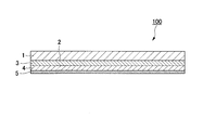
- FIG. 1 is a schematic cross-sectional view of a gas barrier film according to an embodiment of the present invention.
- the gas barrier film 100 of the present embodiment includes a transparent plastic film substrate 1, a ceramic deposition layer 3 disposed in order on the plasma pretreatment layer 2 of the transparent plastic film substrate 1, and a gas barrier.
- the conductive coating layer 4 and the metal vapor deposition layer 5 are provided.
- the plasma pretreatment layer 2 is formed by subjecting at least one surface (first surface) of the transparent plastic film substrate 1 to pretreatment by reactive ion etching using plasma.
- a substrate having a total light transmittance of 85% or more is desirable.
- a polyethylene terephthalate film, a polyethylene naphthalate film, or the like can be used as a substrate having high transparency and excellent heat resistance.
- polyethylene, polypropylene, polyamides, polyesters, polycarbonate, polyacrylonitrile, polystyrene, polyvinyl chloride, cellulose, triacetyl cellulose, polyvinyl alcohol, or polyurethane films may be used.
- a polyethylene terephthalate film is preferable.
- the thickness of the transparent plastic film substrate 1 is not particularly limited, but is desirably 50 ⁇ m or less in order to reduce the total thickness of the transparent gas barrier film 100.
- the thickness of the transparent plastic film substrate 1 is preferably 12 ⁇ m or more in order to form the ceramic vapor deposition layer 3, the gas barrier coating layer 4 and the metal vapor deposition layer 5 and obtain excellent gas barrier properties. That is, the thickness of the transparent plastic film substrate 1 is preferably in the range of 12 ⁇ m to 50 ⁇ m.
- the surface of the transparent plastic film substrate 1 is subjected to reactive ion etching (RIE) using plasma in order to strengthen the adhesion between the transparent plastic film substrate 1 and the ceramic vapor deposition layer 3.
- RIE reactive ion etching
- Pretreatment is performed, and a plasma pretreatment layer 2 is formed.
- the chemical effect of making the surface of the transparent plastic film substrate 1 have a functional group using the generated radicals and ions, and the surface is ion-etched to remove impurities, etc.
- Two effects such as a physical effect of smoothing the surface, can be obtained simultaneously.
- By forming such a plasma pretreatment layer 2 it is possible to densely form the ceramic vapor deposition layer 3 thereon.
- the processing conditions indicated by the processing speed and energy level when performing the RIE processing should be set as appropriate.
- plasma pretreatment using RIE it is possible to chemically change the surface structure of the PET film using the generated radicals and ions, and to control the half-width of the CC bond. it can.
- the base material is a polyethylene terephthalate film
- the half-value width of the CC bond in the polyethylene terephthalate structure in the waveform separation of C1s is in the range of 1.340 to 1.560 eV. It is preferable to use such a polyethylene terephthalate film.
- the adhesiveness is inferior like untreated polyethylene terephthalate, and delamination may occur during long-term storage.
- the half width is 1.560 eV or more, the surface of the polyethylene terephthalate deteriorates and the adhesion becomes weak.
- the ceramic vapor-deposited layer 3 needs to be a vapor-deposited layer formed from aluminum oxide in which x of aluminum oxide represented by the general formula AlO x is in the range of 1.5 to 1.7.
- the value of x can be measured by X-ray photoelectron spectroscopy measurement (XPS measurement) on the aluminum oxide vapor deposition layer surface. That is, the aluminum oxide vapor-deposited layer is scraped from the surface to a depth of about two thirds of the thickness by Ar ion etching, and the exposed surface portion is subjected to XPS measurement under conditions of an X-ray source MgK ⁇ and an X-ray output of 100 W. The value of x is obtained from the ratio of the obtained aluminum atom and oxygen atom.
- XPS measurement X-ray photoelectron spectroscopy measurement
- the element ratio changes due to the effects of oxidation and surface contamination by oxygen in the air, and if it is etched too much, the influence of the substrate will come out, so it is not possible to obtain the correct value . Therefore, as described above, it is necessary to perform measurement after scraping the aluminum oxide vapor-deposited layer to a depth of about two-thirds from its surface.
- the value of x of AlO x obtained by such measurement is 1.5 or less, there is a large amount of aluminum, so the aluminum oxide vapor deposition layer is colored and the appearance is impaired. Furthermore, when the aluminum is in an excessive state, the interaction between the functional group on the surface of the substrate and the aluminum oxide is unlikely to occur, so that the adhesion with the substrate is deteriorated, which is not preferable. Further, when the value of x of AlO x is 1.7 or more, oxygen is in an excessive state. Since the aluminum oxide vapor deposition layer in such a state is hard and brittle, it is weak against elongation and easily cracks, resulting in a possibility of a decrease in barrier properties.
- the thickness (film thickness) of the ceramic vapor deposition layer 3 is preferably in the range of 5 nm to 500 nm, and more preferably in the range of 5 nm to 100 nm.
- the film thickness is 5 nm or more, it is easy to form a uniform film, and the function as a gas barrier material tends to be more sufficiently achieved.
- the film thickness is 500 nm or less, sufficient flexibility can be maintained by the thin film, and it is possible to more reliably prevent the thin film from cracking due to external factors such as bending and pulling after the film formation. There is a tendency to be able to.
- a normal vacuum vapor deposition method can be used as a method of forming a vapor deposition layer formed of an inorganic oxide on the transparent plastic film substrate as the ceramic vapor deposition layer 3.
- other thin film forming methods such as sputtering, ion plating, and plasma vapor deposition (CVD) can also be used. If productivity is considered, the vacuum evaporation method can be used preferably.
- a heating means of the vacuum deposition method any of an electron beam heating method, a resistance heating method, and an induction heating method is preferable.
- vapor-deposit in order to improve the adhesiveness of a vapor deposition layer and a base material, and the denseness of a vapor deposition layer, it is also possible to vapor-deposit using a plasma assist method or an ion beam assist method.
- reactive vapor deposition in which oxygen gas or the like is blown can be performed.
- the gas barrier coating layer 4 is provided to prevent various secondary damages in a later process and to impart high barrier properties.
- the gas barrier coating layer 4 contains at least one compound selected from a metal alkoxide, a hydrolyzate thereof, and a polymer thereof and a hydroxyl group-containing polymer compound as components from the viewpoint of obtaining excellent barrier properties. It is preferable.
- the metal alkoxide is represented by the general formula: M (OR) n (M represents a metal atom such as Si, Ti, Al, Zr, R represents an alkyl group such as —CH 3 , —C 2 H 5 , and n represents M Represents an integer corresponding to the valence of.
- M represents a metal atom such as Si, Ti, Al, Zr
- R represents an alkyl group such as —CH 3 , —C 2 H 5
- n represents M Represents an integer corresponding to the valence of.
- Specific examples include tetraethoxysilane [Si (OC 2 H 5 ) 4 ], triisopropoxyaluminum [Al (O-iso-C 3 H 7 ) 3 ] and the like. Tetraethoxysilane and triisopropoxyaluminum are preferable because they are relatively stable in an aqueous solvent after hydrolysis.
- hydrolyzate and polymer of metal alkoxide examples include silicic acid (Si (OH) 4 ) as the hydrolyzate and polymer of tetraethoxysilane, and the hydrolyzate and polymer of tripropoxyaluminum.
- the material examples include aluminum hydroxide (Al (OH) 3 ).
- hydroxyl group-containing polymer compound examples include water-soluble polymers such as polyvinyl alcohol, polyvinyl pyrrolidone, and starch.
- barrier properties are most excellent when polyvinyl alcohol is used.
- the thickness (film thickness) of the gas barrier coating layer 4 is preferably in the range of 50 nm to 1000 nm, and more preferably in the range of 100 nm to 500 nm.
- the film thickness is 50 nm or more, there is a tendency that sufficient gas barrier properties can be obtained, and when it is 1000 nm or less, there is a tendency that sufficient flexibility can be maintained by the thin film.
- Conventionally known means such as a dipping method, a roll coating method, a screen printing method, a spray method, and a gravure printing method can be used as a method for applying a coating agent containing a material for forming a gas barrier film layer.
- metal thin films such as aluminum and tin, or those mixtures can be used. Among these, it is desirable to use aluminum from the viewpoint of barrier properties and productivity.
- the thickness (film thickness) of the metal vapor-deposited layer 5 needs to be in the range of 5 nm to 60 nm.
- the film thickness is 5 nm or more, it is easy to form a uniform film, and the function as a gas barrier material tends to be more fully achieved.
- the film thickness is 60 nm or less, sufficient flexibility can be maintained by the thin film, and it is possible to more reliably prevent the thin film from cracking due to external factors such as bending and pulling after the film formation. it can.
- the thickness of the metal vapor-deposited layer 5 is particularly preferably 30 nm or less.
- a normal vacuum vapor deposition method can be used.
- other thin film forming methods such as sputtering, ion plating, and plasma vapor deposition (CVD) can also be used.
- the vacuum evaporation method can be used preferably.
- a heating means of the vacuum deposition method any of an electron beam heating method, a resistance heating method, and an induction heating method is preferable.
- a plasma assist method or an ion beam assist method it is also possible to vapor-deposit using a plasma assist method or an ion beam assist method.
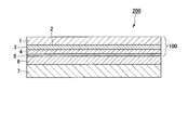
- a transparent gas barrier laminated film 200 is formed by laminating an adhesive layer 6 and a sealant film 7 on the metal vapor deposition layer 5 of the gas barrier film 100, and vacuum packaging is performed using the gas barrier laminated film 200. be able to.
- the adhesive layer 6 is provided to bond the metal deposition layer 5 formed on the gas barrier film 100 and the sealant film 7 together.
- Adhesives and adhesives such as an acryl-type material, a urethane type material, and a polyester-type material, can be used. More specifically, an acrylic pressure-sensitive adhesive, an acrylic adhesive, a urethane adhesive, or an ester adhesive can be used.
- the thickness of the adhesive layer 6 is not particularly limited, but is desirably 30 ⁇ m or less in order to reduce the total thickness of the gas barrier laminated film 200.
- the thickness of the adhesive layer 6 is desirably 2 ⁇ m or more. That is, the thickness of the adhesive layer 6 is preferably in the range of 2 ⁇ m to 30 ⁇ m.
- an adhesive can be applied to any surface to be bonded, and dried if necessary to form an adhesive layer.
- a reverse roll coater, knife coater, bar coater, slot die coater, air knife coater, reverse gravure coater, vario gravure coater or the like is used as an adhesive application device.
- the application amount of the pressure-sensitive adhesive is desirably in the range of 1 to 30 ⁇ m in thickness.
- the sealant film 7 is made of, for example, polyethylene, polypropylene, ethylene / vinyl acetate copolymer, ethylene / methacrylic acid copolymer, ethylene / methacrylic acid ester copolymer, ethylene / acrylic acid copolymer, ethylene / acrylic acid ester copolymer. Resins such as polymers and their cross-linked metal products can be used. From the viewpoint of processability and economy, polyethylene, polypropylene, and ethylene / vinyl acetate copolymer are desirable.
- the thickness of the sealant film 7 is determined according to the purpose, but is generally in the range of 15 to 200 ⁇ m.
- an extrusion lamination method or the like can be used without using the adhesive layer 6.
- An anchor coat layer (not shown) may be provided in order to further improve the adhesion.
- the anchor coat layer is not particularly limited, but an adhesive or pressure sensitive adhesive such as an acrylic material, a urethane material, or a polyester material can be used.
- a third plastic film may be provided between the gas barrier film 100 and the sealant film 7. Thereby, high puncture resistance and bending resistance are obtained.
- the third plastic film is not particularly limited, and a polyamide film, a stretched polypropylene film, and the like can be used.
- a fourth plastic film may be provided on the surface of the gas barrier film 100 opposite to the surface on which the sealant film 7 is laminated. Thereby, high puncture resistance and bending resistance are obtained.
- the fourth plastic film is not particularly limited, but a polyamide film, a stretched polypropylene film, or the like can be used. Both the third plastic film and the fourth plastic film may be provided, or only one of them may be provided. A plurality of plastic films may be laminated as the third plastic film and the fourth plastic film.
- Example 1 A polyethylene terephthalate film having a thickness of 12 ⁇ m is prepared as a transparent plastic film substrate. On one side (first surface), applied power is 120 W, processing time is 0.1 sec, processing gas is argon gas, and processing unit pressure is 2.0 Pa. As a plasma pretreatment using reactive ion etching (RIE). At this time, a high frequency power source having a frequency of 13.56 MHz was used for the electrodes.
- RIE reactive ion etching
- a coating liquid containing tetraethoxysilane and polyvinyl alcohol was applied onto the aluminum oxide vapor deposition layer by a wet coating method to form a gas barrier coating layer having a thickness of 0.3 ⁇ m.
- the gas barrier film of Example 1 was obtained by providing the aluminum vapor deposition layer formed from aluminum on the gas barrier coating layer in the thickness of 15 nm.
- Example 2 A gas barrier film of Example 2 was obtained in the same manner as in Example 1 except that the applied power was 250 W and the thickness of the aluminum oxide vapor deposition layer was 9 nm.
- Comparative Example 1 The gas barrier film of Comparative Example 1 was prepared in the same manner as in Example 1 except that the flow rate of oxygen was adjusted so that the aluminum oxide vapor-deposited layer was transparent and the thickness of the aluminum oxide vapor-deposited layer was 4 nm. Got.
- Comparative Example 2 A gas barrier film of Comparative Example 2 was obtained in the same manner as in Example 1 except that the flow rate of oxygen was adjusted so that the aluminum oxide vapor deposition layer was transparent and the thickness was 30 nm.
- Comparative Example 3 A gas barrier film of Comparative Example 3 was obtained in the same manner as in Example 1 except that an aluminum vapor deposition layer formed of aluminum was provided to a thickness of 100 nm on the gas barrier coating layer.
- Comparative Example 4 A gas barrier film of Comparative Example 4 was obtained in the same manner as in Example 1 except that an aluminum vapor deposition layer formed of aluminum was not provided on the gas barrier coating layer.
- a rigid polyurethane foam as a heat insulating core material was cut into a 200 ⁇ 200 ⁇ 30 mm thick plate and dried (120 ° C., 1 hour). Then, the rigid polyurethane foam was accommodated in the heat insulation core material accommodation bag. After degassing the interior space of the bag, the opening of the bag was sealed by heat sealing. The sealing pressure was 0.05 Torr. Using a press-pressing device, the containing material containing the rigid polyurethane foam, that is, the vacuum heat insulating material, was pressurized and compressed. The pressurizing pressure of the above apparatus was 70 ton (about 150 kgf / cm 2 ).
- the x value of AlO x of each sample was determined.
- the X-ray photoelectron spectrometer used for the measurement was JPS-90MXV manufactured by JEOL Ltd. Using this device, non-monochromated MgK ⁇ (1253.6 eV) was used as the X-ray source, and the output was 100 W (10 kV-10 mA). The measurement results are shown in Table 1.
- thermo conductivity measurement For the heat insulating panels produced in Examples 1 and 2 and Comparative Examples 1 to 4, the thermal conductivity of the obtained vacuum heat insulating material was measured by a plate heat flow meter method (AUTO- ⁇ HC-072) defined in JIS-A9511. It was measured. The measurement results are shown in Table 1.
- the gas barrier films of Examples 1 and 2 have good barrier properties by having a ceramic vapor deposition layer, a gas barrier coating layer, and a metal vapor deposition layer having an appropriate ratio of oxygen and aluminum. Is shown. Therefore, even when vacuum packaging is performed to form a heat insulating panel, the barrier property can be maintained, so that excellent heat insulating property can be maintained.
- the gas barrier film of Comparative Example 3 had excellent barrier properties because the metal deposition layer was very thick. On the other hand, since the aluminum vapor deposition layer thickness with high heat conductivity was thick, the heat conductivity in a heat insulation panel was high, and heat insulation was low.
- the gas barrier film of Comparative Example 4 does not have a metal vapor deposition layer, but has an excellent barrier property because the ceramic vapor deposition layer and the like are optimized. However, in a use application including elements such as bending and stretching, such as a heat insulating panel, the ceramic deposited layer is deteriorated. For this reason, in Comparative Example 4, even when the barrier property of the gas barrier film alone is good, the thermal conductivity of the heat insulating panel is increased and the heat insulating property is decreased because the ceramic vapor-deposited layer is deteriorated when the heat insulating panel is manufactured. It is done.
- the gas barrier film of the present invention can be used for applications such as vacuum packaging and heat insulation panels that are partially stretched and require high barrier properties.
Landscapes
- Engineering & Computer Science (AREA)
- Mechanical Engineering (AREA)
- Chemical & Material Sciences (AREA)
- Metallurgy (AREA)
- Chemical Kinetics & Catalysis (AREA)
- Materials Engineering (AREA)
- General Engineering & Computer Science (AREA)
- Organic Chemistry (AREA)
- Food Science & Technology (AREA)
- Laminated Bodies (AREA)
- Wrappers (AREA)
- Thermal Insulation (AREA)
- Physical Vapour Deposition (AREA)
Abstract
ガスバリアフィルムは、透明プラスチックフィルム基材と、前記透明プラスチックフィルム基材の第1面に順次設けられたAlOxから形成されるセラミック蒸着層と、金属蒸着層とを有するガスバリアフィルムであって、前記xが1.5以上1.7以下の範囲内であり、前記金属蒸着層の厚みが5nm以上60nm以下の範囲内である。
Description
本発明は、農産加工品、水産加工品、総菜、調味料、ペットフードなど様々な商品の真空包装体や、冷蔵庫、低温コンテナ等に取り付けて、優れた断熱効果を発揮する実用性の高い断熱パネル外装材に適した、ガスバリアフィルムに関する。
本願は、2015年9月17日に日本に出願された特願2015-183929号に基づき優先権を主張し、その内容をここに援用する。
本願は、2015年9月17日に日本に出願された特願2015-183929号に基づき優先権を主張し、その内容をここに援用する。
真空包装や断熱パネルの外装材には、内容物の鮮度や断熱性能を保持するため、内部を長期間真空状態で保持すると共に、外部からのガスの進入を防ぐため、ガスバリア性の優れた材料を使用している。
このガスバリア性の優れた材料として、一般的に、アルミニウム箔、およびアルミニウム蒸着フィルムが採用されてきた。アルミニウム箔、およびアルミニウム蒸着フィルムを、バリア材として用いることで、ガスバリア性を満足させることができる。さらに、バリア材に突き刺し強度を付与するために、バリア材の外側に機械的な強度が優れたポリアミドフィルム、ポリエステルフィルムを合わせて使用することにより、バリア材のピンホール等の発生を防止してきた。
しかしながら、アルミニウム箔は熱伝導率が高いため、アルミニウム箔の断面を通じて熱が伝わる。このため、アルミニウム箔を使用した場合には断熱性能に限界がある。また、アルミニウム蒸着フィルムは、蒸着層がアルミニウム箔に比較して薄いため、比較的高い断熱性を発揮するが、やはり、断熱性能には限界がある。なお、アルミニウム蒸着層を薄くすれば、蒸着層を通じた熱伝導を低下させることができる。しかしながらこの場合、ガスバリア性が低下し、蒸着層を透過して空気が流入するため、この空気の移流に伴って熱が伝わり、断熱性が低下する。
一方、ガスバリア性のフィルムとして、アルミナやシリカを蒸着した透明ガスバリアフィルムが知られている(例えば、特許文献1参照)。しかしながら、真空包装においては、透明ガスバリアフィルムは内容物に密着するため、内容物の外面形状に沿って変形する。このため、透明ガスバリアフィルムは内容物の外面形状に応じて部分的に折り曲げられ、あるいは引き伸ばされる。この折り曲げや延伸によって、セラミックである酸化アルミニウムである蒸着層にクラックが発生してしまうことがある。そして、このように蒸着層にクラックが発生した場合には、クラックを通して空気が移流するため、断熱性が低下する。
本発明は、上記諸事情に鑑みてなされたものであり、優れた断熱性能を有し、真空包装に適用した際にも断熱性能を保持可能なガスバリアフィルムを提供することを目的とする。
本発明の第一態様に係るガスバリアフィルムは、透明プラスチックフィルム基材と、前記透明プラスチックフィルム基材の第1面に順次設けられたAlOxから形成されるセラミック蒸着層と、金属蒸着層とを有するガスバリアフィルムであって、前記xが1.5以上1.7以下の範囲内であり、前記金属蒸着層の厚みが5nm以上60nm以下の範囲内である。
上記第一態様において、前記金属蒸着層の厚みが5nm以上30nm以下の範囲内であってもよい。
上記第一態様において、前記金属蒸着層の厚みが5nm以上30nm以下の範囲内であってもよい。
上記第一態様において、前記透明プラスチックフィルム基材が前記第1面に官能基を有しており、前記第1面に前記セラミック蒸着層が設けられていてもよい。
上記第一態様において、前記セラミック蒸着層と前記金属蒸着層との間に、金属アルコキシド、その加水分解物、およびその重合物から選択されるいずれか1つの化合物と、水酸基含有高分子化合物とを有するガスバリア性被膜層が設けられていてもよい。
上記第一態様において、前記水酸基含有高分子化合物が、ポリビニルアルコール、ポリビニルピロリドン、セルロース、及びデンプンの少なくとも1つを含んでいてもよい。
上記第一態様において、前記透明プラスチックフィルム基材が、ポリエチレン、ポリプロピレン、ポリアミド類、ポリエステル類、ポリカーボネート、ポリアクリロニトリル、ポリスチレン、ポリ塩化ビニル、セルロース、トリアセチルセルロース、ポリビニルアルコール、及びポリウレタンのうち少なくともいずれか1つから形成されていてもよい。
本発明の第二態様に係る断熱パネルは、上記第一態様に係るガスバリアフィルムと、前記ガスバリアフィルムによって真空包装された内容物と、を備える。
上記態様に係るガスバリアフィルムは、厚みの薄い金属蒸着層を有しているため、金属蒸着層を通じた熱伝導を低下させることができる。上記態様に係るガスバリアフィルムは、金属蒸着層が薄いため、その薄さに応じてガスバリア性に劣るが、金属蒸着層に加えてセラミック蒸着層を設けているため、両蒸着層によって全体として優れたガスバリア性を発揮する。セラミック蒸着層はAlOx(xは1.5~1.7の範囲)から形成されるため、熱伝導率が小さく、セラミック蒸着層を通じて流入する熱量はわずかである。
そして、ガスバリアフィルムを使用して真空包装したときには、内容物の外面形状に応じて部分的に折り曲げられたり、引き伸ばされたりする。そして、この折り曲げや延伸によってセラミック蒸着層にクラックが発生することもあるが、この場合でも金属蒸着層にはクラックは生じない。そのため、断熱性の低下を最小限に抑えることができる。
以下、図面を参照しながら本発明の好適な実施形態について詳細に説明する。なお、図面中、同一又は相当部分には同一符号を付し、重複する説明は適宜省略する。また、上下左右等の位置関係は、特に断らない限り、図面に示す位置関係に基づくものとする。更に、図面の寸法比率は図示の比率に限られるものではない。
先ず、本発明の一実施形態について説明する。図1は、本発明の一実施形態に係るガスバリアフィルムの模式断面図である。
図1に示すように、本実施形態のガスバリアフィルム100は、透明プラスチックフィルム基材1と、透明プラスチックフィルム基材1のプラズマ前処理層2上に順に配置された、セラミック蒸着層3と、ガスバリア性被覆層4と、金属蒸着層5とを有する。プラズマ前処理層2は、透明プラスチックフィルム基材1の少なくとも一方の面(第1面)に、プラズマを利用したリアクティブイオンエッチングによる前処理を施すことにより形成されている。
透明プラスチックフィルム基材1としては、全光線透過率が85%以上の基材が望ましい。例えば透明性が高く、耐熱性に優れた基材として、ポリエチレンテレフタレートフィルム、ポリエチレンナフタレートフィルムなどを用いることができる。この他、ポリエチレン、ポリプロピレン、ポリアミド類、ポリエステル類、ポリカーボネート、ポリアクリロニトリル、ポリスチレン、ポリ塩化ビニル、セルロース、トリアセチルセルロース、ポリビニルアルコール、またはポリウレタンのフィルムを使用してもよい。特に、ポリエチレンテレフタレートフィルムが好ましい。
また、透明プラスチックフィルム基材1の厚さは、特に限定されるものではないが、透明ガスバリアフィルム100の総厚を薄くするために、50μm以下とすることが望ましい。また、透明プラスチックフィルム基材1の厚さは、セラミック蒸着層3、ガスバリア性被覆層4、金属蒸着層5を形成し、優れたガスバリア性を得るために、12μm以上とすることが望ましい。つまり、透明プラスチックフィルム基材1の厚さは、12μm以上50μm以下の範囲内であることが好ましい。
図1に示すガスバリアフィルムにおいては、透明プラスチックフィルム基材1とセラミック蒸着層3との密着を強固にするため、透明プラスチックフィルム基材1の表面にプラズマを利用したリアクティブイオンエッチング(RIE)による前処理が施され、プラズマ前処理層2が形成されている。RIEによる処理を行うことで、発生したラジカルやイオンを利用して透明プラスチックフィルム基材1の表面に官能基を持たせるようにする化学的効果と、表面をイオンエッチングして不純物等を飛ばしたり表面を平滑化するといった物理的効果との2つの効果を同時に得ることが可能となる。このようなプラズマ前処理層2を形成しておくことで、その上にセラミック蒸着層3を緻密に形成することが可能となる。
RIE処理を行う際の加工速度、エネルギーレベルなどで示される処理条件は、適宜設定するべきである。RIEを利用したプラズマ前処理を行うことで、発生したラジカルやイオンを利用してPETフィルムの表面構造を化学的に変化させることが可能であり、C-C結合の半値幅を制御することができる。例えば基材がポリエチレンテレフタレートフィルムの場合、フィルム表面のXPS測定を行った場合に、C1sの波形分離におけるポリエチレンテレフタレート構造内のC-C結合の半値幅が1.340~1.560eVの範囲となるようなポリエチレンテレフタレートフィルムを使用することが好ましい。半値幅が1.340eV以下では、未処理のポリエチレンテレフタレートと同様に密着性が劣り、長期保存においてデラミネーションが起こるおそれがある。また、半値幅が1.560eV以上になると、ポリエチレンテレフタレート表面が劣化し、密着が弱くなるので好ましくない。
RIE処理を行う際の加工速度、エネルギーレベルなどで示される処理条件は、適宜設定するべきである。RIEを利用したプラズマ前処理を行うことで、発生したラジカルやイオンを利用してPETフィルムの表面構造を化学的に変化させることが可能であり、C-C結合の半値幅を制御することができる。例えば基材がポリエチレンテレフタレートフィルムの場合、フィルム表面のXPS測定を行った場合に、C1sの波形分離におけるポリエチレンテレフタレート構造内のC-C結合の半値幅が1.340~1.560eVの範囲となるようなポリエチレンテレフタレートフィルムを使用することが好ましい。半値幅が1.340eV以下では、未処理のポリエチレンテレフタレートと同様に密着性が劣り、長期保存においてデラミネーションが起こるおそれがある。また、半値幅が1.560eV以上になると、ポリエチレンテレフタレート表面が劣化し、密着が弱くなるので好ましくない。
セラミック蒸着層3は、一般式AlOxで表される酸化アルミニウムのxが1.5~1.7の範囲内にある酸化アルミニウムから形成される蒸着層であることが必要である。
このxの値は酸化アルミニウム蒸着層表面のX線光電子分光法による測定(XPS測定)で計測することができる。即ち、酸化アルミニウム蒸着層をその表面から厚さの3分の2程度の深さまでArイオンエッチングにて削り取り、露出した表面部分をX線源MgKα、X線出力100Wの条件下でXPS測定し、得られたアルミニウム原子と酸素原子との比率からxの値を求める。酸化アルミニウム蒸着層の表面においては空気中の酸素による酸化や表面汚染などの影響により元素比が変わり、また、エッチングし過ぎると基材の影響が出てしまうため、正しい値を求めることが出来ない。従って、上述したように酸化アルミニウム蒸着層をその表面から3分の2程度の深さを削り取ってから測定を行う必要がある。
このような測定により得られたAlOxのxの値が1.5以下の場合には、アルミニウムが多い状態であるので、酸化アルミニウム蒸着層に色が付いてしまって外観を損ねる。さらに、アルミニウムが過剰の状態では基材表面の官能基と酸化アルミニウムとの相互作用が起こりにくいため、基材との密着性が悪くなり好ましくない。また、AlOxのxの値が1.7以上の場合には酸素が過剰な状態である。このような状態の酸化アルミニウム蒸着層は硬くて脆いために伸びに対して弱く、割れが発生しやすく、結果としてバリア性が低下する恐れが生じる。
セラミック蒸着層3の厚さ(膜厚)は、5nm以上500nm以下の範囲内であることが好ましく、5nm以上100nm以下の範囲内であることがより好ましい。ここで、膜厚が5nm以上であると、均一な膜を形成しやすく、ガスバリア材としての機能をより十分に果たすことができる傾向がある。一方、膜厚が500nm以下であると、薄膜により十分なフレキシビリティを保持させることができ、成膜後に折り曲げ、引っ張りなどの外的要因により、薄膜に亀裂を生じることをより確実に防ぐことができる傾向がある。
セラミック蒸着層3として、無機酸化物から形成される蒸着層を透明プラスチックフィルム基材上に形成する方法としては、通常の真空蒸着法を用いることができる。また、その他の薄膜形成方法であるスパッタリング法やイオンプレーティング法、プラズマ気相成長法(CVD)などを用いることも可能である。生産性を考慮すれば、真空蒸着法を好ましく使用できる。真空蒸着法の加熱手段としては、電子線加熱方式、抵抗加熱方式、及び誘導加熱方式のいずれかが好ましい。また、蒸着層と基材との密着性、及び蒸着層の緻密性を向上させるために、プラズマアシスト法、あるいはイオンビームアシスト法を用いて蒸着することも可能である。また、蒸着層の透明性を上げるために蒸着の際、酸素ガスなど吹き込む反応蒸着を行うこともできる。
ガスバリア性被覆層4は、後工程での二次的な各種損傷を防止すると共に、高いバリア性を付与するために設けられる。ガスバリア性被覆層4は、優れたバリア性を得る観点から、金属アルコキシド、その加水分解物、およびその重合物から選択される少なくともいずれか1つの化合物と、水酸基含有高分子化合物とを成分として含有していることが好ましい。
金属アルコキシドは、一般式:M(OR)n(MはSi、Ti、Al、Zr等の金属原子を示し、Rは-CH3、-C2H5等のアルキル基を示し、nはMの価数に対応した整数を示す)で表される化合物である。具体的には、テトラエトキシシラン〔Si(OC2H5)4〕、トリイソプロポキシアルミニウム〔Al(O-iso-C3H7)3〕などが挙げられる。テトラエトキシシラン、トリイソプロポキシアルミニウムは、加水分解後、水系の溶媒中において比較的安定であるので好ましい。また、金属アルコキシドの加水分解物及び重合物としては、例えば、テトラエトキシシランの加水分解物や重合物としてケイ酸(Si(OH)4)などが挙げられ、トリプロポキシアルミニウムの加水分解物や重合物として水酸化アルミニウム(Al(OH)3)などが挙げられる。
水酸基含有高分子化合物としては、具体的には、例えば、ポリビニルアルコール、ポリビニルピロリドン、デンプン等の水溶性高分子が挙げられる。特にポリビニルアルコールを用いた場合にバリア性が最も優れる。
ガスバリア性被覆層4の厚さ(膜厚)は、50nm以上1000nm以下の範囲内であることが好ましく、100nm以上500nm以下の範囲内であることがより好ましい。膜厚が50nm以上であると、十分なガスバリア性を得ることができる傾向があり、1000nm以下であると、薄膜により、十分なフレキシビリティを保持できる傾向がある。
ガスバリア性被膜層を形成する材料を含むコーティング剤の塗布方法には、通常用いられるディッピング法、ロールコーティング法、スクリーン印刷法、スプレー法、グラビア印刷法などの従来公知の手段を用いることができる。
金属蒸着層5としては、特に限定されるものではないが、例えば、アルミニウム、スズなどの金属薄膜、あるいはそれらの混合物を用いることができる。これらの中でも、バリア性、生産性の観点から、アルミニウムを用いることが望ましい。
金属蒸着層5の厚さ(膜厚)は5nm以上60nm以下の範囲内であることが必要である。膜厚が5nm以上であると、均一な膜を形成しやすく、ガスバリア材としての機能をより十分に果たすことができる傾向がある。一方、膜厚が60nm以下であると、薄膜により十分なフレキシビリティを保持させることができ、成膜後に折り曲げ、引っ張りなどの外的要因により、薄膜に亀裂を生じることをより確実に防ぐことができる。それだけでなく、ガスバリアフィルム全体に対する金属蒸着層の割合を少なくすることで、熱伝導率が低く熱伝導率真空包装や断熱パネルに適したガスバリアフィルムを形成することができる。特に熱伝導率の点からは金属蒸着層5の厚さが30nm以下であることが特に好ましい。
金属蒸着層5として、金属から形成される蒸着層を透明プラスチックフィルム基材上に形成する方法としては、通常の真空蒸着法を用いることができる。また、その他の薄膜形成方法であるスパッタリング法やイオンプレーティング法、プラズマ気相成長法(CVD)などを用いることも可能である。生産性を考慮すれば、真空蒸着法を好ましく使用できる。真空蒸着法の加熱手段としては、電子線加熱方式、抵抗加熱方式、及び誘導加熱方式のいずれかが好ましい。また、蒸着層と基材との密着性、及び蒸着層の緻密性を向上させるために、プラズマアシスト法、あるいはイオンビームアシスト法を用いて蒸着することも可能である。
図2に示すように、ガスバリアフィルム100の金属蒸着層5の上に接着層6及びシーラントフィルム7を積層して透明ガスバリア積層フィルム200を形成し、このガスバリア積層フィルム200を使用して真空包装することができる。
接着層6は、図2に示すように、ガスバリアフィルム100上に形成された金属蒸着層5と、シーラントフィルム7とを貼り合わせるために設けられている。接着層6としては、特に限定されるものではないが、アクリル系材料、ウレタン系材料、ポリエステル系材料などの接着剤や粘着剤を用いることができる。より具体的には、アクリル系粘着剤、アクリル系接着剤、ウレタン系接着剤、エステル系接着剤のいずれかを用いることができる。
接着層6の厚さとしては、特に限定されるものではないが、ガスバリア積層フィルム200の総厚を薄くするために、30μm以下とすることが望ましい。一方、より良好な接着性を得る観点から、接着層6の厚さは2μm以上であることが望ましい。つまり、接着層6の厚さは2μm以上30μm以下の範囲内であることが好ましい。
接着層6として粘着層を形成する場合、貼り合わせるいずれかの面へ粘着剤を塗布し、必要により乾燥して粘着層を形成することができる。
粘着剤の塗布装置としては、リバースロールコーターや、ナイフコーター、バーコーター、スロットダイコーター、エアナイフコーター、リバースグラビアコーター、バリオグラビアコーター等が使用される。粘着剤の塗布量は、厚さで1~30μmの範囲が望ましい。
シーラントフィルム7は、例えばポリエチレンや、ポリプロピレン、エチレン・酢酸ビニル共重合体、エチレン・メタクリル酸共重合体、エチレン・メタクリル酸エステル共重合体、エチレン・アクリル酸共重合体、エチレン・アクリル酸エステル共重合体及びそれらの金属架橋物等の樹脂を用いることができる。加工性、経済性の点からポリエチレン、ポリプロピレン、エチレン・酢酸ビニル共重合体であることが望ましい。
シーラントフィルム7の厚さは目的に応じて決められるが、一般的には15~200μmの範囲である。
シーラントフィルム7を、透明ガスバリアフィルム基材100上に形成する際、接着層6を用いず、押出ラミネーション法等を用いることもできる。また、より接着性を向上させるため、アンカーコート層(図示せず)を設けてもよい。その際、アンカーコート層は、特に限定されるものではないが、アクリル系材料、ウレタン系材料、ポリエステル系材料などの接着剤や粘着剤を用いることができる。
また、ガスバリアフィルム100と、シーラントフィルム7との間に、第3のプラスチックフィルムを設けてもよい。これにより、高い耐突き刺し性と耐屈曲性とが得られる。その際、第3のプラスチックフィルムは、特に限定されるものではないが、ポリアミドフィルム、延伸ポリプロピレンフィルムなどを用いることができる。
また、ガスバリアフィルム100の、シーラントフィルム7を積層した面とは反対の面に、第4のプラスチックフィルムを設けてもよい。これにより、高い耐突き刺し性と耐屈曲性とが得られる。第4のプラスチックフィルムは、特に限定されるものではないが、ポリアミドフィルム、延伸ポリプロピレンフィルムなどを用いることができる。第3のプラスチックフィルムと第4のプラスチックフィルムは、両方設けても良いし、一方のみ設けても良い。また第3のプラスチックフィルム及び第4のプラスチックフィルムとして、複数のプラスチックフィルムを積層しても良い。
以上、本発明の好適な実施形態について詳細に説明したが、本発明の技術範囲は上記実施形態に限定されるものではなく、本発明の趣旨を逸脱しない範囲において種々の変更を加えることが可能である。
以下、実施例及び比較例に基づいて本発明をより具体的に説明するが、本発明は以下の実施例に限定されるものではない。
(実施例1)
透明プラスチックフィルム基材として厚み12μmのポリエチレンテレフタレートフィルムを用意し、その片面(第1面)に、印加電力を120W、処理時間を0.1sec、処理ガスをアルゴンガス、処理ユニット圧力を2.0Paとしてリアクティブイオンエッチング(RIE)を利用したプラズマ前処理を施した。この時、電極には周波数13.56MHzの高周波電源を用いた。
透明プラスチックフィルム基材として厚み12μmのポリエチレンテレフタレートフィルムを用意し、その片面(第1面)に、印加電力を120W、処理時間を0.1sec、処理ガスをアルゴンガス、処理ユニット圧力を2.0Paとしてリアクティブイオンエッチング(RIE)を利用したプラズマ前処理を施した。この時、電極には周波数13.56MHzの高周波電源を用いた。
続いて、基材のプラズマ前処理面の上に、反応ガスとして酸素を用いて、圧力を2×10⁻¹Paに設定して電子線加熱方式を用いた反応蒸着により酸化アルミニウムから形成される酸化アルミニウム蒸着層を設けた。この時、酸化アルミニウム蒸着層が透明になるように酸素の流量を調整し、厚みが12nmとなるようにした。得られた酸化アルミニウム蒸着層のアルミニウム原子(Al)と酸素原子(O)の割合(O/Al比)については後述する。
次に、テトラエトキシシランとポリビニルアルコールとを含む塗液をウェットコーティング法により酸化アルミニウム蒸着層上に塗工し、0.3μmの厚みのガスバリア性被覆層を形成した。その後、ガスバリア性被覆層上に、アルミニウムから形成されるアルミニウム蒸着層を、15nmの厚みに設けることにより、実施例1のガスバリアフィルムを得た。
(実施例2)
印加電力を250Wにして、酸化アルミニウム蒸着層の厚みが9nmとなるようにしたこと以外は、実施例1と同様の方法にて、実施例2のガスバリアフィルムを得た。
印加電力を250Wにして、酸化アルミニウム蒸着層の厚みが9nmとなるようにしたこと以外は、実施例1と同様の方法にて、実施例2のガスバリアフィルムを得た。
(比較例1)
酸化アルミニウム蒸着層が透明になるように酸素の流量を調整し、酸化アルミニウム蒸着層の厚みが4nmとなるようにしたこと以外は、実施例1と同様の方法にて、比較例1のガスバリアフィルムを得た。
酸化アルミニウム蒸着層が透明になるように酸素の流量を調整し、酸化アルミニウム蒸着層の厚みが4nmとなるようにしたこと以外は、実施例1と同様の方法にて、比較例1のガスバリアフィルムを得た。
(比較例2)
酸化アルミニウム蒸着層が透明になるように酸素の流量を調整し、厚みが30nmとなるようにしたこと以外は、実施例1と同様の方法にて、比較例2のガスバリアフィルムを得た。
酸化アルミニウム蒸着層が透明になるように酸素の流量を調整し、厚みが30nmとなるようにしたこと以外は、実施例1と同様の方法にて、比較例2のガスバリアフィルムを得た。
(比較例3)
ガスバリア性被覆層上に、アルミニウムから形成されるアルミニウム蒸着層を、100nmの厚みに設けたこと以外は、実施例1と同様の方法にて、比較例3のガスバリアフィルムを得た。
ガスバリア性被覆層上に、アルミニウムから形成されるアルミニウム蒸着層を、100nmの厚みに設けたこと以外は、実施例1と同様の方法にて、比較例3のガスバリアフィルムを得た。
(比較例4)
ガスバリア性被覆層上に、アルミニウムから形成されるアルミニウム蒸着層を設けなかったこと以外は、実施例1と同様の操作にて、比較例4のガスバリアフィルムを得た。
ガスバリア性被覆層上に、アルミニウムから形成されるアルミニウム蒸着層を設けなかったこと以外は、実施例1と同様の操作にて、比較例4のガスバリアフィルムを得た。
(透明ガスバリア積層フィルムの作製)
実施例1~2および比較例1~4のそれぞれで得られた透明ガスバリアフィルムのアルミニウム蒸着層上に、ドライラミネーション法により、2液硬化型ウレタン接着剤から形成される接着剤層を介して、厚さ60μm の高密度ポリエチレン(HDPE)フィルムから形成されるシーラント層を接着した。また、透明プラスチックフィルム基材の第2面上に、ドライラミネーション法により、2液硬化型ウレタン接着剤から形成される接着剤層を介して、厚さ15μmの延伸ポリアミドフィルムを接着して、ガスバリア積層体を作成した。
実施例1~2および比較例1~4のそれぞれで得られた透明ガスバリアフィルムのアルミニウム蒸着層上に、ドライラミネーション法により、2液硬化型ウレタン接着剤から形成される接着剤層を介して、厚さ60μm の高密度ポリエチレン(HDPE)フィルムから形成されるシーラント層を接着した。また、透明プラスチックフィルム基材の第2面上に、ドライラミネーション法により、2液硬化型ウレタン接着剤から形成される接着剤層を介して、厚さ15μmの延伸ポリアミドフィルムを接着して、ガスバリア積層体を作成した。
(断熱パネルの作製)
上記で得られた実施例1~2および比較例1~4で得られた、それぞれのガスバリア積層体を用いて、このバリア性積層体から形成されるフィルムをシーラント層が互いに向き合うようにして2枚重ねた。重ねられたフィルムにおいて、矩形の外縁部の3辺を熱シールし、1辺のみが開口した断熱コア材収容用の袋を作成した。
上記で得られた実施例1~2および比較例1~4で得られた、それぞれのガスバリア積層体を用いて、このバリア性積層体から形成されるフィルムをシーラント層が互いに向き合うようにして2枚重ねた。重ねられたフィルムにおいて、矩形の外縁部の3辺を熱シールし、1辺のみが開口した断熱コア材収容用の袋を作成した。
断熱コア材として硬質ポリウレタンフォームを、200×200×30mmの厚板状に裁断し、乾燥処理(120℃、1時間)した。その後、上記断熱コア材収容袋に硬質ポリウレタンフォームを収容した。袋の内部空間を脱気したあと、袋の開口部分を熱融着によって密封した。封止圧力は0.05Torrであった。プレス加圧装置を用いて、硬質ポリウレタンフォームが収容された収容材すなわち真空断熱材を加圧圧縮した。上記装置の加圧圧力は70ton(約150kgf/cm2)であった。
実施例1~2、及び比較例1~4で作製したガスバリアフィルムと断熱パネルについて、以下の評価を行った。
(酸素透過度測定)
実施例1~2、及び比較例1~4で作製したガスバリアフィルムについて、酸素透過率測定装置(モダンコントロール社製 OXTRAN 2/21)を使用して、酸素透過度を、温度30℃、湿度70%RHの条件下で測定した。測定結果を表1に示す。
実施例1~2、及び比較例1~4で作製したガスバリアフィルムについて、酸素透過率測定装置(モダンコントロール社製 OXTRAN 2/21)を使用して、酸素透過度を、温度30℃、湿度70%RHの条件下で測定した。測定結果を表1に示す。
(水蒸気透過度測定)
実施例1~2、及び比較例1~4で作製したガスバリアフィルムについて、水蒸気透過率測定装置(モダンコントロール社製 PERMATRAN 3/31)を使用して、水蒸気透過度を、温度40℃、湿度90%RHの条件下で測定した。測定結果を表1に示す。
実施例1~2、及び比較例1~4で作製したガスバリアフィルムについて、水蒸気透過率測定装置(モダンコントロール社製 PERMATRAN 3/31)を使用して、水蒸気透過度を、温度40℃、湿度90%RHの条件下で測定した。測定結果を表1に示す。
(処理面の分析方法)
実施例1~2、及び比較例1~4で作製した透明ガスバリアフィルムについて、酸化アルミニウム蒸着層を設ける前に、ポリエチレンテレフタレートフィルム表面のC-C結合半値幅を測定した。その結果、プラズマ前処理を施した面では1.43eV、プラズマ前処理を施していない面では1.22eVであった。処理面の分析としては、X線光電子分光法(装置:日本電子株式会社製JPS-90MXV)を用いた。X線源としては非単色化MgKα(1253.6eV)を使用、出力は100W(10kV-10mA)で測定した。定量分析にはO1sで2.28、C1sで1.00の相対感度因子を用いて計算をした。C1s波形の波形分離解析にはガウシアン関数とローレンツ関数との混合関数を使用し、帯電補正はベンゼン環に由来するC-C結合ピークを285.0eVとして補正した。C1s波形の波形分離から、C-C結合ピークの半値幅を求めた。
実施例1~2、及び比較例1~4で作製した透明ガスバリアフィルムについて、酸化アルミニウム蒸着層を設ける前に、ポリエチレンテレフタレートフィルム表面のC-C結合半値幅を測定した。その結果、プラズマ前処理を施した面では1.43eV、プラズマ前処理を施していない面では1.22eVであった。処理面の分析としては、X線光電子分光法(装置:日本電子株式会社製JPS-90MXV)を用いた。X線源としては非単色化MgKα(1253.6eV)を使用、出力は100W(10kV-10mA)で測定した。定量分析にはO1sで2.28、C1sで1.00の相対感度因子を用いて計算をした。C1s波形の波形分離解析にはガウシアン関数とローレンツ関数との混合関数を使用し、帯電補正はベンゼン環に由来するC-C結合ピークを285.0eVとして補正した。C1s波形の波形分離から、C-C結合ピークの半値幅を求めた。
(酸化アルミニウム蒸着層の分析)
実施例1~2、及び比較例1~4の、透明プラスチックフィルム基材に、酸化アルミニウム蒸着層を設けたガスバリアフィルムについて、初めに、酸化アルミニウム蒸着層の表面をArイオンにて表面から厚みの3分の2程度の深さまでエッチングを行い、その後露出した部分の表面のX線光電子分光(XPS)測定を行った。定量分析にはO1sで2.28、Al2pで0.60の相対感度因子を用いてO/Al比を計算をした。同時にサファイアのXPS測定も行い、O/Al=1.62という値を得た。この値から換算して、各サンプルのAlOxのx値を求めた。測定に用いたX線光電子分光装置は、日本電子株式会社製JPS-90MXVであった。この装置を使用し、X線源としては非単色化MgKα(1253.6eV)を使用、出力は100W(10kV-10mA)とした。測定結果を表1に示す。
実施例1~2、及び比較例1~4の、透明プラスチックフィルム基材に、酸化アルミニウム蒸着層を設けたガスバリアフィルムについて、初めに、酸化アルミニウム蒸着層の表面をArイオンにて表面から厚みの3分の2程度の深さまでエッチングを行い、その後露出した部分の表面のX線光電子分光(XPS)測定を行った。定量分析にはO1sで2.28、Al2pで0.60の相対感度因子を用いてO/Al比を計算をした。同時にサファイアのXPS測定も行い、O/Al=1.62という値を得た。この値から換算して、各サンプルのAlOxのx値を求めた。測定に用いたX線光電子分光装置は、日本電子株式会社製JPS-90MXVであった。この装置を使用し、X線源としては非単色化MgKα(1253.6eV)を使用、出力は100W(10kV-10mA)とした。測定結果を表1に示す。
(熱伝導率測定)
実施例1~2、及び比較例1~4で作製した断熱パネルについて、得られた真空断熱材の熱伝導率を、JIS-A9511に規定される平板熱流計法(AUTO-λHC-072)で測定した。測定結果を表1に示す。
実施例1~2、及び比較例1~4で作製した断熱パネルについて、得られた真空断熱材の熱伝導率を、JIS-A9511に規定される平板熱流計法(AUTO-λHC-072)で測定した。測定結果を表1に示す。

表1の結果から分かるように、実施例1及び2のガスバリアフィルムは、適当な酸素とアルミとの比率をもつセラミック蒸着層、ガスバリア性被覆層、及び金属蒸着層をもつことで良好なバリア性を示している。そのため、真空包装して断熱パネル化した場合でもバリア性を維持できることから、優れた断熱性を保持することができる。
他方、比較例1のガスバリアフィルムでは、酸化アルミニウム蒸着層が透明になるように酸素の流量を調整する際、酸素流量が少なかった。そのため、AlOxのx値が低くなり、結果的にAl成分が多く含まれてしまった。そのため、バリア性としては優れた値を示していても、そもそも熱伝導率が高いAl成分が多いため、断熱パネルを作製した際の断熱性は低かった。
比較例2のガスバリアフィルムでは、逆に酸素流量が多く、AlOxのx値が高くなり、結果的にO成分が多く含まれてしまった。そのため、バリア性が悪くなってしまった。さらに、断熱パネルの熱伝導率も高く、断熱性もよくない結果となった。
比較例3のガスバリアフィルムでは、金属蒸着層厚が非常に厚いため、優れたバリア性は有していた。一方で、熱伝導率が高いアルミ蒸着層厚が厚いため、断熱パネルでの熱伝導率が高く、断熱性が低かった。
比較例4のガスバリアフィルムでは、金属蒸着層を設けていないが、セラミック蒸着層等を最適化してあるため、非常に優れたバリア性を有する。しかし、断熱パネルのような、折り曲げや延伸といった要素を含む使用用途においては、セラミック蒸着層が劣化してしまう。このため、比較例4では、ガスバリアフィルム単体でのバリア性が良好であっても断熱パネル作製時にセラミック蒸着層が劣化したために、断熱パネルの熱伝導率が高くなり、断熱性が低くなったと考えられる。
本発明のガスバリアフィルムは、真空包装や断熱パネルといった、一部を延伸させて使用し、かつ高いバリア性が必要とされる用途に展開が可能である。
100・・・ガスバリアフィルム
1・・・透明プラスチックフィルム基材
2・・・プラズマ前処理面
3・・・セラミック蒸着層
4・・・ガスバリア性被覆層
5・・・金属蒸着層
200・・・ガスバリア積層体
6・・・接着層
7・・・シーラントフィルム
1・・・透明プラスチックフィルム基材
2・・・プラズマ前処理面
3・・・セラミック蒸着層
4・・・ガスバリア性被覆層
5・・・金属蒸着層
200・・・ガスバリア積層体
6・・・接着層
7・・・シーラントフィルム
Claims (7)
- 透明プラスチックフィルム基材と、
前記透明プラスチックフィルム基材の第1面に順次設けられたAlOxから形成されるセラミック蒸着層と、金属蒸着層とを有するガスバリアフィルムであって、
前記xが1.5以上1.7以下の範囲内であり、
前記金属蒸着層の厚みが5nm以上60nm以下の範囲内であるガスバリアフィルム。 - 前記金属蒸着層の厚みが5nm以上30nm以下の範囲内である請求項1に記載のガスバリアフィルム。
- 前記透明プラスチックフィルム基材が前記第1面に官能基を有しており、前記第1面に前記セラミック蒸着層が設けられている請求項1又は請求項2に記載のガスバリアフィルム。
- 前記セラミック蒸着層と前記金属蒸着層との間に、金属アルコキシド、その加水分解物、およびその重合物から選択されるいずれか1つの化合物と、水酸基含有高分子化合物とを有するガスバリア性被膜層が設けられている請求項1~3のいずれか1項に記載のガスバリアフィルム。
- 前記水酸基含有高分子化合物が、ポリビニルアルコール、ポリビニルピロリドン、セルロース、及びデンプンの少なくとも1つを含む請求項4に記載のガスバリアフィルム。
- 前記透明プラスチックフィルム基材がポリエチレン、ポリプロピレン、ポリアミド類、ポリエステル類、ポリカーボネート、ポリアクリロニトリル、ポリスチレン、ポリ塩化ビニル、セルロース、トリアセチルセルロース、ポリビニルアルコール、及びポリウレタンのうち少なくともいずれか1つから形成される請求項1~5のいずれか1項に記載のガスバリアフィルム。
- 請求項1~6のいずれか1項に記載のガスバリアフィルムと、
前記ガスバリアフィルムによって真空包装された内容物と、を備える断熱パネル。
Applications Claiming Priority (2)
| Application Number | Priority Date | Filing Date | Title |
|---|---|---|---|
| JP2015183929A JP2018183876A (ja) | 2015-09-17 | 2015-09-17 | ガスバリアフィルム及び断熱パネル |
| JP2015-183929 | 2015-09-17 |
Publications (1)
| Publication Number | Publication Date |
|---|---|
| WO2017047748A1 true WO2017047748A1 (ja) | 2017-03-23 |
Family
ID=58289346
Family Applications (1)
| Application Number | Title | Priority Date | Filing Date |
|---|---|---|---|
| PCT/JP2016/077446 Ceased WO2017047748A1 (ja) | 2015-09-17 | 2016-09-16 | ガスバリアフィルム及び断熱パネル |
Country Status (2)
| Country | Link |
|---|---|
| JP (1) | JP2018183876A (ja) |
| WO (1) | WO2017047748A1 (ja) |
Cited By (4)
| Publication number | Priority date | Publication date | Assignee | Title |
|---|---|---|---|---|
| WO2020122065A1 (ja) * | 2018-12-11 | 2020-06-18 | 凸版印刷株式会社 | 真空断熱材用積層体およびそれを用いた真空断熱材 |
| CN113699488A (zh) * | 2021-07-26 | 2021-11-26 | 湖北光安伦芯片有限公司 | 一种半导体激光器芯片腔面的镀膜方法 |
| IT202100029675A1 (it) * | 2021-11-24 | 2023-05-24 | Mirco Verrando | Contenitore isolante per la pizza da asporto |
| US11878860B2 (en) * | 2017-07-06 | 2024-01-23 | Ivan Georgievich Rabizo | Thermal liner for transporting goods |
Families Citing this family (4)
| Publication number | Priority date | Publication date | Assignee | Title |
|---|---|---|---|---|
| JP7331444B2 (ja) * | 2019-05-10 | 2023-08-23 | 大日本印刷株式会社 | バリアフィルム |
| KR102918064B1 (ko) * | 2019-12-30 | 2026-01-23 | 코오롱인더스트리 주식회사 | 배리어 필름 |
| KR20250112274A (ko) * | 2022-11-17 | 2025-07-23 | 주식회사 쿠라레 | 증착 필름, 다층 구조체, 포장재, 진공 포장백 및 진공 단열체 |
| WO2024150608A1 (ja) * | 2023-01-11 | 2024-07-18 | 日東電工株式会社 | 発光素子付き真空断熱材、保冷容器、発光素子付き真空断熱材の検査方法、および、発光素子付き真空断熱材の製造方法 |
Citations (5)
| Publication number | Priority date | Publication date | Assignee | Title |
|---|---|---|---|---|
| JPS62228461A (ja) * | 1986-03-31 | 1987-10-07 | Toyo Metaraijingu Kk | 金属蒸着フイルムおよびその製造方法 |
| JP2004130654A (ja) * | 2002-10-10 | 2004-04-30 | Toppan Printing Co Ltd | 真空断熱材 |
| JP2006056092A (ja) * | 2004-08-19 | 2006-03-02 | Toppan Printing Co Ltd | 強密着蒸着フィルムおよびそれを用いたレトルト用包装材料 |
| WO2009131136A1 (ja) * | 2008-04-22 | 2009-10-29 | コニカミノルタホールディングス株式会社 | 遮熱樹脂基材またこれを用いた建築部材 |
| WO2015095114A1 (en) * | 2013-12-19 | 2015-06-25 | 3M Innovative Properties Company | Barrier films and vacuum insulated panels employing same |
-
2015
- 2015-09-17 JP JP2015183929A patent/JP2018183876A/ja active Pending
-
2016
- 2016-09-16 WO PCT/JP2016/077446 patent/WO2017047748A1/ja not_active Ceased
Patent Citations (5)
| Publication number | Priority date | Publication date | Assignee | Title |
|---|---|---|---|---|
| JPS62228461A (ja) * | 1986-03-31 | 1987-10-07 | Toyo Metaraijingu Kk | 金属蒸着フイルムおよびその製造方法 |
| JP2004130654A (ja) * | 2002-10-10 | 2004-04-30 | Toppan Printing Co Ltd | 真空断熱材 |
| JP2006056092A (ja) * | 2004-08-19 | 2006-03-02 | Toppan Printing Co Ltd | 強密着蒸着フィルムおよびそれを用いたレトルト用包装材料 |
| WO2009131136A1 (ja) * | 2008-04-22 | 2009-10-29 | コニカミノルタホールディングス株式会社 | 遮熱樹脂基材またこれを用いた建築部材 |
| WO2015095114A1 (en) * | 2013-12-19 | 2015-06-25 | 3M Innovative Properties Company | Barrier films and vacuum insulated panels employing same |
Non-Patent Citations (1)
| Title |
|---|
| ALAM, M. ET AL.: "Vacuum Insulation Panels(VIPs) for building construction industry - A review of the contemporary developments and future directions", APPLIED ENERGY, vol. 88, no. 11, November 2011 (2011-11-01), pages 3592 - 3602, XP055165508 * |
Cited By (8)
| Publication number | Priority date | Publication date | Assignee | Title |
|---|---|---|---|---|
| US11878860B2 (en) * | 2017-07-06 | 2024-01-23 | Ivan Georgievich Rabizo | Thermal liner for transporting goods |
| WO2020122065A1 (ja) * | 2018-12-11 | 2020-06-18 | 凸版印刷株式会社 | 真空断熱材用積層体およびそれを用いた真空断熱材 |
| CN113699488A (zh) * | 2021-07-26 | 2021-11-26 | 湖北光安伦芯片有限公司 | 一种半导体激光器芯片腔面的镀膜方法 |
| CN113699488B (zh) * | 2021-07-26 | 2023-07-14 | 湖北光安伦芯片有限公司 | 一种半导体激光器芯片腔面的镀膜方法 |
| IT202100029675A1 (it) * | 2021-11-24 | 2023-05-24 | Mirco Verrando | Contenitore isolante per la pizza da asporto |
| WO2023094237A1 (en) * | 2021-11-24 | 2023-06-01 | Mirco Verrando | Insulating container for takeaway pizza |
| JP2024543862A (ja) * | 2021-11-24 | 2024-11-26 | ヴェッランド,ミルコ | 持ち帰りピザ用の断熱容器 |
| US12600556B2 (en) | 2021-11-24 | 2026-04-14 | Mirco Verrando | Insulating container for takeaway pizza |
Also Published As
| Publication number | Publication date |
|---|---|
| JP2018183876A (ja) | 2018-11-22 |
Similar Documents
| Publication | Publication Date | Title |
|---|---|---|
| WO2017047748A1 (ja) | ガスバリアフィルム及び断熱パネル | |
| TWI476104B (zh) | 積層體 | |
| JP2019111822A (ja) | 透明蒸着フィルム | |
| EP3317099A1 (en) | Flexible multilayer packaging film with ultra-high barrier properties | |
| JP5966821B2 (ja) | ガスバリア積層フィルム | |
| JP5521360B2 (ja) | ガスバリアフィルムの製造方法 | |
| JP2017177343A (ja) | 積層フィルムおよびその製造方法 | |
| US20210301970A1 (en) | Laminate for vacuum insulation material, and vacuum insulation material using the laminate | |
| JP3265806B2 (ja) | 透明積層体 | |
| JP2006056092A (ja) | 強密着蒸着フィルムおよびそれを用いたレトルト用包装材料 | |
| WO2018117043A1 (ja) | ガスバリア性フィルム | |
| JP5879714B2 (ja) | 加圧加熱殺菌用包装材料の製造方法 | |
| JP2005335109A (ja) | 耐熱透明バリアフィルム | |
| JP2007196550A (ja) | 加熱処理耐性を有するガスバリアフィルム積層体 | |
| JP5899822B2 (ja) | ガスバリア積層フィルムおよびその製造方法 | |
| JP2001006632A (ja) | 電池用包装材料 | |
| JPWO2016167295A1 (ja) | 透明ガスバリア積層フィルム、及びそれを用いた電子ペーパー | |
| JP4867906B2 (ja) | 透明バリア性フィルム | |
| JP2009023114A (ja) | ガスバリア性フィルム | |
| JP2013199314A (ja) | 加圧加熱殺菌用包装材料の製造方法 | |
| JP2005059537A (ja) | ガスバリア性フィルムおよびその製造方法 | |
| JP2004114645A (ja) | ガスバリア膜付き積層体及びその形成方法 | |
| JP4905851B2 (ja) | 蒸着フィルムの製造方法 | |
| JP4978066B2 (ja) | ガスバリアフィルム積層体の製造条件の評価方法 | |
| CN101511585A (zh) | 层叠体 |
Legal Events
| Date | Code | Title | Description |
|---|---|---|---|
| 121 | Ep: the epo has been informed by wipo that ep was designated in this application |
Ref document number: 16846619 Country of ref document: EP Kind code of ref document: A1 |
|
| NENP | Non-entry into the national phase |
Ref country code: DE |
|
| 122 | Ep: pct application non-entry in european phase |
Ref document number: 16846619 Country of ref document: EP Kind code of ref document: A1 |
|
| NENP | Non-entry into the national phase |
Ref country code: JP |