WO2017046898A1 - スティックフィーダ - Google Patents
スティックフィーダ Download PDFInfo
- Publication number
- WO2017046898A1 WO2017046898A1 PCT/JP2015/076314 JP2015076314W WO2017046898A1 WO 2017046898 A1 WO2017046898 A1 WO 2017046898A1 JP 2015076314 W JP2015076314 W JP 2015076314W WO 2017046898 A1 WO2017046898 A1 WO 2017046898A1
- Authority
- WO
- WIPO (PCT)
- Prior art keywords
- stick
- support member
- supply
- feeder
- reference position
- Prior art date
- Legal status (The legal status is an assumption and is not a legal conclusion. Google has not performed a legal analysis and makes no representation as to the accuracy of the status listed.)
- Ceased
Links
Images




Classifications
-
- H—ELECTRICITY
- H05—ELECTRIC TECHNIQUES NOT OTHERWISE PROVIDED FOR
- H05K—PRINTED CIRCUITS; CASINGS OR CONSTRUCTIONAL DETAILS OF ELECTRIC APPARATUS; MANUFACTURE OF ASSEMBLAGES OF ELECTRICAL COMPONENTS
- H05K13/00—Apparatus or processes specially adapted for manufacturing or adjusting assemblages of electric components
- H05K13/04—Mounting of components, e.g. of leadless components
- H05K13/043—Feeding one by one by other means than belts
- H05K13/0434—Feeding one by one by other means than belts with containers
Definitions
- the present invention relates to a stick feeder.
- Patent Document 1 discloses a stick feeder that supports a plurality of sticks in a stacked state.
- This stick feeder includes a pair of support members that support both ends of the lowermost supply stick.
- the stick feeder discharges the empty supply stick by expanding the interval between the pair of support members, and receives the spare stick that is dropped by the pair of support members for supply and replaces the stick.
- the front end position of the supply stick may be displaced for each stick. If it does so, a clearance gap may arise between the supply shooter in which the electronic component extruded from the front end of the stick is conveyed, and a stick, and there exists a possibility of affecting the transfer of an electronic component.
- the present invention has been made in view of such circumstances, and an object of the present invention is to provide a stick feeder capable of suitably transferring an electronic component while allowing a difference in length of a plurality of stacked sticks. .
- the stick feeder according to claim 1 pushes out the electronic component from the front end of a stick accommodating a plurality of electronic components, and supplies the electronic component.
- the stick feeder includes a guide device that guides the vertical movement in a state where the plurality of sticks are stacked, and a front support member and a rear support that support both ends of the lowermost supply stick among the plurality of sticks.
- a member, and a drive device that moves the rear support member in the longitudinal direction of the stick.
- the drive device receives the stick that is guided by the guide device and falls together with the front support member for supply, and advances the stick from the reference position to push the supply stick toward the front support member.
- the rear support member is moved to three positions: a pressing position to be moved, and a discharge position in which the supply stick is discharged from between the front support member by retreating from the reference position.
- the stick feeder presses the supply stick to the front support member side by the rear support member.
- the stick for supply is pressed against the member whose front end is on the front side of the stick feeder 10. Therefore, the supply stick is restrained from generating a gap between the supply stick and a passage through which an electronic component such as a supply shooter is transferred, regardless of the length of the stick. Therefore, the stick feeder can allow the electronic component to be suitably moved while allowing a difference in the lengths of the plurality of sticks.
- the stick feeder constitutes a component supply device of a component mounting machine.
- the stick feeder pushes out an electronic component from the front end of a stick that houses a plurality of electronic components, and supplies the electronic component.
- the component mounting machine is a device that holds an electronic component supplied by a stick feeder by a holding member and mounts the electronic component at a predetermined position on a circuit board.
- the stick feeder 10 is detachably set in the slot 2 a of the component supply device 2 of the component mounter 1.
- the set stick feeder 10 is supplied with electric power from the main body of the component mounter 1 and can communicate with the control device of the component mounter 1.
- the stick feeder 10 supports a plurality of sticks 90 in a stacked state.
- the stick feeder 10 supports the stick 90 in a horizontal posture. Further, the stick feeder 10 drops and discharges when the supply stick 90 becomes empty.
- the stick feeder 10 employs a drop type that drops the stacked spare sticks 90 and supplies them as new supply sticks 90.
- the stick 90 accommodates electronic components arranged in a line in a linear body. Both ends of the stick 90 are formed so as to open in the longitudinal direction.
- the electronic component supply side (upper right side in FIG. 2) is the front side
- the electronic component non-supply side (lower left side in FIG. 2) is the rear side.
- the stick 90 pushes out an electronic component by an extrusion device 50 described later, and discharges the electronic component from the front end of the stick 90.
- the supply stick 90 that is located at the bottom of the plurality of stacked sticks 90 and is in use is also referred to as a supply stick 90A.
- the spare stick 90 stacked on the supply stick 90A is also referred to as a spare stick 90B.
- the stick 90 in which the supply stick 90A that has become empty is discharged downward by the stick support device 30 described later is also referred to as an empty stick 90C.
- the stick feeder 10 includes a case 11, a supply shooter 12, a component sensor 13, a guide device 20, a stick support device 30, an extrusion device 50, a component holding device 60, and feeder control. Unit 80.
- the case 11 is formed in a flat box shape as an overall shape.
- the case 11 is configured to be extendable and contractable in the transfer direction of electronic components (Y direction in FIG. 2) in order to accommodate sticks having different lengths.
- the case 11 includes a front case portion 11a and a rear case portion 11b which are separate members.
- the front case portion 11a and the rear case portion 11b are assembled so as to be slidable with respect to each other.
- the supply shooter 12 is disposed on the front side of the case 11 (upper right side in FIG. 2).
- the supply shooter 12 is formed in a cylindrical shape and has an inner surface corresponding to the outer shape of the electronic component supplied by the stick feeder 10.
- the rear end of the supply shooter 12 is connected to the front end of the supply stick 90 ⁇ / b> A so that electronic components can be distributed.
- the supply shooter 12 constitutes a part of a guide path for guiding an electronic component transferred from the front end of the stick 90 to an electronic component supply position Pt.
- the component sensor 13 is provided in the supply shooter 12 and detects the presence or absence of an electronic component at a predetermined position in the supply shooter 12. When no electronic component is detected by the component sensor 13, the rearmost one row of electronic components to be transferred is positioned in front of the component sensor 13. Thereby, the feeder control unit 80 described later determines whether or not the supply stick 90A is empty based on the detection result by the component sensor 13.
- the guide device 20 is disposed on the rear side of the supply shooter 12 in the upper part of the case 11.
- the guide device 20 guides the movement in the vertical direction in a state where the plurality of sticks 90 are stacked.
- the guide device 20 includes a pair of stick guides 21 and 22 and a pair of pins 23 and 24 (see FIGS. 5 to 7).
- the front stick guide 21 is fixed to the front case portion 11 a of the case 11.
- the rear stick guide 22 is fixed to the rear case portion 11 b of the case 11. Accordingly, the pair of stick guides 21 and 22 is configured to be adjustable to an interval according to the length of the stick 90.
- the pair of stick guides 21 and 22 support the end of the stick 90 and restrict the movement of the stick 90 in the longitudinal direction and the width direction (X direction in FIG. 2).
- the pair of pins 23 and 24 are disposed on the pair of stick guides 21 and 22, and are provided so as to be able to advance and retract in the front-rear direction of the stick feeder 10 by an actuator (not shown).
- the pair of pins 23 and 24 are arranged at positions in the vertical direction corresponding to the reserve stick 90 ⁇ / b> B located on one stage of the supply stick 90 ⁇ / b> A among the plurality of sticks 90.
- the pair of pins 23 and 24 are moved into the openings at both ends of the spare stick 90B by the actuator to prevent the spare stick 90B from falling.
- the pair of pins 23 and 24 are retracted from the openings at both ends of the spare stick 90B by the actuator, and allow the spare stick 90B to fall.
- the stick support device 30 includes a front support member 31 and a rear support member 32 that support both ends of the lowermost supply stick 90 (supply stick 90A) among the plurality of sticks 90.
- the front support member 31 is disposed below the front stick guide 21 and is fixed to the case 11.
- the rear support member 32 is disposed below the rear stick guide 22.
- the stick support device 30 has a drive device 40 that moves the rear support member 32 in the longitudinal direction of the stick 90.
- the rear support member 32 is connected to the piston rod 45 of the drive device 40 and is configured to be movable by the drive device 40. As a result, the distance between the front support member 31 and the rear support member 32 can be adjusted. Details of the rear support member 32 and the drive device 40 of the stick support device 30 will be described later.
- the extrusion device 50 inserts an extrusion member (not shown) from the rear end side of the supply stick 90A, and pushes out an electronic component from the front end of the supply stick 90A. Further, when the supply stick 90 ⁇ / b> A becomes empty, the extrusion device 50 further advances the extrusion member and inserts it into the supply shooter 12. Thereby, the extrusion apparatus 50 is comprised so that the electronic component in the supply shooter 12 can be transferred to the supply position Pt.
- the component holding device 60 holds the electronic component transferred to the supply position Pt so that it can be supplied. Specifically, the component holding device 60 holds the electronic component corresponding to the type of the electronic component. Thereby, the stick feeder 10 can supply various electronic components so that the component transfer device of the component mounter 1 can hold electronic components having different external shapes.
- the component holding device 60 constitutes a part of a guide path for guiding the electronic component transferred from the front end of the stick 90 to the electronic component supply position Pt.
- the feeder control unit 80 controls various operations in the stick feeder 10.
- the memory of the feeder control unit 80 stores setting values such as firmware executed in electronic component supply control and the correction amount.
- the feeder control unit 80 controls the transfer operation of the extrusion device 50 and the component holding device 60 according to a command value input from the outside in a state where the feeder control unit 80 is communicably held in the slot 2a of the component supply device 2. Further, the feeder control unit 80 determines whether or not the supply stick 90 ⁇ / b> A is empty based on the detection result by the component sensor 13.
- the feeder controller 80 controls the replacement operation of the stick 90 by the stick support device 30.
- the case 11 is configured by separate members (the front case portion 11a and the rear case portion 11b) as described above, and can accommodate sticks 90 of different types.
- the same type of stick 90 has variations in length. Therefore, even if the length of the case 11 is set for each type of the stick 90, if the length of the stick 90 is different, a gap is generated between the rear end of the supply shooter 12 and the front end of the supply stick 90A. May affect the transport of
- the stick support device 30 includes a rear support member 32 that is movable with respect to the fixed front support member 31 and a drive device 40 that drives the rear support member 32.
- the stick support device 30 presses the supply stick 90 forward to generate a gap based on variations in the length of the stick 90. It is set as the structure provided with the function which suppresses.
- the driving device 40 moves the rear side support member 32 to three positions including the reference position Ps, the pressing position Pp, and the discharge position Px.
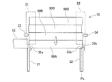
- the reference position Ps is a position where the stick 90 (preliminary stick 90B) that is guided by the guide device 20 and falls is received as the supply stick 90 (supply stick 90A) (see FIG. 5).
- the pressing position Pp is a position where the supply stick 90 (supply stick 90A) is pressed toward the front support member 31 by being advanced from the reference position Ps (see FIG. 6).
- the discharge position Px is a position at which the supply stick 90 (supply stick 90A) is discharged from between the front support member 31 by moving backward from the reference position Ps (see FIG. 7).
- the rear support member 32 has a support surface 32a and a pressing surface 32b as shown in FIG.
- the support surface 32a is formed horizontally and supports the lower surface of the rear end of the supply stick 90A at the reference position Ps.
- the pressing surface 32b of the rear support member 32 is formed to be orthogonal to the support surface 32a. The pressing surface 32b presses the rear end of the supply stick 90A at the pressing position Pp.
- the front support member 31 has a support surface 31 a arranged at the same vertical position as the support surface 32 a of the rear support member 32.
- the front support member 31 and the rear support member 32 support both ends so that the supply stick 90A is horizontal at the reference position Ps and the pressing position Pp.
- the drive device 40 includes a first solenoid valve 41, a second solenoid valve 42, an air pump 43, an air cylinder 44, a piston rod 45, a reverse spring 46, and a forward spring. 47.
- the first solenoid valve 41 and the second solenoid valve 42 are used for flow control of compressed air supplied from the air pump 43.
- the first solenoid valve 41 and the second solenoid valve 42 are configured to be independently operable.
- compressed air is circulated to the air cylinder 44. It is a normally closed type that supplies compressed air.
- the air pump 43 supplies compressed air to the first solenoid valve 41 and the second solenoid valve 42. The operation of the air pump 43 is controlled by the feeder controller 80.
- the air cylinder 44 is divided into a first air chamber 44 a and a second air chamber 44 b by a head portion 45 a formed on the piston rod 45. Compressed air is supplied to the first air chamber 44a via the first solenoid valve 41. Compressed air is supplied to the second air chamber 44b via the second solenoid valve 42.
- the piston rod 45 is supported so as to be movable in the axial direction of the air cylinder 44.
- the rear support member 32 is fixed to the end of the piston rod 45.
- the reverse spring 46 and the forward spring 47 are arranged on the outer peripheral side of the piston rod 45.
- the reverse spring 46 and the forward spring 47 urge the piston rod 45 in the axial direction so as to return the head portion 45a of the piston rod 45 to the neutral position. That is, according to the drive device 40 having the above-described configuration, the piston rod 45 is returned to the neutral position in a state where the two solenoids 41a and 42a are not excited. As a result, the rear support member 32 connected to the piston rod 45 is positioned at the reference position Ps.
- the first solenoid valve 41 when the solenoid 41a of the first solenoid valve 41 is excited by power feeding, the first solenoid valve 41 is opened. Thus, compressed air is supplied from the air pump 43 to the first air chamber 44a via the first solenoid valve 41. As a result, the piston rod 45 moves while compressing the reverse spring 46. As a result, the rear side support member 32 connected to the piston rod 45 is moved to the pressing position Pp advanced from the reference position Ps.
- the second solenoid valve 42 when the solenoid 42a of the second solenoid valve 42 is excited by power feeding, the second solenoid valve 42 is opened.
- compressed air is supplied from the air pump 43 to the second air chamber 44b via the second solenoid valve 42.
- the piston rod 45 moves while compressing the forward spring 47.
- the rear support member 32 connected to the piston rod 45 is moved to the discharge position Px that is retracted from the reference position Ps.
- the driving device 40 switches the first solenoid valve 41 that switches the three positions (the reference position Ps, the pressing position Pp, and the discharging position Px) of the rear support member 32 in accordance with the state of power supply to the two solenoids 41a and 42a. And a second solenoid valve 42.
- the driving device 40 is a solenoid valve that switches between three positions as a whole by combining two two-position valves (first solenoid valve 41 and second solenoid valve 42) that operate independently. It was supposed to be. On the other hand, you may apply the 3 position valve which switches 3 positions with two solenoids.
- the stick feeder 10 having the above-described configuration performs an exchange operation of the stick 90 when the supply stick 90A becomes empty, for example.
- the feeder control unit 80 recognizes that the rear end of the electronic component is closer to the supply position Pt side than the position where the component sensor 13 is arranged, and supplies the stick 90A for supply. Is determined to be empty.
- the drive device 40 of the stick support device 30 is in an unexcited state by cutting off the power supply to the solenoid 41a of the first solenoid valve 41. Thereby, supply of the compressed air to the air cylinder 44 is interrupted, and the piston rod 45 moves to the neutral position. As the piston rod 45 moves, the rear support member 32 moves backward from the pressing position Pp to the reference position Ps.
- the feeder control unit 80 recognizes that one or more spare sticks 90B are guided to the guide device 20 based on the detection result of a sensor (not shown).
- the guide device 20 allows the pair of pins 23 and 24 to enter the openings at both ends of the spare stick 90B, thereby restricting the vertical movement of the spare stick 90B. As a result, the one or more spare sticks 90B are prevented from falling.
- the stick support device 30 is energized by supplying power to the solenoid 42a of the second solenoid valve 42.
- compressed air is supplied to the air cylinder 44 via the second solenoid valve 42, and the rear support member 32 moves backward from the reference position Ps to the discharge position Px as shown in FIG.
- the interval between the front support member 31 and the rear support member 32 is wider than the length of the empty stick 90C, and the empty stick 90C is discharged.
- the stick support device 30 is not energized by cutting off the power supply to the solenoid 42a of the second solenoid valve 42. Thereby, supply of the compressed air to the air cylinder 44 is interrupted, and the piston rod 45 moves to the neutral position.
- the rear support member 32 moves forward from the discharge position Px to the reference position Ps as the piston rod 45 moves.
- the spare stick 90B falls.
- the dropped preliminary stick 90B is used as a supply stick 90 (new supply stick 90A) to be used next by the front support member 31 and the rear support member 32 at the reference position Ps. It is accepted.
- the distance between the rear end of the supply shooter 12 and the pressing surface 32b of the rear support member 32 is longer than that of the supply stick 90A.
- the stick support device 30 is energized by supplying power to the solenoid 41a of the first solenoid valve 41. Thereby, compressed air is supplied to the air cylinder 44 via the first solenoid valve 41, and the rear support member 32 advances from the reference position Ps to the pressing position Pp as shown in FIG. Then, the supply stick 90A is pressed toward the front support member 31 with the rear end in contact with the pressing surface 32b.
- the supply stick 90 ⁇ / b> A is moved to a position where the front end contacts the rear end of the supply shooter 12, and is sandwiched between the rear end surface of the supply shooter 12 and the pressing surface 32 b of the rear support member 32. Become. As a result, the supply stick 90A is connected to the supply shooter 12 so that electronic components can be circulated irrespective of variations in length.
- the stick 90 is exchanged as appropriate by repeating the above operation.
- control is performed such that the supply stick 90A is always pressed against the supply shooter 12. Further, when the position of the supply stick 90A pressed against the supply shooter 12 is held by, for example, a frictional force with the front support member 31, the rear support member 32 is moved to the reference position in the operating state. You may control to return to Ps.
- the stick feeder 10 pushes out an electronic component from the front end of a stick 90 that houses a plurality of electronic components, and supplies the electronic component.
- the stick feeder 10 includes a guide device 20 that guides the vertical movement in a state where a plurality of sticks 90 are stacked, a front support member 31 that supports both ends of the lowermost supply stick 90 among the plurality of sticks 90, and The rear support member 32 and the drive device 40 that moves the rear support member 32 in the longitudinal direction of the stick 90 are provided.
- the drive device 40 receives the stick 90 that is guided and dropped by the guide device 20 together with the front support member 31 for supply, and advances the stick 90 for supply toward the front support member 31 by moving forward from the reference position Ps.
- the rear support member 32 is moved to three positions: a pressing position Pp to be pressed, and a discharge position Px that is retracted from the reference position Ps and discharges the supply stick 90 from between the front support member 31.
- the stick feeder 10 presses the supply stick 90 to the front support member 31 side by the rear support member 32.
- the supply stick 90 is pressed against a member (the supply shooter 12 in this embodiment) whose front end is on the front side of the stick feeder 10. Therefore, regardless of the length of the stick 90, the supply stick 90 is suppressed from generating a gap with the guide path of the supply shooter 12. Therefore, the stick feeder 10 can allow the electronic components to be suitably moved while allowing a difference in length of the plurality of sticks 90.
- the drive device 40 includes solenoid valves (first solenoid valve 41 and second solenoid valve 42) that switch the three positions of the rear support member 32 in accordance with the state of power supply to the two solenoids 41a and 42a.
- solenoid valves first solenoid valve 41 and second solenoid valve 42
- the rear support member 32 can be reliably operated while reducing the manufacturing cost.
- the operation of switching the three positions (the reference position Ps, the pressing position Pp, and the discharging position Px) of the rear support member 32 can be reliably controlled.
- the driving device 40 sets the rear support member 32 as the reference position Ps in a state where the two solenoids 41a and 42a are not excited. According to such a configuration, power is not supplied to the two solenoids 41a and 42a when the falling standby stick 90 is received for supply. As a result, malfunction of the rear support member 32 can be prevented, and the falling standby stick 90 can be reliably received for supply.
- the rear support member 32 includes a support surface 32a that supports the lower surface of the rear end of the supply stick 90 at the reference position Ps, and a rear end of the supply stick 90 that is orthogonal to the support surface 32a and at the pressing position Pp. And a pressing surface 32b for pressing.
- the stick feeder 10 maintains the predetermined posture of the stick 90 by the support surface 32a (in this embodiment, the horizontal posture), while holding the stick 90 by the pressing surface 32b on the front support member 31 side. Can be reliably pressed. Therefore, the operation of the stick feeder 10 can be stabilized. Further, as compared with the configuration in which the support surface 32a is inclined, the posture of the stick 90 can be kept constant regardless of the length and the longitudinal position of the stick 90.
- the front support member 31 and the rear support member 32 support both ends so that the supply stick 90 is horizontal at the reference position Ps and the pressing position Pp.
- the difference in the length of the stick 90 particularly affects the generation of a gap with the supply shooter.
- the gap and angle at the connection portion between the supply shooter 12 and the stick 90 are eliminated, and the electronic It becomes possible to transfer the parts suitably.
- the drive device 40 is configured such that the piston rod 45 is returned to the neutral position and the rear support member 32 is set to the reference position Ps in a state where the two solenoids 41a and 42a are not excited.
- the drive device 40 may be configured such that the rear support member 32 is set to the pressing position Pp or the discharging position Px in a state where the two solenoids 41a and 42 are not excited.
- the supply stick 90A is pressed forward by the elastic force of the forward spring 47.
- the state where the supply stick 90A is pressed against the end of the supply shooter 12 can be maintained without supplying power to the two solenoids 41a and 42a.
- the driving device 40 is configured to switch the three positions (the reference position Ps, the pressing position Pp, and the discharging position Px) of the rear support member 32 by the operations of the first solenoid valve 41 and the second solenoid valve 42. It was.
- the drive device 40 can employ an actuator different from the solenoid valve.
- the driving device 40 may be configured to steplessly position the rear support member 32 in the front-rear direction position including the above three positions by the operation of the electric motor.
- the rear support member 32 has a planar support surface 32a and a pressing surface 32b.
- the rear side support member 32 can be appropriately set in a shape corresponding to the replacement function of the stick 90 and the pressing function of the stick 90 included in the stick support device 30.
- the rear support member 32 receives the preliminary stick 90B falling at the reference position Ps for supply, the rear support member 32 has an inclined surface that guides the upper surface of the pressing surface 32b so as to correct the deviation in the length direction of the preliminary stick 90B. It is good also as a structure formed.
- the pressing surface 32b of the rear support member 32 may be set to a shape corresponding to the opening shape of the end of the supply stick 90A in addition to the flat shape. Further, the pressing surface 32b may be formed of a material that prevents slipping with the end portion of the supply stick 90A or a cushioning material having a certain degree of elasticity. According to such a configuration, the stability of the operation when the rear support member 32 presses the supply stick 90A can be improved.
Landscapes
- Engineering & Computer Science (AREA)
- Manufacturing & Machinery (AREA)
- Microelectronics & Electronic Packaging (AREA)
- Supply And Installment Of Electrical Components (AREA)
Abstract
積み上げられる複数のスティック(90)の長さの相違を許容して、電子部品を好適に移送可能なスティックフィーダを提供することを目的とする。スティックフィーダの駆動装置(40)は、ガイド装置(20)に案内されて落下するスティック(90)を供給用として前側支持部材(31)とともに受け止める基準位置と、基準位置から前進させて供給用のスティック(90)を前側支持部材(31)側に押圧する押圧位置と、基準位置から後退させて供給用のスティック(90)を前側支持部材(31)との間から排出する排出位置との3位置に後側支持部材(32)を移動させる。
Description
本発明は、スティックフィーダに関するものである。
特許文献1には、複数のスティックを積み上げた状態で支持するスティックフィーダが開示されている。このスティックフィーダは、最下段の供給用のスティックの両端を支持する一対の支持部材を備える。スティックフィーダは、一対の支持部材の間隔を拡げて空になった供給用のスティックを排出し、また落下する予備のスティックを供給用として一対の支持部材により受け止めてスティックの交換を行う。
このようなスティックフィーダにおいて、積み上げられた複数のスティックの長さが相違すると、供給用のスティックの前端位置がスティックごとに変位することがある。そうすると、スティックの前端から押し出された電子部品が移送される供給シュータとスティックとの間に隙間が生じて、電子部品の移送に影響するおそれがある。
本発明は、このような事情に鑑みてなされたものであり、積み上げられる複数のスティックの長さの相違を許容して、電子部品を好適に移送可能なスティックフィーダを提供することを目的とする。
請求項1に係るスティックフィーダは、複数の電子部品を収容するスティックの前端から前記電子部品を押し出して、当該電子部品を供給する。スティックフィーダは、複数の前記スティックを積み上げた状態で上下方向の移動を案内するガイド装置と、複数の前記スティックのうち最下段の供給用の前記スティックの両端を支持する前側支持部材および後側支持部材と、前記後側支持部材を前記スティックの長手方向に移動させる駆動装置と、を備える。前記駆動装置は、前記ガイド装置に案内されて落下する前記スティックを供給用として前記前側支持部材とともに受け止める基準位置と、前記基準位置から前進させて供給用の前記スティックを前記前側支持部材側に押圧する押圧位置と、前記基準位置から後退させて供給用の前記スティックを前記前側支持部材との間から排出する排出位置との3位置に前記後側支持部材を移動させる。
請求項1に係る発明の構成によると、スティックフィーダは、供給用のスティックを後側支持部材により前側支持部材側に押圧する。これにより、供給用のスティックは、前端がスティックフィーダ10の前側にある部材に押し付けられる。よって、供給用のスティックは、スティックの長さに関わらず、供給シュータなどの電子部品が移送される通路との間における隙間の発生を抑制される。従って、スティックフィーダは、複数のスティックの長さの相違を許容して、電子部品を好適に移動可能とすることができる。
以下、本発明のスティックフィーダを具体化した実施形態について図面を参照して説明する。スティックフィーダは、部品実装機の部品供給装置を構成する。スティックフィーダは、複数の電子部品を収容するスティックの前端から電子部品を押し出して、当該電子部品を供給する。上記の部品実装機は、スティックフィーダにより供給された電子部品を保持部材により保持して、この電子部品を回路基板上の所定位置に装着する装置である。
<実施形態>
(スティックフィーダ10の概要)
スティックフィーダ10は、図1に示すように、部品実装機1の部品供給装置2のスロット2aに着脱可能にセットされる。セットされたスティックフィーダ10は、部品実装機1の本体から電力を供給されるとともに、部品実装機1の制御装置と通信可能な状態となる。スティックフィーダ10は、図2に示すように、複数のスティック90を積み上げた状態で支持する。
(スティックフィーダ10の概要)
スティックフィーダ10は、図1に示すように、部品実装機1の部品供給装置2のスロット2aに着脱可能にセットされる。セットされたスティックフィーダ10は、部品実装機1の本体から電力を供給されるとともに、部品実装機1の制御装置と通信可能な状態となる。スティックフィーダ10は、図2に示すように、複数のスティック90を積み上げた状態で支持する。
なお、本実施形態において、スティックフィーダ10は、スティック90を水平の姿勢で支持する。また、スティックフィーダ10は、供給用のスティック90が空となった場合に下方に落下させて排出する。そして、スティックフィーダ10は、積み上げられた予備のスティック90を落下させて、新たな供給用のスティック90として補給する落下型を採用する。
(スティック90の構成)
スティック90は、直線状の本体内に電子部品が1列に並べて収容する。スティック90の両端は、長手方向に開口するように形成されている。ここで、スティック90がスティックフィーダ10に支持された状態において、電子部品の供給側(図2の右上側)を前側、電子部品の反供給側(図2の左下側)を後側とする。スティック90は、後述する押出装置50により電子部品を押し出され、スティック90の前端から電子部品を排出する。
スティック90は、直線状の本体内に電子部品が1列に並べて収容する。スティック90の両端は、長手方向に開口するように形成されている。ここで、スティック90がスティックフィーダ10に支持された状態において、電子部品の供給側(図2の右上側)を前側、電子部品の反供給側(図2の左下側)を後側とする。スティック90は、後述する押出装置50により電子部品を押し出され、スティック90の前端から電子部品を排出する。
以下では、積み上げられた複数のスティック90のうち最下段に位置して、使用中にある供給用のスティック90を供給用スティック90Aとも称する。また、供給用スティック90Aに積み上げられた予備のスティック90を予備スティック90Bとも称する。また、空となった供給用スティック90Aが後述するスティック支持装置30により下方に排出されたスティック90を空スティック90Cとも称する。
(スティックフィーダ10の全体構成)
スティックフィーダ10は、図2に示すように、ケース11と、供給シュータ12と、部品センサ13と、ガイド装置20と、スティック支持装置30と、押出装置50と、部品保持装置60と、フィーダ制御部80とを備えて構成される。
スティックフィーダ10は、図2に示すように、ケース11と、供給シュータ12と、部品センサ13と、ガイド装置20と、スティック支持装置30と、押出装置50と、部品保持装置60と、フィーダ制御部80とを備えて構成される。
ケース11は、全体形状としては扁平な箱形状に形成される。ケース11は、長さの異なるスティックに対応するために、電子部品の移送方向(図2のY方向)に伸縮可能に構成される。具体的には、ケース11は、別部材である前側ケース部11aおよび後側ケース部11bにより構成される。前側ケース部11aおよび後側ケース部11bは、互いにスライド可能に組み付けられている。
供給シュータ12は、ケース11の前側(図2の右上側)の上部に配置される。供給シュータ12は、筒状に形成され、スティックフィーダ10により供給される電子部品の外形に対応した内面を有する。供給シュータ12の後端は、供給用スティック90Aの前端との間で電子部品を流通可能に連結される。供給シュータ12は、スティック90の前端から電子部品の供給位置Ptまで移送される電子部品を案内する案内路の一部を構成する。
部品センサ13は、供給シュータ12に設けられ、供給シュータ12内の所定位置における電子部品の有無を検出する。部品センサ13により電子部品が検出されない場合には、移送される1列の電子部品の最後尾が部品センサ13よりも前側に位置することになる。これにより、後述するフィーダ制御部80は、部品センサ13による検出結果に基づいて、供給用スティック90Aが空か否かを判定する。
ガイド装置20は、ケース11の上部において供給シュータ12の後側に配置される。ガイド装置20は、複数のスティック90を積み上げた状態で上下方向に移動を案内する。このガイド装置20は、一対のスティックガイド21,22と、一対のピン23,24とを有する(図5~図7を参照)。前側のスティックガイド21は、ケース11の前側ケース部11aに固定される。後側のスティックガイド22は、ケース11の後側ケース部11bに固定される。これにより、一対のスティックガイド21,22は、スティック90の長さに応じた間隔に調整可能に構成される。一対のスティックガイド21,22は、スティック90の端部を支持して、スティック90の長手方向および幅方向(図2のX方向)の移動を規制する。
一対のピン23,24は、図5~図7に示すように、一対のスティックガイド21,22に配置され、図示しないアクチュエータによってスティックフィーダ10の前後方向に進退可能に設けられる。一対のピン23,24は、複数のスティック90のうち供給用スティック90Aの一段上に位置する予備スティック90Bに対応する上下方向位置に配置される。一対のピン23,24は、アクチュエータにより予備スティック90Bの両端の開口へと進入されて、当該予備スティック90Bの落下を防止する。また、一対のピン23,24は、アクチュエータにより予備スティック90Bの両端の開口から退避されて、当該予備スティック90Bの落下を許容する。
スティック支持装置30は、複数のスティック90のうち最下段の供給用のスティック90(供給用スティック90A)の両端を支持する前側支持部材31と後側支持部材32とを有する。前側支持部材31は、前側のスティックガイド21の下方に配置され、ケース11に固定される。後側支持部材32は、後側のスティックガイド22の下方に配置される。
また、スティック支持装置30は、後側支持部材32をスティック90の長手方向に移動させる駆動装置40を有する。後側支持部材32は、駆動装置40のピストンロッド45に連結され、駆動装置40により移動可能に構成される。これにより、前側支持部材31と後側支持部材32との間隔が調整可能な構成となっている。スティック支持装置30の後側支持部材32および駆動装置40の詳細については後述する。
押出装置50は、供給用スティック90Aの後端側から図示しない押出部材を挿入して、供給用スティック90Aの前端から電子部品を押し出す。また、押出装置50は、供給用スティック90Aが空になった場合に、押出部材をさらに進出させて供給シュータ12に挿入する。これにより、押出装置50は、供給シュータ12内の電子部品を供給位置Ptまで移送可能に構成される。
部品保持装置60は、供給位置Ptまで移送された電子部品を供給可能に保持する。詳細には、部品保持装置60は、電子部品の種類に対応して当該電子部品を保持する。これにより、スティックフィーダ10は、外形の異なる電子部品を部品実装機1の部品移載装置が保持できるように、種々の電子部品に対応した供給が可能となる。部品保持装置60は、スティック90の前端から電子部品の供給位置Ptまで移送される電子部品を案内する案内路の一部を構成する。
フィーダ制御部80は、スティックフィーダ10における種々の動作を制御する。フィーダ制御部80のメモリには、電子部品の供給制御などにおいて実行されるファームウェアや補正量などの設定値が記憶されている。フィーダ制御部80は、部品供給装置2のスロット2aに通信可能に保持された状態において、外部入力される指令値に応じて押出装置50や部品保持装置60の移送動作を制御する。また、フィーダ制御部80は、部品センサ13による検出結果に基づいて、供給用スティック90Aが空か否かを判定する。フィーダ制御部80は、スティック支持装置30によるスティック90の交換動作を制御する。
(後側支持部材32および駆動装置40の詳細構成)
ここで、スティックフィーダ10は、上記のようにケース11が別部材(前側ケース部11aおよび後側ケース部11b)により構成され、長さの異なるタイプのスティック90を収容可能である。しかしながら、同じタイプのスティック90であっても長さにばらつきがある。そのため、ケース11の長さがスティック90のタイプ別に設定されてもスティック90の長さが相違すると、供給シュータ12の後端と供給用スティック90Aの前端との間に隙間が生じて、電子部品の移送に影響するおそれがある。
ここで、スティックフィーダ10は、上記のようにケース11が別部材(前側ケース部11aおよび後側ケース部11b)により構成され、長さの異なるタイプのスティック90を収容可能である。しかしながら、同じタイプのスティック90であっても長さにばらつきがある。そのため、ケース11の長さがスティック90のタイプ別に設定されてもスティック90の長さが相違すると、供給シュータ12の後端と供給用スティック90Aの前端との間に隙間が生じて、電子部品の移送に影響するおそれがある。
これに対応して、スティック支持装置30は、固定された前側支持部材31に対して移動可能な後側支持部材32と、当該後側支持部材32を駆動させる駆動装置40とを有する。これにより、スティック支持装置30は、本実施形態において、供給用のスティック90を交換する機能に加えて、供給用のスティック90を前側に押圧してスティック90の長さのばらつきに基づく隙間の発生を抑制する機能を備える構成としている。
具体的には、駆動装置40は、基準位置Ps、押圧位置Pp、および排出位置Pxとの3位置に後側支持部材32を移動させる。基準位置Psは、ガイド装置20に案内されて落下するスティック90(予備スティック90B)を供給用のスティック90(供給用スティック90A)として受け止める位置である(図5を参照)。
押圧位置Ppは、基準位置Psから前進させて供給用のスティック90(供給用スティック90A)を前側支持部材31側に押圧する位置である(図6を参照)。排出位置Pxは、基準位置Psから後退させて供給用のスティック90(供給用スティック90A)を前側支持部材31との間から排出する位置である(図7を参照)。
後側支持部材32は、本実施形態において、図3に示すように、支持面32aと押圧面32bとを有する。支持面32aは、水平に形成され、基準位置Psにおいて供給用スティック90Aの後端の下面を支持する。後側支持部材32の押圧面32bは、支持面32aに直交するように形成される。押圧面32bは、押圧位置Ppにおいて供給用スティック90Aの後端を押圧する。
また、前側支持部材31は、図5に示すように、後側支持部材32の支持面32aと同じ上下方向位置に配置された支持面31aを有する。このような構成により、前側支持部材31および後側支持部材32は、基準位置Psおよび押圧位置Ppにおいて、供給用スティック90Aが水平となるように両端を支持する。
駆動装置40は、図3および図4に示すように、第一ソレノイドバルブ41と、第二ソレノイドバルブ42と、エアポンプ43と、エアシリンダ44と、ピストンロッド45と、後退スプリング46と、前進スプリング47とを有する。第一ソレノイドバルブ41および第二ソレノイドバルブ42は、エアポンプ43から供給される圧縮エアの流通制御に用いられる。
第一ソレノイドバルブ41および第二ソレノイドバルブ42は、本実施形態において、独立して動作可能に構成され、それぞれのソレノイド41a,42aに給電された場合に圧縮エアを流通させて、エアシリンダ44に圧縮エアを供給するノーマルクローズタイプである。エアポンプ43は、第一ソレノイドバルブ41および第二ソレノイドバルブ42に対して圧縮エアを供給する。エアポンプ43は、フィーダ制御部80により動作を制御される。
エアシリンダ44は、ピストンロッド45に形成されたヘッド部45aによって、第一気室44aおよび第二気室44bに区画される。第一気室44aには、第一ソレノイドバルブ41を介して圧縮エアが供給される。第二気室44bには、第二ソレノイドバルブ42を介して圧縮エアが供給される。ピストンロッド45は、エアシリンダ44の軸方向に移動可能に支持される。ピストンロッド45の端部には、後側支持部材32が固定される。
後退スプリング46および前進スプリング47は、ピストンロッド45の外周側に配置される。後退スプリング46および前進スプリング47は、ピストンロッド45のヘッド部45aを中立位置に戻すようにピストンロッド45を軸方向に付勢する。つまり、上記のような構成からなる駆動装置40によると、2つのソレノイド41a,42aがともに励磁されていない状態において、ピストンロッド45は中立位置に戻される。結果として、ピストンロッド45に連結された後側支持部材32は、基準位置Psに位置決めされる。
また、例えば第一ソレノイドバルブ41のソレノイド41aが給電により励磁されると、第一ソレノイドバルブ41が開状態となる。これにより、第一ソレノイドバルブ41を介してエアポンプ43から第一気室44aに圧縮エアが供給される。これにより、ピストンロッド45が後退スプリング46を圧縮しながら移動する。結果として、ピストンロッド45に連結された後側支持部材32は、基準位置Psより前進した押圧位置Ppに移動される。
また、例えば第二ソレノイドバルブ42のソレノイド42aが給電により励磁されると、第二ソレノイドバルブ42が開状態となる。これにより、第二ソレノイドバルブ42を介してエアポンプ43から第二気室44bに圧縮エアが供給される。これにより、ピストンロッド45が前進スプリング47を圧縮しながら移動する。結果として、ピストンロッド45に連結された後側支持部材32は、基準位置Psより後退した排出位置Pxに移動される。
2つのソレノイド41a,42aへの給電が遮断されて、ともに励磁されていない状態となると、後退スプリング46および前進スプリング47の弾性力により第一気室44aおよび第二気室44bからエアが排出される。これにより、ピストンロッド45が中立位置に戻される。このように、駆動装置40は、2つのソレノイド41a,42aに対する給電の状態に応じて後側支持部材32の3位置(基準位置Ps、押圧位置Pp、排出位置Px)を切り換える第一ソレノイドバルブ41および第二ソレノイドバルブ42を備える。
なお、駆動装置40は、本実施形態において、独立して動作する2つの2位置バルブ(第一ソレノイドバルブ41、第二ソレノイドバルブ42)を組み合わせて、全体として3位置を切り換えるソレノイドバルブを構成するものとした。これに対して、2つのソレノイドにより3位置を切り換える3位置バルブを適用してもよい。
(スティック90の交換動作)
上記のような構成からなるスティックフィーダ10は、例えば供給用スティック90Aが空となった場合にスティック90の交換動作を行う。先ず、フィーダ制御部80は、部品センサ13による検出結果に基づいて、部品センサ13が配置された位置よりも電子部品の最後尾が供給位置Pt側にあることを認識して、供給用スティック90Aが空であると判定する。
上記のような構成からなるスティックフィーダ10は、例えば供給用スティック90Aが空となった場合にスティック90の交換動作を行う。先ず、フィーダ制御部80は、部品センサ13による検出結果に基づいて、部品センサ13が配置された位置よりも電子部品の最後尾が供給位置Pt側にあることを認識して、供給用スティック90Aが空であると判定する。
スティック支持装置30の駆動装置40は、第一ソレノイドバルブ41のソレノイド41aへの給電を遮断して励磁されていない状態とする。これにより、エアシリンダ44への圧縮エアの供給が遮断されて、ピストンロッド45が中立位置へと移動する。後側支持部材32は、ピストンロッド45の移動に伴って、押圧位置Ppから基準位置Psへと後退する。
また、フィーダ制御部80は、ガイド装置20に1つ以上の予備スティック90Bが案内されていることを図示しないセンサの検出結果に基づいて認識する。ガイド装置20は、一対のピン23,24を予備スティック90Bの両端の開口へと進入させて、予備スティック90Bの上下移動を規制する。これにより、一または複数の予備スティック90Bは、落下を防止された状態となる。
次に、スティック支持装置30は、第二ソレノイドバルブ42のソレノイド42aに給電して励磁された状態とする。これにより、第二ソレノイドバルブ42を介してエアシリンダ44に圧縮エアが供給されて、図7に示すように、後側支持部材32は、基準位置Psから排出位置Pxへと後退する。そうすると、前側支持部材31と後側支持部材32の間隔が空スティック90Cの長さよりも拡がって、空スティック90Cが排出される。
続いて、スティック支持装置30は、第二ソレノイドバルブ42のソレノイド42aへの給電を遮断して励磁されていない状態とする。これにより、エアシリンダ44への圧縮エアの供給が遮断されて、ピストンロッド45が中立位置へと移動する。後側支持部材32は、ピストンロッド45の移動に伴って、排出位置Pxから基準位置Psへと前進する。
この状態において、ガイド装置20が一対のピン23,24を予備スティック90Bの両端の開口から退避させると、予備スティック90Bが落下する。落下した予備スティック90Bは、図5に示すように、前側支持部材31および基準位置Psにある後側支持部材32によって、次に使用される供給用のスティック90(新たな供給用スティック90A)として受け止められる。このとき、供給シュータ12の後端と後側支持部材32の押圧面32bとの間隔は、供給用スティック90Aよりも長い。
スティック支持装置30は、第一ソレノイドバルブ41のソレノイド41aに給電して励磁された状態とする。これにより、第一ソレノイドバルブ41を介してエアシリンダ44に圧縮エアが供給されて、図6に示すように、後側支持部材32は、基準位置Psから押圧位置Ppへと前進する。そうすると、供給用スティック90Aは、後端が押圧面32bと接触して前側支持部材31側へと押圧される。
結果として、供給用スティック90Aは、前端が供給シュータ12の後端に接触する位置まで移動され、供給シュータ12の後端面と後側支持部材32の押圧面32bとの間に挟み込まれた状態となる。これにより、供給用スティック90Aは、長さのばらつきによらず、供給シュータ12に対して電子部品を流通可能に連結される。
上記のような動作を繰り返すことによって、スティック90の交換が適宜実行される。なお、スティックフィーダ10が電子部品を供給する稼働状態においては、供給用スティック90Aを供給シュータ12に常時押し付けるように制御する。また、供給シュータ12側へと押し付けられた供給用スティック90Aの位置が、例えば前側支持部材31との間の摩擦力などによって保持される場合には、稼働状態において後側支持部材32を基準位置Psに戻すように制御してもよい。
(実施形態の構成による効果)
スティックフィーダ10は、複数の電子部品を収容するスティック90の前端から電子部品を押し出して、当該電子部品を供給する。スティックフィーダ10は、複数のスティック90を積み上げた状態で上下方向の移動を案内するガイド装置20と、複数のスティック90のうち最下段の供給用のスティック90の両端を支持する前側支持部材31および後側支持部材32と、後側支持部材32をスティック90の長手方向に移動させる駆動装置40と、を備える。
駆動装置40は、ガイド装置20に案内されて落下するスティック90を供給用として前側支持部材31とともに受け止める基準位置Psと、基準位置Psから前進させて供給用のスティック90を前側支持部材31側に押圧する押圧位置Ppと、基準位置Psから後退させて供給用のスティック90を前側支持部材31との間から排出する排出位置Pxとの3位置に後側支持部材32を移動させる。
スティックフィーダ10は、複数の電子部品を収容するスティック90の前端から電子部品を押し出して、当該電子部品を供給する。スティックフィーダ10は、複数のスティック90を積み上げた状態で上下方向の移動を案内するガイド装置20と、複数のスティック90のうち最下段の供給用のスティック90の両端を支持する前側支持部材31および後側支持部材32と、後側支持部材32をスティック90の長手方向に移動させる駆動装置40と、を備える。
駆動装置40は、ガイド装置20に案内されて落下するスティック90を供給用として前側支持部材31とともに受け止める基準位置Psと、基準位置Psから前進させて供給用のスティック90を前側支持部材31側に押圧する押圧位置Ppと、基準位置Psから後退させて供給用のスティック90を前側支持部材31との間から排出する排出位置Pxとの3位置に後側支持部材32を移動させる。
このような構成によると、スティックフィーダ10は、供給用のスティック90を後側支持部材32により前側支持部材31側に押圧する。これにより、供給用のスティック90は、前端がスティックフィーダ10の前側にある部材(本実施形態においては、供給シュータ12)に押し付けられる。よって、供給用のスティック90は、スティック90の長さに関わらず、供給シュータ12の案内路との間における隙間の発生を抑制される。従って、スティックフィーダ10は、複数のスティック90の長さの相違を許容して、電子部品を好適に移動可能とすることができる。
また、駆動装置40は、2つのソレノイド41a,42aに対する給電の状態に応じて後側支持部材32の3位置を切り換えるソレノイドバルブ(第一ソレノイドバルブ41、第二ソレノイドバルブ42)を有する。
このような構成によると、2つのソレノイド41a,42aにより後側支持部材32の位置を切り換える構成とするため、製造コストを低減しつつ確実に後側支持部材32を動作させることができる。また、2つのソレノイド41a,42aとすることにより、後側支持部材32の3位置(基準位置Ps、押圧位置Pp、排出位置Px)を切り換える動作を確実に制御することができる。
このような構成によると、2つのソレノイド41a,42aにより後側支持部材32の位置を切り換える構成とするため、製造コストを低減しつつ確実に後側支持部材32を動作させることができる。また、2つのソレノイド41a,42aとすることにより、後側支持部材32の3位置(基準位置Ps、押圧位置Pp、排出位置Px)を切り換える動作を確実に制御することができる。
また、駆動装置40は、2つのソレノイド41a,42aがともに励磁されていない状態において、後側支持部材32を基準位置Psとする。
このような構成によると、落下する予備のスティック90を供給用として受け止める際に2つのソレノイド41a,42aに電力が供給されない。これにより、後側支持部材32の誤動作を防止でき、落下する予備のスティック90を供給用として確実に受け止めることができる。
このような構成によると、落下する予備のスティック90を供給用として受け止める際に2つのソレノイド41a,42aに電力が供給されない。これにより、後側支持部材32の誤動作を防止でき、落下する予備のスティック90を供給用として確実に受け止めることができる。
また、後側支持部材32は、基準位置Psにおいて供給用のスティック90の後端の下面を支持する支持面32aと、支持面32aに直交し且つ押圧位置Ppにおいて供給用のスティック90の後端を押圧する押圧面32bと、を有する。
このような構成によると、スティックフィーダ10は、支持面32aによりスティック90の所定の姿勢(本実施形態においては、水平な姿勢)を維持しつつ、押圧面32bによりスティック90を前側支持部材31側に確実に押圧することができる。よって、スティックフィーダ10の動作の安定化を図ることができる。また、支持面32aが傾斜している構成と比較すると、スティック90の長さおよび長手方向位置に関わらず、スティック90の姿勢を一定に維持できる。
このような構成によると、スティックフィーダ10は、支持面32aによりスティック90の所定の姿勢(本実施形態においては、水平な姿勢)を維持しつつ、押圧面32bによりスティック90を前側支持部材31側に確実に押圧することができる。よって、スティックフィーダ10の動作の安定化を図ることができる。また、支持面32aが傾斜している構成と比較すると、スティック90の長さおよび長手方向位置に関わらず、スティック90の姿勢を一定に維持できる。
また、前側支持部材31および後側支持部材32は、基準位置Psおよび押圧位置Ppにおいて、供給用のスティック90が水平となるように両端を支持する。
ここで、スティック90をほぼ水平な姿勢で支持する落下型のスティックフィーダ10においては、特にスティック90の長さの相違が供給シュータとの間の隙間の発生に影響する。これに対して、本実施形態の構成のように、スティック90が水平となる姿勢で支持される構成とすることにより、供給シュータ12とスティック90との連結部位の隙間および角度をなくして、電子部品を好適に移送することが可能となる。
ここで、スティック90をほぼ水平な姿勢で支持する落下型のスティックフィーダ10においては、特にスティック90の長さの相違が供給シュータとの間の隙間の発生に影響する。これに対して、本実施形態の構成のように、スティック90が水平となる姿勢で支持される構成とすることにより、供給シュータ12とスティック90との連結部位の隙間および角度をなくして、電子部品を好適に移送することが可能となる。
<実施形態の変形態様>
(駆動装置40について)
実施形態において、駆動装置40は、2つのソレノイド41a,42aがともに励磁されていない状態において、ピストンロッド45が中立位置に戻されて、後側支持部材32を基準位置Psとする構成とした。これに対して、駆動装置40は、2つのソレノイド41a,42がともに励磁されていない状態において、後側支持部材32を押圧位置Ppまたは排出位置Pxとする構成としてもよい。
(駆動装置40について)
実施形態において、駆動装置40は、2つのソレノイド41a,42aがともに励磁されていない状態において、ピストンロッド45が中立位置に戻されて、後側支持部材32を基準位置Psとする構成とした。これに対して、駆動装置40は、2つのソレノイド41a,42がともに励磁されていない状態において、後側支持部材32を押圧位置Ppまたは排出位置Pxとする構成としてもよい。
例えば、駆動装置40が上記の状態において後側支持部材32を押圧位置Ppとする構成によると、前進スプリング47の弾性力によって供給用スティック90Aが前側に押圧される。これにより、スティックフィーダ10の稼働状態において、2つのソレノイド41a,42aに給電することなく、供給用スティック90Aが供給シュータ12の端部に押し付けられた状態を維持することができる。
また、実施形態において、駆動装置40は、第一ソレノイドバルブ41および第二ソレノイドバルブ42の動作によって、後側支持部材32の3位置(基準位置Ps、押圧位置Pp、排出位置Px)を切り換える構成とした。これに対して、駆動装置40は、ソレノイドバルブとは異なるアクチュエータを採用することができる。例えば、駆動装置40は、電動モータの動作によって後側支持部材32を上記の3位置を含む前後方向位置に無段階で位置決めする構成としてもよい。
(後側支持部材32について)
実施形態において、後側支持部材32は、平面状の支持面32aおよび押圧面32bを有する構成とした。これに対して、後側支持部材32は、スティック支持装置30が備えるスティック90の交換機能およびスティック90の押圧機能に応じた形状に適宜設定され得る。例えば、後側支持部材32は、基準位置Psにおいて落下する予備スティック90Bを供給用として受け止める際に、予備スティック90Bの長さ方向のずれを補正するように案内する斜面を押圧面32bの上部に形成される構成としてもよい。
実施形態において、後側支持部材32は、平面状の支持面32aおよび押圧面32bを有する構成とした。これに対して、後側支持部材32は、スティック支持装置30が備えるスティック90の交換機能およびスティック90の押圧機能に応じた形状に適宜設定され得る。例えば、後側支持部材32は、基準位置Psにおいて落下する予備スティック90Bを供給用として受け止める際に、予備スティック90Bの長さ方向のずれを補正するように案内する斜面を押圧面32bの上部に形成される構成としてもよい。
また、後側支持部材32の押圧面32bは、平面状の他に、供給用スティック90Aの端部の開口形状に対応した形状に設定されるようにしてもよい。また、押圧面32bは、供給用スティック90Aの端部との滑りを防止する材料や、ある程度の弾性を有する緩衝材により形成されるようにしてもよい。このような構成によると、後側支持部材32が供給用スティック90Aを押圧した際の動作の安定性を向上できる。
1:部品実装機、 2:部品供給装置、 2a:スロット
10:スティックフィーダ
11:ケース、 11a:前側ケース部、 11b:後側ケース部
12:供給シュータ、 13:部品センサ
20:ガイド装置
21,22:スティックガイド、 23,24:ピン
30:スティック支持装置
31:前側支持部材、 31a:支持面
32:後側支持部材、 32a:支持面、 32b:押圧面
40:駆動装置
41:第一ソレノイドバルブ、 41a:ソレノイド
42:第二ソレノイドバルブ、 42a:ソレノイド
43:エアポンプ、 44:エアシリンダ
44a:第一気室、 44b:第二気室
45:ピストンロッド、 45a:ヘッド部
46:後退スプリング、 47:前進スプリング47
50:押出装置
60:部品保持装置
80:フィーダ制御部
90:スティック
90A:供給用スティック、 90B:予備スティック
90C:空スティック
Pt:(電子部品の)供給位置
Ps:基準位置、 Pp:押圧位置、 Px:排出位置
10:スティックフィーダ
11:ケース、 11a:前側ケース部、 11b:後側ケース部
12:供給シュータ、 13:部品センサ
20:ガイド装置
21,22:スティックガイド、 23,24:ピン
30:スティック支持装置
31:前側支持部材、 31a:支持面
32:後側支持部材、 32a:支持面、 32b:押圧面
40:駆動装置
41:第一ソレノイドバルブ、 41a:ソレノイド
42:第二ソレノイドバルブ、 42a:ソレノイド
43:エアポンプ、 44:エアシリンダ
44a:第一気室、 44b:第二気室
45:ピストンロッド、 45a:ヘッド部
46:後退スプリング、 47:前進スプリング47
50:押出装置
60:部品保持装置
80:フィーダ制御部
90:スティック
90A:供給用スティック、 90B:予備スティック
90C:空スティック
Pt:(電子部品の)供給位置
Ps:基準位置、 Pp:押圧位置、 Px:排出位置
Claims (5)
- 複数の電子部品を収容するスティックの前端から前記電子部品を押し出して、当該電子部品を供給するスティックフィーダであって、
複数の前記スティックを積み上げた状態で上下方向の移動を案内するガイド装置と、
複数の前記スティックのうち最下段の供給用の前記スティックの両端を支持する前側支持部材および後側支持部材と、
前記後側支持部材を前記スティックの長手方向に移動させる駆動装置と、を備え、
前記駆動装置は、前記ガイド装置に案内されて落下する前記スティックを供給用として前記前側支持部材とともに受け止める基準位置と、前記基準位置から前進させて供給用の前記スティックを前記前側支持部材側に押圧する押圧位置と、前記基準位置から後退させて供給用の前記スティックを前記前側支持部材との間から排出する排出位置との3位置に前記後側支持部材を移動させるスティックフィーダ。 - 前記駆動装置は、2つのソレノイドに対する給電の状態に応じて前記後側支持部材の前記3位置を切り換えるソレノイドバルブを有する、請求項1に記載のスティックフィーダ。
- 前記駆動装置は、2つの前記ソレノイドがともに励磁されていない状態において、前記後側支持部材を前記基準位置とする、請求項2に記載のスティックフィーダ。
- 前記後側支持部材は、前記基準位置において供給用の前記スティックの後端の下面を支持する支持面と、前記支持面に直交し且つ前記押圧位置において供給用の前記スティックの後端を押圧する押圧面と、を有する、請求項1-3の何れか一項に記載のスティックフィーダ。
- 前記前側支持部材および前記後側支持部材は、前記基準位置および前記押圧位置において、供給用の前記スティックが水平となるように両端を支持する、請求項4に記載のスティックフィーダ。
Priority Applications (3)
| Application Number | Priority Date | Filing Date | Title |
|---|---|---|---|
| PCT/JP2015/076314 WO2017046898A1 (ja) | 2015-09-16 | 2015-09-16 | スティックフィーダ |
| JP2017540396A JP6898851B2 (ja) | 2015-09-16 | 2015-09-16 | スティックフィーダ |
| JP2021069863A JP7307118B2 (ja) | 2015-09-16 | 2021-04-16 | スティックフィーダ |
Applications Claiming Priority (1)
| Application Number | Priority Date | Filing Date | Title |
|---|---|---|---|
| PCT/JP2015/076314 WO2017046898A1 (ja) | 2015-09-16 | 2015-09-16 | スティックフィーダ |
Publications (1)
| Publication Number | Publication Date |
|---|---|
| WO2017046898A1 true WO2017046898A1 (ja) | 2017-03-23 |
Family
ID=58288296
Family Applications (1)
| Application Number | Title | Priority Date | Filing Date |
|---|---|---|---|
| PCT/JP2015/076314 Ceased WO2017046898A1 (ja) | 2015-09-16 | 2015-09-16 | スティックフィーダ |
Country Status (2)
| Country | Link |
|---|---|
| JP (2) | JP6898851B2 (ja) |
| WO (1) | WO2017046898A1 (ja) |
Cited By (2)
| Publication number | Priority date | Publication date | Assignee | Title |
|---|---|---|---|---|
| JP2022050160A (ja) * | 2020-09-17 | 2022-03-30 | パナソニックIpマネジメント株式会社 | スティックフィーダ、スティックフィーダの制御方法、部品装着装置、および部品実装方法 |
| EP4294143A1 (en) * | 2022-06-14 | 2023-12-20 | BIOTRONIK SE & Co. KG | Feeding arrangement for an automated placement machine for the manufacturing of electronic devices |
Citations (4)
| Publication number | Priority date | Publication date | Assignee | Title |
|---|---|---|---|---|
| JPH04206698A (ja) * | 1990-11-30 | 1992-07-28 | Fujitsu Denso Ltd | 電子部品収納装置 |
| JPH07228333A (ja) * | 1994-02-14 | 1995-08-29 | Toshiba Corp | 部品供給装置 |
| JPH10149224A (ja) * | 1996-11-15 | 1998-06-02 | Nishikawa Rubber Co Ltd | 圧力調整弁の安全装置 |
| JPH10159813A (ja) * | 1996-11-28 | 1998-06-16 | Sekisui Chem Co Ltd | エア駆動機器の安全停止機構 |
Family Cites Families (6)
| Publication number | Priority date | Publication date | Assignee | Title |
|---|---|---|---|---|
| JPH05206685A (ja) * | 1992-01-27 | 1993-08-13 | Matsushita Electric Ind Co Ltd | 電子部品供給装置 |
| JP2705495B2 (ja) * | 1992-12-18 | 1998-01-28 | 株式会社デンソー | 部品押出し装置 |
| JPH07251331A (ja) * | 1994-03-16 | 1995-10-03 | Canon Inc | 電子部品の供給装置 |
| JP3807520B2 (ja) * | 1997-05-12 | 2006-08-09 | 日本エス・エム・テー株式会社 | 部品供給装置 |
| US20020067980A1 (en) | 1999-06-21 | 2002-06-06 | Richard D. Havich | Component feeder |
| JP4530580B2 (ja) | 2001-05-30 | 2010-08-25 | 株式会社日立ハイテクインスツルメンツ | 電子部品装着装置 |
-
2015
- 2015-09-16 JP JP2017540396A patent/JP6898851B2/ja active Active
- 2015-09-16 WO PCT/JP2015/076314 patent/WO2017046898A1/ja not_active Ceased
-
2021
- 2021-04-16 JP JP2021069863A patent/JP7307118B2/ja active Active
Patent Citations (4)
| Publication number | Priority date | Publication date | Assignee | Title |
|---|---|---|---|---|
| JPH04206698A (ja) * | 1990-11-30 | 1992-07-28 | Fujitsu Denso Ltd | 電子部品収納装置 |
| JPH07228333A (ja) * | 1994-02-14 | 1995-08-29 | Toshiba Corp | 部品供給装置 |
| JPH10149224A (ja) * | 1996-11-15 | 1998-06-02 | Nishikawa Rubber Co Ltd | 圧力調整弁の安全装置 |
| JPH10159813A (ja) * | 1996-11-28 | 1998-06-16 | Sekisui Chem Co Ltd | エア駆動機器の安全停止機構 |
Cited By (3)
| Publication number | Priority date | Publication date | Assignee | Title |
|---|---|---|---|---|
| JP2022050160A (ja) * | 2020-09-17 | 2022-03-30 | パナソニックIpマネジメント株式会社 | スティックフィーダ、スティックフィーダの制御方法、部品装着装置、および部品実装方法 |
| JP7457919B2 (ja) | 2020-09-17 | 2024-03-29 | パナソニックIpマネジメント株式会社 | スティックフィーダ、スティックフィーダの制御方法、部品装着装置、および部品実装方法 |
| EP4294143A1 (en) * | 2022-06-14 | 2023-12-20 | BIOTRONIK SE & Co. KG | Feeding arrangement for an automated placement machine for the manufacturing of electronic devices |
Also Published As
| Publication number | Publication date |
|---|---|
| JP2021119613A (ja) | 2021-08-12 |
| JPWO2017046898A1 (ja) | 2018-06-28 |
| JP6898851B2 (ja) | 2021-07-07 |
| JP7307118B2 (ja) | 2023-07-11 |
Similar Documents
| Publication | Publication Date | Title |
|---|---|---|
| JP7307118B2 (ja) | スティックフィーダ | |
| CN106031325B (zh) | 供料器更换装置 | |
| JP6545677B2 (ja) | テープフィーダ | |
| KR20210152424A (ko) | 잉크젯 기록 장치 | |
| JP6441920B2 (ja) | テープフィーダ | |
| JP2007054835A (ja) | レーザ加工装置 | |
| JP2024095031A (ja) | ファスナ供給装置、ファスナ供給システム、及びファスナ供給方法 | |
| US10214032B2 (en) | Printing apparatus | |
| KR20120013305A (ko) | 워크 공급 장치 및 이 워크 공급 장치를 갖춘 공작기계 | |
| JP2002096122A (ja) | パンチプレス | |
| WO2016103334A1 (ja) | スティックフィーダ | |
| CN102427716B (zh) | 一种料盒供料机构 | |
| CN217563859U (zh) | 毛刷自动更换装置和线路板加工设备 | |
| JP2008302488A (ja) | 部品供給方法及び部品供給ヘッド | |
| KR20160007257A (ko) | 제함기용 박스공급장치 | |
| JPWO2017046897A1 (ja) | スティックフィーダ | |
| WO2012086752A1 (ja) | 部品収納スティック入替装置及び部品収納スティック入替方法 | |
| JP6762199B2 (ja) | 搬出装置 | |
| US8434204B2 (en) | Apparatus and method for trimming | |
| TWI609740B (zh) | 連續式供料設備 | |
| CN220427414U (zh) | 智能型多料道螺丝供给机 | |
| KR101617996B1 (ko) | 봉재 공급기 | |
| JP6984681B2 (ja) | 打ち込み工具 | |
| JP2008153557A (ja) | リードフレーム供給装置 | |
| JP7333601B2 (ja) | スポット溶接用電極供給装置 |
Legal Events
| Date | Code | Title | Description |
|---|---|---|---|
| 121 | Ep: the epo has been informed by wipo that ep was designated in this application |
Ref document number: 15904087 Country of ref document: EP Kind code of ref document: A1 |
|
| ENP | Entry into the national phase |
Ref document number: 2017540396 Country of ref document: JP Kind code of ref document: A |
|
| NENP | Non-entry into the national phase |
Ref country code: DE |
|
| 122 | Ep: pct application non-entry in european phase |
Ref document number: 15904087 Country of ref document: EP Kind code of ref document: A1 |