WO2017043347A1 - 張力調整機構および張力制御装置 - Google Patents
張力調整機構および張力制御装置 Download PDFInfo
- Publication number
- WO2017043347A1 WO2017043347A1 PCT/JP2016/075112 JP2016075112W WO2017043347A1 WO 2017043347 A1 WO2017043347 A1 WO 2017043347A1 JP 2016075112 W JP2016075112 W JP 2016075112W WO 2017043347 A1 WO2017043347 A1 WO 2017043347A1
- Authority
- WO
- WIPO (PCT)
- Prior art keywords
- tension
- web
- roll
- rotational force
- arm portion
- Prior art date
- Legal status (The legal status is an assumption and is not a legal conclusion. Google has not performed a legal analysis and makes no representation as to the accuracy of the status listed.)
- Ceased
Links
Images



Classifications
-
- B—PERFORMING OPERATIONS; TRANSPORTING
- B65—CONVEYING; PACKING; STORING; HANDLING THIN OR FILAMENTARY MATERIAL
- B65H—HANDLING THIN OR FILAMENTARY MATERIAL, e.g. SHEETS, WEBS, CABLES
- B65H23/00—Registering, tensioning, smoothing or guiding webs
- B65H23/04—Registering, tensioning, smoothing or guiding webs longitudinally
-
- B—PERFORMING OPERATIONS; TRANSPORTING
- B65—CONVEYING; PACKING; STORING; HANDLING THIN OR FILAMENTARY MATERIAL
- B65H—HANDLING THIN OR FILAMENTARY MATERIAL, e.g. SHEETS, WEBS, CABLES
- B65H23/00—Registering, tensioning, smoothing or guiding webs
- B65H23/04—Registering, tensioning, smoothing or guiding webs longitudinally
- B65H23/18—Registering, tensioning, smoothing or guiding webs longitudinally by controlling or regulating the web-advancing mechanism, e.g. mechanism acting on the running web
- B65H23/188—Registering, tensioning, smoothing or guiding webs longitudinally by controlling or regulating the web-advancing mechanism, e.g. mechanism acting on the running web in connection with running-web
- B65H23/192—Registering, tensioning, smoothing or guiding webs longitudinally by controlling or regulating the web-advancing mechanism, e.g. mechanism acting on the running web in connection with running-web motor-controlled
Definitions
- the present invention relates to a tension adjusting mechanism and a tension control device for adjusting the tension of a continuously running web.
- Tension control is indispensable for continuously conveying webs such as plastic films and nonwoven fabrics, and dancer rolls are generally used for web tension control (described in Patent Document 1).
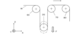
- Fig. 9 shows a conventional dancer roll mechanism.
- the web W is wound around a rotatable dancer roll 30 that is movable up and down between a guide roll 60 and a guide roll 70 that are fixedly arranged and rotatable.
- the tension applied to the web W is kept constant by applying a constant load F to the lower side of the dancer roll 30.
- FIG. 10 a configuration as shown in which the load applied to the dancer roll 30 can be changed so that the tension can be arbitrarily set according to the type and thickness of the web W is well known.
- the dancer roll 30 is provided at the end of the arm 20 that swings around the rotation axis 20 ⁇ / b> A, and a load is applied to the dancer roll 30 by the cylinder 40 applying a rotational force to the dancer arm 20. Since the force generated by the cylinder 40 can be varied by adjusting the pressure in the cylinder, the load applied to the dancer roll 30 can be changed.
- a so-called roll-to-roll process in which various processes are performed while continuously conveying a web is used for various web materials.
- tension control has increased, and the need for precise tension control in various processes from unwinding to winding has increased.
- the present invention has been made in view of the above problems, and provides a tension adjusting mechanism and a tension control device that are excellent in responsiveness even in low-tension conveyance of a web and have few restrictions on arrangement.
- the invention described in claim 2 The arm portion is symmetrical about the axis of rotation;
- the invention according to claim 3
- the drive mechanism generates a rotational force;
- the tension adjusting mechanism according to claim 1, wherein the rotation shaft is coupled to the drive mechanism.
- the invention according to claim 4 The tension adjusting mechanism according to claim 3, wherein the driving mechanism includes a powder clutch.
- the tension adjusting mechanism according to any one of claims 1 to 4, A tension sensor that measures the tension of the web being continuously conveyed; And a control unit that adjusts a rotational force applied to the arm unit according to a measurement value of the tension sensor.
- the tension adjusting mechanism and the tension control device of the present invention can perform tension control with excellent responsiveness even in the low tension conveyance of the web without requiring a large installation space.
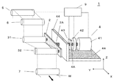
- FIG. 1 is a diagram illustrating the configuration of a tension control device 1 according to an embodiment of the present invention.
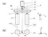
- FIG. 2 shows a tension adjustment mechanism 10 in the tension control device 1.
- the tension control device 1 is provided in the web W conveyance line.
- the long web W is conveyed in a direction from the upper left to the lower right, and the roll 5 is a rotatable roll having a tension sensor function. Tension is adjusted between the rolls 7 on the downstream side.
- FIG. 2 shows a portion of the tension adjusting mechanism 10 extracted from the tension control device 1 of FIG. 1, FIG. 2 (a) is a top view (Z-axis direction), and FIG. 2 (b) is a web. It is seen from the side (Y-axis direction) with respect to the conveyance direction of W.
- the tension adjustment mechanism 10 includes an arm unit 2, a roll 31, a roll 32, and a drive mechanism 4.
- the arm portion 2 is capable of swinging around the rotating shaft 2A, and obtains rotational force by the drive mechanism 4.
- rotational force said here is synonymous with a torque.
- the roll 31 and the roll 32 are attached to the arm unit 2 so as to be rotatable around the rotary shaft 31A and the rotary shaft 32A.
- the direction contacting the upstream web W is referred to as a roll 31
- the direction contacting the downstream web is referred to as a roll 32.
- the drive mechanism 4 is fixed to a fixed base 44 with a drive source 41, a drive force transmission mechanism 42, and an angle meter 43 as constituent elements.
- the drive source 41 is a motor that generates a rotational force, and the rotational force is transmitted to the rotational shaft 2A of the arm portion 2 via the rotational shaft 4A, but is rotated by the driving force transmission mechanism 42 such as a powder clutch.
- the rotational force applied to the shaft 2A can be adjusted.
- the drive source 41 has a function of varying the rotational force
- the drive force transmission mechanism 42 can be omitted.
- the goniometer 43 has a function of measuring the rotation angle of the rotation shaft 2 ⁇ / b> A (inclination angle with respect to the rotation base 44).
- the tension adjusting mechanism 10 can change the tension of the web W as will be described later, but in order to control it to a desired value, it is desirable to control it in combination with a tension sensor. Therefore, in the control device 1 according to the embodiment shown in FIG. 1, the upstream roll 5 has a function of a tension sensor and includes a control unit 9.
- the control unit 9 is connected to the drive source 41, the drive force transmission mechanism 42, and the roll 5, reads the tension value measured by the roll 5, controls the drive source 41 and the drive force transmission mechanism 42, and has an angle meter 43. It also has a function to read the measured values.
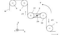
- FIGS. 3 to 5 are views seen from the side (Y-axis direction) with respect to the web W conveyance direction.
- the web W passes through the roll 5 and the roll 6, is wound around the roll 31 and the roll 32 in an S shape, and is conveyed toward the roll 7.
- the web W unwinding mechanism on the upstream side of the roll 5
- FIG. 3 shows a state in which the web is stabilized at a predetermined tension by FT.
- a rotational force T is constantly applied to the rotating shaft 2 ⁇ / b> A of the arm portion 2.
- This rotational force T gives FT as tension to the web W wound around the roll 31 and the roll 32.
- the rotational force T applied to the rotating shaft 2A is kept constant by the drive source 41 and the drive force transmission mechanism 42, if the web W is in a steady state, the web tension is also kept constant at FT. Kept.
- FIG. 3 shows a case where the conveyance of the web W is maintained in a steady state, but the tension of the web W may actually fluctuate due to expansion / contraction of the web W, fluctuation of the conveyance speed, or the like.
- FIG. 4 and FIG. 5 show the state when such tension fluctuation occurs.
- FIG. 4 shows a case where the tension of the web W becomes lower than the FT for some reason, and the balance between the tension of the web W and the tension generated by the rotational force T is lost.
- Tilt force works counterclockwise.
- a force that increases the tension of the web W between the roll 6 and the roll 31 works, and similarly, a force that increases the tension of the web W between the roll 32 and the roll 7. Work. That is, the tension drop of the web W is corrected.
- FIG. 5 shows a case where the tension of the web W is higher than that of the FT, and the balance between the tension of the web W and the tension generated by the rotational force T is lost.
- the tilting force works.
- the tension of the web W between the roll 6 and the roll 31 is weakened, and similarly, the tension of the web W between the roll 32 and the roll 7 is weakened. That is, the increase in the tension of the web W is corrected.
- the wrapping angle of the web W with respect to the roll 31 and the roll 32 is different from that in FIG. 3.
- the tension applied to the web W wound around the roll 31 and the roll 32 by the rotational force T is also different between the state of FIG. 3 and the states of FIGS.
- An example thereof is the tension control device 1 of FIG. 1, in which the control unit 9 controls the rotational force T applied to the rotary shaft 2 ⁇ / b> A of the arm unit 2 in accordance with the measurement value of the tension sensor provided on the roll 5. Yes.
- the drive force transmission mechanism 42 may be controlled, but the output of the drive source 41 may be controlled as necessary.
- the tension sensor provided on the roll 5 in this embodiment measures the force applied to the roll by the web W and converts it into tension, and it is not preferable that the winding state of the web W changes. 3 to 5, the upstream roll 6 is arranged further upstream. However, as shown in FIG. 6, the downstream roll 7 may be provided with a roll 8 provided with a tension sensor further downstream. good.
- the kind and installation location of a tension sensor are not restricted to this, You may provide in another location using another system.
- the tension applied to the web W varies depending on the inclination angle of the arm portion 2 even with the same rotational force. That is, when the tension control of the web W is performed, the inclination angle of the arm portion 2 is an important parameter. Therefore, an angle meter 43 for obtaining the tilt angle of the rotating shaft 2A may be provided, and the measured value obtained by the control unit 9 may be used as a control parameter.
- the arm portion 2 has a reduced function of adjusting the tension of the web W regardless of whether the inclination is clockwise or counterclockwise.
- the control unit 9 may have a function of controlling the inclination angle of the arm unit 2.
- a method for controlling the inclination angle of the arm portion 2 there is a method of changing the speed ratio of the web W winding mechanism upstream of the roll 5 and the web W winding mechanism downstream of the roll 7.
- FIG. 7 Although the apparatus configuration is the same as FIG. 3, there is an embodiment as shown in FIG. 7 as another embodiment.
- the web contact surface is different between roll 6 and roll 31 (and roll 32 and roll 7), whereas in FIG. 7, the web is roll 6 and roll 31 (and roll 32 and roll 7).
- the contact surface is the same. That is, the web W is wound around the roll 31 and the roll 32 in an S shape in FIG. In FIG. 7, the roll 31 and the roll 32 are wound in an inverted S shape.
- the rotational force T applied to the rotating shaft 2A of the arm portion 2 is different from the counterclockwise direction in FIG. 3 to the clockwise direction in FIG.
- the rotating shaft 2A of the arm portion 2 is inclined in the direction of correcting the tension fluctuation of the web W is the same, and functions as a tension control device.
- the tension can be adjusted by swinging the arm portion 2 provided with two rolls (roll 31, roll 32), and can be installed in a smaller space than a conventional dancer roll mechanism. .
- the configuration in which a motor or the like is used as the drive source 41 in order to apply a rotational force to the arm unit 2 has been described.
- the rotational force is directly applied to the rotating shaft 2A of the arm portion 2, the response to the tension fluctuation is higher than in the case of using the cylinder mechanism, and the controllability is excellent in the low tension conveyance. Demonstrate.
- the drive mechanism 4 may have another configuration. For example, as shown in FIG. 8, it is possible to adopt a configuration in which a rotational force is applied to the arm portion 2 by the cylinder 45, and one feature of the present invention that there are few restrictions in arrangement can be utilized.
Landscapes
- Controlling Rewinding, Feeding, Winding, Or Abnormalities Of Webs (AREA)
- Registering, Tensioning, Guiding Webs, And Rollers Therefor (AREA)
- Devices For Conveying Motion By Means Of Endless Flexible Members (AREA)
Abstract
ウェブの低張力搬送等においても応答性に優れ、配置する際の制約が少ない張力調整機構および張力制御装置をを提供すること。具体的には、長尺のウェブが搬送されるウェブ搬送ラインのウェブの張力を調整する張力調整機構であって、ウェブを掛渡す2本のロールと、前記2本のロールを回転自在に保持するとともに、前記2本のロール間を回転軸として揺動運動するアーム部と、前記回転軸を中心に前記アーム部に回転力を与える駆動機構とを備え、前記ウェブを、前記2本のロールにS字状または逆S字状に巻きかけた状態で、前記駆動部により前記アーム部に加える回転力を変化させることにより、前記ウェブの張力を調整する張力調整機構および張力制御装置を提供する。
Description
本発明は、連続走行するウェブの張力を調整するための張力調整機構および張力制御装置に関する。
プラスチックフィルムや不織布のようなウェブを連続的に搬送するのに際して張力制御は不可欠であり、ウェブの張力制御には一般的にダンサーロールが用いられている(特許文献1等に記載)。
従来のダンサーロール機構を図9に示す。図9において、ウェブWは、固定配置され回転自在なガイドロール60およびガイドロール70の間で、上下移動可能で回転自在なダンサーロール30に巻きかけられて搬送される。その際、下側に一定の荷重Fをダンサーロール30加えることにより、ウェブWに加わる張力は一定に保たれる。ここで、ウェブWの種類や厚みに応じて張力を任意に設定できるように、ダンサーロール30に加える荷重が変更できる図10のような構成が良く知られている。図10では、回転軸20Aを中心として揺動運動するアーム20の端部にダンサーロール30を設けてあり、ダンサーアーム20にシリンダ40が回転力を加えることにより、ダンサーロール30に荷重が加わる。シリンダ40が発生する力はシリンダ内の圧力を調整することにより可変できるので、ダンサーロール30に加える荷重を変えることが出来る。
ウェブを連続搬送しながら各種の処理を行う所謂ロールトゥーロールプロセスが、種々のウェブ素材を対象に、様々な用途に用いられるようになっている。これに伴い、張力制御の重要性も高まっており、巻出しから巻取りに至る様々な工程で精密な張力制御を行う必要性も増している。
例えば、ウェブ素材として変形しやすい特性を有するものを用いる場合では、ウェブの伸び縮みによって張力変動が生じやすい。このため、低張力での搬送が求められるとともに、張力変動が生じたら素早く調整する必要がある。しかし、一般的に用いられる、図10の構成によりダンサーロール30に荷重を与える方式においては、摺動抵抗等のメカロスにより応答遅れが生じることがあり、微小な張力変動に素早く応答することは難しい。図10において、ウェブWに伸びが生じれば、荷重Fが加わっているダンサーロール30が降下してウェブWの張力を一定に維持するが、シリンダ40の摺動抵抗があるため、ダンサーロール30の降下に若干の時間を要する。更に、低張力搬送では、摺動抵抗のため張力変動に応答できないこともある。このため、シリンダ40や回転軸20Aに低摺動抵抗タイプのものを選ぶ等の、設計時の配慮も必要になっている。
また、精密な張力制御を行おうとした場合、一連のラインの中の様々な工程で張力制御を行うことが望ましいが、図9に示すような従来のダンサーロール機構では、2つのガイドロール間にガイドロール配置とほぼ直角方向にダンサーロール30配置する必要があり、張力制御機構の配置に制約がある。特に、図10に示すような張力可変機構の設置においては制約が多い。
このため、所望の箇所全てに張力調整機構を設置しようとすると、レイアウト設計に困難を伴う。また、既設のウェブ処理ラインを改造しようとした場合にも、所望の箇所に張力制御機構を追加することが難しいという問題もある。
本発明は、上記問題に鑑みて成されたものであり、ウェブの低張力搬送等においても応答性に優れ、配置する際の制約が少ない張力調整機構および張力制御装置を提供するものである。
上記の課題を解決するために、請求項1に記載の発明は、
長尺のウェブが搬送されるウェブ搬送ラインのウェブの張力を調整する張力調整機構であって、
ウェブを掛渡す2本のロールと、
前記2本のロールを回転自在に保持するとともに、前記2本のロール間を回転軸として揺動運動するアーム部と、
前記回転軸を中心に前記アーム部に回転力を与える駆動機構とを備え、
前記ウェブを、前記2本のロールにS字状または逆S字状に巻きかけた状態で、前記駆動部により前記アーム部に加える回転力を変化させることにより、前記ウェブの張力を調整する張力調整機構である。
長尺のウェブが搬送されるウェブ搬送ラインのウェブの張力を調整する張力調整機構であって、
ウェブを掛渡す2本のロールと、
前記2本のロールを回転自在に保持するとともに、前記2本のロール間を回転軸として揺動運動するアーム部と、
前記回転軸を中心に前記アーム部に回転力を与える駆動機構とを備え、
前記ウェブを、前記2本のロールにS字状または逆S字状に巻きかけた状態で、前記駆動部により前記アーム部に加える回転力を変化させることにより、前記ウェブの張力を調整する張力調整機構である。
請求項2に記載の発明は、
前記アーム部が前記回転軸を中心に対称形状であって、
前記2本のロールは、前記回転軸を中心に前記アーム部の対称位置に設けられている、請求項1に記載の張力調整機構である。
前記アーム部が前記回転軸を中心に対称形状であって、
前記2本のロールは、前記回転軸を中心に前記アーム部の対称位置に設けられている、請求項1に記載の張力調整機構である。
請求項3に記載の発明は、
前記駆動機構が回転力を発生し、
前記回転軸が前記駆動機構に連結されている、請求項1または請求項2に記載の張力調整機構である。
前記駆動機構が回転力を発生し、
前記回転軸が前記駆動機構に連結されている、請求項1または請求項2に記載の張力調整機構である。
請求項4に記載の発明は、
前記駆動機構がパウダークラッチを有している、請求項3に記載の張力調整機構である。
前記駆動機構がパウダークラッチを有している、請求項3に記載の張力調整機構である。
請求項5に記載の発明は、
請求項1から請求項4のいずれかに記載の張力調整機構と、
連続的に搬送されるウェブの張力を測定する張力センサと、
前記張力センサの測定値に応じて、前記アーム部に与える回転力を調整する制御部とを備えた張力制御装置である。
請求項1から請求項4のいずれかに記載の張力調整機構と、
連続的に搬送されるウェブの張力を測定する張力センサと、
前記張力センサの測定値に応じて、前記アーム部に与える回転力を調整する制御部とを備えた張力制御装置である。
本発明の張力調整機構および張力制御装置により、ウェブの低張力搬送においても応答性に優れた張力制御を、大きな設置スペースを必要とせずに行うことが出来る。
本発明の実施形態について、図面を用いて説明する。
図1は本発明の一実施形態に係る張力制御装置1の構成を説明する図であり、図2には張力制御装置1における張力調整機構10を示している。
図1は本発明の一実施形態に係る張力制御装置1の構成を説明する図であり、図2には張力制御装置1における張力調整機構10を示している。
図1において、張力制御装置1は、ウェブWの搬送ライン中に設けられたものである。図1の図面上において、長尺のウェブWは左上から右下に向かう方向に搬送されており、ロール5は張力センサ機能を有している回転自在なロールであり、上流側のロール6と下流側のロール7の間で張力が調整される。
図1の張力制御装置1における張力調整機構10の部分を抽出したのが図2であり、図2(a)は上部(Z軸方向)から見たものであり、図2(b)はウェブWの搬送方向に対して横側(Y軸方向)から見たものである。張力調整機構10は、アーム部2、ロール31、ロール32、駆動機構4によって構成されている。
アーム部2は回転軸2Aを中心に揺動運動可能になっており、駆動機構4により回転力を得る。なお、ここで言う回転力とはトルクと同義である。
ロール31およびロール32は、回転軸31Aおよび回転軸32Aを中心に回転自在となるように、アーム部2に取り付けられている。なお、上流側のウェブWに接触する方をロール31として、下流側にウェブに接触する方をロール32とする。
駆動機構4は、駆動源41、駆動力伝達機構42および角度計43を構成要素として、固定台座44に固定されている。本実施形態において、駆動源41は回転力を発生するモーターであり、その回転力が回転軸4Aを経てアーム部2の回転軸2Aに伝わるが、パウダークラッチ等の駆動力伝達機構42によって、回転軸2Aに加わる回転力を調整することが出来る。なお、駆動源41が回転力を可変する機能を有している場合は、駆動力伝達機構42を省くことも可能である。また、角度計43は、回転軸2Aの回転角(回転台座44を基準とした傾き角)を測定する機能を有している。
なお、張力調整機構10は、後述のとおり、ウェブWの張力を変化させることは出来るが、所望の値に制御するためには、張力センサと組合わせて制御することが望ましい。そこで、図1に示す実施形態の制御装置1では上流側のロール5に張力センサの機能を持たせるとともに制御部9を備えている。制御部9は、駆動源41、駆動力伝達機構42、ロール5に接続され、ロール5で測定された張力値を読み込んで、駆動源41および駆動力伝達機構42を制御するとともに、角度計43の測定値を読み込む機能も有している。
以下、張力制御装置1が連続搬送されるウェブWの張力を制御する工程について、図3から図5を用いて説明する。図3から図5は、ウェブWの搬送方向に対して横側(Y軸方向)から見た図である。
図3から図5において、ウェブWはロール5、ロール6を経て、ロール31とロール32にS字状に巻きかけられた後にロール7に向かって搬送されている。図示してはいないが、ロール5の上流側にウェブWの巻出し機構があり、ロール7の下流側にはウェブWの巻取り機構があり、通常、ウエブWは一定の速度で搬送されている。
以下の説明において、まず図3は、ウェブが所定の張力がFTで安定している状態である。図3において、アーム部2の回転軸2Aには回転力Tが常時加わっている。この回転力Tがロール31およびロール32に巻きついたウェブWに張力としてFTを与えている。ここで、回転軸2Aに加わる回転力Tは、駆動源41および駆動力伝達機構42により一定に保たれているので、ウェブWの搬送が定常状態であるならば、ウエブの張力もFT一定に保たれる。
図3はウェブWの搬送が定常状態に保たれている場合であるが、実際にはウェブWの伸縮や、搬送速度の変動などにより、ウェブWの張力が変動する場合がある。このような張力変動が生じたときの状態を示したのが図4および図5である。
図4は、ウェブWの張力が何らかの原因でFTよりも低くなった場合であり、ウェブWの張力と回転力Tによって発生する張力とのバランスが崩れ、回転力Tによりアーム部2には(反時計回りに)傾く力が働く。ここで、アーム部2が反時計回りに傾くと、ロール6とロール31の間のウェブWの張力を増す力が働き、同様におよびロール32とロール7の間のウェブWの張力を増す力が働く。すなわち、ウェブWの張力低下は修正される。
図5は、ウェブWの張力がFTよりも上昇した場合であり、ウェブWの張力と回転力Tによって発生する張力とのバランスが崩れ、ウェブWの張力アップによりアーム部2に(時計回りに)傾く力が働く。ここで、アーム部2が時計回りに傾くと、ロール6とロール31の間のウェブWの張力は弱まり、同様におよびロール32とロール7の間のウェブWの張力は弱まる。すなわち、ウェブWの張力上昇は修正される。
なお、図4、図5の状態では、ウェブWの、ロール31およびロール32に対する巻きつき角が図3の状態とは異なる。このため、回転力Tがロール31およびロール32に巻きついたウェブWに与える張力も図3の状態と図4、図5の状態では異なる。このため、ウェブWの張力を一定値に制御しようとした場合は、張力値を測定する張力センサを設けて、張力センサの測定値を監視して、回転力Tを制御することが望ましい。その一例が図1の張力制御装置1であり、制御部9がロール5に設けた張力センサの測定値に応じて、アーム部2の回転軸2Aに加わる回転力Tを制御する構成となっている。回転力Tの制御方法としては、駆動力伝達機構42を制御すれば良いが、必要に応じて駆動源41の出力を制御しても良い。ここで、本実施例でロール5に設けている張力センサは、ウェブWがロールに与える力を測定して張力に換算するものであり、ウェブWの巻きつき状態が変化することは好ましくない。図3から図5では、上流側のロール6の更に上流に配置してあるが、図6に示すように下流側のロール7の更に下流側に張力センサを設けたロール8を配置しても良い。なお、張力センサの種類および設置箇所はこれに限るものではなく、他の方式を用いて、別の箇所に設けても良い。
ところで、前述のとおり、同一回転力でもアーム部2の傾き角によってウェブWに与える張力が異なる。すなわち、ウェブWの張力制御を行うのに際して、アーム部2の傾き角は重要なパラメータである。そこで、回転軸2Aの傾き角を得るための角度計43を設けて、その測定値を制御部9が入手して制御パラメータとしても良い。
なお、アーム部2は、図3のような状態に対して傾き角が大きくなった場合、その傾きが時計回り方向でも反時計回り方向でも、ウェブWの張力を調整する機能が低下する。例えば、図5の状態よりもアーム部2が時計回りに傾いた状態では、ウェブWとロール31およびロール32が接触しなくなり張力調整不能になる。このため、制御部9はアーム部2の傾き角を制御する機能を備えていても良い。アーム部2の傾き角を制御する方法としては、ロール5の上流側にウェブWの巻出し機構と、ロール7の下流側にはウェブWの巻取り機構の速度比を変化させる等がある。
図3と装置構成は同じであるが、別の実施形態として図7のような実施形態もある。図3ではロール6とロール31(およびロール32とロール7)でウェブが接触する面が異なっているのに対して、図7ではロール6とロール31(およびロール32とロール7)でウェブが接触する面が同じという違いがある。すなわち、ウェブWは、図3ではロール31とロール32にS字状に巻きかけられているのに対して。図7においてはロール31とロール32に逆S字状に巻きかけられている。また、アーム部2の回転軸2Aに加わる回転力Tが、図3では反時計回りの方向であったのに対して図7では時計回り方向という違いもある。ただし、アーム部2の回転軸2Aが、ウェブWの張力変動を修正する方向に傾くという特徴は一致しており、張力制御装置として機能する。また、何れも2本のロール(ロール31、ロール32)が設けられたアーム部2を揺動することで張力調整が可能であり、従来のダンサーロール機構に比べて小さなスペースに設置可能である。また、上流側ロール(ロール6)と下流側ロール(ロール7)の配置に応じて、図3のようにするか図7のようにするかを選択することも可能である。
以上の実施形態においてアーム部2に回転力を加えるために、モーター等を駆動源41とする構成について説明した。この形態は、アーム部2の回転軸2Aに直接的に回転力を印加しているため、シリンダ機構を用いる場合に比べて、張力変動に対する応答性が高く、低張力搬送において優れた制御性を発揮する。一方において、応答性を重要視しない場合においては駆動機構4は別の構成であっても良い。例えば、図8に示すように、シリンダ45によってアーム部2に回転力を加える構成とすることも可能であり、配置の際の制約が少ないという本発明の一つの特徴が活かせる。
1 張力制御装置
2 アーム部
2A 回転軸
4 駆動機構
4A 回転軸
5 ロール(張力センサ)
6 ロール
7 ロール
8 ロール(張力センサ)
9 制御部
10 張力調整機構
31 ロール
31A 回転軸
32 ロール
32A 回転軸
41 駆動源
42 駆動力伝達機構
43 角度計
44 固定台座
W ウェブ
2 アーム部
2A 回転軸
4 駆動機構
4A 回転軸
5 ロール(張力センサ)
6 ロール
7 ロール
8 ロール(張力センサ)
9 制御部
10 張力調整機構
31 ロール
31A 回転軸
32 ロール
32A 回転軸
41 駆動源
42 駆動力伝達機構
43 角度計
44 固定台座
W ウェブ
Claims (5)
- 長尺のウェブが搬送されるウェブ搬送ラインのウェブの張力を調整する張力調整機構であって、
ウェブを掛渡す2本のロールと、
前記2本のロールを回転自在に保持するとともに、前記2本のロール間を回転軸として揺動運動するアーム部と、
前記回転軸を中心に前記アーム部に回転力を与える駆動機構とを備え、
前記ウェブを、前記2本のロールにS字状または逆S字状に巻きかけた状態で、前記駆動部により前記アーム部に加える回転力を変化させることにより、前記ウェブの張力を調整する張力調整機構。 - 前記アーム部が前記回転軸を中心に対称形状であって、
前記2本のロールは、前記回転軸を中心に前記アーム部の対称位置に設けられている、請求項1に記載の張力制御装置。 - 前記駆動機構が回転力を発生し、
前記回転軸が前記駆動機構に連結されている、請求項1または請求項2に記載の張力調整機構。 - 前記駆動機構がパウダークラッチを有している、請求項3に記載の張力調整機構。
- 請求項1から請求項4のいずれかに記載の張力調整機構と、
連続的に搬送されるウェブの張力を測定する張力計と、
前記張力計の測定値に応じて、前記アーム部に与える回転力を調整する制御部とを備えた張力制御装置。
Applications Claiming Priority (2)
| Application Number | Priority Date | Filing Date | Title |
|---|---|---|---|
| JP2015-179551 | 2015-09-11 | ||
| JP2015179551A JP2017052638A (ja) | 2015-09-11 | 2015-09-11 | 張力調整機構および張力制御装置 |
Publications (1)
| Publication Number | Publication Date |
|---|---|
| WO2017043347A1 true WO2017043347A1 (ja) | 2017-03-16 |
Family
ID=58239527
Family Applications (1)
| Application Number | Title | Priority Date | Filing Date |
|---|---|---|---|
| PCT/JP2016/075112 Ceased WO2017043347A1 (ja) | 2015-09-11 | 2016-08-29 | 張力調整機構および張力制御装置 |
Country Status (2)
| Country | Link |
|---|---|
| JP (1) | JP2017052638A (ja) |
| WO (1) | WO2017043347A1 (ja) |
Cited By (5)
| Publication number | Priority date | Publication date | Assignee | Title |
|---|---|---|---|---|
| CN109911678A (zh) * | 2019-03-12 | 2019-06-21 | 杭州朝阳橡胶有限公司 | 一种零度带束层缠绕过程的张力控制装置 |
| CN112210928A (zh) * | 2020-10-09 | 2021-01-12 | 博森纺织科技股份有限公司 | 一种新型开幅水洗机 |
| CN115092747A (zh) * | 2022-07-06 | 2022-09-23 | 北京熵图医疗科技合伙企业(有限合伙) | 一种纺粘线与淋膜线之间布面张力调节辊 |
| IT202100012509A1 (it) * | 2021-05-14 | 2022-11-14 | Fabio Moneta | Dispositivo a ballerino per lavorazioni su film a scorrimento continuo. |
| CN117509266A (zh) * | 2023-10-12 | 2024-02-06 | 安徽越好电子装备有限公司 | 卷材传送方法和设备 |
Citations (6)
| Publication number | Priority date | Publication date | Assignee | Title |
|---|---|---|---|---|
| JPS5329458A (en) * | 1976-08-30 | 1978-03-18 | Kataoka Kikai Seisakusho Kk | Automatic tight winddup machine |
| JPS57166252A (en) * | 1981-03-31 | 1982-10-13 | Infura Patsuku Darasu Inc | Automatic winder for film material |
| JPH04105596A (ja) * | 1990-08-24 | 1992-04-07 | Juki Corp | ステップモータの駆動回路 |
| JPH0853246A (ja) * | 1994-07-26 | 1996-02-27 | Eastman Kodak Co | ウェブの搬送装置および方法 |
| JPH11292366A (ja) * | 1998-04-09 | 1999-10-26 | Meisan Kk | テンション制御した巻取機 |
| US20140001302A1 (en) * | 2012-06-29 | 2014-01-02 | The Procter & Gamble Company | System And Method For High-Speed Continuous Application Of A Strip Material To A Moving Sheet-Like Substrate Material |
Family Cites Families (2)
| Publication number | Priority date | Publication date | Assignee | Title |
|---|---|---|---|---|
| JPH0466145U (ja) * | 1990-10-05 | 1992-06-10 | ||
| JPH08215749A (ja) * | 1995-02-09 | 1996-08-27 | Sony Corp | 帯状材巻取機における張力制御装置及び方法 |
-
2015
- 2015-09-11 JP JP2015179551A patent/JP2017052638A/ja active Pending
-
2016
- 2016-08-29 WO PCT/JP2016/075112 patent/WO2017043347A1/ja not_active Ceased
Patent Citations (6)
| Publication number | Priority date | Publication date | Assignee | Title |
|---|---|---|---|---|
| JPS5329458A (en) * | 1976-08-30 | 1978-03-18 | Kataoka Kikai Seisakusho Kk | Automatic tight winddup machine |
| JPS57166252A (en) * | 1981-03-31 | 1982-10-13 | Infura Patsuku Darasu Inc | Automatic winder for film material |
| JPH04105596A (ja) * | 1990-08-24 | 1992-04-07 | Juki Corp | ステップモータの駆動回路 |
| JPH0853246A (ja) * | 1994-07-26 | 1996-02-27 | Eastman Kodak Co | ウェブの搬送装置および方法 |
| JPH11292366A (ja) * | 1998-04-09 | 1999-10-26 | Meisan Kk | テンション制御した巻取機 |
| US20140001302A1 (en) * | 2012-06-29 | 2014-01-02 | The Procter & Gamble Company | System And Method For High-Speed Continuous Application Of A Strip Material To A Moving Sheet-Like Substrate Material |
Cited By (7)
| Publication number | Priority date | Publication date | Assignee | Title |
|---|---|---|---|---|
| CN109911678A (zh) * | 2019-03-12 | 2019-06-21 | 杭州朝阳橡胶有限公司 | 一种零度带束层缠绕过程的张力控制装置 |
| CN109911678B (zh) * | 2019-03-12 | 2024-01-30 | 杭州朝阳橡胶有限公司 | 一种零度带束层缠绕过程的张力控制装置 |
| CN112210928A (zh) * | 2020-10-09 | 2021-01-12 | 博森纺织科技股份有限公司 | 一种新型开幅水洗机 |
| CN112210928B (zh) * | 2020-10-09 | 2024-07-16 | 博森纺织科技股份有限公司 | 一种开幅水洗机 |
| IT202100012509A1 (it) * | 2021-05-14 | 2022-11-14 | Fabio Moneta | Dispositivo a ballerino per lavorazioni su film a scorrimento continuo. |
| CN115092747A (zh) * | 2022-07-06 | 2022-09-23 | 北京熵图医疗科技合伙企业(有限合伙) | 一种纺粘线与淋膜线之间布面张力调节辊 |
| CN117509266A (zh) * | 2023-10-12 | 2024-02-06 | 安徽越好电子装备有限公司 | 卷材传送方法和设备 |
Also Published As
| Publication number | Publication date |
|---|---|
| JP2017052638A (ja) | 2017-03-16 |
Similar Documents
| Publication | Publication Date | Title |
|---|---|---|
| WO2017043347A1 (ja) | 張力調整機構および張力制御装置 | |
| KR101867628B1 (ko) | 권취장치 및 그 제어방법 | |
| JP4734409B2 (ja) | 巻線装置、テンション装置、及び巻線方法 | |
| US11117771B2 (en) | Web tension control | |
| JP5583235B2 (ja) | 運動する材料ウェブを調整するための装置 | |
| EP3057899B1 (en) | Active center pivot device for controlling sheet tension and method of using same | |
| JPH04226251A (ja) | 巻取及び繰出装置における、プラスチック、紙、繊維、金属等から成る帯状又は糸状の材料の自由に選択可能な、材料速度に無関係な張力の調整若しくは該張力を一定に保持する装置 | |
| CN111792429A (zh) | 收卷张力控制装置及方法、带状物料收卷系统 | |
| FI123687B (fi) | Menetelmä ja järjestely rullainkäytön yhteydessä | |
| CN102596770A (zh) | 用于运行卷绕装置的方法 | |
| US20040262361A1 (en) | Web tensioning device with plural control inputs | |
| CN101139050A (zh) | 熨平辊装置及其设计方法 | |
| JP2018192652A (ja) | フィラメントワインディング装置 | |
| JP3775744B2 (ja) | ワイヤカット放電加工機のワイヤの張力制御装置 | |
| KR102464549B1 (ko) | 롤·투·롤 반송시스템의 제어장치, 제어방법 및 위 제어장치를 구비하는 롤·투·롤 반송시스템 | |
| JP7056928B2 (ja) | フィルムの原反径の計測システム | |
| JP5820302B2 (ja) | 制御装置 | |
| KR20180089948A (ko) | 평행 권사 장치 및 방법 | |
| US20040251370A1 (en) | Method and apparatus for unwinding a roll of web material | |
| JP6563880B2 (ja) | 圧延材張力調整装置および圧延材張力調整方法 | |
| JPH0234855B2 (ja) | ||
| JP2004269088A (ja) | 張力制御装置および張力制御方法 | |
| RU2216501C1 (ru) | Намоточное устройство | |
| JP2007167909A (ja) | フィードバックテンション装置 | |
| CN108423470A (zh) | 一种分切机放卷双浮动辊机构及其闭环控制方法 |
Legal Events
| Date | Code | Title | Description |
|---|---|---|---|
| 121 | Ep: the epo has been informed by wipo that ep was designated in this application |
Ref document number: 16844209 Country of ref document: EP Kind code of ref document: A1 |
|
| NENP | Non-entry into the national phase |
Ref country code: DE |
|
| 122 | Ep: pct application non-entry in european phase |
Ref document number: 16844209 Country of ref document: EP Kind code of ref document: A1 |