WO2017042896A1 - 排ガス浄化方法 - Google Patents
排ガス浄化方法 Download PDFInfo
- Publication number
- WO2017042896A1 WO2017042896A1 PCT/JP2015/075516 JP2015075516W WO2017042896A1 WO 2017042896 A1 WO2017042896 A1 WO 2017042896A1 JP 2015075516 W JP2015075516 W JP 2015075516W WO 2017042896 A1 WO2017042896 A1 WO 2017042896A1
- Authority
- WO
- WIPO (PCT)
- Prior art keywords
- exhaust gas
- denitration
- oxide
- purification method
- gold
- Prior art date
- Legal status (The legal status is an assumption and is not a legal conclusion. Google has not performed a legal analysis and makes no representation as to the accuracy of the status listed.)
- Ceased
Links
Images


Classifications
-
- B—PERFORMING OPERATIONS; TRANSPORTING
- B01—PHYSICAL OR CHEMICAL PROCESSES OR APPARATUS IN GENERAL
- B01D—SEPARATION
- B01D53/00—Separation of gases or vapours; Recovering vapours of volatile solvents from gases; Chemical or biological purification of waste gases, e.g. engine exhaust gases, smoke, fumes, flue gases, aerosols
- B01D53/34—Chemical or biological purification of waste gases
- B01D53/74—General processes for purification of waste gases; Apparatus or devices specially adapted therefor
- B01D53/86—Catalytic processes
-
- B—PERFORMING OPERATIONS; TRANSPORTING
- B01—PHYSICAL OR CHEMICAL PROCESSES OR APPARATUS IN GENERAL
- B01J—CHEMICAL OR PHYSICAL PROCESSES, e.g. CATALYSIS OR COLLOID CHEMISTRY; THEIR RELEVANT APPARATUS
- B01J23/00—Catalysts comprising metals or metal oxides or hydroxides, not provided for in group B01J21/00
- B01J23/38—Catalysts comprising metals or metal oxides or hydroxides, not provided for in group B01J21/00 of noble metals
- B01J23/48—Silver or gold
- B01J23/52—Gold
-
- B—PERFORMING OPERATIONS; TRANSPORTING
- B01—PHYSICAL OR CHEMICAL PROCESSES OR APPARATUS IN GENERAL
- B01J—CHEMICAL OR PHYSICAL PROCESSES, e.g. CATALYSIS OR COLLOID CHEMISTRY; THEIR RELEVANT APPARATUS
- B01J23/00—Catalysts comprising metals or metal oxides or hydroxides, not provided for in group B01J21/00
- B01J23/38—Catalysts comprising metals or metal oxides or hydroxides, not provided for in group B01J21/00 of noble metals
- B01J23/54—Catalysts comprising metals or metal oxides or hydroxides, not provided for in group B01J21/00 of noble metals combined with metals, oxides or hydroxides provided for in groups B01J23/02 - B01J23/36
- B01J23/56—Platinum group metals
- B01J23/63—Platinum group metals with rare earths or actinides
Definitions
- the present invention relates to an exhaust gas purification method. More specifically, the present invention relates to an exhaust gas purification method for purifying exhaust gas generated by combustion of fuel.
- thermal energy obtained by burning fuel such as coal in a boiler is converted into electric energy by a turbine. Further, when fuel is burned in a boiler of a thermal power plant, exhaust gas containing sulfur oxides and nitrogen oxides is generated.
- the exhaust gas generated in the boiler is discharged from the boiler to the outside through the exhaust passage. From the exhaust gas discharged to the outside from the boiler, sulfur oxides and nitrogen oxides are removed by a desulfurization device and a denitration device, respectively, in consideration of the environment.
- denitration catalysts such as vanadium / titanium catalysts (V 2 O 5 / TiO 2 ) are generally used in desulfurization apparatuses that remove nitrogen oxides from exhaust gas.
- the vanadium / titanium catalyst exhibits high catalytic activity in a high temperature (for example, about 370 ° C.) environment. Therefore, in a thermal power plant, the denitration device is used in the vicinity of the exhaust gas outlet in the boiler, It arrange
- the vicinity of the exhaust gas outlet in the boiler and the upstream side of the exhaust passage are at high temperatures as described above, so that the denitration catalyst is easily deteriorated.
- the replacement frequency of the denitration catalyst increases, and therefore, the operating cost tends to increase in the thermal power plant.
- the temperature of the exhaust gas supplied to the denitration device is kept low, the denitration efficiency is lowered due to the low activity of the denitration catalyst.
- the present invention has been made in view of the above problems, and an object of the present invention is to provide an exhaust gas purification method capable of efficiently removing nitrogen oxides from exhaust gas while suppressing deterioration of the denitration catalyst.
- the present invention is an exhaust gas purification method for purifying exhaust gas generated by combustion of fuel, wherein the nitrogen oxide contained in the exhaust gas at 130 to 250 ° C. is used using a denitration catalyst having a reducing agent and gold fine particles.
- the present invention relates to an exhaust gas purification method having a denitration step of removing nitrogen oxides from the exhaust gas by reduction by a selective catalytic reduction method.
- the denitration catalyst is preferably a catalyst in which gold fine particles are dispersed or fixed on a carrier made of a metal oxide.
- the metal oxide is at least one selected from the group consisting of zirconium oxide, cerium oxide, iron oxide, titanium oxide, aluminum oxide, silicon oxide, cobalt oxide, nickel oxide, copper oxide, manganese oxide, and zinc oxide. A metal oxide is preferred.
- the gold fine particles are preferably gold nanoparticles or gold clusters having an average particle diameter of 50 nm or less.
- the reducing agent preferably contains at least one of ammonia and urea.
- the exhaust gas purification method further includes a desulfurization step of removing sulfur oxides from the exhaust gas before the denitration step.
- the exhaust gas purification method further includes a heating step for heating the exhaust gas between the desulfurization method and the denitration step.
- the fuel is preferably coal.
- An exhaust gas purification method capable of efficiently removing nitrogen oxides from exhaust gas while suppressing deterioration of the denitration catalyst can be provided.
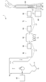
- FIG. 1 is a diagram showing a configuration of a thermal power generation system 1 to which an exhaust gas purification method according to this embodiment is applied.
- the thermal power generation system 1 includes a boiler 10, a pulverized coal machine 20, an exhaust path L1, an air preheater 30, a gas heater 40 as a heat recovery device, an electric dust collector 50, An induction ventilator 60, a desulfurization device 70, a gas heater 80 as a heater, a denitration device 90, and a chimney 100 are provided.
- the boiler 10 burns pulverized coal as fuel together with air.
- exhaust gas is generated by the combustion of pulverized coal.
- coal ash such as clinker ash and fly ash, produces
- the clinker ash generated in the boiler 10 is discharged to a clinker hopper 11 disposed below the boiler 10 and then conveyed to a coal ash recovery silo (not shown).
- the boiler 10 is formed in a substantially inverted U shape as a whole.
- the exhaust gas generated in the boiler 10 moves in an inverted U shape along the shape of the boiler 10.
- the temperature of the exhaust gas in the vicinity of the exhaust gas outlet of the boiler 10 is, for example, 300 to 400 ° C.
- the pulverized coal machine 20 pulverizes coal supplied from a coal bunker (not shown) to a fine particle size to form pulverized coal.
- the pulverized coal machine 20 preheats and dries the pulverized coal by mixing the pulverized coal and air.
- the pulverized coal formed in the pulverized coal machine 20 is supplied to the boiler 10 by blowing air.
- the upstream side of the exhaust passage L1 is connected to the boiler 10.
- the exhaust passage L1 is a passage through which exhaust gas generated in the boiler 10 flows.
- the air preheater 30 is disposed in the exhaust path L1.
- the air preheater 30 performs heat exchange between exhaust gas and combustion air fed from a not-shown push-type ventilator, and recovers heat from the exhaust gas.
- the combustion air is heated in the air preheater 30 and then supplied to the boiler 10.
- the gas heater 40 is disposed downstream of the air preheater 30 in the exhaust path L1.
- the exhaust gas recovered by the air preheater 30 is supplied to the gas heater 40.
- the gas heater 40 further recovers heat from the exhaust gas.
- the electric dust collector 50 is disposed on the downstream side of the gas heater 40 in the exhaust passage L1.
- the exhaust gas recovered by the gas heater 40 is supplied to the electric dust collector 50.
- the electric dust collector 50 is a device that collects coal ash (fly ash) in exhaust gas by applying a voltage to electrodes.
- the fly ash collected in the electric dust collector 50 is conveyed to a coal ash collection silo (not shown).
- the temperature of the exhaust gas in the electric dust collector 50 is, for example, 80 to 120 ° C.
- the induction fan 60 is disposed on the downstream side of the electric dust collector 50 in the exhaust path L1.
- the induction ventilator 60 takes in the exhaust gas from which fly ash has been removed in the electric dust collector 50 from the primary side and sends it out to the secondary side.
- the desulfurization device 70 is disposed on the downstream side of the induction fan 60 in the exhaust passage L1.
- the desulfurization apparatus 70 is supplied with the exhaust gas sent from the induction fan 60.
- the desulfurization device 70 removes sulfur oxide from the exhaust gas.
- the temperature of the exhaust gas in the desulfurizer 70 is, for example, 50 to 120 ° C.
- the gas heater 80 is disposed on the downstream side of the desulfurization device 70 in the exhaust passage L1.
- the gas heater 80 is supplied with exhaust gas from which sulfur oxides have been removed in the desulfurization apparatus 70.
- the gas heater 80 heats the exhaust gas.
- the gas heater 40 and the gas heater 80 are an exhaust gas flowing between the air preheater 30 and the electric dust collector 50 and an exhaust gas flowing between the desulfurization device 70 and a denitration device 90 described later in the exhaust passage L1. You may comprise as a gas gas heater which heat-exchanges between.
- the denitration device 90 is disposed downstream of the gas heater 80 in the exhaust path L1.
- the exhaust gas heated in the gas heater 80 is supplied to the denitration device 90.
- the denitration device 90 removes nitrogen oxides from the exhaust gas using a denitration catalyst.
- the temperature of the exhaust gas in the denitration apparatus 90 is 130 to 250 ° C.
- the chimney 100 is connected to the downstream side of the exhaust path L1. Exhaust gas from which nitrogen oxides have been removed by the denitration apparatus 90 is introduced into the chimney 100. Since the exhaust gas introduced into the chimney 100 is heated by the gas heater 80, it is effectively discharged from the upper part of the chimney 100 by the chimney effect. Further, when the exhaust gas is heated in the gas heater 80, it is possible to prevent water vapor from condensing above the chimney 100 and generating white smoke.
- the temperature of the exhaust gas near the exit of the chimney 100 is, for example, 110 ° C.
- the exhaust gas purification method according to the present embodiment includes a desulfurization step, a heating step, and a denitration step.
- the desulfurization step can be performed, for example, in the desulfurization apparatus 70 described above.
- sulfur oxides are removed from the exhaust gas.
- sulfur oxide can be removed from the exhaust gas by spraying a mixed liquid (limestone slurry) of limestone and water on the exhaust gas and absorbing the sulfur oxide contained in the exhaust gas into the mixed liquid.
- the heating step can be performed, for example, in the gas heater 80 described above.
- the exhaust gas is heated after the desulfurization step.
- the temperature of the exhaust gas can be adjusted to a temperature suitable for the reduction of nitrogen oxides in the denitration step described later.
- the denitration step can be performed, for example, in the denitration apparatus 90 described above.
- nitrogen oxides are removed from the exhaust gas after the heating process.
- nitrogen oxides contained in the exhaust gas at 130 to 250 ° C. are reduced using a denitration catalyst having a reducing agent and gold fine particles.
- the reducing agent used in the denitration process contains at least one of ammonia and urea.
- nitrogen oxides can be efficiently removed from the exhaust gas by reducing nitrogen oxides using a reducing agent to generate nitrogen and water. That is, in the denitration process, nitrogen oxides contained in the exhaust gas are reduced by a selective catalytic reduction method.
- ammonia is used as the reducing agent, ammonia in any state of ammonia gas, liquid ammonia, and aqueous ammonia solution may be used.
- ammonia gas is injected into the exhaust gas introduced into the denitration apparatus 90, and then the mixed gas is mixed with a honeycomb molded body to which a later-described denitration catalyst is fixed or an alumina carrying a later-described denitration catalyst.
- a fiber such as a fiber.
- the denitration catalyst used in the denitration process has fine gold particles.
- a denitration catalyst having gold fine particles can exhibit a high denitration effect even in a low temperature environment as compared with a conventional denitration catalyst such as a vanadium / titanium catalyst.
- the gold fine particles in the denitration catalyst are preferably gold nanoparticles or gold clusters having an average particle size of 50 nm or less (hereinafter, gold nanoparticles and gold clusters are collectively referred to as “gold nanoparticles”).
- gold nanoparticles When the average particle diameter of the gold fine particles is 50 nm or less, the denitration efficiency of the denitration catalyst is further improved.
- the gold fine particles preferably have an average particle size of 10 nm or less, and more preferably have an average particle size of 5 nm or less.
- the average particle size of the gold fine particles is determined by observing the metal fine particles with a scanning electron microscope (SEM) or a transmission electron microscope (TEM) and determining the particle size of an arbitrary number (for example, 20 to 100) of metal fine particles. And it can obtain
- SEM scanning electron microscope
- TEM transmission electron microscope
- the denitration catalyst is preferably a catalyst in which gold fine particles (gold nanoparticles) are dispersed or fixed on a carrier made of a metal oxide.
- the performance as a denitration catalyst is improved by dispersing or fixing the gold fine particles on a carrier made of a metal oxide.
- the metal oxide for dispersing or fixing the gold fine particles is at least one base metal oxide selected from the group consisting of zirconium oxide, cerium oxide, iron oxide, cobalt oxide, nickel oxide, copper oxide, manganese oxide, and zinc oxide. It is preferable.
- the performance of the gold fine particles as a denitration catalyst is improved. More preferably, at least one of zirconium oxide and cerium oxide is used as the metal oxide for dispersing or fixing the gold fine particles.
- a denitration catalyst in which gold fine particles (gold nanoparticles) are dispersed and fixed on a metal oxide surface can be produced by a conventionally known method of dispersing and fixing gold nanoparticles on a metal oxide surface.
- the method for dispersing and fixing the gold nanoparticles on the metal oxide surface include a precipitation method, a coprecipitation method, a precipitation reduction method, a gas phase grafting method, and a solid phase mixing method.
- a method of dispersing and fixing gold nanoparticles on the surface of the metal oxide by a precipitation method will be described.
- metal oxide particle powder is suspended in an aqueous solution of a gold compound.
- an alkali is added to the suspension to adjust the pH to a range of 7 to 10
- gold hydroxide is precipitated and precipitated on the base metal oxide surface.
- the suspension is stirred for 1 hour or longer (usually about 1 hour) while adjusting the concentration, pH and temperature of the gold compound and reducing agent, etc. Disperse and fix to.
- the gold hydroxide dispersed and immobilized on the surface of the metal oxide is washed with water, dried, and then calcined at 300 ° C. or higher in the presence of air to obtain a denitration catalyst.
- the metal oxide is appropriately selected according to the denitration performance required for the denitration catalyst.
- Examples of the gold compound used for dispersing and fixing gold fine particles (gold nanoparticles) on the surface of the metal oxide by the precipitation method include tetrachloroauric acid (HAuCl 4 ), tetrachloroaurate (for example, NaAuCl 4 ), gold cyanide (AuCN), potassium gold cyanide (K [Au (CN) 2 ]), diethylamine trichloride gold acid ((C 2 H 5 ) 2 NH ⁇ AuCl 3 ), ethylenediamine gold complex (for example, Chloride complexes (Au [C 2 H 4 (NH 2 ) 2 ] 2 Cl 3 )) and dimethylgold ⁇ -diketone derivative complexes (eg dimethylgold acetylacetonate ((CH 3 ) 2 Au [CH 3 COCHCOCH 3 ])) Or a gold salt or a gold complex.
- HuCl 4 tetrachloroauric acid
- AuCN gold cyanide
- the concentration of the gold compound aqueous solution is preferably from 0.1 to 10 mmol / L, more preferably from 0.5 to 2 mmol / L. If the concentration of the aqueous solution of the gold compound is less than 0.1 mmol / L, gold tends to be difficult to precipitate as a hydroxide on the metal oxide, and if it exceeds 10 mmol / L, the gold hydroxide precipitates in the solution. Tend to occur.
- the concentration of the gold compound dispersed / fixed in the metal oxide is adjusted to 0.01 to 50% by mass (the amount of gold fine particles relative to the mass of the metal oxide) by adjusting the concentration of the gold compound in the aqueous solution. Mass).
- alkali metal hydroxide, carbonate, alkaline earth metal hydroxide or carbonate, ammonia, urea, or the like can be used.
- the temperature of the suspension is preferably 0 to 90 ° C., and more preferably 30 to 70 ° C.
- the average particle diameter of the gold fine particles in the metal oxide prepared by dispersing and fixing gold fine particles on the surface is usually 1 to 50 nm.
- the average particle diameter of the gold fine particles is adjusted to the above range according to the required denitration performance.
- a denitration catalyst having a narrow particle distribution of gold fine particles (gold nanoparticles), that is, having a uniform particle diameter can be produced.
- the denitration catalyst can improve the denitration performance by dispersing and fixing gold fine particles having a narrow particle size distribution on the surface of the metal oxide.
- the exhaust gas purification method includes a denitration step of reducing nitrogen oxides contained in the exhaust gas at 130 to 250 ° C. by a selective catalytic reduction method using a denitration catalyst having a reducing agent and gold fine particles. It was supposed to be. Thereby, deterioration of the denitration catalyst due to the denitration catalyst being exposed to a high temperature environment can be suppressed. Further, the temperature of 130 to 250 ° C. is lower than the appropriate temperature for the reduction reaction using a conventional denitration catalyst such as a vanadium / titanium catalyst. However, if the denitration catalyst has gold fine particles, the exhaust gas is so low. Even at temperature, nitrogen oxides can be reduced efficiently. Therefore, according to the denitration catalyst according to the above embodiment, nitrogen oxides can be efficiently removed from the exhaust gas while suppressing deterioration of the denitration catalyst.
- the denitration catalyst is preferably a catalyst in which gold fine particles are dispersed or fixed on a carrier made of a metal oxide. Thereby, the denitration effect by the exhaust gas purification method according to the embodiment is improved.
- the carrier for dispersing or fixing the gold fine particles is at least one selected from the group consisting of zirconium oxide, cerium oxide, iron oxide, cobalt oxide, nickel oxide, copper oxide, manganese oxide, and zinc oxide.
- the base metal oxide is preferably used. Thereby, the denitration effect by the exhaust gas purification method according to the embodiment is further improved.
- the gold fine particles of the denitration catalyst are preferably gold nanoparticles or gold clusters having an average particle diameter of 50 nm or less.
- the reducing agent includes at least one of ammonia and urea.
- the exhaust gas purification method further includes a desulfurization step of removing sulfur oxides from the exhaust gas before the denitration step.
- the exhaust gas purification method further includes a heating step for heating the exhaust gas between the desulfurization method and the denitration step.
- a heating step for heating the exhaust gas between the desulfurization method and the denitration step.
- the exhaust gas from which nitrogen oxides are removed by the exhaust gas purification method according to the above embodiment is an exhaust gas generated by burning coal.
- the concentration of sulfur oxides and nitrogen oxides in the exhaust gas tends to increase, so that the denitration catalyst easily deteriorates.
- the exhaust gas purification method according to the above-described embodiment even when coal is burned, nitrogen oxides can be efficiently removed from exhaust gas while suppressing deterioration of the denitration catalyst.
- the present invention is not limited to the above-described embodiment, and modifications, improvements, etc. within a scope that can achieve the object of the present invention are included in the present invention.
- the exhaust gas purification method which concerns on this invention was applied to the thermal power generation system 1, this invention is not limited to this.
- the denitration catalyst according to the present invention may be applied to an exhaust gas treatment facility in a garbage incinerator or the like.
- the exhaust gas purification method according to the present invention may not include the desulfurization step and the heating step.
- each denitration catalyst used in Examples and Comparative Examples was prepared as follows.
- Example 1 0.1M sodium hydroxide was added to a suspension obtained by adding cerium oxide to a 1.0 mM chloroauric acid aqueous solution until the pH reached 7.0. The suspension whose pH was adjusted to 7.0 was stirred for 1 hour, repeatedly washed with pure water, and then filtered to obtain a residue. The obtained filtrate was dried at 120 ° C. overnight and calcined at 300 ° C. for 4 hours in the presence of air. The solid obtained after calcination (catalyst having gold nanoparticles fixed to cerium oxide) was used as the denitration catalyst of Example 1. In the denitration catalyst of Example 1, the average particle diameter of the gold nanoparticles was 50 nm or less. [Comparative Example 1] The cerium oxide used in the preparation of the desulfurization catalyst of Example 1 was used as the denitration catalyst of Comparative Example 1.
- Example 2 To a suspension obtained by adding zirconium oxide to a 1.0 mM chloroauric acid aqueous solution, 0.1 M sodium hydroxide was added until the pH reached 7.0. The suspension whose pH was adjusted to 7.0 was stirred for 1 hour, repeatedly washed with pure water, and then filtered to obtain a residue. The obtained filtrate was dried at 120 ° C. overnight and calcined at 300 ° C. for 4 hours in the presence of air. The solid (catalyst in which gold nanoparticles were fixed to zirconium oxide) obtained after calcination was used as the denitration catalyst of Example 2. In the denitration catalyst of Example 2, the average particle size of the gold nanoparticles was 50 nm or less. [Comparative Example 2] The zirconium oxide used in the preparation of the desulfurization catalyst of Example 1 was used as the denitration catalyst of Comparative Example 2.
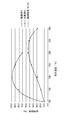
- FIG. 1 A graph showing the relationship between the reaction temperature and the denitration efficiency for the denitration catalysts of Example 1 and Comparative Example 1 is shown in FIG. Moreover, the graph which showed the relationship between reaction temperature and the denitration efficiency about the denitration catalyst of Example 2 and Comparative Example 2 was shown in FIG. Note that conventionally used vanadium / titanium catalyst (V 2 O 5 / TiO 2 ), the measuring method described above (reaction temperature: 370 ° C.) denitration efficiency measured by is 79.1%. 2 and 3, the denitration efficiency of 79.1% is indicated by a two-dot chain line.
- V 2 O 5 / TiO 2 vanadium / titanium catalyst
- FIG. 4 is a graph showing the results of measuring the denitration efficiency of various metal oxides and denitration catalysts in which gold nanoparticles are supported on various metal oxides under a reaction temperature of 200 ° C.
- the denitration catalyst in which gold nanoparticles are supported on various metal oxides can be prepared by the same method as the denitration catalyst of Example 1 and Example 2 above. The denitration efficiency was measured by the above method.
- the denitration catalyst of Example 1 has higher denitration efficiency in the low temperature region than the denitration catalyst of Comparative Example 1.
- the denitration efficiency of the denitration catalyst of Example 1 under the condition of 130 to 250 ° C. is equal to or greater than the denitration efficiency of the vanadium / titanium catalyst used conventionally under the condition of 370 ° C. (temperature near the boiler outlet). It turns out that. From these results, it was revealed that a catalyst in which gold nanoparticles were fixed to cerium oxide was a particularly excellent denitration catalyst in a low temperature region.
- FIG. 4 is a graph showing the results of measuring the denitration efficiency of various metal oxides and denitration catalysts in which gold nanoparticles are supported on various metal oxides under a reaction temperature of 200 ° C.
- the denitration catalyst in which gold nanoparticles are supported on various metal oxides can be prepared by the same method as the denitration catalyst of Example 1 and Example 2 above. The denitration efficiency was measured by the above method.
- Example 2 From the results of Example 2 and Comparative Example 2 shown in FIG. 3, it was found that the denitration catalyst of Example 2 has higher denitration efficiency in the low temperature region than the denitration catalyst of Comparative Example 2.
- the denitration efficiency of the denitration catalyst of Example 1 under the condition of 130 to 300 ° C. is equal to or higher than the denitration efficiency of the vanadium / titanium catalyst used conventionally at 370 ° C. From these results, it has been clarified that a catalyst in which gold nanoparticles are fixed to zirconium oxide is also a particularly excellent denitration catalyst in a low temperature region.
- the denitration catalyst in which gold nanoparticles are supported on the metal oxide has lower denitration efficiency at a low temperature (200 ° C.) than the metal oxide. I found it expensive. From these results, it was confirmed that the metal oxide improves the denitration efficiency at a low temperature by supporting the gold nanoparticles.
- nitrogen oxides contained in the exhaust gas at 130 to 250 ° C. are reduced by selective catalytic reduction using a denitration catalyst having a reducing agent and gold fine particles, nitrogen oxides are removed from the exhaust gas with high efficiency. It is recognized that it can be done.
Landscapes
- Chemical & Material Sciences (AREA)
- Engineering & Computer Science (AREA)
- Chemical Kinetics & Catalysis (AREA)
- Materials Engineering (AREA)
- Organic Chemistry (AREA)
- Environmental & Geological Engineering (AREA)
- Health & Medical Sciences (AREA)
- Biomedical Technology (AREA)
- Analytical Chemistry (AREA)
- General Chemical & Material Sciences (AREA)
- Oil, Petroleum & Natural Gas (AREA)
- Exhaust Gas Treatment By Means Of Catalyst (AREA)
- Catalysts (AREA)
Abstract
脱硝触媒の劣化を抑えつつ、効率的に排ガスから窒素酸化物を除去することができる排ガス浄化方法を提供する。 燃料が燃焼することによって発生する排ガスを浄化する排ガス浄化方法であって、130~250℃の前記排ガスの含有する窒素酸化物を、還元剤及び金微粒子を有する脱硝触媒を用いて選択接触還元法によって還元することで、前記排ガスから窒素酸化物を除去する脱硝工程を有する。また、前記脱硝触媒は、金属酸化物からなる担体上に金微粒子を分散又は固定させた触媒であることが好ましい。
Description
本発明は、排ガス浄化方法に関する。より詳しくは、本発明は、燃料が燃焼することによって発生する排ガスを浄化する排ガス浄化方法に関する。
従来、火力発電所では、ボイラにおいて石炭等の燃料を燃焼させることによって得られる熱エネルギーを、タービンによって電気エネルギーに変換している。また、火力発電所のボイラにおいて燃料を燃焼させると、硫黄酸化物や窒素酸化物を含む排ガスが発生する。
ボイラにおいて発生する排ガスは、排気路を通してボイラから外部に排出される。ボイラから外部に排出される排ガスからは、環境面への配慮により、脱硫装置及び脱硝装置によってそれぞれ硫黄酸化物及び窒素酸化物が除去されている。
ところで、排ガスから窒素酸化物を除去する脱硫装置には、一般的にバナジウム/チタン触媒(V2O5/TiO2)等の脱硝触媒が用いられている。そして、バナジウム/チタン触媒は、高温(例えば、約370℃)環境下において高い触媒活性が発揮されることから、火力発電所において脱硝装置は、ボイラ内の排ガスの出口の近傍や、排気路の上流側に配置される(例えば、特許文献1等参照)。
一方で、ボイラ内の排ガスの出口の近傍や、排気路の上流側は、上記のように高温であることから、脱硝触媒の劣化が進行しやすい環境でもある。脱硝触媒の劣化が急速に進行すると、脱硝触媒の交換頻度が高くなることから、火力発電所においては、稼働のコストが高くなってしまう傾向にある。このような問題に対して、脱硝装置に供給される排ガスの温度を低く抑えた場合には、脱硝触媒の活性が低くなることで、脱硝効率が低下してしまう。
本発明は、上記課題に鑑みてなされたものであり、脱硝触媒の劣化を抑えつつ、効率的に排ガスから窒素酸化物を除去することができる排ガス浄化方法を提供することを目的とする。
本発明は、燃料が燃焼することによって発生する排ガスを浄化する排ガス浄化方法であって、130~250℃の前記排ガスの含有する窒素酸化物を、還元剤及び金微粒子を有する脱硝触媒を用いて選択接触還元法によって還元することで、前記排ガスから窒素酸化物を除去する脱硝工程を有する排ガス浄化方法に関する。
また、前記脱硝触媒は、金属酸化物からなる担体上に金微粒子を分散又は固定させた触媒であることが好ましい。
また、前記金属酸化物は、酸化ジルコニウム、酸化セリウム、酸化鉄、酸化チタン、酸化アルミニウム、酸化ケイ素、酸化コバルト、酸化ニッケル、酸化銅、酸化マンガン及び酸化亜鉛からなる群より選択される少なくとも一種の金属酸化物であることが好ましい。
また、前記金微粒子は、平均粒子径が50nm以下の金ナノ粒子又は金クラスターであることが好ましい。
また、前記還元剤は、アンモニア及び尿素の少なくとも一方を含むことが好ましい。
また、前記排ガス浄化方法は、前記脱硝工程の前に、前記排ガスから硫黄酸化物を除去する脱硫工程を更に有することが好ましい。
また、前記排ガス浄化方法は、前記脱硫方法と前記脱硝工程との間において、前記排ガスを加熱する加熱工程を更に有することが好ましい。
また、前記燃料は、石炭であることが好ましい。
脱硝触媒の劣化を抑えつつ、効率的に排ガスから窒素酸化物を除去することができる排ガス浄化方法を提供できる。
以下、本発明の一実施形態について図面を参照しながら説明する。
図1は、本実施形態に係る排ガス浄化方法を適用した火力発電システム1の構成を示す図である。図1に示すように、火力発電システム1は、ボイラ10と、微粉炭機20と、排気路L1と、空気予熱器30と、熱回収器としてのガスヒータ40と、電気集塵装置50と、誘引通風機60と、脱硫装置70と、加熱器としてのガスヒータ80と、脱硝装置90と、煙突100と、を備える。
図1は、本実施形態に係る排ガス浄化方法を適用した火力発電システム1の構成を示す図である。図1に示すように、火力発電システム1は、ボイラ10と、微粉炭機20と、排気路L1と、空気予熱器30と、熱回収器としてのガスヒータ40と、電気集塵装置50と、誘引通風機60と、脱硫装置70と、加熱器としてのガスヒータ80と、脱硝装置90と、煙突100と、を備える。
ボイラ10は、燃料としての微粉炭を空気とともに燃焼させる。ボイラ10において、微粉炭が燃焼することにより排ガスが発生する。なお、微粉炭が燃焼することによって、クリンカアッシュ及びフライアッシュ等の石炭灰が生成する。ボイラ10において生成するクリンカアッシュは、ボイラ10の下方に配置されるクリンカホッパ11に排出されてから、図示しない石炭灰回収サイロに搬送される。
ボイラ10は、全体として略逆U字状に形成される。ボイラ10において生成する排ガスは、ボイラ10の形状に沿って逆U字状に移動する。ボイラ10の排ガスの出口付近における排ガスの温度は、例えば300~400℃である。
微粉炭機20は、図示しない石炭バンカから供給される石炭を、微細な粒度に粉砕して微粉炭を形成する。微粉炭機20は、微粉炭と空気とを混合することにより、微粉炭を予熱及び乾燥させる。微粉炭機20において形成された微粉炭は、エアーが吹きつけられることにより、ボイラ10に供給される。
排気路L1は、上流側がボイラ10に接続される。排気路L1は、ボイラ10において発生する排ガスが流通する流路である。
空気予熱器30は、排気路L1に配置される。空気予熱器30は、排ガスと図示しない押込式通風機から送り込まれる燃焼用の空気との間で熱交換を行い、排ガスから熱回収する。燃焼用の空気は、空気予熱器30において加熱されてからボイラ10に供給される。
ガスヒータ40は、排気路L1における空気予熱器30の下流側に配置される。ガスヒータ40には、空気予熱器30において熱回収された排ガスが供給される。ガスヒータ40は、排ガスから更に熱回収する。
電気集塵装置50は、排気路L1におけるガスヒータ40の下流側に配置される。電気集塵装置50には、ガスヒータ40において熱回収された排ガスが供給される。電気集塵装置50は、電極に電圧を印加することによって排ガス中の石炭灰(フライアッシュ)を収集する装置である。電気集塵装置50において捕集されるフライアッシュは、図示しない石炭灰回収サイロに搬送される。電気集塵装置50における排ガスの温度は、例えば80~120℃である。
誘引通風機60は、排気路L1における電気集塵装置50の下流側に配置される。誘引通風機60は、電気集塵装置50においてフライアッシュを除去した排ガスを、一次側から取り込んで二次側に送り出す。
脱硫装置70は、排気路L1における誘引通風機60の下流側に配置される。脱硫装置70には、誘引通風機60から送り出された排ガスが供給される。脱硫装置70は、排ガスから硫黄酸化物を除去する。脱硫装置70における排ガスの温度は、例えば50~120℃である。
ガスヒータ80は、排気路L1における脱硫装置70の下流側に配置される。ガスヒータ80には、脱硫装置70において硫黄酸化物が除去された排ガスが供給される。ガスヒータ80は、排ガスを加熱する。ガスヒータ40及びガスヒータ80は、排気路L1における、空気予熱器30と電気集塵装置50との間を流通する排ガスと、脱硫装置70と後述する脱硝装置90との間を流通する排ガスと、の間で熱交換を行うガスガスヒータとして構成してもよい。
脱硝装置90は、排気路L1におけるガスヒータ80の下流側に配置される。脱硝装置90には、ガスヒータ80において加熱された排ガスが供給される。脱硝装置90は、脱硝触媒によって排ガスから窒素酸化物を除去する。脱硝装置90における排ガスの温度は、130~250℃である。
煙突100は、排気路L1の下流側が接続される。煙突100には、脱硝装置90において窒素酸化物を除去した排ガスが導入される。煙突100に導入された排ガスは、ガスヒータ80によって加熱されていることから、煙突効果によって煙突100の上部から効果的に排出される。また、ガスヒータ80において排ガスが加熱されることで、煙突100の上方において水蒸気が凝縮して白煙が生じるのを防ぐことができる。煙突100の出口付近における排ガスの温度は、例えば110℃である。
続いて、本実施形態に係る排ガス浄化方法について説明する。
本実施形態に係る排ガス浄化方法は、脱硫工程と、加熱工程と、脱硝工程と、を備える。
本実施形態に係る排ガス浄化方法は、脱硫工程と、加熱工程と、脱硝工程と、を備える。
脱硫工程は、例えば上記の脱硫装置70において行うことができる。脱硫工程では、排ガスから硫黄酸化物を除去する。脱硫工程においては、例えば、排ガスに石灰石と水との混合液(石灰石スラリー)を吹き付けて、排ガスに含まれる硫黄酸化物を混合液に吸収させることで、排ガスから硫黄酸化物を除去できる。
加熱工程は、例えば上記のガスヒータ80において行うことができる。加熱工程では、脱硫工程の後に、排ガスを加熱する。加熱工程においては、後述する脱硝工程における窒素酸化物の還元に適した温度に、排ガスの温度を調整することができる。
脱硝工程は、例えば上記の脱硝装置90において行うことができる。脱硝工程では、加熱工程の後に、排ガスから窒素酸化物を除去する。脱硝工程では、130~250℃の排ガスの含有する窒素酸化物を、還元剤及び金微粒子を有する脱硝触媒を用いて還元する。
脱硝工程において用いられる還元剤は、アンモニア及び尿素の少なくとも一方を含む。脱硝工程においては、還元剤を用いて窒素酸化物を還元し、窒素及び水を生成することで、排ガスから効率的に窒素酸化物を除去できる。つまり、脱硝工程では、選択接触還元法によって排ガスの含有する窒素酸化物を還元する。なお、還元剤としてアンモニアを用いる場合、アンモニアガス、液体アンモニア及びアンモニア水溶液のいずれの状態のアンモニアを用いてもよい。
脱硝工程においては、例えば脱硝装置90に導入された排ガスに対してアンモニアガスを注入してから、その混合ガスを、後述の脱硝触媒を固定したハニカム成形体や後述の脱硝触媒を担持させたアルミナ繊維等の繊維に接触させる。
脱硝工程において用いられる脱硝触媒は、金微粒子を有する。金微粒子を有する脱硝触媒は、従来用いられているバナジウム/チタン触媒等の脱硝触媒に比べて、低温環境下でも高い脱硝効果を発揮できる。
脱硝触媒における金微粒子は、平均粒子径が50nm以下の金ナノ粒子又は金クラスター(以下、金ナノ粒子及び金クラスターをまとめて「金ナノ粒子」と言う)であることが好ましい。金微粒子の平均粒子径が50nm以下であることによって、脱硝触媒の脱硝効率がより向上する。金微粒子は、平均粒子径が10nm以下であることがより好ましく、平均粒径が5nm以下であることが更に好ましい。
金微粒子の平均粒子径は、走査型電子顕微鏡(SEM)又は透過型電子顕微鏡(TEM)によって金属微粒子を観察して、任意の数(例えば、20~100個)の金属微粒子の粒子径を決定し、これらの粒子径を平均することにより求めることができる。
金微粒子の平均粒子径は、走査型電子顕微鏡(SEM)又は透過型電子顕微鏡(TEM)によって金属微粒子を観察して、任意の数(例えば、20~100個)の金属微粒子の粒子径を決定し、これらの粒子径を平均することにより求めることができる。
脱硝触媒は、金属酸化物からなる担体上に金微粒子(金ナノ粒子)を分散又は固定させた触媒であることが好ましい。金微粒子は、金属酸化物からなる担体上に分散又は固定させることで、脱硝触媒としての性能が向上する。金微粒子を分散又は固定させる金属酸化物は、酸化ジルコニウム、酸化セリウム、酸化鉄、酸化コバルト、酸化ニッケル、酸化銅、酸化マンガン及び酸化亜鉛からなる群より選択される少なくとも一種の卑金属酸化物であることが好ましい。これらから選択される一種の卑金属酸化物又は二種以上を用いた卑金属複合酸化物を担体とすることで、金微粒子の脱硝触媒としての性能が向上する。金微粒子を分散又は固定させる金属酸化物としては、酸化ジルコニウム及び酸化セリウムの少なくとも一方を用いることがより好ましい。
金属酸化物表面に金微粒子(金ナノ粒子)を分散・固定させた脱硝触媒は、従来知られた金属酸化物表面に金ナノ粒子を分散・固定させる方法によって作製できる。金属酸化物表面に金ナノ粒子を分散・固定させる方法としては、析出沈殿法、共沈法、析出還元法、気相グラフティング及び固相混合法等が例示される。以下、析出沈殿法により金属酸化物表面に金ナノ粒子を分散・固定させる方法を示す。
析出沈殿法では、金属酸化物粒子の粉末を金化合物の水溶液に懸濁させる。続いて、その懸濁液にアルカリを加えて、pHを7~10の範囲に調整し、金水酸化物を卑金属酸化物表面上に析出・沈殿させる。続いて、この懸濁液を、金化合物及び還元剤等の濃度、pH及び温度を調整しながら、1時間以上(通常は1時間程度)撹拌し続けることによって、金水酸化物を金属酸化物表面に分散・固定化する。続いて、金属酸化物表面に分散・固定化した金水酸化物を水洗した後に乾燥し、更に空気存在下300℃以上で焼成することによって、脱硝触媒が得られる。このとき、金属酸化物は、脱硝触媒に要求される脱硝性能に応じて適宜選択される。
析出沈殿法によって、金属酸化物表面に金微粒子(金ナノ粒子)を分散・固定させる際に用いられる金化合物としては、例えば、四塩化金酸(HAuCl4)、四塩化金酸塩(例えば、NaAuCl4)、シアン化金(AuCN)、シアン化金カリウム(K[Au(CN)2])、三塩化ジエチルアミン金酸((C2H5)2NH・AuCl3)、エチレンジアミン金錯体(例えば、塩化物錯体(Au[C2H4(NH2)2]2Cl3))及びジメチル金β‐ジケトン誘導体錯体(例えば、ジメチル金アセチルアセトナート((CH3)2Au[CH3COCHCOCH3]))等の金の塩や金錯体が挙げられる。金属酸化物表面に金微粒子を分散・固定させる際には、上記の金化合物の他にも、水や有機溶媒に溶解可能なあらゆる金の塩や金錯体を用いることができる。
析出沈殿法における、金化合物の水溶液の濃度(金元素換算の濃度)は、0.1~10mmol/Lが好ましく、0.5~2mmol/Lがより好ましい。金化合物の水溶液の濃度が、0.1mmol/L未満だと金が金属酸化物上に水酸化物として析出し難くなる傾向にあり、10mmol/Lを超えると溶液中にも金水酸化物の沈殿が生じてしまう傾向にある。
なお、析出沈殿法では、金化合物の水溶液における濃度を調整することで、金属酸化物に分散・固定する金の担持量を、0.01~50質量%(金属酸化物の質量に対する金微粒子の質量)の範囲に調整することができる。
なお、析出沈殿法では、金化合物の水溶液における濃度を調整することで、金属酸化物に分散・固定する金の担持量を、0.01~50質量%(金属酸化物の質量に対する金微粒子の質量)の範囲に調整することができる。
析出沈殿法における、pH調整用のアルカリとしては、アルカリ金属の水酸化物、炭酸塩、アルカリ土類金属の水酸化物又は炭酸塩、アンモニア及び尿素等を用いることができる。
析出沈殿法における、懸濁液の温度は、0~90℃であることが好ましく、30~70℃であることがより好ましい。
析出沈殿法における、懸濁液の温度は、0~90℃であることが好ましく、30~70℃であることがより好ましい。
このようにして調製される、表面に金微粒子を分散・固定させた金属酸化物における、金微粒子の平均粒子径は、通常1~50nmである。金微粒子の平均粒子径は、求められる脱硝性能に応じて、上記の範囲に調整される。また、析出沈殿法によれば、金微粒子(金ナノ粒子)の粒子分布が狭い、つまり粒子径の揃った脱硝触媒を製造することができる。脱硝触媒は、粒子径分布の狭い金微粒子を金属酸化物の表面に分散・固定させることによって、脱硝性能を向上させることができる。
上記実施形態に係る排ガス浄化方法によれば、以下の効果が奏される。
(1)上記実施形態では、排ガス浄化方法が、130~250℃の排ガスの含有する窒素酸化物を、還元剤及び金微粒子を有する脱硝触媒を用いて選択接触還元法によって還元する脱硝工程を有するものとした。
これにより、脱硝触媒が高温環境に晒されることによる脱硝触媒の劣化を抑えることができる。また、130~250℃は、従来用いられているバナジウム/チタン触媒等の脱硝触媒による還元反応の適温よりも低い温度であるが、金微粒子を有する脱硝触媒であれば、排ガスがこのような低い温度であっても効率的に窒素酸化物を還元できる。従って、上記実施形態に係る脱硝触媒によれば、脱硝触媒の劣化を抑えつつ、効率的に排ガスから窒素酸化物を除去することができる。
(1)上記実施形態では、排ガス浄化方法が、130~250℃の排ガスの含有する窒素酸化物を、還元剤及び金微粒子を有する脱硝触媒を用いて選択接触還元法によって還元する脱硝工程を有するものとした。
これにより、脱硝触媒が高温環境に晒されることによる脱硝触媒の劣化を抑えることができる。また、130~250℃は、従来用いられているバナジウム/チタン触媒等の脱硝触媒による還元反応の適温よりも低い温度であるが、金微粒子を有する脱硝触媒であれば、排ガスがこのような低い温度であっても効率的に窒素酸化物を還元できる。従って、上記実施形態に係る脱硝触媒によれば、脱硝触媒の劣化を抑えつつ、効率的に排ガスから窒素酸化物を除去することができる。
(2)上記のように、脱硝触媒は、金属酸化物からなる担体上に金微粒子を分散又は固定させた触媒とするのが好ましい。
これにより、上記実施形態に係る排ガス浄化方法による脱硝効果が向上する。
これにより、上記実施形態に係る排ガス浄化方法による脱硝効果が向上する。
(3)上記のように、金微粒子を分散又は固定させる担体は、酸化ジルコニウム、酸化セリウム、酸化鉄、酸化コバルト、酸化ニッケル、酸化銅、酸化マンガン及び酸化亜鉛からなる群より選択される少なくとも一種の卑金属酸化物とするのが好ましい。
これにより、上記実施形態に係る排ガス浄化方法による脱硝効果がより向上する。
これにより、上記実施形態に係る排ガス浄化方法による脱硝効果がより向上する。
(4)上記のように、脱硝触媒の有する金微粒子は、平均粒子径が50nm以下の金ナノ粒子又は金クラスターとするのが好ましい。
これにより、上記実施形態に係る排ガス浄化方法による脱硝効果が向上する。
これにより、上記実施形態に係る排ガス浄化方法による脱硝効果が向上する。
(5)上記実施形態に係る排ガス浄化方法では、還元剤が、アンモニア及び尿素の少なくとも一方を含むものとした。
これにより、脱硝工程において、排ガスの含有する窒素酸化物を高い効率で選択的に還元することができる。
これにより、脱硝工程において、排ガスの含有する窒素酸化物を高い効率で選択的に還元することができる。
(6)上記実施形態では、排ガス浄化方法が、脱硝工程の前に、排ガスから硫黄酸化物を除去する脱硫工程を更に有するものとした。
これにより、脱硝工程の前に排ガスから硫黄酸化物が除去されるので、脱硝触媒の劣化をより抑えることができる。
これにより、脱硝工程の前に排ガスから硫黄酸化物が除去されるので、脱硝触媒の劣化をより抑えることができる。
(7)上記実施形態では、排ガス浄化方法が、脱硫方法と脱硝工程との間において、排ガスを加熱する加熱工程を更に有する
これにより、脱硫工程の後に排ガスの温度が下がり過ぎた場合でも、脱硝工程における窒素酸化物の還元に適した温度に、排ガスの温度を調整することができる。
これにより、脱硫工程の後に排ガスの温度が下がり過ぎた場合でも、脱硝工程における窒素酸化物の還元に適した温度に、排ガスの温度を調整することができる。
(8)上記実施形態に係る排ガス浄化方法によって窒素酸化物を除去する排ガスを、石炭が燃焼することによって発生する排ガスとした。
石炭を燃焼させると、排ガスにおける硫黄酸化物及び窒素酸化物の濃度が高くなる傾向にあることから、脱硝触媒の劣化が進行しやすくなる。上記実施形態に係る排ガス浄化方法よれば、石炭を燃焼させた場合であっても、脱硝触媒の劣化を抑えつつ、効率的に排ガスから窒素酸化物を除去することができる。
石炭を燃焼させると、排ガスにおける硫黄酸化物及び窒素酸化物の濃度が高くなる傾向にあることから、脱硝触媒の劣化が進行しやすくなる。上記実施形態に係る排ガス浄化方法よれば、石炭を燃焼させた場合であっても、脱硝触媒の劣化を抑えつつ、効率的に排ガスから窒素酸化物を除去することができる。
なお、本発明は上記実施形態に限定されるものではなく、本発明の目的を達成できる範囲での変形、改良等は本発明に含まれる。
上記実施形態では、火力発電システム1に本発明に係る排ガス浄化方法を適用したが、本発明はこれに限定されない。例えば、本発明に係る脱硝触媒は、ゴミ焼却場等における排ガス処理設備に適用してもよい。また、本発明に係る排ガス浄化方法は、上記の脱硫工程及び加熱工程を有していなくてもよい。
上記実施形態では、火力発電システム1に本発明に係る排ガス浄化方法を適用したが、本発明はこれに限定されない。例えば、本発明に係る脱硝触媒は、ゴミ焼却場等における排ガス処理設備に適用してもよい。また、本発明に係る排ガス浄化方法は、上記の脱硫工程及び加熱工程を有していなくてもよい。
以下、本発明を実施例によって具体的に説明する。なお、本発明は実施例によって限定されるものではない。まず、実施例及び比較例において用いられる各脱硝触媒を以下のように調製した。
[実施例1]
1.0mMの塩化金酸水溶液に酸化セリウムを加えて得られた懸濁液に、pHが7.0になるまで0.1M水酸化ナトリウムを加えた。pHを7.0に調整した懸濁液を1時間撹拌し、純水での洗浄を繰り返した後にろ過をしてろ物を得た。得られたろ物を120℃で一晩乾燥させて、空気存在下300℃で4時間焼成した。焼成後に得られた固体(金ナノ粒子を酸化セリウムに固定させた触媒)を実施例1の脱硝触媒とした。実施例1の脱硝触媒における、金ナノ粒子の平均粒子径は50nm以下であった。
[比較例1]
実施例1の脱硫触媒の調製において用いた酸化セリウムを比較例1の脱硝触媒とした。
1.0mMの塩化金酸水溶液に酸化セリウムを加えて得られた懸濁液に、pHが7.0になるまで0.1M水酸化ナトリウムを加えた。pHを7.0に調整した懸濁液を1時間撹拌し、純水での洗浄を繰り返した後にろ過をしてろ物を得た。得られたろ物を120℃で一晩乾燥させて、空気存在下300℃で4時間焼成した。焼成後に得られた固体(金ナノ粒子を酸化セリウムに固定させた触媒)を実施例1の脱硝触媒とした。実施例1の脱硝触媒における、金ナノ粒子の平均粒子径は50nm以下であった。
[比較例1]
実施例1の脱硫触媒の調製において用いた酸化セリウムを比較例1の脱硝触媒とした。
[実施例2]
1.0mMの塩化金酸水溶液に酸化ジルコニウムを加えて得られた懸濁液に、pHが7.0になるまで0.1M水酸化ナトリウムを加えた。pHを7.0に調整した懸濁液を1時間撹拌し、純水での洗浄を繰り返した後にろ過をしてろ物を得た。得られたろ物を120℃で一晩乾燥させて、空気存在下300℃で4時間焼成した。焼成後に得られた固体(金ナノ粒子を酸化ジルコニウムに固定させた触媒)を実施例2の脱硝触媒とした。実施例2の脱硝触媒における、金ナノ粒子の平均粒子径は50nm以下であった。
[比較例2]
実施例1の脱硫触媒の調製において用いた酸化ジルコニウムを比較例2の脱硝触媒とした。
1.0mMの塩化金酸水溶液に酸化ジルコニウムを加えて得られた懸濁液に、pHが7.0になるまで0.1M水酸化ナトリウムを加えた。pHを7.0に調整した懸濁液を1時間撹拌し、純水での洗浄を繰り返した後にろ過をしてろ物を得た。得られたろ物を120℃で一晩乾燥させて、空気存在下300℃で4時間焼成した。焼成後に得られた固体(金ナノ粒子を酸化ジルコニウムに固定させた触媒)を実施例2の脱硝触媒とした。実施例2の脱硝触媒における、金ナノ粒子の平均粒子径は50nm以下であった。
[比較例2]
実施例1の脱硫触媒の調製において用いた酸化ジルコニウムを比較例2の脱硝触媒とした。
以上のようにして得られた実施例及び比較例の各脱硝触媒について、以下の方法により脱硝効率を測定した。
<脱硝効率の測定>
各脱硝触媒0.75gを円筒形の反応容器に詰めた。そして、反応ガス(一酸化窒素440ppm、アンモニア440ppm及び酸素4mol/Lを含むアルゴン)を、500mL/分の流速で、所定の温度のもと、脱硝触媒を詰めた反応容器の一端側から他端側へ通過させた。反応容器を通過した後の一酸化窒素の濃度をポータブル燃焼排ガス分析器testo350XL(株式会社テストー製)にて測定し、測定された濃度(Xppm)及び反応容器を通過する前の一酸化窒素の濃度から、下記式(1)に基いて脱硝効率を算出した。
[数1]
脱硝効率(%)=(440-X)/440 ・・・(1)
各脱硝触媒0.75gを円筒形の反応容器に詰めた。そして、反応ガス(一酸化窒素440ppm、アンモニア440ppm及び酸素4mol/Lを含むアルゴン)を、500mL/分の流速で、所定の温度のもと、脱硝触媒を詰めた反応容器の一端側から他端側へ通過させた。反応容器を通過した後の一酸化窒素の濃度をポータブル燃焼排ガス分析器testo350XL(株式会社テストー製)にて測定し、測定された濃度(Xppm)及び反応容器を通過する前の一酸化窒素の濃度から、下記式(1)に基いて脱硝効率を算出した。
[数1]
脱硝効率(%)=(440-X)/440 ・・・(1)
実施例1及び比較例1の脱硝触媒について、反応温度と脱硝効率との関係を示したグラフを図2に示した。また、実施例2及び比較例2の脱硝触媒について、反応温度と脱硝効率との関係を示したグラフを図3に示した。なお、従来用いられているバナジウム/チタン触媒(V2O5/TiO2)について、上記の測定方法(反応温度:370℃)によって測定した脱硝効率は、79.1%である。図2及び図3において、79.1%の脱硝効率を二点鎖線で示した。
なお、図4は、各種金属酸化物及び各種金属酸化物に金ナノ粒子を担持させた脱硝触媒について、反応温度200℃の条件下で脱硝効率を測定した結果を示したグラフである。各種金属酸化物に金ナノ粒子を担持させた脱硝触媒については、上記の実施例1及び実施例2の脱硝触媒と同様の方法によって調製できる。また、脱硝効率の測定は上記の方法で行った。
図2に示した実施例1及び比較例1の結果から、実施例1の脱硝触媒は比較例1の脱硝触媒よりも、低温領域における脱硝効率が高いことが分かった。特に130~250℃の条件下における、実施例1の脱硝触媒の脱硝効率は、従来用いられているバナジウム/チタン触媒の370℃の条件下(ボイラの出口付近の温度)における脱硝効率と同等以上であることが分かった。これらの結果から、金ナノ粒子を酸化セリウムに固定させた触媒が、低温領域において特に優れた脱硝触媒であることが明らかになった。
なお、図4は、各種金属酸化物及び各種金属酸化物に金ナノ粒子を担持させた脱硝触媒について、反応温度200℃の条件下で脱硝効率を測定した結果を示したグラフである。各種金属酸化物に金ナノ粒子を担持させた脱硝触媒については、上記の実施例1及び実施例2の脱硝触媒と同様の方法によって調製できる。また、脱硝効率の測定は上記の方法で行った。
図3に示した実施例2及び比較例2の結果から、実施例2の脱硝触媒は比較例2の脱硝触媒よりも、低温領域における脱硝効率が高いことが分かった。特に130~300℃の条件下における、実施例1の脱硝触媒の脱硝効率は、従来用いられているバナジウム/チタン触媒の370℃の条件下における脱硝効率と同等以上であることが分かった。これらの結果から、金ナノ粒子を酸化ジルコニウムに固定させた触媒も、低温領域において特に優れた脱硝触媒であることが明らかになった。
また、図4に示した結果から、全ての金属酸化物において、金属酸化物よりも、その金属酸化物に金ナノ粒子を担持させた脱硝触媒の方が、低温(200℃)における脱硝効率が高いことが分かった。これらの結果から、金属酸化物は、金ナノ粒子を担持させることによって、低温における脱硝効率が向上することが確認された。
このように、130~250℃の前記排ガスの含有する窒素酸化物を、還元剤及び金微粒子を有する脱硝触媒を用いて選択接触還元法によって還元すれば、排ガスから高効率で窒素酸化物を除去できると認められる。
1…火力発電システム
10…ボイラ
70…脱硫装置
80…ガスヒータ
90…脱硝装置
L1…排気路
10…ボイラ
70…脱硫装置
80…ガスヒータ
90…脱硝装置
L1…排気路
Claims (8)
- 燃料が燃焼することによって発生する排ガスを浄化する排ガス浄化方法であって、
130~250℃の前記排ガスの含有する窒素酸化物を、還元剤及び金微粒子を有する脱硝触媒を用いて選択接触還元法によって還元することで、前記排ガスから窒素酸化物を除去する脱硝工程を有する排ガス浄化方法。
- 前記脱硝触媒は、金属酸化物からなる担体上に金微粒子を分散又は固定させた触媒である請求項1記載の排ガス浄化方法。
- 前記金属酸化物は、酸化ジルコニウム、酸化セリウム、酸化鉄、酸化コバルト、酸化ニッケル、酸化銅、酸化マンガン及び酸化亜鉛からなる群より選択される少なくとも一種の卑金属酸化物である請求項2記載の排ガス浄化方法。
- 前記金微粒子は、平均粒子径が50nm以下の金ナノ粒子又は金クラスターである請求項1から3いずれか記載の排ガス浄化方法。
- 前記還元剤は、アンモニア及び尿素の少なくとも一方を含む請求項1から4いずれか記載の排ガス浄化方法。
- 前記脱硝工程の前に、前記排ガスから硫黄酸化物を除去する脱硫工程を更に有する請求項1から5いずれか記載の排ガス浄化方法。
- 前記脱硫方法と前記脱硝工程との間において、前記排ガスを加熱する加熱工程を更に有する請求項6記載の排ガス浄化方法。
- 前記燃料は、石炭である請求項1から7いずれか記載の排ガス浄化方法。
Priority Applications (2)
| Application Number | Priority Date | Filing Date | Title |
|---|---|---|---|
| JP2016550663A JP6347435B2 (ja) | 2015-09-08 | 2015-09-08 | 排ガス浄化方法 |
| PCT/JP2015/075516 WO2017042896A1 (ja) | 2015-09-08 | 2015-09-08 | 排ガス浄化方法 |
Applications Claiming Priority (1)
| Application Number | Priority Date | Filing Date | Title |
|---|---|---|---|
| PCT/JP2015/075516 WO2017042896A1 (ja) | 2015-09-08 | 2015-09-08 | 排ガス浄化方法 |
Publications (1)
| Publication Number | Publication Date |
|---|---|
| WO2017042896A1 true WO2017042896A1 (ja) | 2017-03-16 |
Family
ID=58240623
Family Applications (1)
| Application Number | Title | Priority Date | Filing Date |
|---|---|---|---|
| PCT/JP2015/075516 Ceased WO2017042896A1 (ja) | 2015-09-08 | 2015-09-08 | 排ガス浄化方法 |
Country Status (2)
| Country | Link |
|---|---|
| JP (1) | JP6347435B2 (ja) |
| WO (1) | WO2017042896A1 (ja) |
Cited By (4)
| Publication number | Priority date | Publication date | Assignee | Title |
|---|---|---|---|---|
| CN108273512A (zh) * | 2018-01-18 | 2018-07-13 | 华北电力大学 | 一种平板式抗砷中毒脱硝催化剂及其制备工艺 |
| RU2672870C1 (ru) * | 2018-02-07 | 2018-11-20 | Евгений Иванович Коваленко | Катализатор для сжигания топлива и очистки газов от оксидов азота и углерода (ii) |
| CN110404553A (zh) * | 2019-08-05 | 2019-11-05 | 无锡威孚环保催化剂有限公司 | 具有抗水抗硫性的低温scr脱硝催化剂及其制备方法 |
| CN110523436A (zh) * | 2019-07-03 | 2019-12-03 | 南京工业大学 | 一种粉状脱硝催化剂及其制备方法 |
Citations (3)
| Publication number | Priority date | Publication date | Assignee | Title |
|---|---|---|---|---|
| JPH0768132A (ja) * | 1994-06-17 | 1995-03-14 | Chiyoda Corp | 脱硫脱硝方法 |
| WO2012104205A1 (en) * | 2011-02-04 | 2012-08-09 | Paul Scherrer Institut | Ammonia generator converting liquid ammonia precursor solutions to gaseous ammonia for denox-applications using selective catalytic reduction of nitrogen oxides |
| JP2013013864A (ja) * | 2011-07-05 | 2013-01-24 | Toyota Motor Corp | 金属クラスター担持触媒の製造方法 |
Family Cites Families (2)
| Publication number | Priority date | Publication date | Assignee | Title |
|---|---|---|---|---|
| JP3760717B2 (ja) * | 2000-02-29 | 2006-03-29 | 株式会社豊田中央研究所 | 低温有害ガス浄化触媒 |
| JP5030343B2 (ja) * | 2001-08-31 | 2012-09-19 | 三菱重工業株式会社 | 排ガス浄化装置及び排ガス処理方法 |
-
2015
- 2015-09-08 JP JP2016550663A patent/JP6347435B2/ja active Active
- 2015-09-08 WO PCT/JP2015/075516 patent/WO2017042896A1/ja not_active Ceased
Patent Citations (3)
| Publication number | Priority date | Publication date | Assignee | Title |
|---|---|---|---|---|
| JPH0768132A (ja) * | 1994-06-17 | 1995-03-14 | Chiyoda Corp | 脱硫脱硝方法 |
| WO2012104205A1 (en) * | 2011-02-04 | 2012-08-09 | Paul Scherrer Institut | Ammonia generator converting liquid ammonia precursor solutions to gaseous ammonia for denox-applications using selective catalytic reduction of nitrogen oxides |
| JP2013013864A (ja) * | 2011-07-05 | 2013-01-24 | Toyota Motor Corp | 金属クラスター担持触媒の製造方法 |
Non-Patent Citations (1)
| Title |
|---|
| MASATAKE HARUTA: "Catalytic Properties of Gold Fine Particles", KAGAKU KOGYO, vol. 49, no. 4, 1 April 1998 (1998-04-01), pages 253 - 258 * |
Cited By (4)
| Publication number | Priority date | Publication date | Assignee | Title |
|---|---|---|---|---|
| CN108273512A (zh) * | 2018-01-18 | 2018-07-13 | 华北电力大学 | 一种平板式抗砷中毒脱硝催化剂及其制备工艺 |
| RU2672870C1 (ru) * | 2018-02-07 | 2018-11-20 | Евгений Иванович Коваленко | Катализатор для сжигания топлива и очистки газов от оксидов азота и углерода (ii) |
| CN110523436A (zh) * | 2019-07-03 | 2019-12-03 | 南京工业大学 | 一种粉状脱硝催化剂及其制备方法 |
| CN110404553A (zh) * | 2019-08-05 | 2019-11-05 | 无锡威孚环保催化剂有限公司 | 具有抗水抗硫性的低温scr脱硝催化剂及其制备方法 |
Also Published As
| Publication number | Publication date |
|---|---|
| JP6347435B2 (ja) | 2018-06-27 |
| JPWO2017042896A1 (ja) | 2017-09-07 |
Similar Documents
| Publication | Publication Date | Title |
|---|---|---|
| JP6077190B1 (ja) | 火力発電システム | |
| JP4831801B2 (ja) | 排ガスの水銀除去方法及び装置 | |
| CN108474554B (zh) | 燃烧系统 | |
| CN105214679B (zh) | 一种抗水抗硫型烟气脱硝粉体催化剂、制备方法及其用途 | |
| CN101415488B (zh) | 通过引入球磨研磨制备在宽温度范围显示良好的氮氧化物去除性能的钒/氧化钛基催化剂的方法及其应用 | |
| JP6347435B2 (ja) | 排ガス浄化方法 | |
| JP5748895B1 (ja) | 排ガス処理システム及び処理方法 | |
| WO2015186818A1 (ja) | ボイラシステムおよびそれを備えた発電プラント | |
| JP2008241061A (ja) | 排煙処理設備 | |
| CN105107518A (zh) | 一种燃煤电厂烟气协同脱硝脱汞催化剂及其制备方法 | |
| CN103949267B (zh) | 一种铁基复合氧化物脱硝催化剂及其制备方法和应用 | |
| JP7445925B2 (ja) | 燃焼システム | |
| CN102553572A (zh) | 一种宽活性温度窗口的scr催化剂及其制备方法 | |
| CN107282066A (zh) | 一种基于天然锰铁矿石的scr脱硝催化剂及其制备和应用方法 | |
| CN108246282A (zh) | 一种中低温scr脱硝催化剂及其制备方法 | |
| JP6636259B2 (ja) | 排気ガス後処理システムおよび排気ガス後処理のための方法 | |
| CN112774687A (zh) | 一种协同脱除NO和VOCs的SCR催化剂及其制备方法 | |
| CN106362733A (zh) | 一种耐高温锰基氧化物催化剂及其制备方法 | |
| US11371406B2 (en) | Low-temperature de-NOx catalyst for treatment of exhaust gas from stationary source and method of manufacturing same | |
| JP3779889B2 (ja) | 触媒の再生方法 | |
| JP6627310B2 (ja) | 石炭火力発電設備 | |
| JP2008030017A (ja) | 排ガス中微量有害物質の除去装置及びその運転方法 | |
| JP2008049288A (ja) | 複合酸化物及びその製造方法、並びに、窒素酸化物を浄化する触媒、方法、及び装置 | |
| JP5541843B2 (ja) | 排ガス浄化触媒用複合酸化物およびそれを用いた排ガス浄化用フィルタ | |
| JP2007216150A (ja) | 酸化触媒用複合酸化物およびフィルター |
Legal Events
| Date | Code | Title | Description |
|---|---|---|---|
| ENP | Entry into the national phase |
Ref document number: 2016550663 Country of ref document: JP Kind code of ref document: A |
|
| 121 | Ep: the epo has been informed by wipo that ep was designated in this application |
Ref document number: 15903561 Country of ref document: EP Kind code of ref document: A1 |
|
| NENP | Non-entry into the national phase |
Ref country code: DE |
|
| 122 | Ep: pct application non-entry in european phase |
Ref document number: 15903561 Country of ref document: EP Kind code of ref document: A1 |