WO2017034010A1 - 回転電機用コイルの製造方法 - Google Patents
回転電機用コイルの製造方法 Download PDFInfo
- Publication number
- WO2017034010A1 WO2017034010A1 PCT/JP2016/074896 JP2016074896W WO2017034010A1 WO 2017034010 A1 WO2017034010 A1 WO 2017034010A1 JP 2016074896 W JP2016074896 W JP 2016074896W WO 2017034010 A1 WO2017034010 A1 WO 2017034010A1
- Authority
- WO
- WIPO (PCT)
- Prior art keywords
- coil
- rotating electrical
- manufacturing
- heat
- electrical machine
- Prior art date
- Legal status (The legal status is an assumption and is not a legal conclusion. Google has not performed a legal analysis and makes no representation as to the accuracy of the status listed.)
- Ceased
Links
Images


Classifications
-
- H—ELECTRICITY
- H02—GENERATION; CONVERSION OR DISTRIBUTION OF ELECTRIC POWER
- H02K—DYNAMO-ELECTRIC MACHINES
- H02K3/00—Details of windings
- H02K3/32—Windings characterised by the shape, form or construction of the insulation
- H02K3/34—Windings characterised by the shape, form or construction of the insulation between conductors or between conductor and core, e.g. slot insulation
-
- H—ELECTRICITY
- H02—GENERATION; CONVERSION OR DISTRIBUTION OF ELECTRIC POWER
- H02K—DYNAMO-ELECTRIC MACHINES
- H02K15/00—Processes or apparatus specially adapted for manufacturing, assembling, maintaining or repairing of dynamo-electric machines
- H02K15/04—Processes or apparatus specially adapted for manufacturing, assembling, maintaining or repairing of dynamo-electric machines of windings prior to their mounting into the machines
Definitions
- the present invention relates to a method of manufacturing a coil for a rotating electrical machine.
- the shape of the coil for the rotary electric machine is diverse, and a machine called a forming machine (forming machine) is used for forming, and processing such as expansion, bending, and twisting is performed.
- a forming machine forming machine
- the present invention has been proposed in view of the above-described problems, and it is for a rotating electrical machine that can effectively suppress the occurrence of strand breakage in spite of almost the same as the current manufacturing method. It aims at providing the manufacturing method of a coil.
- a method of manufacturing a coil for a rotating electrical machine according to the first invention for solving the above-described problem is as follows.
- a method of manufacturing a coil for a rotating electrical machine A heat-shrinkable tape is wound around the outer peripheral portion of the portion corresponding to the knuckle portion of the coil end portion of the coil for rotating electrical machines composed of a plurality of strands, and the coil end portion is formed into a predetermined shape after heat treatment is performed. It is characterized by.
- a method for manufacturing a coil for a rotating electrical machine according to a second invention for solving the above-described problem is a method for manufacturing a coil for a rotating electrical machine according to the first invention, The heat shrinkable tape is peeled off from the coil for a rotating electrical machine after being formed.
- a method for manufacturing a coil for a rotating electrical machine according to a third invention for solving the above-described problem is a method for manufacturing a coil for a rotating electrical machine according to the first invention, A polyester tape is used as the heat shrinkable tape.
- a method for manufacturing a rotating electrical machine coil according to a fourth aspect of the present invention that solves the above-described problem is a method of manufacturing a rotating electrical machine coil according to the second aspect of the present invention, A polyester tape is used as the heat shrinkable tape.
- a method for manufacturing a coil for a rotating electrical machine according to a fifth invention for solving the above-described problem is a method for manufacturing a coil for a rotating electrical machine according to the first invention,
- the heat treatment is performed in a thermostatic bath that can be maintained at a temperature at which the heat-shrinkable tape contracts.
- a method for manufacturing a coil for a rotating electrical machine according to a sixth invention for solving the above-described problem is a method for manufacturing a coil for a rotating electrical machine according to the first invention, The heat treatment is performed with a heating tool that can be heated to a temperature at which the heat-shrinkable tape contracts.
- the outer peripheral portion of the portion corresponding to the knuckle portion is wound with the heat-shrinkable tape, and the heat-shrinkable tape is shrunk by the heat treatment so that a plurality of strands are tightly gathered.
- the heat-shrinkable tape is shrunk by the heat treatment so that a plurality of strands are tightly gathered.
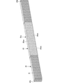
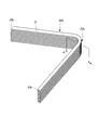
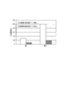
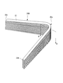
- FIG. 1 It is a figure which shows the state which attached to the stator the coil for rotary electric machines obtained with the manufacturing method of the coil for rotary electric machines which concerns on main embodiment of this invention. It is a perspective view of the state which wound the heat contraction tape around the layered product which simulated the coil for the above-mentioned rotating electrical machines. It is a perspective view of the state which heat-processed and formed the said laminated body. It is a perspective view of the test body formed by peeling off the heat shrinkable tape. It is a graph which shows the effect by the manufacturing method of the said coil for rotary electric machines. It is a perspective view of the comparative body formed by shape
- the method for forming a coil end portion which is a method for manufacturing a coil for a rotating electrical machine according to this embodiment, before the coil end portion of a coil for a rotating electrical machine made of a plurality of strands is formed by a molding machine (forming machine), A heat-shrinkable tape is wound around the outer peripheral portion corresponding to the knuckle portion forming the U-shaped corner portion of the coil end portion, and heat treatment is performed on this. Thereby, in the part corresponding to the knuckle part of a coil end part, a some strand is tightly bundled with a heat shrink tape.
- the heat shrinkable tape for example, a tape made of a material that shrinks under heating conditions but has no reactivity with a coil for a rotating electrical machine and can be easily peeled even after heat treatment, and is made of polyester Is preferably used.
- the heat treatment condition it is preferable to hold the rotating electric machine coil for a predetermined time (for example, 1 hour) in a thermostatic chamber that can be held at a temperature at which the heat-shrinkable tape contracts.
- a predetermined time for example, 1 hour
- the coil for rotating electrical machines has a coil side portion and a coil end portion having a predetermined shape.
- the coil end portion 10 a of the rotating electrical machine coil 10 includes a knuckle portion 10 aa and an oblique side portion (inclined portion) in which one end side is connected to the knuckle portion 10 aa and the other end side is connected to the coil side portion 10 b. 10ab.
- the knuckle part 10aa forms a U-shaped corner.
- the coil side part 10b has comprised the shape extended linearly.
- the heat shrinkable tape is peeled off from the coil for rotating electrical machine 10 after being molded.
- the coil for a rotating electrical machine formed into a predetermined shape by the above-described procedure is fixed in a state where the coil side portion 10b of the coil for rotating electrical machine 10 is inserted into the slot of the stator 14, as shown in FIG.
- the coil end portion 10 a of the rotating electrical machine coil 10 is fixed in a state of protruding from the stator 14.
- Reference numeral 12 denotes a portion before being attached to the stator 14 and covers the outer peripheral portion 10aa of the portion corresponding to the knuckle portion 10aa of the coil end portion 10a of the coil 10 for the rotating electrical machine when being molded by the molding machine, and contracted by heat treatment. Shows heat shrink tape.
- the heat-shrinkable tape 12 is wound around the outer peripheral portion 10aaa corresponding to the knuckle portion 10aa, and the heat-shrinkable tape 12 is contracted by the heat treatment to form a plurality of elements constituting the coil for the rotating electrical machine. Since the wires are tightly gathered, it is possible to prevent the plurality of strands from being scattered when the rotating electrical machine coil 10 is formed into a predetermined shape. Therefore, despite the fact that it is almost the same as the current manufacturing method, the occurrence of strand breakage can be effectively suppressed, and work efficiency is improved.
- the heat-shrinkable tape 12 that has been heat-treated after the coil end portion 10a is formed can be easily peeled off, varnish impregnation and winding of mica tape, which are the next steps, are performed on the entire coil end portion 10a. It can be done reliably. Moreover, generation
- a confirmation test for confirming the operational effects of the method for manufacturing a coil for a rotating electrical machine according to the present embodiment will be described below with reference to FIGS. 2 to 4, but the present invention is limited only to the confirmation test described below. Is not to be done.
- ⁇ Test body> As shown in FIG. 2A, a plurality of rectangular parallelepiped strands (metal plates) 21 are laminated to form a laminated body 20 (simulated product of a rotating electrical machine coil) corresponding to a knuckle portion in a coil end portion of the rotating electrical machine coil.
- the outer periphery (upper surface portion 20aa, side surface portion 20ab, and lower surface portion 20ac) of the central portion 20a of the laminate 20 is covered with the heat-shrinkable tape 22, and the heat treatment is performed for 1 hour in a constant temperature bath at 150 ° C. carry out.
- the heat shrinkable tape 22 contracts, and the central portion 20a of the laminate 20 composed of the plurality of strands 21 (the portion corresponding to the knuckle portion in the coil end portion of the rotating electrical machine coil) is tightly gathered. .
- a test body 20 ⁇ / b> A is obtained by peeling off the heat shrinkable tape 22 from the molded laminate 20.
- the step of covering the central portion of the laminate with the heat shrink tape, the step of performing the heat treatment, and the step of peeling off the heat shrink tape are omitted. Except for these steps, the test body 20A is almost the same. In the same procedure, as shown in FIG. 4, it was molded into a V shape substantially the same as that of the test body 20A, and the resultant was used as a comparative body 20B. That is, a laminated body 20 formed by laminating a plurality of strands 21 having a rectangular parallelepiped shape is processed into a V shape by performing processing such as expansion, bending, and twisting with a molding machine in the same manner as the test body 20A. Let it be a comparative body 20B.
- the stress is likely to concentrate and the dimensional error is the largest, and in the section along the line AA ′ corresponding to the center portion, the size in the height direction and the width direction Each size was measured, and a dimensional error was calculated from the measurement result and the design dimension (dimension before molding).
- the comparative body 20B is a portion where stress is easily concentrated and the dimensional error is the largest, and in the cross section along the line BB ′ corresponding to the center portion, The size and the size in the width direction were measured, respectively, and the dimensional error was calculated from the measurement result and the design dimensions (dimensions before molding).
- the method for manufacturing a coil for a rotating electrical machine according to the present invention is almost the same as the current manufacturing method, it is possible to effectively suppress the occurrence of strand breakage.
- the method for preventing voids in the outer insulation of the stator core in particular, the method for preventing voids before forming the stator coil, can be used extremely beneficially industrially.
- 10 Coil for rotating electrical machine 10a Coil end part, 10aa knuckle part, 10aa outer periphery part, 10ab oblique side part (inclined part), 10b coil side part, 12 heat shrink tape, 14 stator, 20 laminate, 20A test body, 20B comparison Body, 20a center part, 20aa upper surface part (peripheral part), 20ab side part (peripheral part), 20ac lower surface part (peripheral part), 20b side end part, 21 strand (metal plate), 22 heat shrink tape
Landscapes
- Engineering & Computer Science (AREA)
- Power Engineering (AREA)
- Manufacturing & Machinery (AREA)
- Manufacture Of Motors, Generators (AREA)
- Insulation, Fastening Of Motor, Generator Windings (AREA)
Abstract
現行の製造方法とほとんど変わらないにも関わらず、素線崩れの発生を効果的に抑制することができる回転電機用コイルの製造方法を提供することにある。複数の素線からなる回転電機用コイルのコイルエンド部のナックル部に対応する箇所の外周部に熱収縮テープを巻き、加熱処理を行った後に、前記コイルエンド部を所定の形状に成形する。
Description
本発明は、回転電機用コイルの製造方法に関する。
発電機(回転電機)の固定子において、回転電機用コイルの形状は多種多様であり、その成形にはフォーミングマシンと呼ばれる機械(成形機)が用いられ、拡げや曲げ、ねじりといった加工が施される。
上述した回転電機用コイルの成形の際、コイル形状によって差異はあるものの、回転電機用コイルのコイルエンド部には相当な負荷がかかり、素線崩れが発生してしまうことがある。素線崩れは見栄えが悪くなるだけでなく、テーピングする際に空隙を作ってしまう原因となりうる。空隙が生じることによりレジンが抜け落ちて放熱性能が悪化し、冷却能力の低下を招いてしまう可能性があった。また、あまりに加工が厳しすぎるとテープの破断に至ってしまうことがある。
そのため、現行の製造方法とほとんど変わらないにも関わらず、素線崩れの発生を効果的に抑制することが望まれていた。
以上のことから、本発明は、前述した問題に鑑み提案されたもので、現行の製造方法とほとんど変わらないにも関わらず、素線崩れの発生を効果的に抑制することができる回転電機用コイルの製造方法を提供することを目的としている。
前述した課題を解決する第1の発明に係る回転電機用コイルの製造方法は、
回転電機用コイルを製造する方法であって、
複数の素線からなる回転電機用コイルのコイルエンド部のナックル部に対応する箇所の外周部に熱収縮テープを巻き、加熱処理を行った後に、前記コイルエンド部を所定の形状に成形した
ことを特徴とする。
回転電機用コイルを製造する方法であって、
複数の素線からなる回転電機用コイルのコイルエンド部のナックル部に対応する箇所の外周部に熱収縮テープを巻き、加熱処理を行った後に、前記コイルエンド部を所定の形状に成形した
ことを特徴とする。
前述した課題を解決する第2の発明に係る回転電機用コイルの製造方法は、第1の発明に係る回転電機用コイルの製造方法であって、
成形後の前記回転電機用コイルから前記熱収縮テープを剥がす
ことを特徴とする。
成形後の前記回転電機用コイルから前記熱収縮テープを剥がす
ことを特徴とする。
前述した課題を解決する第3の発明に係る回転電機用コイルの製造方法は、第1の発明に係る回転電機用コイルの製造方法であって、
前記熱収縮テープとして、ポリエステル製テープを用いる
ことを特徴とする。
前記熱収縮テープとして、ポリエステル製テープを用いる
ことを特徴とする。
前述した課題を解決する第4の発明に係る回転電機用コイルの製造方法は、第2の発明に係る回転電機用コイルの製造方法であって、
前記熱収縮テープとして、ポリエステル製テープを用いる
ことを特徴とする。
前記熱収縮テープとして、ポリエステル製テープを用いる
ことを特徴とする。
前述した課題を解決する第5の発明に係る回転電機用コイルの製造方法は、第1の発明に係る回転電機用コイルの製造方法であって、
前記加熱処理は、前記熱収縮テープが収縮する温度に保持可能な恒温槽で行う
ことを特徴とする。
前記加熱処理は、前記熱収縮テープが収縮する温度に保持可能な恒温槽で行う
ことを特徴とする。
前述した課題を解決する第6の発明に係る回転電機用コイルの製造方法は、第1の発明に係る回転電機用コイルの製造方法であって、
前記加熱処理は、前記熱収縮テープが収縮する温度に加熱可能な加熱工具で行う
ことを特徴とする。
前記加熱処理は、前記熱収縮テープが収縮する温度に加熱可能な加熱工具で行う
ことを特徴とする。
本発明によれば、ナックル部に対応する箇所の外周部が熱収縮テープで巻かれ、この熱収縮テープが加熱処理で収縮して複数の素線が固くまとめられることから、所定の形状に成形するときに、複数の素線がばらけることが防止される。よって、現行の製造方法とほとんど変わらないにも関わらず、素線崩れの発生を効果的に抑制することができ、作業効率が向上する。また、絶縁層内の空隙の発生を防止することができる。これにより、熱伝導性能が向上し、巻線の温度低下が可能となる。
本発明の主な実施形態に係る回転電機用コイルの製造方法について、以下に説明するが、本発明は、以下の実施形態のみに限定されるものではない。
[主な実施形態]
本発明の主な実施形態に係る回転電機用コイルの製造方法について、図1に基づいて説明する。
本発明の主な実施形態に係る回転電機用コイルの製造方法について、図1に基づいて説明する。
本実施形態に係る回転電機用コイルの製造方法であるコイルエンド部の成形方法では、複数の素線からなる回転電機用コイルのコイルエンド部を成形機(フォーミングマシン)で成形する前に、このコイルエンド部のU字状角部をなすナックル部に対応する箇所の外周部に熱収縮テープを巻き、これに対し加熱処理を実施する。これにより、コイルエンド部のナックル部に対応する箇所にあっては、複数の素線が熱収縮テープで固くまとめられることになる。
前記熱収縮テープとして、例えば、加熱条件で収縮するが回転電機用コイルなどとの反応性が無く、加熱処理後であっても容易に剥がすことが可能な素材のテープであって、ポリエステル製テープを用いることが好ましい。
加熱処理条件として、熱収縮テープが収縮する温度に保持可能な恒温槽内に前記回転電機用コイルを所定時間(例えば1時間)保持することが好ましい。また、作業性を考慮すると、ドライヤなどの手持可能な加熱工具を用いて、ナックル部に対応する箇所のみを加熱することが好ましい。
続いて、成形機により、拡げや曲げ、ねじりといった加工が前記回転電機用コイルに施されて所定の形状に成形される。回転電機用コイルは、所定の形状をなすコイルサイド部およびコイルエンド部を有する。回転電機用コイル10のコイルエンド部10aは、例えば、図1に示すように、ナックル部10aaと、一端側がナックル部10aaと接続し他端側がコイルサイド部10bと接続する斜辺部(傾斜部)10abとを有する。ナックル部10aaは、U字状角部をなしている。なお、コイルサイド部10bは、直線状に延在する形状をなしている。
続いて、成形後の前記回転電機用コイル10から前記熱収縮テープが剥がされる。
上述した手順で所定の形状に成形された回転電機用コイルは、図1に示すように、ステータ14のスロットに回転電機用コイル10のコイルサイド部10bが挿入された状態で固定される。すなわち、ステータ14から回転電機用コイル10のコイルエンド部10aが突出した状態で固定される。なお、符号12は、ステータ14に取り付ける前であって、成形機による成形時に、回転電機用コイル10のコイルエンド部10aのナックル部10aaに対応する箇所の外周部10aaaを覆い、加熱処理で収縮する熱収縮テープを示している。
したがって、本実施形態によれば、ナックル部10aaに対応する箇所の外周部10aaaに熱収縮テープ12を巻き、この熱収縮テープ12が加熱処理で収縮して回転電機用コイルを構成する複数の素線が固くまとめられることから、回転電機用コイル10を所定の形状に成形するときに、複数の素線がばらけることが防止される。よって、現行の製造方法とほとんど変わらないにも関わらず、素線崩れの発生を効果的に抑制することができ、作業効率が向上する。また、コイルエンド部10aを成形した後に加熱処理された熱収縮テープ12を容易に剥がせることから、次工程であるワニスの含浸や、マイカテープの巻回をコイルエンド部10aの全体に対して確実に行うことができる。また、絶縁層内の空隙の発生を防止することできる。これにより、熱伝導性能が向上し、巻線の温度低下が可能となる。
本実施例に係る回転電機用コイルの製造方法の作用効果を確認するための確認試験について、図2~図4を用いて以下に説明するが、本発明は以下に説明する確認試験のみに限定されるものではない。
<試験体>
図2Aに示すように、直方体形状をなす素線(金属板)21を複数積層して積層体20(回転電機用コイルの模擬品)とし、回転電機用コイルのコイルエンド部におけるナックル部に対応する箇所として積層体20の中央部20aの外周部(上面部20aaおよび側面部20abおよび下面部20ac)を熱収縮テープ22で覆い、150℃の恒温槽内に1時間保持する条件で加熱処理を実施する。これにより、熱収縮テープ22が収縮して、複数の素線21からなる積層体20の中央部20a(回転電機用コイルのコイルエンド部におけるナックル部に対応する箇所)が固くまとめられることになる。
図2Aに示すように、直方体形状をなす素線(金属板)21を複数積層して積層体20(回転電機用コイルの模擬品)とし、回転電機用コイルのコイルエンド部におけるナックル部に対応する箇所として積層体20の中央部20aの外周部(上面部20aaおよび側面部20abおよび下面部20ac)を熱収縮テープ22で覆い、150℃の恒温槽内に1時間保持する条件で加熱処理を実施する。これにより、熱収縮テープ22が収縮して、複数の素線21からなる積層体20の中央部20a(回転電機用コイルのコイルエンド部におけるナックル部に対応する箇所)が固くまとめられることになる。
なお、前記熱収縮テープ22として、Dunstone社製の収縮率20%のものを使用した。
続いて、図2Bに示すように、中央部20aが支点となるように一方の端部20b側から略中央部20aに亘って成形機(図示せず)で固定し、拡げや曲げ、ねじりといった加工を施して中央部20aを略V字状に成形する。
続いて、図2Cに示すように、成形後の積層体20から熱収縮テープ22を剥がして得られたものを試験体20Aとする。
<比較体>
比較体の製造方法においては、熱収縮テープで積層体の中央部を覆う工程と、加熱処理を施す工程と、熱収縮テープを剥がす工程とを省き、これらの工程以外は、試験体20Aとほぼ同様な手順で、図4に示すように、試験体20Aとほぼ同じV字状に成形し、得られたものを比較体20Bとした。すなわち、直方体形状をなす素線21を複数積層してなる積層体20を成形機で試験体20Aと同様に、拡げや曲げ、ねじりといった加工を施しV字状に成形し、得られたものを比較体20Bとする。
比較体の製造方法においては、熱収縮テープで積層体の中央部を覆う工程と、加熱処理を施す工程と、熱収縮テープを剥がす工程とを省き、これらの工程以外は、試験体20Aとほぼ同様な手順で、図4に示すように、試験体20Aとほぼ同じV字状に成形し、得られたものを比較体20Bとした。すなわち、直方体形状をなす素線21を複数積層してなる積層体20を成形機で試験体20Aと同様に、拡げや曲げ、ねじりといった加工を施しV字状に成形し、得られたものを比較体20Bとする。
<試験方法>
上述の試験体20Aに対し、応力が集中し易く寸法誤差が最も大きくなる箇所であって、中央部に対応するA-A´線に沿う断面にて、高さ方向の大きさおよび幅方向の大きさをそれぞれ計測し、計測結果と設計時の寸法(成形前の寸法)とから寸法誤差を算出した。比較体20Bに対しても、試験体20Aと同様、応力が集中し易く寸法誤差が最も大きくなる箇所であって、中央部に対応するB-B´線に沿う断面にて、高さ方向の大きさおよび幅方向の大きさをそれぞれ計測し、計測結果と設計時の寸法(成形前の寸法)とから寸法誤差を算出した。
上述の試験体20Aに対し、応力が集中し易く寸法誤差が最も大きくなる箇所であって、中央部に対応するA-A´線に沿う断面にて、高さ方向の大きさおよび幅方向の大きさをそれぞれ計測し、計測結果と設計時の寸法(成形前の寸法)とから寸法誤差を算出した。比較体20Bに対しても、試験体20Aと同様、応力が集中し易く寸法誤差が最も大きくなる箇所であって、中央部に対応するB-B´線に沿う断面にて、高さ方向の大きさおよび幅方向の大きさをそれぞれ計測し、計測結果と設計時の寸法(成形前の寸法)とから寸法誤差を算出した。
試験体20Aの寸法誤差は、図3に示すように、比較体20Bの寸法誤差と比べて、幅(幅方向)および高さ(高さ方向)の何れも小さいことが確認された。すなわち、応力が集中する回転電機用コイルのコイルエンド部のナックル部に対応する箇所を熱収縮テープで覆い、加熱処理した後に、所定の形状に成形し、熱収縮テープを剥がすだけで、現行の製造方法とほとんど変わらないにも関わらず、素線崩れの発生を効果的に抑制することができることが確認された。
本発明に係る回転電機用コイルの製造方法は、現行の製造方法とほとんど変わらないにも関わらず、素線崩れの発生を効果的に抑制することができるので、発電機の固定子絶縁技術のうち、固定子鉄心外部絶縁の空隙を防止する手法、特に、固定子コイルの成形前の空隙防止方法において、産業上、極めて有益に利用することができる。
10 回転電機用コイル、10a コイルエンド部、10aa ナックル部、10aaa 外周部、10ab 斜辺部(傾斜部)、10b コイルサイド部、12 熱収縮テープ、14 ステータ、20 積層体、20A 試験体、20B 比較体、20a 中央部、20aa 上面部(外周部)、20ab 側面部(外周部)、20ac 下面部(外周部)、20b 側端部、21 素線(金属板)、22 熱収縮テープ
Claims (6)
- 回転電機用コイルを製造する方法であって、
複数の素線からなる回転電機用コイルのコイルエンド部のナックル部に対応する箇所の外周部に熱収縮テープを巻き、加熱処理を行った後に、前記コイルエンド部を所定の形状に成形した
ことを特徴とする回転電機用コイルの製造方法。 - 請求項1に記載された回転電機用コイルの製造方法であって、
成形後の前記回転電機用コイルから前記熱収縮テープを剥がす
ことを特徴とする回転電機用コイルの製造方法。 - 請求項1に記載された回転電機用コイルの製造方法であって、
前記熱収縮テープとして、ポリエステル製テープを用いる
ことを特徴とする回転電機用コイルの製造方法。 - 請求項2に記載された回転電機用コイルの製造方法であって、
前記熱収縮テープとして、ポリエステル製テープを用いる
ことを特徴とする回転電機用コイルの製造方法。 - 請求項1に記載された回転電機用コイルの製造方法であって、
前記加熱処理は、前記熱収縮テープが収縮する温度に保持可能な恒温槽で行う
ことを特徴とする回転電機用コイルの製造方法。 - 請求項1に記載された回転電機用コイルの製造方法であって、
前記加熱処理は、前記熱収縮テープが収縮する温度に加熱可能な加熱工具で行う
ことを特徴とする回転電機用コイルの製造方法。
Applications Claiming Priority (2)
| Application Number | Priority Date | Filing Date | Title |
|---|---|---|---|
| JP2015166385A JP6127309B2 (ja) | 2015-08-26 | 2015-08-26 | 回転電機用コイルの製造方法 |
| JP2015-166385 | 2015-08-26 |
Publications (1)
| Publication Number | Publication Date |
|---|---|
| WO2017034010A1 true WO2017034010A1 (ja) | 2017-03-02 |
Family
ID=58100460
Family Applications (1)
| Application Number | Title | Priority Date | Filing Date |
|---|---|---|---|
| PCT/JP2016/074896 Ceased WO2017034010A1 (ja) | 2015-08-26 | 2016-08-26 | 回転電機用コイルの製造方法 |
Country Status (2)
| Country | Link |
|---|---|
| JP (1) | JP6127309B2 (ja) |
| WO (1) | WO2017034010A1 (ja) |
Citations (4)
| Publication number | Priority date | Publication date | Assignee | Title |
|---|---|---|---|---|
| JPS56150811A (en) * | 1980-04-24 | 1981-11-21 | Toshiba Corp | Manufacture of electric parts impregnated with resin |
| JPH10295063A (ja) * | 1997-04-18 | 1998-11-04 | Toshiba Corp | 電気機器巻線の樹脂含浸・硬化方法 |
| JP2013138594A (ja) * | 2011-11-30 | 2013-07-11 | Sumitomo Electric Ind Ltd | セグメントコイル、セグメントコイルの製造方法、セグメントコイル用線材及びステータ |
| JP2013236523A (ja) * | 2012-05-11 | 2013-11-21 | Toyota Motor Corp | 集合導線および集合導線を加工したコイルならびにコイルの製造方法 |
-
2015
- 2015-08-26 JP JP2015166385A patent/JP6127309B2/ja not_active Expired - Fee Related
-
2016
- 2016-08-26 WO PCT/JP2016/074896 patent/WO2017034010A1/ja not_active Ceased
Patent Citations (4)
| Publication number | Priority date | Publication date | Assignee | Title |
|---|---|---|---|---|
| JPS56150811A (en) * | 1980-04-24 | 1981-11-21 | Toshiba Corp | Manufacture of electric parts impregnated with resin |
| JPH10295063A (ja) * | 1997-04-18 | 1998-11-04 | Toshiba Corp | 電気機器巻線の樹脂含浸・硬化方法 |
| JP2013138594A (ja) * | 2011-11-30 | 2013-07-11 | Sumitomo Electric Ind Ltd | セグメントコイル、セグメントコイルの製造方法、セグメントコイル用線材及びステータ |
| JP2013236523A (ja) * | 2012-05-11 | 2013-11-21 | Toyota Motor Corp | 集合導線および集合導線を加工したコイルならびにコイルの製造方法 |
Also Published As
| Publication number | Publication date |
|---|---|
| JP6127309B2 (ja) | 2017-05-17 |
| JP2017046436A (ja) | 2017-03-02 |
Similar Documents
| Publication | Publication Date | Title |
|---|---|---|
| KR101340168B1 (ko) | 스테이터 권선 코일의 비용접 결선방법 및 이를 적용한 회전모터 | |
| US9502949B2 (en) | Stator of motor having bus-bar wiring structure and method of wiring coil in parallel using the same | |
| WO2014136497A1 (ja) | バスバーユニット | |
| US8720042B2 (en) | Stator manufacturing method and stator | |
| CN106849435B (zh) | 旋转电机 | |
| JP6021772B2 (ja) | 回転電機 | |
| WO2011039850A1 (ja) | ステータ及びその製造方法 | |
| JP2009303335A (ja) | ステータ | |
| KR20150128818A (ko) | 소선 조립체 및 소선 조립체의 제조 방법 | |
| JP6324015B2 (ja) | 回転電機の製造方法 | |
| WO2016101983A1 (en) | Segmented stator and method of manufacturing the same | |
| JP6127309B2 (ja) | 回転電機用コイルの製造方法 | |
| EP2594013B1 (en) | Method for forming electrodynamic machine insulated coils | |
| JP2008306816A (ja) | 分割ステータの製造方法、ステータの製造方法及びモータの製造方法 | |
| JP6090045B2 (ja) | 集合導線の製造方法 | |
| JP2009289859A (ja) | モールドコイルの製造方法 | |
| CA2984122C (en) | Method of making multi-turn coils | |
| JP5944713B2 (ja) | 固定子の製造方法 | |
| JP2016163444A (ja) | ステータ | |
| JP2013121210A (ja) | 回転電機の巻線コイル製造方法 | |
| JP2017046411A (ja) | ロータコアの永久磁石固定方法 | |
| JP7452272B2 (ja) | 電機子の製造方法及び電機子 | |
| JP2007097315A (ja) | 型巻コイルの製造方法およびその型巻コイル | |
| JP7516862B2 (ja) | 電機子の製造方法 | |
| JP2012023788A (ja) | 回転電機 |
Legal Events
| Date | Code | Title | Description |
|---|---|---|---|
| 121 | Ep: the epo has been informed by wipo that ep was designated in this application |
Ref document number: 16839357 Country of ref document: EP Kind code of ref document: A1 |
|
| NENP | Non-entry into the national phase |
Ref country code: DE |
|
| 122 | Ep: pct application non-entry in european phase |
Ref document number: 16839357 Country of ref document: EP Kind code of ref document: A1 |