WO2017033909A1 - コンベヤベルトの製造方法 - Google Patents
コンベヤベルトの製造方法 Download PDFInfo
- Publication number
- WO2017033909A1 WO2017033909A1 PCT/JP2016/074456 JP2016074456W WO2017033909A1 WO 2017033909 A1 WO2017033909 A1 WO 2017033909A1 JP 2016074456 W JP2016074456 W JP 2016074456W WO 2017033909 A1 WO2017033909 A1 WO 2017033909A1
- Authority
- WO
- WIPO (PCT)
- Prior art keywords
- conveyor belt
- molded body
- release sheet
- cover rubber
- sheet
- Prior art date
- Legal status (The legal status is an assumption and is not a legal conclusion. Google has not performed a legal analysis and makes no representation as to the accuracy of the status listed.)
- Ceased
Links
Images


Classifications
-
- B—PERFORMING OPERATIONS; TRANSPORTING
- B29—WORKING OF PLASTICS; WORKING OF SUBSTANCES IN A PLASTIC STATE IN GENERAL
- B29D—PRODUCING PARTICULAR ARTICLES FROM PLASTICS OR FROM SUBSTANCES IN A PLASTIC STATE
- B29D29/00—Producing belts or bands
- B29D29/06—Conveyor belts
-
- B—PERFORMING OPERATIONS; TRANSPORTING
- B65—CONVEYING; PACKING; STORING; HANDLING THIN OR FILAMENTARY MATERIAL
- B65G—TRANSPORT OR STORAGE DEVICES, e.g. CONVEYORS FOR LOADING OR TIPPING, SHOP CONVEYOR SYSTEMS OR PNEUMATIC TUBE CONVEYORS
- B65G15/00—Conveyors having endless load-conveying surfaces, i.e. belts and like continuous members, to which tractive effort is transmitted by means other than endless driving elements of similar configuration
- B65G15/30—Belts or like endless load-carriers
-
- B—PERFORMING OPERATIONS; TRANSPORTING
- B65—CONVEYING; PACKING; STORING; HANDLING THIN OR FILAMENTARY MATERIAL
- B65G—TRANSPORT OR STORAGE DEVICES, e.g. CONVEYORS FOR LOADING OR TIPPING, SHOP CONVEYOR SYSTEMS OR PNEUMATIC TUBE CONVEYORS
- B65G15/00—Conveyors having endless load-conveying surfaces, i.e. belts and like continuous members, to which tractive effort is transmitted by means other than endless driving elements of similar configuration
- B65G15/30—Belts or like endless load-carriers
- B65G15/32—Belts or like endless load-carriers made of rubber or plastics
Definitions
- the present invention relates to a method for manufacturing a conveyor belt, and more specifically, a method for manufacturing a conveyor belt capable of manufacturing a conveyor belt having an excellent appearance quality with a smooth surface and suppressed adhesion of dirt while improving the working environment. It is about.
- a molded body in which the core layer is sandwiched between the unvulcanized upper cover rubber and lower cover rubber is manufactured.
- the core layer a structure in which a large number of steel cords are arranged side by side or a canvas is used.
- the core body layer, the upper cover rubber, and the lower cover rubber are integrated by vulcanizing the molded body with a hot plate.
- a powder such as talc is applied to the surface of the upper cover rubber and lower cover rubber, or a release agent is applied to the surface of the hot plate. Application is performed.
- talc or mold release agent when talc or mold release agent is scattered around, the working environment is deteriorated. Moreover, it is difficult to apply talc and a release agent uniformly. When the partially remaining talc and the release agent are deposited on the hot plate surface with time, irregularities are formed on the surface of the vulcanized conveyor belt, so that the appearance quality of the conveyor belt is deteriorated. In addition, talc and mold release agent function as an air release layer during vulcanization, but in such a non-uniform state, sufficient bleed function cannot be exhibited and vulcanization failure occurs. It becomes easy to do. In order to prevent this vulcanization failure, if more release agent is applied, for example, a vicious cycle occurs and the vulcanization failure cannot be fundamentally solved.
- Patent Document 1 a method of manufacturing a conveyor belt that does not use talc or a mold release agent has been proposed (see Patent Document 1).
- a molded body is vulcanized with a sheet-like intermediate material made of a low friction coefficient resin interposed between the surface of the molded body and a hot plate.
- the sheet-like intermediate material a core sheet made of woven fabric or knitted fabric is used. The air venting function at the time of vulcanization is secured through the unevenness of the pattern on the surface of the sheet-like intermediate material.
- the pattern of the woven or knitted fabric forming the sheet-like intermediate material is transferred onto the surface of the manufactured conveyor belt. If such a pattern is transferred to the surface of the conveyor belt, there is a possibility of improvement in appearance quality, so there is room for improvement.
- An object of the present invention is to provide a conveyor belt manufacturing method capable of manufacturing a conveyor belt excellent in appearance quality with a smooth surface and suppressed adhesion of dirt while improving the working environment.
- the method for manufacturing a conveyor belt according to the present invention includes forming an unvulcanized upper cover rubber and a lower cover rubber on each of the upper surface and the lower surface of the core layer to form a conveyor belt molded body,
- a manufacturing method of a conveyor belt for vulcanizing while maintaining a state in which the molded body is sandwiched and fixed between opposed hot plates for a predetermined time between the upper cover rubber and one of the hot plates and the lower cover rubber A release sheet is interposed between the heat plate and the other heat plate, and the molded sheet is sandwiched between the heat plate with the release sheet in contact with the upper cover rubber and the lower cover rubber.
- the release sheet is peeled off from the conveyor belt produced by vulcanizing and then vulcanizing the molded body, and the water contact angle is 70 ° or more and the dynamic friction coefficient is 0.3 or less as the release sheet. Saga 0.2mm or 0.4mm or less, the sheet surface in contact with the molded body, characterized by using a smooth sheet.
- the manufactured conveyor belt can be used without using a powder such as talc or a release agent. It is possible to prevent a mold release failure between the surface and the hot plate and contamination of the hot plate. Therefore, there is no deterioration of the working environment due to the scattering of talc and mold release agent. Dirt caused by talc or mold release agent does not adhere to the surface of the manufactured conveyor belt.
- the water contact angle of the release sheet is 70 ° or more
- the dynamic friction coefficient is 0.3 or less
- the sheet thickness is 0.2 mm or more and 0.4 mm or less
- the sheet surface in contact with the molded body is smooth.
- the air can be sufficiently removed through the upper cover rubber, the lower cover rubber and the release sheet.
- the surface of the manufactured conveyor belt becomes flat both macroscopically and microscopically, and it becomes possible to make the product excellent in appearance quality with a smooth surface and suppressed adhesion of dirt.
- the release sheet a reinforcing material made of a material having higher thermal conductivity than the base material of the release sheet is embedded in a state where it is not exposed at least on the surface of the sheet that contacts the molded body.
- a release sheet can also be used. In this case, wrinkles or the like hardly occur on the release sheet due to the presence of the reinforcing material, which is advantageous for smoothing the surface of the conveyor belt. In addition, it is possible to avoid the problem that the vulcanization time becomes long due to the reinforcing material.
- the molded body can be vulcanized with a predetermined tension applied to the release sheet. In this case, wrinkles or the like hardly occur on the release sheet, which is advantageous for smoothing the surface of the conveyor belt.
- the temperature of the release sheet when contacting the upper cover rubber and the lower cover rubber may be 50 ° C. or higher and the vulcanization temperature of the molded body or lower. If the release sheet is in a high temperature (50 ° C. or higher) state rather than a low temperature, generation of wrinkles can be suppressed. In particular, when the release sheet is changed from a high temperature to a low temperature, wrinkles and the like are likely to occur due to thermal shrinkage. On the other hand, if the temperature of the release sheet is higher than the vulcanization temperature of the molded body, there is a concern about thermal degradation of the release sheet.
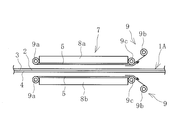
- FIG. 1 is an explanatory view illustrating the process of manufacturing the conveyor belt of the present invention in a belt longitudinal direction sectional view.
- FIG. 2 is an explanatory view illustrating a state in which the molded body is vulcanized with the hot plate of FIG.
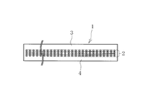
- FIG. 3 is an explanatory diagram illustrating the process of FIG. 2 in plan view.
- FIG. 4 is a longitudinal sectional view showing a modified example of the release sheet.
- FIG. 5 is a plan view of the release sheet of FIG.
- FIG. 6 is a cross-sectional view in the belt width direction illustrating the structure of the conveyor belt.
- the manufacturing method of the conveyor belt of this invention is demonstrated based on embodiment shown in the figure. 1 to 3, the direction from the left side to the right side is the moving direction of the formed body 1A (conveyor belt 1 to be manufactured), the right side is the front, and the left side is the rear.
- the conveyor belt 1 manufactured according to the present invention has an upper cover rubber 3 and a lower cover rubber 4 bonded and integrated on the upper surface and the lower surface of the core layer 2, respectively.
- the conveyor belt 1 is manufactured.
- the core layer 2 is a member that bears the tension when the conveyor belt 1 is stretched.
- the core body layer 2 is formed of a plurality of steel cords extending in the belt longitudinal direction in parallel in the belt width direction.
- the core body layer 2 is formed by making the canvas a single layer or multiple layers. More specifically, the surface of the core body layer 2 is coated with a coating rubber for adhesion, and the upper cover rubber 3 and the lower cover rubber 4 and the core body layer 2 are vulcanized and bonded via the coating rubber.
- the conveyor belt 1 is configured by adding other members as necessary.
- the conveyor belt 1 is manufactured by using the manufacturing apparatus 7 illustrated in FIGS.
- the manufacturing apparatus 7 includes hot plates 8a and 8b arranged opposite to each other and sheet feeders 9 and 9 arranged adjacent to the respective hot plates 8a and 8b.
- Each sheet feeder 9 has a feed shaft 9a, a take-up shaft 9b, and an intermediate support shaft 9c.
- Each of the hot plates 8a and 8b is a plate-like body having a flat surface facing each other, and at least one of them moves in a direction in which they approach and move away from each other (vertical direction in FIG. 1).
- the hot plates 8a and 8b are heated to a predetermined temperature by steam or the like.
- a feeding shaft 9a is disposed adjacent to the rear end of the upper hot plate 8a, and an intermediate support shaft 9c is disposed adjacent to the front end.
- the winding shaft 9b is disposed obliquely above and in front of the intermediate support shaft 9c.
- the feeding shaft 9a and the intermediate support shaft 9c are arranged so that the straight line connecting each other is substantially parallel to the lower surface of the upper hot plate 8a.
- a feeding shaft 9a is disposed adjacent to the rear end portion of the lower heat plate 8b, and an intermediate support shaft 9c is disposed adjacent to the front end portion.
- the winding shaft 9b is disposed obliquely below and in front of the intermediate support shaft 9c.
- the feeding shaft 9a and the intermediate support shaft 9c are arranged so that a straight line connecting each other is substantially parallel to the upper surface of the lower heat plate 8b.
- a release sheet 5 is wound around each feeding shaft 9a.
- the release sheet 5 is unwound from the unwinding shaft 9a, is supported by the intermediate support shaft 9c, and is wound around the winding shaft 9b.
- the take-up shaft 9b is driven to rotate, and the feed shaft 9a can be switched between a free mode in which it rotates freely and a fixed mode in which the brake does not rotate.
- the winding shaft 9b can be disposed at the position of the intermediate support shaft 9c, and the intermediate support shaft 9c can be omitted.
- the release sheet 5 has heat resistance that does not substantially permanently deform at the vulcanization temperature of the molded body 1A.
- the heat resistant temperature is, for example, 170 ° C. or higher, more preferably 180 ° C. or higher, and further preferably 200 ° C. or higher.
- the sheet thickness of the release sheet 5 is 0.2 mm or more and 0.4 mm or less, the water contact angle is 70 ° or more, and the dynamic friction coefficient is 0.3 or less.
- the water contact angle is a contact angle defined in JIS R 3257: 1999.
- the water contact angle is more preferably 100 ° or more, and closer to 180 ° is more preferable. That is, the release sheet 5 is preferably excellent in water repellency.
- the dynamic friction coefficient is a value obtained in accordance with JIS K 7125: 1999.
- the dynamic friction coefficient is more preferably 0.1 or less.
- the release sheet 5 is made of a low-friction resin material, metal material, mineral material, or a composite material thereof. Specifically, a fluororesin sheet, a diamond-like carbon sheet, a hard chrome plating sheet, and the like can be exemplified as the release sheet 5.
- the surface of the release sheet 5 is smooth.
- Smoothness in the present invention means to have both micro smoothness (small surface roughness) and macro smoothness.
- the arithmetic average roughness Ra is about 1 ⁇ m to 10 ⁇ m.
- Macroscopic smoothness means that the surface is flat without irregularities or holes on the surface.
- woven fabrics and knitted fabrics are not flat and not macroscopically smooth because uneven surfaces and holes are present on the surface due to the fibers of the constituent members. Therefore, the release sheet 5 is non-woven fabric and non-knitted fabric.
- the entire range of both surfaces of the release sheet 5 may be smooth as described above, but only the surface that contacts the molded body 1A of the release sheet 5 during vulcanization of the molded body 1A may be smooth.
- the molded body 1A is disposed between the hot plates 8a and 8b.
- the opposing surfaces of the hot plates 8a and 8b are covered with the release sheet 5, respectively.
- the release sheet 5 is interposed between the upper cover rubber 3 and the hot plate 8a and between the lower cover rubber 4 and the hot plate 8b.
- the release sheet 5 is formed in the plane of the hot plates 8a and 8b in the longitudinal direction (left and right direction in FIG. 3) and the width direction (up and down in FIG. 3) of the upper cover rubber 3 and lower cover rubber 4. It is in the state of covering the entire range of (direction).
- the feeding shaft 9a is in a fixed mode, and the take-up shaft 9b is in a state in which the rotational drive is stopped, and an appropriate tension is applied to the release sheet 5 in the longitudinal direction.
- the take-up shaft 9b is slightly rotated to apply tension to the release sheet 5. That is, the sheet feeders 9 and 9 can function as tensioners that apply tension to the release sheet 5.
- a desired tension may be applied to the release sheet 5 by adjusting the rotation amount of the winding shaft 9b.
- the tension to be applied may be a minimum tension at which the release sheet 5 is stretched without slack. When a predetermined tension is applied to the release sheet 5, wrinkles and the like are hardly generated on the release sheet 5, which is advantageous for smoothing the surface of the vulcanized conveyor belt 1.
- the temperature of the release sheet 5 when contacting the upper cover rubber 3 and the lower cover rubber 4 is preferably 50 ° C. or higher and lower than the vulcanization temperature of the molded body 1A. Specifically, the temperature of the release sheet 5 at this time is set to, for example, 50 ° C. or more and 120 ° C. or less.
- the release sheet 5 When the release sheet 5 is in a higher temperature (50 ° C. or higher) state than a low temperature, generation of wrinkles can be suppressed. For example, when the release sheet 5 is used continuously, when the release sheet 5 in a high temperature state becomes a low temperature state, wrinkles and the like are likely to occur in the release sheet 5 due to thermal contraction. On the other hand, when the temperature of the release sheet 5 is higher than the vulcanization temperature of the molded body 1A, the release sheet 5 is likely to be thermally deteriorated.
- the state in which the molded body 1A is sandwiched and fixed by the hot plates 8a and 8b as described above is maintained for a predetermined time, and the molded body 1A is heated at a predetermined temperature and pressurized at a predetermined pressure to be vulcanized.
- the predetermined temperature at the time of vulcanization (vulcanization temperature) is, for example, 140 ° C. or more and 165 ° C. or less, and the predetermined pressure is, for example, 2.0 MPa or more and 4.0 MPa or less.
- the unvulcanized upper cover rubber 3 and lower cover rubber 4 flow.
- the unstable interface between the hot plate 8a and the unvulcanized upper cover rubber 3, the hot plate 8b and the unvulcanized changes in a direction to eliminate the excess energy of the interface, and changes to a state close to the surface energy.
- the surface energy of the rubber is larger than the surface energy of the hot plates 8a and 8b, and if there are recesses such as scratches on the surfaces of the hot plates 8a and 8b, the rubber tends to collect in the recesses in an attempt to eliminate excess energy at the interface. .
- the flowing upper cover rubber 3 and lower cover rubber 4 are preferentially adsorbed from the rough portions of the surfaces of the hot plates 8a and 8b.
- the surplus energy of the rubber is not eliminated in the portions where the surfaces of the hot plates 8a and 8b are not rough, and unevenness remains on the surface of the vulcanized rubber, so that the surface of the manufactured conveyor belt 1 is smoothed. It will be disadvantageous.
- the molded body 1A is vulcanized by interposing the release sheet 5 having a water contact angle of 70 ° or more and a dynamic friction coefficient of 0.3 or less.
- the interface between the release sheet 5 and the lower cover rubber 4 has no uneven surface energy.
- the upper cover rubber 3 and the lower cover rubber 4 smoothly flow with respect to the release sheet 5, the surface of the manufactured conveyor belt 1 becomes smooth. Accordingly, it is possible to sufficiently vent the air through the upper cover rubber 3 and the lower cover rubber 4 and the release sheet 5 during vulcanization. Further, since the components of the upper cover rubber 3 and the lower cover rubber 4 are difficult to adhere to the surface of the release sheet 5, there is an advantage that the release sheet 5 can be repeatedly used without being contaminated.
- the molded body 1A is vulcanized to become the conveyor belt 1 (a part of the conveyor belt 1). After vulcanization of the molded body 1A, at least one is moved so that the hot plates 8a and 8b are separated from each other, and the release sheet 5 in contact with the manufactured conveyor belt 1 is peeled off. Since the release sheet 5 has a characteristic that the water contact angle is 70 ° or more, it can be easily peeled off from the manufactured conveyor belt 1.
- the part (vulcanized part) of the manufactured conveyor belt 1 is moved forward in the longitudinal direction, and the part to be vulcanized next to the molded body 1A is interposed between the hot plates 8a and 8b as illustrated in FIG. Deploy.
- the same process as described above is performed to vulcanize the molded body 1A.
- the part used in the previous vulcanization of the release sheet 5 can be used repeatedly, or a different part can be used.
- the feeding shaft 9a is switched to the free mode, the winding shaft 9b is driven to rotate, and the release sheet 5 is fed out by a required length in the longitudinal direction.
- the conveyor belt 1 is manufactured by sequentially shifting the molded body 1A in the longitudinal direction and vulcanizing.
- the release sheet 5 can be detachably provided on the lower surface of the hot plate 8a and the upper surface of the hot plate 8b without using the sheet feeder 9.
- the release sheet 5 may be attached to the hot plates 8a and 8b with a predetermined tension applied to the release sheet 5 through an elastic material such as a spring. .
- the manufactured conveyor belt can be used without using a powder such as talc or a release agent. 1 and the hot plates 8a and 8b can be prevented from being separated from each other, and the hot plates 8a and 8b can be prevented from being stained. Therefore, there is no deterioration of the working environment due to the scattering of talc and mold release agent. Moreover, the stain
- the sheet thickness of the release sheet 5 is 0.4 mm or less, the vulcanization time is slightly longer than when the molded body 1A is vulcanized without the release sheet 5 interposed. Degree. If the sheet thickness of the release sheet 5 becomes too thin, the handleability deteriorates, so the sheet thickness is set to 0.2 mm or more.
- the surface of the conveyor belt 1 manufactured in this way is flat both macroscopically and microscopically, and becomes a product excellent in appearance quality in which the surface is smooth and adhesion of dirt is suppressed.
- a sheet embedded with a reinforcing material 6 made of a material superior in thermal conductivity to the base material can be used as the release sheet 5.
- the reinforcing material 6 is embedded in a state where it is not exposed at least on the surface of the sheet that contacts the molded body 1 ⁇ / b> A during vulcanization.
- the reinforcing material 6 can be completely embedded without being exposed on the surface of the release sheet 5. Further, the reinforcing material 6 can be embedded over the entire length in the width direction of the release sheet 5.
- the reinforcing material 6 specifically, for example, an aluminum sheet, various metal sheets, a glass fiber sheet, or the like can be used.
- the release sheet 5 has such a specification, wrinkles or the like hardly occur in the release sheet 5 due to the presence of the reinforcing material 6, which is advantageous for smoothing the surface of the conveyor belt 1.
- the problem that the vulcanization time becomes long due to the reinforcing material 6 can be avoided.
Landscapes
- Engineering & Computer Science (AREA)
- Mechanical Engineering (AREA)
- Belt Conveyors (AREA)
- Heating, Cooling, Or Curing Plastics Or The Like In General (AREA)
Abstract
作業環境を向上させつつ、表面が平滑で汚れの付着を抑制した外観品質に優れたコンベヤベルトを製造することができるコンベヤベルトの製造方法を提供する。水接触角を70°以上、動摩擦係数を0.3以下、シート厚さを0.2mm以上0.4mm以下にするとともに、成形体1Aに接触するシート表面を平滑した離型シート5を、上カバーゴム3と一方の熱板8aとの間および下カバーゴム4と他方の熱板8bとの間に介在させて、離型シート5を上カバーゴム3および下カバーゴム4に接触させた状態にして熱板8a、8bにより成形体1Aを挟んで固定した状態を所定時間維持して加硫し、成形体1Aを加硫して製造されたコンベヤベルト1から離型シート5を剥離させる。
Description
本発明は、コンベヤベルトの製造方法に関し、さらに詳しくは、作業環境を向上させつつ、表面が平滑で汚れの付着を抑制した外観品質に優れたコンベヤベルトを製造することができるコンベヤベルトの製造方法に関するものである。
コンベヤベルトの製造工程では、心体層を未加硫の上カバーゴムおよび下カバーゴムで挟んだ状態にした成形体を製造する。心体層には、多数本のスチールコードを横並び状態にしたもの、或いは、帆布を用いる。次いで、この成形体を熱板で挟んで加硫することにより、心体層、上カバーゴムおよび下カバーゴムを一体化させる。上カバーゴムおよび下カバーゴムを熱板から離型させ易くする等の目的で、上カバーゴムおよび下カバーゴムの表面にタルク等の粉体を塗布したり、熱板の表面に離型剤を塗布することが行われている。
しかし、タルクや離型剤が周囲に飛散すると作業環境が悪化する。また、タルクや離型剤は、均一に塗布することが難しい。そして、部分的に残ったタルクや離型剤が経時的に熱板表面に堆積すると、加硫したコンベヤベルトの表面には凹凸が形成されるのでコンベヤベルトの外観品質が低下する。また、加硫時にタルクや離型剤はエア抜き層として機能するが、このように不均一に存在している状態では、十分なエア抜き機能を発揮することができず、加硫故障が発生し易くなる。この加硫故障を防止しようとして、例えば離型剤をより多く塗布すれば、悪循環になって加硫故障を根本的に解決することができなくなる。さらには、塗布したタルクや離型剤に起因する汚れが、コンベヤベルトの表面に転写されて、コンベヤベルトの外観品質が低下するという問題もある。一方、熱板表面に残ったタルクや離型剤を逐次除去する場合、この除去工程の間は、成形体を加硫することができないため、コンベヤベルトの生産性低下の要因になる。
そこで、タルク等や離型剤を使用しないコンベヤベルトの製造方法が提案されている(特許文献1参照)。特許文献1で提案されている方法では、成形体の表面と熱板との間に低摩擦係数樹脂製のシート状中間材を介在させた状態にして成形体を加硫する。シート状中間材としては、織物または編物からなる芯体シートが使用される。このシート状中間材の表面の模様の凹凸を通じて、加硫時のエア抜き機能を確保している。
しかしながら、この方法では、製造したコンベヤベルトの表面にシート状中間材を形成している織物または編物の模様が転写されることになる。このような模様がコンベヤベルトの表面に転写されていると、外観品質上、問題があると判断されることがあるため改善の余地があった。
本発明の目的は、作業環境を向上させつつ、表面が平滑で汚れの付着を抑制した外観品質に優れたコンベヤベルトを製造することができるコンベヤベルトの製造方法を提供することにある。
上記目的を達成するため本発明のコンベヤベルトの製造方法は、心体層の上面および下面それぞれに、未加硫の上カバーゴム、下カバーゴムを配置してコンベヤベルトの成形体を成形し、この成形体を対向配置された熱板により挟んで固定した状態を所定時間維持して加硫するコンベヤベルトの製造方法において、前記上カバーゴムと一方の前記熱板との間および前記下カバーゴムと他方の前記熱板との間に離型シートを介在させ、前記上カバーゴムおよび前記下カバーゴムに対して前記離型シートを接触させた状態にして前記熱板により前記成形体を挟んで加硫し、次いで前記成形体を加硫して製造されたコンベヤベルトから前記離型シートを剥離させ、前記離型シートとして、水接触角が70°以上、動摩擦係数が0.3以下、シート厚さが0.2mm以上0.4mm以下、前記成形体に接触するシート表面が平滑なシートを使用することを特徴とする。
本発明によれば、成形体と熱板との間に離型シートを介在させて成形体を加硫するので、タルク等の粉体や離型剤を使用しなくても、製造したコンベヤベルトの表面と熱板との離型不良、熱板の汚れ等を防止できる。それ故、タルクや離型剤等の飛散による作業環境の悪化がない。製造したコンベヤベルトの表面にタルクや離型剤等に起因した汚れが付着することもない。さらには、前記離型シートの水接触角が70°以上、動摩擦係数が0.3以下、シート厚さが0.2mm以上0.4mm以下であり、前記成形体に接触するシート表面が平滑であるため、加硫時には上カバーゴムおよび下カバーゴムと離型シートとの間を通じて十分にエア抜きをすることができる。そして、製造したコンベヤベルトの表面はマクロ的にもミクロ的にも平坦になり、表面が平滑で汚れの付着を抑制した外観品質に優れた製品にすることが可能になる。
ここで、前記離型シートとして、この離型シートの母材よりも熱伝導性に優れた材料からなる補強材が、少なくとも前記成形体に接触するシート表面には露出しない状態で埋設されている離型シートを使用することもできる。この場合、補強材の存在によって離型シートにシワ等が発生し難くなり、コンベヤベルトの表面を平滑にするには有利になる。加えて、補強材に起因して加硫時間が長くなるという不具合を回避できる。
前記離型シートに所定の張力を付与した状態にして前記成形体の加硫を行うこともできる。この場合、離型シートにシワ等が発生し難くなり、コンベヤベルトの表面を平滑にするには有利になる。
前記上カバーゴムおよび前記下カバーゴムに接触させる際の前記離型シートの温度を、50℃以上かつ前記成形体の加硫温度以下にするとよい。離型シートは低温よりも高温(50℃以上)の状態にした方がシワ等の発生を抑制できる。特に、離型シートは高温から低温状態になると、熱収縮によってシワ等が発生し易くなる。一方、離型シートの温度を成形体の加硫温度よりも高くすると、離型シートの熱劣化が懸念される。
以下、本発明のコンベヤベルトの製造方法を図に示した実施形態に基づいて説明す
る。尚、図1~図3では、左側から右側に向かう方向を成形体1A(製造されるコンベヤベルト1)の移動方向とし、右側を前方、左側を後方とする。
る。尚、図1~図3では、左側から右側に向かう方向を成形体1A(製造されるコンベヤベルト1)の移動方向とし、右側を前方、左側を後方とする。
図6に例示するように、本発明により製造されるコンベヤベルト1は、心体層2の上面および下面それぞれに上カバーゴム3、下カバーゴム4が接合されて一体化している。コンベヤベルト1の製造工程の詳細は後述するが、心体層2を挟んで未加硫の上カバーゴム3と未加硫の下カバーゴム4とを配置した成形体1Aを加硫することにより、コンベヤベルト1が製造される。
心体層2は、コンベヤベルト1を張設した際の張力を負担する部材である。心体層2は例えば、ベルト長手方向に延在する多数本のスチールコードがベルト幅方向に並列して形成される。或いは、帆布を単層または複層にして心体層2は形成される。詳述すると、心体層2の表面は接着用のコートゴムで被覆されていて、上カバーゴム3および下カバーゴム4と心体層2とは、コートゴムを介して加硫接着されている。コンベヤベルト1は、必要に応じて他の部材が追加されて構成される。
本発明では、図1~図3に例示する製造装置7を用いてコンベヤベルト1を製造する。この製造装置7は、対向配置された熱板8a、8bと、それぞれの熱板8a、8bに隣接配置されたシート供給機9、9とを備えている。それぞれのシート供給機9、9は、繰り出し軸9a、巻き取り軸9bおよび中間支持軸9cを有している。
それぞれの熱板8a、8bは、互いに対向する面が平坦な板状体であり、互いが近接離反する方向(図1では上下方向)に、少なくとも一方が移動する。熱板8a、8bはスチーム等によって所定温度に加熱される。
上側の熱板8aの後方側端部に隣接して繰り出し軸9aが配置され、前方側端部に隣接して中間支持軸9cが配置されている。巻き取り軸9bは中間支持軸9cの前方斜め上方に配置されている。繰り出し軸9aと中間支持軸9cとは、互いを結ぶ直線が上側の熱板8aの下面と実質的に平行になるように配置されている。下側の熱板8bの後方側端部に隣接して繰り出し軸9aが配置され、前方側端部に隣接して中間支持軸9cが配置されている。巻き取り軸9bは中間支持軸9cの前方斜め下方に配置されている。繰り出し軸9aと中間支持軸9cとは、互いを結ぶ直線が下側の熱板8bの上面と実質的に平行になるように配置されている。
それぞれの繰り出し軸9aには、離型シート5が巻き付けられている。離型シート5は繰り出し軸9aから繰り出されて、途中で中間支持軸9cにより支持されて巻き取り軸9bに巻き取られる構成になっている。巻き取り軸9bは回転駆動され、繰り出し軸9aはフリーに回転するフリーモードとブレーキが作用して回転しない固定モードとに切り替え可能になっている。中間支持軸9cの位置に巻き取り軸9bを配置して、中間支持軸9cを省略することもできる。
離型シート5は、成形体1Aの加硫温度では実質的に永久変形しない耐熱性を有している。その耐熱温度は例えば、170℃以上、より好ましくは180℃以上、さらに好ましくは200℃以上である。離型シート5のシート厚さは、0.2mm以上0.4mm以下であり、水接触角は70°以上、動摩擦係数は0.3以下の仕様になっている。
水接触角とは、JIS R 3257:1999に規定されている接触角である。水接触角は100°以上であることがより好ましく、180°に近いほど好ましい。即ち、離型シート5は、撥水性に優れていることが好ましい。
動摩擦係数は、JIS K 7125:1999に準拠して求めた値である。動摩擦係数は、より好ましくは0.1以下である。
離型シート5は、低摩擦の樹脂材料、金属材料、鉱物材料等、或いは、これらの複合材料から成っている。具体的には、フッ素樹脂シート、ダイヤモンドライクカーボンシート、ハードクロムメッキ処理シート等を離型シート5として例示できる。
離型シート5の表面は平滑になっている。本発明における平滑とは、ミクロ的な滑らかさ(表面粗さが小さい)とマクロ的な滑らかさとを兼ね備えることを意味する。ミクロ的な滑らかさについては、算術平均粗さRaが1μm~10μm程度になっている。マクロ的な滑らかさとは、目視で表面に凹凸や穴などがなく平坦であることである。例えば、織物や編物は表面に構成部材の繊維によって凹凸模様や穴が存在しているので平坦ではなく、マクロ的に滑らかではない。したがって、離型シート5は非織物および非編物である。離型シート5の両面全範囲が上述した平滑であってもよいが、成形体1Aの加硫時に離型シート5の成形体1Aに接触する表面だけが上述した平滑であってもよい。
以下、本発明のコンベヤベルトの製造方法の手順を説明する。
図1に例示するように、成形体1Aを熱板8a、8bの間に配置する。熱板8a、8bの互いに対向する表面はそれぞれ、離型シート5により被覆されている。
次いで、図2に例示するように、熱板8a、8bが近接するように少なくとも一方を移動させて、熱板8a、8bにより成形体1Aを挟んで固定した状態にする。この状態では、上カバーゴム3と熱板8aとの間および下カバーゴム4と熱板8bとの間に離型シート5が介在する。離型シート5は図3に例示するように、熱板8a、8bの平面内で、上カバーゴム3および下カバーゴム4の長手方向(図3では左右方向)および幅方向(図3では上下方向)の全範囲を覆って接触した状態になっている。
繰り出し軸9aは固定モード、巻き取り軸9bは回転駆動が停止した状態になっていて、離型シート5には長手方向に適度な張力を付与されている。繰り出し軸9aを固定モードにした後、巻き取り軸9bを若干回転駆動することで、離型シート5に張力を付与することができる。即ち、それぞれのシート供給機9、9を離型シート5に張力を付与するテンショナとして機能させることができる。巻き取り軸9bの回転量を調節することにより、離型シート5に所望の張力を付与するとよい。付与する張力は、離型シート5が弛みなく張設される最低限の張力でよい。離型シート5に所定の張力を付与すると、離型シート5にシワ等が発生し難くなり、加硫したコンベヤベルト1の表面を平滑にするには有利になる。
上カバーゴム3および下カバーゴム4に接触させる際の離型シート5の温度は、50℃以上かつ成形体1Aの加硫温度以下にすることが好ましい。具体的には、この際の離型シート5の温度を例えば50℃以上120℃以下にする。
離型シート5は低温よりも高温(50℃以上)の状態にした方がシワ等の発生を抑制できる。例えば、連続して離型シート5を使用する場合、高温状態の離型シート5が低温状態になると、熱収縮によって離型シート5にはシワ等が発生し易くなる。一方で、離型シート5の温度を成形体1Aの加硫温度よりも高くすると、離型シート5が熱劣化し易くなる。
上述のように成形体1Aを熱板8a、8bにより挟んで固定した状態を所定時間維持して、成形体1Aを所定の温度で加熱するとともに所定の圧力で加圧して加硫する。加硫する際の所定の温度(加硫温度)は例えば140℃以上165℃以下、所定の圧力は例えば2.0MPa以上4.0MPa以下である。
この加硫時には、未加硫の上カバーゴム3および下カバーゴム4が流動する。ここで、離型シート5を介在させずに成形体1Aを加硫した場合、熱板8aと未加硫の上カバーゴム3との間の不安定な界面、熱板8bと未加硫の下カバーゴム4との間の不安定な界面はそれぞれ、界面の余剰エネルギを解消する方向に変化して、最も表面エネルギ的に近いどうしの状態に変化する。そして、ゴムの表面エネルギは熱板8a、8bの表面エネルギよりも大きく、熱板8a、8bの表面に傷などの凹部が存在すると、界面の余剰エネルギを解消しようとしてゴムが凹部に集まり易くなる。即ち、流動する上カバーゴム3、下カバーゴム4は、熱板8a、8bの表面の粗い部分から優先的に吸着する。その結果、熱板8a、8bの表面の粗くない部分では、ゴムの余剰エネルギが解消されず、加硫されたゴム表面には凹凸が残るため、製造されたコンベヤベルト1の表面を平滑にするには不利になる。
一方、本発明では、水接触角が70°以上、動摩擦係数が0.3以下の離型シート5を介在させて成形体1Aを加硫するので、離型シート5とカバーゴム3との間の界面、離型シート5と下カバーゴム4との間の界面はそれぞれ、表面エネルギの偏りがない。しかも、上カバーゴム3および下カバーゴム4は離型シート5に対して滑らかに流動するので、製造されたコンベヤベルト1の表面が平滑になる。これに伴って、加硫時には上カバーゴム3および下カバーゴム4と離型シート5との間を通じて十分にエア抜きをすることも可能になる。また、離型シート5の表面には、上カバーゴム3や下カバーゴム4の成分が付着し難いので、離型シート5を汚れがない状態で繰り返し使用できるメリットもある。
この加硫を経て、成形体1Aは加硫されてコンベヤベルト1(コンベヤベルト1の一部分)になる。成形体1Aの加硫後は、熱板8a、8bが離反するように少なくとも一方を移動させ、製造されたコンベヤベルト1に接触している離型シート5を剥離させる。離型シート5は、水接触角が70°以上の特性を有しているので、製造したコンベヤベルト1から容易に剥離させることができる。
その後、製造したコンベヤベルト1の部分(加硫した部分)を長手方向前方に移動させて、成形体1Aの次に加硫する部分を図1に例示するように熱板8a、8bの間に配置する。次いで、既述した同様の工程を行って成形体1Aを加硫する。この際に、離型シート5の先の加硫で使用した部分(成形体1Aに接触させた部分)を繰り返し用いることも、異なる部分を用いることもできる。異なる部分を用いる場合は、繰り出し軸9aをフリーモードに切り替えて、巻き取り軸9bを回転駆動させて、離型シート5を長手方向に必要長さだけ繰り出す。このように順次、成形体1Aを長手方向にずらして加硫することによりコンベヤベルト1を製造する。
シート供給機9を使用せずに、例えば、熱板8aの下面、熱板8bの上面にそれぞれ、離型シート5を着脱自在に設けることもできる。離型シート5を熱板8a、8bに着脱自在に設ける場合、スプリング等の弾性材を介在させて、離型シート5に所定の張力を付与した状態にして熱板8a、8bに取り付けるとよい。
本発明では、熱板8a、8bと成形体1Aの間に離型シート5を介在させて加硫を行うので、タルク等の粉体や離型剤を使用しなくても、製造したコンベヤベルト1と熱板8a、8bとの離型不良、熱板8a、8bの汚れ等を防止できる。それ故、タルクや離型剤等の飛散による作業環境の悪化がない。また、製造したコンベヤベルト1の表面にタルクや離型剤に起因する汚れが付着することもない。熱板表面からタルクや離型剤等を除去する作業も不要になるため、コンベヤベルトの生産性向上にも有利になる。
さらには、離型シート5のシート厚さが0.4mm以下であるため、離型シート5を介在させずに成形体1Aを加硫する場合に比して、加硫時間は僅かに長くなる程度である。離型シート5のシート厚さが薄くなり過ぎると取り扱い性が低下するため、シート厚さを0.2mm以上にしている。このようにして製造されたコンベヤベルト1の表面は、マクロ的にもミクロ的にも平坦になり、表面が平滑で汚れの付着が抑制された外観品質に優れた製品になる。
図4、図5に例示するように、離型シート5としては、その母材よりも熱伝導性に優れた材料からなる補強材6を埋設したシートを用いることもできる。この離型シート5では、補強材6が加硫時に少なくとも成形体1Aに接触するシート表面には露出しない状態で埋設される。補強材6は離型シート5の表面に露出させずに完全に埋設することもできる。また、補強材6は離型シート5の幅方向全長に渡って埋設することもできる。
補強材6として、具体的には例えばアルミニウムシートや各種金属シート、ガラス繊維シート等を用いることができる。離型シート5をこのような仕様にすると、補強材6の存在によって離型シート5にシワ等が発生し難くなり、コンベヤベルト1の表面を平滑にするには有利になる。加えて、補強材6に起因して加硫時間が長くなるという不具合を回避することもできる。
未加硫のゴム板サンプルを熱板で挟んで加硫する際に、熱板のゴム板サンプルに接触する面の仕様のみを表1に示すように異ならせて加硫した(比較例1、2および実施例1、2)。比較例1では熱板にSS400、比較例2では熱板にSKD61を使用した。実施例1では熱板とゴム板サンプルとの間にハードクロムメッキ(HCr)層を介在させた。実施例2では熱板とゴム板サンプルとの間にダイヤモンドライクカーボン(DLC)層を介在させた。それぞれの仕様について熱板表面の汚染状態を確認し、その結果を表1に示す。熱板表面の汚染状態は、実用上支障が生じる汚れになるまでの加硫回数で評価した。この加硫回数の数値が大きい程、熱板表面の汚染が少ないことを意味する。

表1の結果から、実施例1、2は比較例1、2に比して熱板表面の汚染が少ないことが分かる。また、実施例1、2では、加硫したサンプルの表面が平滑であることも確認できた。
1 コンベヤベルト
1A 成形体
2 心体層
3 上カバーゴム
4 下カバーゴム
5 離型シート
6 補強材
7 製造装置
8a、8b 熱板
9 シート供給機(テンショナー)
9a 繰り出し軸
9b 巻き取り軸
9c 中間支持軸
1A 成形体
2 心体層
3 上カバーゴム
4 下カバーゴム
5 離型シート
6 補強材
7 製造装置
8a、8b 熱板
9 シート供給機(テンショナー)
9a 繰り出し軸
9b 巻き取り軸
9c 中間支持軸
Claims (4)
- 心体層の上面および下面それぞれに、未加硫の上カバーゴム、下カバーゴムを配置してコンベヤベルトの成形体を成形し、この成形体を対向配置された熱板により挟んで固定した状態を所定時間維持して加硫するコンベヤベルトの製造方法において、
前記上カバーゴムと一方の前記熱板との間および前記下カバーゴムと他方の前記熱板との間に離型シートを介在させ、前記上カバーゴムおよび前記下カバーゴムに対して前記離型シートを接触させた状態にして前記熱板により前記成形体を挟んで加硫し、次いで前記成形体を加硫して製造されたコンベヤベルトから前記離型シートを剥離させ、前記離型シートとして、水接触角が70°以上、動摩擦係数が0.3以下、シート厚さが0.2mm以上0.4mm以下、前記成形体に接触するシート表面が平滑なシートを使用することを特徴とするコンベヤベルトの製造方法。 - 前記離型シートとして、この離型シートの母材よりも熱伝導性に優れた材料からなる補強材が、少なくとも前記成形体に接触するシート表面には露出しない状態で埋設されている離型シートを使用する請求項1に記載のコンベヤベルトの製造方法。
- 前記離型シートに所定の張力を付与した状態にして前記成形体の加硫を行う請求項1または2に記載のコンベヤベルトの製造方法。
- 前記上カバーゴムおよび前記下カバーゴムに接触させる際の前記離型シートの温度を、50℃以上かつ前記成形体の加硫温度以下にする請求項1~3のいずれかに記載のコンベヤベルトの製造方法。
Priority Applications (1)
| Application Number | Priority Date | Filing Date | Title |
|---|---|---|---|
| CN201680043473.7A CN107848711B (zh) | 2015-08-26 | 2016-08-23 | 传送带的制造方法 |
Applications Claiming Priority (2)
| Application Number | Priority Date | Filing Date | Title |
|---|---|---|---|
| JP2015-166365 | 2015-08-26 | ||
| JP2015166365A JP2017043444A (ja) | 2015-08-26 | 2015-08-26 | コンベヤベルトの製造方法 |
Publications (1)
| Publication Number | Publication Date |
|---|---|
| WO2017033909A1 true WO2017033909A1 (ja) | 2017-03-02 |
Family
ID=58101143
Family Applications (1)
| Application Number | Title | Priority Date | Filing Date |
|---|---|---|---|
| PCT/JP2016/074456 Ceased WO2017033909A1 (ja) | 2015-08-26 | 2016-08-23 | コンベヤベルトの製造方法 |
Country Status (3)
| Country | Link |
|---|---|
| JP (1) | JP2017043444A (ja) |
| CN (1) | CN107848711B (ja) |
| WO (1) | WO2017033909A1 (ja) |
Families Citing this family (1)
| Publication number | Priority date | Publication date | Assignee | Title |
|---|---|---|---|---|
| JP7176408B2 (ja) * | 2018-12-27 | 2022-11-22 | 横浜ゴム株式会社 | コンベヤベルト |
Citations (3)
| Publication number | Priority date | Publication date | Assignee | Title |
|---|---|---|---|---|
| JP2011152770A (ja) * | 2010-01-28 | 2011-08-11 | National Institute Of Advanced Industrial Science & Technology | 微細構造形成のための金型用離型膜およびそれを用いた金型 |
| JP2012082035A (ja) * | 2010-10-08 | 2012-04-26 | Bando Chemical Industries Ltd | コンベヤベルトの製造方法およびコンベヤベルト |
| JP2014014928A (ja) * | 2012-07-05 | 2014-01-30 | Mitsui Chemicals Tohcello Inc | リフレクタ成形用金型離型フィルム、それを用いたリフレクタを有する発光装置用基板の製造方法およびリフレクタを有する発光装置用基板 |
Family Cites Families (2)
| Publication number | Priority date | Publication date | Assignee | Title |
|---|---|---|---|---|
| WO1995000422A1 (en) * | 1993-06-22 | 1995-01-05 | J.H. Fenner & Co. Limited | Rubberline belting |
| CN204399943U (zh) * | 2014-12-04 | 2015-06-17 | 上海烟草集团有限责任公司 | 皮带粘结装置 |
-
2015
- 2015-08-26 JP JP2015166365A patent/JP2017043444A/ja active Pending
-
2016
- 2016-08-23 WO PCT/JP2016/074456 patent/WO2017033909A1/ja not_active Ceased
- 2016-08-23 CN CN201680043473.7A patent/CN107848711B/zh active Active
Patent Citations (3)
| Publication number | Priority date | Publication date | Assignee | Title |
|---|---|---|---|---|
| JP2011152770A (ja) * | 2010-01-28 | 2011-08-11 | National Institute Of Advanced Industrial Science & Technology | 微細構造形成のための金型用離型膜およびそれを用いた金型 |
| JP2012082035A (ja) * | 2010-10-08 | 2012-04-26 | Bando Chemical Industries Ltd | コンベヤベルトの製造方法およびコンベヤベルト |
| JP2014014928A (ja) * | 2012-07-05 | 2014-01-30 | Mitsui Chemicals Tohcello Inc | リフレクタ成形用金型離型フィルム、それを用いたリフレクタを有する発光装置用基板の製造方法およびリフレクタを有する発光装置用基板 |
Also Published As
| Publication number | Publication date |
|---|---|
| CN107848711B (zh) | 2020-05-22 |
| CN107848711A (zh) | 2018-03-27 |
| JP2017043444A (ja) | 2017-03-02 |
Similar Documents
| Publication | Publication Date | Title |
|---|---|---|
| US20100263789A1 (en) | method for manufacturing an fc parison out of a laminate with at least two prepreg layers as well as a manufacturing device for such a method | |
| CN105283321B (zh) | 热压印设备 | |
| JP6290360B2 (ja) | インプリント装置およびインプリント方法 | |
| WO2009113453A1 (ja) | 表面に微細な凹凸パターンを有するフィルムの製造方法および製造装置 | |
| KR102490286B1 (ko) | 표면 구조 필름의 제조방법 및 제조장치 | |
| JP2009062648A (ja) | チョップド繊維束、成形材料、および繊維強化プラスチックの製造方法 | |
| KR20180019064A (ko) | 표면 구조 필름의 제조 방법 및 제조 장치 | |
| EP2774758B1 (en) | Apparatus for adhering a soft slab and a covering material together | |
| JPWO2018021226A1 (ja) | プリフォームの製造装置、及びプリフォームの製造方法 | |
| TW202033342A (zh) | 纖維強化複合材料的成形裝置及纖維強化複合材料成形品的製造方法 | |
| WO2017033909A1 (ja) | コンベヤベルトの製造方法 | |
| JP6064667B2 (ja) | 両面構造フィルムの製造方法および製造装置 | |
| JPWO2016067916A1 (ja) | 溝付ローラー、ならびにこれを用いたプラスチックフィルムの製造装置および製造方法 | |
| JP5874211B2 (ja) | 積層体製造装置 | |
| JP7176408B2 (ja) | コンベヤベルト | |
| KR20150007611A (ko) | 요철을 갖는 컬러시트의 제조장치 및 이를 이용한 컬러시트의 제조방법 | |
| JP5556352B2 (ja) | シート部材の搬送装置及び搬送方法 | |
| JP2012082035A (ja) | コンベヤベルトの製造方法およびコンベヤベルト | |
| KR100636312B1 (ko) | 멤브레인 프레스에 사용되는 실리콘 고무시트의 제조 장치및 그 방법 | |
| JP6085193B2 (ja) | 微細構造フィルムの製造方法および製造装置 | |
| JP7362852B2 (ja) | プリプレグの処理方法及び成形品の製造方法 | |
| KR19980064875A (ko) | 직물-고무 매트의 연속 제조방법 및 장치 | |
| KR101284666B1 (ko) | 연질 슬라브재와 피복의 부착장치 및 피복 지그 | |
| JP3379772B2 (ja) | エンドレスベルト式面加圧連続加硫装置用加圧ベルト及びその製造方法 | |
| KR101568220B1 (ko) | 이중화 롤 제조방법 |
Legal Events
| Date | Code | Title | Description |
|---|---|---|---|
| 121 | Ep: the epo has been informed by wipo that ep was designated in this application |
Ref document number: 16839256 Country of ref document: EP Kind code of ref document: A1 |
|
| NENP | Non-entry into the national phase |
Ref country code: DE |
|
| 122 | Ep: pct application non-entry in european phase |
Ref document number: 16839256 Country of ref document: EP Kind code of ref document: A1 |