WO2017029951A1 - 点火装置 - Google Patents
点火装置 Download PDFInfo
- Publication number
- WO2017029951A1 WO2017029951A1 PCT/JP2016/071822 JP2016071822W WO2017029951A1 WO 2017029951 A1 WO2017029951 A1 WO 2017029951A1 JP 2016071822 W JP2016071822 W JP 2016071822W WO 2017029951 A1 WO2017029951 A1 WO 2017029951A1
- Authority
- WO
- WIPO (PCT)
- Prior art keywords
- circuit
- ignition
- humidity
- spark discharge
- coil
- Prior art date
- Legal status (The legal status is an assumption and is not a legal conclusion. Google has not performed a legal analysis and makes no representation as to the accuracy of the status listed.)
- Ceased
Links
Images


Classifications
-
- F—MECHANICAL ENGINEERING; LIGHTING; HEATING; WEAPONS; BLASTING
- F02—COMBUSTION ENGINES; HOT-GAS OR COMBUSTION-PRODUCT ENGINE PLANTS
- F02P—IGNITION, OTHER THAN COMPRESSION IGNITION, FOR INTERNAL-COMBUSTION ENGINES; TESTING OF IGNITION TIMING IN COMPRESSION-IGNITION ENGINES
- F02P5/00—Advancing or retarding ignition; Control therefor
- F02P5/04—Advancing or retarding ignition; Control therefor automatically, as a function of the working conditions of the engine or vehicle or of the atmospheric conditions
- F02P5/145—Advancing or retarding ignition; Control therefor automatically, as a function of the working conditions of the engine or vehicle or of the atmospheric conditions using electrical means
- F02P5/15—Digital data processing
-
- F—MECHANICAL ENGINEERING; LIGHTING; HEATING; WEAPONS; BLASTING
- F02—COMBUSTION ENGINES; HOT-GAS OR COMBUSTION-PRODUCT ENGINE PLANTS
- F02P—IGNITION, OTHER THAN COMPRESSION IGNITION, FOR INTERNAL-COMBUSTION ENGINES; TESTING OF IGNITION TIMING IN COMPRESSION-IGNITION ENGINES
- F02P3/00—Other installations
-
- F—MECHANICAL ENGINEERING; LIGHTING; HEATING; WEAPONS; BLASTING
- F02—COMBUSTION ENGINES; HOT-GAS OR COMBUSTION-PRODUCT ENGINE PLANTS
- F02P—IGNITION, OTHER THAN COMPRESSION IGNITION, FOR INTERNAL-COMBUSTION ENGINES; TESTING OF IGNITION TIMING IN COMPRESSION-IGNITION ENGINES
- F02P9/00—Electric spark ignition control, not otherwise provided for
- F02P9/002—Control of spark intensity, intensifying, lengthening, suppression
-
- F—MECHANICAL ENGINEERING; LIGHTING; HEATING; WEAPONS; BLASTING
- F02—COMBUSTION ENGINES; HOT-GAS OR COMBUSTION-PRODUCT ENGINE PLANTS
- F02P—IGNITION, OTHER THAN COMPRESSION IGNITION, FOR INTERNAL-COMBUSTION ENGINES; TESTING OF IGNITION TIMING IN COMPRESSION-IGNITION ENGINES
- F02P15/00—Electric spark ignition having characteristics not provided for in, or of interest apart from, groups F02P1/00 - F02P13/00 and combined with layout of ignition circuits
- F02P15/10—Electric spark ignition having characteristics not provided for in, or of interest apart from, groups F02P1/00 - F02P13/00 and combined with layout of ignition circuits having continuous electric sparks
-
- Y—GENERAL TAGGING OF NEW TECHNOLOGICAL DEVELOPMENTS; GENERAL TAGGING OF CROSS-SECTIONAL TECHNOLOGIES SPANNING OVER SEVERAL SECTIONS OF THE IPC; TECHNICAL SUBJECTS COVERED BY FORMER USPC CROSS-REFERENCE ART COLLECTIONS [XRACs] AND DIGESTS
- Y02—TECHNOLOGIES OR APPLICATIONS FOR MITIGATION OR ADAPTATION AGAINST CLIMATE CHANGE
- Y02T—CLIMATE CHANGE MITIGATION TECHNOLOGIES RELATED TO TRANSPORTATION
- Y02T10/00—Road transport of goods or passengers
- Y02T10/10—Internal combustion engine [ICE] based vehicles
- Y02T10/40—Engine management systems
Definitions
- the present invention relates to an ignition device for an internal combustion engine.
- Patent Document 1 describes an ignition device that reduces NOx by increasing the air-fuel ratio in a high humidity environment. However, since this ignition device raises the air-fuel ratio in a state where it is difficult to ignite due to high humidity and the flame is difficult to spread, there is a concern that blowout may occur.
- the present invention has been made in view of the above problems, and an object thereof is to provide an ignition device capable of suppressing deterioration of combustion fluctuations in a high humidity environment.
- An ignition device for an internal combustion engine includes an ignition coil having a primary coil and a secondary coil, and an ignition plug connected to the secondary coil, and an ignition plug by electromagnetic induction accompanying on / off of energization to the primary coil.
- the spark is discharged by applying energy to the.
- the ignition device further includes the following first circuit, second circuit, control unit, and humidity detection unit.
- the first circuit starts spark discharge in the spark plug by turning on / off the energization of the primary coil.
- the second circuit is energized from the negative side of the primary coil in a direction opposite to the energization direction by the first circuit, thereby energizing the secondary coil. Maintaining the same direction as started by the operation of the circuit, the energy is continuously supplied to the spark plug, and the spark discharge is continued.
- the control unit controls the operation of the first circuit and the second circuit.
- the humidity detector detects the humidity of the intake air taken into the internal combustion engine.
- the control unit advances the spark discharge start timing by the first circuit and increases the amount of energy input to the spark plug by the second circuit according to the increase in the humidity of the intake air.
- Accelerating ignition is facilitated by advancing the start timing of the spark discharge by the first circuit, and flame is easily spread by increasing the amount of energy input to the spark plug by the second circuit. For this reason, it is possible to compensate for the difficulty of ignition due to high humidity and the difficulty of spreading the flame, and it is possible to suppress the deterioration of combustion fluctuations in a high humidity environment.
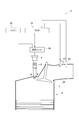
- the ignition device 1 of this embodiment will be described with reference to FIGS.
- the ignition device 1 includes an ignition coil 4 having a primary coil 2 and a secondary coil 3, and an ignition plug 5 connected to the secondary coil 3, and is ignited by electromagnetic induction accompanying on / off of energization to the primary coil 2. Energy is supplied to the plug 5 to generate spark discharge in the air-fuel mixture.
- the ignition device 1 is mounted on an internal combustion engine 6 for running a vehicle and ignites an air-fuel mixture in the combustion chamber 7 at a predetermined ignition timing.
- the spark plug 5 has a well-known structure, and includes a center electrode 8 connected to one end of the secondary coil 3 and a ground electrode 9 grounded via a cylinder head or the like of the internal combustion engine 6. Spark discharge is generated between the center electrode 8 and the ground electrode 9 by the energy generated in the next coil 3.
- the internal combustion engine 6 is capable of, for example, lean combustion using gasoline as fuel, and is provided so that a swirling flow of an air-fuel mixture such as a tumble flow or a swirl flow is generated in the combustion chamber 7.
- the ignition device 1 will be described in detail.
- the ignition device 1 includes a first circuit 11, a second circuit 12, and a control unit 13.
- the first circuit 11 causes the spark plug 5 to start spark discharge by turning on and off the energization of the primary coil 2.
- the second circuit 12 energizes the secondary coil 3 by energizing the primary coil 2 in a direction opposite to the energization direction by the first circuit 11 during the spark discharge started by the operation of the first circuit 11. Maintaining the same direction as the start of the operation of one circuit 11, the energy is continuously supplied to the spark plug 5, and the spark discharge is continued.
- the control unit 13 is a part that controls the operation of the first and second circuits 11 and 12, and includes an electronic control unit (hereinafter referred to as ECU) 16, an input driver 17, and the like.
- ECU electronice control unit
- the ECU 16 is the center of control for the internal combustion engine 6, and outputs various signals such as an ignition signal IGt and a discharge continuation signal IGw, which will be described later, to control energization to the primary coil 2 and to the primary coil 2.
- the electric energy induced in the secondary coil 3 is controlled by controlling the energization of the spark plug 5 to control the spark discharge of the spark plug 5.
- the ECU 16 receives signals from various sensors that are mounted on the vehicle and detect parameters indicating the operating state and control state of the internal combustion engine 6.
- the ECU 16 stores an input circuit that processes an input signal, a CPU that performs control processing and arithmetic processing related to the control of the internal combustion engine 6 based on the input signal, and data and programs necessary for control of the internal combustion engine 6. And an output circuit for outputting signals necessary for controlling the internal combustion engine 6 based on the processing results of the CPU and the CPU.
- the various sensors that output a signal to the ECU 16 include, for example, a rotation speed sensor 24 that detects the rotation speed of the internal combustion engine 6, an intake pressure sensor 25 that detects the pressure of intake air sucked into the internal combustion engine 6, and an air-fuel mixture An air-fuel ratio sensor 26 for detecting the air-fuel ratio of the engine.
- the ECU 16 executes ignition control by the ignition device 1, fuel injection control by the fuel injection valve 27, and the like based on detected values of parameters obtained from these sensors.
- the fuel injection valve 27 is provided in the intake passage 28, but a so-called direct injection type structure in which fuel is directly injected into the combustion chamber 7 may be employed.
- the first circuit 11 has a first switch 31 for starting discharge disposed on the ground side (low potential side) of the other terminal of the primary coil 2.
- the first switch 31 connects the positive electrode of the battery 30 to one terminal of the primary coil 2 and connects the other terminal of the primary coil 2 to the ground.
- the first circuit 11 causes the primary coil 2 to store energy when the first switch 31 is turned on and off, and also uses the energy stored in the primary coil 2 to generate a high voltage in the secondary coil 3 so that the ignition plug 5 starts spark discharge.
- the spark discharge generated by the operation of the first circuit 11 may be referred to as main ignition.
- the energizing direction of the primary coil 2 (that is, the direction of the primary current) is positive in the direction from the battery 30 toward the first switch 31.
- the first circuit 11 turns on the first switch 31 during a period when the ignition signal IGt is given from the ECU 16, thereby applying the voltage of the battery 30 to the primary coil 2 to generate a positive primary current. Energize to cause the primary coil 2 to store magnetic energy. Thereafter, when the first switch 31 is turned off, the first circuit 11 generates a high voltage in the secondary coil 3 by electromagnetic induction to cause main ignition.
- the first switch 31 is an IGBT, a MOS transistor, a thyristor, or the like.
- the ignition signal IGt is a signal for instructing a period during which energy is stored in the primary coil 2 in the first circuit 11 and an ignition start timing.
- the second circuit 12 includes a second switch 34 that is disposed between the primary coil 2 and the first switch 31 and turns on / off the power supply from the booster circuit 33 to the primary coil 2.
- the booster circuit 33 boosts the voltage of the battery 30 and stores it in the capacitor 36 during a period when the ignition signal IGt is given from the ECU 16.
- the booster circuit 33 includes a capacitor 36, a choke coil 37, a boost switch 38, a boost driver 39, and a diode 40.
- One end of the choke coil 37 is connected to the positive electrode of the battery 30, and the energization state of the choke coil 37 is interrupted by the boost switch 38.
- the boost driver 39 gives a control signal to the boost switch 38 to turn the boost switch 38 on and off.
- the boost switch 38 is, for example, a MOS transistor.
- the capacitor 36 stores the magnetic energy generated in the choke coil 37 as electrical energy by the on / off operation of the boost switch 38.
- the booster driver 39 is provided so as to repeatedly turn on and off the booster switch 38 at a predetermined period during a period when the ignition signal IGt is given from the ECU 16.
- the diode 40 prevents the energy stored in the capacitor 36 from flowing back to the choke coil 37 side.
- the second circuit 12 includes a diode 44 in addition to the second switch 34.
- the second switch 34 is, for example, a MOS transistor, and turns on / off the input of energy stored in the capacitor 36 from the negative side of the primary coil 2.
- the diode 44 prevents reverse current flow from the primary coil 2 to the second switch 34 side.
- the second switch 34 is turned on by a control signal supplied from the making driver 17, and thereby inputs energy from the booster circuit 33 to the negative side of the primary coil 2.
- the input driver 17 controls the energy supplied to the primary coil 2 from the capacitor 36 by turning on and off the second switch 34 during the period in which the discharge continuation signal IGw is given. Control the secondary current.
- the discharge continuation signal IGw is a signal for instructing a period for continuing the spark discharge generated as the main ignition.
- the second circuit 12 energizes the primary coil 2 in a direction opposite to the energization direction by the first circuit 11 during the spark discharge started by the operation of the first circuit 11, thereby generating the secondary current in the first circuit. 11 is maintained in the same direction as started by the operation of No. 11, and energy is continuously supplied to the spark plug 5 to continue the spark discharge.
- the spark discharge that continues to the main ignition by the operation of the second circuit 12 may be referred to as a continuous spark discharge.
- the input driver 17 controls the secondary current based on the current command signal IGa which is a signal indicating the command value of the secondary current supplied from the ECU 16.
- One end of the secondary coil 3 is connected to the center electrode 8 of the spark plug 5 as described above, and the other end of the secondary coil 3 detects a secondary current generated in the secondary coil 3 and feeds it back to the control unit 13.
- the other end of the secondary coil 3 is connected to the F / B circuit 46 via a diode 47 that limits the direction of the secondary current to one direction.
- the F / B circuit 46 is connected to a shunt resistor 48 for detecting a secondary current.
- the input driver 17 controls on / off of the second switch 34 based on the detected value of the secondary current fed back and the command value of the secondary current detected based on the current command signal IGa.
- the input driver 17 sets, for example, upper and lower thresholds for the detected value of the secondary current based on the command value, and starts outputting a control signal according to the comparison result between the detected value and the upper and lower thresholds, Or stop. More specifically, the input driver 17 stops outputting the control signal when the detected value of the secondary current becomes larger than the upper limit, and starts outputting the control signal when the detected value of the secondary current becomes smaller than the lower limit. To do.
- the first and second circuits 11 and 12, the F / B circuit 46, and the input driver 17 are grouped together as a circuit unit 49.
- the ignition plug 5, the ignition coil 4, and the circuit unit 49 are installed in each cylinder.
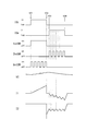
- IGt represents the input state of the ignition signal IGt as high / low
- IGw represents the input state of the discharge continuation signal IGw as high / low
- 1stSW represents the on / off state of the first switch 31
- 2ndSW represents the on / off state of the second switch 34
- BstSW represents the on / off state of the boost switch 38
- VC represents the capacitor 36.
- I1” represents a primary current (a current value flowing through the primary coil 2)
- I2 represents a secondary current (a current value flowing through the secondary coil 3).
- the first switch 31 When the ignition signal IGt switches from low to high (see time t01), during the period when the ignition signal IGt is high, the first switch 31 is maintained in an on state, and a positive primary current flows, and energy is supplied to the primary coil 2. Is stored. While the charging voltage of the capacitor 36 is below a predetermined value, the boost switch 38 is repeatedly turned on and off, and the boosted energy is stored in the capacitor 36.
- the first switch 31 When the ignition signal IGt switches from high to low (see time t02), the first switch 31 is turned off and the primary coil 2 is de-energized. Thereby, a high voltage is generated in the secondary coil 3 by electromagnetic induction, and main ignition is generated in the spark plug 5. After the main ignition is generated in the spark plug 5, the secondary current attenuates in a substantially triangular wave shape (see the dotted line I2). Then, the discharge continuation signal IGw switches from low to high before the secondary current reaches the lower limit threshold (see time t03).
- the second switch 34 When the discharge continuation signal IGw switches from low to high, the second switch 34 is controlled to be turned on / off, and the energy stored in the capacitor 36 is sequentially input to the negative side of the primary coil 2 so that the primary current is 1 It flows from the secondary coil 2 toward the positive pole of the battery 30. Specifically, each time the second switch 34 is turned on, a primary current from the primary coil 2 toward the positive pole of the battery 30 is added, and the primary current increases to the negative side (time t03 to t04). reference).
- the ignition device 1 further includes a humidity detection unit (hereinafter referred to as a humidity sensor 50).
- the humidity sensor 50 is provided in the intake passage 28 that guides the intake air to the internal combustion engine 6, detects the humidity of the intake air, and outputs a signal corresponding to the humidity of the intake air to the ECU 16 (see FIG. 2).
- the control unit 13 Based on the humidity detection value of the humidity sensor 50, the control unit 13 selects two modes for controlling the start timing of spark discharge by the first circuit 11 and the amount of energy input to the spark plug 5 by the second circuit 12. Use properly.
- One mode is a mode corresponding to a normal state, in which the start timing of spark discharge by the first circuit 11 is set as a predetermined time, and the amount of energy input to the spark plug 5 by the second circuit 12 is set as a predetermined amount (hereinafter referred to as a mode). Is called the normal mode).
- the other mode is a mode corresponding to a high humidity state.
- the start timing of the spark discharge by the first circuit 11 is advanced from the normal mode, and the amount of energy input to the spark plug 5 by the second circuit 12 is increased from the normal mode.
- Mode hereinafter referred to as high humidity mode.
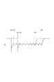
- the solid line represents the time change of the secondary current in the high humidity mode
- the dotted line represents the time change of the secondary current in the normal mode.
- the command value of the secondary current is set equal in both the high humidity mode and the normal mode.
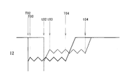
- T02, T03, and T04 represent the signal switching time in the high humidity mode
- t02, t03, and t04 represent the signal switching time in the low humidity mode.
- T02 represents the time when the ignition signal IGt switches from high to low, and corresponds to t02 in FIG.
- T03 represents the time for the discharge continuation signal IGw to switch from low to high
- T04 represents the time for the discharge continuation signal IGw to switch from high to low, and corresponds to t04 in FIG.
- t02 represents the time when the ignition signal IGt switches from high to low
- t03 represents the time for the discharge continuation signal IGw to switch from low to high
- t04 represents the time for the discharge continuation signal IGw to switch from high to low, and corresponds to t04 in FIG.
- control unit 13 determines whether the state of the intake air is a high humidity state from the detection value of the humidity sensor 50. Whether or not the humidity state is high is determined by whether or not the detection value of the humidity sensor 50 exceeds a preset threshold value.
- the control unit 13 executes the high humidity mode.
- the high humidity mode is executed, the ignition device 1 starts spark discharge earlier than the normal mode (see time T02 and time t02), and the amount of energy input to the spark plug 5 increases from the normal mode. Since the command value of the secondary current is set equal in the high humidity mode and the normal mode, the increase in energy input is realized by extending the discharge duration (time T03 to T04, time t03 to t04). reference).
- the control unit 13 executes the normal mode.
- the control unit 13 advances the start timing of the spark discharge by the first circuit 11 and increases the energy to the spark plug 5 by the second circuit 12 as the humidity of the intake air increases. Increase the amount of input.
- the control unit 13 increases the amount of energy input by controlling the operation of the second circuit 12 and extending the discharge duration. Thereby, the amount of energy input to the spark plug 5 can be increased without increasing the magnitude of the secondary current.
- the period of continuous spark discharge can be expanded and contracted without increasing the magnitude of the secondary current by expanding and contracting the period of increasing the primary current to the minus side.
- the secondary current in an ignition device that does not have the second circuit, when the discharge period is extended, the secondary current must be increased to cope with it, and the consumption of the spark plug inevitably increases. For this reason, compared with the ignition device which does not have a 2nd circuit, the ignition device 1 of the said Example can increase energy input, suppressing consumption of the spark plug 5.
- the duration of the continuous spark discharge can be shortened, so that it is possible to quickly prepare for the next ignition.
- the command value of the secondary current may be set large.
- the amount of energy input to the spark plug 5 may be increased by increasing the magnitude of the secondary current and increasing the duration of the continuous spark discharge.
- the high humidity mode and the normal mode are switched by the threshold determination, but the start timing of the spark discharge is advanced in proportion to the humidity detected value by the humidity sensor 14 and the energy to the spark plug 5 is increased.
- the input amount may be increased.
Landscapes
- Engineering & Computer Science (AREA)
- Chemical & Material Sciences (AREA)
- Combustion & Propulsion (AREA)
- Mechanical Engineering (AREA)
- General Engineering & Computer Science (AREA)
- Signal Processing (AREA)
- Ignition Installations For Internal Combustion Engines (AREA)
Priority Applications (2)
| Application Number | Priority Date | Filing Date | Title |
|---|---|---|---|
| US15/753,227 US10138861B2 (en) | 2015-08-19 | 2016-07-26 | Ignition device |
| DE112016003762.7T DE112016003762T8 (de) | 2015-08-19 | 2016-07-26 | Zündvorrichtung |
Applications Claiming Priority (2)
| Application Number | Priority Date | Filing Date | Title |
|---|---|---|---|
| JP2015162346A JP6622513B2 (ja) | 2015-08-19 | 2015-08-19 | 点火装置 |
| JP2015-162346 | 2015-08-19 |
Publications (1)
| Publication Number | Publication Date |
|---|---|
| WO2017029951A1 true WO2017029951A1 (ja) | 2017-02-23 |
Family
ID=58052203
Family Applications (1)
| Application Number | Title | Priority Date | Filing Date |
|---|---|---|---|
| PCT/JP2016/071822 Ceased WO2017029951A1 (ja) | 2015-08-19 | 2016-07-26 | 点火装置 |
Country Status (4)
| Country | Link |
|---|---|
| US (1) | US10138861B2 (enExample) |
| JP (1) | JP6622513B2 (enExample) |
| DE (1) | DE112016003762T8 (enExample) |
| WO (1) | WO2017029951A1 (enExample) |
Families Citing this family (2)
| Publication number | Priority date | Publication date | Assignee | Title |
|---|---|---|---|---|
| JP6987035B2 (ja) * | 2018-09-27 | 2021-12-22 | 日立Astemo株式会社 | 電磁弁駆動装置 |
| JP2023179015A (ja) * | 2022-06-07 | 2023-12-19 | ダイヤゼブラ電機株式会社 | 点火装置 |
Citations (3)
| Publication number | Priority date | Publication date | Assignee | Title |
|---|---|---|---|---|
| JP2013036892A (ja) * | 2011-08-09 | 2013-02-21 | Denso Corp | 空気流量測定装置 |
| JP2015113730A (ja) * | 2013-12-10 | 2015-06-22 | 株式会社日本自動車部品総合研究所 | 点火装置 |
| JP2016037880A (ja) * | 2014-08-06 | 2016-03-22 | スズキ株式会社 | 点火制御装置 |
Family Cites Families (5)
| Publication number | Priority date | Publication date | Assignee | Title |
|---|---|---|---|---|
| JPS58155277A (ja) * | 1982-03-11 | 1983-09-14 | Mazda Motor Corp | エンジンの点火時期制御装置 |
| JPH06272590A (ja) | 1993-03-22 | 1994-09-27 | Yanmar Diesel Engine Co Ltd | 火花点火式希薄燃焼内燃機関の空燃比制御装置 |
| SE527259C2 (sv) * | 2004-06-22 | 2006-01-31 | Mecel Ab | Metod och anordning för att styra strömmen i ett tändstift |
| US7966992B2 (en) * | 2009-02-15 | 2011-06-28 | Ford Global Technologies, Llc | Combustion control using ion sense feedback and multi-strike spark to manage high dilution and lean AFR |
| JP6354710B2 (ja) * | 2015-09-01 | 2018-07-11 | トヨタ自動車株式会社 | 内燃機関の制御装置 |
-
2015
- 2015-08-19 JP JP2015162346A patent/JP6622513B2/ja not_active Expired - Fee Related
-
2016
- 2016-07-26 WO PCT/JP2016/071822 patent/WO2017029951A1/ja not_active Ceased
- 2016-07-26 US US15/753,227 patent/US10138861B2/en active Active
- 2016-07-26 DE DE112016003762.7T patent/DE112016003762T8/de not_active Ceased
Patent Citations (3)
| Publication number | Priority date | Publication date | Assignee | Title |
|---|---|---|---|---|
| JP2013036892A (ja) * | 2011-08-09 | 2013-02-21 | Denso Corp | 空気流量測定装置 |
| JP2015113730A (ja) * | 2013-12-10 | 2015-06-22 | 株式会社日本自動車部品総合研究所 | 点火装置 |
| JP2016037880A (ja) * | 2014-08-06 | 2016-03-22 | スズキ株式会社 | 点火制御装置 |
Also Published As
| Publication number | Publication date |
|---|---|
| DE112016003762T8 (de) | 2018-06-28 |
| JP2017040204A (ja) | 2017-02-23 |
| US20180245562A1 (en) | 2018-08-30 |
| DE112016003762T5 (de) | 2018-05-03 |
| US10138861B2 (en) | 2018-11-27 |
| JP6622513B2 (ja) | 2019-12-18 |
Similar Documents
| Publication | Publication Date | Title |
|---|---|---|
| CN106170623B (zh) | 内燃机用点火装置 | |
| WO2015156371A1 (ja) | 制御装置及び点火装置 | |
| JP2017036694A (ja) | 点火装置 | |
| JP6549901B2 (ja) | 点火装置 | |
| JP6337584B2 (ja) | 点火装置 | |
| JP6609111B2 (ja) | 点火装置 | |
| JP6392535B2 (ja) | 内燃機関の制御装置 | |
| JP6622513B2 (ja) | 点火装置 | |
| JP6349895B2 (ja) | 内燃機関用点火装置 | |
| JP6627644B2 (ja) | 点火制御装置 | |
| JP6264166B2 (ja) | 点火装置の故障診断装置、および、点火装置の故障診断方法 | |
| JP2017048701A (ja) | 点火装置 | |
| JP6297899B2 (ja) | 点火装置 | |
| JP6398272B2 (ja) | 点火装置 | |
| JP6489255B2 (ja) | 内燃機関用点火装置 | |
| JP6531841B2 (ja) | 点火装置 | |
| JP6331614B2 (ja) | 点火制御装置 | |
| JP6330440B2 (ja) | 点火制御装置 | |
| JP6265016B2 (ja) | 点火装置 | |
| JP6604265B2 (ja) | 点火制御装置 | |
| JP6331618B2 (ja) | 内燃機関用点火装置 | |
| JP6349894B2 (ja) | 点火制御装置 | |
| JP2015200259A (ja) | 点火制御装置 |
Legal Events
| Date | Code | Title | Description |
|---|---|---|---|
| 121 | Ep: the epo has been informed by wipo that ep was designated in this application |
Ref document number: 16836942 Country of ref document: EP Kind code of ref document: A1 |
|
| WWE | Wipo information: entry into national phase |
Ref document number: 15753227 Country of ref document: US |
|
| WWE | Wipo information: entry into national phase |
Ref document number: 112016003762 Country of ref document: DE |
|
| 122 | Ep: pct application non-entry in european phase |
Ref document number: 16836942 Country of ref document: EP Kind code of ref document: A1 |