WO2017029862A1 - 基板処理方法および基板処理装置 - Google Patents
基板処理方法および基板処理装置 Download PDFInfo
- Publication number
- WO2017029862A1 WO2017029862A1 PCT/JP2016/066955 JP2016066955W WO2017029862A1 WO 2017029862 A1 WO2017029862 A1 WO 2017029862A1 JP 2016066955 W JP2016066955 W JP 2016066955W WO 2017029862 A1 WO2017029862 A1 WO 2017029862A1
- Authority
- WO
- WIPO (PCT)
- Prior art keywords
- liquid
- substrate
- liquid film
- water
- mixed
- Prior art date
- Legal status (The legal status is an assumption and is not a legal conclusion. Google has not performed a legal analysis and makes no representation as to the accuracy of the status listed.)
- Ceased
Links
Images











Classifications
-
- H—ELECTRICITY
- H10—SEMICONDUCTOR DEVICES; ELECTRIC SOLID-STATE DEVICES NOT OTHERWISE PROVIDED FOR
- H10P—GENERIC PROCESSES OR APPARATUS FOR THE MANUFACTURE OR TREATMENT OF DEVICES COVERED BY CLASS H10
- H10P72/00—Handling or holding of wafers, substrates or devices during manufacture or treatment thereof
- H10P72/04—Apparatus for manufacture or treatment
- H10P72/0402—Apparatus for fluid treatment
- H10P72/0404—Apparatus for fluid treatment for general liquid treatment, e.g. etching followed by cleaning
-
- B—PERFORMING OPERATIONS; TRANSPORTING
- B08—CLEANING
- B08B—CLEANING IN GENERAL; PREVENTION OF FOULING IN GENERAL
- B08B3/00—Cleaning by methods involving the use or presence of liquid or steam
- B08B3/04—Cleaning involving contact with liquid
- B08B3/041—Cleaning travelling work
-
- B—PERFORMING OPERATIONS; TRANSPORTING
- B08—CLEANING
- B08B—CLEANING IN GENERAL; PREVENTION OF FOULING IN GENERAL
- B08B3/00—Cleaning by methods involving the use or presence of liquid or steam
- B08B3/04—Cleaning involving contact with liquid
- B08B3/08—Cleaning involving contact with liquid the liquid having chemical or dissolving effect
-
- B—PERFORMING OPERATIONS; TRANSPORTING
- B08—CLEANING
- B08B—CLEANING IN GENERAL; PREVENTION OF FOULING IN GENERAL
- B08B3/00—Cleaning by methods involving the use or presence of liquid or steam
- B08B3/04—Cleaning involving contact with liquid
- B08B3/10—Cleaning involving contact with liquid with additional treatment of the liquid or of the object being cleaned, e.g. by heat, by electricity or by vibration
-
- B—PERFORMING OPERATIONS; TRANSPORTING
- B08—CLEANING
- B08B—CLEANING IN GENERAL; PREVENTION OF FOULING IN GENERAL
- B08B5/00—Cleaning by methods involving the use of air flow or gas flow
- B08B5/02—Cleaning by the force of jets, e.g. blowing-out cavities
-
- B—PERFORMING OPERATIONS; TRANSPORTING
- B08—CLEANING
- B08B—CLEANING IN GENERAL; PREVENTION OF FOULING IN GENERAL
- B08B5/00—Cleaning by methods involving the use of air flow or gas flow
- B08B5/02—Cleaning by the force of jets, e.g. blowing-out cavities
- B08B5/023—Cleaning travelling work
-
- H—ELECTRICITY
- H10—SEMICONDUCTOR DEVICES; ELECTRIC SOLID-STATE DEVICES NOT OTHERWISE PROVIDED FOR
- H10P—GENERIC PROCESSES OR APPARATUS FOR THE MANUFACTURE OR TREATMENT OF DEVICES COVERED BY CLASS H10
- H10P14/00—Formation of materials, e.g. in the shape of layers or pillars
- H10P14/60—Formation of materials, e.g. in the shape of layers or pillars of insulating materials
- H10P14/65—Formation of materials, e.g. in the shape of layers or pillars of insulating materials characterised by treatments performed before or after the formation of the materials
- H10P14/6516—Formation of materials, e.g. in the shape of layers or pillars of insulating materials characterised by treatments performed before or after the formation of the materials of treatments performed after formation of the materials
- H10P14/6534—Formation of materials, e.g. in the shape of layers or pillars of insulating materials characterised by treatments performed before or after the formation of the materials of treatments performed after formation of the materials by exposure to a liquid
-
- H—ELECTRICITY
- H10—SEMICONDUCTOR DEVICES; ELECTRIC SOLID-STATE DEVICES NOT OTHERWISE PROVIDED FOR
- H10P—GENERIC PROCESSES OR APPARATUS FOR THE MANUFACTURE OR TREATMENT OF DEVICES COVERED BY CLASS H10
- H10P70/00—Cleaning of wafers, substrates or parts of devices
- H10P70/10—Cleaning before device manufacture, i.e. Begin-Of-Line process
- H10P70/15—Cleaning before device manufacture, i.e. Begin-Of-Line process by wet cleaning only
-
- H—ELECTRICITY
- H10—SEMICONDUCTOR DEVICES; ELECTRIC SOLID-STATE DEVICES NOT OTHERWISE PROVIDED FOR
- H10P—GENERIC PROCESSES OR APPARATUS FOR THE MANUFACTURE OR TREATMENT OF DEVICES COVERED BY CLASS H10
- H10P72/00—Handling or holding of wafers, substrates or devices during manufacture or treatment thereof
- H10P72/04—Apparatus for manufacture or treatment
- H10P72/0402—Apparatus for fluid treatment
- H10P72/0406—Apparatus for fluid treatment for cleaning followed by drying, rinsing, stripping, blasting or the like
-
- H—ELECTRICITY
- H10—SEMICONDUCTOR DEVICES; ELECTRIC SOLID-STATE DEVICES NOT OTHERWISE PROVIDED FOR
- H10P—GENERIC PROCESSES OR APPARATUS FOR THE MANUFACTURE OR TREATMENT OF DEVICES COVERED BY CLASS H10
- H10P72/00—Handling or holding of wafers, substrates or devices during manufacture or treatment thereof
- H10P72/04—Apparatus for manufacture or treatment
- H10P72/0402—Apparatus for fluid treatment
- H10P72/0406—Apparatus for fluid treatment for cleaning followed by drying, rinsing, stripping, blasting or the like
- H10P72/0408—Apparatus for fluid treatment for cleaning followed by drying, rinsing, stripping, blasting or the like for drying
-
- H—ELECTRICITY
- H10—SEMICONDUCTOR DEVICES; ELECTRIC SOLID-STATE DEVICES NOT OTHERWISE PROVIDED FOR
- H10P—GENERIC PROCESSES OR APPARATUS FOR THE MANUFACTURE OR TREATMENT OF DEVICES COVERED BY CLASS H10
- H10P72/00—Handling or holding of wafers, substrates or devices during manufacture or treatment thereof
- H10P72/04—Apparatus for manufacture or treatment
- H10P72/0402—Apparatus for fluid treatment
- H10P72/0406—Apparatus for fluid treatment for cleaning followed by drying, rinsing, stripping, blasting or the like
- H10P72/0411—Apparatus for fluid treatment for cleaning followed by drying, rinsing, stripping, blasting or the like for wet cleaning or washing
-
- H—ELECTRICITY
- H10—SEMICONDUCTOR DEVICES; ELECTRIC SOLID-STATE DEVICES NOT OTHERWISE PROVIDED FOR
- H10P—GENERIC PROCESSES OR APPARATUS FOR THE MANUFACTURE OR TREATMENT OF DEVICES COVERED BY CLASS H10
- H10P72/00—Handling or holding of wafers, substrates or devices during manufacture or treatment thereof
- H10P72/04—Apparatus for manufacture or treatment
- H10P72/0402—Apparatus for fluid treatment
- H10P72/0406—Apparatus for fluid treatment for cleaning followed by drying, rinsing, stripping, blasting or the like
- H10P72/0411—Apparatus for fluid treatment for cleaning followed by drying, rinsing, stripping, blasting or the like for wet cleaning or washing
- H10P72/0414—Apparatus for fluid treatment for cleaning followed by drying, rinsing, stripping, blasting or the like for wet cleaning or washing using mainly spraying means, e.g. nozzles
-
- H—ELECTRICITY
- H10—SEMICONDUCTOR DEVICES; ELECTRIC SOLID-STATE DEVICES NOT OTHERWISE PROVIDED FOR
- H10P—GENERIC PROCESSES OR APPARATUS FOR THE MANUFACTURE OR TREATMENT OF DEVICES COVERED BY CLASS H10
- H10P72/00—Handling or holding of wafers, substrates or devices during manufacture or treatment thereof
- H10P72/04—Apparatus for manufacture or treatment
- H10P72/0402—Apparatus for fluid treatment
- H10P72/0406—Apparatus for fluid treatment for cleaning followed by drying, rinsing, stripping, blasting or the like
- H10P72/0411—Apparatus for fluid treatment for cleaning followed by drying, rinsing, stripping, blasting or the like for wet cleaning or washing
- H10P72/0416—Apparatus for fluid treatment for cleaning followed by drying, rinsing, stripping, blasting or the like for wet cleaning or washing with the semiconductor substrates being dipped in baths or vessels
-
- H—ELECTRICITY
- H10—SEMICONDUCTOR DEVICES; ELECTRIC SOLID-STATE DEVICES NOT OTHERWISE PROVIDED FOR
- H10P—GENERIC PROCESSES OR APPARATUS FOR THE MANUFACTURE OR TREATMENT OF DEVICES COVERED BY CLASS H10
- H10P72/00—Handling or holding of wafers, substrates or devices during manufacture or treatment thereof
- H10P72/04—Apparatus for manufacture or treatment
- H10P72/0431—Apparatus for thermal treatment
-
- H—ELECTRICITY
- H10—SEMICONDUCTOR DEVICES; ELECTRIC SOLID-STATE DEVICES NOT OTHERWISE PROVIDED FOR
- H10P—GENERIC PROCESSES OR APPARATUS FOR THE MANUFACTURE OR TREATMENT OF DEVICES COVERED BY CLASS H10
- H10P72/00—Handling or holding of wafers, substrates or devices during manufacture or treatment thereof
- H10P72/04—Apparatus for manufacture or treatment
- H10P72/0448—Apparatus for applying a liquid, a resin, an ink or the like
-
- B—PERFORMING OPERATIONS; TRANSPORTING
- B08—CLEANING
- B08B—CLEANING IN GENERAL; PREVENTION OF FOULING IN GENERAL
- B08B2203/00—Details of cleaning machines or methods involving the use or presence of liquid or steam
- B08B2203/007—Heating the liquid
-
- B—PERFORMING OPERATIONS; TRANSPORTING
- B08—CLEANING
- B08B—CLEANING IN GENERAL; PREVENTION OF FOULING IN GENERAL
- B08B3/00—Cleaning by methods involving the use or presence of liquid or steam
- B08B3/04—Cleaning involving contact with liquid
- B08B3/10—Cleaning involving contact with liquid with additional treatment of the liquid or of the object being cleaned, e.g. by heat, by electricity or by vibration
- B08B3/106—Cleaning involving contact with liquid with additional treatment of the liquid or of the object being cleaned, e.g. by heat, by electricity or by vibration by boiling the liquid
-
- B—PERFORMING OPERATIONS; TRANSPORTING
- B08—CLEANING
- B08B—CLEANING IN GENERAL; PREVENTION OF FOULING IN GENERAL
- B08B7/00—Cleaning by methods not provided for in a single other subclass or a single group in this subclass
- B08B7/0064—Cleaning by methods not provided for in a single other subclass or a single group in this subclass by temperature changes
- B08B7/0071—Cleaning by methods not provided for in a single other subclass or a single group in this subclass by temperature changes by heating
Definitions
- the present invention relates to a substrate processing method and a substrate processing apparatus for processing a surface of a substrate using a processing liquid.
- substrates to be processed include semiconductor wafers, liquid crystal display substrates, plasma display substrates, FED (Field Emission Display) substrates, optical disk substrates, magnetic disk substrates, magneto-optical disk substrates, and photomasks.
- substrate, ceramic substrate, solar cell substrate and the like are examples of substrates to be processed.
- a single-wafer type substrate processing apparatus that processes substrates one by one supplies a processing liquid to a spin chuck that rotates the substrate while holding the substrate substantially horizontal, and a surface of the substrate that is rotated by the spin chuck. And a nozzle for the purpose.
- a chemical solution is supplied to the substrate held by the spin chuck (chemical solution processing). Thereafter, water is supplied to the substrate, whereby the chemical solution on the substrate is replaced with water (rinsing treatment). Thereafter, a spin dry process for removing water on the substrate is performed (see Patent Document 1 and Patent Document 2).
- a spin dry process for removing water on the substrate is performed (see Patent Document 1 and Patent Document 2).
- the spin dry process when the substrate is rotated at a high speed, water adhering to the substrate is shaken off and removed (dried). Common water is deionized water.
- IPA isopropyl alcohol
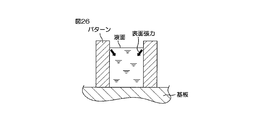
- a liquid surface (an interface between air and liquid) is formed in the pattern.
- the surface tension of the liquid acts at the contact position between the liquid surface and the pattern. This surface tension is one of the causes that cause the pattern to collapse.
- organic solvent a liquid of an organic solvent (hereinafter simply referred to as “organic solvent”) is supplied to the surface of the substrate before the spin drying step after the rinsing process, the organic solvent enters between the patterns.
- the surface tension of organic solvents is lower than that of typical water. This alleviates the problem of pattern collapse due to surface tension.
- the water on the substrate may contain particles.
- the particles contained in the water reattach to the upper surface of the substrate, and as a result, There is a possibility that particles are generated on the surface (surface to be processed) of the substrate.
- the low surface tension liquid organic solvent
- the replacement performance with respect to the treatment liquid water is not so high. Therefore, it takes a long time to completely replace the treatment liquid on the surface of the substrate with the low surface tension liquid only by supplying the low surface tension liquid. As a result of the long time required for the replacement with the low surface tension liquid, the drying time of the surface of the substrate may be prolonged.
- one of the objects of the present invention is to provide a substrate processing method and a substrate processing apparatus that can dry the surface of the substrate while suppressing or preventing the generation of particles.
- the object of the present invention is to completely replace the treatment liquid on the surface of the substrate with a low surface tension liquid in a short time, whereby the surface of the substrate can be dried in a short time while suppressing the collapse of the pattern.
- a processing method and a substrate processing apparatus are provided.
- a substrate processing method for processing a surface of a substrate using a processing liquid, wherein the processing liquid adhering to the surface of the substrate is treated with the first liquid and the first liquid.
- the treatment liquid on the surface of the substrate is replaced with the mixed liquid, and the mixed liquid comes into contact with the surface of the substrate.
- the liquid removal region expands while the liquid mixture evaporates at the gas-solid interface of the liquid mixture.
- the first liquid having a relatively low boiling point is mainly evaporated, and as a result, the concentration of the second liquid having a relatively high boiling point and a low surface tension is increased.
- the concentration gradient such that the concentration of the second liquid increases as it approaches the gas-solid liquid interface. It is formed. Due to the concentration difference of the second liquid, Marangoni convection that flows in a direction away from the gas-solid liquid interface is generated in the vicinity of the interface of the mixed liquid.
- the method further includes a substrate holding step of holding the substrate horizontally, and the liquid mixture replacement step includes a liquid film forming step of forming a liquid film of the liquid mixture covering the upper surface of the substrate.
- the liquid film removal region forming step of forming a liquid film removal region in the liquid film of the liquid mixture, and the liquid film removal for expanding the liquid film removal region toward the outer periphery of the substrate. And an area expansion process.
- a liquid film of the mixed liquid is formed on the upper surface of the substrate held in a horizontal posture.
- a liquid film removal region is formed in the liquid film of the mixed liquid, and is further expanded until the liquid film removal region covers the entire substrate.
- the liquid film removal area expands while the liquid mixture evaporates at the gas-solid interface of the liquid film of the liquid mixture.
- the first liquid having a relatively low boiling point is mainly evaporated, and as a result, the concentration of the second liquid having a relatively high boiling point and a low surface tension is increased. Therefore, a concentration gradient is formed in the vicinity of the interface of the liquid film of the mixed liquid such that the concentration of the second liquid increases as the gas-solid interface is approached. Due to the concentration difference of the second liquid, Marangoni convection that flows in a direction away from the gas-solid interface is generated in the vicinity of the interface of the liquid film of the mixed liquid. Marangoni convection continues to occur after the formation of the liquid film removal region until the liquid film removal region covers the entire substrate.
- the particles contained in the vicinity of the interface of the liquid film of the mixed solution are subjected to Marangoni convection and move in a direction away from the gas-solid interface. Therefore, the particles are taken into the liquid film of the mixed liquid.
- the liquid film removal area expands, the gas-liquid interface moves toward the outside in the radial direction of the substrate, but the liquid film removal area expands while particles are taken into the liquid film bulk of the mixed liquid. .
- a particle is discharged
- the method may further include a paddle step of making the substrate stationary or rotating the substrate at a paddle speed around the rotation axis in parallel with the liquid film forming step.
- the paddle process is executed in parallel with the liquid film forming process, the thickness of the portion near the interface of the liquid film formed on the upper surface of the substrate can be kept thick. Since the thickness in the vicinity of the interface of the liquid film of the mixed liquid is large, Marangoni convection can be stably generated in the vicinity of the interface.
- the liquid film removal region forming step may include a gas blowing step of blowing a gas onto the upper surface of the substrate.
- the gas may contain a high temperature gas higher than normal temperature.
- the evaporation of the first liquid at the gas-solid liquid interface of the liquid film of the mixed liquid can be promoted by supplying the high temperature gas to the upper surface of the substrate.
- the concentration gradient of the second liquid in the vicinity of the interface of the liquid film of the mixed liquid can be made abrupt. Therefore, Marangoni convection generated in the vicinity of the interface of the liquid film of the mixed liquid can be further enhanced. it can.
- the liquid film removal region large process may include a high-speed rotation process in which the substrate is rotated at a higher speed than during the liquid film formation process.
- the liquid film removal region can be expanded by the strong centrifugal force generated by rotating the substrate at a high speed.
- the first liquid may contain water, and the second liquid may contain ethylene glycol (hereinafter referred to as “EG”).
- EG ethylene glycol
- the treatment liquid on the surface of the substrate is replaced with the mixed liquid, and the mixed liquid comes into contact with the surface of the substrate.
- the liquid removal region expands while the liquid mixture evaporates at the gas-solid interface of the liquid mixture.
- water having a relatively low boiling point mainly evaporates.
- the concentration of EG having a relatively high boiling point and a low surface tension increases. Therefore, a concentration gradient is formed in the portion of the mixed liquid near the gas-liquid interface (hereinafter referred to as “interface vicinity” in this section) so that the concentration of EG increases as the gas-liquid interface is approached.
- face vicinity the concentration of EG increases as the gas-liquid interface is approached. Due to such a difference in EG concentration, Marangoni convection that flows in a direction away from the gas-solid liquid interface is generated in the vicinity of the interface of the mixed liquid.
- a substrate holding unit for horizontally holding a substrate, a first liquid, and a surface tension higher in boiling point than that in the first liquid and lower than that in the first liquid.
- a liquid mixture supply unit that supplies a liquid mixture with the second liquid to the upper surface of the substrate; and a control device that controls at least the liquid mixture supply unit, wherein the control device covers the upper surface of the substrate.
- a liquid film forming step of forming a liquid film of the liquid, a liquid film removing region forming step of forming a liquid film removing region in the liquid film of the mixed liquid, and the liquid film removing region is expanded toward the outer periphery of the substrate
- a substrate processing apparatus for executing a liquid film removal region expanding step.
- the liquid film of the mixed liquid is formed on the upper surface of the substrate held in the horizontal posture.
- a liquid film removal region is formed in the liquid film of the mixed liquid, and is further expanded until the liquid film removal region covers the entire substrate.
- the liquid film removal area expands while the liquid mixture evaporates at the gas-solid interface of the liquid film of the liquid mixture.
- the first liquid having a relatively low boiling point is mainly evaporated, and as a result, the concentration of the second liquid having a relatively high boiling point and a low surface tension is increased. Therefore, a concentration gradient is formed in the vicinity of the interface of the liquid film of the mixed liquid such that the concentration of the second liquid increases as the gas-solid interface is approached. Due to the concentration difference of the second liquid, Marangoni convection that flows in a direction away from the gas-solid interface is generated in the vicinity of the interface of the liquid film of the mixed liquid. Marangoni convection continues to occur after the formation of the liquid film removal region until the liquid film removal region covers the entire substrate.
- the particles contained in the vicinity of the interface of the liquid film of the mixed solution are subjected to Marangoni convection and move in a direction away from the gas-solid interface. Therefore, the particles are taken into the liquid film of the mixed liquid.
- the liquid film removal area expands, the gas-liquid interface moves toward the outside in the radial direction of the substrate, but the liquid film removal area expands while particles are taken into the liquid film bulk of the mixed liquid. .
- a particle is discharged
- a substrate processing method for processing a surface of a substrate using a processing liquid wherein a boiling point of the substrate surface on which the processing liquid remains is higher than that of the processing liquid.
- a liquid mixture forming step of forming a liquid mixture of the residual treatment liquid and the low surface tension liquid on the surface of the substrate by supplying a low surface tension liquid having a surface tension lower than that of the treatment liquid.
- a drying step of removing the low surface tension liquid from the surface of the substrate and drying the surface of the substrate.
- the low surface tension liquid is supplied to the surface of the substrate where the processing liquid remains.
- the treatment liquid and the low surface tension liquid are mixed, and a mixed liquid is formed on the surface of the substrate.
- the process liquid with a low boiling point contained in the liquid mixture evaporates, As a result, the process liquid on the surface of a board
- substrate can be completely substituted with a low surface tension liquid.
- the liquid mixture is formed by supplying the low surface tension liquid and the processing liquid contained in the liquid mixture is evaporated to leave only the low surface tension liquid, the replacement speed of the processing liquid with the low surface tension liquid is increased. Can do. Thereby, the processing liquid on the surface of the substrate can be completely replaced with the low surface tension liquid in a short time. Therefore, the surface of the substrate can be dried in a short time while suppressing the collapse of the pattern.
- the processing liquid remains on the surface of the substrate means that a liquid film of the processing liquid is formed on the surface of the substrate, or there is a droplet of the processing liquid on the surface of the substrate.
- the present invention includes a state in which no liquid film or droplets are present on the surface of the substrate, but the processing liquid has entered the pattern on the surface of the substrate.
- the replacing step includes a mixed solution heating step of heating the mixed solution in order to evaporate the processing solution contained in the mixed solution.
- the low surface tension liquid is supplied to the surface of the substrate where the processing liquid remains.
- the treatment liquid and the low surface tension liquid are mixed, and a mixed liquid is formed on the surface of the substrate.
- a processing liquid with a low boiling point contained in the liquid mixture can be evaporated by heating a liquid mixture. Thereby, the processing liquid on the surface of the substrate can be completely replaced with a low surface tension liquid.
- the method further includes a substrate holding step of holding the substrate horizontally, and the liquid mixture forming step includes a step of forming a liquid film of the liquid mixture covering an upper surface of the substrate, and the liquid mixture heating step And a step of heating the liquid film of the mixed solution.
- the low surface tension liquid is supplied to the upper surface of the substrate held in a horizontal posture.
- the processing liquid and the low surface tension liquid are mixed, and a liquid film of the mixed liquid is formed on the surface of the substrate.
- the process liquid with a low boiling point contained in the liquid film of the liquid mixture can be evaporated by heating the liquid film of the liquid mixture.
- the treatment liquid in the liquid film can be completely replaced with a low surface tension liquid.
- the mixed liquid may be heated at a predetermined high temperature that is higher than the boiling point of the treatment liquid and lower than the boiling point of the low surface tension liquid.
- the low surface tension liquid in the mixed liquid hardly evaporates.
- the evaporation of the treatment liquid in the mixed liquid is promoted. That is, only the treatment liquid in the mixed liquid can be efficiently evaporated. Thereby, complete replacement with the low surface tension liquid can be realized in a shorter time.
- the liquid film of the low surface tension liquid which has predetermined thickness can also be hold
- the method further includes a substrate holding step of holding the substrate horizontally, the liquid mixture forming step includes a step of forming a liquid film of the liquid mixture covering an upper surface of the substrate, and the replacing step includes the step of A liquid film removal region forming step of forming a liquid film removal region in the liquid film of the mixed liquid, and a liquid film removal region expansion step of expanding the liquid film removal region toward the outer periphery of the substrate may be included.
- a liquid film of the mixed liquid is formed on the upper surface of the substrate held in a horizontal posture.
- a liquid film removal region is formed in the liquid film of the mixed liquid, and is further expanded until the liquid film removal region covers the entire substrate.
- the liquid film removal region expands while the liquid mixture evaporates at the gas-solid interface of the liquid film of the liquid mixture.
- the treatment liquid having a low boiling point is mainly evaporated, and as a result, the concentration of the low surface tension liquid is increased.
- the method may further include a paddle step of bringing the substrate into a stationary state or rotating the substrate at a paddle speed around the rotation axis in parallel with the mixed liquid film forming step.
- the liquid film removal region forming step may include a gas blowing step of blowing a gas onto the upper surface of the substrate.
- the liquid film removal region large process may include a high-speed rotation process in which the substrate is rotated at a higher speed than in the mixed liquid film formation process.
- the liquid film removal region can be expanded by the strong centrifugal force generated by rotating the substrate at a high speed.
- the gas may contain a high temperature gas higher than normal temperature.
- this method it is possible to promote the evaporation of the treatment liquid at the gas-solid liquid interface of the liquid film of the mixed liquid by supplying the high temperature gas to the upper surface of the substrate.
- the concentration gradient of the low surface tension liquid in the vicinity of the interface of the liquid film of the mixed liquid can be made abrupt, and therefore, only the low surface tension liquid can be present at the gas-solid liquid interface.
- the treatment liquid may contain water, and the low surface tension liquid may contain EG.
- EG is supplied to the surface of the substrate where water remains. Thereby, water and EG mix and a liquid mixture is formed on the surface of the substrate. And the water with a low boiling point contained in the liquid mixture mainly evaporates, As a result, the water on the surface of a board
- a mixed solution is formed by supplying EG and water contained in the mixed solution is evaporated to leave only EG, the replacement rate of water with EG can be increased. Thereby, the water on the surface of the substrate can be completely replaced with EG in a short time. Therefore, the surface of the substrate can be dried in a short time while suppressing the collapse of the pattern. Thereby, drying time can be shortened and the usage-amount of an organic solvent can be aimed at.
- EG is supplied to the surface of the substrate where water remains. Thereby, water and EG mix and a liquid mixture is formed on the surface of the substrate. And the water with a low boiling point contained in the liquid mixture evaporates, As a result, the water on the surface of a board
- the replacement rate of water with EG can be increased. Thereby, the water on the surface of the substrate can be completely replaced with EG in a short time. Therefore, the surface of the substrate can be dried in a short time while suppressing the collapse of the pattern.
- a substrate holding unit for horizontally holding a substrate, a processing liquid supply unit for supplying a processing liquid to the upper surface of the substrate, and the processing liquid on the upper surface of the substrate.
- a low surface tension liquid supply unit for supplying a low surface tension liquid having a higher boiling point and a lower surface tension than the treatment liquid, and controlling the treatment liquid supply unit and the low surface tension liquid supply unit Then, by supplying the low surface tension liquid to the upper surface of the substrate where the processing liquid remains, a liquid film of a mixed liquid of the residual processing liquid and the low surface tension liquid is formed on the upper surface of the substrate.
- Substrate processing apparatus A substrate processing apparatus is provided.
- the low surface tension liquid is supplied to the upper surface of the substrate where the processing liquid remains.
- the processing liquid and the low surface tension liquid are mixed, and a liquid film of the mixed liquid is formed on the surface of the substrate.
- the processing liquid having a low boiling point contained in the liquid film of the mixed liquid evaporates, and as a result, the processing liquid on the surface of the substrate can be completely replaced with the low surface tension liquid.
- the liquid mixture is formed by supplying the low surface tension liquid and the processing liquid contained in the liquid mixture is evaporated to leave only the low surface tension liquid, the replacement speed of the processing liquid with the low surface tension liquid is increased. Can do. Thereby, the processing liquid on the surface of the substrate can be completely replaced with the low surface tension liquid in a short time. Therefore, the surface of the substrate can be dried in a short time while suppressing the collapse of the pattern.
- the present invention further includes a heating unit for heating the liquid film of the mixed liquid formed on the upper surface, and the control device includes the heating unit as a control target, and the control device Performs the replacement step by controlling the heating unit to heat the liquid film of the mixed liquid.
- the low surface tension liquid is supplied to the upper surface of the substrate held in a horizontal posture.
- the processing liquid and the low surface tension liquid are mixed, and a liquid film of the mixed liquid is formed on the surface of the substrate.
- the process liquid with a low boiling point contained in the liquid film of the liquid mixture can be evaporated by heating the liquid film of the liquid mixture.
- the treatment liquid in the liquid film can be completely replaced with a low surface tension liquid.
- FIG. 1 is an illustrative plan view for explaining the internal layout of the substrate processing apparatus according to the first embodiment of the present invention.
- FIG. 2 is a schematic cross-sectional view for explaining a configuration example of a processing unit provided in the substrate processing apparatus.
- FIG. 3 is a block diagram for explaining an electrical configuration of a main part of the substrate processing apparatus.
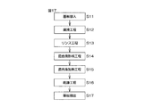
- FIG. 4 is a flowchart for explaining an example of substrate processing by the substrate processing apparatus.
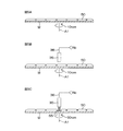
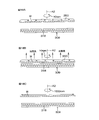
- 5A to 5C are schematic cross-sectional views for explaining the state of the liquid film removal region forming step in the mixed liquid paddle step (S5 in FIG. 4) and the drying step (S6 in FIG. 4).
- FIG. 5D to 5F are schematic cross-sectional views for explaining the state of the liquid film removal region expansion step in the drying step (S6 in FIG. 4).
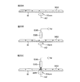
- FIG. 6 is an enlarged cross-sectional view showing the state of the liquid film of the mixed liquid during the liquid film removal region expansion step.
- FIG. 7 is a diagram for explaining a mechanism of Marangoni convection generation in the inner peripheral portion of the liquid film of the mixed solution.
- 8A and 8B are plan views showing the state of the inner peripheral portion of the liquid film of the mixed liquid during the expansion of the liquid film removal region.
- FIG. 9 is a diagram showing a flow distribution model at the gas-liquid-solid interface in the liquid film of water on the upper surface of the substrate according to the reference embodiment.
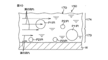
- FIG. 10 is a schematic cross-sectional view showing the movement of fine particles contained in the inner peripheral portion of the liquid film of water according to the reference embodiment.
- FIG. 11 is a schematic plan view showing movement of fine particles contained in the inner peripheral portion of the liquid film of water according to the reference embodiment.
- 12A and 12B are plan views showing the state of the inner peripheral portion of the liquid film of water during expansion of the liquid film removal region according to the reference embodiment.
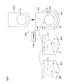
- FIG. 13 is a schematic diagram for explaining a schematic configuration of a substrate processing apparatus according to the second embodiment of the present invention.
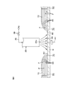
- FIG. 14 is a schematic view showing a state of pulling and drying in the substrate processing apparatus according to the second embodiment of the present invention.
- FIG. 15 is an illustrative sectional view for explaining a configuration example of a processing unit provided in a substrate processing apparatus according to a third embodiment of the present invention.
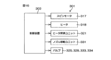
- FIG. 16 is a block diagram for explaining an electrical configuration of a main part of the substrate processing apparatus.
- FIG. 17 is a flowchart for explaining an example of substrate processing by the substrate processing apparatus.
- 18A to 18C are schematic cross-sectional views for explaining the state of the mixed liquid forming step (S14 in FIG. 17), the mixed liquid heating step (S15 in FIG. 17), and the drying step (S16 in FIG. 17). is there.
- 19A to 19C are schematic cross-sectional views showing states of the surface of the substrate in the rinsing step (S13 in FIG.
- FIG. 20 is a schematic cross-sectional view for explaining a configuration example of a processing unit provided in a substrate processing apparatus according to the fourth embodiment of the present invention.
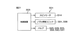
- FIG. 21 is a block diagram for explaining an electrical configuration of a main part of the substrate processing apparatus.
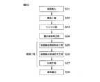
- FIG. 22 is a flowchart for explaining an example of substrate processing by the substrate processing apparatus.
- 23A to 23C are schematic cross-sectional views for explaining the states of the mixed liquid forming step (S24 in FIG. 22) and the liquid film removal region forming step (S25 in FIG. 22).
- FIG. 23D to 23F are schematic cross-sectional views for explaining the state of the liquid film removal region expansion step (S26 in FIG. 22).
- FIG. 24 is an enlarged cross-sectional view for explaining the inner peripheral portion of the liquid film of the water / EG mixed solution.
- FIG. 25 is a schematic diagram for explaining a schematic configuration of a substrate processing apparatus according to the fifth embodiment of the present invention.
- FIG. 26 is a schematic cross-sectional view for explaining the principle of pattern collapse due to surface tension.
- FIG. 1 is an illustrative plan view for explaining an internal layout of a substrate processing apparatus according to a first embodiment of the present invention.
- the substrate processing apparatus 1 is a single wafer processing apparatus that processes substrates W such as silicon wafers one by one.
- the substrate W is a disk-shaped substrate.
- the substrate processing apparatus 1 includes a plurality of processing units 2 that process a substrate W with a processing liquid, a load port LP on which a carrier C that houses a plurality of substrates W processed by the processing unit 2 is placed, a load port It includes transfer robots IR and CR that transfer the substrate W between the LP and the processing unit 2, and a control device 3 that controls the substrate processing apparatus 1.
- the transfer robot IR transfers the substrate W between the carrier C and the transfer robot CR.
- the transfer robot CR transfers the substrate W between the transfer robot IR and the processing unit 2.
- the plurality of processing units 2 have the same configuration, for example.
- FIG. 2 is a schematic cross-sectional view for explaining a configuration example of the processing unit 2.
- the processing unit 2 holds the box-shaped processing chamber 4 and a single substrate W in the processing chamber 4 in a horizontal posture, and rotates the substrate W about a vertical rotation axis A1 passing through the center of the substrate W.
- the processing chamber 4 includes a box-shaped partition wall 10, an FFU (fan filter unit) 11 as a blower unit that sends clean air from above the partition wall 10 into the partition wall 10 (corresponding to the processing chamber 4), and the partition wall 10. And an exhaust device (not shown) for exhausting the gas in the processing chamber 4 from the lower part of the chamber.
- FFU fan filter unit
- the FFU 11 is disposed above the partition wall 10 and attached to the ceiling of the partition wall 10.
- the FFU 11 sends clean air from the ceiling of the partition wall 10 into the processing chamber 4.
- the exhaust device is connected to the bottom of the processing cup 9 via an exhaust duct 13 connected to the inside of the processing cup 9, and sucks the inside of the processing cup 9 from the bottom of the processing cup 9.
- a downflow (downflow) is formed in the processing chamber 4 by the FFU 11 and the exhaust device.
- the spin chuck 5 As the spin chuck 5, a clamping chuck that holds the substrate W horizontally with the substrate W held in the horizontal direction is employed.
- the spin chuck 5 includes a spin motor 14, a spin shaft 15 integrated with a drive shaft of the spin motor 14, and a disc-shaped spin base attached to the upper end of the spin shaft 15 substantially horizontally. 16 and the like.
- the spin base 16 includes a horizontal circular upper surface 16a having an outer diameter larger than the outer diameter of the substrate W.
- a plurality of (three or more, for example, six) clamping members 17 are arranged on the periphery of the upper surface 16a.
- the plurality of sandwiching members 17 are arranged, for example, at equal intervals on the circumference corresponding to the outer peripheral shape of the substrate W at the periphery of the upper surface of the spin base 16.
- the chemical solution supply unit 6 includes a chemical solution nozzle 18.
- the chemical nozzle 18 is, for example, a straight nozzle that discharges liquid in a continuous flow state, and is fixedly disposed above the spin chuck 5 with its discharge port directed toward the center of the upper surface of the substrate W.
- a chemical liquid pipe 19 to which a chemical liquid from a chemical liquid supply source is supplied is connected to the chemical liquid nozzle 18.
- a chemical solution valve 20 for switching supply / stop of supply of the chemical solution from the chemical solution nozzle 18 is interposed in the middle of the chemical solution pipe 19.
- the chemical liquid valve 20 is opened, the continuous flow of chemical liquid supplied from the chemical liquid pipe 19 to the chemical liquid nozzle 18 is discharged from the discharge port set at the lower end of the chemical liquid nozzle 18. Further, when the chemical liquid valve 20 is closed, the supply of the chemical liquid from the chemical liquid pipe 19 to the chemical liquid nozzle 18 is stopped.
- the chemical solution is an etching solution and a cleaning solution. More specifically, the chemical solution includes hydrofluoric acid, SC1 (ammonia hydrogen peroxide aqueous solution mixture), SC2 (hydrochloric hydrogen peroxide aqueous solution mixture), ammonium fluoride, buffered hydrofluoric acid (hydrofluoric acid and ammonium fluoride and Or a mixture thereof.
- hydrofluoric acid includes hydrofluoric acid, SC1 (ammonia hydrogen peroxide aqueous solution mixture), SC2 (hydrochloric hydrogen peroxide aqueous solution mixture), ammonium fluoride, buffered hydrofluoric acid (hydrofluoric acid and ammonium fluoride and Or a mixture thereof.
- the water supply unit 7 includes a first water nozzle 21.
- the first water nozzle 21 is, for example, a straight nozzle that discharges liquid in a continuous flow state, and is fixedly disposed above the spin chuck 5 with its discharge port directed toward the center of the upper surface of the substrate W. Yes.
- a first water pipe 22 to which water from a water supply source is supplied is connected to the first water nozzle 21.
- a first water valve 23 for switching between supply / stop of water from the first water nozzle 21 is interposed in the middle of the first water pipe 22. When the first water valve 23 is opened, the continuous water supplied from the first water pipe 22 to the first water nozzle 21 is discharged from the discharge port set at the lower end of the first water nozzle 21. Is done.
- the water is, for example, deionized water (DIW), but is not limited to DIW, and may be any of carbonated water, electrolytic ionic hydrogen water, ozone water, and hydrochloric acid water having a diluted concentration (for example, about 10 ppm to 100 ppm). Good.
- DIW deionized water
- the chemical nozzle 18 and the first water nozzle 21 do not need to be fixedly arranged with respect to the spin chuck 5.
- the chemical nozzle 18 and the first water nozzle 21 may be arms that can swing in a horizontal plane above the spin chuck 5.
- a so-called scan nozzle configuration may be employed in which the attachment position of the treatment liquid (chemical solution or water) on the upper surface of the substrate W is scanned by the swing of the arm.
- the liquid mixture supply unit 8 moves the liquid mixture nozzle 24 for discharging the water / EG liquid mixture, the first nozzle arm 25 to which the liquid mixture nozzle 24 is attached at the tip, and the first nozzle arm 25. And a first nozzle moving unit 26 that moves the mixed solution nozzle 24.
- the liquid mixture nozzle 24 is, for example, a straight nozzle that discharges a water / EG liquid mixture in a continuous flow state, and is attached to a first nozzle arm 25 that extends in the horizontal direction with its discharge port directed downward, for example. It has been.
- the mixed solution supply unit 8 is connected to the mixing unit 27 for mixing water and EG, and a second water pipe 28 connected to the mixing unit 27 to supply water from the water supply source to the mixing unit 27. And the second water valve 29 and the first flow rate adjusting valve 30 interposed in the second water pipe 28 and the mixing unit 27 to supply EG from the EG supply source to the mixing unit 27.
- the water is, for example, deionized water (DIW), similar to the water supply unit 7, but is not limited to DIW, but is carbonated water, electrolytic ion hydrogen water, ozone water, and hydrochloric acid water having a diluted concentration (for example, about 10 ppm to 100 ppm). Any of these may be sufficient.
- DIW deionized water
- the boiling point and surface tension of water (DIW) are 100 ° C. and 72.75, respectively, at room temperature.
- the boiling point and surface tension of EG are 197.5 ° C. and 47.3, respectively, at room temperature. That is, EG is a liquid having a higher boiling point than water and a lower surface tension than water.
- the second water valve 29 opens and closes the second water pipe 28.
- the first flow rate adjusting valve 30 adjusts the flow rate of water supplied to the mixing unit 27 by adjusting the opening degree of the second water pipe 28.
- the EG valve 32 opens and closes the EG pipe 31.
- the second flow rate adjustment valve 33 adjusts the flow rate of water supplied to the mixing unit 27 by adjusting the opening degree of the EG pipe 31.
- the first and second flow rate adjusting valves 30, 33 include a valve body (not shown) provided with a valve seat therein, a valve body that opens and closes the valve seat, and a valve body between an open position and a closed position. And an actuator (not shown). The same applies to other flow rate adjusting valves.
- the processing cup 9 is disposed outward (in a direction away from the rotation axis A1) from the substrate W held by the spin chuck 5.
- the processing cup 9 surrounds the spin base 16.
- the processing liquid supplied to the substrate W is shaken off around the substrate W.
- the upper end portion 9 a of the processing cup 9 that opens upward is disposed above the spin base 16. Therefore, the processing liquid such as chemical liquid and water discharged around the substrate W is received by the processing cup 9. Then, the processing liquid received by the processing cup 9 is sent to a collection device or a waste liquid device (not shown).
- the processing unit 2 further includes a gas unit 37 for supplying a gas to the upper surface of the substrate W held by the spin chuck 5.
- the gas unit 37 includes a gas nozzle 35 that discharges nitrogen gas as an example of an inert gas toward the upper surface of the substrate W, a second nozzle arm 36 to which the gas nozzle 35 is attached at the tip, and a second nozzle arm 36.
- a second nozzle moving unit 38 that moves the gas nozzle 35 by moving the nozzle arm 36 is included.
- the gas nozzle 35 is attached to a second nozzle arm 36 extending in the horizontal direction with the discharge port directed downward, for example.
- the gas nozzle 35 is connected to a gas pipe 39 to which an inert gas having a high temperature (higher than normal temperature, for example, 30 to 300 ° C.) from an inert gas supply source is supplied.
- a gas valve 40 for switching the supply / stop of supply of the inert gas from the gas nozzle 35 and the opening of the gas pipe 39 are adjusted, and the gas discharged from the gas nozzle 35 is adjusted.
- a third flow rate adjustment valve 41 for adjusting the flow rate of the active gas is interposed.
- the inert gas supplied from the gas pipe 39 to the gas nozzle 35 is discharged from the discharge port. Further, when the gas valve 40 is closed, the supply of the inert gas from the gas pipe 39 to the gas nozzle 35 is stopped.
- the inert gas is not limited to nitrogen gas, but may be CDA (clean air with low humidity).
- FIG. 3 is a block diagram for explaining the electrical configuration of the main part of the substrate processing apparatus 1.
- the control device 3 is configured using, for example, a microcomputer.
- the control device 3 includes an arithmetic unit such as a CPU, a fixed memory device, a storage unit such as a hard disk drive, and an input / output unit.
- the storage unit stores a program executed by the arithmetic unit.
- the control device 3 controls the operations of the spin motor 14, the first and second nozzle moving units 26, 38 and the like according to a predetermined program. Further, the control device 3 includes a chemical liquid valve 20, first and second water valves 23 and 29, an EG valve 32, a gas valve 40, first, second and third flow rate adjusting valves 30, 33, 41 and the like. Controls opening and closing operations.
- FIG. 4 is a flowchart for explaining an example of substrate processing by the substrate processing apparatus 1.
- FIGS. 5A to 5F are schematic diagrams for explaining a mixed liquid paddle process, a liquid film removal region forming step, and a liquid film removal region expanding step. The substrate processing will be described with reference to FIGS. 1 to 5F.
- the unprocessed substrate W is transferred from the carrier C to the processing unit 2 by the transfer robots IR and CR, and is transferred into the processing chamber 4, and the substrate W has its surface (surface to be processed, pattern formation surface in this embodiment).
- the substrate is transferred to the spin chuck 5 while being directed upward, and the substrate W is held on the spin chuck 5 (S1: substrate loading step (substrate holding step)).
- S1 substrate loading step (substrate holding step)
- the mixed solution nozzle 24 and the gas nozzle 35 Prior to the loading of the substrate W, the mixed solution nozzle 24 and the gas nozzle 35 are retracted to the home position set to the side of the spin chuck 5.
- step S2 the control device 3 drives the spin motor 14 to rotate the spin base 16 at a predetermined liquid processing rotation speed (for example, about 800 rpm). Further, the control device 3 opens the chemical liquid valve 20. Thereby, the chemical solution is supplied from the chemical solution nozzle 18 toward the upper surface of the substrate W in the rotating state. The supplied chemical solution spreads over the entire surface of the substrate W by centrifugal force, and the chemical treatment using the chemical solution is performed on the substrate W.
- the control device 3 closes the chemical liquid valve 20 and stops the discharge of the chemical liquid from the chemical liquid nozzle 18.
- the control device 3 executes a water rinsing process (step S3).
- the water rinsing step (S3) is a step of replacing the chemical solution on the substrate W with water and removing the chemical solution from the substrate W.
- the control device 3 opens the first water valve 23. Accordingly, water is supplied from the first water nozzle 21 toward the upper surface of the rotating substrate W. The supplied water is distributed over the entire surface of the substrate W by centrifugal force. The chemical solution adhering to the substrate W is washed away by this water.
- the control device 3 executes a water / EG mixed liquid replacement step (step S4).
- the water / EG mixed solution replacement step (S4) is a step of replacing the water on the substrate W with a water / EG mixed solution.
- the control device 3 controls the first nozzle moving unit 26 to move the mixed solution nozzle 24 from the home position on the side of the spin chuck 5. Move to above the substrate W. Move upward to the center of the upper surface. Then, the control device 3 opens the second water valve 29 and the EG valve 32 and supplies the water / EG mixed liquid to the central portion of the upper surface (front surface) of the substrate W.
- the supplied water / EG mixed solution spreads over the entire surface of the substrate W by centrifugal force and replaces the water on the substrate W (mixed solution replacement step).
- the concentration of EG in the water / EG mixed solution supplied at this time is set to a predetermined concentration in the range of 1 wt% or more and less than 20 wt%, for example.
- the control device 3 controls the spin motor 14 to control the substrate W while the entire upper surface of the substrate W is covered with the water / EG mixed solution. Is gradually reduced from the liquid processing speed to the paddle speed (zero or a low rotational speed of about 40 rpm or less, for example, about 10 rpm). Thereafter, the rotation speed of the substrate W is maintained at the paddle speed. As a result, as shown in FIG.
- a liquid film (hereinafter referred to as a liquid film of a mixed solution) 50 of a water / EG mixed solution covering the entire upper surface of the substrate W is supported in a paddle shape on the upper surface of the substrate W (S5).
- Mixed liquid paddle process liquid film formation process, paddle process
- the centrifugal force acting on the water / EG mixed solution on the substrate W is weakened, and the amount of the water / EG mixed solution discharged from the substrate W is reduced. Since the rinsing step is executed after the chemical step of removing particles from the upper surface of the substrate W with the chemical solution, the liquid film 50 of the mixed solution may contain particles. Further, in the mixed liquid paddle step (S5), the supply of the water / EG mixed liquid to the substrate W may be continued after the liquid film 50 of the paddle-shaped mixed liquid.
- the control device 3 Prior to the end of the mixed liquid paddle process (S5), the control device 3 retreats the mixed liquid nozzle 24 to the home position and controls the second nozzle moving unit 38, as shown in FIG.
- the nozzle 35 is disposed above the substrate W from the home position on the side of the spin chuck 5.
- the control device 3 executes the drying process (step S6).
- the drying step (S6) the liquid film removal region forming step and the liquid film removal region expansion step are executed in this order.
- the liquid film removal region forming step is a step of forming a liquid film removal region 55 from which the liquid mixture has been removed at the center of the liquid film 50 of the liquid mixture.
- the liquid film removal region expansion step is a step of expanding the liquid film removal region 55 to the entire upper surface of the substrate W.
- the control device 3 opens the gas valve 40 to discharge an inert gas from the gas nozzle 35 toward the center of the upper surface of the substrate W (gas blowing step), and the spin motor 14 is turned on.
- the substrate W is controlled to be accelerated to a predetermined drilling speed (for example, about 50 rpm) (high-speed rotation process).
- the inert gas is sprayed on the central portion of the liquid film 50 of the mixed liquid on the upper surface of the substrate W, so that the water / EG mixed liquid in the central portion of the liquid film 50 of the mixed liquid is affected by the spray pressure (gas pressure). It is blown off from the center of the upper surface of the substrate W and removed.
- a relatively strong centrifugal force acts on the liquid film 50 of the mixed liquid on the substrate W.
- a circular liquid film removal region 55 is formed at the center of the upper surface of the substrate W.
- the drilling speed is about 50 rpm, but it may be higher than that.
- the control device 3 controls the spin motor 14 to increase the rotation speed of the substrate W to a predetermined first drying speed (for example, 1000 rpm).
- a predetermined first drying speed for example, 1000 rpm.
- the liquid film removal region 55 expands as shown in FIGS. 5D and 5E. Due to the enlargement of the liquid film removal region 55, the gas-solid interface 60 of the liquid film 50 of the mixed liquid moves between the liquid film removal region 55 and the upper surface of the substrate W outward in the radial direction of the substrate W.
- FIG. 5F the liquid film removal region 55 is expanded over the entire area of the substrate W, whereby the liquid film 50 of the mixed liquid is entirely discharged out of the substrate W.
- the liquid film removal area expansion process is completed.
- the control device 3 closes the gas valve 40 and stops the discharge of the inert gas from the gas nozzle 35.
- control device 3 increases the rotation speed of the substrate W to about 1500 rpm. Thereby, further drying to the upper surface of the board
- substrate W is achieved.
- the control device 3 controls the spin motor 14 to stop the rotation of the spin chuck 5. Thereafter, the transfer robot CR enters the processing unit 2 and carries the processed substrate W out of the processing unit 2 (step S7).
- the substrate W is transferred from the transfer robot CR to the transfer robot IR, and is stored in the carrier C by the transfer robot IR.
- FIG. 6 is an enlarged cross-sectional view showing the state of the liquid film 50 of the mixed liquid during the liquid film removal region expansion step.
- the discharge port 35 a of the gas nozzle 35 is disposed at a lower position facing the upper surface of the substrate W with a predetermined interval.
- the gas valve 40 is opened in this state, the inert gas discharged from the discharge port 35a is blown onto the upper surface of the substrate W.
- the water at the center of the liquid film 50 of the mixed liquid is physically expanded by the spraying pressure (gas pressure), and the water is blown off from the center of the upper surface of the substrate W to be removed.
- a liquid film removal region 55 is formed at the center of the upper surface of the substrate W.
- the inert gas discharged from the discharge port 35a flows radially and horizontally along the upper surface of the substrate W.
- FIG. 7 is a view for explaining a mechanism of generating Marangoni convection 65 inside the inner peripheral portion 70 of the liquid film of the mixed solution.
- the mixed liquid evaporates at the gas-solid liquid interface 60 of the liquid film 50 of the mixed liquid. Further, in the liquid film removal region forming step, the liquid film removal region 55 is enlarged while the liquid mixture is evaporated at the gas-solid interface 60 of the liquid film 50 of the liquid mixture.
- water having a relatively low boiling point mainly evaporates, and as a result, the concentration of EG having a relatively high boiling point and a low surface tension increases.
- a concentration gradient is formed such that the concentration of EG increases as the gas-liquid interface 60 is approached.
- Marangoni convection 65 flowing from the interface vicinity region 71 toward the bulk 72 is generated.
- the Marangoni convection 65 not only cancels out the thermal convection 176 (see FIG. 9) generated in the second portion 70B (see FIG. 9), which will be described later, but also by the Marangoni convection 65, the second portion 70B (see FIG. 9). ), A new flow that flows from the interface vicinity region 71 toward the bulk 72 is created.
- the Marangoni convection 65 continues to be generated after the liquid film removal region 55 is formed until the liquid film removal region 55 covers the entire substrate W.
- the fine particles P2 are included in the inner peripheral portion 70 (specifically, the second portion 70B shown in FIG. 9) of the liquid film of the mixed liquid, as shown in FIG.
- a strong force acts in a direction from the interface vicinity region 71 toward the bulk 72 in response to the Marangoni convection 65, that is, in a direction away from the gas-liquid interface 60.
- the fine particles P2 included in the interface vicinity region 71 move outward in the radial direction (the direction away from the gas-liquid interface 60).
- FIG. 8A and 8B show the state of the inner peripheral portion 70 of the liquid film of the mixed liquid while the liquid film removal region 55 is enlarged.
- the inner peripheral portion 70 of the liquid film of the mixed liquid (specifically, This is a state in which fine particles P2 are included in the second portion 170B) shown in FIG.
- the fine particles P2 are arranged along the gas-liquid interface 60 line.
- the fine particles P2 included in the inner peripheral portion 70 (second portion 70B) of the liquid film of the mixed liquid are subjected to Marangoni convection 65 (see FIG. 6) that flows in a direction away from the gas-liquid interface 60. , Moving outward in the radial direction (in the direction away from the gas-liquid interface 60), and as a result, taken into the bulk 72 of the liquid film 50 of the mixed solution.
- the liquid film removal region 55 expands, the gas-solid interface 60 moves toward the outer side in the radial direction of the substrate W (the direction toward the bulk 72), but the fine particles P2 are taken into the bulk 72. As it is, the liquid film removal region 55 is enlarged.
- region 55 is expanded to the whole region of the board
- substrate W Is dried.
- the fine particles P2 contained in the bulk 72 of the liquid film 50 of the mixed liquid are removed from the upper surface of the substrate W together with the liquid film 50 of the mixed liquid without appearing in the liquid film removal region 55.
- the liquid film 50 of the mixed liquid is formed on the upper surface of the substrate W held in the horizontal posture.
- a liquid film removal region 55 is formed in the liquid film 50 of the mixed liquid, and is further expanded until the liquid film removal region 55 covers the entire area of the substrate W.
- the liquid film removal region 55 expands while the liquid mixture evaporates at the gas-solid liquid interface 60 of the liquid film 50 of the liquid mixture.
- water having a relatively low boiling point mainly evaporates, and as a result, the concentration of EG having a relatively high boiling point increases. Therefore, in the inner peripheral portion 170 of the liquid film of the mixed liquid, a concentration gradient is formed such that the concentration of EG increases as the gas-liquid interface 60 is approached. Due to the difference in EG concentration, Marangoni convection 65 flowing in the direction away from the gas-liquid interface 60 is generated inside the inner peripheral portion 170 of the liquid film of the mixed liquid. The Marangoni convection 65 continues to be generated after the liquid film removal region 55 is formed until the liquid film removal region 55 covers the entire substrate W.
- the fine particles P2 included in the inner peripheral portion 170 of the liquid film of the mixed liquid receive the Marangoni convection 65 and move in a direction away from the gas-liquid interface 60. Therefore, the fine particles P2 are taken into the liquid film 50 of the mixed liquid.
- the liquid film removal region 55 expands, the gas-liquid interface 60 moves toward the outside in the radial direction of the substrate W.
- the fine particles P2 are still taken into the bulk 72 of the liquid film 50 of the mixed liquid, The liquid film removal area 55 is enlarged.
- the fine particles P ⁇ b> 2 are discharged from the upper surface of the substrate W together with the liquid film 50 of the mixed liquid without appearing in the liquid film removal region 55. Thereby, the fine particles P2 do not remain on the upper surface of the substrate W after the substrate W is dried. Therefore, the entire upper surface of the substrate W can be dried while suppressing or preventing the generation of the fine particles P2.
- the concentration of EG having a lower surface tension than water can be increased at the gas-solid liquid interface 60 of the liquid film 50 of the mixed liquid. Therefore, the pattern collapse of the surface of the substrate W during drying can be suppressed.
- the thickness of the liquid film 50 of the mixed liquid formed on the upper surface of the substrate W can be kept thick. Since the thickness of the inner peripheral portion 70 of the liquid film 50 of the mixed liquid is large, the Marangoni convection 65 can be stably generated in the inner peripheral portion 70.
- the concentration gradient of EG in the inner peripheral portion 70 of the liquid film of the mixed liquid can be made abrupt, and therefore, the Marangoni convection 65 generated in the inner peripheral portion 70 of the liquid film of the mixed liquid can be further strengthened. it can.
- the substrate W is rotated at a high speed during the liquid film removal region expansion step, a strong centrifugal force acts on the substrate W, and the centrifugal force causes a difference in film thickness at the inner peripheral portion 170 of the liquid film of the mixed solution. Can be made even more prominent. As a result, the concentration gradient of EG generated in the inner peripheral portion 170 of the liquid film of the mixed liquid can be kept large. Therefore, the Marangoni convection 65 generated in the inner peripheral portion 170 of the liquid film of the mixed liquid is further enhanced. be able to.
- FIG. 9 is a diagram showing a flow distribution model at the gas-liquid-solid interface in the liquid film 150 of water on the upper surface of the substrate W according to the reference embodiment.
- a liquid film 150 of paddle-like water is formed.
- the liquid film removal region forming step and the liquid film removal region expanding step are executed in the same manner as the processing example according to the above-described embodiment.
- thermal convection 176 is generated inside the inner peripheral portion 170 of the liquid film of water in the liquid film removal region expanding step.
- the thermal convection 176 in the inner peripheral portion 170 of the water liquid film flows in a direction away from the gas-liquid interface 60 side, but as shown in FIG.
- the second portion 170B on the gas-solid interface 160 side including the interface vicinity region 171 flows from the bulk 172 side toward the gas-liquid interface 160 side. Therefore, when the fine particle P2 (see FIGS.
- the fine particle P2 is included in the second portion 170B of the inner peripheral portion 170, the fine particle P2 is attracted to the gas-liquid interface 160 side and is near the interface. Aggregates in the region 171. Such aggregation of the fine particles P2 is considered to be caused not only by the above-described thermal convection 176 but also by van der Waals force and Coulomb force between the adjacent fine particles P2.
- FIG. 10 is a schematic cross-sectional view showing the movement of the fine particles P2 included in the inner peripheral portion 170 of the liquid film of water according to the reference embodiment.
- FIG. 11 is a schematic plan view showing the movement of the fine particles P2 included in the inner peripheral portion 170 of the liquid film of water according to the reference embodiment.
- the inner peripheral portion 170 of the liquid film of water is a boundary layer 173 formed near the boundary with the upper surface of the substrate W, and on the opposite side of the upper surface of the substrate W from the boundary layer 173. And a flowing layer 174 to be formed.
- the particles P2 are included in the inner peripheral portion 170 of the water liquid film, the particles P are strongly influenced by the flow in the flow layer 174 regardless of the size of the particle size. Therefore, the particles P in the flow layer 174 can move along the direction along the flow.
- the large particles P1 are affected by the flow, but the fine particles P2 are hardly affected by the flow. That is, the large particle P1 in the boundary layer 173 can move in the boundary layer 173 along the flow direction, but the fine particle P2 in the boundary layer 173 in the direction F along the flow (see FIG. 11). Do not move to. However, the fine particles P2 are not attached to the upper surface of the substrate W, but are provided on the upper surface of the substrate W with a minute interval.
- interference fringes 175 are seen with the naked eye due to the difference in the thickness of the liquid film 50 of water in the interface vicinity region 171.
- the interference fringes 175 are contour lines.
- the fine particles P2 do not move in the direction F (see FIG. 11) along the flow, but can move in the tangential directions D1 and D2 of the interference fringes 175.
- the fine particles P2 are arranged in a line along the tangential directions D1 and D2 of the interference fringes 175 in the interface vicinity region 171. In other words, the fine particles P2 are arranged along the gas-liquid interface 160 line.
- the fine particles P2 form a line for each size of the particles P themselves.
- the fine particles P21 having a relatively large diameter are disposed radially outward than the fine particles P22 having a relatively small diameter.
- 12A and 12B are plan views showing the state of the inner peripheral portion 170 of the liquid film of water during expansion of the liquid film removal region 55 according to the reference embodiment.
- FIG. 12A shows a state in which fine particles P2 are included in the inner peripheral portion 170 (specifically, the second portion 170B shown in FIG. 10) of the liquid film of water.
- the fine particles P2 are arranged along the gas-liquid interface 160 line.
- the fine particles P ⁇ b> 2 included in the interface vicinity region 71 move from the gas-liquid interface 60 to the liquid film removal region 55 and are deposited on the liquid film removal region 55. Then, fine particles P2 remain on the upper surface of the substrate W after the liquid film 150 of water is removed.
- the present invention can also be applied to a batch type substrate processing apparatus.
- FIG. 13 is a schematic diagram for explaining a schematic configuration of a substrate processing apparatus 201 according to the second embodiment of the present invention.
- FIG. 14 is a schematic diagram showing a state of pulling and drying in the substrate processing apparatus 201.
- the substrate processing apparatus 201 is a batch type substrate processing apparatus that collectively processes a plurality of substrates W.
- the substrate processing apparatus 201 includes a chemical solution storage tank 202 for storing a chemical solution, a water storage tank 203 for storing water, a water / EG mixed solution storage tank 204 for storing a water / EG mixed solution, and a water / EG mixed solution storage.
- a lifter 205 for immersing the substrate W in the water / EG mixed solution stored in the tank 204 and a lifter lifting / lowering unit 206 for lifting / lowering the lifter 205 are included.
- the EG concentration of the water / EG mixed solution stored in the water / EG mixed solution storage tank 204 is set to a predetermined concentration in the range of, for example, 1 wt% or more and less than 20 wt%.
- the lifter 205 supports each of the plurality of substrates W in a vertical posture.
- the lifter lifting / lowering unit 206 includes a processing position where the substrate W held by the lifter 205 is located in the water / EG mixed solution storage tank 204 (a position indicated by a solid line in FIG. 13), and a substrate W held by the lifter 205. Is located above the water / EG mixed liquid storage tank 204 (position indicated by a two-dot chain line in FIG. 13). The lifter 205 is moved up and down.
- the plurality of substrates W carried into the processing unit of the substrate processing apparatus 201 are immersed in the chemical solution stored in the chemical solution storage tank 202. Thereby, chemical processing (cleaning processing or etching processing) is performed on each substrate W.
- chemical processing cleaning processing or etching processing
- the plurality of substrates W are pulled up from the chemical solution storage tank 202 and transferred to the water storage tank 203.
- the plurality of substrates W are immersed in the water stored in the water storage tank 203.
- the rinsing process is performed on the substrate W.
- the substrate W is pulled up from the water storage tank 203 and transferred to the water / EG mixed liquid storage tank 204.
- the plurality of substrates W held by the lifter 205 are immersed in the water / EG mixed solution.
- the water / EG mixed solution is supplied to the surface (surface to be processed, in this embodiment, the pattern forming surface) Wa of the substrate W, and the water adhering to the surface Wa of the substrate W is replaced with the water / EG mixed solution. (Mixed liquid replacement step).
- the lifter lifting / lowering unit 206 is controlled to move the lifter 205 from the processing position to the retracted position. As a result, the plurality of substrates W immersed in the water / EG mixed solution are pulled up from the water / EG mixed solution.
- pulling drying (mixed solution removing step) is performed. As shown in FIG. 14, the pulling drying is performed while blowing an inert gas (for example, nitrogen gas) onto the surface Wa of the substrate W pulled up from the water / EG mixed solution storage tank 204 and at a relatively slow speed (for example, several mm). / Second) by pulling up the substrate W.
- an inert gas for example, nitrogen gas
- the liquid removal region 255 is expanded over the entire area of the substrate W. After the formation of the liquid removal region 255, an EG concentration gradient is formed in the vicinity of the interface 270 of the water / EG mixed solution due to the evaporation of water at the gas-solid liquid interface 260. Marangoni convection flowing downward from the liquid interface 260 is generated.
- the fine particles contained in the water / EG mixed solution are subjected to Marangoni convection and move in a direction away from the gas-solid interface 260 (ie, downward). Therefore, the fine particles are taken into the water / EG mixed solution stored in the water / EG mixed solution storage tank 204. Then, all the substrates W are pulled up from the water / EG mixed solution without causing the fine particles to appear in the liquid removal region 255, and the entire surface Wa of the substrate W is dried. Therefore, the entire upper surface of the substrate W can be dried while suppressing or preventing the generation of fine particles.
- the concentration of EG can be kept high at the gas-liquid interface 60 during the pull-up drying. Since the surface tension of EG is lower than that of water, pattern collapse of the surface of the substrate W after drying can be suppressed.
- FIG. 15 is an illustrative sectional view for explaining a configuration example of the processing unit 302 provided in the substrate processing apparatus 301 according to the third embodiment of the present invention.
- the processing unit 302 holds the substrate-shaped processing chamber 304 and a single substrate W in the processing chamber 304 in a horizontal posture, and rotates the substrate W about a vertical rotation axis A2 passing through the center of the substrate W.
- a spin chuck (substrate holding unit) 305, a chemical solution supply unit 306 for supplying a chemical solution to the upper surface of the substrate W held by the spin chuck 305, and an upper surface of the substrate W held by the spin chuck 305 are processed.
- the water supply unit (treatment liquid supply unit) 307 for supplying water and the upper surface (surface) of the substrate W have a boiling point higher than that of water (treatment liquid) and the water (treatment liquid).
- An EG supply unit for supplying ethylene glycol (hereinafter referred to as “EG”) as an example of a low surface tension liquid having a low surface tension.
- EG ethylene glycol
- a liquid film of a water / EG mixed solution (hereinafter referred to as a “liquid film of the mixed solution”) formed on the upper surface of the substrate W so as to face the lower surface of the substrate W held by the spin chuck 305.
- 350 includes a hot plate (heating unit) 309 for heating from below through the substrate W, and a cylindrical processing cup 310 surrounding the spin chuck 305.
- the processing chamber 304 includes a box-shaped partition 311, an FFU (fan filter unit) 312 as a blower unit that sends clean air from above the partition 311 into the partition 311 (corresponding to the processing chamber 304), and the partition 311. And an exhaust device (not shown) for exhausting the gas in the processing chamber 304 from the lower part of the chamber.
- FFU fan filter unit
- the processing chamber 304 includes a box-shaped partition 311, an FFU (fan filter unit) 312 as a blower unit that sends clean air from above the partition 311 into the partition 311 (corresponding to the processing chamber 304), and the partition 311.
- an exhaust device (not shown) for exhausting the gas in the processing chamber 304 from the lower part of the chamber.
- the FFU 312 is disposed above the partition wall 311 and is attached to the ceiling of the partition wall 311.
- the FFU 312 sends clean air from the ceiling of the partition 311 into the processing chamber 304.
- the exhaust device is connected to the bottom of the processing cup 310 via an exhaust duct 313 connected to the processing cup 310, and sucks the inside of the processing cup 310 from the bottom of the processing cup 310.
- a downflow (downflow) is formed in the processing chamber 304 by the FFU 312 and the exhaust device.
- the spin chuck 305 a clamping chuck that holds the substrate W horizontally with the substrate W held in the horizontal direction is employed.
- the spin chuck 305 is arranged on the spin base 315 at equal intervals, a cylindrical spin shaft 314 extending vertically, a disc-shaped spin base 315 attached to the upper end of the spin shaft 314 in a horizontal posture, and the spin base 315.
- a plurality of (at least three, for example, six) holding pins 316 and a spin motor 317 connected to the spin shaft 314 are included.
- the plurality of sandwiching pins 316 are arranged, for example, at equal intervals on the circumference corresponding to the outer peripheral shape of the substrate W at the peripheral edge of the upper surface of the spin base 315.
- Each of the plurality of sandwiching pins 316 is an upward sandwiching pin (a sandwiching pin whose lower side is supported). The sandwiching position where the substrate W can be sandwiched by contacting the peripheral edge of the substrate W, and the sandwiching position. Is also displaced between the opening position of the substrate W radially outward.
- the spin chuck 305 holds each of the holding pins 316 in contact with the peripheral edge of the substrate W, whereby the substrate W is firmly held by the spin chuck 305.
- Each clamping pin 316 is coupled to a driving mechanism (not shown) for displacing the clamping pin 316.
- a downward pin pin (a pin pin whose upper side is supported) may be employed as the pinch member.
- the spin motor 317 is, for example, an electric motor.
- the substrate W held by the pin 316 is rotated integrally with the spin base 315 around a vertical rotation axis A2 passing through the center of the substrate W when the rotational driving force from the spin motor 317 is transmitted to the spin shaft 314. Be made.
- the hot plate 309 is formed, for example, in a disk shape having a horizontal flat surface, and has an outer diameter equivalent to the outer diameter of the substrate W.
- the hot plate 309 has a circular upper surface facing the lower surface (back surface) of the substrate W held by the spin chuck 305.
- the hot plate 309 is disposed in a horizontal posture between the upper surface of the spin base 315 and the lower surface of the substrate W held by the spin chuck 305.
- the hot plate 309 is formed using ceramic or silicon carbide (SiC), and a heater 318 is embedded therein. The entire hot plate 309 is heated by the heating of the heater 318, and the hot plate 309 functions to heat the substrate W.
- the heat generation amount per unit area of the upper surface when the heater 318 is on is set to be uniform.
- the hot plate 309 is supported by a support rod 320 that is inserted in a vertical direction (thickness direction of the spin base 315) along a rotation axis A2 through a through hole 319 that passes through the spin base 315 and the spin shaft 314 in the vertical direction.
- the lower end of the support rod 320 is fixed to a peripheral member below the spin chuck 305. Since the hot plate 309 is not connected to the spin motor 317, even when the substrate W is rotating, the hot plate 309 does not rotate but is stationary (non-rotating state).
- a heater lifting / lowering unit 321 for lifting / lowering the hot plate 309 is coupled to the support rod 320.
- the hot plate 309 is lifted and lowered by the heater lifting / lowering unit 321 while maintaining the horizontal posture.
- the heater lifting / lowering unit 321 is configured by, for example, a ball screw or a motor.
- the hot plate 309 is minutely moved to a lower position (see FIG. 18A and the like) separated from the lower surface of the substrate W held by the spin chuck 305 and a lower surface of the substrate W held by the spin chuck 305 by driving the heater lifting / lowering unit 321. It is moved up and down between the upper positions (see FIG. 18B) approaching at intervals.
- the distance between the lower surface of the substrate W and the upper surface of the hot plate 309 is set to about 0.3 mm, for example, and the upper surface of the hot plate 309 is in the lower position.
- the distance between the lower surface of the substrate W and the upper surface of the hot plate 309 is set to about 10 mm, for example.
- the distance between the hot plate 309 and the substrate W can be changed.
- the chemical solution supply unit 306 includes a chemical solution nozzle 323.
- the chemical liquid nozzle 323 is, for example, a straight nozzle that discharges liquid in a continuous flow state, and is fixedly disposed above the spin chuck 305 with its discharge port directed toward the center of the upper surface of the substrate W.
- a chemical solution pipe 324 to which a chemical solution from a chemical solution supply source is supplied is connected to the chemical solution nozzle 323.
- a chemical solution valve 325 for switching supply / stop of supply of the chemical solution from the chemical solution nozzle 323 is interposed in the middle of the chemical solution pipe 324.
- the chemical liquid valve 325 When the chemical liquid valve 325 is opened, the continuous flow of chemical liquid supplied from the chemical liquid pipe 324 to the chemical liquid nozzle 323 is discharged from the discharge port set at the lower end of the chemical liquid nozzle 323. Further, when the chemical liquid valve 325 is closed, the supply of the chemical liquid from the chemical liquid pipe 324 to the chemical liquid nozzle 323 is stopped.
- the chemical solution is an etching solution and a cleaning solution. More specifically, the chemical solution includes hydrofluoric acid, SC1 (ammonia hydrogen peroxide aqueous solution mixture), SC2 (hydrochloric hydrogen peroxide aqueous solution mixture), ammonium fluoride, buffered hydrofluoric acid (hydrofluoric acid and ammonium fluoride and Or a mixture thereof.
- hydrofluoric acid includes hydrofluoric acid, SC1 (ammonia hydrogen peroxide aqueous solution mixture), SC2 (hydrochloric hydrogen peroxide aqueous solution mixture), ammonium fluoride, buffered hydrofluoric acid (hydrofluoric acid and ammonium fluoride and Or a mixture thereof.
- the water supply unit 307 includes a water nozzle 326.
- the water nozzle 326 is, for example, a straight nozzle that discharges liquid in a continuous flow state, and is fixedly disposed above the spin chuck 305 with its discharge port directed toward the center of the upper surface of the substrate W.
- a water pipe 327 to which water from a water supply source is supplied is connected to the water nozzle 326.
- a water valve 328 for switching supply / stop of water from the water nozzle 326 is interposed in the middle of the water pipe 327. When the water valve 328 is opened, the continuous water supplied from the water pipe 327 to the water nozzle 326 is discharged from the discharge port set at the lower end of the water nozzle 326.
- the water is, for example, deionized water (DIW), but is not limited to DIW, and may be any of carbonated water, electrolytic ionic hydrogen water, ozone water, and hydrochloric acid water having a diluted concentration (for example, about 10 ppm to 100 ppm). Good.
- DIW deionized water
- the boiling point and surface tension of water (DIW) are 100 ° C. and 72.75, respectively, at room temperature.
- the chemical nozzle 323 and the water nozzle 326 do not need to be fixedly arranged with respect to the spin chuck 305, and are attached to an arm that can swing in a horizontal plane above the spin chuck 305, for example.
- a so-called scan nozzle configuration may be employed in which the position of the treatment liquid (chemical liquid or water) on the upper surface of the substrate W is scanned by the swing of the arm.
- the EG supply unit 308 includes an EG nozzle 329 for discharging EG, a first nozzle arm 330 having the EG nozzle 329 attached to the tip, and the first nozzle arm 330 by moving the EG nozzle 329.
- a first nozzle moving unit 331 that moves the first nozzle moving unit 331.
- the EG nozzle 329 is, for example, a straight nozzle that discharges EG in a continuous flow state, and is attached to a first nozzle arm 330 that extends in the horizontal direction with its discharge port directed downward, for example.
- the EG supply unit 308 is connected to the EG nozzle 329, and an EG pipe 332 that supplies EG from the EG supply source to the EG nozzle 329, and an EG valve for switching supply / stop of supply of EG from the EG nozzle 329.
- 333 and a first flow rate adjustment valve 334 for adjusting the flow rate of EG discharged from the EG nozzle 329 by adjusting the opening degree of the EG pipe 332.
- the first flow rate adjusting valve 334 includes a valve body (not shown) having a valve seat therein, a valve body that opens and closes the valve seat, and an actuator that moves the valve body between an open position and a closed position ( (Not shown). The same applies to other flow rate adjusting valves.
- the boiling point and surface tension of EG are 197.5 degreeC and 47.3, respectively, at normal temperature. That is, EG is a liquid having a higher boiling point than water and a lower surface tension than water.
- the processing cup 310 is disposed outward (in a direction away from the rotation axis A2) from the substrate W held by the spin chuck 305.
- the processing cup 310 surrounds the spin base 315.
- the processing liquid supplied to the substrate W is shaken off around the substrate W.
- the upper end portion 310 a of the processing cup 310 that opens upward is disposed above the spin base 315. Therefore, the processing liquid such as chemical liquid and water discharged around the substrate W is received by the processing cup 310. Then, the processing liquid received by the processing cup 310 is sent to a recovery device or a waste liquid device (not shown).
- FIG. 16 is a block diagram for explaining an electrical configuration of a main part of the substrate processing apparatus 301.
- the control device 303 controls operations of the spin motor 317, the heater lifting / lowering unit 321, the first nozzle moving unit 331, and the like according to a predetermined program.
- the control device 303 also controls the opening / closing operations of the chemical liquid valve 325, the water valve 328, the EG valve 333, the first flow rate adjustment valve 334, and the like. Further, the control device 303 controls on / off of the heater 318.
- FIG. 17 is a flowchart for explaining an example of substrate processing by the substrate processing apparatus 301.
- 18A to 18C are schematic cross-sectional views for explaining the state of the mixed liquid forming step (S14 in FIG. 17), the mixed liquid heating step (S15 in FIG. 17), and the drying step (S16 in FIG. 17).
- 19A to 19F show the substrate W in the rinsing step (S13 in FIG. 17), the mixed solution forming step (S14 in FIG. 17), the mixed solution heating step (S15 in FIG. 17), and the drying step (S16 in FIG. 17). It is an illustrative sectional view showing the state of the surface. The substrate processing will be described with reference to FIGS. 15 to 19F.
- the unprocessed substrate W is transferred from the carrier C to the processing unit 302 by the transfer robots IR and CR, and is transferred into the processing chamber 304, where the substrate W has its surface (surface to be processed, pattern formation surface in this embodiment).
- the substrate is transferred to the spin chuck 305 while being directed upward, and the substrate W is held on the spin chuck 305 (S11: substrate loading step (substrate holding step)).
- the EG nozzle 329 Prior to the loading of the substrate W, the EG nozzle 329 is retracted to the home position set on the side of the spin chuck 305.
- the hot plate 309 is disposed at a lower position away from the lower surface of the substrate W. At this time, the heater 318 is in an off state.
- the control device 303 controls the spin motor 317 to start rotating the substrate W and accelerate it to a predetermined liquid processing rotation speed (for example, about 800 rpm).
- control device 303 turns on the heater 318.
- the heater 318 generates heat, and the upper surface temperature of the hot plate 309 is raised to a predetermined high temperature.
- the surface of the hot plate 309 becomes a high temperature state by turning on the heater 318, the substrate W is hardly heated by the heat from the hot plate 309 because the hot plate 309 is disposed at the lower position.
- the control device 303 executes a chemical liquid process (step S12). Specifically, after the rotation speed of the substrate W reaches the liquid processing speed, the control device 303 opens the chemical liquid valve 325. Thereby, the chemical solution is supplied from the chemical solution nozzle 323 toward the upper surface of the rotating substrate W. The supplied chemical solution spreads over the entire surface of the substrate W by centrifugal force, and the chemical treatment using the chemical solution is performed on the substrate W. When a predetermined period has elapsed from the start of the discharge of the chemical liquid, the control device 303 closes the chemical liquid valve 325 and stops the discharge of the chemical liquid from the chemical liquid nozzle 323.
- the rinsing step (S13) is a step of removing the chemical solution from the substrate W by replacing the chemical solution on the substrate W with water.
- the control device 303 opens the water valve 328. Thereby, water is supplied from the water nozzle 326 toward the upper surface of the rotating substrate W. The supplied water is distributed over the entire surface of the substrate W by centrifugal force. The chemical solution adhering to the substrate W is washed away by this water.
- the control device 303 controls the spin motor 317 so that the rotation speed of the substrate W is changed from the liquid processing speed while the entire upper surface of the substrate W is covered with water. Decrease in steps to a paddle speed (zero or a low rotational speed of about 40 rpm or less, for example, about 10 rpm). Thereafter, the rotation speed of the substrate W is maintained at the paddle speed. Thereby, a liquid film of water covering the entire upper surface of the substrate W is supported on the upper surface of the substrate W in a paddle shape.
- the centrifugal force acting on the water film on the upper surface of the substrate W is smaller than the surface tension acting between the water and the upper surface of the substrate W, or the centrifugal force and the surface tension are It is almost antagonistic. Due to the deceleration of the substrate W, the centrifugal force acting on the water on the substrate W is weakened, and the amount of water discharged from the substrate W is reduced. As a result, as shown in FIG. 19A, a paddle-like water liquid film 345 is formed on the upper surface of the substrate W. Thereafter, the rotation speed of the substrate W is maintained at the paddle speed. Although the supply of water to the substrate W is stopped after the formation of the water liquid film 345, the supply of water to the substrate W may be continued after the formation of the paddle-shaped water liquid film.
- step S14 in FIG. 17 a mixed liquid forming step
- the control device 303 controls the first nozzle moving unit 331 to move the EG nozzle 329 from the home position to a processing position above the substrate W. Let Thereafter, the control device 303 opens the EG valve 333 and discharges EG from the EG nozzle 329 toward the upper surface of the substrate W. Further, the control device 303 moves the supply position of the EG with respect to the upper surface of the substrate W between the central portion and the peripheral portion. Thereby, the water supply position scans the entire upper surface of the substrate W, and EG is directly applied to the entire upper surface of the substrate W.
- control device 303 executes a mixed liquid heating step (step S15 in FIG. 17).
- the control device 303 controls the heater lifting / lowering unit 321 to raise the hot plate 309 from the lower position (see FIG. 18A and the like) to the upper position as shown in FIG. 18B.
- the substrate W is heated by heat radiation from the upper surface of the hot plate 309 in the upper position.
- the liquid film 350 of the mixed liquid on the upper surface of the substrate W is also raised to a high temperature that is about the same as the temperature of the substrate W.
- the heating temperature of the mixed liquid to the liquid film 350 is set to a predetermined high temperature (for example, about 150 ° C.) that is higher than the boiling point of water and lower than the boiling point of EG.
- the water contained in the liquid film 350 of the mixed liquid boils and the water evaporates from the liquid film 350 of the mixed liquid by heating the liquid film 350 of the mixed liquid.
- the liquid film contains only EG. That is, an EG liquid film 351 is formed on the upper surface of the substrate W. Thereby, the water on the upper surface of the substrate W can be completely replaced with EG.
- the control device 303 controls the heater elevating unit 321 to move the hot plate 309 to the upper position (FIG. 18B) as shown in FIG. 18C. Refer to the lower position. Thereby, the heating of the substrate W by the hot plate 309 is completed.
- the control device 303 controls the spin motor 317 to accelerate the rotation speed of the substrate W to a drying speed (for example, 1500 rpm) as shown in FIG. 18C.
- a drying speed for example, 1500 rpm
- the EG liquid film 351 on the upper surface of the substrate W is shaken off, and the substrate W is dried (spin dry; S16 in FIG. 17: drying step).
- EG is removed from between the structures ST of the pattern PA. Since EG has a lower surface tension than water, pattern collapse in the drying step (S16) can be suppressed.
- the control device 303 controls the spin motor 514 to stop the rotation of the spin chuck 305. In addition, the control device 303 turns off the heater 318. Thereafter, the transfer robot CR enters the processing unit 302 and carries the processed substrate W out of the processing unit 302 (step S17 in FIG. 17). The substrate W is transferred from the transfer robot CR to the transfer robot IR, and is stored in the carrier C by the transfer robot IR.
- EG is supplied to the liquid film 345 of the water on the substrate W.
- water and EG are mixed, and a liquid film 350 of the mixed liquid is formed on the upper surface of the substrate W.
- the liquid film 350 of the mixed liquid is heated to evaporate water contained in the liquid film 350 of the mixed liquid, and as a result, the water in the liquid film 350 of the mixed liquid can be completely replaced with EG.
- the replacement rate of the water with the EG can be increased.
- the water on the upper surface of the substrate W can be completely replaced with EG in a short time. Therefore, the upper surface of the substrate W can be dried in a short time while suppressing the collapse of the pattern PA. Thereby, the drying time of the substrate W can be shortened, and the amount of EG used can be reduced.
- the heating temperature of the mixed liquid to the liquid film 350 is set to a predetermined high temperature (for example, about 150 ° C.) that is higher than the boiling point of water and lower than the boiling point of EG. ing. Therefore, EG in the water / EG mixture hardly evaporates, but the evaporation of water in the water / EG mixture is promoted. That is, only water in the liquid film 350 of the mixed liquid can be efficiently evaporated. Thereby, complete replacement with the low surface tension liquid can be realized in a shorter time.
- a predetermined high temperature for example, about 150 ° C.
- the heating temperature of the mixed liquid to the liquid film 350 is lower than the boiling point of the EG, the liquid film of EG having a predetermined thickness is held on the upper surface of the substrate W after the mixed liquid heating step (S15 in FIG. 17). it can.
- a liquid film 350 of a mixed liquid is formed on the upper surface of the substrate W by forming a paddle-like liquid film 345 on the upper surface of the substrate W and supplying EG to the liquid film 345 of the water. Emission of EG from W can be suppressed. Thereby, the further usage-amount reduction of EG can be aimed at.
- FIG. 20 is an illustrative sectional view for explaining a configuration example of the processing unit 502 provided in the substrate processing apparatus 501 according to the fourth embodiment of the present invention.
- the main difference between the processing unit 502 and the processing unit 302 according to the third embodiment is that a spin chuck (substrate holding unit) 505 is provided instead of the spin chuck 305. That is, the processing unit 302 does not include the hot plate 309.
- a gas unit 537 for supplying gas to the upper surface of the substrate W held by the spin chuck 505 is further provided. It is a point to include.
- the spin chuck 505 As the spin chuck 505, a sandwich chuck that holds the substrate W horizontally with the substrate W sandwiched in the horizontal direction is employed.
- the spin chuck 505 includes a spin motor 514, a spin shaft 515 integrated with a drive shaft of the spin motor 514, and a disk-shaped spin base attached substantially horizontally to the upper end of the spin shaft 515. 516.
- the spin base 516 includes a horizontal circular upper surface 516a having an outer diameter larger than the outer diameter of the substrate W.
- a plurality of (three or more, for example, six) clamping members 517 are arranged on the peripheral edge of the upper surface 516a.
- the plurality of sandwiching members 517 are arranged, for example, at equal intervals on the circumference corresponding to the outer peripheral shape of the substrate W at the peripheral edge of the upper surface of the spin base 516.
- the gas unit 537 includes a gas nozzle 535 that discharges nitrogen gas as an example of an inert gas toward the upper surface of the substrate W, a second nozzle arm 536 having the gas nozzle 535 attached to the tip, and a second nozzle arm 536. And a second nozzle moving unit 538 that moves the gas nozzle 535 by moving the nozzle arm 536.
- the gas nozzle 535 is attached to a second nozzle arm 536 that extends in the horizontal direction with its discharge port directed downward, for example.
- the gas nozzle 535 is connected to a gas pipe 539 to which an inert gas having a high temperature (higher than normal temperature, for example, 30 to 300 ° C.) from an inert gas supply source is supplied.
- a gas valve 540 for switching between supply / stop of supply of the inert gas from the gas nozzle 535 and an opening degree of the gas pipe 539 are adjusted in the middle of the gas pipe 539 and discharged from the gas nozzle 535.
- a second flow rate adjustment valve 541 for adjusting the flow rate of the active gas is interposed.
- the inert gas supplied from the gas pipe 539 to the gas nozzle 535 is discharged from the discharge port. Further, when the gas valve 540 is closed, the supply of the inert gas from the gas pipe 539 to the gas nozzle 535 is stopped.
- the inert gas is not limited to nitrogen gas, but may be CDA (clean air with low humidity).
- FIG. 21 is a block diagram for explaining an electrical configuration of a main part of the substrate processing apparatus 501.
- the control device 303 controls operations of the spin motor 514, the first and second nozzle moving units 331, 538, and the like according to a predetermined program. Further, the control device 303 controls the opening / closing operations of the chemical liquid valve 325, the water valve 328, the EG valve 333, the gas valve 540, the first and second flow rate adjusting valves 334, 541, and the like.
- FIG. 22 is a flowchart for explaining an example of substrate processing by the substrate processing apparatus 501.
- FIGS. 23A to 23F are diagrams for explaining the states of the mixed liquid formation step (S24 in FIG. 22), the liquid film removal region formation step (S25 in FIG. 22), and the liquid film removal region expansion step (S26 in FIG. 22).
- FIG. The substrate processing by the substrate processing apparatus 501 will be described with reference to FIGS. 21 to 23F.
- the unprocessed substrate W is carried into the processing chamber 504 by the transfer robots IR and CR, and the spin chuck 505 with the surface of the substrate W (processing target surface, in this embodiment, the pattern formation surface) facing upward. And the substrate W is held on the spin chuck 505 (S21: substrate loading step (substrate holding step)).
- substrate loading step substrate holding step
- the EG nozzle 329 and the gas nozzle 535 are retracted to the home position set to the side of the spin chuck 505.
- the control device 303 After the transfer robot CR is retracted outside the processing unit 502, the control device 303 starts the rotation of the substrate W, and sequentially performs the chemical solution process (step S22), the rinse process (step S23), and the mixed liquid formation process (step S24). Execute.
- the chemical liquid process (S22), the rinsing process (S23), and the mixed liquid forming process (S24) are respectively the chemical liquid process (S12), the rinsing process (S13), and the mixed liquid forming process (S14) according to the third embodiment. Since they are equivalent steps, their explanation is omitted.
- a liquid film 350 of the mixed liquid is formed on the upper surface of the substrate W (see FIGS. 23A and 19C).
- the control device 303 controls the second nozzle moving unit 538 to move the gas nozzle 535 to the home position on the side of the spin chuck 505 as shown in FIG. 23B. To the upper side of the substrate W.
- the control device 303 executes a drying step.
- the liquid film removal region forming step (S25), the liquid film removal region expansion step (S26), and the acceleration step (S27) are executed in this order.
- the liquid film removal region forming step (S25) is a step of forming a liquid film removal region 355 from which the liquid mixture has been removed at the center of the liquid film 350 of the liquid mixture.
- the liquid film removal region expansion step (S26) is a step of expanding the liquid film removal region 355 to the entire upper surface of the substrate W.
- the control device 303 opens the gas valve 540, discharges an inert gas from the gas nozzle 535 toward the center of the upper surface of the substrate W (gas blowing step), and spins.
- the motor 514 is controlled to accelerate the substrate W to a predetermined drilling speed (for example, about 50 rpm) (high-speed rotation process).
- the inert gas is sprayed on the central part of the liquid film 350 of the mixed liquid on the upper surface of the substrate W, so that the water / EG mixed liquid in the central part of the liquid film 350 of the mixed liquid is affected by the spraying pressure (gas pressure). It is blown off from the center of the upper surface of the substrate W and removed.
- a relatively strong centrifugal force acts on the liquid film 350 of the mixed liquid on the substrate W.
- a circular liquid film removal region 355 is formed at the center of the upper surface of the substrate W, as shown in FIG. 23C.
- the drilling speed is about 50 rpm, but it may be higher than that.
- the control device 303 controls the spin motor 514 to increase the rotation speed of the substrate W to a predetermined first drying speed (for example, 1000 rpm).
- a predetermined first drying speed for example, 1000 rpm.
- the liquid film removal region 355 expands as shown in FIGS. 23D and 23E. Due to the enlargement of the liquid film removal region 355, the gas-solid interface 360 of the liquid film 350 of the mixed liquid moves between the liquid film removal region 355 and the upper surface of the substrate W outward in the radial direction of the substrate W.
- FIG. 23F the liquid film removal region 355 is expanded over the entire area of the substrate W, whereby the liquid film 350 of the mixed liquid is entirely discharged out of the substrate W.
- the liquid film removal region expansion process is completed.
- the control device 303 closes the gas valve 540 and stops the discharge of the inert gas from the gas nozzle 535.
- control device 303 executes an acceleration process (S27). Specifically, the control device 303 increases the rotation speed of the substrate W to about 1500 rpm. Thereby, further drying to the upper surface of the board
- the control device 303 controls the spin motor 514 to stop the rotation of the spin chuck 305. Thereafter, the transfer robot CR enters the processing unit 502 and carries the processed substrate W out of the processing unit 502 (step S28).
- the substrate W is transferred from the transfer robot CR to the transfer robot IR, and is stored in the carrier C by the transfer robot IR.
- FIG. 23 is an enlarged cross-sectional view for explaining the inner peripheral portion of the liquid film 350 of the mixed liquid.
- the concentration of EG increases.
- the EG concentration of the liquid film 350 of the mixed liquid is determined so that only EG exists at the gas-liquid interface 360 (that is, the supply amount of EG in the mixed liquid forming step (S24) is determined). Is). In this case, water can be completely replaced with EG at the gas-solid liquid interface 360.
- EG is supplied to the liquid film 345 of the water on the substrate W.
- water and EG are mixed, and a liquid film 350 of the mixed liquid is formed on the upper surface of the substrate W.
- a liquid film removal region 355 is formed in the liquid film 350 of the mixed liquid, and further, the liquid film removal region 355 is expanded until the entire region of the substrate W is covered.
- the liquid film removal region 355 expands while the water / EG mixed liquid evaporates at the gas-solid liquid interface 360 of the liquid film 350 of the mixed liquid.
- the concentration of EG increases.
- only EG is present at the gas-solid liquid interface 360, and a concentration gradient is formed in the inner peripheral portion 370 of the liquid film of the mixed liquid such that the concentration of EG decreases as the distance from the gas-solid liquid interface 360 increases.
- water can be completely replaced with EG at the gas-solid liquid interface 360.
- the surface tension of the liquid acts on the pattern PA.
- the liquid film 350 of the mixed liquid is formed by supplying the EG, and the water contained in the liquid film 350 of the mixed liquid is evaporated to leave only the EG, so that the replacement rate of the water with the EG can be increased. it can.
- the water on the upper surface of the substrate W can be completely replaced with EG in a short time. Therefore, the upper surface of the substrate W can be dried in a short time while suppressing the collapse of the pattern PA. Thereby, the drying time of the substrate W can be shortened, and the amount of EG used can be reduced.
- the substrate W by supplying a high-temperature inert gas to the upper surface of the substrate W, evaporation of water at the gas-solid liquid interface 360 of the liquid film 350 of the mixed liquid can be promoted. Thereby, the EG can be completely replaced at the gas-solid liquid interface 360 of the liquid film 350 of the mixed liquid.
- a liquid film 350 of a mixed liquid is formed on the upper surface of the substrate W by forming a paddle-like liquid film 345 on the upper surface of the substrate W and supplying EG to the liquid film 345 of the water. Emission of EG from W can be suppressed. Thereby, the further usage-amount reduction of EG can be aimed at.
- FIG. 25 is a schematic diagram for explaining a schematic configuration of a substrate processing apparatus 601 according to the fifth embodiment of the present invention.
- the substrate processing apparatus 601 is a batch type substrate processing apparatus that collectively processes a plurality of substrates W.
- the substrate processing apparatus 601 includes a chemical solution storage tank 602 for storing a chemical solution, a water storage tank 603 for storing water, an EG storage tank 604 for storing an EG mixed solution, and an EG stored in the EG storage tank 604.
- a lifter 605 for immersing W and a lifter lifting / lowering unit 606 for lifting and lowering the lifter 605 are included.
- the lifter 605 supports each of the plurality of substrates W in a vertical posture.
- the lifter lifting / lowering unit 606 includes a processing position where the substrate W held by the lifter 605 is located in the EG storage tank 604 (position indicated by a solid line in FIG. 25), and a substrate W held by the lifter 605 is the EG storage tank.
- the lifter 605 is moved up and down between a retreat position (a position indicated by a two-dot chain line in FIG. 12) located above 604.
- the EG storage tank 604 is provided with a heater 607 that is immersed in the stored EG and heats the EG to adjust the temperature.
- An example of the heater 607 is a sheath heater.
- the EG storage tank 604 is further provided with a thermometer (not shown) for measuring the temperature of the EG liquid, a liquid amount sensor (not shown) for monitoring the amount of liquid in the EG storage tank 604, and the like.
- the liquid temperature of the EG stored in the EG storage tank 604 is adjusted to about 150 ° C., for example.
- the plurality of substrates W carried into the processing unit of the substrate processing apparatus 601 are immersed in the chemical solution stored in the chemical solution storage tank 602. Thereby, chemical processing (cleaning processing or etching processing) is performed on each substrate W.
- chemical processing cleaning processing or etching processing
- the plurality of substrates W are pulled up from the chemical solution storage tank 602 and transferred to the water storage tank 603.
- the plurality of substrates W are immersed in water stored in the water storage tank 603.
- the rinsing process is performed on the substrate W.
- the substrate W is pulled up from the water storage tank 603 and transferred to the EG storage tank 604.
- a plurality of substrates W held by the lifter 605 are immersed in the EG.
- EG is supplied to the water remaining on the surface of the substrate W (the surface to be processed. In this embodiment, the pattern forming surface).
- water and EG are mixed, and the water / EG mixed solution is supplied to the upper surface of the substrate W.
- the temperature of the EG stored in the EG storage tank 604 is adjusted to about 150 ° C.
- the water / EG mixed solution on the upper surface of the substrate W is heated (mixed solution heating step).
- water contained in the water / EG mixed solution supplied to the upper surface of the substrate W boils and water evaporates from the water / EG mixed solution.
- the liquid on the surface of the substrate W contains only EG. Thereby, the water on the surface of the substrate W can be completely replaced with EG. Therefore, the pattern collapse of the surface of the substrate W when the substrate W is pulled up from the EG can be suppressed.
- the inventors of the present application applied a water / EG mixed solution containing particles on a silicon substrate, and then observed the drying process of the water / EG mixed solution on the upper surface of the substrate with an optical microscope.
- a test was performed using a water / EG mixed solution having an EG concentration of 2% by weight and a water / EG mixed solution having an EG concentration of 20% by weight, and each was observed.
- DIW was used as water.
- the inventors of the present application made silicon oxide into water containing particles, a mixture of IPA and water containing particles (hereinafter referred to as “IPA / water mixture”), and a water / EG mixture containing particles, respectively. It apply
- the contamination range was 1.087%, whereas in the IPA / water mixture, the contamination range was 2.235%, and in the water / EG mixture, the contamination range was 0.007%. %Met.
- FIG. 15 is a schematic cross-sectional view for explaining a configuration example of the processing unit 302.
- the processing unit 302 holds the substrate-shaped processing chamber 304 and a single substrate W in the processing chamber 304 in a horizontal posture, and rotates the substrate W about a vertical rotation axis A2 passing through the center of the substrate W.
- a spin chuck (substrate holding unit) 305, a chemical solution supply unit 306 for supplying a chemical solution to the upper surface of the substrate W held by the spin chuck 305, and an upper surface of the substrate W held by the spin chuck 305 are processed.
- the water supply unit (treatment liquid supply unit) 307 for supplying water and the upper surface (surface) of the substrate W have a boiling point higher than that of water (treatment liquid) and the water (treatment liquid).
- An EG supply unit for supplying ethylene glycol (hereinafter referred to as “EG”) as an example of a low surface tension liquid having a low surface tension.
- EG ethylene glycol
- a liquid film of a water / EG mixed solution (hereinafter referred to as a “liquid film of the mixed solution”) formed on the upper surface of the substrate W so as to face the lower surface of the substrate W held by the spin chuck 305.
- 350 includes a hot plate (heating unit) 309 for heating from below through the substrate W, and a cylindrical processing cup 310 surrounding the spin chuck 305.
- the processing chamber 304 includes a box-shaped partition 311, an FFU (fan filter unit) 312 as a blower unit that sends clean air from above the partition 311 into the partition 311 (corresponding to the processing chamber 304), and the partition 311. And an exhaust device (not shown) for exhausting the gas in the processing chamber 304 from the lower part of the chamber.
- FFU fan filter unit
- the processing chamber 304 includes a box-shaped partition 311, an FFU (fan filter unit) 312 as a blower unit that sends clean air from above the partition 311 into the partition 311 (corresponding to the processing chamber 304), and the partition 311.
- an exhaust device (not shown) for exhausting the gas in the processing chamber 304 from the lower part of the chamber.
- the FFU 312 is disposed above the partition wall 311 and is attached to the ceiling of the partition wall 311.
- the FFU 312 sends clean air from the ceiling of the partition 311 into the processing chamber 304.
- the exhaust device is connected to the bottom of the processing cup 310 via an exhaust duct 313 connected to the processing cup 310, and sucks the inside of the processing cup 310 from the bottom of the processing cup 310.
- a downflow (downflow) is formed in the processing chamber 304 by the FFU 312 and the exhaust device.
- the spin chuck 305 a clamping chuck that holds the substrate W horizontally with the substrate W held in the horizontal direction is employed.
- the spin chuck 305 is arranged on the spin base 315 at equal intervals, a cylindrical spin shaft 314 extending vertically, a disc-shaped spin base 315 attached to the upper end of the spin shaft 314 in a horizontal posture, and the spin base 315.
- a plurality of (at least three, for example, six) holding pins 316 and a spin motor 317 connected to the spin shaft 314 are included.
- the plurality of sandwiching pins 316 are arranged, for example, at equal intervals on the circumference corresponding to the outer peripheral shape of the substrate W at the peripheral edge of the upper surface of the spin base 315.
- Each of the plurality of sandwiching pins 316 is an upward sandwiching pin (a sandwiching pin whose lower side is supported). The sandwiching position where the substrate W can be sandwiched by contacting the peripheral edge of the substrate W, and the sandwiching position. Is also displaced between the opening position of the substrate W radially outward.
- the spin chuck 305 holds each of the holding pins 316 in contact with the peripheral edge of the substrate W, whereby the substrate W is firmly held by the spin chuck 305.
- Each clamping pin 316 is coupled to a driving mechanism (not shown) for displacing the clamping pin 316.
- a downward pin pin (a pin pin whose upper side is supported) may be employed as the pinch member.
- the spin motor 317 is, for example, an electric motor.
- the substrate W held by the pin 316 is rotated integrally with the spin base 315 around a vertical rotation axis A2 passing through the center of the substrate W when the rotational driving force from the spin motor 317 is transmitted to the spin shaft 314. Be made.
- the hot plate 309 is formed, for example, in a disk shape having a horizontal flat surface, and has an outer diameter equivalent to the outer diameter of the substrate W.
- the hot plate 309 has a circular upper surface facing the lower surface (back surface) of the substrate W held by the spin chuck 305.
- the hot plate 309 is disposed in a horizontal posture between the upper surface of the spin base 315 and the lower surface of the substrate W held by the spin chuck 305.
- the hot plate 309 is formed using ceramic or silicon carbide (SiC), and a heater 318 is embedded therein. The entire hot plate 309 is heated by the heating of the heater 318, and the hot plate 309 functions to heat the substrate W.
- the heat generation amount per unit area of the upper surface when the heater 318 is on is set to be uniform.
- the hot plate 309 is supported by a support rod 320 that is inserted in a vertical direction (thickness direction of the spin base 315) along a rotation axis A2 through a through hole 319 that passes through the spin base 315 and the spin shaft 314 in the vertical direction.
- the lower end of the support rod 320 is fixed to a peripheral member below the spin chuck 305. Since the hot plate 309 is not connected to the spin motor 317, even when the substrate W is rotating, the hot plate 309 does not rotate but is stationary (non-rotating state).
- a heater lifting / lowering unit 321 for lifting / lowering the hot plate 309 is coupled to the support rod 320.
- the hot plate 309 is lifted and lowered by the heater lifting / lowering unit 321 while maintaining the horizontal posture.
- the heater lifting / lowering unit 321 is configured by, for example, a ball screw or a motor.
- the hot plate 309 is minutely moved to a lower position (see FIG. 18A and the like) separated from the lower surface of the substrate W held by the spin chuck 305 and a lower surface of the substrate W held by the spin chuck 305 by driving the heater lifting / lowering unit 321. It is moved up and down between the upper positions (see FIG. 18B) approaching at intervals.
- the distance between the lower surface of the substrate W and the upper surface of the hot plate 309 is set to about 0.3 mm, for example, and the upper surface of the hot plate 309 is in the lower position.
- the distance between the lower surface of the substrate W and the upper surface of the hot plate 309 is set to about 10 mm, for example.
- the distance between the hot plate 309 and the substrate W can be changed.
- the chemical solution supply unit 306 includes a chemical solution nozzle 323.
- the chemical liquid nozzle 323 is, for example, a straight nozzle that discharges liquid in a continuous flow state, and is fixedly disposed above the spin chuck 305 with its discharge port directed toward the center of the upper surface of the substrate W.
- a chemical solution pipe 324 to which a chemical solution from a chemical solution supply source is supplied is connected to the chemical solution nozzle 323.
- a chemical solution valve 325 for switching supply / stop of supply of the chemical solution from the chemical solution nozzle 323 is interposed in the middle of the chemical solution pipe 324.
- the chemical liquid valve 325 When the chemical liquid valve 325 is opened, the continuous flow of chemical liquid supplied from the chemical liquid pipe 324 to the chemical liquid nozzle 323 is discharged from the discharge port set at the lower end of the chemical liquid nozzle 323. Further, when the chemical liquid valve 325 is closed, the supply of the chemical liquid from the chemical liquid pipe 324 to the chemical liquid nozzle 323 is stopped.
- the chemical solution is an etching solution and a cleaning solution. More specifically, the chemical solution includes hydrofluoric acid, SC1 (ammonia hydrogen peroxide aqueous solution mixture), SC2 (hydrochloric hydrogen peroxide aqueous solution mixture), ammonium fluoride, buffered hydrofluoric acid (hydrofluoric acid and ammonium fluoride and Or a mixture thereof.
- hydrofluoric acid includes hydrofluoric acid, SC1 (ammonia hydrogen peroxide aqueous solution mixture), SC2 (hydrochloric hydrogen peroxide aqueous solution mixture), ammonium fluoride, buffered hydrofluoric acid (hydrofluoric acid and ammonium fluoride and Or a mixture thereof.
- the water supply unit 307 includes a water nozzle 326.
- the water nozzle 326 is, for example, a straight nozzle that discharges liquid in a continuous flow state, and is fixedly disposed above the spin chuck 305 with its discharge port directed toward the center of the upper surface of the substrate W.
- a water pipe 327 to which water from a water supply source is supplied is connected to the water nozzle 326.
- a water valve 328 for switching supply / stop of water from the water nozzle 326 is interposed in the middle of the water pipe 327. When the water valve 328 is opened, the continuous water supplied from the water pipe 327 to the water nozzle 326 is discharged from the discharge port set at the lower end of the water nozzle 326.
- the water is, for example, deionized water (DIW), but is not limited to DIW, and may be any of carbonated water, electrolytic ionic hydrogen water, ozone water, and hydrochloric acid water having a diluted concentration (for example, about 10 ppm to 100 ppm). Good.
- DIW deionized water
- the boiling point and surface tension of water (DIW) are 100 ° C. and 72.75, respectively, at room temperature.
- the chemical nozzle 323 and the water nozzle 326 do not need to be fixedly arranged with respect to the spin chuck 305, and are attached to an arm that can swing in a horizontal plane above the spin chuck 305, for example.
- a so-called scan nozzle configuration may be employed in which the position of the treatment liquid (chemical liquid or water) on the upper surface of the substrate W is scanned by the swing of the arm.
- the EG supply unit 308 includes an EG nozzle 329 for discharging EG, a first nozzle arm 330 having the EG nozzle 329 attached to the tip, and the first nozzle arm 330 by moving the EG nozzle 329.
- a first nozzle moving unit 331 that moves the first nozzle moving unit 331.
- the EG nozzle 329 is, for example, a straight nozzle that discharges EG in a continuous flow state, and is attached to a first nozzle arm 330 that extends in the horizontal direction with its discharge port directed downward, for example.
- the EG supply unit 308 is connected to the EG nozzle 329, and an EG pipe 332 that supplies EG from the EG supply source to the EG nozzle 329, and an EG valve for switching supply / stop of supply of EG from the EG nozzle 329.
- 333 and a first flow rate adjustment valve 334 for adjusting the flow rate of EG discharged from the EG nozzle 329 by adjusting the opening degree of the EG pipe 332.
- the first flow rate adjusting valve 334 includes a valve body (not shown) having a valve seat therein, a valve body that opens and closes the valve seat, and an actuator that moves the valve body between an open position and a closed position ( (Not shown). The same applies to other flow rate adjusting valves.
- the boiling point and surface tension of EG are 197.5 degreeC and 47.3, respectively, at normal temperature. That is, EG is a liquid having a higher boiling point than water and a lower surface tension than water.
- the processing cup 310 is disposed outward (in a direction away from the rotation axis A2) from the substrate W held by the spin chuck 305.
- the processing cup 310 surrounds the spin base 315.
- the processing liquid supplied to the substrate W is shaken off around the substrate W.
- the upper end portion 310 a of the processing cup 310 that opens upward is disposed above the spin base 315. Therefore, the processing liquid such as chemical liquid and water discharged around the substrate W is received by the processing cup 310. Then, the processing liquid received by the processing cup 310 is sent to a recovery device or a waste liquid device (not shown).
- FIG. 16 is a block diagram for explaining an electrical configuration of a main part of the substrate processing apparatus 301.
- the control device 303 controls operations of the spin motor 317, the heater lifting / lowering unit 321, the first nozzle moving unit 331, and the like according to a predetermined program.
- the control device 303 also controls the opening / closing operations of the chemical liquid valve 325, the water valve 328, the EG valve 333, the first flow rate adjustment valve 334, and the like. Further, the control device 303 controls on / off of the heater 318.
- FIG. 17 is a flowchart for explaining an example of substrate processing by the substrate processing apparatus 301.
- 18A to 18C are schematic cross-sectional views for explaining the state of the mixed liquid forming step (S14 in FIG. 17), the mixed liquid heating step (S15 in FIG. 17), and the drying step (S16 in FIG. 17).
- 19A to 19F show the substrate W in the rinsing step (S13 in FIG. 17), the mixed solution forming step (S14 in FIG. 17), the mixed solution heating step (S15 in FIG. 17), and the drying step (S16 in FIG. 17). It is an illustrative sectional view showing the state of the surface. The substrate processing will be described with reference to FIGS. 15 to 19F.
- the unprocessed substrate W is transferred from the carrier C to the processing unit 302 by the transfer robots IR and CR, and is transferred into the processing chamber 304, where the substrate W has its surface (surface to be processed, pattern formation surface in this embodiment).
- the substrate is transferred to the spin chuck 305 while being directed upward, and the substrate W is held on the spin chuck 305 (S11: substrate loading step (substrate holding step)).
- the EG nozzle 329 Prior to the loading of the substrate W, the EG nozzle 329 is retracted to the home position set on the side of the spin chuck 305.
- the hot plate 309 is disposed at a lower position away from the lower surface of the substrate W. At this time, the heater 318 is in an off state.
- the control device 303 controls the spin motor 317 to start rotating the substrate W and accelerate it to a predetermined liquid processing rotation speed (for example, about 800 rpm).
- control device 303 turns on the heater 318.
- the heater 318 generates heat, and the upper surface temperature of the hot plate 309 is raised to a predetermined high temperature.
- the surface of the hot plate 309 becomes a high temperature state by turning on the heater 318, the substrate W is hardly heated by the heat from the hot plate 309 because the hot plate 309 is disposed at the lower position.
- the control device 303 executes a chemical liquid process (step S12). Specifically, after the rotation speed of the substrate W reaches the liquid processing speed, the control device 303 opens the chemical liquid valve 325. Thereby, the chemical solution is supplied from the chemical solution nozzle 323 toward the upper surface of the rotating substrate W. The supplied chemical solution spreads over the entire surface of the substrate W by centrifugal force, and the chemical treatment using the chemical solution is performed on the substrate W. When a predetermined period has elapsed from the start of the discharge of the chemical liquid, the control device 303 closes the chemical liquid valve 325 and stops the discharge of the chemical liquid from the chemical liquid nozzle 323.
- the rinsing step (S13) is a step of removing the chemical solution from the substrate W by replacing the chemical solution on the substrate W with water.
- the control device 303 opens the water valve 328. Thereby, water is supplied from the water nozzle 326 toward the upper surface of the rotating substrate W. The supplied water is distributed over the entire surface of the substrate W by centrifugal force. The chemical solution adhering to the substrate W is washed away by this water.
- the control device 303 controls the spin motor 317 so that the rotation speed of the substrate W is changed from the liquid processing speed while the entire upper surface of the substrate W is covered with water. Decrease in steps to a paddle speed (zero or a low rotational speed of about 40 rpm or less, for example, about 10 rpm). Thereafter, the rotation speed of the substrate W is maintained at the paddle speed. Thereby, a liquid film of water covering the entire upper surface of the substrate W is supported on the upper surface of the substrate W in a paddle shape.
- the centrifugal force acting on the water film on the upper surface of the substrate W is smaller than the surface tension acting between the water and the upper surface of the substrate W, or the centrifugal force and the surface tension are It is almost antagonistic. Due to the deceleration of the substrate W, the centrifugal force acting on the water on the substrate W is weakened, and the amount of water discharged from the substrate W is reduced. As a result, as shown in FIG. 19A, a paddle-like water liquid film 345 is formed on the upper surface of the substrate W. Thereafter, the rotation speed of the substrate W is maintained at the paddle speed. Although the supply of water to the substrate W is stopped after the formation of the water liquid film 345, the supply of water to the substrate W may be continued after the formation of the paddle-shaped water liquid film.
- step S14 in FIG. 17 a mixed liquid forming step
- the control device 303 controls the first nozzle moving unit 331 to move the EG nozzle 329 from the home position to a processing position above the substrate W. Let Thereafter, the control device 303 opens the EG valve 333 and discharges EG from the EG nozzle 329 toward the upper surface of the substrate W. Further, the control device 303 moves the supply position of the EG with respect to the upper surface of the substrate W between the central portion and the peripheral portion. Thereby, the water supply position scans the entire upper surface of the substrate W, and EG is directly applied to the entire upper surface of the substrate W.
- control device 303 executes a mixed liquid heating step (step S15 in FIG. 17).
- the control device 303 controls the heater lifting / lowering unit 321 to raise the hot plate 309 from the lower position (see FIG. 18A and the like) to the upper position as shown in FIG. 18B.
- the substrate W is heated by heat radiation from the upper surface of the hot plate 309 in the upper position.
- the liquid film 350 of the mixed liquid on the upper surface of the substrate W is also raised to a high temperature that is about the same as the temperature of the substrate W.
- the heating temperature of the mixed liquid to the liquid film 350 is set to a predetermined high temperature (for example, about 150 ° C.) that is higher than the boiling point of water and lower than the boiling point of EG.
- the water contained in the liquid film 350 of the mixed liquid boils and the water evaporates from the liquid film 350 of the mixed liquid by heating the liquid film 350 of the mixed liquid.
- the liquid film contains only EG. That is, an EG liquid film 351 is formed on the upper surface of the substrate W. Thereby, the water on the upper surface of the substrate W can be completely replaced with EG.
- the control device 303 controls the heater elevating unit 321 to move the hot plate 309 to the upper position (FIG. 18B) as shown in FIG. 18C. Refer to the lower position. Thereby, the heating of the substrate W by the hot plate 309 is completed.
- the control device 303 controls the spin motor 317 to accelerate the rotation speed of the substrate W to a drying speed (for example, 1500 rpm) as shown in FIG. 18C.
- a drying speed for example, 1500 rpm
- the EG liquid film 351 on the upper surface of the substrate W is shaken off, and the substrate W is dried (spin dry; S16 in FIG. 17: drying step).
- EG is removed from between the structures ST of the pattern PA. Since EG has a lower surface tension than water, pattern collapse in the drying step (S16) can be suppressed.
- the control device 303 controls the spin motor 514 to stop the rotation of the spin chuck 305. In addition, the control device 303 turns off the heater 318. Thereafter, the transfer robot CR enters the processing unit 302 and carries the processed substrate W out of the processing unit 302 (step S17 in FIG. 17). The substrate W is transferred from the transfer robot CR to the transfer robot IR, and is stored in the carrier C by the transfer robot IR.
- EG is supplied to the liquid film 345 of the water on the substrate W.
- water and EG are mixed, and a liquid film 350 of the mixed liquid is formed on the upper surface of the substrate W.
- the liquid film 350 of the mixed liquid is heated to evaporate water contained in the liquid film 350 of the mixed liquid, and as a result, the water in the liquid film 350 of the mixed liquid can be completely replaced with EG.
- the replacement rate of the water with the EG can be increased.
- the water on the upper surface of the substrate W can be completely replaced with EG in a short time. Therefore, the upper surface of the substrate W can be dried in a short time while suppressing the collapse of the pattern PA. Thereby, the drying time of the substrate W can be shortened, and the amount of EG used can be reduced.
- the heating temperature of the mixed liquid to the liquid film 350 is set to a predetermined high temperature (for example, about 150 ° C.) that is higher than the boiling point of water and lower than the boiling point of EG. ing. Therefore, EG in the water / EG mixture hardly evaporates, but the evaporation of water in the water / EG mixture is promoted. That is, only water in the liquid film 350 of the mixed liquid can be efficiently evaporated. Thereby, complete replacement with the low surface tension liquid can be realized in a shorter time.
- a predetermined high temperature for example, about 150 ° C.
- the heating temperature of the mixed liquid to the liquid film 350 is lower than the boiling point of the EG, the liquid film of EG having a predetermined thickness is held on the upper surface of the substrate W after the mixed liquid heating step (S15 in FIG. 17). it can.
- a liquid film 350 of a mixed liquid is formed on the upper surface of the substrate W by forming a paddle-like liquid film 345 on the upper surface of the substrate W and supplying EG to the liquid film 345 of the water. Emission of EG from W can be suppressed. Thereby, the further usage-amount reduction of EG can be aimed at.
- FIG. 20 is an illustrative sectional view for explaining a configuration example of the processing unit 502 provided in the substrate processing apparatus 501 according to the fourth embodiment of the present invention.
- the main difference between the processing unit 502 and the processing unit 302 according to the third embodiment is that a spin chuck (substrate holding unit) 505 is provided instead of the spin chuck 305. That is, the processing unit 302 does not include the hot plate 309.
- a gas unit 537 for supplying gas to the upper surface of the substrate W held by the spin chuck 505 is further provided. It is a point to include.
- the spin chuck 505 As the spin chuck 505, a sandwich chuck that holds the substrate W horizontally with the substrate W sandwiched in the horizontal direction is employed.
- the spin chuck 505 includes a spin motor 514, a spin shaft 515 integrated with a drive shaft of the spin motor 514, and a disk-shaped spin base attached substantially horizontally to the upper end of the spin shaft 515. 516.
- the spin base 516 includes a horizontal circular upper surface 516a having an outer diameter larger than the outer diameter of the substrate W.
- a plurality of (three or more, for example, six) clamping members 517 are arranged on the peripheral edge of the upper surface 516a.
- the plurality of sandwiching members 517 are arranged, for example, at equal intervals on the circumference corresponding to the outer peripheral shape of the substrate W at the peripheral edge of the upper surface of the spin base 516.
- the gas unit 537 includes a gas nozzle 535 that discharges nitrogen gas as an example of an inert gas toward the upper surface of the substrate W, a second nozzle arm 536 having the gas nozzle 535 attached to the tip, and a second nozzle arm 536. And a second nozzle moving unit 538 that moves the gas nozzle 535 by moving the nozzle arm 536.
- the gas nozzle 535 is attached to a second nozzle arm 536 that extends in the horizontal direction with its discharge port directed downward, for example.
- the gas nozzle 535 is connected to a gas pipe 539 to which an inert gas having a high temperature (higher than normal temperature, for example, 30 to 300 ° C.) from an inert gas supply source is supplied.
- a gas valve 540 for switching between supply / stop of supply of the inert gas from the gas nozzle 535 and an opening degree of the gas pipe 539 are adjusted in the middle of the gas pipe 539 and discharged from the gas nozzle 535.
- a second flow rate adjustment valve 541 for adjusting the flow rate of the active gas is interposed.
- the inert gas supplied from the gas pipe 539 to the gas nozzle 535 is discharged from the discharge port. Further, when the gas valve 540 is closed, the supply of the inert gas from the gas pipe 539 to the gas nozzle 535 is stopped.
- the inert gas is not limited to nitrogen gas, but may be CDA (clean air with low humidity).
- FIG. 21 is a block diagram for explaining an electrical configuration of a main part of the substrate processing apparatus 501.
- the control device 303 controls operations of the spin motor 514, the first and second nozzle moving units 331, 538, and the like according to a predetermined program. Further, the control device 303 controls the opening / closing operations of the chemical liquid valve 325, the water valve 328, the EG valve 333, the gas valve 540, the first and second flow rate adjusting valves 334, 541, and the like.
- FIG. 22 is a flowchart for explaining an example of substrate processing by the substrate processing apparatus 501.
- FIGS. 23A to 23F are diagrams for explaining the states of the mixed liquid formation step (S24 in FIG. 22), the liquid film removal region formation step (S25 in FIG. 22), and the liquid film removal region expansion step (S26 in FIG. 22).
- FIG. The substrate processing by the substrate processing apparatus 501 will be described with reference to FIGS. 21 to 23F.
- the unprocessed substrate W is carried into the processing chamber 504 by the transfer robots IR and CR, and the spin chuck 505 with the surface of the substrate W (processing target surface, in this embodiment, the pattern formation surface) facing upward. And the substrate W is held on the spin chuck 505 (S21: substrate loading step (substrate holding step)).
- substrate loading step substrate holding step
- the EG nozzle 329 and the gas nozzle 535 are retracted to the home position set to the side of the spin chuck 505.
- the control device 303 After the transfer robot CR is retracted outside the processing unit 502, the control device 303 starts the rotation of the substrate W, and sequentially performs the chemical solution process (step S22), the rinse process (step S23), and the mixed liquid formation process (step S24). Execute.
- the chemical liquid process (S22), the rinsing process (S23), and the mixed liquid forming process (S24) are respectively the chemical liquid process (S12), the rinsing process (S13), and the mixed liquid forming process (S14) according to the third embodiment. Since they are equivalent steps, their explanation is omitted.
- a liquid film 350 of the mixed liquid is formed on the upper surface of the substrate W (see FIGS. 23A and 19C).
- the control device 303 controls the second nozzle moving unit 538 to move the gas nozzle 535 to the home position on the side of the spin chuck 505 as shown in FIG. 23B. To the upper side of the substrate W.
- the control device 303 executes a drying step.
- the liquid film removal region forming step (S25), the liquid film removal region expansion step (S26), and the acceleration step (S27) are executed in this order.
- the liquid film removal region forming step (S25) is a step of forming a liquid film removal region 355 from which the liquid mixture has been removed at the center of the liquid film 350 of the liquid mixture.
- the liquid film removal region expansion step (S26) is a step of expanding the liquid film removal region 355 to the entire upper surface of the substrate W.
- the control device 303 opens the gas valve 540, discharges an inert gas from the gas nozzle 535 toward the center of the upper surface of the substrate W (gas blowing step), and spins.
- the motor 514 is controlled to accelerate the substrate W to a predetermined drilling speed (for example, about 50 rpm) (high-speed rotation process).
- the inert gas is sprayed on the central part of the liquid film 350 of the mixed liquid on the upper surface of the substrate W, so that the water / EG mixed liquid in the central part of the liquid film 350 of the mixed liquid is affected by the spraying pressure (gas pressure). It is blown off from the center of the upper surface of the substrate W and removed.
- a relatively strong centrifugal force acts on the liquid film 350 of the mixed liquid on the substrate W.
- a circular liquid film removal region 355 is formed at the center of the upper surface of the substrate W, as shown in FIG. 23C.
- the drilling speed is about 50 rpm, but it may be higher than that.
- the control device 303 controls the spin motor 514 to increase the rotation speed of the substrate W to a predetermined first drying speed (for example, 1000 rpm).
- a predetermined first drying speed for example, 1000 rpm.
- the liquid film removal region 355 expands as shown in FIGS. 23D and 23E. Due to the enlargement of the liquid film removal region 355, the gas-solid interface 360 of the liquid film 350 of the mixed liquid moves between the liquid film removal region 355 and the upper surface of the substrate W outward in the radial direction of the substrate W.
- FIG. 23F the liquid film removal region 355 is expanded over the entire area of the substrate W, whereby the liquid film 350 of the mixed liquid is entirely discharged out of the substrate W.
- the liquid film removal region expansion process is completed.
- the control device 303 closes the gas valve 540 and stops the discharge of the inert gas from the gas nozzle 535.
- control device 303 executes an acceleration process (S27). Specifically, the control device 303 increases the rotation speed of the substrate W to about 1500 rpm. Thereby, further drying to the upper surface of the board
- the control device 303 controls the spin motor 514 to stop the rotation of the spin chuck 305. Thereafter, the transfer robot CR enters the processing unit 502 and carries the processed substrate W out of the processing unit 502 (step S28).
- the substrate W is transferred from the transfer robot CR to the transfer robot IR, and is stored in the carrier C by the transfer robot IR.
- FIG. 23 is an enlarged cross-sectional view for explaining the inner peripheral portion of the liquid film 350 of the mixed liquid.
- the concentration of EG increases.
- the EG concentration of the liquid film 350 of the mixed liquid is determined so that only EG exists at the gas-liquid interface 360 (that is, the supply amount of EG in the mixed liquid forming step (S24) is determined). Is). In this case, water can be completely replaced with EG at the gas-solid liquid interface 360.
- EG is supplied to the liquid film 345 of the water on the substrate W.
- water and EG are mixed, and a liquid film 350 of the mixed liquid is formed on the upper surface of the substrate W.
- a liquid film removal region 355 is formed in the liquid film 350 of the mixed liquid, and further, the liquid film removal region 355 is expanded until the entire region of the substrate W is covered.
- the liquid film removal region 355 expands while the water / EG mixed liquid evaporates at the gas-solid liquid interface 360 of the liquid film 350 of the mixed liquid.
- the concentration of EG increases.
- only EG is present at the gas-solid liquid interface 360, and a concentration gradient is formed in the inner peripheral portion 370 of the liquid film of the mixed liquid such that the concentration of EG decreases as the distance from the gas-solid liquid interface 360 increases.
- water can be completely replaced with EG at the gas-solid liquid interface 360.
- the surface tension of the liquid acts on the pattern PA.
- the liquid film 350 of the mixed liquid is formed by supplying the EG, and the water contained in the liquid film 350 of the mixed liquid is evaporated to leave only the EG, so that the replacement rate of the water with the EG can be increased. it can.
- the water on the upper surface of the substrate W can be completely replaced with EG in a short time. Therefore, the upper surface of the substrate W can be dried in a short time while suppressing the collapse of the pattern PA. Thereby, the drying time of the substrate W can be shortened, and the amount of EG used can be reduced.
- the substrate W by supplying a high-temperature inert gas to the upper surface of the substrate W, evaporation of water at the gas-solid liquid interface 360 of the liquid film 350 of the mixed liquid can be promoted. Thereby, the EG can be completely replaced at the gas-solid liquid interface 360 of the liquid film 350 of the mixed liquid.
- a liquid film 350 of a mixed liquid is formed on the upper surface of the substrate W by forming a paddle-like liquid film 345 on the upper surface of the substrate W and supplying EG to the liquid film 345 of the water. Emission of EG from W can be suppressed. Thereby, the further usage-amount reduction of EG can be aimed at.
- FIG. 25 is a schematic diagram for explaining a schematic configuration of a substrate processing apparatus 601 according to the fifth embodiment of the present invention.
- the substrate processing apparatus 601 is a batch type substrate processing apparatus that collectively processes a plurality of substrates W.
- the substrate processing apparatus 601 includes a chemical solution storage tank 602 for storing a chemical solution, a water storage tank 603 for storing water, an EG storage tank 604 for storing an EG mixed solution, and an EG stored in the EG storage tank 604.
- a lifter 605 for immersing W and a lifter lifting / lowering unit 606 for lifting and lowering the lifter 605 are included.
- the lifter 605 supports each of the plurality of substrates W in a vertical posture.
- the lifter lifting / lowering unit 606 includes a processing position where the substrate W held by the lifter 605 is located in the EG storage tank 604 (position indicated by a solid line in FIG. 25), and a substrate W held by the lifter 605 is the EG storage tank.
- the lifter 605 is moved up and down between a retreat position (a position indicated by a two-dot chain line in FIG. 12) located above 604.
- the EG storage tank 604 is provided with a heater 607 that is immersed in the stored EG and heats the EG to adjust the temperature.
- An example of the heater 607 is a sheath heater.
- the EG storage tank 604 is further provided with a thermometer (not shown) for measuring the temperature of the EG liquid, a liquid amount sensor (not shown) for monitoring the amount of liquid in the EG storage tank 604, and the like.
- the liquid temperature of the EG stored in the EG storage tank 604 is adjusted to about 150 ° C., for example.
- the plurality of substrates W carried into the processing unit of the substrate processing apparatus 601 are immersed in the chemical solution stored in the chemical solution storage tank 602. Thereby, chemical processing (cleaning processing or etching processing) is performed on each substrate W.
- chemical processing cleaning processing or etching processing
- the plurality of substrates W are pulled up from the chemical solution storage tank 602 and transferred to the water storage tank 603.
- the plurality of substrates W are immersed in water stored in the water storage tank 603.
- the rinsing process is performed on the substrate W.
- the substrate W is pulled up from the water storage tank 603 and transferred to the EG storage tank 604.
- a plurality of substrates W held by the lifter 605 are immersed in the EG.
- EG is supplied to the water remaining on the surface of the substrate W (the surface to be processed. In this embodiment, the pattern forming surface).
- water and EG are mixed, and the water / EG mixed solution is supplied to the upper surface of the substrate W.
- the temperature of the EG stored in the EG storage tank 604 is adjusted to about 150 ° C.
- the water / EG mixed solution on the upper surface of the substrate W is heated (mixed solution heating step).
- water contained in the water / EG mixed solution supplied to the upper surface of the substrate W boils and water evaporates from the water / EG mixed solution.
- the liquid on the surface of the substrate W contains only EG. Thereby, the water on the surface of the substrate W can be completely replaced with EG. Therefore, the pattern collapse of the surface of the substrate W when the substrate W is pulled up from the EG can be suppressed.
- a paddle-like liquid mixture film 50 is formed on the upper surface of the substrate W by maintaining the rotation speed of the substrate W at the paddle speed.
- the liquid film removal region 55 is provided in the liquid film of water rotating at a higher speed than the paddle speed. May be.
- an inert gas is used as the gas supplied to the upper surface of the substrate W (gas discharged from the discharge port 35a)
- the gas supplied to the upper surface discharged from the discharge port 35a
- a vapor of an organic solvent for example, IPA (isopropyl alcohol) or HFE (hydrofluoroether)
- IPA isopropyl alcohol
- HFE hydrofluoroether
- the gas supplied to the upper surface of the substrate W is a mixed gas of inert gas and organic solvent vapor (for example, N2 and organic solvent vapor).
- a mixed gas can also be employed.
- the high temperature gas is used as the gas supplied to the upper surface of the substrate W.
- a normal temperature gas may be used.
- the liquid film removal region 55 is formed in the liquid film 50 of the mixed liquid by both increasing the rotation speed of the substrate W and supplying gas to the upper surface of the substrate W.
- the liquid film removal region 55 may be formed only by blowing gas onto the upper surface of the substrate W without increasing the rotation speed of the substrate W, or conversely, only increasing the rotation speed of the substrate W.
- the liquid film removal region 55 may be formed.
- the rotation of the substrate W is accelerated to the first drying speed in order to expand the liquid film removal region 55 over the entire area of the substrate W.
- the liquid film removal region 55 may be expanded by increasing the flow rate of the gas sprayed onto the upper surface of the substrate W.
- the gas unit 37 may include a facing member that faces the upper surface (front surface) of the substrate W held by the spin chuck 5 so as to be movable together with the gas nozzle.
- the facing member may have a facing surface that is close to and opposed to the surface of the substrate W in a state where the discharge port 35 a of the gas nozzle 35 is brought close to the upper surface of the substrate W.
- a lateral annular discharge port may be separately provided in the gas nozzle 35 having the downward discharge port 35a.
- the gas unit 37 can be eliminated.
- first and second embodiments as a combination of the first liquid and the second liquid having a higher boiling point than the first liquid and a lower surface tension than the first liquid, water and Although the combination with EG was illustrated, as another combination, the combination of IPA and HFE and the combination of water and PGMEA (propyleneglycol (monomethylether) acetate) can also be illustrated.
- IPA and HFE the combination of IPA and HFE
- PGMEA propyleneglycol (monomethylether) acetate
- the configuration in which the hot plate 309 is switched between heating and non-heating by moving the hot plate 309 up and down has been described as an example, but the substrate W is turned on and off by the heater 318 built in the hot plate 309.
- a configuration of switching between heating / non-heating may be employed.
- the configuration in which the liquid film 350 of the mixed solution is heated from below through the substrate W has been described.
- the liquid film 350 of the mixed solution is formed from above the substrate W.
- the structure heated with a heater may be employ
- the heater when the heater has a smaller diameter than the substrate W, it is desirable that the heater irradiates the liquid film 350 of the mixed liquid while moving along the upper surface of the substrate W.
- the heater when the heater has a diameter equal to or larger than that of the substrate W, the liquid film 350 of the mixed solution may be irradiated in a state where the heater is disposed on the substrate W so as to face the substrate W.
- the heating temperature for the liquid film 350 of the mixed liquid and the liquid temperature of the EG stored in the EG storage tank 604 are set to about 150 ° C., respectively. It can be set to a predetermined high temperature in a range higher than the boiling point of water and lower than the boiling point of EG.
- a liquid film 345 in the form of a paddle is formed on the upper surface of the substrate W, and EG is supplied to the liquid film 345 of the water, whereby the liquid film 350 of the mixed liquid is formed. It was formed on the upper surface of the substrate W.
- the liquid film 350 of the mixed liquid may be formed by supplying EG to the upper surface of the substrate W rotating at a higher speed (for example, a liquid processing speed) than the paddle speed.
- the liquid film 350 of the mixed liquid is formed on the upper surface of the substrate W.
- the liquid film of water is formed on the upper surface of the substrate W.
- No state (a state in which water droplets exist on the upper surface of the substrate W, or a liquid film or droplet does not exist on the surface of the substrate, but water has entered the pattern PA on the surface of the substrate)
- EG may be supplied to the upper surface of the substrate W in the state) to form a liquid film 350 of the mixed solution.
- the configuration in which the liquid film 350 of the paddle-shaped mixed liquid is formed on the upper surface of the substrate W and the liquid film removal region 355 is provided in the liquid film 350 of the paddle-shaped mixed liquid has been described.
- the liquid film 350 of the mixed liquid is not limited to the paddle shape, and the liquid film removal region 355 may be provided in the liquid film of water rotating at a higher speed than the paddle speed.
- an inert gas used as the gas supplied to the upper surface of the substrate W
- an organic solvent having a lower surface tension than water for example, IPA
- IPA Isopropyl alcohol
- HFE hydrofluoroether
- a mixed gas of an inert gas and an organic solvent vapor can be adopted as the gas supplied to the upper surface of the substrate W.
- the high temperature gas is used as the gas supplied to the upper surface of the substrate W.
- a normal temperature gas may be used.
- the liquid film removal region 355 is formed in the liquid film 350 of the mixed liquid by both increasing the rotation speed of the substrate W and supplying gas to the upper surface of the substrate W.
- the liquid film removal region 355 may be formed only by blowing gas onto the upper surface of the substrate W without increasing the rotation speed of the substrate W, and conversely, only increasing the rotation speed of the substrate W.
- the liquid film removal region 355 may be formed.
- the rotation of the substrate W is accelerated to the first drying speed in order to expand the liquid film removal region 355 over the entire area of the substrate W.
- the liquid film removal region 355 may be expanded by increasing the flow rate of the gas blown onto the upper surface of the substrate W.
- the gas unit 537 may include a facing member that faces the upper surface (front surface) of the substrate W held by the spin chuck 505 so as to be movable together with the gas nozzle.
- the facing member may have a facing surface that faces and opposes the surface of the substrate W in a state where the discharge port of the gas nozzle 535 is close to the upper surface of the substrate W.
- the gas nozzle 535 having a downward discharge port may be separately provided with a lateral annular discharge port.
- the gas unit 537 can be eliminated.
- the acceleration process (S26) may be omitted.
- a combination of water and EG is used as a combination of a treatment liquid and a low surface tension liquid having a higher boiling point than the treatment liquid and a lower surface tension than the treatment liquid.
- a combination of IPA and HFE or a combination of water and PGMEA can also be exemplified.
- the substrate processing apparatuses 1, 201, 301, 501, and 601 are apparatuses that process the disk-shaped substrate W.
- the substrate processing apparatuses 1, 201, 301, and 501 are described.
- 601 may be a device for processing a polygonal substrate such as a glass substrate for a liquid crystal display device.
Landscapes
- Chemical & Material Sciences (AREA)
- Chemical Kinetics & Catalysis (AREA)
- General Chemical & Material Sciences (AREA)
- Cleaning Or Drying Semiconductors (AREA)
Abstract
Description
模式図である。
との間でリフタ205を昇降させる。
図25は、本発明の第5の実施形態に係る基板処理装置601の概略構成を説明するための模式図である。
一方、水/EG混合液では、気固液界面で水が主として蒸発した結果、気固液界面から離れる方向に向かうマランゴニ対流が発生し、これにより、パーティクルのチップ表面への析出が抑制されたものと考えられる。
図25は、本発明の第5の実施形態に係る基板処理装置601の概略構成を説明するための模式図である。
向する対向部材を、気体ノズルと一体移動可能に含む構成であってもよい。この対向部材は、気体ノズル35の吐出口35aを基板Wの上面に接近させた状態で、基板Wの表面に近接対向する対向面を有していてもよい。この場合、下向きの吐出口35aを有する気体ノズル35に、横向きの環状の吐出口が別途設けられていてもよい。
3 制御装置
5 スピンチャック(基板保持ユニット)
8 混合液供給ユニット
14 スピンモータ(基板回転ユニット)
201 基板処理装置
301 基板処理装置
303 制御装置
305 スピンチャック(基板保持ユニット)
307 水供給ユニット(処理液供給ユニット)
308 EG供給ユニット(低表面張力液体供給ユニット)
309 ホットプレート(加熱ユニット)
501 基板処理装置
505 スピンチャック(基板保持ユニット)
601 基板処理装置
W 基板
Claims (20)
- 基板の表面を、処理液を用いて処理する基板処理方法であって、
前記基板の表面に付着している処理液を、第1の液体と、前記第1の液体よりも沸点が高くかつ前記第1の液体よりも低い表面張力を有する第2の液体との混合液で置換する混合液置換工程と、
前記混合液置換工程の後、前記基板の表面から前記混合液を除去する混合液除去工程とを含む、基板処理方法。 - 前記基板を水平に保持する基板保持工程をさらに含み、
前記混合液置換工程は、前記基板の上面を覆う前記混合液の液膜を形成する液膜形成工程を含み、
前記混合液除去工程は、
前記混合液の前記液膜に液膜除去領域を形成する液膜除去領域形成工程と、
前記液膜除去領域を前記基板の外周に向けて拡大させる液膜除去領域拡大工程とを含む、請求項1に記載の基板処理方法。 - 前記液膜形成工程に並行して、前記基板を静止状態とさせまたは前記回転軸線回りにパドル速度で前記基板を回転させるパドル工程をさらに含む、請求項2に記載の基板処理方法。
- 前記液膜除去領域形成工程は、前記基板の上面に気体を吹き付ける気体吹き付け工程を含む、請求項2または3に記載の基板処理方法。
- 前記気体は、常温よりも高温の高温気体を含む、請求項4に記載の基板処理方法。
- 前記液膜除去領域大工程は、前記基板を前記液膜形成工程時よりも高速度で回転させる高速回転工程を含む、請求項2または3に記載の基板処理方法。
- 前記第1の液は水を含み、
前記第2の液はエチレングリコールを含む、請求項1に記載の基板処理方法。 - 基板を水平に保持する基板保持ユニットと、
第1の液体と、前記第1の液体よりも沸点が高くかつ前記第1の液体よりも低い表面張力を有する第2の液体との混合液を、前記基板の上面に供給する混合液供給ユニットと、
少なくとも混合液供給ユニットを制御する制御装置とを含み、
前記制御装置は、前記基板の上面を覆う前記混合液の液膜を形成する液膜形成工程と、前記混合液の前記液膜に液膜除去領域を形成する液膜除去領域形成工程と、前記液膜除去領域を前記基板の外周に向けて拡大させる液膜除去領域拡大工程とを実行する、基板処理装置。 - 基板の表面を処理液を用いて処理する基板処理方法であって、
前記処理液が残留している前記基板の表面に、前記処理液よりも沸点が高くかつ当該処理液よりも低い表面張力を有する低表面張力液体を供給することにより、前記基板の表面に、前記残留処理液と前記低表面張力液体との混合液を形成する混合液形成工程と、
前記基板の表面に供給されている前記混合液から前記処理液を蒸発させて、前記混合液における少なくとも前記基板の表面との間の界面の前記混合液を前記低表面張力液体に置換する置換工程と、
前記低表面張力液体を前記基板の表面から除去して、当該基板の表面を乾燥させる乾燥工程とを含む、基板処理方法。 - 前記置換工程は、前記混合液に含まれる前記処理液を蒸発させるべく、前記混合液を加熱する混合液加熱工程を含む、請求項9に記載の基板処理方法。
- 前記基板を水平に保持する基板保持工程をさらに含み、
前記混合液形成工程は、前記基板の上面を覆う前記混合液の液膜を形成する工程を含み、
前記混合液加熱工程は、前記混合液の液膜を加熱する工程を含む、請求項10に記載の基板処理方法。 - 前記混合液加熱工程は、前記処理液の沸点よりも高くかつ前記低表面張力液体の沸点よりも低い所定の高温で前記混合液を加熱する、請求項10または11に記載の基板処理方法。
- 前記基板を水平に保持する基板保持工程をさらに含み、
前記混合液形成工程は、前記基板の上面を覆う前記混合液の液膜を形成する工程を含み、
前記置換工程は、
前記混合液の前記液膜に液膜除去領域を形成する液膜除去領域形成工程と、
前記液膜除去領域を前記基板の外周に向けて拡大させる液膜除去領域拡大工程とを含む、請求項9に記載の基板処理方法。 - 前記混合液液膜形成工程に並行して、前記基板を静止状態とさせまたは前記回転軸線回りにパドル速度で前記基板を回転させるパドル工程をさらに含む、請求項13に記載の基板処理方法。
- 前記液膜除去領域形成工程は、前記基板の上面に気体を吹き付ける気体吹き付け工程を含む、請求項13または14に記載の基板処理方法。
- 前記液膜除去領域大工程は、前記基板を前記混合液液膜形成工程時よりも高速度で回転させる高速回転工程を含む、請求項13または14に記載の基板処理方法。
- 前記気体は、常温よりも高温の高温気体を含む、請求項16に記載の基板処理方法。
- 前記処理液は水を含み、
前記低表面張力液体はエチレングリコールを含む、請求項17に記載の基板処理方法。 - 基板を水平に保持するための基板保持ユニットと、
前記基板の上面に処理液を供給するための処理液供給ユニットと、
前記基板の上面に、前記処理液よりも沸点が高くかつ前記処理液よりも低い表面張力を有する低表面張力液体を供給するための低表面張力液体供給ユニットと、
前記処理液供給ユニットおよび前記低表面張力液体供給ユニットを制御して、前記処理液が残留している前記基板の上面に、前記低表面張力液体を供給することにより、前記残留処理液と前記低表面張力液体との混合液の液膜を、当該基板の上面を覆うように形成する混合液液膜形成工程と、前記基板の上面に形成されている前記混合液の液膜から前記処理液を蒸発させて、前記混合液の液膜における前記基板の上面との間の界面の前記混合液を前記低表面張力液体に置換する置換工程と、前記低表面張力液体を前記基板の上面から除去して、当該基板の上面を乾燥させる乾燥工程とを実行する制御装置とを含む、基板処理装置。 - 前記上面に形成されている前記混合液の前記液膜を加熱するための加熱ユニットをさらに含み、
前記制御装置は、制御対象として前記加熱ユニットを含み、
前記制御装置は、前記加熱ユニットを制御して前記混合液の前記液膜を加熱することにより前記置換工程を実行する、請求項19に記載の基板処理装置。
Priority Applications (3)
| Application Number | Priority Date | Filing Date | Title |
|---|---|---|---|
| KR1020187002586A KR102101573B1 (ko) | 2015-08-18 | 2016-06-07 | 기판 처리 방법 및 기판 처리 장치 |
| CN201680044269.7A CN107924832B (zh) | 2015-08-18 | 2016-06-07 | 基板处理方法及基板处理装置 |
| US15/744,314 US20180204743A1 (en) | 2015-08-18 | 2016-06-07 | Substrate treatment method and substrate treatment device |
Applications Claiming Priority (4)
| Application Number | Priority Date | Filing Date | Title |
|---|---|---|---|
| JP2015161327A JP6536994B2 (ja) | 2015-08-18 | 2015-08-18 | 基板処理方法および基板処理装置 |
| JP2015-161327 | 2015-08-18 | ||
| JP2015-161328 | 2015-08-18 | ||
| JP2015161328A JP6642868B2 (ja) | 2015-08-18 | 2015-08-18 | 基板処理方法および基板処理装置 |
Publications (1)
| Publication Number | Publication Date |
|---|---|
| WO2017029862A1 true WO2017029862A1 (ja) | 2017-02-23 |
Family
ID=58050751
Family Applications (1)
| Application Number | Title | Priority Date | Filing Date |
|---|---|---|---|
| PCT/JP2016/066955 Ceased WO2017029862A1 (ja) | 2015-08-18 | 2016-06-07 | 基板処理方法および基板処理装置 |
Country Status (5)
| Country | Link |
|---|---|
| US (1) | US20180204743A1 (ja) |
| KR (1) | KR102101573B1 (ja) |
| CN (1) | CN107924832B (ja) |
| TW (1) | TWI636158B (ja) |
| WO (1) | WO2017029862A1 (ja) |
Cited By (1)
| Publication number | Priority date | Publication date | Assignee | Title |
|---|---|---|---|---|
| TWI664669B (zh) * | 2017-08-28 | 2019-07-01 | 日商斯庫林集團股份有限公司 | 基板處理方法以及基板處理裝置 |
Families Citing this family (12)
| Publication number | Priority date | Publication date | Assignee | Title |
|---|---|---|---|---|
| JP6916003B2 (ja) * | 2017-02-24 | 2021-08-11 | 株式会社Screenホールディングス | 基板処理方法および基板処理装置 |
| KR102434021B1 (ko) * | 2017-11-13 | 2022-08-24 | 삼성전자주식회사 | 캐리어 기판의 디본딩 방법, 이를 수행하기 위한 장치 및 이를 포함하는 반도체 칩의 싱귤레이팅 방법 |
| KR102093641B1 (ko) * | 2018-06-22 | 2020-04-23 | 주식회사 로보스타 | 파티클제거팁 및 그것을 이용한 인덱스형 파티클 제거장치 |
| US11923210B2 (en) | 2018-08-30 | 2024-03-05 | Taiwan Semiconductor Manufacturing Co., Ltd. | Systems and methods for in-situ Marangoni cleaning |
| CN109976088A (zh) * | 2019-04-03 | 2019-07-05 | 深圳市华星光电半导体显示技术有限公司 | 掩模板热清洗装置及掩模板的热清洗方法 |
| JP7264729B2 (ja) * | 2019-05-31 | 2023-04-25 | 株式会社Screenホールディングス | 基板処理装置および基板処理方法 |
| JP7301662B2 (ja) | 2019-07-29 | 2023-07-03 | 株式会社Screenホールディングス | 基板処理方法および基板処理装置 |
| KR102622986B1 (ko) * | 2020-12-31 | 2024-01-10 | 세메스 주식회사 | 기판 처리 장치 및 기판 처리 방법 |
| US12282264B2 (en) * | 2021-05-05 | 2025-04-22 | Taiwan Semiconductor Manufacturing Company Limited | Cleaning apparatus for cleaning surface of photomask |
| JP7627994B2 (ja) * | 2021-05-20 | 2025-02-07 | 株式会社Screenホールディングス | 基板処理方法および基板処理装置 |
| JP7702320B2 (ja) * | 2021-09-22 | 2025-07-03 | 株式会社Screenホールディングス | 基板処理装置 |
| KR102726737B1 (ko) * | 2022-11-24 | 2024-11-07 | 세메스 주식회사 | 기판 처리 장치 및 기판 처리 방법 |
Citations (2)
| Publication number | Priority date | Publication date | Assignee | Title |
|---|---|---|---|---|
| JP2008235813A (ja) * | 2007-03-23 | 2008-10-02 | Dainippon Screen Mfg Co Ltd | 基板処理装置 |
| JP2015233108A (ja) * | 2014-06-11 | 2015-12-24 | 三井・デュポンフロロケミカル株式会社 | 半導体パターン乾燥用置換液および半導体パターン乾燥方法 |
Family Cites Families (10)
| Publication number | Priority date | Publication date | Assignee | Title |
|---|---|---|---|---|
| JP3402932B2 (ja) | 1995-05-23 | 2003-05-06 | 東京エレクトロン株式会社 | 洗浄方法及びその装置 |
| US8277569B2 (en) * | 2004-07-01 | 2012-10-02 | Dainippon Screen Mfg. Co., Ltd. | Substrate treating apparatus and substrate treating method |
| JP4769790B2 (ja) * | 2005-02-07 | 2011-09-07 | 株式会社荏原製作所 | 基板処理方法、基板処理装置及び制御プログラム |
| CN100501921C (zh) * | 2006-06-27 | 2009-06-17 | 大日本网目版制造株式会社 | 基板处理方法以及基板处理装置 |
| JP2008034779A (ja) * | 2006-06-27 | 2008-02-14 | Dainippon Screen Mfg Co Ltd | 基板処理方法および基板処理装置 |
| WO2008008216A2 (en) * | 2006-07-07 | 2008-01-17 | Fsi International, Inc. | Liquid aerosol particle removal method |
| KR100734330B1 (ko) * | 2006-07-31 | 2007-07-02 | 삼성전자주식회사 | 기판 건조 방법 및 이를 수행하기 위한 기판 건조 장치 |
| JP5139844B2 (ja) | 2008-03-04 | 2013-02-06 | 大日本スクリーン製造株式会社 | 基板処理方法および基板処理装置 |
| JP2010050143A (ja) * | 2008-08-19 | 2010-03-04 | Dainippon Screen Mfg Co Ltd | 基板処理方法および基板処理装置 |
| JP6131162B2 (ja) * | 2012-11-08 | 2017-05-17 | 株式会社Screenホールディングス | 基板処理方法および基板処理装置 |
-
2016
- 2016-06-07 KR KR1020187002586A patent/KR102101573B1/ko active Active
- 2016-06-07 WO PCT/JP2016/066955 patent/WO2017029862A1/ja not_active Ceased
- 2016-06-07 US US15/744,314 patent/US20180204743A1/en not_active Abandoned
- 2016-06-07 CN CN201680044269.7A patent/CN107924832B/zh active Active
- 2016-06-24 TW TW105120002A patent/TWI636158B/zh active
Patent Citations (2)
| Publication number | Priority date | Publication date | Assignee | Title |
|---|---|---|---|---|
| JP2008235813A (ja) * | 2007-03-23 | 2008-10-02 | Dainippon Screen Mfg Co Ltd | 基板処理装置 |
| JP2015233108A (ja) * | 2014-06-11 | 2015-12-24 | 三井・デュポンフロロケミカル株式会社 | 半導体パターン乾燥用置換液および半導体パターン乾燥方法 |
Cited By (2)
| Publication number | Priority date | Publication date | Assignee | Title |
|---|---|---|---|---|
| TWI664669B (zh) * | 2017-08-28 | 2019-07-01 | 日商斯庫林集團股份有限公司 | 基板處理方法以及基板處理裝置 |
| US10879088B2 (en) | 2017-08-28 | 2020-12-29 | SCREEN Holdings Co., Ltd. | Substrate treatment method and substrate treatment device |
Also Published As
| Publication number | Publication date |
|---|---|
| TW201708617A (zh) | 2017-03-01 |
| US20180204743A1 (en) | 2018-07-19 |
| KR102101573B1 (ko) | 2020-04-16 |
| CN107924832A (zh) | 2018-04-17 |
| CN107924832B (zh) | 2022-04-08 |
| KR20180021164A (ko) | 2018-02-28 |
| TWI636158B (zh) | 2018-09-21 |
Similar Documents
| Publication | Publication Date | Title |
|---|---|---|
| WO2017029862A1 (ja) | 基板処理方法および基板処理装置 | |
| US10527348B2 (en) | Substrate processing method and substrate processing apparatus | |
| US11465167B2 (en) | Substrate treatment apparatus | |
| CN108475631B (zh) | 基板处理方法 | |
| US11501985B2 (en) | Substrate processing method and substrate processing device | |
| JP6642868B2 (ja) | 基板処理方法および基板処理装置 | |
| JP2018046063A (ja) | 基板処理方法および基板処理装置 | |
| JP6725384B2 (ja) | 基板処理方法 | |
| CN109564858B (zh) | 牺牲膜形成方法、基板处理方法以及基板处理装置 | |
| JP2019134073A (ja) | 基板処理方法および基板処理装置 | |
| JP6489524B2 (ja) | 基板処理装置 | |
| WO2017029900A1 (ja) | 基板処理方法および基板処理装置 | |
| JP6536994B2 (ja) | 基板処理方法および基板処理装置 | |
| JP6191954B2 (ja) | 基板処理方法および基板処理装置 | |
| JP2012204483A (ja) | 基板処理方法及び基板処理装置 |
Legal Events
| Date | Code | Title | Description |
|---|---|---|---|
| 121 | Ep: the epo has been informed by wipo that ep was designated in this application |
Ref document number: 16836854 Country of ref document: EP Kind code of ref document: A1 |
|
| WWE | Wipo information: entry into national phase |
Ref document number: 15744314 Country of ref document: US |
|
| ENP | Entry into the national phase |
Ref document number: 20187002586 Country of ref document: KR Kind code of ref document: A |
|
| NENP | Non-entry into the national phase |
Ref country code: DE |
|
| 122 | Ep: pct application non-entry in european phase |
Ref document number: 16836854 Country of ref document: EP Kind code of ref document: A1 |