WO2017026261A1 - Dispositif de commande de moteur, dispositif de direction assistée électrique, et véhicule - Google Patents
Dispositif de commande de moteur, dispositif de direction assistée électrique, et véhicule Download PDFInfo
- Publication number
- WO2017026261A1 WO2017026261A1 PCT/JP2016/071747 JP2016071747W WO2017026261A1 WO 2017026261 A1 WO2017026261 A1 WO 2017026261A1 JP 2016071747 W JP2016071747 W JP 2016071747W WO 2017026261 A1 WO2017026261 A1 WO 2017026261A1
- Authority
- WO
- WIPO (PCT)
- Prior art keywords
- motor
- electrical angle
- motor electrical
- angle
- unit
- Prior art date
Links
Images


Classifications
-
- B—PERFORMING OPERATIONS; TRANSPORTING
- B62—LAND VEHICLES FOR TRAVELLING OTHERWISE THAN ON RAILS
- B62D—MOTOR VEHICLES; TRAILERS
- B62D5/00—Power-assisted or power-driven steering
- B62D5/04—Power-assisted or power-driven steering electrical, e.g. using an electric servo-motor connected to, or forming part of, the steering gear
- B62D5/0457—Power-assisted or power-driven steering electrical, e.g. using an electric servo-motor connected to, or forming part of, the steering gear characterised by control features of the drive means as such
- B62D5/0481—Power-assisted or power-driven steering electrical, e.g. using an electric servo-motor connected to, or forming part of, the steering gear characterised by control features of the drive means as such monitoring the steering system, e.g. failures
- B62D5/0484—Power-assisted or power-driven steering electrical, e.g. using an electric servo-motor connected to, or forming part of, the steering gear characterised by control features of the drive means as such monitoring the steering system, e.g. failures for reaction to failures, e.g. limp home
-
- B—PERFORMING OPERATIONS; TRANSPORTING
- B62—LAND VEHICLES FOR TRAVELLING OTHERWISE THAN ON RAILS
- B62D—MOTOR VEHICLES; TRAILERS
- B62D5/00—Power-assisted or power-driven steering
- B62D5/04—Power-assisted or power-driven steering electrical, e.g. using an electric servo-motor connected to, or forming part of, the steering gear
- B62D5/0409—Electric motor acting on the steering column
-
- B—PERFORMING OPERATIONS; TRANSPORTING
- B62—LAND VEHICLES FOR TRAVELLING OTHERWISE THAN ON RAILS
- B62D—MOTOR VEHICLES; TRAILERS
- B62D5/00—Power-assisted or power-driven steering
- B62D5/04—Power-assisted or power-driven steering electrical, e.g. using an electric servo-motor connected to, or forming part of, the steering gear
- B62D5/0457—Power-assisted or power-driven steering electrical, e.g. using an electric servo-motor connected to, or forming part of, the steering gear characterised by control features of the drive means as such
- B62D5/046—Controlling the motor
- B62D5/0463—Controlling the motor calculating assisting torque from the motor based on driver input
-
- B—PERFORMING OPERATIONS; TRANSPORTING
- B62—LAND VEHICLES FOR TRAVELLING OTHERWISE THAN ON RAILS
- B62D—MOTOR VEHICLES; TRAILERS
- B62D5/00—Power-assisted or power-driven steering
- B62D5/04—Power-assisted or power-driven steering electrical, e.g. using an electric servo-motor connected to, or forming part of, the steering gear
- B62D5/0457—Power-assisted or power-driven steering electrical, e.g. using an electric servo-motor connected to, or forming part of, the steering gear characterised by control features of the drive means as such
- B62D5/0481—Power-assisted or power-driven steering electrical, e.g. using an electric servo-motor connected to, or forming part of, the steering gear characterised by control features of the drive means as such monitoring the steering system, e.g. failures
- B62D5/0487—Power-assisted or power-driven steering electrical, e.g. using an electric servo-motor connected to, or forming part of, the steering gear characterised by control features of the drive means as such monitoring the steering system, e.g. failures detecting motor faults
-
- B—PERFORMING OPERATIONS; TRANSPORTING
- B62—LAND VEHICLES FOR TRAVELLING OTHERWISE THAN ON RAILS
- B62D—MOTOR VEHICLES; TRAILERS
- B62D5/00—Power-assisted or power-driven steering
- B62D5/04—Power-assisted or power-driven steering electrical, e.g. using an electric servo-motor connected to, or forming part of, the steering gear
- B62D5/0457—Power-assisted or power-driven steering electrical, e.g. using an electric servo-motor connected to, or forming part of, the steering gear characterised by control features of the drive means as such
- B62D5/0481—Power-assisted or power-driven steering electrical, e.g. using an electric servo-motor connected to, or forming part of, the steering gear characterised by control features of the drive means as such monitoring the steering system, e.g. failures
- B62D5/049—Power-assisted or power-driven steering electrical, e.g. using an electric servo-motor connected to, or forming part of, the steering gear characterised by control features of the drive means as such monitoring the steering system, e.g. failures detecting sensor failures
-
- H—ELECTRICITY
- H02—GENERATION; CONVERSION OR DISTRIBUTION OF ELECTRIC POWER
- H02P—CONTROL OR REGULATION OF ELECTRIC MOTORS, ELECTRIC GENERATORS OR DYNAMO-ELECTRIC CONVERTERS; CONTROLLING TRANSFORMERS, REACTORS OR CHOKE COILS
- H02P29/00—Arrangements for regulating or controlling electric motors, appropriate for both AC and DC motors
- H02P29/02—Providing protection against overload without automatic interruption of supply
- H02P29/024—Detecting a fault condition, e.g. short circuit, locked rotor, open circuit or loss of load
- H02P29/028—Detecting a fault condition, e.g. short circuit, locked rotor, open circuit or loss of load the motor continuing operation despite the fault condition, e.g. eliminating, compensating for or remedying the fault
-
- H—ELECTRICITY
- H02—GENERATION; CONVERSION OR DISTRIBUTION OF ELECTRIC POWER
- H02P—CONTROL OR REGULATION OF ELECTRIC MOTORS, ELECTRIC GENERATORS OR DYNAMO-ELECTRIC CONVERTERS; CONTROLLING TRANSFORMERS, REACTORS OR CHOKE COILS
- H02P29/00—Arrangements for regulating or controlling electric motors, appropriate for both AC and DC motors
- H02P29/02—Providing protection against overload without automatic interruption of supply
- H02P29/032—Preventing damage to the motor, e.g. setting individual current limits for different drive conditions
-
- H—ELECTRICITY
- H02—GENERATION; CONVERSION OR DISTRIBUTION OF ELECTRIC POWER
- H02P—CONTROL OR REGULATION OF ELECTRIC MOTORS, ELECTRIC GENERATORS OR DYNAMO-ELECTRIC CONVERTERS; CONTROLLING TRANSFORMERS, REACTORS OR CHOKE COILS
- H02P6/00—Arrangements for controlling synchronous motors or other dynamo-electric motors using electronic commutation dependent on the rotor position; Electronic commutators therefor
- H02P6/14—Electronic commutators
- H02P6/16—Circuit arrangements for detecting position
-
- H—ELECTRICITY
- H02—GENERATION; CONVERSION OR DISTRIBUTION OF ELECTRIC POWER
- H02P—CONTROL OR REGULATION OF ELECTRIC MOTORS, ELECTRIC GENERATORS OR DYNAMO-ELECTRIC CONVERTERS; CONTROLLING TRANSFORMERS, REACTORS OR CHOKE COILS
- H02P2203/00—Indexing scheme relating to controlling arrangements characterised by the means for detecting the position of the rotor
- H02P2203/05—Determination of the rotor position by using two different methods and/or motor models
Definitions
- the present invention relates to a motor control device that drives and controls a multiphase electric motor mounted on an electric power steering device.
- a control device for a multiphase rotating machine described in Patent Document 1 As a motor control device for controlling an electric motor of an electric power steering device mounted on a vehicle, for example, a control device for a multiphase rotating machine described in Patent Document 1 is disclosed.
- the rotor rotational position ⁇ is detected by a position sensor such as a resolver, and the U-phase which is a three-phase voltage command value based on the command voltages Vd1, Vq1 and the rotor rotational position ⁇ .
- the command voltage Vuu * 1, the V-phase command voltage Vvu * 1, and the W-phase command voltage Vwu * 1 are calculated.
- An object of the present invention is to provide a motor control device, an electric power steering device, and a vehicle capable of driving control.
- the motor control device generates the steering angle reference value and the steering assist force detected by the steering angle detector that detects the steering angle of the steering.
- An offset amount estimation unit that estimates a relative offset amount with respect to the origin of the motor electrical angle of the multiphase electric motor
- a motor electrical angle estimation unit that estimates the motor electrical angle based on the steering angle and the relative offset amount
- the motor control device generates a steering assist force based on the steering angle detected by the steering angle detection unit that detects the steering angle of the steering.
- the motor electrical angle estimation unit for estimating the motor electrical angle of the multiphase electric motor and the motor electrical angle detection unit for detecting the motor electrical angle are normal, based on the motor electrical angle detected by the motor electrical angle detection unit
- a motor drive control unit that drives and controls the multiphase electric motor, and when the motor electrical angle detection unit is abnormal, drives and controls the multiphase electric motor based on a motor electrical angle estimation value estimated by the motor electrical angle estimation unit; Is provided.
- An electric power steering apparatus includes the motor control apparatus according to the first or second aspect.
- a vehicle according to a fourth aspect of the present invention includes the electric power steering device according to the third aspect.
- the relative offset amount between the steering angle reference value detected by the steering angle detector and the origin of the motor electrical angle of the multiphase electric motor is estimated, and the steering angle and the relative offset amount are estimated.
- the motor electrical angle is estimated.
- the motor electrical angle of the multiphase electric motor is estimated based on the steering angle detected by the steering angle detection unit.
- the motor electrical angle detector that detects the motor electrical angle is abnormal, the multiphase electric motor can be driven and controlled based on the estimated motor electrical angle estimated by the motor electrical angle estimator. As a result, even when the motor electrical angle detection unit is abnormal, it is possible to continuously drive the multiphase electric motor.
- the electric power steering apparatus is configured to include the motor control apparatus having the above-described effects, the multiphase electric motor can be driven and controlled by the estimated motor electric angle even when an abnormality occurs in the motor electric angle detection unit.
- the steering assist function of the electric power steering device can be continued.
- the vehicle is configured to include the electric power steering device having the above-described effects, the steering assist function of the electric power steering device can be continued even when an abnormality occurs in the motor electrical angle detection unit. It becomes possible to improve.
- 1 is a schematic configuration diagram illustrating a torque sensor according to a first embodiment of the present invention. It is sectional drawing which shows the structure of the three-phase electric motor which concerns on 1st Embodiment of this invention. It is a schematic diagram which shows the winding structure of the three-phase electric motor of FIG. It is a circuit diagram which shows the specific structure of the motor control apparatus which concerns on 1st Embodiment of this invention. It is a characteristic diagram which shows the relationship between the steering torque at the time of normal, and a steering auxiliary current command value. It is a characteristic diagram which shows the relationship between the steering torque at the time of abnormality, and a steering auxiliary current command value.
- (A) is a wave form diagram which shows an example of the torque command value for estimating a motor electrical angle origin
- (b) and (c) are the time of inputting the drive current by a step-wave-like command value to an electric motor. It is a wave form diagram which shows an example of the response waveform of an output torque.
- FIGS. 16 (a) and 16 (c) are diagrams showing interphase counter electromotive voltage waveforms during motor positive / negative rotation
- FIGS. 16 (b) and (d) are amplitudes of interphase counter electromotive voltage waveforms during motor positive / negative rotation. It is a figure which shows the relationship of a relationship and a code
- first to fifth embodiments of the present invention will be described with reference to the drawings.
- the same or similar parts are denoted by the same or similar reference numerals.
- the drawings are schematic, and dimensional relationships and ratios may differ from actual ones.
- the following first to fifth embodiments exemplify apparatuses and methods for embodying the technical idea of the present invention, and the technical idea of the present invention is the material of components, The shape, structure, arrangement, etc. are not specified below.
- the technical idea of the present invention can be variously modified within the technical scope defined by the claims described in the claims.
- the vehicle 1 includes front wheels 2FR and 2FL and rear wheels 2RR and 2RL which are left and right steered wheels.
- the front wheels 2FR and 2FL are steered by the electric power steering device 3.
- the electric power steering device 3 has a steering wheel 11, and a steering force applied to the steering wheel 11 from a driver is transmitted to the steering shaft 12.
- the steering shaft 12 has an input shaft 12a and an output shaft 12b. One end of the input shaft 12a is connected to the steering wheel 11, and the other end is connected to one end of the output shaft 12b via the torque sensor 13.
- the steering force transmitted to the output shaft 12b is transmitted to the lower shaft 15 via the universal joint 14, and further transmitted to the pinion shaft 17 via the universal joint 16.
- the steering force transmitted to the pinion shaft 17 is transmitted to the tie rod 19 via the steering gear 18 to steer the front wheels 2FR and 2FL as steered wheels.
- the steering gear 18 is configured in a rack and pinion type having a pinion 18a coupled to the pinion shaft 17 and a rack 18b meshing with the pinion 18a. Therefore, the steering gear 18 converts the rotational motion transmitted to the pinion 18a into the straight motion in the vehicle width direction by the rack 18b.
- a steering assist mechanism 20 that transmits a steering assist force to the output shaft 12b is connected to the output shaft 12b of the steering shaft 12.
- the steering assist mechanism 20 is a multiphase composed of, for example, a three-phase brushless motor that generates a steering assist force that is connected to the reduction gear 21 and a reduction gear 21 that is connected to the output shaft 12b.
- a three-phase electric motor 22 as an electric motor.
- the torque sensor 13 detects the steering torque applied to the steering wheel 11 and transmitted to the input shaft 12a. As shown in FIG.
- the torque sensor 13 converts the steering torque into a torsional angular displacement of a torsion bar 13a (not shown) interposed between the input shaft 12a and the output shaft 12b, and converts the torsional angular displacement into the input shaft 12a.
- the input side rotation angle sensor 13b arranged on the output side and the output side rotation angle sensor 13c arranged on the output shaft 12b side are converted into an angle difference and detected.
- the input side rotation angle sensor 13b and the output side rotation angle sensor 13c are sensors that detect relative rotation angles.
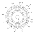
- the three-phase electric motor 22 includes a stator 22S having teeth Te that are formed inwardly on the inner peripheral surface to form a slot SL, and an inner peripheral side of the stator 22S. And an 8-pole surface magnet type rotor 22R having a permanent magnet PM disposed on the surface thereof so as to be rotatably opposed to the teeth Te.
- the first three-phase motor winding L1 and the second three-phase motor winding L1 which are the same phase with respect to the rotor magnet in the two systems shown in FIG. Two three-phase motor windings L2 are wound.
- the first three-phase motor winding L1 is star-connected by connecting one end of each of U-phase coils U1a and U1b, V-phase coils V1a and V1b, and W-phase coils W1a and W1b.
- U-phase coils U1a and U1b, the V-phase coils V1a and V1b, and the W-phase coils W1a and W1b are connected to the motor control device 25, and motor drive currents I1u, I1v, and I1w are individually supplied. .
- the second three-phase motor winding L2 is star-connected by connecting one end of each of U-phase coils U2a and U2b, V-phase coils V2a and V2b, and W-phase coils W2a and W2b. Furthermore, the other ends of the U-phase coils U2a and U2b, the V-phase coils V2a and V2b, and the W-phase coils W2a and W2b are connected to the motor control device 25, and motor drive currents I2u, I2v, and I2w are individually supplied.
- phase coil portions U1a, U1b, V1a, V1b and W1a, W1b of the first three-phase motor winding L1 and the phase coil portions U2a, U2b, V2a, V2b of the second three-phase motor winding L2 and W2a and W2b are wound around slots SL sandwiching the teeth Te so that the directions of the energization currents are the same.
- phase coil portions U1a, U1b, V1a, V1b and W1a, W1b of the first three-phase motor winding L1 and the phase coil portions U2a, U2b, V2a, of the second three-phase motor winding L2, V2b and W2a and W2b are wound around 12 different teeth Te1 to Te12.
- phase coils U1a, U1b, V1a, V1b and W1a, W1b, which are the first system are sequentially wound around the 12 teeth Te1 to Te12 in the same winding direction in the clockwise direction, and then the second system
- the phase coils U2a, U2b, V2a, V2b and W2a, W2b are wound in the same winding direction in the clockwise direction.
- the phase coils U1a, U1b, V1a, V1b and W1a, W1b which are the first system are wound in the same winding direction in the clockwise direction, and finally, the phase coils U2a, U2b, V2a which are the second system.
- each coil part of the first three-phase motor winding L1 and each coil part of the second three-phase motor winding L2 constitute a magnetic circuit that minimizes mutual magnetic interference. .
- the three-phase electric motor 22 includes a rotational position sensor 23a configured from a resolver that detects the rotational position of the rotor.
- the detection value from the rotational position sensor 23a is supplied to the motor electrical angle detection circuit 23, and the motor electrical angle detection circuit 23 detects the motor electrical angle ⁇ m.
- the rotational position sensor 23a is not limited to the resolver, and may be composed of other sensors such as a rotary encoder. Further, the rotational position sensor 23a may be hereinafter referred to as “resolver 23a”.
- the motor control device 25 receives the steering torque T detected by the torque sensor 13 and the vehicle speed Vs detected by the vehicle speed sensor 26 and the motor electrical angle ⁇ m output from the motor electrical angle detection circuit 23.
- a direct current is input to the motor control device 25 from a battery 27 as a direct current source.
- the negative electrode of the battery 27 is grounded, and the positive electrode thereof is connected to the motor control device 25 via an ignition switch 28 (hereinafter sometimes referred to as “IGN switch 28”) for starting the engine, and IGN. It is directly connected to the motor control device 25 without going through the switch 28.
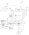
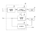
- the specific configuration of the motor control device 25 is configured as shown in FIG. That is, the motor control device 25 includes a control calculation device 31 for calculating a motor current command value, and first and second motor drive circuits 32A to which motor current command values output from the control calculation device 31 are individually input. And 32B, and the first and second three-phase motor windings L1 and L2 of the three-phase electric motor 22 and the first and second motor drive circuits 32A and 32B. 1 and second motor current cut-off circuits 33A and 33B.
- the control arithmetic unit 31 receives the steering torque T detected by the torque sensor 13 and the vehicle speed Vs detected by the vehicle speed sensor 26 shown in FIG. As shown, the motor electrical angle ⁇ m output from the motor electrical angle detection circuit 23 is input. Further, the motor current I1m (output from the coils of the respective phases of the first three-phase motor winding L1 and the second three-phase motor winding L2 of the three-phase electric motor 22 output from the current detection circuits 34A and 34B ( I1mu, I1mv, I1mw) and I2m (I2mu, I2mv, I2mw) are input.
- the detected value may be described as “motor current detected value Im (Imu, Imv, Imw)”.
- the control arithmetic unit 31 includes a voltage provided between the first and second motor drive circuits 32A and 32B and the first and second motor current cutoff circuits 33A and 33B.
- Motor phase voltages V1m (V1mu, V1mv, V1mw) and V2m (V2mu, V2mv, V2mw) detected by the detection circuits 40A and 40B are input.
- the detected value may be described as “motor voltage detected value Vm (Vmu, Vmv, Vmw)”.
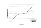
- the control arithmetic unit 31 when the first and second motor drive circuits 32A and 32B are normal, refer to the normal-time steering auxiliary current command value calculation map shown in FIG. 6 set in advance based on the steering torque T and the vehicle speed Vs. Then, steering assist current command values I1 * and I2 * are calculated. Further, in the control arithmetic unit 31, when the first and second motor drive circuits 32A or 32B are abnormal, the abnormal-time steering auxiliary current command value calculation map shown in FIG. 7 preset based on the steering torque T and the vehicle speed Vs is shown. , Steering assist current command values I1 * and I2 * are calculated.
- the target d-axis current command value Id * and the target q-axis current command value in the dq coordinate system based on the calculated steering assist current command values I1 * and I2 * and the motor electrical angle ⁇ m. Iq * is calculated.
- the control arithmetic unit 31 converts the calculated d-axis current command value Id * and q-axis current command value Iq * into dq-phase to three-phase to convert the U-phase current command value Iu * , the V-phase current command value Iv *, and W-phase current command value Iw * is calculated.
- the control arithmetic unit 31 then calculates the U-phase current command value Iu * , the V-phase current command value Iv *, the W-phase current command value Iw *, and the current detection values detected by the current detection circuits 34A and 34B for each phase. Current deviations ⁇ Iu, ⁇ Iv, and ⁇ Iw from the added value are calculated. Still further, the control arithmetic unit 31 performs, for example, a PI control calculation or a PID control calculation on the calculated current deviations ⁇ Iu, ⁇ Ib, and ⁇ Iw, and performs a three-phase voltage command value V1 for the first and second motor drive circuits 32A and 32B. * And V2 * are calculated. Then, the calculated three-phase voltage command values V1 * and V2 * are output to the first and second motor drive circuits 32A and 32B.
- control arithmetic device 31 is provided between the first and second motor current cutoff circuits 33A and 33B and the first and second three-phase motor windings L1 and L2 of the three-phase electric motor 22.
- Motor current detection values I1mu, I1mv, I1mw and I2mu, I2mv, I2mw detected by the first and second abnormality detection circuits 35A and 35B are input.
- the control arithmetic unit 31 compares the input motor current detection values I1mu to I1mw and I2mu to I2mw with the respective phase current command values Iu * , Iv * and Iw * calculated by itself.
- an abnormality detection unit 31a for detecting open failures and short-circuit failures of field effect transistors (FETs) Q1 to Q6 as switching elements constituting first and second inverter circuits 42A and 42B described later is provided. I have.
- the first and second motors that have detected an abnormality when detecting an open failure or a short failure of the field effect transistors (FETs) constituting the first and second inverter circuits 42A and 42B.
- An abnormality detection signal SAa or SAb having a logical value “1” is output to the gate drive circuit 41A or 41B of the drive circuit 32A or 32B.
- Each of the first and second motor drive circuits 32A and 32B includes a gate drive circuit 41A and 41B having an abnormal current control unit 41a, and first and second inverter circuits 42A and 42B.
- the gate drive circuits 41A and 41B receive the three-phase voltage command values V1 * and V2 * output from the control arithmetic unit 31.
- a gate signal is formed based on the input three-phase voltage command values V1 * and V2 * .
- the first and second inverter circuits 42A and 42B receive the gate signals output from the gate drive circuits 41A and 41B. Then, a drive current is supplied to the three-phase electric motor 22 based on the input gate signal.
- each of the gate drive circuits 41A and 41B performs a pulse based on the voltage command values V1 * and V2 * and the triangular carrier signal Sc.
- Six gate signals that are width-modulated (PWM) are formed. These gate signals are output to the first and second inverter circuits 42A and 42B.
- the gate drive circuit 41A has three gates with a high level relative to the first motor current cutoff circuit 33A. Output a signal.
- two high-level gate signals are output to the first power cutoff circuit 44A.
- the gate drive circuit 41A is configured to provide three low-level gates with respect to the first motor current cutoff circuit 33A by the abnormal current control unit 41a. Simultaneously outputs signals and cuts off motor current. In addition, two low-level gate signals are simultaneously output to the first power cut-off circuit 44A to cut off battery power.
- the gate drive circuit 41B has three high levels with respect to the second motor current cutoff circuit 33B. Outputs a gate signal. In addition, two high-level gate signals are output to the second power cutoff circuit 44B. Further, when the abnormality detection signal SAb is a logical value “1” (abnormal), the gate drive circuit 41B has three low-level gates with respect to the second motor current cutoff circuit 33B in the abnormal current control unit 41a. Simultaneously outputs signals and cuts off motor current. In addition, two low-level gate signals are simultaneously output to the second power cutoff circuit 44B to cut off the battery power.
- first and second inverter circuits 42A and 42B the battery current of the battery 27 is input via the noise filter 43 and the first and second power shut-off circuits 44A and 44B, and smoothing electrolysis is performed on the input side.
- Capacitors CA and CB are connected.
- These first and second inverter circuits 42A and 42B have field effect transistors (FETs) Q1 to Q6 as six switching elements, and three switching arms SAu in which two field effect transistors are connected in series. It has a configuration in which SAv and SAw are connected in parallel.
- the gate signals output from the gate drive circuits 41A and 41B are input to the gates of the field effect transistors Q1 to Q6.
- the U-phase current Iu, the V-phase current Iv, and the W-phase current Iw pass through the first and second motor current cutoff circuits 33A and 33B from between the field effect transistors of the switching arms SAu, SAv, and SAw. It is output to the first and second three-phase motor windings L1 and L2 of the electric motor 22.
- the voltage across the shunt resistor inserted between the switching arms SAu, SAv and SAw of the first and second inverter circuits 42A and 42B and the ground is input to the current detection circuits 34A and 34B.
- the These current detection circuits 34A and 34B detect motor currents I1m (I1mu to I1mw) and I2m (I2mu to I2mw).
- the first motor current cut-off circuit 33A has three current cut-off field effect transistors QA1, QA2, and QA3.
- the source of the field effect transistor QA1 is connected to the connection point between the field effect transistors Q1 and Q2 of the switching arm SAu of the first inverter circuit 42A, and the drain is connected to the first three-phase motor winding via the first abnormality detection circuit 35A. It is connected to U-phase coils U1a and U1b of line L1.
- the source of the field effect transistor QA2 is connected to the connection point of the field effect transistors Q3 and Q4 of the switching arm SAv of the first inverter circuit 42A, and the drain is connected to the first three-phase via the first abnormality detection circuit 35A.
- the motor winding L1 is connected to the V-phase coils V1a and V1b.
- the source of the field effect transistor QA3 is connected to the connection point of the field effect transistors Q5 and Q6 of the switching arm SAw of the first inverter circuit 42A, and the drain is connected to the first three-phase via the first abnormality detection circuit 35A.
- the motor winding L1 is connected to the W-phase coils W1a and W1b.
- the second motor current cut-off circuit 33B has three current cut-off field effect transistors QB1, QB2, and QB3.
- the source of the field effect transistor QB1 is connected to the connection point between the field effect transistors Q1 and Q2 of the switching arm SBu of the second inverter circuit 42B, and the drain is connected to the second three-phase motor winding via the second abnormality detection circuit 35B. It is connected to U-phase coils U2a and U2b of line L2.
- the source of the field effect transistor QB2 is connected to the connection point of the field effect transistors Q3 and Q4 of the switching arm SBv of the second inverter circuit 42B, and the drain is connected to the second three-phase via the first abnormality detection circuit 35A.
- the motor winding L2 is connected to the V phase coils V2a and V2b. Further, the source of the field effect transistor QB3 is connected to the connection point of the field effect transistors Q5 and Q6 of the switching arm SBw of the second inverter circuit 42B, and the drain is connected to the second three-phase via the first abnormality detection circuit 35A. The motor winding L2 is connected to the W-phase coils W2a and W2b.
- the field effect transistors QA1 to QA3 and QB1 to QB3 of the first and second motor current cut-off circuits 33A and 33B have the cathodes of the respective parasitic diodes D as the first and second inverter circuits 42A and 42B, respectively. Connected in the same direction.
- Each of the first and second power cutoff circuits 44A and 44B has a series circuit configuration in which two field effect transistors (FETs) QC1, QC2 and QD1, QD2 connect the drains and the parasitic diodes are reversed.
- FETs field effect transistors
- the sources of the field effect transistors QC1 and QD1 are connected to each other and connected to the output side of the noise filter 43. Further, the sources of the field effect transistors QC2 and QD2 are connected to the sources of the field effect transistors Q1, Q2 and Q3 of the first and second inverter circuits 42B and 42B.
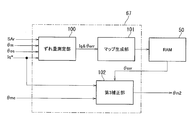
- the motor electrical angle detection circuit 23 of the first embodiment includes a main motor electrical angle detection circuit 23b, a sub motor electrical angle detection circuit 23c, an electrical angle selection unit 23d, a RAM 50, and a ROM 51.
- the main motor electrical angle detection circuit 23 b includes an angle calculation unit 60 and a resolver abnormality diagnosis unit 61.
- the angle calculation unit 60 calculates the first motor electrical angle ⁇ m1 based on the sin signal and the cos signal corresponding to the rotation angle of the three-phase electric motor 22 output from the resolver 23a. Then, the calculated first motor electrical angle ⁇ m1 is output to the electrical angle selector 23d.
- the resolver abnormality diagnosis unit 61 detects an abnormality of the resolver 23a and outputs an abnormality detection signal SAr.
- the sub-motor electrical angle detection circuit 23c outputs the output shaft rotation angle ⁇ os output from the output side rotation angle sensor 13c, the steering torque T, and the IGN switch 28.
- An ignition signal IGN indicating ON / OFF of the ignition is input.
- the first motor electrical angle ⁇ m1 from the angle calculation unit 60 and the abnormality detection signal SAr from the resolver abnormality diagnosis unit 61 are input.
- the sub motor electrical angle detection circuit 23 c includes a relative offset amount estimation unit 62 and a motor electrical angle estimation unit 63.
- the relative offset amount estimation unit 62 estimates the relative offset amount ⁇ off between the origin ⁇ md of the motor electrical angle ⁇ m (hereinafter sometimes referred to as “motor electrical angle origin ⁇ md”) and the reference value ⁇ osr of the output shaft rotation angle ⁇ os. To do. Then, the estimated relative offset amount ⁇ off is output to the motor electrical angle estimation unit 63.
- the motor electrical angle estimator 63 reads from the ROM 51 the previously stored reduction ratio RGr of the reduction gear 21 and the pole pair number P of the rotor 22R of the three-phase electric motor 22.
- the motor electrical angle The estimated value ⁇ me is calculated. Further, the calculated motor electrical angle estimated value ⁇ me is output as the second motor electrical angle ⁇ m2 to the electrical angle selector 23d.
- the motor electrical angle estimation unit 63 calculates the motor electrical angle estimated value ⁇ me according to the following equation (1).
- ⁇ me ⁇ os ⁇ RGr ⁇ P + ⁇ off (1) That is, the motor electrical angle estimated value ⁇ me is calculated by multiplying the output shaft rotation angle detection value ⁇ os by the reduction ratio RGr and the pole pair number P, and adding the relative offset amount ⁇ off to the multiplication result.
- the electrical angle selection unit 23d is configured to detect the main motor electrical angle detection circuit 23b. The first motor electrical angle ⁇ m1 output from is selected.
- the selected first motor electrical angle ⁇ m1 is output as the motor electrical angle ⁇ m to the control arithmetic unit 31 described above.
- the abnormality detection signal SAr is a logical value “1” indicating that there is an abnormality
- the second motor electrical angle ⁇ m2 output from the sub motor electrical angle detection circuit 23c is selected.
- the selected second motor electrical angle ⁇ m2 is output to the control arithmetic unit 31 as the motor electrical angle ⁇ m.
- the relative offset amount estimation unit 62 of the first embodiment includes a first relative offset amount estimation unit 70, a second relative offset amount estimation unit 71, and a relative offset amount selection unit 72.
- the first relative offset amount estimation unit 70 is detected by the output shaft rotation angle detection value ⁇ os detected by the output side rotation angle sensor 13c and the main motor electrical angle detection circuit 23b when the resolver 23a and the angle calculation unit 60 are normal.
- the first relative offset amount ⁇ off1 is estimated based on the detected motor electrical angle detected value ⁇ m1. Then, the estimated first relative offset amount ⁇ off1 is stored in the RAM 50.
- the origin ⁇ md of the motor electrical angle is known, so that the relative offset amount with respect to the reference value ⁇ osr of the output shaft rotation angle can be easily estimated.
- the reference value ⁇ osr is obtained by multiplying the detected value of the output shaft rotation angle when the system is started (when the IGN switch 28 is turned from OFF) by the pole pair number P and the reduction ratio RGr.
- the motor electrical angle origin ⁇ md (0 degree) coincide with the reference value ⁇ osr of the output shaft rotation angle. For example, as shown in FIG.
- the second relative offset amount estimation unit 71 receives the abnormality detection signal SAr in the initial diagnosis by the resolver abnormality diagnosis unit 61 when the system is restarted after the system stop when the ignition switch is turned off and the IGN switch 28 is turned on again. When the value indicates that there is an abnormality, the second relative offset amount ⁇ off2 is estimated. Then, the estimated second relative offset amount ⁇ off2 is stored in the RAM 50.
- the resolver 23a when the resolver 23a has failed at the time of the previous system startup, or when the resolver 23a has failed during the system stop, for example, an abnormality is diagnosed by the initial diagnosis at the time of the current system startup. In this case, all the angle data and the like obtained at the previous system startup are lost. Further, the driver may operate the steering wheel 11 while the system is stopped. Accordingly, when an abnormality is diagnosed when the system is restarted, it is necessary to estimate the motor electrical angle origin ⁇ md and to estimate the second relative offset amount ⁇ off2 based on the estimated motor electrical angle origin ⁇ md.
- the second relative offset amount estimation unit 71 of the first embodiment first stores the current steering torque T detected by the torque sensor 13 at the time of system restart in the RAM 50 as the torque offset amount Toff.
- a current output command Ioi (information on the assumed angle X degrees) is input so that a step-wave motor driving current corresponding to X degrees is input to the three-phase electric motor 22. Is output to the control arithmetic unit 31.
- the control arithmetic unit 31 of the first embodiment inputs a step-wave motor driving current corresponding to the assumed angle X degrees to the three-phase electric motor 22 in response to the input of the current output command Ioi from the sub motor electrical angle detection circuit 23c. Is configured to do.
- the second relative offset amount estimation unit 71 acquires the steering torque T detected by the torque sensor 13 in accordance with the input of the step-wave motor driving current to the three-phase electric motor 22.
- the second relative offset amount estimation unit 71 subtracts the torque offset amount Toff from the acquired steering torque T.
- this offset amount is stored in advance as a torque offset amount Toff and subtracted from the actual steering torque T.
- the second relative offset amount estimation unit 71 determines the symmetry of the torque waveform composed of the steering torque Tc after subtracting the torque offset amount Toff. In the first embodiment, it is determined whether the amplitudes are positive and negative and are equal. When it is determined that the amplitude is positive and negative, the motor electrical angle ⁇ m at that time can be estimated to be the assumed X degree.
- the motor electrical angle ⁇ m at that time can be estimated as the assumed X degree. That is, when the assumed angle X and the current motor electrical angle ⁇ m of the three-phase electric motor 22 match, an output according to the torque command value is obtained.
- the motor electrical angle ⁇ m at that time is not the assumed X degree. judge. For example, when torque waveforms shown in FIG. 11C are obtained with different positive and negative amplitude waveforms with respect to the torque command shown in FIG. It can be determined that it is not.
- the second relative offset amount estimator 71 shifts the current initial position from either the 0 degree side or the 360 degree side with respect to the assumed angle X degree from the shape of the torque waveform having positive and negative amplitudes. Judge whether there is. Since this deviation direction is understood from the waveform shape (asymmetry), the assumed angle X degrees is updated to a value that reduces the deviation, and then the stepped motor drive current corresponding to the updated assumed angle X degrees is obtained. A current output command Ioi is output to the control arithmetic unit 31 so as to be input to the three-phase electric motor 22. Such processing is repeatedly executed until it is determined that the amplitude of the torque waveform is positive and negative and equal.
- the relative offset amount selection unit 72 selects the first relative offset amount ⁇ off1 when the abnormality detection signal SAr becomes a value indicating that there is an abnormality during the system startup, and the abnormality detection signal is detected in the initial diagnosis after the system is restarted.
- SAr becomes a value indicating that there is an abnormality
- the second relative offset amount ⁇ off2 is selected. Then, the selected one of the first relative offset amount ⁇ off1 and the second relative offset amount ⁇ off2 is read from the RAM 50, and is output to the motor electrical angle estimator 63 as the relative offset amount ⁇ off.
- the control arithmetic unit 31 and the motor electrical angle detection circuit 23 are activated, and various processes such as a motor electrical angle ⁇ m detection process and a steering assist control process are started. At this time, it is assumed that the resolver 23a and the angle calculation unit 60 are normal.
- the abnormality detection signal SAr becomes a value indicating that there is no abnormality
- the electrical angle selection unit 23d outputs the first motor electrical angle ⁇ m1 calculated by the angle calculation unit 60 to the control arithmetic unit 31 as the motor electrical angle ⁇ m.
- the control arithmetic unit 31 calculates the d-axis current command value Id * and the q-axis current command value Iq * based on the motor electrical angle ⁇ m.
- phase voltage command values V1 * and V2 * are output to the first and second motor drive circuits 32A and 32B.
- the first and second inverter circuits 42A and 42B are driven and controlled by the first and second motor drive circuits 32A and 32B, and the three-phase electric motor 22 is driven (commutation controlled).
- the relative offset amount estimation unit 62 of the sub motor electrical angle detection circuit 23c performs the process of estimating the first relative offset amount ⁇ off1. That is, based on the output shaft rotation angle detection value ⁇ os detected by the normal output side rotation angle sensor 13c and the motor electrical angle ⁇ m output from the main motor electrical angle detection circuit 23b, the first relative offset amount ⁇ off1 is calculated.
- the estimated first relative offset amount ⁇ off1 is stored in the RAM 50.
- the relative offset amount estimation unit 62 of the first embodiment uses the first relative offset amount ⁇ off1 stored in the RAM 50 as the relative offset amount ⁇ off when the resolver 23a and the angle calculation unit 60 are normal. Output to.
- the motor electrical angle estimation unit 63 When the resolver 23a and the angle calculation unit 60 are normal, the motor electrical angle estimation unit 63 outputs the output shaft rotation angle detection value ⁇ os detected by the output side rotation angle sensor 13c, the first relative offset amount ⁇ off1, and the reduction ratio.
- a motor electrical angle estimated value ⁇ me is calculated from RGr (for example, 20.5) and a magnetic pole pair (for example, 4). Then, the estimated motor electrical angle ⁇ me is output to the electrical angle selector 23d as the second motor electrical angle ⁇ m2.
- the electrical angle selection unit 23d receives a signal from the sub motor electrical angle detection circuit 23c.
- the input second motor electrical angle ⁇ m2 is output to the control arithmetic unit 31 as the motor electrical angle ⁇ m.
- the three-phase electric motor 22 is driven and controlled (commutation control) based on the second motor electrical angle ⁇ m2 estimated by the sub motor electrical angle detection circuit 23c.
- the IGN switch 28 is once turned off to stop the system, and then the IGN switch 28 is turned on again to restart the system.
- the abnormality detection signal SAr becomes a value indicating that there is an abnormality by the initial diagnosis by the resolver abnormality diagnosis unit 61 after the system is restarted, and the relative offset amount estimation unit 62 performs the estimation process of the second relative offset amount ⁇ off2.
- the relative offset amount estimation unit 62 first acquires the steering torque T after the initial diagnosis and stores it in the RAM 50 as the torque offset amount Toff. Subsequently, the initial value of the assumed angle X is set to 180 degrees here, and a current output command Ioi is output to the control arithmetic unit 31 so that a step-wave motor driving current corresponding to 180 degrees is input to the three-phase electric motor 22. . As a result, a step-wave motor driving current corresponding to 180 degrees flows through the three-phase electric motor 22.
- the steering torque T detected by the torque sensor 13 is acquired in response to the input of the step-wave motor driving current, the torque offset amount Toff is subtracted from the steering torque T, and the torque waveform of the steering torque Tc after the subtraction is obtained.
- Determine symmetry it is assumed that it is determined to be asymmetric.
- the second relative offset amount estimation unit 71 determines the deviation direction from the shape of the asymmetric torque waveform, and updates the assumed angle X in a direction in which the deviation becomes smaller.
- the response waveform of 180 degrees is shifted in the direction of 360 degrees with respect to 0 degrees. Update to the intermediate value of 90 degrees. Then, a step-wave motor driving current corresponding to 90 degrees is input to the three-phase electric motor 22, and the symmetry of the torque waveform is determined again from the response torque. In this case, since the 90-degree response waveform is shifted in the direction of 360 degrees with respect to 0 degrees, the process of updating the assumed angle X to 45 degrees, which is an intermediate value between 0 degrees and 90 degrees, is performed. Repeat until the positive and negative amplitudes of the torque waveforms are equal.
- the assumed angle X when they are equal is the motor electrical angle origin ⁇ md. It is not limited to the case where the amplitudes are completely the same. For example, it may be determined that the amplitudes are equal when the difference between the positive and negative amplitudes is within a preset error range.
- the relative offset amount estimation unit 62 calculates a second relative offset amount ⁇ off2 from the estimated motor electrical angle origin ⁇ md and the reference value ⁇ osr of the output shaft rotation angle detection value acquired when the system is restarted. Then, the calculated second relative offset amount ⁇ off2 is stored in the RAM 50.
- the relative offset amount estimation unit 62 reads the second relative offset amount ⁇ off2 from the RAM 50 because the abnormality detection signal SAr has a value indicating that there is an abnormality at the time of system restart, and the read second relative offset amount.
- ⁇ off2 is output to the motor electrical angle estimation unit 63 as a relative offset amount ⁇ off.
- the motor electrical angle estimation unit 63 outputs the output shaft rotation angle detection value ⁇ os detected by the output side rotation angle sensor 13c, the second relative offset amount ⁇ off2, and the reduction ratio RGr (for example, 20.5). Then, the motor electrical angle estimated value ⁇ me is calculated from the magnetic pole pair (for example, 4).
- the calculated motor electrical angle estimated value ⁇ me is output to the electrical angle selector 23d as the second motor electrical angle ⁇ m2. Since the abnormality detection signal SAr has a value indicating that there is an abnormality, the electrical angle selection unit 23d sets the second motor electrical angle ⁇ m2 input from the sub motor electrical angle detection circuit 23c as the motor electrical angle ⁇ m to the control arithmetic device 31. Output.
- the three-phase electric motor 22 is driven and controlled (commutation control) based on the second motor electrical angle ⁇ m2 estimated by the sub motor electrical angle detection circuit 23c.
- the relative offset amount estimation unit 62 corresponds to the offset amount estimation unit
- the motor electrical angle estimation unit 63 corresponds to the motor electrical angle estimation unit
- the control arithmetic device 31 and the motor electrical angle detection circuit 23 include the motor drive control unit.
- the torque sensor 13 corresponds to a torque detector
- the output side rotation angle sensor 13c corresponds to a steering angle detector
- the three-phase electric motor 22 corresponds to a multiphase electric motor
- the resolver 23a and the angle calculator 60 Corresponds to the motor electrical angle detector.
- the first and second inverter circuits 42A and 42B correspond to the motor drive circuit
- the control arithmetic device 31 corresponds to the control arithmetic device
- the resolver abnormality diagnosis unit 61 corresponds to the abnormality diagnosis unit
- the RAM 50 stores the memory.
- the relative offset amount ⁇ off between the angle reference value ⁇ osr and the motor electrical angle origin ⁇ md of the three-phase electric motor 22 that generates the steering assist force is estimated.
- the motor electrical angle estimator 63 estimates the motor electrical angle ⁇ m based on the output shaft rotation angle ⁇ os and the relative offset amount ⁇ off.
- the control arithmetic unit 31 and the motor electrical angle detection circuit 23 drive-control the three-phase electric motor 22 based on the first motor electrical angle ⁇ m1 detected by the resolver 23a and the angle calculation unit 60 when they are normal.
- the three-phase electric motor 22 is driven and controlled based on the second motor electrical angle ⁇ m2 estimated by the motor electrical angle estimation unit 63.
- the relative offset amount ⁇ off between the reference value ⁇ osr of the output shaft rotation angle ⁇ os detected by the output side rotation angle sensor 13c and the motor electrical angle origin ⁇ md of the three-phase electric motor 22 is estimated, and the output shaft rotation The motor electrical angle ⁇ m can be estimated based on the angle ⁇ os and the relative offset amount ⁇ off.
- the three-phase electric motor 22 can be driven and controlled based on the estimated motor electrical angle ⁇ m. As a result, even when at least one of the resolver 23a and the angle calculation unit 60 is abnormal, the three-phase electric motor 22 can be continuously driven.
- the torque sensor 13 detects the steering torque T transmitted to the steering mechanism.
- the output side rotation angle sensor 13c detects the steering angle (output shaft rotation angle ⁇ os) of the steering.
- a three-phase electric motor 22 generates a steering assist force.
- the resolver 23 a and the angle calculation unit 60 detect the motor electrical angle ⁇ m of the three-phase electric motor 22.
- the first and second inverter circuits 42 ⁇ / b> A and 42 ⁇ / b> B supply drive current to the three-phase electric motor 22.
- the control arithmetic device 31 drives and controls the first and second inverter circuits 42A and 42B based on the steering torque T detected by the torque sensor 13 and the motor electrical angle ⁇ m detected by the resolver 23a and the angle calculator 60.
- the resolver abnormality diagnosis unit 61 diagnoses abnormality of the resolver 23a and the angle calculation unit 60.
- the relative offset amount estimation unit 62 estimates the relative offset amount ⁇ off between the output shaft rotation angle reference value ⁇ osr and the motor electrical angle origin ⁇ md.
- the motor electrical angle estimation unit 63 estimates the motor electrical angle ⁇ m based on the output shaft rotation angle ⁇ os detected by the output side rotation angle sensor 13 c and the relative offset amount ⁇ off estimated by the relative offset amount estimation unit 62.
- the control arithmetic unit 31 estimates the steering torque T detected by the torque sensor 13 and the motor electrical angle estimation unit 63.
- the first and second inverter circuits 42A and 42B are driven and controlled based on the two motor electrical angles ⁇ m2.
- the relative offset amount ⁇ off between the reference value ⁇ osr of the output shaft rotation angle ⁇ os detected by the output side rotation angle sensor 13c and the motor electrical angle origin ⁇ md of the three-phase electric motor 22 is estimated, and the output shaft rotation The motor electrical angle ⁇ m can be estimated based on the angle ⁇ os and the relative offset amount ⁇ off.
- the relative offset amount estimation unit 62 determines the output shaft rotation angle ⁇ os detected by the output-side rotation angle sensor 13c when the resolver 23a and the angle calculation unit 60 are normal.
- the first relative offset amount ⁇ off1 is estimated based on the resolver 23a and the motor electrical angle ⁇ m detected by the angle calculation unit 60, and the estimated first relative offset amount ⁇ off1 is stored in the RAM 50.
- the motor electrical angle estimator 63 diagnoses at least one of the resolver 23a and the angle calculator 60 as abnormal by the resolver abnormality diagnosis unit 61 during system startup, the output shaft rotation angle ⁇ os detected by the output side rotation angle sensor 13c. And a first relative offset amount ⁇ off1 stored in the RAM 50, the motor electrical angle ⁇ m is estimated.
- the resolver 23a and the angle calculation unit 60 are normal, the output shaft rotation angle ⁇ os detected by the output side rotation angle sensor 13c and the motor electrical angle ⁇ m detected by the resolver 23a and the angle calculation unit 60 are obtained. Based on this, the first relative offset amount ⁇ off1 can be estimated and stored in the RAM 50. As a result, even if an abnormality occurs in at least one of the resolver 23a and the angle calculation unit 60 during system startup, it is possible to estimate an accurate motor electrical angle from the first relative offset amount ⁇ off1 stored in the RAM 50. . This makes it possible to continue to drive the three-phase electric motor 22 even when at least one of the resolver 23a and the angle calculation unit 60 is abnormal during system startup.
- the relative offset amount estimation unit 62 diagnoses that at least one of the resolver 23a and the angle calculation unit 60 is abnormal in the initial diagnosis by the resolver abnormality diagnosis unit 61 at the time of system startup. Then, a motor driving current (for example, stepped motor driving current) that vibrates positively and negatively is passed through the control arithmetic unit 31 and the first and second inverter circuits 42A and 42B to the three-phase electric motor 22, The motor electrical angle origin ⁇ md is estimated based on the amplitude of the steering torque T detected by the torque sensor 13 when the motor drive current is supplied, and the second relative offset amount ⁇ off2 is estimated based on the estimated motor electrical angle origin ⁇ md. .
- a motor driving current for example, stepped motor driving current
- the motor electrical angle estimator 63 diagnoses that at least one of the resolver 23a and the angle calculator 60 is abnormal in the initial diagnosis by the resolver abnormality diagnosis unit 61, the output shaft rotation angle ⁇ os detected by the output side rotation angle sensor 13c The motor electrical angle ⁇ m is estimated based on the second relative offset amount ⁇ off2.
- a motor drive current that vibrates positively and negatively (for example, a step-wave motor drive current) is generated.
- the motor electrical angle origin ⁇ md is estimated based on the amplitude of the steering torque T detected by the torque sensor 13 when this motor driving current is applied to the three-phase electric motor 22, and the first motor electrical angle origin ⁇ md is calculated based on the estimated motor electrical angle origin ⁇ md.
- the relative offset amount ⁇ off2 of 2 can be estimated.
- the motor electrical angle ⁇ m can be estimated based on the second relative offset amount ⁇ off2.
- the phase electric motor 22 can be normally driven.
- the relative offset amount estimation unit 62 uses the steering torque T detected by the torque sensor 13 before estimating the second relative offset amount ⁇ off2 as the torque offset amount Toff.
- the torque offset amount Toff is subtracted from the steering torque T stored in the RAM 50 and detected by the torque sensor 13 when a step-wave motor driving current is passed, and the motor electrical angle origin ⁇ md is based on the amplitude of the steering torque Tc after the subtraction. Is estimated.
- the electric power steering device 3 includes a motor control device 25.
- the same operation and effect as the motor control device 25 described in the above (1) to (5) can be obtained, and the steering assist control can be continued even when the resolver 23a and the angle calculation unit 60 are out of order. Therefore, the reliability of the electric power steering device 3 can be improved.
- the vehicle 1 according to the first embodiment includes the electric power steering device 3 including the motor control device 25.
- the same operation and effect as the motor control device 25 described in the above (1) to (5) can be obtained, and the steering assist control can be continued even when the resolver 23a fails.
- the reliability of the vehicle 1 can be improved.
- the second embodiment is different in that a second sub motor electrical angle detection circuit 23e is provided instead of the sub motor electrical angle detection circuit 23c in the motor electrical angle detection circuit 23 of the first embodiment, and the other points are the same as those of the first embodiment.
- the configuration is the same as that of the embodiment.
- the same components as those in the first embodiment are denoted by the same reference numerals, description thereof will be omitted as appropriate, and different portions will be described in detail.
- the motor electrical angle detection circuit 23 includes a main motor electrical angle detection circuit 23b, a second sub motor electrical angle detection circuit 23e, an electrical angle selection unit 23d, a RAM 50, ROM 51 is provided.
- the second sub motor electrical angle detection circuit 23e has an output shaft rotation angle ⁇ os output from the output side rotation angle sensor 13c, a steering torque T, and an ignition signal IGN indicating ON / OFF of the ignition output from the IGN switch 28. And are entered.
- the second sub motor electrical angle detection circuit 23e includes a relative offset amount estimation unit 62, a motor electrical angle estimation unit 63, and a first estimated angle correction unit 64.
- the motor electrical angle estimator 63 of the second embodiment calculates a motor electrical angle estimated value ⁇ me based on the output shaft rotation angle detection value ⁇ os, the reduction ratio RGr, the number of pole pairs P, and the relative offset amount ⁇ off. Then, the calculated motor electrical angle estimated value ⁇ me is output to the first estimated angle correction unit 64.
- the first estimated angle correction unit 64 corrects the motor electrical angle estimated value ⁇ me based on the back electromotive voltage EMF of the three-phase electric motor 22. Then, the corrected motor electrical angle estimated value is output to the electrical angle selector 23d as the second motor electrical angle ⁇ m2.
- the first estimated angle correction unit 64 includes a back electromotive voltage calculation unit 80, a zero cross timing detection unit 81, an angle error calculation unit 82, and a first correction unit 83.
- mechanical elements such as a reduction gear (worm gear) 21 are interposed between the output side rotation angle sensor 13 c and the three-phase electric motor 22.
- the compliance of the reduction gear (worm gear) 21 has a non-linear characteristic due to backlash and material reasons. In addition, this characteristic changes due to aging, moisture absorption, and temperature change.
- the motor electrical angle ⁇ m does not have a one-to-one correspondence with the output shaft rotation angle ⁇ os, and the error between the estimated motor electrical angle value ⁇ me and the actual motor electrical angle ⁇ m increases as the motor output increases.
- the compliance characteristic of the worm gear has nonlinearity and hysteresis as shown in FIG. In FIG. 14, the X-axis is load torque (motor output torque), and the Y-axis is the deformation amount ⁇ of the motor electrical angle ⁇ m.
- the first estimated angle correction unit 64 corrects the estimated motor electrical angle ⁇ me based on the back electromotive force EMF that is uniquely determined by the motor electrical angle ⁇ m and the motor rotation speed.
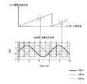
- the counter electromotive voltage calculation unit 80 is based on the motor current detection value Im (Imu, Imv, Imw) and the motor voltage detection value Vm (Vmu, Vmv, Vmw). EMFuv, EMFvw, EMFwu) are calculated. Then, the calculated interphase counter electromotive voltage EMF is output to the zero cross timing detector 81.
- the back electromotive force voltage EMF between the UV phase is the back electromotive voltage EMFuv between the U phase and the V phase, the back electromotive force voltage EMFvw between the V phase and the W phase, and the WU between the W phase and the U phase. It consists of a phase back electromotive voltage EMFwu and appears as a positive or negative value with 0 as a reference. Specifically, for example, a sine wave having a phase difference of 120 degrees as shown in the lower diagram of FIG. 15 is obtained. In the lower diagram of FIG.
- the zero-cross timing detector 81 detects a zero-cross timing that is a timing at which the UV-phase back electromotive voltage EMFuv, the VW phase back-electromotive voltage EMFvw, and the WU-phase back electromotive voltage EMFwu become zero. Specifically, the point at which the vertical line extending from the end of the upper rhombus in FIG. 15 and the horizontal axis where the vertical axis is 0 is the zero cross point.
- the zero-crossing timing detection unit 81 of the first embodiment has a timing at which the signs of the UV phase back electromotive voltage EMFuv, the VW phase back electromotive voltage EMFvw, and the WU phase back electromotive voltage EMFwu change from negative to positive or from positive to negative. Detect as zero cross timing. Then, the motor electrical angle ⁇ mz corresponding to the detected zero cross timing (zero cross point) is read from the ROM 51, and the read motor electrical angle ⁇ mz is output to the angle error calculation unit 82.
- the motor electrical angle at the zero cross point of the UV phase back electromotive voltage EMFuv, the VW phase back electromotive voltage EMFvw, and the WU phase back electromotive voltage EMFwu is a known value, and therefore, the motor corresponding to each zero cross point.
- the electrical angle ⁇ mz is stored in the ROM 51 in advance.
- the angle error calculation unit 82 calculates the difference between the motor electrical angle ⁇ mz corresponding to the zero cross point input from the zero cross timing detection unit 81 and the motor electrical angle estimation value ⁇ me input from the motor electrical angle estimation unit 63, The calculated difference is stored in the RAM 50 as the angle error ⁇ err.
- the angle error calculation unit 82 updates the angle error ⁇ err stored in the RAM 50 every time zero cross timing is detected.
- the zero cross timing appears six times per cycle (360 degrees) of the motor electrical angle ⁇ m, as shown in the lower diagram of FIG. Accordingly, it is possible to update the angle error ⁇ err with a period of 60 electrical angles.
- the first correction unit 83 corrects the motor electrical angle estimation value ⁇ me input from the motor electrical angle estimation unit 63 with the angle error ⁇ err stored in the RAM 50, and sets the corrected motor electrical angle estimation value to the second value.
- the motor electrical angle ⁇ m2 is output to the electrical angle selector 23d.
- an estimated motor electrical angle value ⁇ me having an error surrounded by a dotted circle corresponding to the zero cross point shown in the lower diagram of FIG. Is corrected by the angle error ⁇ err.
- the motor electrical angle estimated value ⁇ me is corrected by the angle error ⁇ err at each correction timing. That is, the first correction unit 83 performs correction using the angle error ⁇ err currently stored in the RAM 50 until the next zero cross timing is detected.
- the control arithmetic unit 31 and the motor electrical angle detection circuit 23 are activated, and various processes such as a motor electrical angle ⁇ m detection process and a steering assist control process are started.
- various processes such as a motor electrical angle ⁇ m detection process and a steering assist control process are started.
- the resolver 23a and the angle calculation unit 60 are normal.
- the abnormality detection signal SAr becomes a value indicating that there is no abnormality, and the electrical angle selection unit 23d outputs the first motor electrical angle ⁇ m1 calculated by the angle calculation unit 60 to the control arithmetic unit 31 as the motor electrical angle ⁇ m.
- the control arithmetic unit 31 calculates the d-axis current command value Id * and the q-axis current command value Iq * based on the motor electrical angle ⁇ m. Then, based on the d-axis current command value Id * and the q-axis current command value Iq * , three-phase voltage command values V1 * and V2 * for the first and second motor drive circuits 32A and 32B are calculated, and the calculated 3 The phase voltage command values V1 * and V2 * are output to the first and second motor drive circuits 32A and 32B.
- the first and second inverter circuits 42A and 42B are driven and controlled by the first and second motor drive circuits 32A and 32B, and the three-phase electric motor 22 is driven (commutation controlled).
- the relative offset amount estimation unit 62 of the second sub-motor electric angle detection circuit 23e performs an estimation process of the first relative offset amount ⁇ off1. That is, based on the output shaft rotation angle detection value ⁇ os detected by the normal output side rotation angle sensor 13c and the motor electrical angle ⁇ m output from the main motor electrical angle detection circuit 23b, the first relative offset amount ⁇ off1 is calculated.
- the estimated first relative offset amount ⁇ off1 is stored in the RAM 50.
- the relative offset amount estimation unit 62 of the second embodiment uses the first relative offset amount ⁇ off1 stored in the RAM 50 as the relative offset amount ⁇ off when the resolver 23a and the angle calculation unit 60 are normal. Output to.
- the motor electrical angle estimation unit 63 When the resolver 23a and the angle calculation unit 60 are normal, the motor electrical angle estimation unit 63 outputs the output shaft rotation angle detection value ⁇ os detected by the output side rotation angle sensor 13c, the first relative offset amount ⁇ off1, and the reduction ratio.
- a motor electrical angle estimated value ⁇ me is calculated from RGr (for example, 20.5) and a magnetic pole pair (for example, 4). Then, the motor electrical angle estimated value ⁇ me is output to the first estimated angle correction unit 64.
- the first estimated angle correction unit 64 calculates the interphase counter electromotive force EMF (EMFuv, EMFvw, EMFwu) from the motor current detection value Im and the motor voltage detection value Vm, and detects the zero cross timing.
- the motor electrical angle ⁇ mz at the zero cross point is acquired from the ROM 51, and the angle error ⁇ err is calculated from the difference between the motor electrical angle estimated value ⁇ me and the motor electrical angle ⁇ mz. Then, the calculated angle error ⁇ err is overwritten and stored in the RAM 50. Further, the first estimated angle correction unit 64 corrects the estimated motor electrical angle value ⁇ me using the angle error ⁇ err stored in the RAM 50, and outputs the corrected value to the electrical angle selection unit 23d as the second motor electrical angle ⁇ m2.
- the electrical angle selection unit 23d receives a signal from the sub motor electrical angle detection circuit 23c.
- the input second motor electrical angle ⁇ m2 is output to the control arithmetic unit 31 as the motor electrical angle ⁇ m.
- the three-phase electric motor 22 is drive-controlled (commutation control) based on the second motor electrical angle ⁇ m2 estimated by the second sub-motor electrical angle detection circuit 23e.
- the abnormality detection signal SAr becomes a value indicating that there is an abnormality by the initial diagnosis by the resolver abnormality diagnosis unit 61 after the system is restarted, and the relative offset amount estimation unit 62 performs the estimation process of the second relative offset amount ⁇ off2.
- the relative offset amount estimation unit 62 first acquires the steering torque T after the initial diagnosis and stores it in the RAM 50 as the torque offset amount Toff.
- the initial value of the assumed angle X is set to 180 degrees here, and a current output command Ioi is output to the control arithmetic unit 31 so that a step-wave motor driving current corresponding to 180 degrees is input to the three-phase electric motor 22. .
- a step-wave motor driving current corresponding to 180 degrees flows through the three-phase electric motor 22.
- the steering torque T detected by the torque sensor 13 is acquired in response to the input of the step-wave motor driving current, the torque offset amount Toff is subtracted from the steering torque T, and the torque waveform of the steering torque Tc after the subtraction is obtained.
- Determine symmetry it is assumed that it is determined to be asymmetric.
- the second relative offset amount estimation unit 71 determines the deviation direction from the shape of the asymmetric torque waveform, and updates the assumed angle X in a direction in which the deviation becomes smaller. For example, when the actual motor electrical angle ⁇ m is 0 degree, the response waveform of 180 degrees is shifted in the direction of 360 degrees with respect to 0 degrees. Update to the intermediate value of 90 degrees.
- a step-wave motor driving current corresponding to 90 degrees is input to the three-phase electric motor 22, and the symmetry of the torque waveform is determined again from the response torque.
- the process of updating the assumed angle X to 45 degrees, which is an intermediate value between 0 degrees and 90 degrees, is performed. Repeat until the positive and negative amplitudes of the torque waveforms are equal.
- the assumed angle X when they are equal is the motor electrical angle origin ⁇ md. It is not limited to the case where the amplitudes are completely the same. For example, it may be determined that the amplitudes are equal when the difference between the positive and negative amplitudes is within a preset error range.
- the relative offset amount estimation unit 62 calculates a second relative offset amount ⁇ off2 from the estimated motor electrical angle origin ⁇ md and the reference value ⁇ osr of the output shaft rotation angle detection value acquired when the system is restarted. Then, the calculated second relative offset amount ⁇ off2 is stored in the RAM 50.
- the relative offset amount estimation unit 62 reads the second relative offset amount ⁇ off2 from the RAM 50 because the abnormality detection signal SAr has a value indicating that there is an abnormality at the time of system restart, and the read second relative offset amount.
- ⁇ off2 is output to the motor electrical angle estimation unit 63 as a relative offset amount ⁇ off.
- the motor electrical angle estimation unit 63 outputs the output shaft rotation angle detection value ⁇ os detected by the output side rotation angle sensor 13c, the second relative offset amount ⁇ off2, and the reduction ratio RGr (for example, 20.5).
- the motor electrical angle estimated value ⁇ me is calculated from the magnetic pole pair (for example, 4).
- the calculated motor electrical angle estimated value ⁇ me is output to the first estimated angle correction unit 64.
- the first estimated angle correction unit 64 corrects the motor electrical angle estimated value ⁇ me with the angle error ⁇ err similarly to the case where the first relative offset amount ⁇ off1 is used, and the corrected motor electrical angle estimated value is set to the second value. Is output to the electrical angle selector 23d as the motor electrical angle ⁇ m2. Since the abnormality detection signal SAr is a value indicating that there is an abnormality, the electrical angle selection unit 23d uses the second motor electrical angle ⁇ m2 input from the second sub motor electrical angle detection circuit 23e as the motor electrical angle ⁇ m, and performs the control arithmetic unit. To 31. Thereby, in the control arithmetic unit 31, the three-phase electric motor 22 is drive-controlled (commutation control) based on the second motor electrical angle ⁇ m2 estimated by the second sub-motor electrical angle detection circuit 23e.
- the motor electrical angle estimation unit 63 corresponds to the motor electrical angle estimation unit
- the control arithmetic device 31 and the motor electrical angle detection circuit 23 correspond to the motor drive control unit.
- the torque sensor 13 corresponds to a torque detector
- the output side rotation angle sensor 13c corresponds to a steering angle detector
- the three-phase electric motor 22 corresponds to a multiphase electric motor
- the resolver 23a and the angle calculator 60 Corresponds to the motor electrical angle detector.
- the first and second inverter circuits 42A and 42B correspond to the motor drive circuit
- the control arithmetic device 31 corresponds to the control arithmetic device
- the resolver abnormality diagnosis unit 61 corresponds to the abnormality diagnosis unit
- the angle correction unit 64 corresponds to the motor electrical angle correction unit
- the zero cross timing detection unit 81 corresponds to the cross timing detection unit.
- the second embodiment has the following effects in addition to the effects of the first embodiment.
- the motor electrical angle estimation unit 63 detects the output shaft rotation detected by the output side rotation angle sensor 13c that detects the steering angle (output shaft rotation angle ⁇ os) of the steering.
- the motor electrical angle ⁇ m is estimated based on the angle ⁇ os.
- the control arithmetic unit 31 and the motor electrical angle detection circuit 23 drive-control the three-phase electric motor 22 based on the first motor electrical angle ⁇ m1 detected by the resolver 23a and the angle calculation unit 60 when they are normal.
- the three-phase electric motor 22 is based on the second motor electrical angle ⁇ m2 (the value corrected by the first estimated angle corrector 64) estimated by the motor electrical angle estimator 63. Is controlled. With this configuration, it is possible to estimate the motor electrical angle ⁇ m based on the output shaft rotation angle ⁇ os detected by the output side rotation angle sensor 13c. When at least one of the resolver 23a and the angle calculation unit 60 is abnormal, it is possible to drive and control the multiphase electric motor based on the estimated motor electrical angle ⁇ m2. As a result, even when at least one of the resolver 23a and the angle calculation unit 60 is abnormal, the three-phase electric motor 22 can be continuously driven.
- the torque sensor 13 detects the steering torque T transmitted to the steering mechanism.
- the output side rotation angle sensor 13c detects the steering angle (output shaft rotation angle ⁇ os) of the steering.
- a three-phase electric motor 22 generates a steering assist force.
- the resolver 23 a and the angle calculation unit 60 detect the motor electrical angle ⁇ m of the three-phase electric motor 22.
- the first and second inverter circuits 42 ⁇ / b> A and 42 ⁇ / b> B supply drive current to the three-phase electric motor 22.
- the control arithmetic device 31 drives and controls the first and second inverter circuits 42A and 42B based on the steering torque T detected by the torque sensor 13 and the motor electrical angle ⁇ m detected by the resolver 23a and the angle calculator 60.
- the resolver abnormality diagnosis unit 61 diagnoses abnormality of the resolver 23a and the angle calculation unit 60.
- the motor electrical angle estimation unit 63 estimates the motor electrical angle ⁇ m based on the output shaft rotation angle ⁇ os detected by the output side rotation angle sensor 13c.
- the control arithmetic unit 31 estimates the steering torque T detected by the torque sensor 13 and the motor electrical angle estimation unit 63.
- the first and second inverter circuits 42A and 42B are driven and controlled based on the second motor electrical angle ⁇ m2 (the value corrected by the first estimated angle correction unit 64). With this configuration, it is possible to estimate the motor electrical angle ⁇ m based on the output shaft rotation angle ⁇ os detected by the output side rotation angle sensor 13c. When at least one of the resolver 23a and the angle calculation unit 60 is abnormal, it is possible to drive and control the multiphase electric motor based on the estimated motor electrical angle ⁇ m2. As a result, even when at least one of the resolver 23a and the angle calculation unit 60 is abnormal, the three-phase electric motor 22 can be continuously driven.
- the first estimated angle correction unit 64 corrects the motor electrical angle estimated value ⁇ me based on the back electromotive voltage EMF of the three-phase electric motor 22.
- the zero cross timing detection unit 81 detects the timing at which the back electromotive voltage waveform of each phase of the three-phase electric motor 22 zero-crosses.
- the motor electric angle estimated value ⁇ me is corrected based on the motor electric angle information corresponding to the zero cross point.
- the electric power steering device 3 according to the second embodiment includes a motor control device 25.
- a motor control device 25 With this configuration, the same operation and effect as the motor control device 25 described in the above (1) to (4) can be obtained, and the steering assist control can be continued even when the resolver 23a and the angle calculation unit 60 are out of order. Therefore, the reliability of the electric power steering device 3 can be improved.
- the vehicle 1 according to the second embodiment includes the electric power steering device 3 including the motor control device 25.
- the same operation and effect as the motor control device 25 described in the above (1) to (4) can be obtained, and the steering assist control can be continued even when the resolver 23a fails.
- the reliability of the vehicle 1 can be improved.
- the third embodiment is different in that a second estimated angle correction unit 65 is provided in place of the first estimated angle correction unit 64 in the second sub-motor electric angle detection circuit 23e of the second embodiment, and the others are the above.
- the configuration is the same as in the second embodiment.
- the same components as those in the second embodiment will be denoted by the same reference numerals, description thereof will be omitted as appropriate, and different portions will be described in detail.
- the second estimated angle correction unit 65 of the third embodiment includes a back electromotive voltage calculation unit 80, a switching timing detection unit 84, an angle error calculation unit 82, and a first correction unit 83.
- a switching timing detection unit 84 is provided instead of the zero cross timing detection unit 81 of the first estimated angle correction unit 64 of the second embodiment. It becomes the same composition as.
- the switching timing detection unit 84 has a set of a magnitude relationship between the amplitude (absolute value) of each phase back electromotive voltage waveform and a sign relationship between each phase back electromotive voltage value when the three-phase electric motor 22 rotates in the positive and negative directions. Timing of switching to another set of magnitude relationship and code relationship is detected.
- the interphase counter electromotive voltage waveform shown in FIGS. The relation and the sign relation are constant.
- the solid line indicates the UV phase counter electromotive voltage EMFuv
- the broken line indicates the VW phase counter electromotive voltage EMFvw
- the alternate long and short dash line indicates the WU phase counter electromotive voltage EMFwu.
- the back electromotive voltage EMFvw between VW phases becomes the largest (“large” in FIG. 17B)
- the back electromotive voltage EMFwu between WU phases becomes It becomes the second largest (“middle” in FIG. 17B)
- the UV phase back electromotive voltage EMFuv becomes the smallest (“small” in FIG. 17B).
- the magnitude relation is the same as the range of the motor electrical angle of 0 to 30 degrees. That is, the same magnitude relationship appears twice in the motor electrical angle range of 0 to 360 degrees. This is the same for other magnitude relationships, and the same magnitude relationship appears twice when the motor rotation direction is negative.
- the UV phase back electromotive voltage EMFuv is “+”
- the VW phase back electromotive voltage EMFvw is “ ⁇ ”
- the WU phase back electromotive force is The voltage EMFwu becomes “+”.
- the UV phase back electromotive voltage EMFuv is “ ⁇ ”
- the VW phase back electromotive voltage EMFvw is “+”
- the WU phase back electromotive voltage EMFwu is “ ⁇ ”.
- the motor electrical angle at the boundary position at the moment when the current magnitude relation and sign relation set switches to another magnitude relation and sign relation set is the current motor electrical angle ⁇ m.
- the estimated motor electrical angle ⁇ me is corrected using the motor electrical angle ⁇ m. For example, when the magnitude relation and sign relation set corresponding to the angle range of 60 degrees to 90 degrees is switched to the magnitude relation and sign relation set corresponding to the angle range of 90 degrees to 120 degrees, the current motor electrical The angle ⁇ m is 90 degrees. In addition, for example, when switching from a set of magnitude relationship and sign relationship corresponding to an angle range of 120 degrees to 150 degrees to a set of magnitude relationship and sign relationship corresponding to an angle range of 90 degrees to 120 degrees, The motor electrical angle ⁇ m is 120 degrees.
- map data of a set of amplitude relations of the back electromotive voltage waveforms between phases and sign relations of back electromotive voltage values between the phases shown in FIGS. 17B and 17D is stored in the ROM 51 in advance.
- the switching timing detection unit 84 calculates the motor electrical angle ⁇ m (hereinafter sometimes referred to as “motor electrical angle ⁇ mc”) corresponding to the motor rotation direction and the set of magnitude relationship and sign relationship before and after the switching timing.
- motor electrical angle ⁇ mc hereinafter sometimes referred to as “motor electrical angle ⁇ mc”
- the angle error calculation unit 82 includes a motor electrical angle ⁇ mc corresponding to the switching point input from the switching timing detection unit 84 and a motor electrical angle estimation value ⁇ me input from the motor electrical angle estimation unit 63. The difference is calculated, and the calculated difference is stored in the RAM 50 as the angle error ⁇ err. Note that the angle error calculation unit 82 of the third embodiment updates the angle error ⁇ err stored in the RAM 50 every time the switching timing is detected. As shown in FIG. 18, the switching timing is as shown at the switching point that is the intersection of the straight line extending from the end of the upper rhombus and the lower round in the same figure and the back electromotive force waveform between the phases. It appears 12 times per cycle (360 degrees) of the electrical angle ⁇ m. Accordingly, it is possible to update the angle error ⁇ err with a period of 30 electrical degrees.
- the first correction unit 83 of the third embodiment performs correction using the angle error ⁇ err stored in the RAM 50 at the previous switching timing for each correction timing until the next switching timing is detected.
- the motor electrical angle estimation unit 63 corresponds to the motor electrical angle estimation unit
- the control arithmetic device 31 and the motor electrical angle detection circuit 23 correspond to the motor drive control unit.
- the torque sensor 13 corresponds to a torque detector
- the output side rotation angle sensor 13c corresponds to a steering angle detector
- the three-phase electric motor 22 corresponds to a multiphase electric motor
- the resolver 23a and the angle calculator 60 Corresponds to the motor electrical angle detector.
- first and second inverter circuits 42A and 42B correspond to the motor drive circuit
- the control arithmetic device 31 corresponds to the control arithmetic device
- the resolver abnormality diagnosis unit 61 corresponds to the abnormality diagnosis unit
- the second estimation The angle correction unit 65 corresponds to the motor electrical angle correction unit
- the switching timing detection unit 84 corresponds to the switching timing detection unit.
- the third embodiment has the following effects in addition to the effects of the second embodiment.
- the switching timing detection unit 84 detects the timing at which the magnitude relation and sign relation set of the back electromotive voltage waveform of each phase of the three-phase electric motor 22 is switched to another magnitude relation and sign relation set.
- the second estimated angle correction unit 65 corrects the motor electrical angle estimated value ⁇ me based on the motor electrical angle information (motor electrical angle ⁇ mc) corresponding to the switching point.
- the fourth embodiment is different in that a third estimated angle correction unit 66 is provided in place of the first estimated angle correction unit 64 in the second sub-motor electric angle detection circuit 23e of the second embodiment, and the others are the same as described above.
- the configuration is the same as in the second embodiment.
- the same components as those in the second embodiment will be denoted by the same reference numerals, description thereof will be omitted as appropriate, and different portions will be described in detail.
- the third estimated angle correction unit 66 of the fourth embodiment includes a first counter electromotive voltage calculation unit 90, a second counter electromotive voltage calculation unit 91, an EMF comparison unit 92, and a second correction. Part 93.
- the first counter electromotive voltage calculation unit 90 receives the motor current detection value Im from the current detection circuits 34A and 34B and the motor voltage detection value Vm from the voltage detection circuits 40A and 40B.
- the first counter electromotive voltage calculation unit 90 calculates the first counter electromotive voltage EMF1 based on the input motor current detection value Im and the motor voltage detection value Vm.
- the interphase counter electromotive voltage may be calculated in the same manner as the counter electromotive voltage calculation unit 80 of the first embodiment.
- the first counter electromotive voltage calculation unit 90 outputs the calculated first counter electromotive voltage EMF1 to the EMF comparison unit 92.
- the second counter electromotive voltage calculation unit 91 calculates a second counter electromotive voltage EMF2 corresponding to the first counter electromotive voltage EMF1 based on the motor electric angle estimation value ⁇ me estimated by the motor electric angle estimation unit 63. That is, when the first counter electromotive voltage EMF1 is the interphase counter electromotive voltage, the interphase counter electromotive voltage is calculated.
- the second counter electromotive voltage calculation unit 91 outputs the calculated second counter electromotive voltage EMF2 to the EMF comparison unit 92.
- the EMF comparison unit 92 calculates an amplitude difference between the first counter electromotive voltage EMF1 and the second counter electromotive voltage EMF2, and calculates a phase difference between the first counter electromotive voltage EMF1 and the second counter electromotive voltage EMF2 based on the amplitude difference. calculate.
- the first counter electromotive voltage EMF1 and the second counter electromotive voltage EMF2 are indicated by the waveform of the first counter electromotive voltage EMF1 indicated by a solid line in FIG. It is assumed that the relationship with the waveform of the second counter electromotive voltage EMF2 is obtained. For example, as shown in FIG.
- the EMF comparison unit 92 calculates the amplitude difference Wd at the correction timing tc, and the first counter electromotive voltage EMF1 and the second counter electromotive voltage EMF2 draw a sine wave. A phase difference between the first counter electromotive voltage EMF1 and the second counter electromotive voltage EMF2 is calculated using the function. The phase difference is output to the second correction unit 93 as an angle error ⁇ err.
- the second correction unit 93 corrects the motor electrical angle estimation value ⁇ me estimated by the motor electrical angle estimation unit 63 with the angle error ⁇ err input from the EMF comparison unit 92. Then, the corrected motor electrical angle estimated value is output to the electrical angle selector 23d as the second motor electrical angle ⁇ m2.
- the third estimated angle correction unit 66 of the fourth embodiment calculates the first counter electromotive voltage EMF1 and the second counter electromotive voltage EMF2 and the first counter electromotive voltage EMF1 and the second counter electromotive force every time correction timing is performed. An angle error ⁇ err is calculated based on the voltage EMF2. Then, correction is performed using the angle error ⁇ err calculated at each correction timing.
- the motor electrical angle estimation unit 63 corresponds to the motor electrical angle estimation unit
- the control arithmetic device 31 and the motor electrical angle detection circuit 23 correspond to the motor drive control unit.
- the torque sensor 13 corresponds to a torque detector
- the output side rotation angle sensor 13c corresponds to a steering angle detector
- the three-phase electric motor 22 corresponds to a multiphase electric motor
- the resolver 23a and the angle calculator 60 Corresponds to the motor electrical angle detector.
- first and second inverter circuits 42A and 42B correspond to the motor drive circuit
- the control arithmetic device 31 corresponds to the control arithmetic device
- the resolver abnormality diagnosis unit 61 corresponds to the abnormality diagnosis unit
- the third estimation The angle correction unit 66 corresponds to a motor electrical angle correction unit.
- the fourth embodiment has the following effects in addition to the effects of the second embodiment.
- the third estimated angle correction unit 66 calculates the first counter electromotive voltage calculated based on the motor voltage detection value Vm and the motor current detection value Im of the three-phase electric motor 22.
- the motor electrical angle estimated value ⁇ me is corrected based on the phase difference or amplitude difference between the EMF1 and the second counter electromotive voltage EMF2 calculated based on the motor electrical angle estimated value ⁇ me.
- the fifth embodiment is different in that a fourth estimated angle correction unit 67 is provided in place of the first estimated angle correction unit 64 in the second sub-motor electric angle detection circuit 23e of the second embodiment, and the rest is the above.
- the configuration is the same as in the second embodiment.
- the same components as those in the second embodiment will be denoted by the same reference numerals, description thereof will be omitted as appropriate, and different portions will be described in detail.
- the fourth estimated angle correction unit 67 of the fifth embodiment includes a deviation amount measurement unit 100, a map generation unit 101, and a third correction unit 102.
- the deviation amount measurement unit 100 calculates the motor electrical angle ⁇ m and the motor electrical angle calculated by the angle calculation unit 60.
- An angle error ⁇ err which is a deviation amount from the estimated motor electrical angle value ⁇ me estimated by the estimation unit 63 is measured.
- the deviation amount measuring unit 100 of the fifth embodiment includes the q-axis current command value Iq * that is a value related to the output torque of the three-phase electric motor 22 and the first motor electrical value calculated by the angle calculating unit 60.
- the relationship between the angle ⁇ m1 and the amount of deviation between the motor electrical angle estimation value ⁇ me estimated by the motor electrical angle estimation unit 63 is measured.
- this shift amount is a shift amount caused by deformation of mechanical elements such as the reduction gear 21 interposed between the output side rotation angle sensor 13c and the three-phase electric motor 22. .
- the deviation measuring unit 100 estimates the q-axis current command value Iq * and the motor electrical angle ⁇ m and the motor electrical angle estimation used to calculate the q-axis current command value Iq * when the resolver 23a and the angle calculation unit 60 are normal. A difference from the value ⁇ me is calculated as a deviation amount (angle error ⁇ err). The q-axis current command value Iq * and the calculated angle error ⁇ err are output to the map generation unit 101. Note that the measurement timing is set to a timing suitable for measurement, such as a timing when the driver stops the steering wheel 11.
- the map generation unit 101 sorts a set of the q-axis current command value Iq * input from the deviation amount measurement unit 100 and the angle error ⁇ err corresponding to the q-axis current command value Iq * in an order suitable for reference. While stored in the RAM 50, a shift amount map is generated.
- the third correction unit 102 receives an angle corresponding to the q-axis current command value Iq * input from the deviation map stored in the RAM 50 in response to the input of the motor electrical angle estimated value ⁇ me and the q-axis current command value Iq *. Read error ⁇ err. Then, the motor electrical angle estimated value ⁇ me is corrected using the read angle error ⁇ err, and is output to the electrical angle selector 23d as the second motor electrical angle ⁇ m2.
- the deviation amount map is stored in the RAM 50 until the next map update.
- the motor electrical angle estimation unit 63 corresponds to the motor electrical angle estimation unit
- the control arithmetic device 31 and the motor electrical angle detection circuit 23 correspond to the motor drive control unit.
- the torque sensor 13 corresponds to a torque detector
- the output side rotation angle sensor 13c corresponds to a steering angle detector
- the three-phase electric motor 22 corresponds to a multiphase electric motor
- the resolver 23a and the angle calculator 60 Corresponds to the motor electrical angle detector.
- the first and second inverter circuits 42A and 42B correspond to the motor drive circuit
- the control arithmetic device 31 corresponds to the control arithmetic device
- the resolver abnormality diagnosis unit 61 corresponds to the abnormality diagnosis unit.
- the deviation amount measuring unit 100 corresponds to the deviation amount measuring unit
- the map generation unit 101 corresponds to the deviation amount storage unit
- the third correction unit 102 corresponds to the motor electrical angle correction unit.
- the fifth embodiment has the following effects in addition to the effects of the second embodiment.
- the map generation unit 101 stores the relationship between the value related to the output torque measured by the deviation amount measurement unit 100 and the deviation amount.
- the third correction unit 102 corrects the estimated motor electrical angle value ⁇ me based on the deviation amount corresponding to the value related to the output torque when estimating the estimated motor electrical angle value ⁇ me stored in the RAM 50.
- the motor electrical angle is estimated based on the output shaft rotation angle ⁇ os detected by the output-side rotation angle sensor 13c constituting the torque sensor 13, but the present invention is not limited to this configuration.
- other sensors can be used as long as they detect the rotation angle of the shaft that rotates in accordance with the operation of the steering wheel 11, such as estimating the motor electrical angle based on the input shaft rotation angle ⁇ is detected by the input side rotation angle sensor 13b.
- the motor electrical angle may be estimated on the basis of the rotation angle detected in (1).
- the d-axis current command value Id * and the q-axis current command value Iq * are calculated based on the steering assist current command value in the steering assist control process of the control arithmetic device 31, and these are calculated.
- dq-phase to three-phase conversion to calculate U-phase current command value Iu * , V-phase current command value Iv *, and W-phase current command value Iw * and current deviation between these and the added value of each detected current value for each phase
- ⁇ Iu, ⁇ Iv, and ⁇ Iw are calculated has been described.
- the present invention is not limited to the above configuration, and the addition value for each phase of the current detection value is converted to dq axis, and the deviation between these values and the d axis current command value Id * and q axis current command value Iq *. ⁇ Id and ⁇ Iq may be calculated, and the deviations ⁇ Id and ⁇ Iq may be converted into dq phase to three phase.
- SYMBOLS 1 ... Vehicle, 3 ... Electric power steering apparatus, 11 ... Steering wheel, 12 ... Steering shaft, 12b ... Output shaft, 13 ... Torque sensor, 13c ... Output side rotation angle sensor, 18 ... Steering gear, 20 ... Steering assist mechanism, 22 ... three-phase electric motor, 23 ... motor electric angle detection circuit, 23a ... resolver, 23b ... main motor electric angle detection circuit, 23c ... sub motor electric angle detection circuit, 23d ... electric angle selection unit, 23e ... second sub motor electric angle Detection circuit, 25 ... motor control device, 26 ... vehicle speed sensor, 27 ... battery, 28 ... IGN switch, 31 ...
Landscapes
- Engineering & Computer Science (AREA)
- Chemical & Material Sciences (AREA)
- Combustion & Propulsion (AREA)
- Transportation (AREA)
- Mechanical Engineering (AREA)
- Power Engineering (AREA)
- Power Steering Mechanism (AREA)
- Steering Control In Accordance With Driving Conditions (AREA)
- Control Of Ac Motors In General (AREA)
- Control Of Motors That Do Not Use Commutators (AREA)
Abstract
La présente invention concerne un dispositif de commande de moteur, un dispositif de direction assistée électrique, et un véhicule qui sont capables de commander avec précision l'entraînement d'un moteur électrique, même lorsqu'une unité de détection d'angle de moteur électrique, qui détecte l'angle électrique du moteur, tombe en panne. La présente invention est pourvue : d'une unité d'estimation de décalage relatif (62) qui estime un décalage relatif (θoff) entre une valeur de référence (θosr) de la valeur détectée d'angle de rotation d'arbre de sortie (θos) d'un arbre de direction (12), qui est détectée par un capteur d'angle de rotation côté sortie (13c), et l'origine (θmd) de l'angle électrique d'un moteur électrique triphasé (22) ; et d'une unité d'estimation d'angle électrique de moteur (63) qui calcule une estimation d'angle de moteur électrique (θme) en fonction de l'angle de rotation d'arbre de sortie (θos) et du décalage relatif (θoff). Lorsqu'un résolveur (23a) et/ou une unité de calcul d'angle (60) est en dysfonctionnement, l'entraînement du moteur électrique triphasé (22) est commandé en fonction de l'estimation d'angle de moteur électrique (θme) estimé par l'unité d'estimation d'angle électrique de (63).
Priority Applications (3)
| Application Number | Priority Date | Filing Date | Title |
|---|---|---|---|
| CN201680047014.6A CN107922000B (zh) | 2015-08-11 | 2016-07-25 | 马达控制装置、电动助力转向装置及车辆 |
| EP16834958.7A EP3243728B1 (fr) | 2015-08-11 | 2016-07-25 | Dispositif de commande de moteur, dispositif de direction assistée électrique, et véhicule |
| US15/549,012 US10252745B2 (en) | 2015-08-11 | 2016-07-25 | Motor control apparatus, electric power steering apparatus, and vehicle |
Applications Claiming Priority (4)
| Application Number | Priority Date | Filing Date | Title |
|---|---|---|---|
| JP2015159066A JP6183424B2 (ja) | 2015-08-11 | 2015-08-11 | モータ制御装置、電動パワーステアリング装置及び車両 |
| JP2015159065A JP6119809B2 (ja) | 2015-08-11 | 2015-08-11 | モータ制御装置、電動パワーステアリング装置及び車両 |
| JP2015-159065 | 2015-08-11 | ||
| JP2015-159066 | 2015-08-11 |
Publications (1)
| Publication Number | Publication Date |
|---|---|
| WO2017026261A1 true WO2017026261A1 (fr) | 2017-02-16 |
Family
ID=57983212
Family Applications (1)
| Application Number | Title | Priority Date | Filing Date |
|---|---|---|---|
| PCT/JP2016/071747 WO2017026261A1 (fr) | 2015-08-11 | 2016-07-25 | Dispositif de commande de moteur, dispositif de direction assistée électrique, et véhicule |
Country Status (4)
| Country | Link |
|---|---|
| US (1) | US10252745B2 (fr) |
| EP (1) | EP3243728B1 (fr) |
| CN (1) | CN107922000B (fr) |
| WO (1) | WO2017026261A1 (fr) |
Cited By (3)
| Publication number | Priority date | Publication date | Assignee | Title |
|---|---|---|---|---|
| US20200307683A1 (en) * | 2019-03-28 | 2020-10-01 | Denso Corporation | Detection unit |
| WO2021206109A1 (fr) * | 2020-04-08 | 2021-10-14 | 日本精工株式会社 | Dispositif de détection d'angle de rotation et dispositif de direction assistée électrique |
| US20220315099A1 (en) * | 2021-04-06 | 2022-10-06 | Denso Corporation | Motor control device and steering system having the same |
Families Citing this family (6)
| Publication number | Priority date | Publication date | Assignee | Title |
|---|---|---|---|---|
| KR102376065B1 (ko) * | 2015-10-12 | 2022-03-18 | 현대모비스 주식회사 | 전동식 조향 장치의 제어 방법 |
| JP6292208B2 (ja) * | 2015-11-05 | 2018-03-14 | トヨタ自動車株式会社 | ハイブリッド車両 |
| WO2017150639A1 (fr) * | 2016-03-04 | 2017-09-08 | 日本電産株式会社 | Dispositif de conversion de courant, unité d'attaque de moteur, dispositif de direction assistée électrique et module de relais |
| WO2019216022A1 (fr) | 2018-05-11 | 2019-11-14 | 日本精工株式会社 | Dispositif de commande de moteur et dispositif de direction assistée électrique équipé de celui-ci |
| DE102018218587A1 (de) * | 2018-10-30 | 2020-04-30 | Audi Ag | Verfahren zum Betreiben eines Lenksystems für ein Kraftfahrzeug sowie entsprechendes Lenksystem |
| JP7400485B2 (ja) * | 2020-01-16 | 2023-12-19 | 株式会社ジェイテクト | 回転角度検出装置 |
Citations (3)
| Publication number | Priority date | Publication date | Assignee | Title |
|---|---|---|---|---|
| JP2004291923A (ja) * | 2003-03-28 | 2004-10-21 | Toyoda Mach Works Ltd | 電気式動力舵取装置 |
| JP2006296025A (ja) * | 2005-04-07 | 2006-10-26 | Jtekt Corp | モータ制御装置 |
| JP2011051537A (ja) * | 2009-09-04 | 2011-03-17 | Toyota Motor Corp | 電動パワーステアリング装置 |
Family Cites Families (11)
| Publication number | Priority date | Publication date | Assignee | Title |
|---|---|---|---|---|
| CN1635310A (zh) * | 2003-12-30 | 2005-07-06 | 上海三电贝洱汽车空调有限公司 | 空调电动压缩机控制器 |
| EP2012424A1 (fr) * | 2006-04-11 | 2009-01-07 | NSK Ltd. | Dispositif de commande de moteur et dispositif de servodirection a moteur l'utilisant |
| DE602007004029D1 (de) * | 2006-07-14 | 2010-02-11 | Nsk Ltd | Steuervorrichtung für eine Servolenkvorrichtung |
| US8938334B2 (en) * | 2007-08-10 | 2015-01-20 | Nsk Ltd. | Vehicular steering angle estimating apparatus and electric power steering apparatus mounted therewith |
| JP5369527B2 (ja) * | 2008-07-29 | 2013-12-18 | 株式会社ジェイテクト | 舵角検出装置 |
| JP4998836B2 (ja) * | 2009-09-30 | 2012-08-15 | 株式会社デンソー | 多相回転機の制御装置、および、これを用いた電動パワーステアリング装置 |
| CN102687386B (zh) * | 2009-12-25 | 2015-03-18 | 丰田自动车株式会社 | 电动助力转向装置 |
| JP5621598B2 (ja) * | 2011-01-06 | 2014-11-12 | 株式会社ジェイテクト | モータ制御装置及び電動パワーステアリング装置 |
| US9475520B2 (en) * | 2011-11-24 | 2016-10-25 | Toyota Jidosha Kabushiki Kaisha | Rotational-angle detection device and electric power-steering device provided with rotational-angle detection device |
| JP5511934B2 (ja) * | 2012-11-14 | 2014-06-04 | 三菱電機株式会社 | モータ制御装置、モータ制御方法および電動パワーステアリング装置 |
| US10093352B2 (en) * | 2013-08-12 | 2018-10-09 | Nsk Ltd. | Motor controller, electric power steering device using the motor controller, and vehicle using the motor controller |
-
2016
- 2016-07-25 WO PCT/JP2016/071747 patent/WO2017026261A1/fr active Application Filing
- 2016-07-25 US US15/549,012 patent/US10252745B2/en active Active
- 2016-07-25 EP EP16834958.7A patent/EP3243728B1/fr active Active
- 2016-07-25 CN CN201680047014.6A patent/CN107922000B/zh active Active
Patent Citations (3)
| Publication number | Priority date | Publication date | Assignee | Title |
|---|---|---|---|---|
| JP2004291923A (ja) * | 2003-03-28 | 2004-10-21 | Toyoda Mach Works Ltd | 電気式動力舵取装置 |
| JP2006296025A (ja) * | 2005-04-07 | 2006-10-26 | Jtekt Corp | モータ制御装置 |
| JP2011051537A (ja) * | 2009-09-04 | 2011-03-17 | Toyota Motor Corp | 電動パワーステアリング装置 |
Cited By (9)
| Publication number | Priority date | Publication date | Assignee | Title |
|---|---|---|---|---|
| US20200307683A1 (en) * | 2019-03-28 | 2020-10-01 | Denso Corporation | Detection unit |
| US11639192B2 (en) * | 2019-03-28 | 2023-05-02 | Denso Corporation | Detection unit |
| WO2021206109A1 (fr) * | 2020-04-08 | 2021-10-14 | 日本精工株式会社 | Dispositif de détection d'angle de rotation et dispositif de direction assistée électrique |
| JPWO2021206109A1 (fr) * | 2020-04-08 | 2021-10-14 | ||
| US11511803B2 (en) | 2020-04-08 | 2022-11-29 | Nsk Ltd. | Rotation angle detection device, electric power steering device and method of controlling electric power steering device |
| US11597436B2 (en) | 2020-04-08 | 2023-03-07 | Nsk Ltd. | Rotation angle detection device, electric power steering device and method of controlling electric power steering device |
| JP7334853B2 (ja) | 2020-04-08 | 2023-08-29 | 日本精工株式会社 | 回転角検出装置及び電動パワーステアリング装置 |
| US20220315099A1 (en) * | 2021-04-06 | 2022-10-06 | Denso Corporation | Motor control device and steering system having the same |
| US11987298B2 (en) * | 2021-04-06 | 2024-05-21 | Denso Corporation | Motor control device and steering system having the same |
Also Published As
| Publication number | Publication date |
|---|---|
| US20180093702A1 (en) | 2018-04-05 |
| CN107922000B (zh) | 2020-02-21 |
| EP3243728A1 (fr) | 2017-11-15 |
| EP3243728B1 (fr) | 2019-09-18 |
| CN107922000A (zh) | 2018-04-17 |
| US10252745B2 (en) | 2019-04-09 |
| EP3243728A4 (fr) | 2018-06-20 |
Similar Documents
| Publication | Publication Date | Title |
|---|---|---|
| WO2017026261A1 (fr) | Dispositif de commande de moteur, dispositif de direction assistée électrique, et véhicule | |
| JP6156458B2 (ja) | モータ制御装置、電動パワーステアリング装置及び車両 | |
| US8680798B2 (en) | Motor control device and electric power steering device | |
| EP2293428B1 (fr) | Dispositif de commande de moteur et dispositif de direction assistée électrique | |
| JP5907314B2 (ja) | モータ制御装置、これを使用した電動パワーステアリング装置および車両 | |
| JP5263090B2 (ja) | 電動パワーステアリング装置 | |
| WO2015022718A1 (fr) | Dispositif de commande de moteur, dispositif de direction assistée électrique l'utilisant, et véhicule | |
| WO2009123107A1 (fr) | Dispositif de commande de moteur et dispositif de direction assistée électrique | |
| WO2019216022A1 (fr) | Dispositif de commande de moteur et dispositif de direction assistée électrique équipé de celui-ci | |
| JP5092760B2 (ja) | モータ制御装置および電動パワーステアリング装置 | |
| WO2013005724A1 (fr) | Dispositif de commande de moteur et dispositif de direction pour véhicule | |
| JP6183424B2 (ja) | モータ制御装置、電動パワーステアリング装置及び車両 | |
| JP6119809B2 (ja) | モータ制御装置、電動パワーステアリング装置及び車両 | |
| WO2022153941A1 (fr) | Dispositif de commande de moteur | |
| JP2017038487A5 (fr) | ||
| JP5446411B2 (ja) | モータ制御装置および電動パワーステアリング装置 | |
| JP6583592B1 (ja) | モータ制御装置及びこれを備えた電動パワーステアリング装置 | |
| JP2017036001A5 (fr) | ||
| JP6641908B2 (ja) | モータ制御装置、モータ制御方法、モータ制御プログラム、電動モータ、電動パワーステアリング装置及び車両 |
Legal Events
| Date | Code | Title | Description |
|---|---|---|---|
| 121 | Ep: the epo has been informed by wipo that ep was designated in this application |
Ref document number: 16834958 Country of ref document: EP Kind code of ref document: A1 |
|
| WWE | Wipo information: entry into national phase |
Ref document number: 15549012 Country of ref document: US |
|
| REEP | Request for entry into the european phase |
Ref document number: 2016834958 Country of ref document: EP |
|
| NENP | Non-entry into the national phase |
Ref country code: DE |