WO2017026231A1 - コネクタ嵌合装置 - Google Patents
コネクタ嵌合装置 Download PDFInfo
- Publication number
- WO2017026231A1 WO2017026231A1 PCT/JP2016/071114 JP2016071114W WO2017026231A1 WO 2017026231 A1 WO2017026231 A1 WO 2017026231A1 JP 2016071114 W JP2016071114 W JP 2016071114W WO 2017026231 A1 WO2017026231 A1 WO 2017026231A1
- Authority
- WO
- WIPO (PCT)
- Prior art keywords
- connector
- holder
- side connector
- fitting
- housing
- Prior art date
- Legal status (The legal status is an assumption and is not a legal conclusion. Google has not performed a legal analysis and makes no representation as to the accuracy of the status listed.)
- Ceased
Links
Images





Classifications
-
- H—ELECTRICITY
- H01—ELECTRIC ELEMENTS
- H01R—ELECTRICALLY-CONDUCTIVE CONNECTIONS; STRUCTURAL ASSOCIATIONS OF A PLURALITY OF MUTUALLY-INSULATED ELECTRICAL CONNECTING ELEMENTS; COUPLING DEVICES; CURRENT COLLECTORS
- H01R13/00—Details of coupling devices of the kinds covered by groups H01R12/70 or H01R24/00 - H01R33/00
- H01R13/60—Means for supporting coupling part when not engaged
-
- H—ELECTRICITY
- H01—ELECTRIC ELEMENTS
- H01R—ELECTRICALLY-CONDUCTIVE CONNECTIONS; STRUCTURAL ASSOCIATIONS OF A PLURALITY OF MUTUALLY-INSULATED ELECTRICAL CONNECTING ELEMENTS; COUPLING DEVICES; CURRENT COLLECTORS
- H01R13/00—Details of coupling devices of the kinds covered by groups H01R12/70 or H01R24/00 - H01R33/00
- H01R13/62—Means for facilitating engagement or disengagement of coupling parts or for holding them in engagement
- H01R13/629—Additional means for facilitating engagement or disengagement of coupling parts, e.g. aligning or guiding means, levers, gas pressure electrical locking indicators, manufacturing tolerances
- H01R13/631—Additional means for facilitating engagement or disengagement of coupling parts, e.g. aligning or guiding means, levers, gas pressure electrical locking indicators, manufacturing tolerances for engagement only
-
- H—ELECTRICITY
- H01—ELECTRIC ELEMENTS
- H01R—ELECTRICALLY-CONDUCTIVE CONNECTIONS; STRUCTURAL ASSOCIATIONS OF A PLURALITY OF MUTUALLY-INSULATED ELECTRICAL CONNECTING ELEMENTS; COUPLING DEVICES; CURRENT COLLECTORS
- H01R13/00—Details of coupling devices of the kinds covered by groups H01R12/70 or H01R24/00 - H01R33/00
- H01R13/40—Securing contact members in or to a base or case; Insulating of contact members
- H01R13/42—Securing in a demountable manner
-
- H—ELECTRICITY
- H01—ELECTRIC ELEMENTS
- H01R—ELECTRICALLY-CONDUCTIVE CONNECTIONS; STRUCTURAL ASSOCIATIONS OF A PLURALITY OF MUTUALLY-INSULATED ELECTRICAL CONNECTING ELEMENTS; COUPLING DEVICES; CURRENT COLLECTORS
- H01R13/00—Details of coupling devices of the kinds covered by groups H01R12/70 or H01R24/00 - H01R33/00
- H01R13/46—Bases; Cases
- H01R13/502—Bases; Cases composed of different pieces
-
- H—ELECTRICITY
- H01—ELECTRIC ELEMENTS
- H01R—ELECTRICALLY-CONDUCTIVE CONNECTIONS; STRUCTURAL ASSOCIATIONS OF A PLURALITY OF MUTUALLY-INSULATED ELECTRICAL CONNECTING ELEMENTS; COUPLING DEVICES; CURRENT COLLECTORS
- H01R13/00—Details of coupling devices of the kinds covered by groups H01R12/70 or H01R24/00 - H01R33/00
- H01R13/46—Bases; Cases
- H01R13/533—Bases, cases made for use in extreme conditions, e.g. high temperature, radiation, vibration, corrosive environment, pressure
-
- H—ELECTRICITY
- H01—ELECTRIC ELEMENTS
- H01R—ELECTRICALLY-CONDUCTIVE CONNECTIONS; STRUCTURAL ASSOCIATIONS OF A PLURALITY OF MUTUALLY-INSULATED ELECTRICAL CONNECTING ELEMENTS; COUPLING DEVICES; CURRENT COLLECTORS
- H01R13/00—Details of coupling devices of the kinds covered by groups H01R12/70 or H01R24/00 - H01R33/00
- H01R13/62—Means for facilitating engagement or disengagement of coupling parts or for holding them in engagement
- H01R13/627—Snap or like fastening
- H01R13/6271—Latching means integral with the housing
- H01R13/6272—Latching means integral with the housing comprising a single latching arm
-
- H—ELECTRICITY
- H01—ELECTRIC ELEMENTS
- H01R—ELECTRICALLY-CONDUCTIVE CONNECTIONS; STRUCTURAL ASSOCIATIONS OF A PLURALITY OF MUTUALLY-INSULATED ELECTRICAL CONNECTING ELEMENTS; COUPLING DEVICES; CURRENT COLLECTORS
- H01R43/00—Apparatus or processes specially adapted for manufacturing, assembling, maintaining, or repairing of line connectors or current collectors or for joining electric conductors
- H01R43/26—Apparatus or processes specially adapted for manufacturing, assembling, maintaining, or repairing of line connectors or current collectors or for joining electric conductors for engaging or disengaging the two parts of a coupling device
Definitions
- the present invention relates to a connector fitting device used when fitting a holder side connector to a device side connector.
- Patent Document 1 includes an outer housing that is fixed to a case, an inner housing that is inserted into a housing portion of the outer housing, and a spring member that is disposed in the housing portion and that displaces the inner housing in the housing portion.
- a provided connector is disclosed.
- a plurality of spring members are arranged between the housing portion and the inner housing. The inner housing is fitted with the mating connector, and the spring member can absorb the positional deviation between the inner housing and the mating connector at the time of fitting.
- the present invention has been completed based on the above circumstances, and an object thereof is to improve the fitting workability of the connector.
- a connector fitting device is a device for fitting a holder-side connector to a device-side connector provided in each of a plurality of electric devices included in an automatic transmission, and holds the plurality of holder-side connectors.
- a connector holder is provided on the body of the automatic transmission and arranges each holder-side connector collectively at a position corresponding to the device-side connector.
- the connector holder has an alignment position for aligning the holder-side connector in a state where the holder-side connector can be fitted with the device-side connector, and a push-in position for fitting with the device-side connector by pushing from the alignment position. It has a feature in that it has a holding part that holds it so that it can be displaced.
- each holder side connector is collectively arranged at a position corresponding to the device side connector, and the holder side connector aligns the holder side connector with the device side connector by the connector holder holding part. Since the mating operation can be performed smoothly and continuously, the mating workability is excellent.
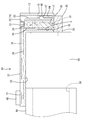
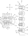
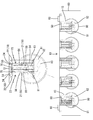
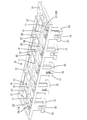
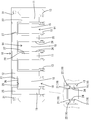
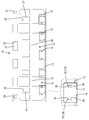
- each holder side connector is a perspective view which shows the state hold
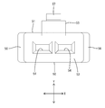
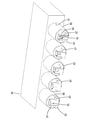
- FIG. 13 It is a top view of a connector holder. It is a bottom view of a connector holder. It is a perspective view of a housing. It is a front view of a housing. It is a top view of a housing. It is a perspective view which shows the state by which each solenoid which provided the apparatus side connector integrally was assembled
- the holder-side connector has a portion protruding from the connector holder at the alignment position. According to this, when an operator pushes in the protrusion part of a holder side connector, a holder side connector can be easily brought to a pushing position.
- the connector holder has a conductive portion support surface that supports a conductive member extending from the connector. According to this, since the connector holder can have both the function as the fitting device described above and the function of supporting the conductive member, the entire structure is simplified compared to the case where each is constituted by separate parts. Can be.
- the connector holder has a conductive portion regulating piece provided to cover the conductive member so as to face the side where the conductive portion supporting surface is located. According to this, the floating of the conductive member from the conductive portion support surface can be restricted by the conductive portion restricting piece, the biting of the conductive member can be prevented, and the apparatus can be made low in height. . Further, when the conductive member is an electric wire, it is not necessary to use a tie band or the like, so that troublesome bundling work of the electric wire can be omitted.
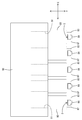
- the connector fitting device of the embodiment exemplifies a connector holder 10 that is mounted on an automatic transmission of an automobile (not shown) as a whole.
- the connector holder 10 holds a plurality of holder-side connectors 50 and supports electric wires 70 extending from the holder-side connectors 50.
- the up and down direction is a direction along the direction of gravity with reference to the state mounted on the automobile.
- the right side when viewed from the upper side of FIG. 3 is the front side.
- the Z direction is assumed to be upward
- the Y direction is assumed to be forward
- the X direction is assumed to be right.
- the automatic transmission has a body 90 (including a case of the automatic transmission).
- a plurality of hydraulic control solenoids 80 are assembled to the body 90.
- the solenoid 80 has a columnar shape (cylindrical shape), is inserted into a valve insertion portion 91 that opens to the front surface of the body 90, and is fixed to the body 90 with a pin (not shown) or the like.
- the solenoid 80 is in a state where it can rotate in the valve insertion portion 91 after being fixed by the pin.
- a plurality of solenoids 80 are arranged in a row in the front surface of the body 90.
- the solenoid 80 is integrally provided with a device-side connector 82 equipped with a mating terminal 81 that is electrically connected to an internal coil (not shown).
- the device-side connector 82 protrudes forward from the front end surface of the solenoid 80 (the end surface orthogonal to the outer peripheral surface of the solenoid 80), and protrudes upward from the connection portion 83.
- a hood portion 84 A gap S is formed between the front end surface of the solenoid 80 and the hood portion 84.
- the hood portion 84 is opened upward, and a tab-shaped mating terminal 81 is disposed so as to protrude upward.
- the front wall of the hood portion 84 is provided with a lock hole 85 penetrating in the front-rear direction.
- the holder side connector 50 has a synthetic resin housing 51 inserted into the hood portion 84 of the device side connector 82. As shown in FIG. 10, the housing 51 has a rectangular block-shaped housing body 52 that is long in the vertical direction, and a doubly-supported beam-like lock arm 53 that is spanned between the upper and lower ends on the front surface side of the housing body 52. ing.
- the housing body 52 is provided with a pair of cavities 54 that extend in the vertical direction and open on both the upper and lower sides. As shown in FIG. 5, a terminal fitting 55 is inserted into each cavity 54 from above.
- the terminal fitting 55 is made of a conductive metal and is connected to the terminal portion of the electric wire 70.
- an electrical signal from a CPU (not shown) is transmitted to the solenoid 80 via the electric wire 70. Is done.
- a pair of engaging portions 56 project from the upper portions of the left and right side surfaces of the housing main body 52.
- the engaging portion 56 has a rib shape extending in the front-rear direction, and can be engaged with a holding portion 19 described later of the connector holder 10.
- the lock arm 53 has a belt-like portion extending in the up-down direction, and a lock projection 57 is provided protruding forward in the middle of the extension direction.
- the housing 51 is inserted into the hood portion 84 of the device-side connector 82, and the lock protrusion 57 is elastically fitted into the lock hole 85, so that the holder-side connector 50 is fitted into the device-side connector 82. Held in a combined state.
- the connector holder 10 is a plate member made of synthetic resin, and is attached to the body 90 substantially horizontally via a screw member 60 as shown in FIG. As shown in FIG. 8, a pair of insertion holes 31 through which the screw member 60 can be inserted are provided at the left and right ends of the rear end of the connector holder 10 so as to penetrate vertically.
- the connector holder 10 attached to the body 90 protrudes forward from the front end of the upper surface of the body 90 and is arranged so that each solenoid 80 faces the device-side connector 82 from above.
- the connector holder 10 is connected to the branch line portions 11 extending in the front-rear direction and arranged side by side on the left and right sides, and the branch line portions 11 at the rear end, It has one shallow groove-shaped trunk line portion 12 that is extended and is connected to each branch line portion 11 at the front end portion, and a rectangular tube-shaped connector insertion portion 13 that protrudes downward.
- a space portion 14 is opened between the branch line portions 11.
- a erection part 15 that extends in the left and right direction and connects adjacent branch line parts 11 is provided.
- the holder side connector 50 is inserted into the connector insertion portion 13 from above.
- the connector insertion portions 13 are arranged so as to cover the device-side connectors 82 of the solenoids 80 from above.
- the lower end 16 of the rear wall of the connector insertion portion 13 is inserted into the gap S between the front end surface of the solenoid 80 and the hood portion 84.
- the front wall lower end portion 17 of the connector insertion portion 13 is provided with a rectangular window portion 18 opened from the lower end.
- the lock hole 85 of the hood portion 84 is disposed inside the window portion 18. For this reason, it is possible to know that the holder-side connector 50 has been properly fitted with the device-side connector 82 by looking from the front the state in which the lock protrusion 57 is fitted in the lock hole 85 of the hood portion 84 (see FIG. 2 and FIG. 4).
- a pair of holding portions 19 are provided on the inner surfaces of both sides of the connector insertion portion 13.
- the holding portion 19 includes a lower stopper portion 21 provided at the lower end portions on both inner surfaces of the connector insertion portion 13 and an upper stopper portion 22 provided on the upper end portions on both inner surfaces of the connector insertion portion 13.
- a movement space 23 is secured between the upper stopper part 22 and the lower stopper part 21 to allow the holder side connector 50 inserted into the connector insertion part 13 to move in the vertical direction.
- the lower stopper portion 21 is configured as a substantially flat stepped surface arranged facing upward. As shown in FIG. 8, the lower stopper portion 21 is located on both sides of the upper stopper portion 22 as viewed from above. They are arranged in pairs. As shown in FIG. 5, a step portion 29 capable of contacting the upper end of the hood portion 84 is provided below the lower stopper portion 21.
- the upper stopper portion 22 is configured as a projecting piece protruding inward from the upper end (open end) of the connector insertion portion 13, and can be bent and deformed inward and outward (left and right) with the upper end of the connector insertion portion 13 as a fulcrum.
- a tapered inclined portion 24 that is inclined downward is provided at the distal end portion of the upper stopper portion 22 in the protruding direction.
- the engaging portion 56 of the housing body 52 slides on the inclined portion 24, and the upper stopper portion 22 is bent and deformed. Thereafter, when the engaging portion 56 passes through the inclined portion 24, the upper stopper portion 22 is elastically restored, and the engaging portion 56 enters the moving space 23 and is disposed.
- the engaging portion 56 is movable in the up and down direction in the moving space 23 and is prevented from coming out upward by contacting the protruding end of the upper stopper portion 22 (see FIG. 5). By coming into contact with the stepped surface, the downward pull-out is restricted (see FIG. 6).
- the holder-side connector 50 is positioned at an alignment position that is aligned with the device-side connector 82.
- the holder-side connector 50 is in the push-in position where it is normally fitted to the device-side connector 82.
- the holder-side connector 50 is also idled in the direction (including the front-rear direction and the left-right direction) intersecting the vertical direction within the gap range with the connector insertion portion 13 with the engaging portion 56 entering the moving space 23. It is in a state to get.
- the branch line part 11 and the trunk line part 12 include a conductive part support surface 25 that constitutes a groove bottom where the electric wire 70 is supported, and the conductive part support surface 25 extending in the length direction of the electric wire 70. It has a rib-shaped partitioning section 26 that partitions both sides.
- the partition part 26 is integrally connected to the installation part 15, and the partition part 26 and the installation part 15 form a rectangular frame shape.
- the branch line part 11 and the trunk line part 12 are rectangular plate-shaped protruding from the upper end of one partition part 26 toward the other partition part 26 among the partition parts 26 on both sides of the conductive part support surface 25.
- a conductive part regulating piece 27 is provided. As shown in FIGS. 2 and 4, the conductive portion regulating piece 27 is disposed so as to cover the electric wire 70 supported by the conductive portion supporting surface 25 from above, and can regulate the lifting of the electric wire 70.
- a plurality of conductive portion regulating pieces 27 are provided at one branch line portion 11 and at a substantially constant interval on the main line portion 12.
- the upper surface of the conductive portion regulating piece 27 is continuous with no difference in level from the upper surfaces of the partition portion 26 and the erection portion 15.
- a slit-like introduction port 28 through which the electric wire 70 can be introduced onto the conductive part support surface 25 is opened.
- a portion of the groove bottom constituting the conductive portion support surface 25 that faces the conductive portion regulating piece 27 is a die cut through which a mold for forming the conductive portion regulating piece 27 passes.
- the holes 33 penetrate vertically.
- the solenoid 80 is inserted into each valve insertion portion 91 of the body 90 in a state where rotation around the axis is permitted.
- the terminal fitting 55 is inserted into the housing 51 of the holder-side connector 50 (see FIGS. 13 to 15). Subsequently, the holder-side connector 50 is inserted into the connector insertion portion 13 of the connector holder 10 from above. After the upper stopper portion 22 interferes with the engaging portion 56 and is bent and deformed, the upper stopper portion 22 is elastically restored by the engagement portion 56 entering the moving space 23, and the holder-side connector 50 is The holder 19 is held so as to be movable in the vertical direction (see FIGS. 5 and 6).
- the electric wires 70 extending from the upper end surface of the housing 51 are arranged along the conductive portion support surface 25 from the corresponding branch line portion 11 to the main line portion 12, and are inserted into the conductive portion regulating piece 27 through the introduction port 28. .
- the conductive portion regulating piece 27 interferes with the electric wire 70 and is bent and deformed, and as the electric wire 70 passes through the introduction port 28, it is elastically restored and covers the upper portion of the electric wire 70.
- each connector insertion portion 13 is placed on the device side connector 82 of each corresponding solenoid 80 from above.
- the holder side connector 50 inserted in each connector insertion part 13 is collectively arrange
- an operation of inserting the holder-side connector 50 into each connector insertion portion 13 may be performed.
- the holder-side connector 50 When the holder-side connector 50 is disposed above the device-side connector 82 by the connector holder 10, the holder-side connector 50 is fitted to the device-side connector 82 due to rotation around the axis of the solenoid 80 or due to dimensional tolerance or dimensional error. It is not always arranged so as to face the position where it can be matched. In this regard, in the case of the present embodiment, the holder-side connector 50 can move within a range in which the engaging portion 56 can displace the moving space 23 at the alignment position, so that the lower end of the housing 51 is the upper end opening edge of the hood portion 84. Is smoothly guided to a state of being drawn into the hood portion 84 while sliding.
- each holder-side connector 50 When the holder-side connector 50 is in the alignment position and the lock protrusion 57 is in contact with the upper end opening edge of the hood portion 84 as described above, the upper end portion of the housing 51 is partially upward from the upper end opening of the connector insertion portion 13. (See FIGS. 1 and 3). From this state, a downward pressing force is applied to the upper end of the protruding portion (upper end portion) of the housing 51 directly or indirectly via the electric wire 70 extending from the upper end of the housing 51. For example, each holder-side connector 50 is individually pushed downward by an operator's finger, or each holder-side connector 50 is collectively pushed downward using a plate-shaped jig or the like.
- the lock projection 57 moves away from the upper end opening edge of the hood portion 84, and the lock projection 57 slides on the inner surface of the front wall of the hood portion 84 with the bending operation of the lock arm 53.
- the lock arm 53 is elastically restored, the lock projection 57 is fitted into the lock hole 85 of the hood portion 84 from the inside, and the holder side connector 50 is moved.
- the device side connector 82 is held in a properly fitted state (see FIG. 4).
- the holder-side connector 50 reaches the pushed-in position, the entire housing 51 is inserted into the connector insertion portion 13, and the upper end of the housing 51 is disposed so as to be retracted below the upper end opening edge of the connector insertion portion 13.
- the connector holder 10 is attached to the body 90 of the automatic transmission, so that each holder-side connector 50 is collectively placed at an alignment position corresponding to the device-side connector 82 of each solenoid 80. Since each holder-side connector 50 is aligned in a state where fitting with the device-side connector 82 can be started, the subsequent fitting operation can be performed smoothly. Further, since each holder-side connector 50 is pressed from the alignment position to reach the push-in position where it is fitted with the device-side connector 82, there is no need to perform complicated fitting work, and there is no need for operator's confusion or wrong fitting. There is also little risk of failure. As a result, the fitting workability of the holder side connector 50 can be improved.
- the upper end of the housing 51 is arranged so as to protrude upward at the alignment position.
- the holder-side connector 50 can reach the pushed position, so that the work is easy and the fitting work is performed. Workability can be further improved.
- the upper end portion of the housing 51 protrudes from the upper end of the connector holder 10, it is easy to identify from the surroundings, and it is possible to prevent the user from forgetting to work.
- the connector holder 10 has both a function as a fitting device and a function of supporting the electric wire 70 extending from each holder-side connector 50, the dedicated device is not required. Furthermore, since the floating of the electric wire 70 can be restricted by the conductive portion restricting piece 27, the entire apparatus can be made low in height, and the electric wire 70 can be fastened with a tie band, or the electric wire 70 can be passed through the tube. There is no need to perform the troublesome work.
- the holding portion is formed of an elastic piece that can be bent and deformed, and the holder-side connector is elastically held by the elastic piece with respect to the connector insertion portion, and is pushed from the alignment position.
- the configuration may be such that the holding state is released and the push-in position is reached.
- the direction in which the holder-side connector is pushed in does not have to be from above, but may be lateral or rearward.
- the device-side connector is not limited to a solenoid, and may be provided in a hydraulic sensor or the like of an automatic transmission.
- a tie band or a tube may be used to bundle each electric wire, and the present invention does not deny the use of a tie band or the like.
- a bus bar may be attached to the holder-side connector as a conductive member other than the terminal fitting. When the bus bar is attached to the holder-side connector, the bus bar is supported on the conductive portion support surface.
Landscapes
- Engineering & Computer Science (AREA)
- Manufacturing & Machinery (AREA)
- Details Of Connecting Devices For Male And Female Coupling (AREA)
- Coupling Device And Connection With Printed Circuit (AREA)
Priority Applications (2)
| Application Number | Priority Date | Filing Date | Title |
|---|---|---|---|
| CN201680044855.1A CN107925198B (zh) | 2015-08-07 | 2016-07-19 | 连接器嵌合装置 |
| US15/750,921 US10205278B2 (en) | 2015-08-07 | 2016-07-19 | Connector connecting device |
Applications Claiming Priority (2)
| Application Number | Priority Date | Filing Date | Title |
|---|---|---|---|
| JP2015-156745 | 2015-08-07 | ||
| JP2015156745A JP6481859B2 (ja) | 2015-08-07 | 2015-08-07 | コネクタ嵌合装置 |
Publications (1)
| Publication Number | Publication Date |
|---|---|
| WO2017026231A1 true WO2017026231A1 (ja) | 2017-02-16 |
Family
ID=57983241
Family Applications (1)
| Application Number | Title | Priority Date | Filing Date |
|---|---|---|---|
| PCT/JP2016/071114 Ceased WO2017026231A1 (ja) | 2015-08-07 | 2016-07-19 | コネクタ嵌合装置 |
Country Status (4)
| Country | Link |
|---|---|
| US (1) | US10205278B2 (cg-RX-API-DMAC7.html) |
| JP (1) | JP6481859B2 (cg-RX-API-DMAC7.html) |
| CN (1) | CN107925198B (cg-RX-API-DMAC7.html) |
| WO (1) | WO2017026231A1 (cg-RX-API-DMAC7.html) |
Families Citing this family (1)
| Publication number | Priority date | Publication date | Assignee | Title |
|---|---|---|---|---|
| JP7122807B2 (ja) | 2017-02-28 | 2022-08-22 | 株式会社吉野工業所 | 造形ヘッド |
Citations (2)
| Publication number | Priority date | Publication date | Assignee | Title |
|---|---|---|---|---|
| JP2014127309A (ja) * | 2012-12-26 | 2014-07-07 | Auto Network Gijutsu Kenkyusho:Kk | 並列部材、コネクタの嵌合方法、及び機器の組み立て方法 |
| JP2014127308A (ja) * | 2012-12-26 | 2014-07-07 | Auto Network Gijutsu Kenkyusho:Kk | 並列部材、コネクタの嵌合方法、及び機器の組み立て方法 |
Family Cites Families (5)
| Publication number | Priority date | Publication date | Assignee | Title |
|---|---|---|---|---|
| JP4239906B2 (ja) * | 2004-06-18 | 2009-03-18 | 住友電装株式会社 | 中継コネクタと電気部品との接続構造 |
| JP4968344B2 (ja) * | 2008-01-28 | 2012-07-04 | パナソニック株式会社 | コネクター保持装置 |
| JP5303378B2 (ja) | 2009-06-26 | 2013-10-02 | 矢崎総業株式会社 | 待ち受けコネクタ |
| JP5275133B2 (ja) * | 2009-05-14 | 2013-08-28 | 矢崎総業株式会社 | コネクタモジュール |
| JP6215880B2 (ja) * | 2014-11-14 | 2017-10-18 | 矢崎総業株式会社 | コネクタの一括接続構造、ガイドフレーム、回路体保持状態ガイドフレーム、及びコネクタの一括接続方法 |
-
2015
- 2015-08-07 JP JP2015156745A patent/JP6481859B2/ja active Active
-
2016
- 2016-07-19 US US15/750,921 patent/US10205278B2/en active Active
- 2016-07-19 CN CN201680044855.1A patent/CN107925198B/zh active Active
- 2016-07-19 WO PCT/JP2016/071114 patent/WO2017026231A1/ja not_active Ceased
Patent Citations (2)
| Publication number | Priority date | Publication date | Assignee | Title |
|---|---|---|---|---|
| JP2014127309A (ja) * | 2012-12-26 | 2014-07-07 | Auto Network Gijutsu Kenkyusho:Kk | 並列部材、コネクタの嵌合方法、及び機器の組み立て方法 |
| JP2014127308A (ja) * | 2012-12-26 | 2014-07-07 | Auto Network Gijutsu Kenkyusho:Kk | 並列部材、コネクタの嵌合方法、及び機器の組み立て方法 |
Also Published As
| Publication number | Publication date |
|---|---|
| JP2017037727A (ja) | 2017-02-16 |
| US10205278B2 (en) | 2019-02-12 |
| US20180241153A1 (en) | 2018-08-23 |
| CN107925198A (zh) | 2018-04-17 |
| CN107925198B (zh) | 2019-08-16 |
| JP6481859B2 (ja) | 2019-03-13 |
Similar Documents
| Publication | Publication Date | Title |
|---|---|---|
| CN104779467B (zh) | 带有端子位置保证的电连接器 | |
| KR101320881B1 (ko) | 단자가이드를 갖는 커넥터 | |
| US10971851B2 (en) | Miniaturized connector with a terminal holding member | |
| JP2008152952A (ja) | 端子挿入装置 | |
| US9722353B2 (en) | Connector with alignment function | |
| JP2006244709A (ja) | コネクタ、コネクタ検査装置およびコネクタ検査方法 | |
| JP6481859B2 (ja) | コネクタ嵌合装置 | |
| CN108352656B (zh) | 连接器装置 | |
| WO2019035331A1 (ja) | コネクタ | |
| KR20180130485A (ko) | 스폿 용접용 전극 하우징 장치 | |
| US20150380850A1 (en) | Connector | |
| US20180287300A1 (en) | Electrical connection device | |
| JP4782230B2 (ja) | 車両用ワイヤハーネス及び車両の配線方法 | |
| US10326232B2 (en) | Connector connecting member enabling holding-side connectors to be connected easily to device-side connectors | |
| JP6730975B2 (ja) | 電気コネクタ及び該電気コネクタ内の接続端子の係止方法 | |
| KR20160147158A (ko) | 커넥터 어셈블리 | |
| JP2017117625A (ja) | コネクタ及び待ち受けコネクタ | |
| JP2008177096A (ja) | コネクタのロック機構 | |
| JP2014127309A (ja) | 並列部材、コネクタの嵌合方法、及び機器の組み立て方法 | |
| KR101246518B1 (ko) | 커넥터 조립체 | |
| JP6528919B1 (ja) | 端子台装置 | |
| WO2015033828A1 (ja) | 部品取り外し治具 | |
| JP4449985B2 (ja) | コネクタ検査装置 | |
| JP2014032857A (ja) | コネクタ | |
| KR101595364B1 (ko) | 커넥터 어셈블리 |
Legal Events
| Date | Code | Title | Description |
|---|---|---|---|
| 121 | Ep: the epo has been informed by wipo that ep was designated in this application |
Ref document number: 16834928 Country of ref document: EP Kind code of ref document: A1 |
|
| WWE | Wipo information: entry into national phase |
Ref document number: 15750921 Country of ref document: US |
|
| NENP | Non-entry into the national phase |
Ref country code: DE |
|
| 122 | Ep: pct application non-entry in european phase |
Ref document number: 16834928 Country of ref document: EP Kind code of ref document: A1 |