WO2017026103A1 - 作業車両 - Google Patents
作業車両 Download PDFInfo
- Publication number
- WO2017026103A1 WO2017026103A1 PCT/JP2016/003520 JP2016003520W WO2017026103A1 WO 2017026103 A1 WO2017026103 A1 WO 2017026103A1 JP 2016003520 W JP2016003520 W JP 2016003520W WO 2017026103 A1 WO2017026103 A1 WO 2017026103A1
- Authority
- WO
- WIPO (PCT)
- Prior art keywords
- dashboard
- fuel tank
- attachment
- support member
- mounting
- Prior art date
Links
- 239000002828 fuel tank Substances 0.000 claims abstract description 138
- 230000002093 peripheral effect Effects 0.000 claims description 31
- 239000007858 starting material Substances 0.000 claims description 14
- 229920001971 elastomer Polymers 0.000 description 41
- 239000005060 rubber Substances 0.000 description 41
- 238000003780 insertion Methods 0.000 description 21
- 230000037431 insertion Effects 0.000 description 21
- 238000005452 bending Methods 0.000 description 12
- 230000007246 mechanism Effects 0.000 description 9
- 239000000446 fuel Substances 0.000 description 6
- 230000005540 biological transmission Effects 0.000 description 5
- 230000008859 change Effects 0.000 description 5
- 125000006850 spacer group Chemical group 0.000 description 5
- 239000000498 cooling water Substances 0.000 description 4
- 239000003921 oil Substances 0.000 description 4
- 230000000149 penetrating effect Effects 0.000 description 4
- XLYOFNOQVPJJNP-UHFFFAOYSA-N water Substances O XLYOFNOQVPJJNP-UHFFFAOYSA-N 0.000 description 4
- 210000000078 claw Anatomy 0.000 description 3
- 239000000470 constituent Substances 0.000 description 3
- 238000002955 isolation Methods 0.000 description 3
- 238000004519 manufacturing process Methods 0.000 description 3
- 238000000034 method Methods 0.000 description 3
- 241000209094 Oryza Species 0.000 description 2
- 235000007164 Oryza sativa Nutrition 0.000 description 2
- 239000003990 capacitor Substances 0.000 description 2
- 230000000694 effects Effects 0.000 description 2
- 238000002347 injection Methods 0.000 description 2
- 239000007924 injection Substances 0.000 description 2
- 239000002184 metal Substances 0.000 description 2
- 230000001105 regulatory effect Effects 0.000 description 2
- 235000009566 rice Nutrition 0.000 description 2
- 230000006641 stabilisation Effects 0.000 description 2
- 238000011105 stabilization Methods 0.000 description 2
- 238000003466 welding Methods 0.000 description 2
- 238000004378 air conditioning Methods 0.000 description 1
- 238000013459 approach Methods 0.000 description 1
- 238000002485 combustion reaction Methods 0.000 description 1
- 230000001276 controlling effect Effects 0.000 description 1
- 238000001816 cooling Methods 0.000 description 1
- 230000008878 coupling Effects 0.000 description 1
- 238000010168 coupling process Methods 0.000 description 1
- 238000005859 coupling reaction Methods 0.000 description 1
- 238000010586 diagram Methods 0.000 description 1
- 230000005484 gravity Effects 0.000 description 1
- 238000003306 harvesting Methods 0.000 description 1
- 239000010720 hydraulic oil Substances 0.000 description 1
- 230000006872 improvement Effects 0.000 description 1
- 238000009434 installation Methods 0.000 description 1
- 238000005304 joining Methods 0.000 description 1
- 239000007788 liquid Substances 0.000 description 1
- 230000009467 reduction Effects 0.000 description 1
- 239000003507 refrigerant Substances 0.000 description 1
- 238000009331 sowing Methods 0.000 description 1
- 239000000126 substance Substances 0.000 description 1
- 229920003002 synthetic resin Polymers 0.000 description 1
- 239000000057 synthetic resin Substances 0.000 description 1
Images


Classifications
-
- B—PERFORMING OPERATIONS; TRANSPORTING
- B60—VEHICLES IN GENERAL
- B60K—ARRANGEMENT OR MOUNTING OF PROPULSION UNITS OR OF TRANSMISSIONS IN VEHICLES; ARRANGEMENT OR MOUNTING OF PLURAL DIVERSE PRIME-MOVERS IN VEHICLES; AUXILIARY DRIVES FOR VEHICLES; INSTRUMENTATION OR DASHBOARDS FOR VEHICLES; ARRANGEMENTS IN CONNECTION WITH COOLING, AIR INTAKE, GAS EXHAUST OR FUEL SUPPLY OF PROPULSION UNITS IN VEHICLES
- B60K15/00—Arrangement in connection with fuel supply of combustion engines or other fuel consuming energy converters, e.g. fuel cells; Mounting or construction of fuel tanks
- B60K15/03—Fuel tanks
- B60K15/063—Arrangement of tanks
-
- B—PERFORMING OPERATIONS; TRANSPORTING
- B60—VEHICLES IN GENERAL
- B60K—ARRANGEMENT OR MOUNTING OF PROPULSION UNITS OR OF TRANSMISSIONS IN VEHICLES; ARRANGEMENT OR MOUNTING OF PLURAL DIVERSE PRIME-MOVERS IN VEHICLES; AUXILIARY DRIVES FOR VEHICLES; INSTRUMENTATION OR DASHBOARDS FOR VEHICLES; ARRANGEMENTS IN CONNECTION WITH COOLING, AIR INTAKE, GAS EXHAUST OR FUEL SUPPLY OF PROPULSION UNITS IN VEHICLES
- B60K15/00—Arrangement in connection with fuel supply of combustion engines or other fuel consuming energy converters, e.g. fuel cells; Mounting or construction of fuel tanks
- B60K15/03—Fuel tanks
- B60K15/073—Tank construction specially adapted to the vehicle
-
- B—PERFORMING OPERATIONS; TRANSPORTING
- B60—VEHICLES IN GENERAL
- B60K—ARRANGEMENT OR MOUNTING OF PROPULSION UNITS OR OF TRANSMISSIONS IN VEHICLES; ARRANGEMENT OR MOUNTING OF PLURAL DIVERSE PRIME-MOVERS IN VEHICLES; AUXILIARY DRIVES FOR VEHICLES; INSTRUMENTATION OR DASHBOARDS FOR VEHICLES; ARRANGEMENTS IN CONNECTION WITH COOLING, AIR INTAKE, GAS EXHAUST OR FUEL SUPPLY OF PROPULSION UNITS IN VEHICLES
- B60K35/00—Instruments specially adapted for vehicles; Arrangement of instruments in or on vehicles
-
- B—PERFORMING OPERATIONS; TRANSPORTING
- B60—VEHICLES IN GENERAL
- B60K—ARRANGEMENT OR MOUNTING OF PROPULSION UNITS OR OF TRANSMISSIONS IN VEHICLES; ARRANGEMENT OR MOUNTING OF PLURAL DIVERSE PRIME-MOVERS IN VEHICLES; AUXILIARY DRIVES FOR VEHICLES; INSTRUMENTATION OR DASHBOARDS FOR VEHICLES; ARRANGEMENTS IN CONNECTION WITH COOLING, AIR INTAKE, GAS EXHAUST OR FUEL SUPPLY OF PROPULSION UNITS IN VEHICLES
- B60K37/00—Dashboards
- B60K37/10—Arrangements for attaching the dashboard to the vehicle
-
- B—PERFORMING OPERATIONS; TRANSPORTING
- B62—LAND VEHICLES FOR TRAVELLING OTHERWISE THAN ON RAILS
- B62D—MOTOR VEHICLES; TRAILERS
- B62D25/00—Superstructure or monocoque structure sub-units; Parts or details thereof not otherwise provided for
- B62D25/08—Front or rear portions
- B62D25/14—Dashboards as superstructure sub-units
-
- B—PERFORMING OPERATIONS; TRANSPORTING
- B62—LAND VEHICLES FOR TRAVELLING OTHERWISE THAN ON RAILS
- B62D—MOTOR VEHICLES; TRAILERS
- B62D33/00—Superstructures for load-carrying vehicles
- B62D33/06—Drivers' cabs
- B62D33/0617—Drivers' cabs for tractors or off-the-road vehicles
-
- B—PERFORMING OPERATIONS; TRANSPORTING
- B62—LAND VEHICLES FOR TRAVELLING OTHERWISE THAN ON RAILS
- B62D—MOTOR VEHICLES; TRAILERS
- B62D49/00—Tractors
-
- B—PERFORMING OPERATIONS; TRANSPORTING
- B60—VEHICLES IN GENERAL
- B60K—ARRANGEMENT OR MOUNTING OF PROPULSION UNITS OR OF TRANSMISSIONS IN VEHICLES; ARRANGEMENT OR MOUNTING OF PLURAL DIVERSE PRIME-MOVERS IN VEHICLES; AUXILIARY DRIVES FOR VEHICLES; INSTRUMENTATION OR DASHBOARDS FOR VEHICLES; ARRANGEMENTS IN CONNECTION WITH COOLING, AIR INTAKE, GAS EXHAUST OR FUEL SUPPLY OF PROPULSION UNITS IN VEHICLES
- B60K15/00—Arrangement in connection with fuel supply of combustion engines or other fuel consuming energy converters, e.g. fuel cells; Mounting or construction of fuel tanks
- B60K15/03—Fuel tanks
- B60K15/063—Arrangement of tanks
- B60K2015/0637—Arrangement of tanks the fuel tank is arranged in the front of the vehicle
-
- B—PERFORMING OPERATIONS; TRANSPORTING
- B60—VEHICLES IN GENERAL
- B60K—ARRANGEMENT OR MOUNTING OF PROPULSION UNITS OR OF TRANSMISSIONS IN VEHICLES; ARRANGEMENT OR MOUNTING OF PLURAL DIVERSE PRIME-MOVERS IN VEHICLES; AUXILIARY DRIVES FOR VEHICLES; INSTRUMENTATION OR DASHBOARDS FOR VEHICLES; ARRANGEMENTS IN CONNECTION WITH COOLING, AIR INTAKE, GAS EXHAUST OR FUEL SUPPLY OF PROPULSION UNITS IN VEHICLES
- B60K2360/00—Indexing scheme associated with groups B60K35/00 or B60K37/00 relating to details of instruments or dashboards
- B60K2360/60—Structural details of dashboards or instruments
- B60K2360/61—Specially adapted for utility vehicles
-
- B—PERFORMING OPERATIONS; TRANSPORTING
- B62—LAND VEHICLES FOR TRAVELLING OTHERWISE THAN ON RAILS
- B62D—MOTOR VEHICLES; TRAILERS
- B62D25/00—Superstructure or monocoque structure sub-units; Parts or details thereof not otherwise provided for
- B62D25/08—Front or rear portions
- B62D25/14—Dashboards as superstructure sub-units
- B62D25/145—Dashboards as superstructure sub-units having a crossbeam incorporated therein
Definitions
- the present invention relates to a work vehicle having a dashboard.
- Patent Document 1 discloses an automobile including a dashboard arranged to be displaceable, although it relates to a shared bus, not a work vehicle.
- the steering column and the dashboard are not movable relative to each other, but rather form one constituent unit that can be moved up and down and swivel, and the constituent unit is connected via an appropriate slider guide. It can be moved and adjusted, and can be locked at any position.
- a stabilization device is arranged belonging to a dashboard.
- the slider guides provided in the stabilization device are provided on guide rails which are located at a considerable distance from one another, and this slider guide is combined with a gear / rack coupling.
- Patent Document 1 the steering column and the dashboard are not movable relative to each other but are formed as one constituent unit. For this reason, the configuration of Patent Document 1 is not necessarily suitable when manufacturing work vehicles having a plurality of specifications with different dashboard positions. Further, in Patent Document 1, since a device such as a slider guide is required to adjust the structural unit including the steering column and the dashboard, the adjustment structure is complicated, which is disadvantageous in terms of cost. .
- the present invention has been made in view of the above circumstances, and an object of the present invention is to provide a work vehicle that can easily realize another specification with a simple configuration and a different dashboard position.
- a work vehicle having the following configuration. That is, the work vehicle includes a fuel tank, a fuel tank cover, a support member, and a dashboard.
- the fuel tank is provided at a rear portion in the bonnet in the front-rear direction of the vehicle body.
- the fuel tank cover covers a rear portion of the fuel tank.
- the support member is attached to the fuel tank cover.
- the dashboard is supported by the support member.
- the fuel tank cover includes an attachment portion for attaching the support member.
- the dashboard can be directly attached to the attachment portion.
- the dashboard can be arranged at different positions depending on the presence or absence of the support member.
- the dashboard and fuel tank cover, etc. can be diverted to work vehicles with different specifications that have different dashboard layout positions, so there is no need to change the design of the dashboard and fuel tank cover, etc. Time and cost can be reduced.
- the dashboard can be attached to different positions with a simple configuration that only switches whether or not the support member is attached.
- the work vehicle has the following configuration. That is, the dashboard includes a fixing portion formed so as to be directly attached to the attachment portion of the support member in the fuel tank cover.
- the support member supports the dashboard via the fixing portion of the dashboard.
- the fixed portion of the dashboard attached to the support member can be used as a fixing means when the dashboard is directly attached to the fuel tank cover without the support member. Therefore, the dashboard can be mounted in different positions with a simple and compact configuration.
- the work vehicle has the following configuration. That is, the support member is composed of a plate member, and is attached to each of the left and right sides of the upper portion of the fuel tank cover.
- the dashboard can be attached to a plurality of positions in the vertical direction depending on the presence or absence of the support member.
- the support member can be easily formed and the dashboard can be stably supported at a high position.
- the work vehicle includes a cover member that is connected to a lower end portion of the dashboard and covers a space below the space between the dashboard and the fuel tank cover.
- cover member below the dashboard mounted relatively high by the support member.
- cover member as a member different from the dashboard, in another specification in which the dashboard is mounted at a low position, the cover member can be omitted and a compact configuration can be realized.
- the work vehicle has the following configuration. That is, the dashboard includes an operation panel unit and an outer peripheral board unit. The outer peripheral board portion is fixed to the operation panel portion.
- the fuel tank cover includes an operation panel portion attachment portion for attaching the operation panel portion separately from the attachment portion. The operation panel portion is attached to the operation panel portion attachment portion of the fuel tank cover via an attachment member.
- the attachment member is preferably formed in a plate shape and has a plurality of attachment holes that can be attached to the operation panel attachment portion.
- the attachment member includes a member having a distance between a plurality of attachment holes that is a half of an amount at which the attachment position of the dashboard changes depending on the presence or absence of the support member. Is preferably included.
- the attachment member preferably includes a member that supports an engine starter switch for starting an engine included in the vehicle body.
- positioning of the vibration proof rubber with respect to a bracket The perspective view which shows the mode of a support member and a bracket in the tractor of a specification with a low position of a steering column.
- the perspective view which shows a mode that a support member is attached to a fuel tank cover.
- the perspective view which shows a mode that a dashboard is attached to the fuel tank cover via the supporting member.
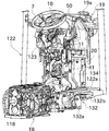
- FIG. 1 is a left side view showing the overall configuration of the tractor 100.
- “left”, “right”, and the like mean left and right in the direction in which the tractor 100 moves forward.
- a tractor 100 as a work vehicle for agricultural work shown in FIG. 1 is configured to be able to perform various types of work by attaching various work devices such as plows and loaders as necessary.
- the tractor 100 includes a body (vehicle body) 2, a pair of left and right front wheels 3, and a pair of left and right rear wheels 4.
- the front wheel 3 supports the front part of the body 2
- the rear wheel 4 supports the rear part of the body 2.
- a bonnet 9 is disposed at the front of the body 2 of the tractor 100, and the bonnet 9 is configured to be openable and closable so that the inside can be exposed.
- the bonnet 9 is formed in a streamline shape, and its front part is formed so as to become narrower in both the vertical direction and the horizontal direction as it approaches the front. With this shape, a reduction in air resistance during travel and an improvement in design are realized.
- a fan shroud 110, a radiator 111, a condenser 112, an engine control unit (ECU) 113, an air cleaner 114, and a battery 115 are disposed in front of the engine 5.
- the fan shroud 110, the condenser 112, the engine control unit (ECU) 113, the air cleaner 114, and the battery 115 are arranged in the above order from the rear to the front on the upper side of a mounting plate (not shown) fixed to the engine frame 16. These are housed in the bonnet 9.
- the fuel tank 19 is disposed at the top of the engine 5.
- the fuel tank 19 has an oil filling port 19a in the upper part, from which oil is poured.
- the oil filling port 19 a is disposed so as to protrude from a hole provided in the upper part of the bonnet 9, so that the operator can perform the oiling work without depending on the open / closed state of the bonnet 9. It is possible.
- the front portion 19 b of the fuel tank 19 is disposed above the engine 5 in the internal space of the bonnet 9.
- the rear portion 19 c of the fuel tank 19 is covered with a fuel tank cover 30 and is disposed inside a dashboard 50 provided in the cabin 6.
- the engine 5 is configured as a common rail type diesel engine having a plurality of cylinders. Specifically, the engine 5 includes an unillustrated common rail that stores the fuel supplied from the fuel tank 19 at a high pressure. The fuel supplied from the common rail is injected into a combustion chamber in the cylinder by an injector (not shown) arranged for each cylinder.
- the fan shroud 110 is configured to cover the outer periphery of the cooling fan driven by the engine 5, and is disposed in front of the engine 5. On the upper right side of the fan shroud 110, a notch (not shown) for passing a member such as the intake pipe 116 of the engine 5 is provided.
- the fan shroud 110 is configured to divide the inner section of the bonnet 9 in the front-rear direction. Therefore, heat from the engine 5 can be shielded against devices (such as the radiator 111 and the condenser 112) arranged in front of the fan shroud 110.
- the radiator 111 is a device that cools the cooling water in the water jacket of the engine 5, and is attached to the front side of the radiator 111. Between the radiator 111 and a not-shown water jacket formed in the engine 5, a not-shown circulation path for circulating the cooling water is formed. The cooling water in the water jacket that has become hot due to the heat generated by the engine 5 is sent to the radiator 111. The cooling water is cooled by outside air taken in from a front grill (not shown) when passing through the radiator 111, and then returns to the water jacket again to cool the engine 5.
- the condenser 112 is configured as a heat exchanger, and is configured with a tube through which a high-pressure liquid refrigerant used for an air conditioner that performs air conditioning in the cabin 6 passes, and a corrugated type or a plate type around the tube. And fins as main components.
- the capacitor 112 is supported by a capacitor frame (not shown) and is attached to the front side of the radiator 111.
- the ECU 113 is configured as a small computer.
- the ECU 113 controls the operation of the engine 5 by issuing a control command for controlling the fuel injection amount, the fuel injection timing, and the like based on information from various sensors attached to the engine 5.
- the air cleaner 114 has a configuration in which an air cleaner element for removing foreign substances in the air is housed inside.
- the air cleaner 114 is connected to the engine 5 by an intake pipe 116 and constitutes a part of the intake structure of the engine 5.
- the battery 115 supplies electric power to various electrical components included in the tractor 100 (for example, a cell motor included in the engine 5, a headlight of the tractor 100, an ECU 113, and the like).
- a cabin 6 for installation by an operator is installed at the rear part of the machine body 2. Inside the cabin 6 are provided a steering handle 7 for the operator to steer, a driver seat 8 for the operator to sit on, and various operation devices for performing various operations.
- an operation panel 10 disposed in front of the steering handle 7 can be cited.
- the operation panel 10 is fixed to a dashboard 50 disposed in front of the steering handle 7.
- instruments such as a speedometer, a fuel meter, and a distance meter (not shown) that indicate information necessary for traveling the tractor 100 are disposed.
- the aircraft frame constituting the skeleton of the aircraft 2 includes an engine frame 16 and a mission case 18.
- a front axle case 17 is attached to the lower side of the engine frame 16.
- a front wheel 3 is attached to the front axle case 17 via a front axle 130.
- the rear wheel 4 is attached to the transmission case 18 via the rear axle 14.
- Upper portions of the left and right rear wheels 4 are covered with left and right rear fenders 121.
- the engine frame 16 and the mission case 18 are each formed in an elongated shape, and both are arranged such that the longitudinal direction thereof is the front-rear direction.
- the mission case 18 is fixed to the rear end of the engine frame 16 via an appropriate fixing member.
- the engine frame 16 is supported by the front wheel 3 via the front axle case 17 and the front axle 130, and the transmission case 18 is supported by the rear wheel 4 via the rear axle 14.
- the front wheel 3 and the rear wheel 4 support the body frame composed of the engine frame 16 and the transmission case 18.
- This transmission case 18 decelerates the power from the engine 5 and transmits it to the front axle case 17 and the rear axle 14.
- the speed ratio in the transmission case 18 can be changed and the traveling speed of the tractor 100 can be adjusted.
- the PTO shaft 118 is disposed so as to protrude from the rear end of the mission case 18, and the driving force of the engine 5 is transmitted to the PTO shaft 118.
- the tractor 100 is configured such that the above-described working device can be attached to the rear end thereof.
- the PTO shaft 118 can drive the working device via a universal joint (not shown).
- the tractor 100 configured as described above can perform various operations such as tilling, sowing, and harvesting while traveling in the rice field.
- FIG. 2 is a perspective view showing the configuration of the tractor 100.
- the dashboard 50 of the present embodiment is attached to the rear center of the hood 9 and in the center of the front side inside the cabin 6.
- the dashboard 50 is attached to cover the fuel tank cover 30 that covers the rear portion 19c of the fuel tank 19 (details will be described later).
- a cover that covers the steering column 11 is installed.
- a steering handle 7 is disposed above the steering column cover 123 and obliquely above and behind the dashboard 50.
- the rear part of the dashboard 50 is formed in a shape surrounding the front side of the steering column cover 123 disposed at the center of the left and right.
- the steering column cover 123 is arranged so that the front part thereof is partially embedded in the rear part of the dashboard 50.
- the cabin 6 includes a frame-like cabin frame 122.
- the cabin frame 122 is fixed to the mission case 18 included in the tractor 100.
- the steering column 11 is supported and fixed by a cabin frame 122.
- the cabin frame 122 is fixed to the left and right side surfaces of the mission case 18 via a pair of left and right frame fixing members 132 (however, in FIG. Only member 132 is shown).
- the frame fixing member 132 is formed in a substantially L shape, and includes a plate-like mission case attachment portion 132a and a plate-like frame attachment portion 132b.
- the mission case mounting portion 132a is arranged with its thickness direction facing the left-right direction of the body, and is attached to the side surface of the mission case 18 via bolts or the like.
- the frame attachment portion 132b is disposed with its thickness direction directed in the vertical direction, and is attached to the bottom surface of the bottom plate member 122a so as to support the bottom plate member 122a constituting the cabin frame 122.
- the cabin frame 122 is fixed to the mission case 18 and supported by the rear wheel 4 via the mission case 18.
- the steering column 11 is fixed to the bracket 20 shown in FIG. 5 (in order to show the steering column 11 in an easy-to-understand manner, the steering column cover 123 is transparently shown by a chain line in FIG. 5).
- a frame plate member 134 is fixed to the cabin frame 122 by bolts or the like, and the bracket 20 is fixed to the frame plate member 134 via a support member 41.
- the steering column 11 is supported and fixed to the cabin frame 122 via the support member 41 and the like.
- the dashboard 50 of the present embodiment can be applied to tractors having a plurality of specifications different from each other by switching the presence or absence of a dashboard support member 40 described later.
- the steering column 11 and the steering column cover 123 can also be applied to tractors having a plurality of specifications different from each other by appropriately changing the mounting positions thereof.
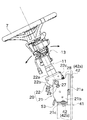
- FIG. 7 is a left side view showing a configuration around the steering column 11 and the bracket 20.
- FIG. 8 is a perspective view showing a configuration around the steering column 11 and the bracket 20. 7 and 8 show a state in which the dashboard 50 is removed.
- an elongated cylindrical steering column 11 is arranged in the dashboard 50.
- the steering column 11 is disposed below the steering handle 7 so as to coincide with the rotation axis of the steering handle 7.
- a lower end portion of the steering column 11 is supported by the bracket 20.
- the steering column 11 is formed in a hollow shape, and a rod-shaped steering shaft (not shown) is disposed inside the steering column 11.
- a steering handle 7 is attached to the upper part of the steering shaft.
- a lower portion of the steering shaft is inserted into the steering column 11 and is supported rotatably with respect to the steering column 11.
- a reverser lever 12 for operating a not-shown forward / reverse switching mechanism provided in the tractor 100 is attached to the upper portion of the steering column 11.
- the steering column 11 is provided with a known telescopic device 13 for adjusting the position of the steering handle 7 in the longitudinal direction of the steering column 11.
- the steering handle 7 has a round handle shape, and can be rotated in both the left and right directions.
- the rotation of the steering handle 7 is input to a steering valve unit provided in a power steering device (not shown) via the steering shaft.
- the steering valve unit switches the supply of hydraulic oil to the cylinder of the power steering device.
- the cylinder is driven to change the direction of the front wheel 3 according to the direction and angle in which the steering handle 7 is rotated, and the traveling direction of the tractor 100 can be changed.
- the reverser lever 12 is disposed on the upper left side of the steering column 11.
- the reverser lever 12 is mounted so as to protrude to the left from the steering column 11, and is configured to be rotatable about an axis directed substantially in the vertical direction.
- the tractor 100 includes a reverser switch (not shown) for detecting the operation of the reverser lever 12. With this configuration, when the operator operates the reverser lever 12 forward or backward, the forward / backward switching mechanism (not shown) provided in the tractor 100 is controlled, and the traveling direction of the tractor 100 can be switched forward or backward. Yes.
- the bracket 20 supports the steering column 11 with respect to a support member 41 fixed to the engine frame 16 of the tractor 100. As shown in FIGS. 7 and 8, the bracket 20 includes a base member 21 and a movable member 22.
- the base member 21 is attached to the support member 41 via a plurality of (four in this embodiment) vibration-proof rubbers 42.
- the movable member 22 is attached to the upper part of the base member 21 via a shaft member 26 arranged in a pair on the left and right.
- the movable member 22 is supported so as to be rotatable about the axis of the shaft member 26 (the rotation shaft 27 arranged in the horizontal direction).
- the rotating shaft 27 corresponds to the tilt axis of the tilt mechanism provided in the bracket 20.
- a lower end portion of the steering column 11 is fixed to the upper portion of the movable member 22.
- FIG. 9 is a left side view of the bracket 20.
- FIG. 10 is a perspective view of the bracket 20.
- the base member 21 included in the bracket 20 is configured as a plate-like member that is bent at a plurality of locations so as to have a gate shape when viewed from the front.
- the base member 21 is integrally provided with a front attachment portion 21a, a pair of left and right shaft support portions 21b, and a pair of left and right lower attachment portions 21c.
- the front mounting portion 21a is formed in a plate shape whose thickness is directed in the front-rear direction.
- the upper portion of the front attachment portion 21a is attached to the support member 41 via a pair of left and right vibration isolation rubbers 42.
- Each of the pair of shaft support portions 21b is formed in a plate shape whose thickness is directed in the left-right direction. Each shaft support portion 21b extends rearward from both left and right end portions of the front mounting portion 21a and is then arranged to extend downward. The shaft support portion 21b is connected to the front mounting portion 21a so as to be vertical in a plan view. The pair of shaft support portions 21b are arranged in parallel to each other, and an appropriate space for arranging the movable member 22 is formed between them. A shaft member 26 for supporting the movable member 22 is attached to each of the shaft support portions 21b.
- Each of the pair of lower mounting portions 21c is formed in a plate shape whose thickness is directed in the vertical direction.
- Each lower attachment portion 21c is disposed so as to protrude from the lower end of the pair of shaft support portions 21b to the left and right sides.
- the lower attachment portion 21c is connected to the shaft support portion 21b so as to be vertical in a front view.
- the left and right pair of lower attachment portions 21c are attached to the support member 41 via vibration-proof rubbers 42, respectively.
- the movable member 22 is configured as a plate-like member in which a plurality of portions are bent, like the base member 21.
- the base member 21 is integrally provided with a column mounting portion 22a, a pair of left and right arm portions 22b, and a spring stopper 22c.
- the column attachment portion 22 a is formed in a plate shape whose thickness is perpendicular to the rotation shaft 27 of the movable member 22.
- the column mounting portion 22a is formed in a rectangular shape, and the lower end portion of the steering column 11 is fixed to the center position by an appropriate method.
- Each of the pair of arm portions 22b is formed in a plate shape whose thickness is directed in the left-right direction.
- Each arm part 22b is arrange
- the pair of arm portions 22b are arranged in parallel with each other, and the steering valve unit (not shown) is arranged between them.
- Each arm portion 22b is rotatably supported with respect to the shaft support portion 21b of the base member 21 via the shaft member 26.
- a stopper member 29 is attached to one arm portion 22b (in this embodiment, the right arm portion 22b).
- the stopper member is configured to pass through an arc-shaped elongated hole 23 formed in a penetrating manner in the shaft support portion 21b of the base member 21 and protrude to the left and right outer sides (right side).
- the stopper member 29 and the long hole 23 the angular stroke in which the movable member 22 rotates is limited to a predetermined range.
- the spring stopper 22c is formed in a plate shape arranged in a direction perpendicular to both the column attachment portion 22a and the arm portion 22b.
- the spring stopper 22c is disposed so as to extend downward from the front end of the column attachment portion 22a.
- the angle of the movable member 22 with respect to the base member 21 (and thus the angle of the steering column 11 and the steering handle 7) is set to a desired angle on the left and right sides (left side in the present embodiment) of the bracket 20.
- a lock mechanism 49 is attached for holding.
- the lock mechanism 49 includes a first lock member 51, a second lock member 52, and a lock release lever 53.
- the first lock member 51 is formed in an elongated plate shape, and is fixed to the inner surface of the arm portion 22b on one side of the movable member 22 (on the left side in the present embodiment). Accordingly, the first lock member 51 rotates integrally with the movable member 22 around the rotation shaft 27.
- An arcuate gear 54 is formed at the lower end of the first lock member 51.
- the second lock member 52 is formed in an elongated plate shape, and is disposed in the vicinity of the inner surface of the shaft support portion 21b on the left and right sides (the left side in the present embodiment) of the base member 21.
- One end (front end) of the second lock member 52 is rotatably supported via a support shaft 56 attached to the shaft support portion 21b.
- a square cam hole 58 that accommodates the cam plate 57 connected to the unlocking lever 53 is formed.
- gear teeth 55 that can mesh with the arcuate gear 54 of the first lock member 51 are formed at the upper edge of the middle portion in the longitudinal direction of the second lock member 52.
- a round bar-shaped regulating shaft 59 is fixed to the second lock member 52, and one end of a coil spring-like spring 68 is attached to the regulating shaft 59.
- the spring 68 is configured as a tension spring, and exerts a spring force in a direction in which the second lock member 52 is brought close to the first lock member 51 (a direction in which the gear teeth 55 and the gear 54 are meshed, specifically upward).
- the restriction shaft 59 protrudes so as to pass through a long hole 67 formed in a penetrating manner in the left shaft support portion 21 b, and the movement stroke of the second lock member 52 is caused by the restriction shaft 59 and the long hole 67. Is limited to a predetermined range.
- the unlocking lever 53 is rotatably attached to the left shaft support portion 21b provided in the base member 21.
- the unlocking lever 53 is connected to the triangular cam plate 57 that is rotatably supported inside the left shaft support portion 21b. Therefore, the cam plate 57 can be rotated by the operator pulling up the unlock lever 53.
- a torsion coil spring-like return spring 69 is attached to the cam plate 57, and this return spring 69 applies a spring force in a direction against the operation of pulling up the lock release lever 53.
- a pair of left and right tension springs (elastic members) 28 are provided between the front mounting portion 21 a of the base member 21 and the spring stopper 22 c of the movable member 22.
- the tension spring 28 is movable in the direction in which the movable member 22 is rotated in the clockwise direction in FIG. 7 (in other words, in the direction in which the movable member 22 resists gravity and falls in the counterclockwise direction in FIG. 7).
- a force is applied to the member 22.
- FIG. 11 is a perspective view showing the arrangement of the anti-vibration rubber 42 with respect to the bracket 20.
- each anti-vibration rubber 42 is provided between the support member 41 and the base member 21 of the bracket 20.
- each anti-vibration rubber 42 has a configuration in which a substantially cylindrical rubber body is disposed around the bolt shaft.
- Four circular holes are formed in the base member 21, and ring-shaped grooves formed on the outer peripheral surface of the rubber body are fixed to the respective circular holes.
- the bolt 20 is bolted to the support member 41, so that the bracket 20 can be supported by the support member 41 in a vibration-proof manner.
- Two of the four anti-vibration rubbers 42 are attached to the front-side attachment portion 21a included in the base member 21 with their bolt shafts facing in the front-rear direction. The remaining two are attached to the left and right lower attachment portions 21c with their bolt shafts directed vertically. Since the lower attachment portion 21c is disposed at a position lower than the front attachment portion 21a, two of the four anti-vibration rubbers 42 are disposed relatively high as shown in FIG. Is placed low.
- the upper two of the four anti-vibration rubbers 42 are provided at positions higher than the rotation shaft 27 of the movable member 22 in the bracket 20, and the lower two are at positions lower than the rotation shaft 27. Is provided.
- the height difference (the height difference between the center points of the rubber bodies) L1 of the anti-vibration rubber 42 provided at two heights in this way is larger than the diameter D1 of the bottom surface of the steering column 11. (L1> D1).
- FIG. 11 which is a perspective view of the bracket 20 as viewed from the front
- the two upper vibration-proof rubbers 42 are arranged at intervals in the left-right direction.
- L2 is greater than the diameter D1 of the bottom surface of the steering column 11 (L2> D1).
- the lower two anti-vibration rubbers 42 are also spaced apart in the left-right direction, and the distance in the left-right direction (the distance between the center points of the rubber bodies) L3 is the diameter D1 of the bottom surface of the steering column 11. It is larger (L3> D1). In this way, the bracket 20 can be further stabilized against vibration by disposing the anti-vibration rubber 42 in the left-right direction as well.
- the upper two anti-vibration rubbers 42 and the lower two anti-vibration rubbers 42 are arranged at different positions in the height direction as described above, and also differ in the front-rear direction. Placed in position. Further, the upper two anti-vibration rubbers 42 and the lower two anti-vibration rubbers 42 have the same configuration, but are arranged such that the directions of the bolt shafts are different from each other. Therefore, the bracket 20 can be more effectively prevented from vibration.
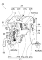
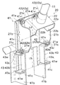
- FIG. 12 is a perspective view showing a state of the support member 41 and the bracket 20 in a tractor having a specification with a low steering column 11.
- FIG. 13 is a perspective view showing the state of the support member 41 and the bracket 20 in a tractor with a high specification of the steering column 11.
- the shaft member 26, the lock mechanism 49, and the like are not shown for easy understanding of the fixing structure between the support member 41 and the bracket 20.
- the support member 41 to which the bracket 20 is fixed is configured as a plate-like member that is bent at a plurality of locations so as to have a gate shape when viewed from the front.
- the support member 41 is integrally provided with a front surface portion 41a, a pair of left and right side portions 41b, and a pair of left and right bent portions 41c.
- the front part 41a is formed in a plate shape whose thickness is directed in the front-rear direction.
- a plurality of mounting holes 41v for mounting a pair of left and right vibration isolating rubbers 42a are formed in the front surface portion 41a.
- the position of the mounting hole 41v corresponds to the circular hole 21v formed in the front mounting portion 21a of the base member 21.
- the mounting holes 41v are arranged in two pairs on the left and right sides of the front surface portion 41a.
- the front portion 41a is formed with an upper pair of left and right mounting holes 41v and a lower pair of left and right mounting holes 41v.
- the four mounting holes 41v and 41w have the same shape.
- Each pair (set) of mounting holes 41v is arranged to be different from the other pair (set) of mounting holes 41v in the left-right direction and the front-rear direction, and the vertical positions are different.
- the upper set of mounting holes 41v and the lower set of mounting holes 41v are arranged so that their heights are different by L4.
- the upper set of attachment holes 41v is formed in the vicinity of the upper end of the support member 41.
- Each of the pair of side surface parts 41b is formed in a plate shape whose thickness is directed in the left-right direction.
- Each side surface portion 41b extends rearward from both left and right end portions of the front surface portion 41a, extends downward, and is further extended rearward.
- the side surface portion 41b is connected to the front surface portion 41a so as to be vertical in a plan view.
- the pair of side surface parts 41b are arranged in parallel to each other, and an appropriate space for arranging the front side attaching part 21a of the bracket 20 is formed between them.
- Each of the pair of bent portions 41c is formed in a plate shape whose thickness is directed in the vertical direction.
- Each bending part 41c is arrange
- the bent portion 41c is connected to the side surface portion 41b so as to be vertical in a front view.
- Each bent portion 41c is formed with an attachment hole 41w for attaching the bolt shaft of the anti-vibration rubber 42b.
- the rubber body of the anti-vibration rubber 42b is attached to each of the circular holes 21w in the pair of left and right lower mounting portions 21c of the bracket 20.
- the bolt shaft of the anti-vibration rubber 42b is attached to the attachment hole 41w formed in the bent portion 41c of the support member 41 by bolting.
- the rubber body of the anti-vibration rubber 42 a is attached to the pair of left and right circular holes 21 v in the front mounting portion 21 a of the bracket 20, and the bolt shaft of the anti-vibration rubber 42 a is formed on the front surface portion 41 a of the support member 41.
- the lower attachment holes 41v are attached by bolting.
- spacers (mounting members) 43 are fixed to a pair of left and right bent portions 41c of the support member 41 as shown in FIG. To do.
- the spacer 43 is configured by appropriately bending a metal plate-like member, and includes a base portion (fixed portion) 43a, an intermediate portion (connecting portion) 43b, and a bent portion (parallel portion) 43c. ing.
- the base portion 43a is formed in a plate shape whose thickness direction is directed in the vertical direction.
- the intermediate portion 43b is formed in a plate shape whose thickness direction is directed in the left-right direction, and extends upward from an end on the inner side in the left-right direction of the base portion 43a.
- the bent portion 43c is formed in a plate shape whose thickness is directed in the vertical direction. Each bending part 43c is arrange
- An attachment hole 43w for attaching the bracket 20 via the anti-vibration rubber 42b is formed in the bent portion 43c.
- the base portion 43a and the bent portion 43c are connected to the intermediate portion 43b so as to be vertical in a front view.
- the base portion 43a of the spacer 43 configured as described above is fixed to the upper surface of the pair of left and right bent portions 41c by, for example, a method such as welding (in the specification of FIG. 13, the mounting hole 41w is substantially Not used). Thereafter, the rubber body of the anti-vibration rubber 42b is attached to each of the circular holes 21w in the pair of left and right lower mounting portions 21c of the bracket 20, and the bolt shaft of the anti-vibration rubber 42b is attached to the bent portion 43c of the spacer 43. It attaches by bolting to the formed attachment hole 43w.
- the rubber body of the anti-vibration rubber 42 a is attached to the pair of left and right circular holes 21 v in the front mounting portion 21 a of the bracket 20, and the bolt shaft of the anti-vibration rubber 42 a is formed on the front surface portion 41 a of the support member 41.
- the upper attachment holes 41v are attached by bolting.
- the bracket 20 is fixed to the support member 41 at a position near the upper end (position of the circular hole 21v) and a position near the lower end (position of the circular hole 21w). It can be supported stably. Furthermore, since the mounting hole 41v used for mounting the bracket 20 at a high position is disposed in the vicinity of the upper end of the support member 41, the support member 41 of the bracket 20 is suppressed while suppressing the upward protrusion amount of the support member 41. It is possible to ensure a large range in which the mounting height with respect to can be changed.
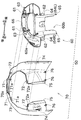
- FIG. 14 is an exploded perspective view showing a mounting structure of the dashboard 50.
- FIG. 15 is a diagram illustrating a state in which the dashboard support member 40 is attached to the fuel tank cover 30.
- FIG. 16 is a perspective view showing the configuration of the dashboard 50.
- a dashboard 50 is attached to a fuel tank cover 30 that covers a rear portion 19 c of the fuel tank 19 via a dashboard support member 40.
- the dashboard 50 can be directly attached to the fuel tank cover 30 without the dashboard support member 40 (details will be described later), and for easy understanding, the dashboard support member 40 is shown in FIG. It is drawn with a chain line.
- the fuel tank 19 is formed in a hollow shape by a synthetic resin, and as shown in FIG. 14, the fuel tank 19 includes a front portion 19 b provided with an oil filling port 19 a and a rear portion 19 c covered by a fuel tank cover 30.
- the A cover frame 24 to which the fuel tank cover 30 can be attached is provided between the front portion 19b and the rear portion 19c.
- the cover frame 24 may be formed integrally with the fuel tank 19 or may be attached to the fuel tank 19 as a separate part.
- the fuel tank cover 30 includes a cover portion 30a that covers the rear portion 19c of the fuel tank 19, and a frame portion 30b that extends from the edge of the cover portion 30a.
- the fuel tank cover 30 is disposed immediately behind the fuel tank 19 and is attached to the cover frame 24 by bolting or the like via the frame portion 30b.
- the cover portion 30a of the fuel tank cover 30 is formed in a shape along the shape of the rear portion 19c of the fuel tank 19. Moreover, the cover part 30a becomes a shape by which the front was open
- the cover portion 30a includes a first attachment portion (attachment portion) 31, a second attachment portion 34, a third attachment portion 35, as shown in FIG. A fourth attachment portion (operation panel portion attachment portion) 36 and a fifth attachment portion (operation panel portion attachment portion) 37 are formed.
- the first mounting portion 31 is provided one on each of the left and right sides of the upper portion of the cover portion 30a. As shown in FIGS. 14 and 15, each first mounting portion 31 has a flat surface portion 31 a that extends substantially horizontally along the front-rear direction of the cover portion 30 a.
- a front mounting portion 32 is provided at one end (front end) in the longitudinal direction of the flat surface portion 31a, and a rear mounting portion 33 is provided at the other end (rear end).
- the front attachment portion 32 is formed at the front end of the first attachment portion 31 (the end portion on the side close to the front portion 19b of the fuel tank 19), and is disposed so as to protrude above the flat portion 31a of the first attachment portion 31. Has been. As shown in FIG. 15, the front mounting portion 32 is formed so that the shape when viewed in the front-rear direction is a gate shape.
- An insertion space 32a is formed inside the portal portion.
- the insertion protrusion 73 (FIG. 16) of the dashboard 50 can be inserted into the insertion space 32a.
- the front mounting portion 32 is formed with a through hole that is elongated in the front-rear direction and opens the front end side for mounting bolts and the like.
- the rear attachment portion 33 is provided at the rear end of the first attachment portion 31. At the center position in the width direction, there is formed a through hole that is elongated in the front-rear direction and opens the rear end side for attaching a bolt or the like.
- the rear attachment portion 33 is disposed at a position slightly lower than the front attachment portion 32.
- a dashboard support member 40 that functions as a spacer is attached to the first attachment portion 31, and the dashboard 50 can be attached to the upper portion of the dashboard support member 40. . Thereby, the dashboard 50 can be arrange
- the second mounting portion 34 is provided on the left and right side surfaces of the fuel tank cover 30 at the front end portion at the lower end portion of the cover portion 30 a so as to protrude outward in the left-right direction of the fuel tank cover 30.
- the second attachment portion 34 is formed with a long hole that is elongated in the front-rear direction and opens the rear end side for attaching a bolt or the like.
- the third mounting portion 35 is provided on the left and right side surfaces of the fuel tank cover 30 slightly above the second mounting portion 34 so as to protrude outward in the left-right direction of the fuel tank cover 30.
- the third attachment portion 35 is formed with a long hole that is elongated in the front-rear direction and opens the rear end side for attaching a bolt or the like.
- the second mounting portion 34 and the third mounting portion 35 are provided in pairs on the left and right side surfaces of the fuel tank cover 30 with a predetermined interval in the vertical direction.
- the distance in the vertical direction between the centers of the long holes formed in the second mounting portion 34 and the third mounting portion 35 depends on whether the mounting position of the dashboard 50 depends on the presence or absence of the dashboard support member 40 described above. It is set to match the amount that changes.
- the fourth mounting portion 36 is formed on the rear side of the fuel tank cover 30 and on the left side so as to protrude rearward of the fuel tank cover 30.
- the fourth attachment portion 36 is formed with an insertion hole to which a bolt or the like can be attached.
- the fifth mounting portion 37 is formed on the rear surface of the fuel tank cover 30 and on the right side so as to protrude rearward of the fuel tank cover 30. As shown in FIG. 15, the fifth mounting portion 37 is formed with three insertion holes in which a bolt or the like can be mounted in the vertical direction.
- the dashboard support member 40 shown in FIG. 15 is formed of a metal flat plate member.
- the dashboard support member 40 includes a quadrangular main body 40a oriented such that the thickness direction is the left-right direction.
- the dashboard support member 40 includes a first lower mounting portion 45 and a second lower mounting portion 46 provided at the lower edge portion of the main body 40a, and a first upper mounting portion 47 provided at the upper edge portion of the main body 40a. And a second upper mounting portion 48.
- the first lower attachment portion 45 and the second lower attachment portion 46 are formed by bending small attachment portions extending downward at both front and rear direction end portions of the lower edge portion of the main body 40a so as to be perpendicular to the main body 40a. Is formed.
- the first lower mounting portion 45 and the second lower mounting portion 46 are oriented almost horizontally (in other words, parallel to the flat portion 31a of the first mounting portion 31 of the fuel tank cover 30). Further, the second lower mounting portion 46 is disposed at a position slightly lower than the first lower mounting portion 45. The first lower mounting portion 45 and the second lower mounting portion 46 are formed with through holes into which bolts or the like can be inserted.
- the distance in the front-rear direction between the first lower attachment portion 45 and the second lower attachment portion 46 is the front-rear direction between the front attachment portion 32 and the rear attachment portion 33 in the first attachment portion 31. It is set to match the distance.
- the vertical distance between the first lower mounting portion 45 and the second lower mounting portion 46 is such that the front mounting portion 32 (the upper surface of the front mounting portion 32) and the rear portion of the first mounting portion 31.
- the distance between the mounting portion 33 and the mounting portion 33 is set to coincide with the vertical distance. As described above, since the positional relationship between the attachment portions corresponds, the dashboard support member 40 can be reliably attached to the first attachment portion 31 at two locations.
- the first lower mounting portion 45 is mounted on the front mounting portion 32 and the second lower mounting portion 46 is mounted on the upper surface of the rear mounting portion 33.
- the long hole of the front attachment part 32 of the first attachment part 31 is bolted to the through hole of the second lower attachment part 46, and the long hole of the rear attachment part 33 is bolted. Thereby, the dashboard support member 40 can be easily attached to the fuel tank cover 30.
- the first upper mounting portion 47 and the second upper mounting portion 48 are formed by bending small mounting portions extending upward at both longitudinal ends of the upper edge of the main body 40a so as to be perpendicular to the main body 40a. Has been.
- the first upper mounting portion 47 and the second upper mounting portion 48 are oriented substantially horizontally (in other words, parallel to the first lower mounting portion 45 and the second lower mounting portion 46).
- a rectangular hole is formed in the first upper mounting portion 47 so as to penetrate in the vertical direction.
- an insertion protrusion 73 (FIG. 16) provided in the dashboard 50 can be inserted into the rectangular hole.
- the second upper mounting portion 48 is formed with a through hole into which a bolt or the like can be inserted.
- the dashboard 50 is attached to the dashboard support member 40 through the first upper attachment portion 47 and the second upper attachment portion 48 so as to cover the rear of the fuel tank cover 30 (details will be described later).
- the dashboard 50 is fitted with various instruments such as a speedometer and a fuel gauge, and is fitted to the operation panel 60 constituting the operation panel 10 of the tractor 100 and the outer periphery of the operation panel 60. And an outer peripheral board portion 70 fixed by joining.
- the operation panel unit 60 includes a main panel unit 60 a and an extending unit 60 b that extends downward from the center of the main panel unit 60 a.
- the main panel 60a has a panel surface facing rearward and upward.
- a pair of recesses 65 that can accommodate the protrusions 75 formed on the outer peripheral board portion 70 are formed at the lower end of the extending portion 60b and on the outer side in the left-right direction.
- an outer edge portion 66 is formed that is bent forward (the fuel tank cover 30 side when attached to the fuel tank cover 30).
- Two upper locking portions 61 and two lower locking portions 62 are formed on the outer edge portion 66 of the main panel portion 60a.
- the upper locking portion 61 and the lower locking portion 62 are configured to be engageable with the outer peripheral board portion 70.
- the two upper locking portions 61 and the two lower locking portions 62 are respectively formed at positions that are symmetrical with each other in the main panel portion 60a.
- the upper locking portion 61 is configured as a recess formed in a part of the outer edge portion 66 on the upper side of the main panel portion 60a.
- the lower locking portion 62 is configured as a quadrangular hole formed on the left and right sides of the extended portion 60b on the outer edge portion 66 on the lower side of the main panel portion 60a.
- the operation panel 60 has two first fixing parts (fixing parts) 63 and two second fixing parts 64. Yes.
- the first fixing portion 63 is provided on the outer edge portion 66 on the upper side of the main panel portion 60a at a position on the left and right outer sides from the two upper locking portions 61.
- the first fixing portion 63 is formed in a substantially horizontal flat plate extending forward from the main panel portion 60a.
- the first fixing portion 63 is formed with a through hole that is elongated in the front-rear direction and opens the front end side for attaching a bolt or the like.
- the two first fixing portions 63 are provided on the main panel portion 60a so as to correspond to the rear attachment portions 33 of the first attachment portions 31 provided on the left and right sides of the fuel tank cover 30, respectively. Therefore, the first fixing portion 63 and the rear mounting portion 33 of the first mounting portion 31 can be fixed to each other.
- the second fixing portion 64 is formed below the lower locking portion 62 and has a plate shape extending downward.
- the second fixing portion 64 is formed with a through hole that is elongated in the vertical direction and opens the lower end side for attaching a bolt or the like.
- the second fixing portion 64 provided on the left side of the main panel portion 60a is referred to as a left fixing portion 64L
- the second fixing portion 64 provided on the right side of the main panel portion 60a is referred to as the right fixing portion. May be referred to as 64R.
- the outer peripheral board portion 70 is configured to cover the outer periphery of the fuel tank cover 30.
- An opening 70 a to which the operation panel unit 60 can be fitted and attached is formed at the center of the outer peripheral board unit 70.
- Both the upper mounting portion 71 and the lower mounting portion 72 are formed as small members that extend obliquely from the edge of the opening 70a toward the front lower side.
- Locking claws 71 a and 72 a for preventing the upper mounting portion 71 and the lower locking portion 62 from coming off are formed at the tips of the upper mounting portion 71 and the lower mounting portion 72, respectively.
- the upper mounting portion 71 is inserted into the upper locking portion 61 of the operation panel portion 60 and hooked by the locking claw 71a, and the lower mounting portion 72 is hooked by the lower locking portion 62 of the operation panel portion 60.
- the outer peripheral board portion 70 can be fixed to the operation panel portion 60 by being inserted into the hook and hooked by the locking claws 72a.
- the outer peripheral board part 70 is formed with an insertion projection (fixed part) 73 and an attachment opening 74.
- one insertion protrusion 73 is provided on the inner peripheral surface of the upper portion of the outer peripheral board portion 70 at positions that are symmetrical with respect to each other across the top.
- Each insertion protrusion 73 is formed in a small plate shape that extends obliquely from the inner peripheral surface of the outer peripheral board portion 70 toward the front lower side.
- the two insertion protrusions 73 are disposed at positions corresponding to the front mounting portions 32 of the first mounting portions 31 provided on the left and right sides of the upper portion of the fuel tank cover 30.
- the mounting opening 74 is formed as a penetrating long hole disposed on the left and right sides of the front edge of the outer peripheral board portion 70 for mounting a bolt or the like.
- Each attachment opening 74 is formed so as to extend obliquely from the front edge of the outer peripheral board 70 toward the rear upper side.
- the attachment opening 74 is located at a position corresponding to the third attachment portion 35 of the fuel tank cover 30 when the outer peripheral board portion 70 is attached to the fuel tank cover 30 with the dashboard support member 40 interposed as in the present embodiment. Is arranged.
- the second mounting portion 34 is disposed below the third mounting portion 35, and as described above, the distance between the third mounting portion 35 and the second mounting portion 34 is the mounting position of the dashboard 50. Is set to coincide with the amount that changes in the vertical direction depending on the presence or absence of the dashboard support member 40 described above. Therefore, when the dashboard 50 is attached through the dashboard support member 40, the attachment opening 74 can be fixed to the third attachment portion 35, while when the dashboard 50 is attached without the dashboard support member 40. The attachment opening 74 can be fixed to the second attachment portion 34.
- the dashboard 50 can be attached to the fuel tank 19 and the fuel tank cover 30 at different positions in the vertical direction depending on whether or not the dashboard support member 40 is interposed. That is, most of the configuration of the tractor 100 of the present embodiment can be diverted to easily configure a tractor of another specification in which the dashboard 50 is low.
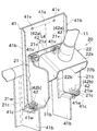
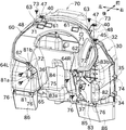
- FIG. 17 is a perspective view showing a state in which the dashboard 50 is attached to the fuel tank cover 30 via the dashboard support member 40.
- the outer peripheral board portion 70 is shown in a perspective manner with a chain line in FIG.
- the dashboard 50 can be disposed at a relatively high position by attaching the dashboard support member 40 to the fuel tank cover 30.
- a pair of dashboard support members 40 are attached to the fuel tank cover 30 by bolting to the long holes and bolting through holes formed in the second lower attachment portion 46 to the long holes of the rear attachment portion 33. .
- the left attachment member (attachment member) 81 and the right attachment member (attachment member) 82 for attaching the operation panel portion 60 of the dashboard 50 are used as the fourth attachment portion 36 and the fifth attachment portion 37 of the fuel tank cover 30. Attach to each.
- the left side attachment member 81 is formed of an elongated plate member, and is attached to the fuel tank cover 30 so that the longitudinal direction thereof is up and down.
- a lower attachment hole (attachment hole) 81a is formed below the left attachment member 81, and an upper attachment hole (attachment hole) 81b is formed on the upper side.
- Bolts can be inserted into the lower mounting hole 81a and the upper mounting hole 81b.
- the center-to-center distance between the lower mounting hole 81a and the upper mounting hole 81b is 1 ⁇ 2 of the amount that the mounting position of the dashboard 50 changes in the vertical direction depending on the presence or absence of the dashboard support member 40 described above. Is set to
- the right mounting member 82 includes a starter switch support member 83 that supports a starter switch 124 (see FIGS. 4 and 6) that is a switch for starting the engine 5, and a bent member formed by bending an elongated plate member. 84.
- the starter switch support member 83 is formed of a plate-like member, and is arranged in an upright posture so that the thickness direction is front and rear.
- the starter switch support member 83 is formed with a penetrating support hole 85 for supporting the starter switch.
- the starter switch support member 83 is formed with a lower mounting hole (mounting hole) 83a and an upper mounting hole (mounting hole) 83b arranged side by side in the vertical direction. Yes.
- the bending member 84 is formed by bending an elongated plate member into an L-shape, and is disposed so that the thickness direction on one side is left and right, and is disposed so that the thickness direction on the other side is front and rear. . And the part arrange
- the portion of the bending member 84 that is disposed so that the thickness direction is front and rear is disposed so as to protrude forward from the starter switch support member 83. Further, a through hole into which a bolt or the like can be inserted is formed in the protruding portion.
- the lower attachment hole 81 a of the left attachment member 81 is bolted to the fourth attachment portion 36 of the fuel tank cover 30. Fixed. Further, the lower mounting hole 83a of the right mounting member 82 is fixed by bolting to the central insertion hole among the three insertion holes arranged in the vertical direction as shown in FIG. As described above, the left attachment member 81 and the right attachment member 82 are attached to the fuel tank cover 30.
- the operation panel 60 is attached. Specifically, as shown in FIG. 17, the second upper mounting portion of the dashboard support member 40 in which the long holes of the first fixing portion 63 arranged on the left and right of the operation panel portion 60 are arranged in a pair on the left and right. Each of the 48 through holes is bolted. Further, the long hole formed in the left side fixing portion 64L of the operation panel portion 60 is bolted to the upper side mounting hole 81b of the left side mounting member 81, and the long hole formed in the right side fixing portion 64R of the operation panel portion 60 is The right attachment member 82 is bolted to the through hole formed in the bending member 84.
- the outer peripheral board part 70 is attached. Specifically, the insertion protrusion 73 of the outer peripheral board portion 70 is inserted into a rectangular hole formed in the first upper mounting portion 47 of the dashboard support member 40. Further, the upper mounting portion 71 and the lower mounting portion 72 are inserted into the upper locking portion 61 and the lower locking portion 62 of the operation panel 60, respectively, and fixed by being hooked.
- the attachment opening 74 formed in the outer peripheral board portion 70 is bolted to the third attachment portion 35 of the fuel tank cover 30.
- the attachment opening 74 is configured so that the position of the attachment opening 74 coincides with the third attachment part 35 of the fuel tank cover 30. 3
- the mounting portion 35 can be bolted without any problem.
- cover members 86 that cover the lower part that is not covered by the dashboard 50 are provided on the left and right. Each cover member 86 is provided so as to be connected to the lower end of the dashboard 50 and the lower end of the fuel tank cover 30.
- a cover mounting portion 76 is provided at the lower end portion of the outer peripheral board portion 70 as shown in FIG. As shown in FIG.
- the cover member 86 is fixed to the cover attaching portions 76 and 38 by, for example, screwing. With this configuration, it is possible to suitably cover a portion exposed below the dashboard 50 and the fuel tank cover 30.
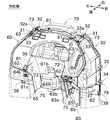
- FIG. 18 is a perspective view showing a tractor according to another specification in which the dashboard 50 is directly attached to the fuel tank cover 30.
- the outer peripheral board portion 70 is also perspectively drawn with a chain line in FIG. 18 as in FIG.
- the dashboard 50 is disposed at a relatively low position as compared with the case where the dashboard support member 40 is interposed by directly attaching the dashboard 50 to the fuel tank cover 30. become.
- the left side attachment member 81 and the right side attachment member 82 are attached to the fourth attachment part 36 and the fifth attachment part 37 of the fuel tank cover 30, respectively.
- the positions at which the left attachment member 81 and the right attachment member 82 are attached to the fuel tank cover 30 are different from those in FIG. That is, the upper attachment hole 81b (not the lower attachment hole 81a) of the left attachment member 81 is fixed to the fourth attachment portion 36 of the fuel tank cover 30 by bolting.
- the two upper mounting holes 83b (not the lower mounting holes 83a) of the right mounting member 82 are inserted at positions other than the center of the three insertion holes arranged in the vertical direction as shown in FIG. It is fixed to the hole by bolting.
- the left mounting member 81 and the right mounting member 82 are attached to the fuel tank cover 30. Since the left mounting member 81 is mounted on the fourth mounting portion 36 so as to extend in the direction opposite to the case of FIG. 17, the distance between the lower mounting hole 81a and the upper mounting hole 81b is set small.
- the dashboard 50 can be attached to the fuel tank cover 30 in both cases of FIGS.
- the long holes of the first fixing portions 63 arranged on the left and right of the operation panel portion 60 are respectively bolted to the long holes of the rear mounting portion 33 of the first mounting portion 31 in the fuel tank cover 30. Stopped. Further, the long hole formed in the left side fixing portion 64L of the operation panel portion 60 is bolted to the lower side mounting hole 81a of the left side mounting member 81, and the long hole formed in the right side fixing portion 64R of the operation panel portion 60 is formed. The bolts are bolted to the through holes formed in the bending member 84 of the right mounting member 82.
- the outer peripheral board portion 70 of the dashboard 50 is attached. Specifically, as shown in FIG. 18, the insertion protrusion 73 of the outer peripheral board portion 70 is inserted into the insertion space 32 a of the front attachment portion 32 of the first attachment portion 31. Further, the upper mounting portion 71 and the lower mounting portion 72 are inserted into the upper locking portion 61 and the lower locking portion 62 of the operation panel 60, respectively, and fixed by being hooked.
- the mounting opening 74 formed in the outer peripheral board portion 70 is bolted to the second mounting portion 34 of the fuel tank cover 30.
- the attachment opening 74 is configured so that the position of the attachment opening 74 coincides with the second attachment portion 34 of the fuel tank cover 30. 2 It can fix to a mounting part 34 with a volt
- the cover member 86 attached in FIG. 17 is omitted.
- the existing dashboard 50 and the fuel tank cover 30 can be used for the tractor of another specification shown in FIG. 18, and the labor and cost for parts management can be greatly reduced.
- the tractor 100 includes the fuel tank 19, the fuel tank cover 30, the dashboard support member 40, and the dashboard 50.
- the fuel tank 19 is provided in the rear part of the bonnet 9 in the front-rear direction of the body 2.
- the fuel tank cover 30 covers the rear portion 19 c of the fuel tank 19.
- the dashboard support member 40 is attached to the fuel tank cover 30.
- the dashboard 50 is supported by the dashboard support member 40.
- the fuel tank cover 30 includes a first attachment portion 31 for attaching the dashboard support member 40.
- the dashboard 50 can be directly attached to the first attachment portion 31.
- the dashboard 50 can be arranged at different positions depending on whether or not the dashboard support member 40 is interposed.
- the dashboard 50, the fuel tank cover 30 and the like in the tractor 100 of the present embodiment can be diverted even to a tractor of another specification (FIG. 18) having a different arrangement position of the dashboard 50. 50, the design change of the fuel tank cover 30 and the like are not required, and labor and cost can be reduced.
- the dashboard 50 can be attached to different positions with a simple configuration in which the presence or absence of the dashboard support member 40 is simply switched.
- the dashboard 50 is provided with a first fixing portion 63 and an insertion protrusion 73 formed so as to be directly attached to the first attachment portion 31 of the dashboard support member 40 in the fuel tank cover 30. Is provided.
- the dashboard support member 40 supports the dashboard 50 via the first fixing portion 63 and the insertion protrusion 73 of the dashboard 50.
- the first fixing portion 63 and the insertion protrusion 73 attached to the dashboard support member 40 are used as fixing means when the dashboard 50 is directly attached to the fuel tank cover 30 without the dashboard support member 40. can do. Therefore, the dashboard 50 can be mounted in different positions with a simple and compact configuration.
- the dashboard support member 40 is composed of a plate member, and is attached to each of the left and right sides of the upper portion of the fuel tank cover 30 one by one.
- the dashboard 50 can be attached to a plurality of positions in the vertical direction depending on the presence or absence of the dashboard support member 40.
- the dashboard support member 40 can be easily formed, and the dashboard 50 can be stably supported at a high position.
- the tractor 100 of the present embodiment includes a cover member 86 that is connected to the lower end portion of the dashboard 50 and covers a space below the space between the dashboard 50 and the fuel tank cover 30.
- the cover member 86 is configured as a member different from the dashboard 50, in another specification (FIG. 18) in which the dashboard 50 is mounted at a low position, the cover member 86 is omitted and a compact configuration is provided. Can be realized.
- the dashboard 50 includes an operation panel unit 60 and an outer peripheral board unit 70 fixed to the operation panel unit 60.
- the fuel tank cover 30 further includes a fourth attachment portion 36 and a fifth attachment portion 37 for attaching the operation panel portion 60.
- the fourth attachment portion 36 and the fifth attachment portion 37 are provided separately from the first attachment portion 31.
- the operation panel portion 60 is attached to the fourth attachment portion 36 and the fifth attachment portion 37 of the fuel tank cover 30 via the left attachment member 81 and the right attachment member 82.
- the left side mounting member 81 and the right side mounting member 82 can be adjusted appropriately at different positions of the operation panel unit 60 with respect to the fuel tank cover 30. Can be easily installed.
- the left side mounting member 81 and the right side mounting member 82 are formed from plate members.
- the left attachment member 81 has a lower attachment hole 81a and an upper attachment hole 81b attached to the fourth attachment portion 36.
- the right attachment member 82 has a lower attachment hole 83a and an upper attachment hole 83b attached to the fifth attachment portion 37.
- the left side mounting member 81 and the right side mounting member 82 can be configured easily. Further, switching of the mounting position of the operation panel 60 of the dashboard 50 can be realized with a simple configuration.
- the distance between the lower mounting hole 81a and the upper mounting hole 81b formed in the left mounting member 81 depends on whether the dashboard 50 is mounted on the dashboard support member 40 or not.
- the amount of change is 1 ⁇ 2.
- the switching of the height at which the dashboard 50 is mounted can be realized with the compact configuration of the left mounting member 81.
- the right mounting member 82 supports the starter switch 124 for starting the engine 5 provided in the body 2 of the tractor 100.
- the mounting position (height) of the dashboard 50 may be switched to three or more stages instead of two stages.
- the pair of left and right dashboard support members 40 may be connected by, for example, a horizontal bar-shaped member.
- the upper portion of the dashboard support member 40 has an elongated flat surface portion in the front-rear direction, and a portal-shaped front mounting portion is formed at the front end thereof.
- a configuration in which a rear mounting portion is formed may be employed.
- a horizontal flat plate portion with a long hole such as the first fixing portion 63 may be formed. It is also possible to form protrusions on the dashboard support member 40 side (fuel tank cover 30 side) and to form through holes or recesses on the dashboard 50 side, thereby fixing both.
- the fuel tank 19 is provided with the cover frame 24, and the fuel tank cover 30 is attached to the cover frame 24.
- the cover frame 24 can be omitted if the fuel tank cover can be disposed so as to cover the rear portion 19c of the fuel tank 19.
- a long hole for inserting a bolt or the like is formed, and this long hole has a shape in which one end is opened.
- this long hole can be changed to a long hole having a closed shape at both ends. Further, the long hole can be changed to a round hole.
- at least one of the holes bolted to each other is a long hole so that the dimensional error of the dashboard 50 and the fuel tank cover 30 can be absorbed.
- the present invention is not limited to a tractor, but can be applied to various work vehicles such as rice transplanters, combines, and wheel loaders.
- Airframe (car body) 9 Bonnet 19 Fuel tank 30 Fuel tank cover 31 First mounting portion (mounting portion) 36 Fourth mounting section (operation panel mounting section) 37 Fifth mounting part (operation panel part mounting part) 40 Dashboard support member (support member) 50 Dashboard 60 Operation panel 63 First fixing part (fixing part) 70 Peripheral board part 73 Insertion protrusion (fixing part) 81 Left mounting member (Mounting member) 81a Lower mounting hole (Mounting hole) 81b Upper mounting hole (Mounting hole) 82 Right side mounting member (Mounting member) 83a Lower mounting hole (Mounting hole) 83b Upper mounting hole (Mounting hole) 100 Tractor (work vehicle) 124 Starter switch (Engine starter switch)
Landscapes
- Engineering & Computer Science (AREA)
- Chemical & Material Sciences (AREA)
- Combustion & Propulsion (AREA)
- Transportation (AREA)
- Mechanical Engineering (AREA)
- Life Sciences & Earth Sciences (AREA)
- Sustainable Development (AREA)
- Sustainable Energy (AREA)
- Body Structure For Vehicles (AREA)
- Cooling, Air Intake And Gas Exhaust, And Fuel Tank Arrangements In Propulsion Units (AREA)
- Instrument Panels (AREA)
Abstract
トラクタは、燃料タンク(19)と、燃料タンクカバー(30)と、ダッシュボード支持部材(40)と、ダッシュボード(50)と、を備える。燃料タンク(19)は、トラクタの機体の前後方向においてボンネット内の後部に設けられる。燃料タンクカバー(30)は、燃料タンク(19)の後部を覆う。ダッシュボード支持部材(40)は、燃料タンクカバー(30)に取り付けられる。ダッシュボード(50)は、ダッシュボード支持部材(40)に支持される。燃料タンクカバー(30)は、ダッシュボード支持部材(40)を取り付けるための第1取付部(31)を備える。ダッシュボード(50)は、(ダッシュボード支持部材(40)なしで)第1取付部(31)に直接取り付けることも可能に構成されている。
Description
本発明は、ダッシュボードを備えた作業車両に関する。
従来から、作業車両の運転座席の近傍において、ステアリングハンドルの前方にダッシュボードが設置される構造が知られている。典型的な構成において、ダッシュボードには操作パネルが配置され、操作パネルはコンビネーションメータを有している。特許文献1は、作業車両ではなく乗合バスに係るものであるが、変位可能に配置されたダッシュボードを備える自動車を開示する。
特許文献1の自動車においては、ステアリングコラム及びダッシュボードは互いに相対運動可能ではなく、むしろ昇降可能かつ旋回可能な1つの構成ユニットを形成しており、当該構成ユニットが、適当な滑子案内を介して移動調整可能であり、かつあらゆる位置でロック可能である構成となっている。
特許文献1において、ダッシュボードに所属して安定化装置を配置してある。安定化装置が備える前記滑子案内は、互いに著しく離隔して位置する案内レールに備えられ、この滑子案内は歯車/ラック結合部と組み合わされている。
上記特許文献1では、ステアリングコラム及びダッシュボードが互いに相対運動可能ではなく、1つの構成ユニットとして形成されている。このため、特許文献1の構成は、ダッシュボードの位置が異なる複数の仕様の作業車両を製造する場合に必ずしも好適であるとはいいがたい。また、特許文献1において、ステアリングコラム及びダッシュボードからなる構成ユニットを調整するためには滑子案内等の装置が必要であるため、その調整構造が複雑になり、コストの面でも不利であった。
本発明は以上の事情に鑑みてされたものであり、その目的は、簡素な構成で、ダッシュボードの位置が異なる別の仕様を容易に実現可能な作業車両を提供することにある。
本発明の解決しようとする課題は以上の如くであり、次にこの課題を解決するための手段とその効果を説明する。
本発明の観点によれば、以下の構成の作業車両が提供される。即ち、この作業車両は、燃料タンクと、燃料タンクカバーと、支持部材と、ダッシュボードと、を備える。前記燃料タンクは、車体の前後方向においてボンネット内の後部に設けられる。前記燃料タンクカバーは、前記燃料タンクの後部を覆う。前記支持部材は、前記燃料タンクカバーに取り付けられる。前記ダッシュボードは、前記支持部材に支持される。前記燃料タンクカバーは、前記支持部材を取り付けるための取付部を備える。前記ダッシュボードを、前記取付部に直接取り付けることができる。
これにより、支持部材の介在の有無によって、ダッシュボードを異なる位置に配置可能な構成を実現することができる。この結果、ダッシュボードの配置位置が異なる別仕様の作業車両に対しても、ダッシュボード及び燃料タンクカバー等の流用が可能になるので、ダッシュボード及び燃料タンクカバーの設計変更等が不要になり、手間及びコスト等を削減することができる。また、支持部材の取付けの有無を切り換えるだけの簡単な構成で、ダッシュボードを異なる位置に取り付けることができる。
前記の作業車両においては、以下の構成とすることが好ましい。即ち、前記ダッシュボードは、前記燃料タンクカバーにおける前記支持部材の前記取付部に直接取り付けることが可能に形成された固定部を備える。前記支持部材は、前記ダッシュボードの前記固定部を介して、前記ダッシュボードを支持する。
これにより、支持部材に対して取り付けられているダッシュボードの固定部を、ダッシュボードを支持部材なしで燃料タンクカバーに直接取り付ける場合の固定手段として利用することができる。従って、ダッシュボードの異なる位置への取付けを簡単かつコンパクトな構成で実現できる。
前記の作業車両においては、以下の構成とすることが好ましい。即ち、前記支持部材は、板部材から構成され、前記燃料タンクカバーの上部の左右両側にそれぞれ1つずつ取り付けられている。前記支持部材の介在の有無により、前記ダッシュボードを上下方向における複数の位置に取り付けることができる。
これにより、支持部材を容易に形成することができるとともに、ダッシュボードを高い位置で安定的に支持することができる。
前記の作業車両においては、前記ダッシュボードの下端部に接続され、当該ダッシュボードと前記燃料タンクカバーとの間より下方の空間を覆うカバー部材を備えることが好ましい。
これにより、支持部材によって相対的に高く取り付けられたダッシュボードの下方において、部品等をカバー部材によって好適に覆うことができる。また、カバー部材をダッシュボードとは別の部材とすることにより、ダッシュボードを低い位置に取り付けた別仕様においては、カバー部材を省略してコンパクトな構成を実現することができる。
前記の作業車両においては、以下の構成とすることが好ましい。即ち、前記ダッシュボードは、操作パネル部と、外周ボード部と、を備える。前記外周ボード部は、前記操作パネル部に固定される。前記燃料タンクカバーは、前記操作パネル部を取り付けるための操作パネル部取付部を前記取付部とは別に備える。前記操作パネル部は、取付部材を介して、前記燃料タンクカバーの前記操作パネル部取付部に取り付けられている。
これにより、操作パネル部又は燃料タンクカバーの構成を変更せずに、取付部材を適切に調整するだけで、燃料タンクカバーに対して当該操作パネル部を異なる位置に取り付けることを容易に実現できる。
前記の作業車両においては、前記取付部材は、板状に形成され、前記操作パネル部取付部に取り付けることができる取付孔を複数有することが好ましい。
これにより、取付部材を簡単に形成することができるとともに、シンプルな構成でダッシュボードの操作パネル部を異なる位置に取り付けることを実現できる。
前記の作業車両においては、前記取付部材には、複数の取付孔の間の距離が、前記ダッシュボードの取付位置が前記支持部材の有無に応じて変化する量の1/2となっている部材が含まれることが好ましい。
これにより、ダッシュボードの取付位置の切換を、コンパクトな取付部材の構成で実現することができる。
前記の作業車両においては、前記取付部材には、前記車体が備えるエンジンを始動するためのエンジンスタータスイッチを支持する部材が含まれることが好ましい。
これにより、構成の簡素化を実現することができる。
次に、図面を参照して本発明の実施の形態を説明する。まず、本発明の一実施形態に係るトラクタ100の構成について簡単に説明する。図1は、トラクタ100の全体的な構成を示す左側面図である。なお、以下の説明において「左」、「右」等というときは、トラクタ100が前進する方向に向かって左及び右を意味する。
図1に示す農作業用の作業車両としてのトラクタ100は、プラウ、ローダ等の様々な作業装置を必要に応じて装着し、様々な種類の作業を行うことが可能に構成されている。
このトラクタ100は、図1に示すように、機体(車体)2と、左右1対の前輪3と、左右1対の後輪4と、を備える。前輪3は機体2の前部を支持し、後輪4は機体2の後部を支持している。
トラクタ100の機体2の前部にはボンネット9が配置され、このボンネット9は内部を露出できるように開閉可能に構成されている。ボンネット9は流線形状に構成されており、その前部は、前方に近づくに従って上下方向でも左右方向でも細くなるように形成されている。この形状により、走行時の空気抵抗の低減と意匠性の向上が実現されている。
このボンネット9内には、燃料タンク19の一部と、エンジン5と、が収容されている。また、エンジン5の前方には、ファンシュラウド110と、ラジエータ111と、コンデンサ112と、エンジンコントロールユニット(ECU)113と、エアクリーナ114と、バッテリー115と、が配置されている。ファンシュラウド110、コンデンサ112、エンジンコントロールユニット(ECU)113、エアクリーナ114、及びバッテリー115は、エンジンフレーム16に固定された図略の取付プレートの上側に後方から前方に向かって上記の順で配置され、何れもボンネット9に収容されている。
燃料タンク19は、エンジン5の上部に配置されている。燃料タンク19は、上部に注油口19aを有しており、ここから注油が行われる。この注油口19aは、図1に示すように、ボンネット9の上部に設けられた孔から突出するように配置されているため、オペレータはボンネット9の開閉状態に依存せず注油作業を行うことが可能となっている。
また、図1に示すように、当該燃料タンク19の前部19bは、ボンネット9の内部空間において、エンジン5の上方に配置されている。また、燃料タンク19の後部19cは、燃料タンクカバー30によりカバーされ、キャビン6に設けられたダッシュボード50の内部に配置されている。
エンジン5は、複数のシリンダを有するコモンレール式のディーゼルエンジンとして構成されている。具体的に説明すると、エンジン5は、燃料タンク19から供給された燃料を高圧で蓄える図略のコモンレールを備える。コモンレールから供給された燃料は、シリンダ毎に配置された図示しないインジェクタにより、シリンダ内の燃焼室に燃料を噴射する。
ファンシュラウド110は、エンジン5により駆動される冷却ファンの外周を覆うように構成され、エンジン5の前方に配置されている。このファンシュラウド110の右上側には、エンジン5の吸気パイプ116等の部材を通すための図示しない切欠部が設けられている。また、ファンシュラウド110は、ボンネット9の内部区間を前後に区画するように構成されている。従って、ファンシュラウド110の前方に配置された装置(ラジエータ111やコンデンサ112等)に対して、エンジン5からの熱を遮蔽することができる。
ラジエータ111は、エンジン5のウォータージャケット内の冷却水を冷却する装置であって、ラジエータ111の前面側に取り付けられている。このラジエータ111と、エンジン5に形成された図略のウォータージャケットと、の間には、冷却水を循環させる図略の循環経路が形成されている。エンジン5の発熱によって高温になった前記ウォータージャケット内の冷却水は、ラジエータ111へ送られる。冷却水は、ラジエータ111を通過する際に図示しないフロントグリルから取り込まれた外気によって冷却された後、再び前記ウォータージャケットへ戻り、エンジン5を冷却する。
コンデンサ112は熱交換器として構成されており、キャビン6内の空調を行うエアコンディショナに用いられる高圧の液状冷媒を通過させるチューブと、当該チューブの周囲にコルゲート式又はプレート式等で構成されるフィンと、を主要な構成として備えている。このコンデンサ112は、図略のコンデンサフレームにより支持され、ラジエータ111の前側に取り付けられている。
ECU113は、小型のコンピュータとして構成されている。ECU113は、エンジン5に取り付けられている様々なセンサからの情報に基づいて、燃料噴射量、燃料噴射時期等を制御する制御指令を出すことによりエンジン5の稼動を制御する。
エアクリーナ114は、空気中の異物を除去するためのエアクリーナエレメントを内部に収容した構成となっている。このエアクリーナ114は吸気パイプ116によってエンジン5に接続されており、エンジン5の吸気構造の一部を構成している。
バッテリー115は、トラクタ100が備える各種の電気部品(例えば、エンジン5が備えるセルモータ、トラクタ100の前照灯、ECU113等)に対して電力を供給する。
図1に示すように、機体2の後部にはオペレータが搭載するためのキャビン6が設置されている。このキャビン6の内部には、オペレータが操舵するためのステアリングハンドル7と、オペレータが座る運転座席8と、各種の操作を行うための様々な操作装置と、が設けられている。
上記の操作装置として、例えば、ステアリングハンドル7の前方に配置された操作パネル10等を挙げることができる。当該操作パネル10は、ステアリングハンドル7の前方に配置されたダッシュボード50に固定されている。操作パネル10には、図略のスピードメーター、燃料計、距離計等、トラクタ100の走行に必要な情報を示す計器類等が配置されている。
機体2の骨格を構成する機体フレームは、エンジンフレーム16と、ミッションケース18と、を備える。エンジンフレーム16の下側には、前車軸ケース17が取り付けられている。前車軸ケース17には、前車軸130を介して前輪3が取り付けられている。ミッションケース18には、後車軸14を介して後輪4が取り付けられている。左右の後輪4の上方は、左右のリアフェンダー121によって覆われている。
図6に示すように、エンジンフレーム16及びミッションケース18はそれぞれ細長い形状に構成され、何れも、その長手方向が前後方向になるように配置されている。ミッションケース18は、適宜の固定部材を介してエンジンフレーム16の後端に固定されている。そして、上記で説明したように、エンジンフレーム16は前車軸ケース17及び前車軸130を介して前輪3により支持され、ミッションケース18は後車軸14を介して後輪4により支持されている。このように、前輪3及び後輪4が、エンジンフレーム16とミッションケース18とから構成される機体フレームを支持している。
このミッションケース18は、エンジン5からの動力を減速して前車軸ケース17や後車軸14に伝達する。オペレータが図示しない変速操作具を操作することにより、当該ミッションケース18における変速比を変更し、トラクタ100の走行速度を調整することができる。
図2に示すように、ミッションケース18の後端から突出するようにPTO軸118が配置されており、エンジン5の駆動力は、このPTO軸118に伝達される。トラクタ100は、その後端に上述の作業装置を装着可能に構成されている。PTO軸118は、作業装置を、図示しないユニバーサルジョイント等を介して駆動することができる。
このように構成されたトラクタ100は、田圃で走行しながら、耕耘、播種、収穫等様々な作業を行うことができる。
次に、図2等を参照して、本実施形態のダッシュボード50及びその後方に配置されたステアリングコラムの配置構成について簡単に説明する。図2は、トラクタ100の構成を示す斜視図である。
図2に示すように、本実施形態のダッシュボード50は、ボンネット9の後方であって、キャビン6の内部の前側の中央に取り付けられている。当該ダッシュボード50は、燃料タンク19の後部19cをカバーする燃料タンクカバー30を覆うように取り付けられている(詳細は後述する)。
ダッシュボード50の後方には、ステアリングコラム11を覆うカバー(ステアリングコラムカバー123)が設置されている。ステアリングコラムカバー123の上方であって、ダッシュボード50の斜め後上方には、ステアリングハンドル7が配置されている。
ダッシュボード50の後部は、左右中央に配置されたステアリングコラムカバー123の前側を取り囲むような形状に形成される。ステアリングコラムカバー123は、その前部がダッシュボード50の後部に一部埋め込まれるように配置される。これにより、ダッシュボード50及びステアリングコラムカバー123の上部に取り付けられたステアリングハンドル7から構成される操作部のコンパクト化を実現し、オペレータの居住空間を広く確保することができる。
図3及び図4に示すように、キャビン6は、骨組状のキャビンフレーム122を備えている。このキャビンフレーム122は、トラクタ100が備えるミッションケース18に固定されている。ステアリングコラム11は、キャビンフレーム122により支持固定されている。
具体的には、図5に示すように、キャビンフレーム122は左右1対のフレーム固定部材132を介してミッションケース18の左右側面に固定されている(ただし、図5には、右側のフレーム固定部材132のみが示されている)。フレーム固定部材132は略L字形に形成されており、板状のミッションケース取付部132aと、板状のフレーム取付部132bと、を備えている。ミッションケース取付部132aは、その厚み方向を機体左右方向に向けて配置され、ミッションケース18の側面にボルト等を介して取り付けられている。一方、フレーム取付部132bは、その厚み方向を上下方向に向けて配置され、キャビンフレーム122を構成する底部板部材122aを支持するように、当該底部板部材122aの底面に取り付けられている。このように、キャビンフレーム122はミッションケース18に固定され、ミッションケース18を介して後輪4により支持されている。
ステアリングコラム11は、図5に示すブラケット20に固定されている(なお、ステアリングコラム11を分かり易く示すために、図5においてはステアリングコラムカバー123を鎖線で透視的に示している)。キャビンフレーム122にはフレーム板部材134がボルト等によって固定されており、前記ブラケット20は、支持部材41を介して、上記のフレーム板部材134に固定されている。このように、ステアリングコラム11は、支持部材41等の部材を介して、キャビンフレーム122に支持固定されている。
図6に示すように、本実施形態のダッシュボード50は、後述のダッシュボード支持部材40の介在の有無を切り換えることによって、互いに異なる複数の仕様のトラクタに適用することができる。そして、ステアリングコラム11及びステアリングコラムカバー123においても、その取付け位置を適切に変更することによって、互いに異なる複数の仕様のトラクタに適用することができる。
次に、図7及び図8を参照して、ダッシュボード50内に配置されるステアリングコラム11及びブラケット20の構成を説明する。図7は、ステアリングコラム11及びブラケット20の周辺の構成を示す左側面図である。図8は、ステアリングコラム11及びブラケット20の周辺の構成を示す斜視図である。なお、図7及び図8においては、ダッシュボード50が取り外された状態が示されている。
ダッシュボード50の内部には、細長い円筒形のステアリングコラム11が配置されている。このステアリングコラム11は、ステアリングハンドル7の下方に、当該ステアリングハンドル7の回転軸と一致する向きで配置されている。ステアリングコラム11の下端部は、ブラケット20に支持されている。
ステアリングコラム11は中空状に形成されており、その内部には、図示しない棒状のステアリングシャフトが配置されている。ステアリングシャフトの上部にはステアリングハンドル7が取り付けられている。ステアリングシャフトの下部はステアリングコラム11に差し込まれるとともに、当該ステアリングコラム11に対して回転可能に支持されている。ステアリングコラム11の上部には、トラクタ100が備える図略の前後進切替機構を操作するためのリバーサレバー12が取り付けられている。また、ステアリングコラム11には、ステアリングコラム11の長手方向におけるステアリングハンドル7の位置を調整するための公知のテレスコピック装置13が配置されている。
ステアリングハンドル7は、丸ハンドル形状に構成されており、左右両方向に回転操作できるように構成されている。ステアリングハンドル7の回転は、前記ステアリングシャフトを介して、図略のパワーステアリング装置が備えるステアリングバルブユニットに入力される。ステアリングバルブユニットは、パワーステアリング装置のシリンダに対する作動油の供給を切り換える。これにより、ステアリングハンドル7が回転操作された方向及び角度に応じて、シリンダが駆動されて前輪3の方向が変更され、トラクタ100の進行方向を変更することができる。
リバーサレバー12は、ステアリングコラム11の上部左側に配置されている。このリバーサレバー12は、ステアリングコラム11から左側に突出するように取り付けられ、略上下方向に向けられた軸を中心にして回転可能に構成されている。トラクタ100は、リバーサレバー12の操作を検出するための図示しないリバーサスイッチを備えている。この構成で、オペレータがリバーサレバー12を前又は後に操作することにより、トラクタ100が備える図略の前後進切換機構が制御され、トラクタ100の進行方向を前又は後に切り換えることができるようになっている。
ブラケット20は、ステアリングコラム11を、トラクタ100のエンジンフレーム16に固定されている支持部材41に対して支持している。このブラケット20は、図7及び図8に示すように、ベース部材21と、可動部材22と、を備える。
ベース部材21は、支持部材41に対し、複数(本実施形態では、4つ)の防振ゴム42を介して取り付けられている。
可動部材22は、ベース部材21の上部に、左右1対で配置された軸部材26を介して取り付けられている。可動部材22は、軸部材26の軸(左右水平方向に配置された回転軸27)を中心として回転可能となるように支持されている。なお、この回転軸27が、ブラケット20が備えるチルト機構のチルト軸に相当する。可動部材22の上部には、前記ステアリングコラム11の下端部が固定される。この構成で、可動部材22を回転させることにより、ステアリングコラム11及びステアリングハンドル7を後方に倒したり、前方に起こしたりすることができる(チルト機能)。ブラケット20が備える上記のチルト機構と、前記テレスコピック装置13によるハンドル高さ調整機構と、を用いることで、ステアリングハンドル7の位置をオペレータの体格等に応じて適切に調整することができる。
次に、図9及び図10を参照しながら、ブラケット20の詳細な構成を説明する。図9は、ブラケット20の左側面図である。図10は、ブラケット20の斜視図である。
図9及び図10に示すように、ブラケット20が備えるベース部材21は、正面視で門形となるように複数箇所が折り曲げられた板状の部材として構成されている。ベース部材21は、前側取付部21aと、左右1対の軸支持部21bと、左右1対の下側取付部21cと、を一体的に備えている。
前側取付部21aは、その厚みを前後方向に向けた板状に形成されている。この前側取付部21aの上部は、左右1対の防振ゴム42を介して、前記支持部材41に取り付けられる。
1対の軸支持部21bのそれぞれは、その厚みを左右方向に向けた板状に形成されている。それぞれの軸支持部21bは、前側取付部21aの左右方向両端部から後方に延びた後、下方に延びるように配置される。軸支持部21bは、前側取付部21aと、平面視で垂直となるように接続される。1対の軸支持部21bは互いに平行に配置されており、その間には、可動部材22を配置するための適宜の空間が形成されている。軸支持部21bのそれぞれには、可動部材22を支持するための軸部材26が取り付けられている。
1対の下側取付部21cのそれぞれは、その厚みを上下方向に向けた板状に形成されている。それぞれの下側取付部21cは、1対の軸支持部21bの下端から左右外側に突出するように配置される。下側取付部21cは、軸支持部21bと、正面視で垂直となるように接続される。左右1対の下側取付部21cは、防振ゴム42を介して、それぞれ支持部材41に取り付けられる。
可動部材22は、ベース部材21と同様に、複数箇所が折り曲げられた板状の部材として構成されている。ベース部材21は、コラム取付部22aと、左右1対のアーム部22bと、バネ止め部22cと、を一体的に備えている。
コラム取付部22aは、その厚みが可動部材22の回転軸27と垂直となる板状に形成されている。コラム取付部22aは矩形状に形成されており、その中央位置に、前記ステアリングコラム11の下端部が適宜の方法で固定されている。
1対のアーム部22bのそれぞれは、その厚みを左右方向に向けた板状に形成されている。それぞれのアーム部22bは、コラム取付部22aの左右方向両端部から、可動部材22の回転軸27に向けて(下方に向けて)延びるように配置される。1対のアーム部22bは互いに平行に配置されており、その間には、図示しない上記のステアリングバルブユニットが配置される。それぞれのアーム部22bは、前記軸部材26を介して、ベース部材21の軸支持部21bに対して回転可能に支持される。また、一側のアーム部22b(本実施形態では、右側のアーム部22b)には、ストッパ部材29が取り付けられている。このストッパ部材は、ベース部材21の軸支持部21bに貫通状に形成された円弧状の長孔23を通過して、左右外側(右側)に突出するように構成されている。このストッパ部材29及び長孔23により、可動部材22が回転する角度ストロークが所定の範囲に制限されている。
バネ止め部22cは、前記コラム取付部22a及びアーム部22bの何れに対しても垂直な向きに配置された板状に形成されている。このバネ止め部22cは、コラム取付部22aの前端部から下方に延びるように配置される。
図10に示すように、ブラケット20の左右一側(本実施形態では、左側)には、ベース部材21に対する可動部材22の角度(ひいては、ステアリングコラム11及びステアリングハンドル7の角度)を所望の角度で保持するためのロック機構49が取り付けられている。このロック機構49は、第1ロック部材51と、第2ロック部材52と、ロック解除用レバー53と、を備える。
第1ロック部材51は、細長い板状に形成されており、可動部材22の左右一側(本実施形態では、左側)のアーム部22bの内側の面に固定されている。従って、第1ロック部材51は、可動部材22と一体的に、上記の回転軸27を中心として回転する。第1ロック部材51の下端部には、円弧状のギア54が形成されている。
第2ロック部材52は、細長い板状に形成され、ベース部材21の左右一側(本実施形態では、左側)の軸支持部21bの内側の面の近傍に配置されている。第2ロック部材52の一端(前端)は、前記軸支持部21bに取り付けられた支軸56を介して回転可能に支持されている。第2ロック部材52の他端(後端)には、ロック解除用レバー53に連結されたカム板57を収容する4角形状のカム孔58が形成されている。また、第2ロック部材52の長手方向中途部の上縁には、第1ロック部材51の円弧状のギア54に噛み合うことが可能なギア歯55が形成されている。更に、第2ロック部材52には丸棒状の規制軸59が固定されており、この規制軸59には、コイルバネ状のバネ68の一端が取り付けられている。このバネ68は引張バネとして構成されており、第2ロック部材52を第1ロック部材51に近づける向き(ギア歯55とギア54とを噛み合わせる向き、具体的には上向き)のバネ力を作用させる。なお、規制軸59は、左側の軸支持部21bに貫通状に形成された長孔67を通過するように突出しており、この規制軸59及び長孔67により、第2ロック部材52の移動ストロークが所定の範囲に制限されている。
ロック解除用レバー53は、ベース部材21が備える左側の軸支持部21bに対し、回転可能に取り付けられている。ロック解除用レバー53は、左側の軸支持部21bの内側で回転可能に支持された3角形状の前記カム板57と連結されている。従って、ロック解除用レバー53をオペレータが引上げ操作することにより、カム板57を回転させることができる。また、カム板57には捩りコイルバネ状の戻しバネ69が取り付けられており、この戻しバネ69は、ロック解除用レバー53を引き上げる操作に抗する向きのバネ力を作用させる。
以上の構成で、通常は、バネ68により上方に付勢される第2ロック部材52のギア歯55が、第1ロック部材51のギア54に対して噛み合っているので、可動部材22の回転が阻止される(ロック状態)。一方、オペレータがロック解除用レバー53を引き上げることで、カム板57が回転し、当該カム板57がカム孔58を介して第2ロック部材52を押し下げるので、ギア歯55とギア54との噛合いが解除され、可動部材22を回転させることができる(ロック解除状態)。
ベース部材21の前側取付部21aと、可動部材22のバネ止め部22cとの間には、左右1対の引張バネ(弾性部材)28が備えられている。引張バネ28は、可動部材22を図7の時計回りに回転させる方向に(言い換えれば、可動部材22が重力に抗して図7の反時計回りに倒れるのに抗する方向に)、当該可動部材22に力を作用させる。これにより、ステアリングハンドル7のチルト調整のためにロック機構49のロックを解除した際に、小さい力で、ステアリングコラム11及びステアリングハンドル7を起こす方向に動かすことができる。また、ブラケット20に生じる振動を引張バネ28により緩和して、ステアリングコラム11の防振性を高めることができる。
次に、図11を参照しながら、ブラケット20に取り付けられている4つの防振ゴム42の配置について説明する。図11は、ブラケット20に対する防振ゴム42の配置を示す斜視図である。
防振ゴム42は、図7に示すように、支持部材41と、ブラケット20のベース部材21と、の間に設けられている。図11等に示すように、それぞれの防振ゴム42は、ボルト軸の周囲に略円筒状のゴム体を配置した構成となっている。ベース部材21には4つの円形孔が形成されており、それぞれの円形孔に、ゴム体の外周面に形成されたリング状の溝が固定される。この状態で、ボルト軸が支持部材41にボルト止めされることで、支持部材41にブラケット20を防振支持することができる。
4つの防振ゴム42のうち2つは、ベース部材21が備える前側取付部21aに、そのボルト軸を前後方向に向けて取り付けられている。残りの2つは、左右の下側取付部21cに、そのボルト軸を上下方向に向けて取り付けられている。下側取付部21cは前側取付部21aより低い位置に配置されるので、図9に示すように、4つの防振ゴム42のうち2つは相対的に高く配置され、残りの2つは相対的に低く配置されている。
更にいえば、4つの防振ゴム42のうち上側の2つは、ブラケット20における可動部材22の回転軸27より高い位置に設けられ、下側の2つは、当該回転軸27より低い位置に設けられている。しかも、このように2つの高さに設けられる防振ゴム42の高さの差(前記ゴム体の中心点の高さの差)L1は、ステアリングコラム11の底面の直径D1より大きくなっている(L1>D1)。このように防振ゴム42を互いに十分に離して配置することによって、従来のようにステアリングコラム11のチルト支点に防振ゴムを配置した場合と比較して、防振ゴム42の変形によるブラケット20の動きが小さくなる。その結果、ブラケット20の安定性が向上するので、ステアリングコラム11及びステアリングハンドル7の防振性を高めることができる。
また、ブラケット20を前方から見た斜視図である図11に示すように、上側の2つの防振ゴム42は左右方向に間隔をあけて配置されており、その左右方向の間隔(前記ゴム体の中心点同士の間隔)L2は、ステアリングコラム11の底面の直径D1より大きくなっている(L2>D1)。下側の2つの防振ゴム42も同様に左右方向に間隔をあけて配置されており、その左右方向の間隔(ゴム体の中心点同士の間隔)L3は、ステアリングコラム11の底面の直径D1より大きくなっている(L3>D1)。このように、防振ゴム42を左右方向でも離して配置することにより、ブラケット20を振動に対して一層安定させることができる。
更に、図9に示すように、上側の2つの防振ゴム42と、下側の2つの防振ゴム42は、上述のように高さ方向で異なる位置に配置されるとともに、前後方向でも異なる位置に配置されている。また、上側の2つの防振ゴム42と、下側の2つの防振ゴム42とは、同一の構成であるが、ボルト軸の向きを互いに異ならせて配置されている。従って、ブラケット20をより良好に防振することができる。
次に、図12及び図13を参照しながら、支持部材41に対しブラケット20を2段階の高さで固定可能とする構成を説明する。図12は、ステアリングコラム11が低い仕様のトラクタにおいて、支持部材41及びブラケット20の様子を示す斜視図である。図13は、ステアリングコラム11が高い仕様のトラクタにおいて、支持部材41及びブラケット20の様子を示す斜視図である。なお、図12及び図13においては、支持部材41とブラケット20との間の固定構造をわかり易く示すために、軸部材26及びロック機構49等の図示が省略されている。
図12及び図13に示すように、ブラケット20が固定される支持部材41は、正面視で門形となるように複数箇所が折り曲げられた板状の部材として構成されている。
支持部材41は、前面部41aと、左右1対の側面部41bと、左右1対の折曲げ部41cと、を一体的に備えている。
前面部41aは、その厚みを前後方向に向けた板状に形成されている。この前面部41aには、左右1対の防振ゴム42aを取り付けるための複数の取付孔41vが形成されている。この取付孔41vの位置は、ベース部材21の前側取付部21aに形成された円形孔21vに対応している。また、取付孔41vは、前面部41aにおいて、左右2対で配置されている。言い換えれば、前面部41aには、上側の左右1対の取付孔41vと、下側の左右1対の取付孔41vと、が形成されている。4つの取付孔41v,41wの形状は互いに同一となっている。
それぞれの対(組)の取付孔41vは、他の対(組)の取付孔41vと、左右方向及び前後方向の位置が同じで上下方向の位置が異なるように配置されている。上側の組の取付孔41vと、下側の組の取付孔41vとは、高さがL4だけ異なるように配置されている。なお、上側の組の取付孔41vは、支持部材41の上端近傍に形成されている。
1対の側面部41bのそれぞれは、その厚みを左右方向に向けた板状に形成されている。それぞれの側面部41bは、前面部41aの左右方向両端部から後方に延びた後、下方に延び、更に後方に延びるように配置される。側面部41bは、前面部41aと、平面視で垂直となるように接続される。1対の側面部41bは互いに平行に配置されており、その間には、ブラケット20の前側取付部21aを配置するための適宜の空間が形成されている。
1対の折曲げ部41cのそれぞれは、その厚みを上下方向に向けた板状に形成されている。それぞれの折曲げ部41cは、1対の側面部41bの下端部において後方に延びた部分の上端から、左右外側に突出するように配置される。折曲げ部41cは、側面部41bと、正面視で垂直となるように接続される。それぞれの折曲げ部41cには、防振ゴム42bのボルト軸を取り付けるための取付孔41wが形成されている。
この構成で、ステアリングコラム11の位置が低い仕様のトラクタを製造する場合には、ブラケット20の左右1対の下側取付部21cにおける円形孔21wに防振ゴム42bのゴム体をそれぞれ装着するとともに、当該防振ゴム42bのボルト軸を、支持部材41の折曲げ部41cに形成された取付孔41wにボルト止めにより取り付ける。また、ブラケット20の前側取付部21aにおける左右1対の円形孔21vに防振ゴム42aのゴム体をそれぞれ装着するとともに、当該防振ゴム42aのボルト軸を、支持部材41の前面部41aに形成された2組(4つ)の取付孔41vのうち下側の組の取付孔41vにボルト止めにより取り付ける。以上により、図12に示すように、ステアリングコラム11が相対的に低い位置にある仕様を実現することができる。
一方、ステアリングコラム11の位置が高い仕様のトラクタを製造する場合には、図13に示すように、支持部材41の左右1対の折曲げ部41cに対し、スペーサ(取付部材)43をそれぞれ固定する。
このスペーサ43は、金属製の板状部材を適宜折り曲げて構成されており、ベース部(固定部)43aと、中間部(接続部)43bと、折曲げ部(平行部)43cと、を備えている。
ベース部43aは、厚み方向を上下方向に向けた板状に形成されている。中間部43bは、厚み方向を左右方向に向けた板状に形成されており、ベース部43aの左右方向内側の端部から上方に延びている。折曲げ部43cは、その厚みを上下方向に向けた板状に形成されている。それぞれの折曲げ部43cは、中間部43bの上端から、左右外側に突出するように配置される。折曲げ部43cには、防振ゴム42bを介してブラケット20を取り付けるための取付孔43wが形成されている。
ベース部43a及び折曲げ部43cは、中間部43bと、正面視で垂直となるように接続される。折曲げ部43cとベース部43aは互いに平行に向けられており、折曲げ部43cの上面とベース部43aの下面との高さの差L5は、上述した4つの取付孔41vのうち上側の2つ(組)と下側の2つ(組)との高さの差L4と等しくなっている(L5=L4)。
上記のように構成されたスペーサ43のベース部43aが、左右1対の折曲げ部41cの上面に、例えば溶接等の方法により固定される(なお、図13の仕様では、取付孔41wは実質的に使用されない)。その後、ブラケット20の左右1対の下側取付部21cにおける円形孔21wに防振ゴム42bのゴム体をそれぞれ装着するとともに、当該防振ゴム42bのボルト軸を、スペーサ43の折曲げ部43cに形成された取付孔43wにボルト止めにより取り付ける。また、ブラケット20の前側取付部21aにおける左右1対の円形孔21vに防振ゴム42aのゴム体をそれぞれ装着するとともに、当該防振ゴム42aのボルト軸を、支持部材41の前面部41aに形成された2組(4つ)の取付孔41vのうち上側の組の取付孔41vにボルト止めにより取り付ける。以上により、図13に示すように、ステアリングコラム11が相対的に高い位置にある仕様を実現することができる。
このように、本実施形態の構成によれば、ブラケット20の取付高さが2段階で異なる複数の仕様を簡素な構成で実現することができる。また、何れの仕様においても、ブラケット20は、その上端近傍の位置(円形孔21vの位置)及び下端近傍の位置(円形孔21wの位置)において支持部材41に固定されるので、ステアリングコラム11を安定して支持することができる。更には、ブラケット20を高い位置に取り付けるために用いられる取付孔41vが支持部材41の上端近傍に配置されているので、支持部材41の上方への突出量を抑えつつ、ブラケット20の支持部材41に対する取付高さを変更可能な範囲を大きく確保することができる。
続いて、本実施形態のトラクタ100が備える、ダッシュボード50を上下方向で異なる位置に取付可能とする取付構造を、図14から図16を参照して説明する。図14は、ダッシュボード50の取付構造を示す分解斜視図である。図15は、ダッシュボード支持部材40を燃料タンクカバー30に取り付ける様子を示す図である。図16は、ダッシュボード50の構成を示す斜視図である。
図14に示すように、本実施形態のトラクタ100においては、燃料タンク19の後部19cをカバーする燃料タンクカバー30に、ダッシュボード支持部材40を介してダッシュボード50が取り付けられている。なお、ダッシュボード支持部材40なしでダッシュボード50を燃料タンクカバー30に直接取り付けることもできるようになっており(詳細は後述)、それを分かり易く示すため、図14においてダッシュボード支持部材40は鎖線で描かれている。
燃料タンク19は合成樹脂によって中空状に成形されており、図14に示すように、注油口19aが設けられている前部19bと、燃料タンクカバー30によりカバーされる後部19cと、から構成される。前部19bと後部19cとの間には、燃料タンクカバー30を取り付けることができるカバーフレーム24が設けられている。なお、当該カバーフレーム24は、燃料タンク19と一体成形されても良いし、別の部品として燃料タンク19に取り付けられても良い。
燃料タンクカバー30は、燃料タンク19の後部19cを覆うカバー部30aと、カバー部30aの縁部から延設されたフレーム部30bと、から構成されている。燃料タンクカバー30は、燃料タンク19のすぐ後方に配置されており、フレーム部30bを介してカバーフレーム24にボルト止め等により取り付けられている。
燃料タンクカバー30のカバー部30aは、燃料タンク19の後部19cの形状に沿った形に形成される。また、カバー部30aは、前方が開放された形状となっている。ダッシュボード50をカバー部30aに取り付けるために、当該カバー部30aには、図14に示すように、第1取付部(取付部)31と、第2取付部34と、第3取付部35と、第4取付部(操作パネル部取付部)36と、第5取付部(操作パネル部取付部)37と、が形成されている。
第1取付部31は、カバー部30aの上部の左右両側に1つずつ設けられている。それぞれの第1取付部31は、図14及び図15に示すように、カバー部30aの前後方向に沿ってほぼ水平に細長く延びる平面部31aを有する。平面部31aの長手方向の一端(前端)には前部取付部32が設けられ、他端(後端)には後部取付部33が設けられている。
前部取付部32は、第1取付部31の前端(燃料タンク19の前部19bに近い側の端部)に形成され、第1取付部31の平面部31aより上方に突出するように配置されている。この前部取付部32は、図15に示すように、前後方向で見たときの形状が門形となるように形成される。
上記の門形の部分の内側には挿入空間32aが形成されている。なお、詳細は後述するが、ダッシュボード支持部材40なしでダッシュボード50を取り付ける場合、この挿入空間32aには、ダッシュボード50の挿入突起73(図16)を挿入することができる。図15に示すように、前部取付部32には、ボルト等を取り付けるための、前後方向に細長く、前端側を開放させる貫通状の長孔が形成されている。
後部取付部33は、第1取付部31の後端に設けられている。その幅方向における中央位置には、ボルト等を取り付けるための、前後方向に細長く、後端側を開放させる貫通状の長孔が形成されている。後部取付部33は、前部取付部32よりやや低い位置に配置されている。
第1取付部31には、スペーサとして機能するダッシュボード支持部材40が第1取付部31に取り付けられており、このダッシュボード支持部材40の上部にはダッシュボード50を取付可能に構成されている。これにより、ダッシュボード50を第1取付部31に直接取り付けた場合よりも相対的に高い位置にダッシュボード50を配置することができる。なお、ダッシュボード支持部材40の詳細については後述する。
第2取付部34は、燃料タンクカバー30の左右側面において、カバー部30aの下端部における前端部分に、当該燃料タンクカバー30の左右方向外側に突出するように設けられている。この第2取付部34には、ボルト等を取り付けるための、前後方向に細長く、後端側を開放させる貫通状の長孔が形成されている。
第3取付部35は、燃料タンクカバー30の左右側面において、第2取付部34のやや上方に、当該燃料タンクカバー30の左右方向外側に突出するように設けられている。この第3取付部35には、ボルト等を取り付けるための、前後方向に細長く、後端側を開放させる貫通状の長孔が形成されている。
このように、第2取付部34と第3取付部35とが、図15に示すように、上下方向で所定の間隔をあけて、燃料タンクカバー30の左右側面に1対ずつ設けられている。なお、第2取付部34及び第3取付部35に形成された長孔の中心間の上下方向における距離は、ダッシュボード50の取付位置が前述のダッシュボード支持部材40の有無に応じて上下方向に変化する量と一致するように設定されている。
第4取付部36は、燃料タンクカバー30の背面であって、当該燃料タンクカバー30の後方に突出するようにその左側に形成されている。この第4取付部36には、ボルト等を取付可能な挿入孔が形成されている。
第5取付部37は、燃料タンクカバー30の背面であって、当該燃料タンクカバー30の後方に突出するようにその右側に形成されている。この第5取付部37には、図15に示すように、ボルト等を取付可能な挿入孔が上下方向に並べて3つ形成されている。
図15に示すダッシュボード支持部材40は、金属製の平板状の部材から形成されている。ダッシュボード支持部材40は、その厚み方向が左右方向となるように向けられた4角形状の本体40aを備える。また、ダッシュボード支持部材40は、本体40aの下縁部に設けられる第1下側取付部45及び第2下側取付部46と、本体40aの上縁部に設けられる第1上側取付部47及び第2上側取付部48と、を備える。
第1下側取付部45及び第2下側取付部46は、本体40aの下縁部における前後方向両端部でそれぞれ下方に延設された小さな取付部を、本体40aと垂直になるように折り曲げて形成されている。
第1下側取付部45及び第2下側取付部46は、ほぼ水平に(言い換えれば、燃料タンクカバー30が有する第1取付部31の平面部31aと平行に)向けられている。また、第2下側取付部46は、第1下側取付部45よりやや低い位置に配置されている。第1下側取付部45及び第2下側取付部46には、ボルト等を挿入可能な貫通孔がそれぞれ形成されている。
第1下側取付部45と第2下側取付部46との間の前後方向での距離は、第1取付部31における前部取付部32と後部取付部33との間の前後方向での距離と一致するように設定されている。また、第1下側取付部45と第2下側取付部46との間の上下方向での距離は、第1取付部31における前部取付部32(前部取付部32の上面)と後部取付部33との間の上下方向での距離と一致するように設定されている。このように取付部同士の位置関係が対応しているので、ダッシュボード支持部材40を2箇所で第1取付部31に確実に取り付けることができる。
そして、第1下側取付部45が前部取付部32に乗せられ、第2下側取付部46が後部取付部33の上面に乗せられた状態で、第1下側取付部45の貫通孔に第1取付部31の前部取付部32の長孔がボルト止めされ、第2下側取付部46の貫通孔に後部取付部33の長孔がボルト止めされる。これにより、ダッシュボード支持部材40を燃料タンクカバー30に容易に取り付けることができる。
第1上側取付部47及び第2上側取付部48は、本体40aの上縁部における前後方向両端部でそれぞれ上方に延設された小さな取付部を、本体40aと垂直になるように折り曲げて形成されている。
第1上側取付部47及び第2上側取付部48は、ほぼ水平に(言い換えれば、第1下側取付部45及び第2下側取付部46と平行に)向けられている。第1上側取付部47には矩形状の孔が上下方向に貫通するように形成されている。詳細は後述するが、この矩形状の孔には、ダッシュボード50が備える挿入突起73(図16)を挿入することができる。図15に示すように、第2上側取付部48には、ボルト等を挿入可能な貫通孔が形成されている。
そして、前記第1上側取付部47及び第2上側取付部48を介して、ダッシュボード50が燃料タンクカバー30の後方を覆うようにダッシュボード支持部材40に取り付けられる(詳細は後述する)。
ダッシュボード50は、図16に示すように、スピードメーター、燃料計等様々な計器類が取り付けられ、トラクタ100の操作パネル10を構成する操作パネル部60と、当該操作パネル部60の外周に嵌合することにより固定される外周ボード部70と、から構成される。
操作パネル部60は、図16に示すように、メインパネル部60aと、メインパネル部60aの中央部から下方に延設された延設部60bと、を備える。メインパネル部60aは、後上方を向くパネル面を有している。延設部60bの下端部であって、左右方向の外側には、外周ボード部70に形成された突起75を収容可能な1対の凹部65が形成されている。
メインパネル部60aの外周には、前方(燃料タンクカバー30に取り付けられたときにおける当該燃料タンクカバー30側)に折り曲げられた外縁部66が形成されている。
メインパネル部60aの外縁部66には、上側係止部61と、下側係止部62と、が2つずつ形成されている。上側係止部61及び下側係止部62は、外周ボード部70と係合可能に構成されている。2つの上側係止部61及び2つの下側係止部62は、メインパネル部60aにおいて互いに左右対称となる位置にそれぞれ形成されている。
上側係止部61は、メインパネル部60aの上側における外縁部66の一部に形成された凹部として構成されている。下側係止部62は、メインパネル部60aの下側における外縁部66であって延設部60bの左右側に形成された4角形状の穴として構成されている。
そして、操作パネル部60を燃料タンクカバー30に固定するために、当該操作パネル部60には、第1固定部(固定部)63と、第2固定部64と、が2つずつ形成されている。
第1固定部63は、メインパネル部60aの上側における外縁部66において、2つの上側係止部61より左右外側の位置に設けられている。当該第1固定部63は、メインパネル部60aから前方に延設されたほぼ水平な平板状に形成されている。第1固定部63には、ボルト等を取り付けるための、前後方向に細長く、前端側を開放させる貫通状の長孔が形成されている。
そして、2つの第1固定部63は、燃料タンクカバー30の左右側に設けられた第1取付部31の後部取付部33とそれぞれ対応するように、メインパネル部60aに設けられている。従って、第1固定部63と第1取付部31の後部取付部33とを互いに固定することができる。
第2固定部64は、下側係止部62の下方であって、下方に延びる板状に形成されている。第2固定部64には、ボルト等を取り付けるための、上下方向に細長く、下端側を開放させる貫通状の長孔が形成されている。
なお、以下の説明においては、メインパネル部60aの左側に設けられた第2固定部64を左側固定部64Lと称し、メインパネル部60aの右側に設けられた第2固定部64を右側固定部64Rと称する場合がある。
外周ボード部70は、燃料タンクカバー30の外周を覆う形状に構成されている。外周ボード部70の中央部には、操作パネル部60を嵌め込んで取り付けることが可能な開口部70aが形成されている。
外周ボード部70における開口部70aの縁部には、操作パネル部60の上側係止部61に引っ掛けて固定できる2つの上側取付部71と、操作パネル部60の下側係止部62に引っ掛けて固定できる2つの下側取付部72と、が一体的に設けられている。
上側取付部71及び下側取付部72は、何れも、開口部70aの縁部から前下方に向かって斜めに延びる小さな部材として形成されている。上側取付部71及び下側取付部72の先端には、上側係止部61及び下側係止部62から外れることを防止するための係止爪71a,72aがそれぞれ形成されている。
以上の構成で、上側取付部71を操作パネル部60の上側係止部61に挿入して係止爪71aで引っ掛け、また、下側取付部72を操作パネル部60の下側係止部62に挿入して係止爪72aで引っ掛けることにより、外周ボード部70を操作パネル部60に固定することができる。
そして、外周ボード部70を燃料タンクカバー30に取り付けるために、当該外周ボード部70には、挿入突起(固定部)73と、取付開口部74と、が形成されている。
挿入突起73は、図16に示すように、外周ボード部70の上部における内周面において、その頂部を挟んで互いに左右対称となる位置に1つずつ設けられている。それぞれの挿入突起73は、外周ボード部70の内周面から前下方に向かって斜めに延びる小さな板状に形成されている。
2つの挿入突起73は、燃料タンクカバー30の上部の左右両側に設けられた第1取付部31の前部取付部32と対応する位置に配置されている。
取付開口部74は、外周ボード部70の前縁における左右両側に配置された、ボルト等を取り付けるための貫通状の長孔として形成されている。それぞれの取付開口部74は、外周ボード部70の前縁から後上方に向かって斜めに延びるように形成されている。
取付開口部74は、本実施形態のようにダッシュボード支持部材40を介在させつつ外周ボード部70を燃料タンクカバー30に取り付ける場合において、燃料タンクカバー30の第3取付部35と対応する位置に配置されている。一方、第2取付部34は第3取付部35の下方に配置されており、上記で説明したように、第3取付部35と第2取付部34との距離は、ダッシュボード50の取付位置が前述のダッシュボード支持部材40の有無に応じて上下方向に変化する量と一致するように設定されている。従って、ダッシュボード支持部材40を介在させてダッシュボード50を取り付ける場合は取付開口部74を第3取付部35に固定することができる一方、ダッシュボード支持部材40なしでダッシュボード50を取り付ける場合は取付開口部74を第2取付部34に固定することができる。
上記の構成により、燃料タンク19及び燃料タンクカバー30に対して、ダッシュボード支持部材40の介在の有無により、ダッシュボード50を上下方向における異なる位置に取り付けることができる。即ち、本実施形態のトラクタ100の構成の大部分を転用して、ダッシュボード50が低くなっている別仕様のトラクタを容易に構成することができる。
次に、ダッシュボード50を相対的に高い位置に取り付ける場合の構造について、図17を参照して説明する。図17は、ダッシュボード50がダッシュボード支持部材40を介して燃料タンクカバー30に取り付けられている様子を示す斜視図である。なお、ダッシュボード50の内側の構成を分かり易く示すために、図17においては、外周ボード部70が鎖線で透視的に描かれている。
図17に示す仕様のトラクタでは、燃料タンクカバー30にダッシュボード支持部材40を取り付けることにより、ダッシュボード50を相対的に高い位置に配置することができる。
この仕様のトラクタを実現するためには、先ず、上記で説明したように、図15に示すダッシュボード支持部材40の第1下側取付部45に形成された貫通孔を前部取付部32の長孔にボルト止めし、第2下側取付部46に形成された貫通孔を後部取付部33の長孔にボルト止めすることで、1対のダッシュボード支持部材40を燃料タンクカバー30に取り付ける。
次に、ダッシュボード50の操作パネル部60を取り付けるための左側取付部材(取付部材)81及び右側取付部材(取付部材)82を、燃料タンクカバー30の第4取付部36及び第5取付部37にそれぞれ取り付ける。
左側取付部材81は図17に示すように細長い板部材から構成され、その長手方向が上下となるように燃料タンクカバー30に取り付けられている。左側取付部材81の下側には下側取付孔(取付孔)81aが形成され、上側には上側取付孔(取付孔)81bが形成されている。下側取付孔81a及び上側取付孔81bには、ボルトを差込可能に構成されている。なお、下側取付孔81aと上側取付孔81bとの中心間距離は、ダッシュボード50の取付位置が前述のダッシュボード支持部材40の有無に応じて上下方向に変化する量の1/2となるように設定されている。
右側取付部材82は、エンジン5を始動するためのスイッチであるスタータスイッチ124(図4及び図6を参照)を支持するスタータスイッチ支持部材83と、細長い板部材を折り曲げて形成された折曲部材84と、から構成されている。
スタータスイッチ支持部材83は、板状部材から形成され、その厚み方向が前後となるように立てた姿勢で配置されている。スタータスイッチ支持部材83には、前記スタータスイッチを支持するための貫通状の支持孔85が形成されている。スタータスイッチ支持部材83を燃料タンクカバー30に取り付けるために、当該スタータスイッチ支持部材83には、下部取付孔(取付孔)83aと上部取付孔(取付孔)83bとが上下方向に並べて形成されている。
折曲部材84は、細長い板部材をL字型に折り曲げて形成されており、一側の厚み方向が左右となるように配置され、他側の厚み方向が前後となるように配置されている。そして、折曲部材84のうち厚み方向が左右となるように配置された部分は、適宜の方法(例えば、溶接)によって、スタータスイッチ支持部材83における上部取付孔83bの近傍の左側面に取り付けられている。
一方、折曲部材84のうち厚み方向が前後となるように配置された部分は、スタータスイッチ支持部材83より前方に突出して配置されている。また、当該突出部分には、ボルト等を挿入可能な貫通孔が形成されている。
ダッシュボード50を燃料タンクカバー30に対して図17に示す高さで取り付ける場合は、左側取付部材81の下側取付孔81aが、燃料タンクカバー30の第4取付部36に対してボルト止めにより固定される。また、右側取付部材82の下部取付孔83aが、第5取付部37において図15のように上下方向に並んでいる3つの挿入孔のうち中央の挿入孔に対してボルト止めにより固定される。以上により、左側取付部材81及び右側取付部材82が燃料タンクカバー30に取り付けられる。
その後、操作パネル部60を取り付ける。具体的には、図17に示すように、操作パネル部60の左右に配置された第1固定部63の長孔が、左右1対で配置されたダッシュボード支持部材40の第2上側取付部48の貫通孔にそれぞれボルト止めされる。また、操作パネル部60の左側固定部64Lに形成された長孔が、左側取付部材81の上側取付孔81bにボルト止めされ、操作パネル部60の右側固定部64Rに形成された長孔が、右側取付部材82の折曲部材84に形成された貫通孔にボルト止めされる。
次に、外周ボード部70を取り付ける。具体的には、外周ボード部70の挿入突起73を、ダッシュボード支持部材40の第1上側取付部47に形成された矩形状の孔に挿入した状態とする。また、上側取付部71及び下側取付部72を操作パネル部60の上側係止部61及び下側係止部62にそれぞれ挿入し、引っ掛けて固定する。
そして、外周ボード部70に形成されている取付開口部74を、燃料タンクカバー30の第3取付部35にボルト止めする。なお、図17の高さでダッシュボード50を取り付ける場合は、取付開口部74の位置が燃料タンクカバー30の第3取付部35と一致するように構成されているので、取付開口部74を第3取付部35に問題なくボルト止めすることができる。
ダッシュボード50を相対的に高い位置に取り付ける図17の仕様のトラクタ(本実施形態のトラクタ100)では、ダッシュボード50によって覆われない下部の部分をカバーするカバー部材86が左右に設けられる。それぞれのカバー部材86は、ダッシュボード50の下端及び燃料タンクカバー30の下端に接続するように設けられている。
なお、このカバー部材86を固定するために、外周ボード部70の下端部には図16に示すようにカバー取付部76が設けられ、燃料タンクカバー30のフレーム部30bの左右下端には図15に示すようにカバー取付部38が設けられている。カバー部材86は、これらのカバー取付部76,38に対して、例えばネジ止めにより固定される。この構成により、ダッシュボード50及び燃料タンクカバー30の下方に露出した部分を好適にカバーすることができる。
続いて、ダッシュボード50を相対的に低い位置に取り付ける場合の構造について、図18を参照して説明する。図18は、ダッシュボード50が燃料タンクカバー30に直接取り付けられている別仕様のトラクタを示す斜視図である。なお、ダッシュボード50の内側の構成を分かり易く示すために、図18においても図17と同様に、外周ボード部70が鎖線で透視的に描かれている。
図18に示す仕様のトラクタでは、ダッシュボード50を燃料タンクカバー30に直接取り付けることにより、ダッシュボード支持部材40が介在する場合に比べて、ダッシュボード50は相対的に低い位置に配置されることになる。
この仕様のトラクタを実現するには、先ず、左側取付部材81及び右側取付部材82を、燃料タンクカバー30の第4取付部36及び第5取付部37にそれぞれ取り付ける。ただし、左側取付部材81及び右側取付部材82を燃料タンクカバー30に取り付ける位置は、図17の場合と異なる。即ち、左側取付部材81の(下側取付孔81aではなく)上側取付孔81bが、燃料タンクカバー30の第4取付部36に対してボルト止めにより固定される。また、右側取付部材82の(下部取付孔83aではなく)2つの上部取付孔83bが、第5取付部37において図15のように上下方向に並んでいる3つの挿入孔のうち中央以外の挿入孔に対してボルト止めにより固定される。
以上により、左側取付部材81及び右側取付部材82が燃料タンクカバー30に取り付けられる。なお、左側取付部材81においては、第4取付部36に対して図17の場合とは逆の向きに延びるように取り付けられるので、下側取付孔81a及び上側取付孔81bとの間隔が小さく設定されたコンパクトな構成でも、図17と図18の両方の場合においてダッシュボード50を燃料タンクカバー30に取り付けることができる。
その後、図18に示すように、操作パネル部60の左右に配置された第1固定部63の長孔が、燃料タンクカバー30における第1取付部31の後部取付部33の長孔にそれぞれボルト止めされる。また、操作パネル部60の左側固定部64Lに形成された長孔が、左側取付部材81の下側取付孔81aにボルト止めされ、操作パネル部60の右側固定部64Rに形成された長孔が、右側取付部材82の折曲部材84に形成された貫通孔にボルト止めされる。
次に、ダッシュボード50の外周ボード部70を取り付ける。具体的には、図18に示すように、外周ボード部70の挿入突起73を、第1取付部31の前部取付部32の挿入空間32aに挿入した状態とする。また、上側取付部71及び下側取付部72を操作パネル部60の上側係止部61及び下側係止部62にそれぞれ挿入し、引っ掛けて固定する。
そして、外周ボード部70に形成されている取付開口部74を、燃料タンクカバー30の第2取付部34にボルト止めする。なお、図18の高さでダッシュボード50を取り付ける場合は、取付開口部74の位置が燃料タンクカバー30の第2取付部34と一致するように構成されているので、取付開口部74を第2取付部34に問題なくボルトで固定することができる。また、図18の仕様においては、図17において取り付けられていたカバー部材86が省略される。
このように、ダッシュボード50及び燃料タンクカバー30の構造を変更せず、ダッシュボード支持部材40の配置の有無だけで、ダッシュボードを上下方向における2つの位置に取り付ける構造を実現することができる。従って、図18に示す別仕様のトラクタに対しても、既存のダッシュボード50及び燃料タンクカバー30の流用が可能になり、部品管理に掛かる手間及びコスト等を大幅に削減することができる。
以上に説明したように、本実施形態のトラクタ100は、燃料タンク19と、燃料タンクカバー30と、ダッシュボード支持部材40と、ダッシュボード50と、を備える。燃料タンク19は、機体2の前後方向においてボンネット9内の後部に設けられる。燃料タンクカバー30は、燃料タンク19の後部19cを覆う。ダッシュボード支持部材40は、燃料タンクカバー30に取り付けられる。ダッシュボード50は、ダッシュボード支持部材40に支持される。燃料タンクカバー30は、ダッシュボード支持部材40を取り付けるための第1取付部31を備える。ダッシュボード50は、第1取付部31に直接取り付けることも可能に構成されている。
これにより、ダッシュボード支持部材40の介在の有無によって、ダッシュボード50を異なる位置に配置可能な構成を実現することができる。この結果、ダッシュボード50の配置位置が異なる別仕様のトラクタ(図18)に対しても、本実施形態のトラクタ100におけるダッシュボード50及び燃料タンクカバー30等の流用が可能になるので、ダッシュボード50及び燃料タンクカバー30の設計変更等が不要になり、手間及びコスト等を削減することができる。また、ダッシュボード支持部材40の取付けの有無を切り換えるだけの簡単な構成で、ダッシュボード50を異なる位置に取り付けることができる。
また、本実施形態のトラクタ100において、ダッシュボード50は、燃料タンクカバー30におけるダッシュボード支持部材40の第1取付部31に直接取り付けることが可能に形成された第1固定部63及び挿入突起73を備える。ダッシュボード支持部材40は、ダッシュボード50の第1固定部63及び挿入突起73を介して、ダッシュボード50を支持する。
これにより、ダッシュボード支持部材40に対して取り付けられている第1固定部63及び挿入突起73を、ダッシュボード50をダッシュボード支持部材40なしで燃料タンクカバー30に直接取り付ける場合の固定手段として利用することができる。従って、ダッシュボード50の異なる位置への取付けを簡単かつコンパクトな構成で実現できる。
また、本実施形態のトラクタ100においては、ダッシュボード支持部材40は板部材から構成され、燃料タンクカバー30の上部の左右両側にそれぞれ1つずつ取り付けられている。ダッシュボード支持部材40の介在の有無により、ダッシュボード50を上下方向における複数の位置に取り付けることができる。
これにより、ダッシュボード支持部材40を容易に形成することができるとともに、ダッシュボード50を高い位置で安定的に支持することができる。
また、本実施形態のトラクタ100は、ダッシュボード50の下端部に接続され、ダッシュボード50と燃料タンクカバー30との間より下方の空間を覆うカバー部材86を備える。
これにより、ダッシュボード支持部材40によって相対的に高く取り付けられたダッシュボード50の下方において、部品等をカバー部材によって好適に覆うことができる。また、カバー部材86はダッシュボード50とは別の部材として構成されているので、ダッシュボード50を低い位置に取り付けた別仕様(図18)においては、カバー部材86を省略してコンパクトな構成を実現することができる。
また、本実施形態のトラクタ100において、ダッシュボード50は、操作パネル部60と、操作パネル部60に固定される外周ボード部70と、を備える。燃料タンクカバー30は、操作パネル部60を取り付けるための第4取付部36及び第5取付部37を更に備える。第4取付部36及び第5取付部37は、第1取付部31とは別途に設けられる。操作パネル部60は、左側取付部材81及び右側取付部材82を介して、燃料タンクカバー30の第4取付部36及び第5取付部37に取り付けられている。
これにより、操作パネル部60又は燃料タンクカバー30の構成を変更せずに、左側取付部材81及び右側取付部材82を適切に調整するだけで、燃料タンクカバー30に対する操作パネル部60の異なる位置での取付けを容易に実現できる。
また、本実施形態のトラクタ100において、左側取付部材81及び右側取付部材82は、板部材から形成されている。左側取付部材81は、第4取付部36に取り付けられる下側取付孔81aと上側取付孔81bとを有する。右側取付部材82は、第5取付部37に取り付けられる下部取付孔83aと上部取付孔83bとを有する。
これにより、左側取付部材81及び右側取付部材82を簡単に構成することができる。また、ダッシュボード50の操作パネル部60の取付位置の切換をシンプルな構成で実現することができる。
また、本実施形態のトラクタ100において、左側取付部材81に形成される下側取付孔81aと上側取付孔81bとの距離は、ダッシュボード50の取付位置がダッシュボード支持部材40の有無に応じて変化する量の1/2となっている。
これにより、ダッシュボード50が取り付けられる高さの切換を、コンパクトな左側取付部材81の構成で実現することができる。
また、本実施形態のトラクタ100において、右側取付部材82は、トラクタ100の機体2が備えるエンジン5を始動するためのスタータスイッチ124を支持する。
これにより、構成の簡素化を実現することができる。
以上に本発明の好適な実施の形態を説明したが、上記の構成は例えば以下のように変更することができる。
例えば複数のダッシュボード支持部材40を上下方向に重ねるように配置することで、ダッシュボード50の取付位置(高さ)を、2段階ではなく3段階以上に切換可能な構成としても良い。
左右の1対のダッシュボード支持部材40同士が、例えば水平な棒状部材で連結されても良い。
ダッシュボード支持部材40の上部が、燃料タンクカバー30の第1取付部31と同様に、前後方向に細長い平面部を有するとともに、その前端に門形の前部取付部が形成され、後端に後部取付部が形成される構成であっても良い。
ダッシュボード50には、挿入突起73の代わりに、例えば第1固定部63のような長孔付きの水平な平板状部分を形成することもできる。また、ダッシュボード支持部材40側(燃料タンクカバー30側)に突起を形成し、ダッシュボード50側に貫通孔又は凹部を形成して、これらにより両者を固定することもできる。
上記の実施形態においては、燃料タンク19にカバーフレーム24が設けられて、このカバーフレーム24に燃料タンクカバー30が取り付けられている。しかしながら、これに限定せず、燃料タンク19の後部19cをカバーするように燃料タンクカバーを配置することができれば、カバーフレーム24を省略することもできる。
上記の実施形態において、燃料タンクカバー30の第1取付部31、第2取付部34及び第3取付部35や、操作パネル部60の第1固定部63及び第2固定部64等には、ボルト等を挿入するための長孔が形成されており、この長孔は一端を開放させた形状となっている。しかしながら、この長孔を、両端が閉じた形状の長孔に変更することもできる。また、長孔を丸孔に変更することもできる。ただし、ダッシュボード50や燃料タンクカバー30の寸法誤差等を吸収できるようにするために、互いにボルト止めされる孔の少なくとも一方は長孔とすることが好ましい。
本発明は、トラクタに限定せず、田植機、コンバイン、ホイルローダ等様々な作業車両にも適用可能である。
2 機体(車体)
9 ボンネット
19 燃料タンク
30 燃料タンクカバー
31 第1取付部(取付部)
36 第4取付部(操作パネル部取付部)
37 第5取付部(操作パネル部取付部)
40 ダッシュボード支持部材(支持部材)
50 ダッシュボード
60 操作パネル部
63 第1固定部(固定部)
70 外周ボード部
73 挿入突起(固定部)
81 左側取付部材(取付部材)
81a 下側取付孔(取付孔)
81b 上側取付孔(取付孔)
82 右側取付部材(取付部材)
83a 下部取付孔(取付孔)
83b 上部取付孔(取付孔)
100 トラクタ(作業車両)
124 スタータスイッチ(エンジンスタータスイッチ)
9 ボンネット
19 燃料タンク
30 燃料タンクカバー
31 第1取付部(取付部)
36 第4取付部(操作パネル部取付部)
37 第5取付部(操作パネル部取付部)
40 ダッシュボード支持部材(支持部材)
50 ダッシュボード
60 操作パネル部
63 第1固定部(固定部)
70 外周ボード部
73 挿入突起(固定部)
81 左側取付部材(取付部材)
81a 下側取付孔(取付孔)
81b 上側取付孔(取付孔)
82 右側取付部材(取付部材)
83a 下部取付孔(取付孔)
83b 上部取付孔(取付孔)
100 トラクタ(作業車両)
124 スタータスイッチ(エンジンスタータスイッチ)
Claims (8)
- 車体の前後方向においてボンネット内の後部に設けられる燃料タンクと、
前記燃料タンクの後部を覆う燃料タンクカバーと、
前記燃料タンクカバーに取り付けられる支持部材と、
前記支持部材に支持されるダッシュボードと、
を備え、
前記燃料タンクカバーは、前記支持部材を取り付けるための取付部を備え、
前記ダッシュボードを、前記取付部に直接取り付けることができることを特徴とする作業車両。 - 請求項1に記載の作業車両であって、
前記ダッシュボードは、前記燃料タンクカバーにおける前記支持部材の前記取付部に直接取り付けることが可能に形成された固定部を備え、
前記支持部材は、前記ダッシュボードの前記固定部を介して、前記ダッシュボードを支持することを特徴とする作業車両。 - 請求項1に記載の作業車両であって、
前記支持部材は、板部材から構成され、前記燃料タンクカバーの上部の左右両側にそれぞれ1つずつ取り付けられており、
前記支持部材の介在の有無により、前記ダッシュボードを上下方向における複数の位置に取り付けることができることを特徴とする作業車両。 - 請求項3に記載の作業車両であって、
前記ダッシュボードの下端部に接続され、当該ダッシュボードと前記燃料タンクカバーとの間より下方の空間を覆うカバー部材を備えることを特徴とする作業車両。 - 請求項1に記載の作業車両であって、
前記ダッシュボードは、
操作パネル部と、
前記操作パネル部に固定される外周ボード部と、
を備え、
前記燃料タンクカバーは、前記操作パネル部を取り付けるための操作パネル部取付部を前記取付部とは別に備え、
前記操作パネル部は、取付部材を介して、前記燃料タンクカバーの前記操作パネル部取付部に取り付けられていることを特徴とする作業車両。 - 請求項5に記載の作業車両であって、
前記取付部材は、板状に形成され、前記操作パネル部取付部に取り付けることができる取付孔を複数有することを特徴とする作業車両。 - 請求項6に記載の作業車両であって、
前記取付部材には、複数の取付孔の間の距離が、前記ダッシュボードの取付位置が前記支持部材の有無に応じて変化する量の1/2となっている部材が含まれることを特徴とする作業車両。 - 請求項5に記載の作業車両であって、
前記取付部材には、前記車体が備えるエンジンを始動するためのエンジンスタータスイッチを支持する部材が含まれることを特徴とする作業車両。
Priority Applications (2)
| Application Number | Priority Date | Filing Date | Title |
|---|---|---|---|
| EP16834805.0A EP3318442B1 (en) | 2015-08-07 | 2016-07-29 | Work vehicle |
| US15/750,812 US10369883B2 (en) | 2015-08-07 | 2016-07-29 | Work vehicle |
Applications Claiming Priority (2)
| Application Number | Priority Date | Filing Date | Title |
|---|---|---|---|
| JP2015-157240 | 2015-08-07 | ||
| JP2015157240A JP6386979B2 (ja) | 2015-08-07 | 2015-08-07 | 作業車両 |
Publications (1)
| Publication Number | Publication Date |
|---|---|
| WO2017026103A1 true WO2017026103A1 (ja) | 2017-02-16 |
Family
ID=57982985
Family Applications (1)
| Application Number | Title | Priority Date | Filing Date |
|---|---|---|---|
| PCT/JP2016/003520 WO2017026103A1 (ja) | 2015-08-07 | 2016-07-29 | 作業車両 |
Country Status (4)
| Country | Link |
|---|---|
| US (1) | US10369883B2 (ja) |
| EP (1) | EP3318442B1 (ja) |
| JP (1) | JP6386979B2 (ja) |
| WO (1) | WO2017026103A1 (ja) |
Families Citing this family (6)
| Publication number | Priority date | Publication date | Assignee | Title |
|---|---|---|---|---|
| CN108025777B (zh) * | 2015-09-29 | 2020-06-30 | 株式会社久保田 | 乘用作业车 |
| WO2018020351A1 (en) * | 2016-07-29 | 2018-02-01 | Bombardier Recreational Products Inc. | Fuel tank assembly for a vehicle |
| KR102240558B1 (ko) * | 2017-04-28 | 2021-04-14 | 엘에스엠트론 주식회사 | 농업용 작업차량의 연료저장장치 및 농업용 작업차량 |
| KR102493703B1 (ko) * | 2018-12-20 | 2023-02-06 | 가부시끼 가이샤 구보다 | 작업차 |
| JP7267132B2 (ja) * | 2019-07-17 | 2023-05-01 | ヤンマーパワーテクノロジー株式会社 | 作業車両 |
| CN112061242A (zh) * | 2020-09-15 | 2020-12-11 | 新程汽车工业有限公司 | 高强度车身结构用加强板及其加工方法 |
Citations (7)
| Publication number | Priority date | Publication date | Assignee | Title |
|---|---|---|---|---|
| JPS58118081U (ja) * | 1982-02-05 | 1983-08-11 | 株式会社クボタ | 農用トラクタ |
| JPS5957280U (ja) * | 1982-10-12 | 1984-04-14 | ヤンマーディーゼル株式会社 | 農用トラクタ−の熱風遮閉装置 |
| JP2004231014A (ja) * | 2003-01-29 | 2004-08-19 | Iseki & Co Ltd | 作業車両 |
| JP2005029126A (ja) * | 2003-07-11 | 2005-02-03 | Yanmar Co Ltd | トラクタ |
| JP2007076559A (ja) * | 2005-09-15 | 2007-03-29 | Yanmar Co Ltd | トラクタのボンネット支持構造 |
| JP2008074387A (ja) * | 2006-08-25 | 2008-04-03 | Yanmar Co Ltd | 作業車両 |
| JP2014156830A (ja) * | 2013-02-18 | 2014-08-28 | Suzuki Motor Corp | 車両用キャニスタの取付構造 |
Family Cites Families (4)
| Publication number | Priority date | Publication date | Assignee | Title |
|---|---|---|---|---|
| DE29521414U1 (de) | 1995-10-12 | 1997-02-27 | Vdo Schindling | Kraftfahrzeug mit einem lageveränderlich angeordneten Lenkrad und einer lageveränderlich angeordneten Armaturentafel |
| US7475750B2 (en) * | 2003-08-12 | 2009-01-13 | Yanmar Co., Ltd. | Tractor |
| JP2007076557A (ja) * | 2005-09-15 | 2007-03-29 | Yanmar Co Ltd | トラクタの組立工法 |
| US8100212B2 (en) | 2008-03-24 | 2012-01-24 | Kubota Corporation | Tractor |
-
2015
- 2015-08-07 JP JP2015157240A patent/JP6386979B2/ja active Active
-
2016
- 2016-07-29 EP EP16834805.0A patent/EP3318442B1/en active Active
- 2016-07-29 WO PCT/JP2016/003520 patent/WO2017026103A1/ja active Application Filing
- 2016-07-29 US US15/750,812 patent/US10369883B2/en not_active Expired - Fee Related
Patent Citations (7)
| Publication number | Priority date | Publication date | Assignee | Title |
|---|---|---|---|---|
| JPS58118081U (ja) * | 1982-02-05 | 1983-08-11 | 株式会社クボタ | 農用トラクタ |
| JPS5957280U (ja) * | 1982-10-12 | 1984-04-14 | ヤンマーディーゼル株式会社 | 農用トラクタ−の熱風遮閉装置 |
| JP2004231014A (ja) * | 2003-01-29 | 2004-08-19 | Iseki & Co Ltd | 作業車両 |
| JP2005029126A (ja) * | 2003-07-11 | 2005-02-03 | Yanmar Co Ltd | トラクタ |
| JP2007076559A (ja) * | 2005-09-15 | 2007-03-29 | Yanmar Co Ltd | トラクタのボンネット支持構造 |
| JP2008074387A (ja) * | 2006-08-25 | 2008-04-03 | Yanmar Co Ltd | 作業車両 |
| JP2014156830A (ja) * | 2013-02-18 | 2014-08-28 | Suzuki Motor Corp | 車両用キャニスタの取付構造 |
Non-Patent Citations (1)
| Title |
|---|
| See also references of EP3318442A4 * |
Also Published As
| Publication number | Publication date |
|---|---|
| EP3318442B1 (en) | 2022-05-11 |
| US10369883B2 (en) | 2019-08-06 |
| EP3318442A4 (en) | 2019-03-20 |
| JP2017035944A (ja) | 2017-02-16 |
| US20180229601A1 (en) | 2018-08-16 |
| EP3318442A1 (en) | 2018-05-09 |
| JP6386979B2 (ja) | 2018-09-05 |
Similar Documents
| Publication | Publication Date | Title |
|---|---|---|
| JP6386979B2 (ja) | 作業車両 | |
| JP5568042B2 (ja) | 作業車 | |
| KR102011583B1 (ko) | 작업 차량 | |
| EP3366898B1 (en) | Working vehicle | |
| JP2012201159A (ja) | トラクタ | |
| US10336377B2 (en) | Work vehicle | |
| WO2007032097A1 (ja) | トラクタの組立工法及びトラクタ | |
| JP2016078826A (ja) | 作業車両 | |
| JP2016078600A (ja) | 作業車両 | |
| JP2017030519A (ja) | トラクタ | |
| WO2017022216A1 (ja) | トラクタ | |
| JP6444830B2 (ja) | トラクタ | |
| JP6546033B2 (ja) | トラクタ | |
| KR20160089212A (ko) | 농업용 작업차 및 농업용 작업차의 흡기/냉각 모듈 조립 방법 | |
| JP6579781B2 (ja) | トラクタ | |
| KR102121095B1 (ko) | 트랙터 | |
| KR101439114B1 (ko) | 농용 작업차량의 엔진제어유닛 취부구조 | |
| JP2007076559A (ja) | トラクタのボンネット支持構造 | |
| JP7052815B2 (ja) | 作業車両 | |
| JP2007076560A (ja) | トラクタのフロント支持体 | |
| JP6483523B2 (ja) | トラクタ | |
| WO2016063721A1 (ja) | 作業車両 | |
| JP2009051239A (ja) | 車両用補機の配設構造 | |
| JP6866886B2 (ja) | 作業車両、および燃料タンクの機体への組付方法 | |
| JP6881394B2 (ja) | 作業車両 |
Legal Events
| Date | Code | Title | Description |
|---|---|---|---|
| 121 | Ep: the epo has been informed by wipo that ep was designated in this application |
Ref document number: 16834805 Country of ref document: EP Kind code of ref document: A1 |
|
| WWE | Wipo information: entry into national phase |
Ref document number: 2016834805 Country of ref document: EP |
|
| WWE | Wipo information: entry into national phase |
Ref document number: 15750812 Country of ref document: US |
|
| NENP | Non-entry into the national phase |
Ref country code: DE |