WO2017022282A1 - 冷凍機システム - Google Patents
冷凍機システム Download PDFInfo
- Publication number
- WO2017022282A1 WO2017022282A1 PCT/JP2016/062645 JP2016062645W WO2017022282A1 WO 2017022282 A1 WO2017022282 A1 WO 2017022282A1 JP 2016062645 W JP2016062645 W JP 2016062645W WO 2017022282 A1 WO2017022282 A1 WO 2017022282A1
- Authority
- WO
- WIPO (PCT)
- Prior art keywords
- refrigerator
- upstream
- downstream
- load factor
- refrigerant
- Prior art date
- Legal status (The legal status is an assumption and is not a legal conclusion. Google has not performed a legal analysis and makes no representation as to the accuracy of the status listed.)
- Ceased
Links
Images






Classifications
-
- F—MECHANICAL ENGINEERING; LIGHTING; HEATING; WEAPONS; BLASTING
- F25—REFRIGERATION OR COOLING; COMBINED HEATING AND REFRIGERATION SYSTEMS; HEAT PUMP SYSTEMS; MANUFACTURE OR STORAGE OF ICE; LIQUEFACTION SOLIDIFICATION OF GASES
- F25B—REFRIGERATION MACHINES, PLANTS OR SYSTEMS; COMBINED HEATING AND REFRIGERATION SYSTEMS; HEAT PUMP SYSTEMS
- F25B49/00—Arrangement or mounting of control or safety devices
- F25B49/02—Arrangement or mounting of control or safety devices for compression type machines, plants or systems
- F25B49/022—Compressor control arrangements
-
- F—MECHANICAL ENGINEERING; LIGHTING; HEATING; WEAPONS; BLASTING
- F25—REFRIGERATION OR COOLING; COMBINED HEATING AND REFRIGERATION SYSTEMS; HEAT PUMP SYSTEMS; MANUFACTURE OR STORAGE OF ICE; LIQUEFACTION SOLIDIFICATION OF GASES
- F25B—REFRIGERATION MACHINES, PLANTS OR SYSTEMS; COMBINED HEATING AND REFRIGERATION SYSTEMS; HEAT PUMP SYSTEMS
- F25B1/00—Compression machines, plants or systems with non-reversible cycle
-
- F—MECHANICAL ENGINEERING; LIGHTING; HEATING; WEAPONS; BLASTING
- F25—REFRIGERATION OR COOLING; COMBINED HEATING AND REFRIGERATION SYSTEMS; HEAT PUMP SYSTEMS; MANUFACTURE OR STORAGE OF ICE; LIQUEFACTION SOLIDIFICATION OF GASES
- F25B—REFRIGERATION MACHINES, PLANTS OR SYSTEMS; COMBINED HEATING AND REFRIGERATION SYSTEMS; HEAT PUMP SYSTEMS
- F25B1/00—Compression machines, plants or systems with non-reversible cycle
- F25B1/10—Compression machines, plants or systems with non-reversible cycle with multi-stage compression
-
- F—MECHANICAL ENGINEERING; LIGHTING; HEATING; WEAPONS; BLASTING
- F25—REFRIGERATION OR COOLING; COMBINED HEATING AND REFRIGERATION SYSTEMS; HEAT PUMP SYSTEMS; MANUFACTURE OR STORAGE OF ICE; LIQUEFACTION SOLIDIFICATION OF GASES
- F25B—REFRIGERATION MACHINES, PLANTS OR SYSTEMS; COMBINED HEATING AND REFRIGERATION SYSTEMS; HEAT PUMP SYSTEMS
- F25B25/00—Machines, plants or systems, using a combination of modes of operation covered by two or more of the groups F25B1/00 - F25B23/00
- F25B25/005—Machines, plants or systems, using a combination of modes of operation covered by two or more of the groups F25B1/00 - F25B23/00 using primary and secondary systems
-
- F—MECHANICAL ENGINEERING; LIGHTING; HEATING; WEAPONS; BLASTING
- F25—REFRIGERATION OR COOLING; COMBINED HEATING AND REFRIGERATION SYSTEMS; HEAT PUMP SYSTEMS; MANUFACTURE OR STORAGE OF ICE; LIQUEFACTION SOLIDIFICATION OF GASES
- F25B—REFRIGERATION MACHINES, PLANTS OR SYSTEMS; COMBINED HEATING AND REFRIGERATION SYSTEMS; HEAT PUMP SYSTEMS
- F25B41/00—Fluid-circulation arrangements
- F25B41/30—Expansion means; Dispositions thereof
- F25B41/39—Dispositions with two or more expansion means arranged in series, i.e. multi-stage expansion, on a refrigerant line leading to the same evaporator
-
- F—MECHANICAL ENGINEERING; LIGHTING; HEATING; WEAPONS; BLASTING
- F25—REFRIGERATION OR COOLING; COMBINED HEATING AND REFRIGERATION SYSTEMS; HEAT PUMP SYSTEMS; MANUFACTURE OR STORAGE OF ICE; LIQUEFACTION SOLIDIFICATION OF GASES
- F25B—REFRIGERATION MACHINES, PLANTS OR SYSTEMS; COMBINED HEATING AND REFRIGERATION SYSTEMS; HEAT PUMP SYSTEMS
- F25B2339/00—Details of evaporators; Details of condensers
- F25B2339/04—Details of condensers
- F25B2339/047—Water-cooled condensers
-
- F—MECHANICAL ENGINEERING; LIGHTING; HEATING; WEAPONS; BLASTING
- F25—REFRIGERATION OR COOLING; COMBINED HEATING AND REFRIGERATION SYSTEMS; HEAT PUMP SYSTEMS; MANUFACTURE OR STORAGE OF ICE; LIQUEFACTION SOLIDIFICATION OF GASES
- F25B—REFRIGERATION MACHINES, PLANTS OR SYSTEMS; COMBINED HEATING AND REFRIGERATION SYSTEMS; HEAT PUMP SYSTEMS
- F25B2400/00—Component parts or details not otherwise provided for in this subclass
- F25B2400/06—Several compression cycles arranged in parallel
-
- F—MECHANICAL ENGINEERING; LIGHTING; HEATING; WEAPONS; BLASTING
- F25—REFRIGERATION OR COOLING; COMBINED HEATING AND REFRIGERATION SYSTEMS; HEAT PUMP SYSTEMS; MANUFACTURE OR STORAGE OF ICE; LIQUEFACTION SOLIDIFICATION OF GASES
- F25B—REFRIGERATION MACHINES, PLANTS OR SYSTEMS; COMBINED HEATING AND REFRIGERATION SYSTEMS; HEAT PUMP SYSTEMS
- F25B2400/00—Component parts or details not otherwise provided for in this subclass
- F25B2400/06—Several compression cycles arranged in parallel
- F25B2400/061—Several compression cycles arranged in parallel the capacity of the first system being different from the second
-
- F—MECHANICAL ENGINEERING; LIGHTING; HEATING; WEAPONS; BLASTING
- F25—REFRIGERATION OR COOLING; COMBINED HEATING AND REFRIGERATION SYSTEMS; HEAT PUMP SYSTEMS; MANUFACTURE OR STORAGE OF ICE; LIQUEFACTION SOLIDIFICATION OF GASES
- F25B—REFRIGERATION MACHINES, PLANTS OR SYSTEMS; COMBINED HEATING AND REFRIGERATION SYSTEMS; HEAT PUMP SYSTEMS
- F25B2400/00—Component parts or details not otherwise provided for in this subclass
- F25B2400/13—Economisers
-
- F—MECHANICAL ENGINEERING; LIGHTING; HEATING; WEAPONS; BLASTING
- F25—REFRIGERATION OR COOLING; COMBINED HEATING AND REFRIGERATION SYSTEMS; HEAT PUMP SYSTEMS; MANUFACTURE OR STORAGE OF ICE; LIQUEFACTION SOLIDIFICATION OF GASES
- F25B—REFRIGERATION MACHINES, PLANTS OR SYSTEMS; COMBINED HEATING AND REFRIGERATION SYSTEMS; HEAT PUMP SYSTEMS
- F25B2400/00—Component parts or details not otherwise provided for in this subclass
- F25B2400/16—Receivers
-
- F—MECHANICAL ENGINEERING; LIGHTING; HEATING; WEAPONS; BLASTING
- F25—REFRIGERATION OR COOLING; COMBINED HEATING AND REFRIGERATION SYSTEMS; HEAT PUMP SYSTEMS; MANUFACTURE OR STORAGE OF ICE; LIQUEFACTION SOLIDIFICATION OF GASES
- F25B—REFRIGERATION MACHINES, PLANTS OR SYSTEMS; COMBINED HEATING AND REFRIGERATION SYSTEMS; HEAT PUMP SYSTEMS
- F25B2600/00—Control issues
- F25B2600/02—Compressor control
- F25B2600/025—Compressor control by controlling speed
- F25B2600/0251—Compressor control by controlling speed with on-off operation
-
- F—MECHANICAL ENGINEERING; LIGHTING; HEATING; WEAPONS; BLASTING
- F25—REFRIGERATION OR COOLING; COMBINED HEATING AND REFRIGERATION SYSTEMS; HEAT PUMP SYSTEMS; MANUFACTURE OR STORAGE OF ICE; LIQUEFACTION SOLIDIFICATION OF GASES
- F25B—REFRIGERATION MACHINES, PLANTS OR SYSTEMS; COMBINED HEATING AND REFRIGERATION SYSTEMS; HEAT PUMP SYSTEMS
- F25B2600/00—Control issues
- F25B2600/02—Compressor control
- F25B2600/025—Compressor control by controlling speed
- F25B2600/0253—Compressor control by controlling speed with variable speed
-
- F—MECHANICAL ENGINEERING; LIGHTING; HEATING; WEAPONS; BLASTING
- F25—REFRIGERATION OR COOLING; COMBINED HEATING AND REFRIGERATION SYSTEMS; HEAT PUMP SYSTEMS; MANUFACTURE OR STORAGE OF ICE; LIQUEFACTION SOLIDIFICATION OF GASES
- F25B—REFRIGERATION MACHINES, PLANTS OR SYSTEMS; COMBINED HEATING AND REFRIGERATION SYSTEMS; HEAT PUMP SYSTEMS
- F25B2700/00—Sensing or detecting of parameters; Sensors therefor
- F25B2700/19—Pressures
- F25B2700/195—Pressures of the condenser
-
- F—MECHANICAL ENGINEERING; LIGHTING; HEATING; WEAPONS; BLASTING
- F25—REFRIGERATION OR COOLING; COMBINED HEATING AND REFRIGERATION SYSTEMS; HEAT PUMP SYSTEMS; MANUFACTURE OR STORAGE OF ICE; LIQUEFACTION SOLIDIFICATION OF GASES
- F25B—REFRIGERATION MACHINES, PLANTS OR SYSTEMS; COMBINED HEATING AND REFRIGERATION SYSTEMS; HEAT PUMP SYSTEMS
- F25B2700/00—Sensing or detecting of parameters; Sensors therefor
- F25B2700/19—Pressures
- F25B2700/197—Pressures of the evaporator
-
- F—MECHANICAL ENGINEERING; LIGHTING; HEATING; WEAPONS; BLASTING
- F25—REFRIGERATION OR COOLING; COMBINED HEATING AND REFRIGERATION SYSTEMS; HEAT PUMP SYSTEMS; MANUFACTURE OR STORAGE OF ICE; LIQUEFACTION SOLIDIFICATION OF GASES
- F25B—REFRIGERATION MACHINES, PLANTS OR SYSTEMS; COMBINED HEATING AND REFRIGERATION SYSTEMS; HEAT PUMP SYSTEMS
- F25B2700/00—Sensing or detecting of parameters; Sensors therefor
- F25B2700/21—Temperatures
- F25B2700/2116—Temperatures of a condenser
- F25B2700/21161—Temperatures of a condenser of the fluid heated by the condenser
-
- F—MECHANICAL ENGINEERING; LIGHTING; HEATING; WEAPONS; BLASTING
- F25—REFRIGERATION OR COOLING; COMBINED HEATING AND REFRIGERATION SYSTEMS; HEAT PUMP SYSTEMS; MANUFACTURE OR STORAGE OF ICE; LIQUEFACTION SOLIDIFICATION OF GASES
- F25B—REFRIGERATION MACHINES, PLANTS OR SYSTEMS; COMBINED HEATING AND REFRIGERATION SYSTEMS; HEAT PUMP SYSTEMS
- F25B2700/00—Sensing or detecting of parameters; Sensors therefor
- F25B2700/21—Temperatures
- F25B2700/2117—Temperatures of an evaporator
- F25B2700/21171—Temperatures of an evaporator of the fluid cooled by the evaporator
- F25B2700/21172—Temperatures of an evaporator of the fluid cooled by the evaporator at the inlet
-
- F—MECHANICAL ENGINEERING; LIGHTING; HEATING; WEAPONS; BLASTING
- F25—REFRIGERATION OR COOLING; COMBINED HEATING AND REFRIGERATION SYSTEMS; HEAT PUMP SYSTEMS; MANUFACTURE OR STORAGE OF ICE; LIQUEFACTION SOLIDIFICATION OF GASES
- F25B—REFRIGERATION MACHINES, PLANTS OR SYSTEMS; COMBINED HEATING AND REFRIGERATION SYSTEMS; HEAT PUMP SYSTEMS
- F25B2700/00—Sensing or detecting of parameters; Sensors therefor
- F25B2700/21—Temperatures
- F25B2700/2117—Temperatures of an evaporator
- F25B2700/21171—Temperatures of an evaporator of the fluid cooled by the evaporator
- F25B2700/21173—Temperatures of an evaporator of the fluid cooled by the evaporator at the outlet
-
- Y—GENERAL TAGGING OF NEW TECHNOLOGICAL DEVELOPMENTS; GENERAL TAGGING OF CROSS-SECTIONAL TECHNOLOGIES SPANNING OVER SEVERAL SECTIONS OF THE IPC; TECHNICAL SUBJECTS COVERED BY FORMER USPC CROSS-REFERENCE ART COLLECTIONS [XRACs] AND DIGESTS
- Y02—TECHNOLOGIES OR APPLICATIONS FOR MITIGATION OR ADAPTATION AGAINST CLIMATE CHANGE
- Y02B—CLIMATE CHANGE MITIGATION TECHNOLOGIES RELATED TO BUILDINGS, e.g. HOUSING, HOUSE APPLIANCES OR RELATED END-USER APPLICATIONS
- Y02B30/00—Energy efficient heating, ventilation or air conditioning [HVAC]
- Y02B30/70—Efficient control or regulation technologies, e.g. for control of refrigerant flow, motor or heating
Definitions
- the present invention relates to a refrigerator system including two refrigerators.
- a refrigerator system having a refrigerator is used for building air conditioning equipment, refrigeration equipment, and load equipment such as refrigeration equipment.
- a refrigerator system a refrigerator system in which two refrigerators constituting a refrigeration cycle are connected in series and cold water supplied to a load facility is cooled by a condenser of the two refrigerators is known.
- Patent Document 1 an operation is performed with an intermediate temperature that is a temperature of a refrigerant (heat medium) passing through an upstream refrigerator (upstream heat source unit) and flowing into a downstream refrigerator (downstream heat source unit) as a control target.
- a technique for setting the intermediate temperature so that the cost becomes a predetermined value or less is disclosed.
- This invention solves the subject mentioned above, and aims at providing the refrigerator system which can drive
- a refrigerator system of the present invention includes a first compressor that compresses a refrigerant, a first condenser that condenses the refrigerant compressed by the first compressor, and the first condenser.
- the upstream refrigerator having a first evaporator for evaporating the refrigerant condensed by cooling, the second compressor for compressing the refrigerant, and the second condensation for condensing the refrigerant compressed by the second compressor
- a downstream refrigerator having a second evaporator that evaporates the refrigerant condensed by the second condenser and cools the cold water that has passed through the first evaporator, the upstream refrigerator, and the downstream
- a high-order control device that controls operation and stop of the refrigerator, and loads of the upstream refrigerator and the downstream refrigerator, and the first compressor is a variable speed machine, and the second compression The machine is a fixed speed machine.
- the upper control device When the equipment load factor is smaller than the first threshold, the upper control device operates the upstream refrigerator, sets the first mode to stop the downstream refrigerator, operates the upstream refrigerator, In a state where the downstream refrigerator is stopped, when the equipment load factor is equal to or higher than the second threshold value higher than the first threshold value, the second operating both the upstream refrigerator and the downstream refrigerator.
- the equipment load factor becomes lower than the first threshold in a state where both the upstream refrigerator and the downstream refrigerator are operated, it is preferable to set the first mode.
- the load on the upstream refrigerator and the downstream refrigerator etc. It is preferable to set the load so that the difference with respect to the load is within 10%.
- the equipment load factor exceeds the second threshold value in the first mode and the operation in the second mode is started, the load on the upstream refrigerator and the downstream refrigerator, etc. It is preferable to use a load.
- the load factor of the downstream refrigerator is set to 100%, and the equipment load factor is It is preferable to vary the load factor of the upstream refrigerator according to the above.
- the second condenser performs heat exchange between the supplied cooling water and the refrigerant, cools the refrigerant, and the first condenser is a combination of the cooling water and the refrigerant that has passed through the second condenser.
- a cooling water temperature detection unit that performs heat exchange between the two, cools the refrigerant, and detects a temperature of the cooling water supplied to the second condenser, and the host controller includes the cooling water temperature detection unit.
- the first threshold value is adjusted based on the temperature detected by.
- the first threshold value has a lower equipment load factor as the temperature detected by the cooling water temperature detection unit is lower.
- a refrigerator system of the present invention includes a first compressor that compresses a refrigerant, a first condenser that condenses the refrigerant compressed by the first compressor, and the first condenser.
- the upstream refrigerator having a first evaporator for evaporating the refrigerant condensed by cooling, the second compressor for compressing the refrigerant, and the second condensation for condensing the refrigerant compressed by the second compressor
- a downstream refrigerator having a second evaporator that evaporates the refrigerant condensed by the second condenser and cools the cold water that has passed through the first evaporator, the upstream refrigerator, and the downstream
- An upper control device that controls operation and stop of the refrigerator, and loads of the upstream refrigerator and the downstream refrigerator, and the first compressor is a fixed speed machine, and the second compression
- the machine is a fixed speed machine, and the host controller is a facility
- the upstream refrigerator is operated to enter the first mode in which the downstream refrigerator is stopped, the upstream refrigerator is operated, and the downstream refrigerator is stopped.
- the second refrigeration machine When the equipment load factor is equal to or higher than the second threshold value higher than the first threshold value, the second refrigeration machine is operated in the second mode in which both the upstream refrigerator and the downstream refrigerator are operated.
- the equipment load factor becomes lower than the first threshold value in a state where both the compressor and the downstream refrigerator are operated, the first mode is set.
- the increase in the equipment load factor is supported.
- the load factor of the downstream refrigerator is increased after increasing the load factor of the upstream refrigerator while the load factor of the upstream refrigerator reaches 100% while keeping the load of the downstream refrigerator constant. Is preferably varied.
- the second condenser performs heat exchange between the supplied cooling water and the refrigerant, cools the refrigerant, and the first condenser is a combination of the cooling water and the refrigerant that has passed through the second condenser.
- a cooling water temperature detection unit that performs heat exchange between the two, cools the refrigerant, and detects a temperature of the cooling water supplied to the second condenser, and the host controller includes the cooling water temperature detection unit. It is preferable to adjust the third threshold value based on the temperature detected by.
- the third threshold value has a lower equipment load factor as the temperature detected by the cooling water temperature detection unit is higher.
- a refrigerator system capable of operating a refrigerator efficiently is provided.
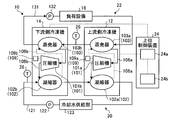
- FIG. 1 is a block diagram showing a schematic configuration of the refrigerator system.
- FIG. 2 is an explanatory diagram showing a schematic configuration of the refrigerator shown in FIG.
- FIG. 3 is a graph showing the relationship between the combination of refrigerators in the refrigerator system and power consumption.
- FIG. 4 is a flowchart showing an example of the processing operation of the refrigerator system.
- FIG. 5 is a graph showing the relationship between the equipment load factor and the power consumption.
- FIG. 6 is a flowchart showing an example of the processing operation of the refrigerator system.
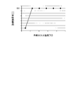
- FIG. 7 is a graph showing the relationship between the first threshold value, the equipment load factor, and the cooling water inlet temperature.
- FIG. 8 is a graph showing the relationship among refrigerator combinations, equipment load factor, and power consumption.
- FIG. 1 is a block diagram showing a schematic configuration of the refrigerator system.
- FIG. 2 is an explanatory diagram showing a schematic configuration of the refrigerator shown in FIG.
- FIG. 3 is a graph showing the relationship between the combination of refrigerators in the refrigerator
- FIG. 9 is a flowchart showing an example of the processing operation of the refrigerator system.
- FIG. 10 is an explanatory diagram for explaining control of the load factor of the refrigerator.
- FIG. 11 is a graph showing the relationship among the load factor of the refrigerator, the equipment load factor, and the power consumption.
- FIG. 12 is a flowchart illustrating an example of the processing operation of the refrigerator system.
- FIG. 13 is an explanatory diagram for explaining control of the load factor of the refrigerator.
- FIG. 14 is a graph showing the relationship among the load factor of the refrigerator, the equipment load factor, and the power consumption.
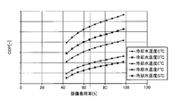
- FIG. 15 is a graph showing the relationship between the equipment load factor and the COP.
- FIG. 16 is a flowchart illustrating an example of the processing operation of the refrigerator system.
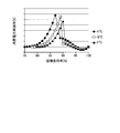
- FIG. 17 is a graph showing the relationship between the power consumption reduction rate and the equipment load factor.
- FIG. 1 is a block diagram illustrating a schematic configuration of the refrigerator system 10.
- the refrigerator system 10 includes an upstream refrigerator 12, a downstream refrigerator 14, a cooling water circulation system 20, a cold water circulation system 22, a host controller 24, a cold water intermediate temperature detection unit 26, and an inlet cooling water temperature. And a detection unit 28.
- Cold water is supplied to the load facility 18 by the refrigerator system 10.
- the upstream refrigerator 12 cools the cold water supplied to the load facility 18.
- the upstream refrigerator 12 cools cold water using a refrigerant.
- the upstream refrigerator 12 evaporates the first compressor 101a that compresses the refrigerant, the first condenser 102a that condenses the refrigerant compressed by the first compressor 101a, and the refrigerant condensed by the first condenser 102a.
- a first evaporator 103a that cools the cold water and a first circulation path 106a.
- the first compressor 101a, the first condenser 102a, and the first evaporator 103a are connected via a first circulation path 106a.
- the refrigerant of the upstream refrigerator 12 circulates through the first compressor 101a, the first condenser 102a, and the first evaporator 103a via the first circulation path 106a.
- the control device 109a controls the operation of each unit.
- the downstream refrigerator 14 cools the cold water supplied to the load facility 18.
- the downstream refrigerator 14 cools cold water using a refrigerant.
- the downstream refrigerator 14 evaporates the second compressor 101b that compresses the refrigerant, the second condenser 102b that condenses the refrigerant compressed by the second compressor 101b, and the refrigerant condensed by the second condenser 102b.
- the second evaporator 103b that cools the cold water that has passed through the first evaporator 103a, and the second circulation path 106b.
- the second compressor 101b, the second condenser 102b, and the second evaporator 103b are connected via the second circulation path 106b.
- the refrigerant of the downstream refrigerator 14 circulates through the second compressor 101b, the second condenser 102b, and the second evaporator 103b via the second circulation path 106b.
- the control device 109b controls the operation of each unit.
- the load facility 18 is an air conditioning facility installed in a building such as a building or a factory.
- the load facility 18 uses the cold water supplied from the upstream refrigerator 12 and the downstream refrigerator 14 to cool the object.
- the load facility 18 exchanges heat between the supplied cold water and air, and supplies the air cooled with the cold water to the building. Thereby, the temperature or humidity of the building is adjusted.
- the load facility 18 may be a refrigeration facility or a refrigeration facility. Further, the load facility 18 may exchange heat between the supplied cold water and the liquid, and supply the liquid cooled with the cold water to the object.
- the cooling water circulation system 20 supplies cooling water to the upstream refrigerator 12 and the downstream refrigerator 14 to cool the refrigerant of the upstream refrigerator 12 and the refrigerant of the downstream refrigerator 14.
- the cooling water cools the refrigerant flowing through the first condenser 102 a of the upstream side cooler 12 and the refrigerant flowing through the second condenser 102 b of the downstream side refrigerator 14.
- the second condenser 102b performs heat exchange between the cooling water supplied from the cooling water supply unit 123 and the refrigerant, and cools the refrigerant of the downstream refrigerator 14.
- the first condenser 102a performs heat exchange between the cooling water that has passed through the second condenser 102b and the refrigerant, and cools the refrigerant of the upstream refrigerator 12.
- the cooling water circulation system 20 includes a cooling water pipe 121, a pump 122, and a cooling water supply unit 123.
- the cooling water pipe 121 is a pipe line through which cooling water flows.
- the pump 122 is arrange
- the cooling water supply unit 123 supplies the cooling water to the cooling water pipe 121 and collects the cooling water heat-exchanged with the refrigerant.
- the cooling water pipe 121 is connected to each of the first condenser 102 a of the upstream refrigerator 12, the second condenser 102 b of the downstream refrigerator 14, the pump 122, and the cooling water supply unit 123.
- the cooling water circulates through the first condenser 102 a, the second condenser 102 b, and the cooling water supply unit 123 through the cooling water pipe 121 by the operation of the pump 122.
- the cooling water supplied from the cooling water supply unit 123 flows through the second condenser 102 b, flows through the first condenser 102 a, and then returns to the cooling water supply unit 123. Thereby, the refrigerant flowing through the second condenser 102b and the refrigerant flowing through the first condenser 102a are cooled by the cooling water.
- the cold water circulation system 22 supplies cold water cooled by the refrigerant of the upstream refrigerator 12 and the refrigerant of the downstream refrigerator 14 to the load facility 18.
- the cold water circulation system 22 supplies the cold water heat-exchanged with the air in the load facility 18 to the upstream refrigerator 12 and the downstream refrigerator 14.
- the cold water circulation system 22 includes a cold water pipe 131 and a pump 132.
- the cold water piping 131 is a pipeline through which cold water flows.
- the pump 132 is arrange
- the cold water pipe 131 is connected to each of the first evaporator 103 a of the upstream refrigerator 12, the second evaporator 103 b of the downstream refrigerator 14, the pump 132, and the load facility 18.
- the cold water circulates through the first evaporator 103a, the second evaporator 103b, and the load facility 18 via the cold water pipe 131 by the operation of the pump 132.
- the cold water subjected to heat exchange in the load facility 18 flows through the first evaporator 103 a, flows through the second evaporator 103 b, and is then supplied to the load facility 18.
- the cold water is cooled by the first evaporator 103a and the second evaporator 103b, and then supplied to the load facility 18.
- the host control device 24 has a calculation unit including a processor such as a CPU and a storage unit including a memory such as a ROM or a RAM.
- the host controller 24 controls the operation and stop of the upstream refrigerator 12 and the downstream refrigerator 14 and the load (or load factor) of the upstream refrigerator 12 and the downstream refrigerator 14.
- the host control device 24 includes an operating number determination unit 24a and a load distribution determination unit 24b.
- the operating number determination unit 24 a Based on the equipment load factor required for the load equipment 18, the operating number determination unit 24 a, of the two refrigerators of the upstream side refrigerator 12 and the downstream side refrigerator 14, is operated (operated). Determine the number.
- the load distribution determination unit 24b sets the load factor or load of the refrigerator that is operated (operated).
- the load factor is the current load ratio when the rated load is 100%. When the load factor is 0%, the target refrigerator is stopped.
- the load is a real number of the output of the refrigerator.
- the load distribution determination unit 24b sets the load factor or load of the refrigerator to be operated (operated) based on the required load of the load facility.
- the load distribution determination unit 24b adjusts the loads on the upstream refrigerator 12 and the downstream refrigerator 14 based on the operating state of the upstream refrigerator 12 and the downstream refrigerator 14, and the state of cold water and cooling water. To do.
- the load distribution determination unit 24b is configured so that, based on the detection result of the cold water intermediate temperature detection unit 26, the upstream refrigerator 12 and the downstream refrigerator 14 have the set load factor. The load factor or load of 12 and the load factor or load of the downstream refrigerator 14 are adjusted.
- the cold water intermediate temperature detection unit 26 detects the temperature of the cold water flowing through the cold water pipe 131.
- the cold water intermediate temperature detection unit 26 detects the temperature of the cold water in the cold water pipe 131 between the first evaporator 103a and the second evaporator 103b.
- the cold water intermediate temperature detection unit 26 detects the temperature of the cold water supplied to the second evaporator 103b.
- the inlet cooling water temperature detector 28 detects the temperature of the cooling water flowing through the cooling water pipe 121.
- the inlet cooling water temperature detection unit 28 detects the temperature of the cooling water supplied to the second condenser 102b at the inlet of the second condenser 102b.
- FIG. 2 is a diagram showing a schematic configuration of the upstream refrigerator 12 according to the present embodiment. Since the downstream refrigerator 14 has the same structure as the upstream refrigerator 12, the description thereof is omitted.
- the first compressor 101a, the first condenser 102a, the first evaporator 103a, the first circulation path 106a, and the control device 109a are respectively referred to as the compressor 101, the condenser 102, the evaporator 103, and the circulation path. 106 and controller 109.
- the upstream refrigerator 12 includes a compressor 101, a condenser 102, an evaporator 103, an intermediate cooler 104, and a control device 109.
- the compressor 101 and the condenser 102 are connected via a refrigerant pipe 136a.
- the condenser 102 and the evaporator 103 are connected via a refrigerant pipe 136b.
- the evaporator 103 and the compressor 101 are connected via a refrigerant pipe 136c.
- the intermediate cooler 104 is disposed in the refrigerant pipe 136b.
- the refrigerant flows through the refrigerant pipes 136a, 136b, and 136c.
- the circulation path 106 includes refrigerant pipes 136a, 136b, and 136c.
- the compressor 101, the condenser 102, the evaporator 103, and the intercooler 104 are connected via a circulation path 106 including refrigerant pipes 136a, 136b, and 136c.
- the refrigerant circulates through the compressor 101, the condenser 102, the evaporator 103, and the intercooler 104 via the circulation path 106.
- the upstream refrigerator 12 is provided in an expansion valve (high-stage expansion valve) 107 provided in the refrigerant pipe 136 b on the upstream side of the intermediate cooler 104 and in a refrigerant pipe 136 b on the downstream side of the intermediate cooler 104. And an expansion valve (low stage expansion valve) 108.
- Compressor 101 is a turbo compressor that compresses refrigerant by rotation of an impeller.
- the compressor 101 includes an electric motor 111 and a compression unit 112 including an impeller driven by the electric motor 111.
- the electric motor 111 is capable of changing the number of revolutions per unit time by inverter control, and a variable speed machine that rotates the compression unit 112 at the changed number of revolutions, and a fixed speed machine that rotates the compression unit 112 at a constant number of revolutions. including.
- the compression unit 112 may be a two-stage compression type compression unit provided with two impellers coaxially rotated by the electric motor 111 or a single-stage compression type compression unit provided with one impeller rotated by the electric motor 111. But you can.
- the compression unit 112 is a two-stage compression system, the gas-phase refrigerant supplied from the evaporator 103 to the compressor 101 is compressed by the first stage impeller and then further compressed by the second stage impeller. Then, the pressure and temperature are increased and supplied to the condenser 102 via the refrigerant pipe 136a.
- the gas-phase refrigerant supplied from the evaporator 103 to the compressor 101 is compressed by the impeller and then increased in pressure and temperature via the refrigerant pipe 136a. It is supplied to the condenser 102.
- the condenser 102 is connected to a cooling water pipe 121 to which cooling water is supplied.
- the gas-phase refrigerant supplied from the compressor 101 to the condenser 102 is condensed and liquefied by exchanging heat with the cooling water supplied to the cooling water pipe 121.
- the liquefied liquid phase refrigerant is supplied to the evaporator 103 via the refrigerant pipe 136b.
- the evaporator 103 is connected to a cold water pipe 131 to which cold water is supplied.
- the liquid-phase refrigerant supplied from the condenser 102 to the evaporator 103 evaporates by exchanging heat with the cold water supplied to the cold water pipe 131.
- the temperature of the cold water decreases due to heat exchange between the cold water and the refrigerant.
- the liquid-phase refrigerant exchanged with cold water evaporates and vaporizes.
- the vaporized refrigerant in the vapor phase is supplied to the compressor 101 via the refrigerant pipe 136c.
- the intermediate cooler 104 separates the refrigerant that has been liquefied in the condenser 102 and then passed through the expansion valve 107 into a liquid phase and a gas phase.
- the intercooler 104 maintains a constant pressure difference between the condenser 102 and the evaporator 103 and vaporizes a part of the liquid phase refrigerant.
- the intercooler 104 is supplied with a gas-phase refrigerant and a liquid-phase refrigerant that have not been fully condensed in the condenser 102.
- the intercooler 104 functions as a gas-liquid separator that separates the supplied gas-phase refrigerant and liquid-phase refrigerant.
- the gas phase refrigerant separated by the intercooler 104 is supplied to the compressor 101.
- the liquid phase refrigerant separated by the intercooler 104 is supplied to the expansion valve 108.
- the refrigerant that has passed through the expansion valve 108 is supplied to the evaporator 103.
- the expansion valve (high stage expansion valve) 107 expands the refrigerant liquefied by the condenser 102.
- the expansion valve 107 reduces the refrigerant from the condensation pressure to the intermediate pressure.
- the refrigerant decompressed by the expansion valve 107 is supplied to the intermediate cooler 104.
- the expansion valve (low stage expansion valve) 108 expands the liquid refrigerant (saturated liquid refrigerant) that has passed through the intercooler 104.
- the expansion valve 108 reduces the refrigerant from the intermediate pressure to the evaporation pressure.
- the refrigerant decompressed by the expansion valve 108 is supplied to the evaporator 103.
- the control device 109 is based on an instruction input from the host control device 24, and the upstream refrigerator 12 including the compressor 101, the condenser 102, the evaporator 103, the intercooler 104, the expansion valve 107, and the expansion valve 108.
- the control device 109 of the upstream refrigerator 12 sets the upstream refrigerator so that the upstream refrigerator 12 has a load factor set by the host controller 24 based on the detection result of the cold water intermediate temperature detection unit 26. Adjust the operation of the machine 12.
- the host control device 24 sends “downstream distributed load / (cold water flow rate ⁇ specific heat) + water supply temperature set value” to the control device 109 of the upstream refrigerator 12 as the target temperature of the intermediate water supply temperature.
- the control device 109 of the upstream refrigerator 12 controls the operation of the upstream refrigerator 12 so that the intermediate water supply temperature becomes the target temperature.
- the control device 109 of the downstream refrigerator 14 controls the operation of each part of the downstream refrigerator 14 based on an instruction input from the host controller 24.
- FIG. 3 is a graph showing the relationship between the combination of refrigerators in the refrigerator system 10 and power consumption.
- the first compressor 101a of the upstream refrigerator 12 is a variable speed machine and the second compressor 101b of the downstream refrigerator 14 is a fixed speed machine
- the first compressor 101a is fixed.
- the power consumption of the refrigerator system 10 is higher than that in the case where the second compressor 101b is a fixed speed machine and the first compressor 101a is a fixed speed machine and the second compressor 101b is a variable speed machine. Is suppressed.
- the refrigerator system 10 uses the first compressor 101a of the upstream refrigerator 12 as a variable speed machine and the second compressor 101b of the downstream refrigerator 14 as a fixed speed machine, that is, one of the refrigerators.
- the apparatus cost is higher than when the first compressor 101a of the upstream refrigerator 12 is a variable speed machine and the second compressor 101b of the downstream refrigerator 14 is a variable speed machine. Is also suppressed.
- the first compressor 101a of the upstream refrigerator 12 is a variable speed machine
- the second compressor 101b of the downstream refrigerator 14 is a fixed speed machine. preferable. Therefore, the power consumption of the refrigerator system 10 can be suppressed while suppressing an increase in apparatus cost.
- the water supply temperature of the upstream refrigerator 12 is higher than the water supply temperature of the downstream refrigerator 14.
- the rated capacity of the upstream refrigerator 12 is higher than the rated capacity of the downstream refrigerator 14. Therefore, when the equipment load is distributed to the upstream refrigerator 12 and the downstream refrigerator 14, the load factor of the upstream refrigerator 12 is smaller than that of the downstream refrigerator 14. For this reason, when the equipment load is equally distributed to each of the upstream refrigerator 12 and the downstream refrigerator 14, the upstream refrigerator 12 has a low load factor, and the downstream refrigerator 14 has a high load factor.
- a variable speed refrigerator having excellent partial load characteristics (a compressor having a variable speed compressor) is installed as the upstream refrigerator 12, and a fixed speed machine having excellent rated load efficiency is installed.
- the efficiency of each of the upstream side refrigerator 12 and the downstream side refrigerator 14 is improved by installing the refrigerator (the refrigerator having a variable speed compressor) as the downstream side refrigerator 14.
- FIG. 4 is a flowchart illustrating an example of the processing operation of the refrigerator system 10.
- FIG. 5 is a graph showing the relationship between the equipment load factor and the power consumption.
- FIG. 6 is a flowchart illustrating an example of the processing operation of the refrigerator system 10.
- FIG. 7 is a graph showing the relationship between the first threshold value, the equipment load factor, and the cooling water inlet temperature.
- FIG. 8 is a graph showing the relationship among refrigerator combinations, equipment load factor, and power consumption.
- FIG. 9 is a flowchart showing an example of the processing operation of the refrigerator system 10.
- FIG. 10 is an explanatory diagram for explaining control of the load factor of the refrigerator.
- FIG. 10 is an explanatory diagram for explaining control of the load factor of the refrigerator.
- FIGS. 4 to 11 are a graph showing the relationship among the load factor of the refrigerator, the equipment load factor, and the power consumption.
- the examples shown in FIGS. 4 to 11 are preferably used when the first compressor 101a of the upstream refrigerator 12 is a variable speed machine and the second compressor 101b of the downstream refrigerator 14 is a fixed speed machine. This is an example of processing that can be performed.
- FIG. 4 shows processing from the start of the operation when the refrigerator system 10 is stopped until the operation is stopped.
- the host control device 24 sets the first mode in which the upstream refrigerator 12 is operated and the downstream refrigerator 14 is stopped.
- the host control device 24 sets the second mode in which both the upstream refrigerator 12 and the downstream refrigerator 14 are operated.
- the equipment load factor is the load factor of the entire refrigerator system 10. When the load factor of both the two refrigerators is 100%, the equipment load factor is also 100%.
- the host controller 24 When the equipment load factor becomes lower than the first threshold value, the host controller 24 starts from the second mode in which both the upstream refrigerator 12 and the downstream refrigerator 14 are operated, and the upstream refrigerator 12 is operated downstream. Switch to the first mode in which the side refrigerator 14 stops. When the equipment load factor becomes higher than the second threshold, the host controller 24 operates the upstream refrigerator 12 and the downstream refrigerator from the first mode in which the upstream refrigerator 12 is operated and the downstream refrigerator 14 is stopped. Switch to the second mode in which both of the machines 14 are operated. The second threshold value is higher than the first threshold value.
- the operation of the refrigerator system 10 is started (step S12).
- the host controller 24 operates the upstream refrigerator 12 (step S14).
- the host control device 24 sends an operation instruction to the control device 109 of the upstream refrigerator 12.
- the control device 109 of the upstream refrigerator 12 operates each part of the upstream refrigerator 12 based on an instruction input from the host controller 24.
- the host control device 24 maintains the state of the first mode in which the upstream refrigerator 12 is operated and the downstream refrigerator 14 is stopped during the period after the start of operation with a low load.
- the host controller 24 changes the load at the set change rate, and the present load factor is changed to the required load factor of the load facility 18. Get close to.
- the host controller 24 determines whether the equipment load factor is equal to or higher than the second threshold in the first mode in which the upstream refrigerator 12 is operated and the downstream refrigerator 14 is stopped (step S16). When the host controller 24 determines that the equipment load factor is not equal to or greater than the second threshold (No in step S16), that is, the equipment load factor is less than the second threshold, the process proceeds to step S24.
- Step S18 the host controller 24 is set to the second mode in which both the upstream refrigerator 12 and the downstream refrigerator 14 are operated.
- the host control device 24 sends an operation instruction to the control device 109 of the downstream refrigerator 14.
- the control device 109 of the downstream refrigerator 14 operates each part of the downstream refrigerator 14 based on an instruction input from the host controller 24.
- the host control device 24 determines whether the equipment load factor is less than the first threshold in a state where both the upstream refrigerator 12 and the downstream refrigerator 14 are operating (step S20). If the host controller 24 determines that the equipment load factor is not less than the first threshold (No in step S20), that is, the equipment load factor is equal to or greater than the first threshold, the process returns to step S20.
- the downstream controller 14 stops the downstream refrigerator 14 (Step S20). S22). That is, the host control device 24 sets the first mode in which the upstream refrigerator 12 is operated and the downstream refrigerator 14 is stopped.
- step S24 it is determined whether or not to stop the operation. If the host controller 24 determines that the operation is not stopped (No in Step S24), the host controller 24 returns to Step S16 and performs the process of Step S16. When it is determined that the operation is to be stopped (Yes in Step S24), the upper control device 24 stops the upstream refrigerator 12 (Step S26) and ends the process.
- the host control device 24 can prevent the occurrence of hunting due to the dead zone by providing the first threshold value and the second threshold value and switching the number of operating refrigerators. Further, as shown in FIG. 5, when the variable speed refrigerator and the fixed speed refrigerator are compared, the variable speed refrigerator consumes less power under the same equipment load.
- FIG. 5 shows a case where the cooling water inlet temperature is A ° C. and B ° C. A ° C. and B ° C. indicate that B ° C. is higher than A ° C., that is, A ⁇ B. Therefore, when operating one refrigerator, it can drive
- any one of the refrigerators is operated.
- the downstream refrigerator 14 of the variable speed machine it is possible to operate with less power consumption.
- the host controller 24 preferably adjusts the first threshold and the second threshold based on the coolant inlet temperature detected by the inlet coolant temperature detector 28.
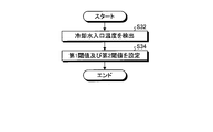
- the host control device 24 detects the cooling water inlet temperature by the inlet cooling water temperature detection unit 28 (step S32), and sets the first threshold value and the second threshold value based on the detected temperature. (Step S34).
- the host controller 24 stores the relationship between the cooling water inlet temperature and the equipment load factor (threshold) as shown in FIG. 7, and sets the first threshold value and the second threshold value based on the cooling water inlet temperature. To do.
- the first threshold value and the second threshold value increase as the cooling water inlet temperature increases. That is, the first threshold value and the second threshold value have a lower equipment load factor as the temperature detected by the cooling water temperature detection unit 28 is lower.
- FIG. 8 shows the power consumption and the equipment load factor when the cooling water inlet temperature is C ° C., D ° C., E ° C., F ° C., G ° C. and H ° C. Showing the relationship. C ° C, D ° C, E ° C, F ° C, G ° C, and H ° C increase in this order, that is, C ⁇ D ⁇ E ⁇ F ⁇ G ⁇ H. As shown in FIG. 8, less power is consumed in the state of operation with two units (variable speed + fixed speed operation) than in the case of operation with one unit (operation of one variable speed unit). The equipment load factor becomes higher as the temperature becomes higher.
- the first threshold value and the second threshold value are different from the state of operating with one unit (variable speed machine + fixed speed machine operation) than the state of operating with one unit (variable speed machine one unit operation). Even if it sets so that the equipment load factor that power consumption may decrease may be pinched
- the host controller 24 When switching from the state where one refrigerator operates to the state where two refrigerators operate, that is, when the equipment load factor exceeds the second threshold value in the first mode, the host controller 24 The operation of the side refrigerator 14 is started and the second mode is set (step S42).
- the host controller 24 enters the state of the second mode in which both the upstream refrigerator 12 and the downstream refrigerator 14 are operated, the host controller 24 operates with equal load distribution (step S44). That is, when the equipment load factor exceeds the second threshold value in the first mode and the operation in the second mode is started in the first mode, the host control device 24 equalizes the loads on the upstream refrigerator 12 and the downstream refrigerator 14. And The host control device 24 operates by making the load on the upstream refrigerator 12 equal to the load on the downstream refrigerator 14.
- the host control device 24 determines whether the equipment load factor is equal to or greater than the third threshold value in a state where the operation is performed with equal load distribution (step S46).
- the third threshold value is higher than the second threshold value.
- the host control device 24 determines that the equipment load factor is not equal to or greater than the third threshold value (No in step S46), the host control device 24 proceeds to step S54. If the host controller 24 determines that the equipment load factor is equal to or greater than the third threshold value (Yes in step S46), the load factor of the upstream refrigerator 12 is variable by setting the load factor of the downstream refrigerator 14 to 100%. (Step S48). That is, when the host controller 24 operates in the second mode and the equipment load factor exceeds a third threshold value that is higher than the second threshold value, the load factor of the downstream refrigerator 14 is set to 100%, and the equipment load factor is The load factor of the upstream refrigerator 12 is changed according to the rate. The host controller 24 sets the downstream refrigerator 14 to a constant load (rated load) and changes the load factor of the upstream refrigerator 12 according to the equipment load factor.
- step S50 Whether the load factor (equipment load factor) is equal to or lower than the third threshold in the state where the load factor of the downstream refrigerator 14 is set to 100% and the load factor of the upstream refrigerator 12 is variably set. Is determined (step S50). If the host controller 24 determines that the load factor is not less than or equal to the third threshold (No in step S50), that is, the load factor is higher than the third threshold, the process returns to step S48.
- Step S52 When the host controller 24 determines that the load factor is equal to or less than the third threshold (Yes in Step S50), the host controller 24 operates with equal load distribution (Step S52).
- the host control device 24 determines whether or not the load factor is less than the first threshold in a state where the operation is performed with equal load distribution (step S54). If the host controller 24 determines that the load factor is not less than the first threshold (No in step S54), the host controller 24 returns to step S46.
- the host controller 24 stops the downstream refrigerator 14 (Step S56).
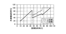
- the host control device 24 operates by changing the load factor of each refrigerator as the equipment load factor increases as shown in FIG. 10 by performing the processing shown in FIG.
- the host control device 24 operates the upstream refrigerator 12 by one when the equipment load factor is low. In this state, when the equipment load factor is equal to or higher than the second threshold, the operation of the downstream refrigerator 14 is also started. When operation with two units is started, operation is performed with an equally distributed load. Since the 100% load of the upstream refrigerator 12 and the downstream refrigerator 14 is different, different load factors are obtained when the same load is distributed. In FIG. 10, the load factor of the downstream refrigerator 14 is higher than the load factor of the upstream refrigerator 12. When the equipment load factor is equal to or greater than the third threshold, the host controller 24 adjusts the load factor of the upstream refrigerator 12 with the load factor of the downstream refrigerator 14 set to 100%.
- FIG. 11 shows a result of measurement in the case where the load of the upstream refrigerator 12 and the load of the downstream refrigerator 14 are set to be equal load ratios and equal load distribution. Further, FIG. 11 shows the measurement results when the load of the upstream refrigerator 12 that is a variable speed machine is variable and the load of the downstream refrigerator 14 that is a fixed speed machine is a rated load. Further, FIG.
- the upstream refrigerator 12 shows the results of measurement in the case where the load of 12 is a load where the difference with respect to the equal load is + ⁇ % and the load of the downstream refrigerator 14 is the load where the difference with respect to the equal load is ⁇ %.
- the relationship between ⁇ %, 10%, and ⁇ % is ⁇ ⁇ 10 ⁇ .
- the host controller 24 determines the difference between the upstream refrigerator 12 and the downstream refrigerator 14 with respect to the equal load.
- the load between the upstream refrigerator 12 and the downstream refrigerator 14 is a load that is within 10%, that is, the load of the upstream refrigerator 12 and the downstream refrigerator 14 is an equal load.
- the compressor uses the downstream refrigerator 14) of the fixed speed machine as the rated load, and distributes the remaining load to the upstream refrigerator 12 of the variable speed machine (the first compressor is the upstream refrigerator 12 of the variable speed machine). As compared with the case, power consumption can be reduced and operation can be performed efficiently.
- FIG. 12 is a flowchart illustrating an example of the processing operation of the refrigerator system 10.
- FIG. 13 is an explanatory diagram for explaining control of the load factor of the refrigerator.
- FIG. 14 is a graph showing the relationship among the load factor of the refrigerator, the equipment load factor, and the power consumption.
- FIG. 15 is a graph showing the relationship between the equipment load factor and the COP.
- FIG. 15 shows the relationship between the equipment load factor and the COP when the cooling water inlet temperature is C ° C, D ° C, E ° C, F ° C, and G ° C.
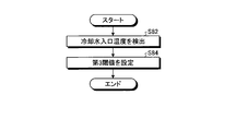
- FIG. 16 is a flowchart illustrating an example of the processing operation of the refrigerator system 10.
- FIG. 17 is a graph showing the relationship between the power consumption reduction rate and the equipment load factor.
- the first compressor 101a of the upstream refrigerator 12 is a fixed speed machine
- the second compressor 101b of the downstream refrigerator 14 is a fixed speed machine
- the host control device 24 sets the first mode in which the upstream refrigerator 12 is operated and the downstream refrigerator 14 is stopped. As shown in FIG. 12, when the equipment load factor exceeds the second threshold value in the first mode, the host controller 24 starts the operation of the downstream refrigerator 14 and sets the second mode (step S62). That is, the host controller 24 operates in the first mode in which the upstream refrigerator 12 is operated and the downstream refrigerator 14 is stopped, and the equipment load factor becomes equal to or higher than the second threshold value that is higher than the first threshold value. The second mode in which both the upstream refrigerator 12 and the downstream refrigerator 14 are operated.
- the host controller 24 When the host control device 24 enters the state of the second mode in which both the upstream refrigerator 12 and the downstream refrigerator 14 are operated, the host controller 24 operates with equal load distribution (step S64). That is, when the equipment load factor exceeds the second threshold value in the first mode and the operation in the second mode is started in the first mode, the host control device 24 equalizes the loads on the upstream refrigerator 12 and the downstream refrigerator 14. And
- the host control device 24 determines whether the equipment load factor is equal to or greater than the third threshold value in a state where the operation is performed with equal load distribution (step S66).
- the third threshold value is higher than the second threshold value.
- Step S68 the load factor of the upstream refrigerator 12 is variable while the load factor of the downstream refrigerator 14 is set to a constant load. That is, when the host controller 24 is operating both the upstream refrigerator 12 and the downstream refrigerator 14 and the facility load factor exceeds a third threshold value that is higher than the second threshold value, In response to the increase in the load factor, the load factor of the upstream refrigerator 12 is increased while keeping the load of the downstream refrigerator 14 constant. The host controller 24 sets the downstream refrigerator 14 to a constant load (rated load) and changes the load factor of the upstream refrigerator 12 according to the equipment load factor.
- the host controller 24 determines whether the load factor of the upstream refrigerator 12 has reached 100% with the load factor of the downstream refrigerator 14 set to a constant load and the load factor of the upstream refrigerator 12 variably set. Is determined (step S70). If the host controller 24 determines that the load factor of the upstream refrigerator 12 is not 100% (No in Step S70), the host controller 24 returns to Step S68.
- step S70 When the host controller 24 determines that the load factor of the upstream refrigerator 12 has reached 100% (Yes in step S70), the host controller 24 sets the load of the downstream refrigerator 14 variably (step S72). The host controller 24 varies the load factor of the downstream refrigerator 14.
- the host control device 24 determines whether or not the load factor of the downstream refrigerator 14 is equal to or less than a certain load (step S74). When it determines with the load factor of the downstream refrigerator 14 being below a fixed load (it is Yes at step S74), it returns to step S68. When it determines with the load factor of the downstream refrigerator 14 not being below a fixed load (it is No at step S74), it returns to step S74.
- step S66 when the host controller 24 determines that the equipment load factor is not equal to or greater than the third threshold (No in step S66), the process proceeds to step S76.
- the host controller 24 determines whether or not the equipment load factor is less than the first threshold value in the second mode in which both the upstream refrigerator 12 and the downstream refrigerator 14 are operating (step S76). ).
- Step S76 when it is determined that the equipment load factor has become lower than the first threshold (Yes in Step S76), the host control device 24 stops the downstream refrigerator 14 and enters the first mode (Step S76). S78). In Step S76, when it is determined that the equipment load factor is not less than the first threshold (No in Step S76), the host control device 24 returns to Step S66.
- the host control device 24 operates by changing the load factor of each refrigerator as the equipment load factor increases as shown in FIG. 13 by performing the processing shown in FIG.
- the host control device 24 operates the upstream refrigerator 12 by one when the equipment load factor is low. In this state, when the equipment load factor is equal to or higher than the second threshold, the operation of the downstream refrigerator 14 is also started. When operation with two units is started, operation is performed with an equally distributed load. Since the 100% load of the upstream refrigerator 12 and the downstream refrigerator 14 is equal, when the same load is distributed, the load factor is equal. When the equipment load factor is equal to or greater than the third threshold (80% or greater in the example shown in FIG. 13), the host controller 24 adjusts the load factor of the downstream refrigerator 14 by changing the load factor of the downstream refrigerator 14. To do.
- FIG. 14 shows a result of measurement in the case where the load of the upstream refrigerator 12 and the load of the downstream refrigerator 14 are set to be equal load ratio, and the case of equal load distribution (load equal distribution). Further, FIG. 14 shows the measurement result when the load on the downstream refrigerator 14 is set as the rated load and the remaining load is distributed to the load on the upstream refrigerator 12. Further, FIG. 14
- the load on the upstream refrigerator 12 is a load where the difference with respect to the equal load is + a%
- the load on the downstream refrigerator 14 is the load where the difference with respect to the equal load is ⁇ a%.
- the upstream side refrigerator When the load on the upstream side refrigerator 12 is a load where the difference with respect to the equal load is + b%, and the load on the downstream side refrigerator 14 is a load where the difference with respect to the equal load is ⁇ b%, the upstream side refrigerator When the load of 12 is a load where the difference with respect to the equal load is + c%, and the load of the downstream refrigerator 14 is a load where the difference with respect to the equal load is ⁇ c%, the load of the upstream refrigerator 12 is The measurement results are shown for the case where the difference with respect to the equal load is + d% and the load of the downstream refrigerator 14 is the load with the difference with respect to the equal load being ⁇ d%.
- the relationship between a%, b%, c%, and d% is a
- the power consumption can be suppressed by allocating the load to the upstream refrigerator 12 as much as possible when the equipment load exceeds a predetermined threshold.
- the equipment load factor falls below the third threshold (80% in the example shown in FIG. 15)
- the change in COP with respect to the refrigerator load factor becomes non-linear, and the efficiency decreases with respect to the change in refrigerator load factor. Therefore, until the two refrigerators reach the third threshold value, the efficiency can be improved by increasing the loads of both refrigerators with equal load distribution.
- the COP change is smaller than the third threshold value, the efficiency can be improved by bringing the more efficient upstream refrigerator 12 closer to the rated load first.
- the host controller 24 adjusts the third threshold value based on the cooling water inlet temperature detected by the inlet cooling water temperature detector 28. As shown in FIG. 16, the host controller 24 detects the coolant inlet temperature by the inlet coolant temperature detector 28 (step S82), and sets the third threshold based on the detected temperature (step S84). . The host controller 24 stores the relationship between the cooling water inlet temperature and the equipment load factor, and sets the third threshold value based on the cooling water inlet temperature. The third threshold value decreases as the cooling water inlet temperature increases. That is, the third threshold value is a lower equipment load factor as the temperature detected by the cooling water temperature detection unit 28 is higher.
- FIG. 17 shows the equipment load factor and the power consumption reduction rate when the first compressor 101a of the upstream refrigerator 12 is a fixed speed machine and the second compressor 101b of the downstream refrigerator 14 is a fixed speed machine. It is a figure which shows the relationship.
- FIG. 17 shows the relationship between the equipment load factor and the power consumption reduction rate when the cooling water inlet temperature is F ° C, G ° C, or H ° C.
- F ° C, G ° C, and H ° C increase in this order, that is, F ⁇ G ⁇ H.
- Whether to change the load distribution ratio from the equal load ratio distribution to the upstream residual load and the downstream load limit is determined according to the cooling water inlet temperature.
- the load distribution ratio is changed when the cooling water inlet temperature is higher.
- the power consumption reduction rate is low, so operation is performed with only equal load factor distribution. As shown in FIG. 17, the equipment load factor becomes lower as the cooling water inlet temperature detected by the inlet cooling water temperature detector 28 is higher.
Landscapes
- Engineering & Computer Science (AREA)
- Physics & Mathematics (AREA)
- Mechanical Engineering (AREA)
- Thermal Sciences (AREA)
- General Engineering & Computer Science (AREA)
- Other Air-Conditioning Systems (AREA)
- Air Conditioning Control Device (AREA)
Abstract
冷凍機を効率良く運転できる冷凍機システムを提供すること。冷凍機システムは、冷媒を圧縮する第1圧縮機、第1圧縮機により圧縮された冷媒を凝縮させる第1凝縮器、及び第1凝縮器により凝縮された冷媒を蒸発させて冷水を冷却する第1蒸発器を有する上流側冷凍機と、冷媒を圧縮する第2圧縮機、第2圧縮機により圧縮された冷媒を凝縮させる第2凝縮器、及び第2凝縮器により凝縮された冷媒を蒸発させて第1蒸発器を通過した冷水を冷却する第2蒸発器を有する下流側冷凍機と、上流側冷凍機及び下流側冷凍機の運転を制御する上位制御装置と、を有する。第1圧縮機は可変速機であり、第2圧縮機は、固定速機である。
Description
本発明は、2台の冷凍機を備える冷凍機システムに関する。
冷凍機を有する冷凍機システムは、建物の空調設備、冷蔵設備、及び冷凍設備のような負荷設備に使用される。冷凍機システムにおいて、冷凍サイクルを構成する2台の冷凍機が直列で接続され、負荷設備に供給される冷水が2台の冷凍機の凝縮器によって冷却される冷凍機システムが知られている。特許文献1には、上流側冷凍機(上流側熱源機)を通過し、下流側冷凍機(下流側熱源機)に流入する冷媒(熱媒)の温度である中間温度を制御対象として、運転コストが所定値以下となるように中間温度を設定する技術が開示されている。
冷凍機システムにおいて、冷凍機が効率良く運転されることにより、エネルギー消費の低減が図られる。本発明は上述した課題を解決するものであり、冷凍機を効率良く運転できる冷凍機システムを提供することを目的とする。
上述の目的を達成するために、本発明の冷凍機システムは、冷媒を圧縮する第1圧縮機、前記第1圧縮機により圧縮された冷媒を凝縮させる第1凝縮器、及び前記第1凝縮器により凝縮された冷媒を蒸発させ、冷水を冷却する第1蒸発器を有する上流側冷凍機と、冷媒を圧縮する第2圧縮機、前記第2圧縮機により圧縮された冷媒を凝縮させる第2凝縮器、及び前記第2凝縮器により凝縮された冷媒を蒸発させ、前記第1蒸発器を通過した冷水を冷却する第2蒸発器を有する下流側冷凍機と、前記上流側冷凍機及び前記下流側冷凍機の稼動、停止及び、前記上流側冷凍機及び前記下流側冷凍機の負荷を制御する上位制御装置と、を有し、前記第1圧縮機は、可変速機であり、前記第2圧縮機は、固定速機であることを特徴とする。
前記上位制御装置は、設備負荷率が第1閾値よりも小さい場合、前記上流側冷凍機を運転し、前記下流側冷凍機を停止する第1モードとし、前記上流側冷凍機を運転し、前記下流側冷凍機を停止している状態で、設備負荷率が前記第1閾値よりも高い第2閾値以上となった場合、前記上流側冷凍機及び前記下流側冷凍機の両方を運転する第2モードとし、前記上流側冷凍機及び前記下流側冷凍機の両方を運転している状態で、設備負荷率が前記第1閾値よりも低くなった場合、前記第1モードとすることが好ましい。
前記上位制御装置は、前記第1モードで設備負荷率が前記第2閾値を超え、前記第2モードでの運転を開始する場合、前記上流側冷凍機と前記下流側冷凍機との負荷を等負荷に対する差が10%以内となる負荷とすることが好ましい。
前記上位制御装置は、前記第1モードで設備負荷率が前記第2閾値を超え、前記第2モードでの運転を開始する場合、前記上流側冷凍機と前記下流側冷凍機との負荷を等負荷とすることが好ましい。
前記上位制御装置は、前記第2モードで運転し、かつ、設備負荷率が第2閾値よりも高い第3閾値を超えた場合、前記下流側冷凍機の負荷率を100%とし、設備負荷率に応じて前記上流側冷凍機の負荷率を変動させることが好ましい。
前記第2凝縮器は、供給される冷却水と冷媒との間で熱交換を行い、前記冷媒を冷却し、前記第1凝縮器は、前記第2凝縮器を通過した冷却水と冷媒との間で熱交換を行い、前記冷媒を冷却し、前記第2凝縮器に供給される冷却水の温度を検出する冷却水温度検出部を有し、前記上位制御装置は、前記冷却水温度検出部が検出した温度に基づいて、前記第1閾値を調整することが好ましい。
前記第1閾値は、前記冷却水温度検出部が検出した温度が低いほど低い設備負荷率となることが好ましい。
上述の目的を達成するために、本発明の冷凍機システムは、冷媒を圧縮する第1圧縮機、前記第1圧縮機により圧縮された冷媒を凝縮させる第1凝縮器、及び前記第1凝縮器により凝縮された冷媒を蒸発させ、冷水を冷却する第1蒸発器を有する上流側冷凍機と、冷媒を圧縮する第2圧縮機、前記第2圧縮機により圧縮された冷媒を凝縮させる第2凝縮器、及び前記第2凝縮器により凝縮された冷媒を蒸発させ、前記第1蒸発器を通過した冷水を冷却する第2蒸発器を有する下流側冷凍機と、前記上流側冷凍機及び前記下流側冷凍機の稼動、停止及び、前記上流側冷凍機及び前記下流側冷凍機の負荷を制御する上位制御装置と、を有し、前記第1圧縮機は、固定速機であり、前記第2圧縮機は、固定速機であり、前記上位制御装置は、設備負荷率が第1閾値よりも小さい場合、前記上流側冷凍機を運転し、前記下流側冷凍機を停止する第1モードとし、前記上流側冷凍機を運転し、前記下流側冷凍機を停止している状態で、設備負荷率が前記第1閾値よりも高い第2閾値以上となった場合、前記上流側冷凍機及び前記下流側冷凍機の両方を運転する第2モードとし、前記上流側冷凍機及び前記下流側冷凍機の両方を運転している状態で、設備負荷率が前記第1閾値よりも低くなった場合、前記第1モードとすることを特徴とする。
前記上流側冷凍機及び前記下流側冷凍機の両方を運転している状態で、かつ、設備負荷率が第2閾値よりも高い第3閾値を超えた場合、設備負荷率の上昇に対応して、前記下流側冷凍機の負荷を一定にしたまま、前記上流側冷凍機の負荷率を上昇させ、前記上流側冷凍機の負荷率が100%になった後、前記下流側冷凍機の負荷率を変動させることが好ましい。
前記第2凝縮器は、供給される冷却水と冷媒との間で熱交換を行い、前記冷媒を冷却し、前記第1凝縮器は、前記第2凝縮器を通過した冷却水と冷媒との間で熱交換を行い、前記冷媒を冷却し、前記第2凝縮器に供給される冷却水の温度を検出する冷却水温度検出部を有し、前記上位制御装置は、前記冷却水温度検出部が検出した温度に基づいて、前記第3閾値を調整することが好ましい。
前記第3閾値は、前記冷却水温度検出部が検出した温度が高いほど低い設備負荷率となることが好ましい。
本発明によれば、冷凍機を効率良く運転できる冷凍機システムが提供される。
以下、この発明につき図面を参照しつつ詳細に説明する。なお、この実施例により本発明が限定されるものではなく、また、実施例が複数ある場合には、各実施例を組み合わせて構成するものも含むものである。また、下記実施例における構成要素には、当業者が容易に想定できるもの、あるいは実質的に同一のものが含まれる。
[第1実施形態]
図1は、冷凍機システム10の概略構成を示すブロック図である。冷凍機システム10は、上流側冷凍機12と、下流側冷凍機14と、冷却水循環系20と、冷水循環系22と、上位制御装置24と、冷水中間温度検出部26と、入口冷却水温度検出部28と、を備える。冷凍機システム10により、負荷設備18に冷水が供給される。
図1は、冷凍機システム10の概略構成を示すブロック図である。冷凍機システム10は、上流側冷凍機12と、下流側冷凍機14と、冷却水循環系20と、冷水循環系22と、上位制御装置24と、冷水中間温度検出部26と、入口冷却水温度検出部28と、を備える。冷凍機システム10により、負荷設備18に冷水が供給される。
上流側冷凍機12は、負荷設備18に供給される冷水を冷却する。上流側冷凍機12は、冷媒を使って冷水を冷却する。上流側冷凍機12は、冷媒を圧縮する第1圧縮機101aと、第1圧縮機101aにより圧縮された冷媒を凝縮させる第1凝縮器102aと、第1凝縮器102aにより凝縮された冷媒を蒸発させて冷水を冷却する第1蒸発器103aと、第1循環経路106aと、を有する。第1圧縮機101aと第1凝縮器102aと第1蒸発器103aとは、第1循環経路106aを介して接続される。上流側冷凍機12の冷媒は、第1循環経路106aを介して、第1圧縮機101a、第1凝縮器102a、及び第1蒸発器103aを循環する。上流側冷凍機12は、制御装置109aが各部の動作を制御する。
下流側冷凍機14は、負荷設備18に供給される冷水を冷却する。下流側冷凍機14は、冷媒を使って冷水を冷却する。下流側冷凍機14は、冷媒を圧縮する第2圧縮機101bと、第2圧縮機101bにより圧縮された冷媒を凝縮させる第2凝縮器102bと、第2凝縮器102bにより凝縮された冷媒を蒸発させて第1蒸発器103aを通過した冷水を冷却する第2蒸発器103bと、第2循環経路106bと、を有する。第2圧縮機101bと第2凝縮器102bと第2蒸発器103bとは、第2循環経路106bを介して接続される。下流側冷凍機14の冷媒は、第2循環経路106bを介して、第2圧縮機101b、第2凝縮器102b、及び第2蒸発器103bを循環する。下流側冷凍機14は、制御装置109bが各部の動作を制御する。
負荷設備18は、例えばビル又は工場のような建物に設置される空調設備である。負荷設備18は、上流側冷凍機12及び下流側冷凍機14から供給された冷水を使って、対象物を冷却する。例えば、負荷設備18は、供給された冷水と空気とを熱交換し、冷水で冷却された空気を建物に供給する。これにより、建物の温度又は湿度が調整される。
なお、負荷設備18は、冷蔵設備でもよいし、冷凍設備でもよい。また、負荷設備18は、供給された冷水と液体とを熱交換し、冷水で冷却された液体を対象物に供給してもよい。
冷却水循環系20は、上流側冷凍機12及び下流側冷凍機14に冷却水を供給して、上流側冷凍機12の冷媒及び下流側冷凍機14の冷媒を冷却する。冷却水は、上流側冷却機12の第1凝縮器102aを流れる冷媒、及び下流側冷凍機14の第2凝縮器102bを流れる冷媒を冷却する。
第2凝縮器102bは、冷却水供給部123から供給される冷却水と冷媒との間で熱交換を行って、下流側冷凍機14の冷媒を冷却する。第1凝縮器102aは、第2凝縮器102bを通過した冷却水と冷媒との間で熱交換を行って、上流側冷凍機12の冷媒を冷却する。
冷却水循環系20は、冷却水配管121と、ポンプ122と、冷却水供給部123とを有する。冷却水配管121は、冷却水が流れる管路である。ポンプ122は、冷却水供給部123と第2凝縮器102bとの間の冷却水配管121に配置される。冷却水供給部123は、冷却水配管121に冷却水を供給し、冷媒と熱交換した冷却水を回収する。
冷却水配管121は、上流側冷凍機12の第1凝縮器102a、下流側冷凍機14の第2凝縮器102b、ポンプ122、及び冷却水供給部123のそれぞれと接続される。冷却水は、ポンプ122の作動により、冷却水配管121を介して、第1凝縮器102a、第2凝縮器102b、及び冷却水供給部123を循環する。
冷却水循環系20において、冷却水供給部123から供給された冷却水は、第2凝縮器102bを流れ、第1凝縮器102aを流れた後、冷却水供給部123に戻る。これにより、第2凝縮器102bを流れる冷媒及び第1凝縮器102aを流れる冷媒が、冷却水で冷却される。
冷水循環系22は、上流側冷凍機12の冷媒及び下流側冷凍機14の冷媒で冷却された冷水を負荷設備18に供給する。また、冷水循環系22は、負荷設備18で空気と熱交換した冷水を上流側冷凍機12及び下流側冷凍機14に供給する。
冷水循環系22は、冷水配管131と、ポンプ132とを有する。冷水配管131は、冷水が流れる管路である。ポンプ132は、負荷設備18と第2蒸発器103bとの間の冷水配管131に配置される。
冷水配管131は、上流側冷凍機12の第1蒸発器103a、下流側冷凍機14の第2蒸発器103b、ポンプ132、及び負荷設備18のそれぞれと接続される。冷水は、ポンプ132の作動により、冷水配管131を介して、第1蒸発器103a、第2蒸発器103b、及び負荷設備18を循環する。
冷水循環系22において、負荷設備18で熱交換された冷水は、第1蒸発器103aを流れ、第2蒸発器103bを流れた後、負荷設備18に供給される。冷水は、第1蒸発器103a及び第2蒸発器103bで冷却された後、負荷設備18に供給される。
上位制御装置24は、CPUのようなプロセッサを含む演算部と、ROM又はRAMのようなメモリを含む記憶部とを有する。上位制御装置24は、上流側冷凍機12及び下流側冷凍機14の稼動、停止及び、上流側冷凍機12及び下流側冷凍機14の負荷(または負荷率)を制御する。上位制御装置24は、運転台数決定部24aと、負荷配分決定部24bと、を有する。
運転台数決定部24aは、負荷設備18に必要とされる設備負荷率に基づいて、上流側冷凍機12及び下流側冷凍機14の2台の冷凍機のうち、運転(稼動)する冷凍機の台数を決定する。負荷配分決定部24bは、運転(稼動)される冷凍機の負荷率又は負荷を設定する。負荷率とは、定格負荷を100%としたときの現在の負荷の割合である。負荷率が0%の場合、対象の冷凍機は停止している状態となる。また、負荷とは、冷凍機の出力の実数である。負荷配分決定部24bは、負荷設備の要求負荷に基づいて、運転(稼動)される冷凍機の負荷率又は負荷を設定する。また、負荷配分決定部24bは、上流側冷凍機12、下流側冷凍機14の運転状態や、冷水、冷却水の状態に基づいて、上流側冷凍機12と下流側冷凍機14の負荷を調整する。負荷配分決定部24bは、例えば、冷水中間温度検出部26の検出結果に基づいて、上流側冷凍機12及び下流側冷凍機14のそれぞれが設定された負荷率となるように、上流側冷凍機12の負荷率または負荷及び下流側冷凍機14の負荷率または負荷を調整する。
冷水中間温度検出部26は、冷水配管131を流れる冷水の温度を検出する。冷水中間温度検出部26は、第1蒸発器103aと第2蒸発器103bとの間の冷水配管131の冷水の温度を検出する。冷水中間温度検出部26は、第2蒸発器103bに供給される冷水の温度を検出する。
入口冷却水温度検出部28は、冷却水配管121を流れる冷却水の温度を検出する。入口冷却水温度検出部28は、第2凝縮器102bの入口において、第2凝縮器102bに供給される冷却水の温度を検出する。
図2は、本実施形態に係る上流側冷凍機12の概略構成を示す図である。下流側冷凍機14は、上流側冷凍機12と同等の構造であるため、説明を省略する。以下の説明では、第1圧縮機101a、第1凝縮器102a、第1蒸発器103a、第1循環経路106a及び制御装置109aのそれぞれを、圧縮機101、凝縮器102、蒸発器103、循環経路106及び制御装置109と称する。
図2に示すように、上流側冷凍機12は、圧縮機101と、凝縮器102と、蒸発器103と、中間冷却器104と、制御装置109と、を有する。圧縮機101と凝縮器102とは冷媒配管136aを介して接続される。凝縮器102と蒸発器103とは、冷媒配管136bを介して接続される。蒸発器103と圧縮機101とは、冷媒配管136cを介して接続される。中間冷却器104は、冷媒配管136bに配置される。冷媒は、冷媒配管136a、136b、136cを流れる。循環経路106は、冷媒配管136a、136b、136cを含む。
圧縮機101、凝縮器102、蒸発器103、及び中間冷却器104は、冷媒配管136a、136b、136cを含む循環経路106を介して接続される。冷媒は、循環経路106を介して、圧縮機101、凝縮器102、蒸発器103、及び中間冷却器104を循環する。
また、上流側冷凍機12は、中間冷却器104の上流側の冷媒配管136bに設けられた膨張弁(高段膨張弁)107と、中間冷却器104の下流側の冷媒配管136bに設けられた膨張弁(低段膨張弁)108とを有する。
圧縮機101は、羽根車の回転によって冷媒を圧縮するターボ圧縮機である。圧縮機101は、電動機111と、電動機111によって駆動される羽根車を含む圧縮部112を有する。電動機111は、インバータ制御により単位時間当たりの回転数を変更可能であり変更された回転数で圧縮部112を回転させる可変速機と、一定の回転数で圧縮部112を回転させる固定速機とを含む。
圧縮部112は、電動機111により回転する羽根車を同軸上に2つ備えた2段圧縮方式の圧縮部でもよいし、電動機111により回転する羽根車を1つ備えた単段圧縮方式の圧縮部でもよい。圧縮部112が2段圧縮方式である場合、蒸発器103から圧縮機101に供給される気相の冷媒は、1段目の羽根車で圧縮された後、2段目の羽根車でさらに圧縮され、圧力及び温度を上昇させつつ冷媒配管136aを介して凝縮器102に供給される。圧縮部112が単段圧縮方式である場合、蒸発器103から圧縮機101に供給される気相の冷媒は、羽根車で圧縮された後、圧力及び温度を上昇させつつ冷媒配管136aを介して凝縮器102に供給される。
凝縮器102は、冷却水が供給される冷却水配管121と接続される。圧縮機101から凝縮器102に供給される気相の冷媒は、冷却水配管121に供給された冷却水と熱交換して凝縮し液化する。液化された液相の冷媒は、冷媒配管136bを介して蒸発器103に供給される。
蒸発器103は、冷水が供給される冷水配管131と接続される。凝縮器102から蒸発器103に供給される液相の冷媒は、冷水配管131に供給された冷水と熱交換して蒸発する。冷水と冷媒との熱交換により、冷水の温度は低下する。冷水と熱交換した液相の冷媒は、蒸発し気化する。気化された気相の冷媒は、冷媒配管136cを介して圧縮機101に供給される。
中間冷却器104は、凝縮器102において液化された後、膨張弁107を通過した冷媒を液相と気相とに分離する。中間冷却器104は、凝縮器102と蒸発器103との間に一定の圧力差を維持し、液相の冷媒の一部を気化させる。中間冷却器104には、凝縮器102において凝縮し切れなかった気相の冷媒と液相の冷媒とが供給される。中間冷却器104は、供給された気相の冷媒と液相の冷媒とを分離する気液分離器として機能する。中間冷却器104で分離された気相の冷媒は圧縮機101に供給される。中間冷却器104で分離された液相の冷媒は膨張弁108に供給される。膨張弁108を通過した冷媒は蒸発器103に供給される。
膨張弁(高段膨張弁)107は、凝縮器102で液化された冷媒を膨張させる。膨張弁107は、冷媒を凝縮圧から中間圧まで減圧させる。膨張弁107で減圧された冷媒は、中間冷却器104に供給される。
膨張弁(低段膨張弁)108は、中間冷却器104を通過した液体の冷媒(飽和液冷媒)を膨張させる。膨張弁108は、冷媒を中間圧から蒸発圧まで減圧させる。膨張弁108で減圧された冷媒は、蒸発器103に供給される。
制御装置109は、上位制御装置24から入力される指示に基づいて、圧縮機101、凝縮器102、蒸発器103、中間冷却器104、膨張弁107、及び膨張弁108を含む上流側冷凍機12を制御する。例えば、上流側冷凍機12の制御装置109は、冷水中間温度検出部26の検出結果に基づいて、上流側冷凍機12が上位制御装置24で設定された負荷率となるように、上流側冷凍機12の運転を調整する。例えば、上位制御装置24は、「下流側配分負荷/(冷水流量×比熱)+送水温度設定値」を中間送水温度の目標温度として、上流側冷凍機12の制御装置109に送る。上流側冷凍機12の制御装置109は、中間送水温度が目標温度となるように、上流側冷凍機12の運転を制御する。下流側冷凍機14の制御装置109は、上位制御装置24から入力される指示に基づいて、下流側冷凍機14の各部の運転を制御する。
図3は、冷凍機システム10の冷凍機の組み合わせと消費電力との関係を示すグラフである。図3に示すように、上流側冷凍機12の第1圧縮機101aを可変速機とし、下流側冷凍機14の第2圧縮機101bを固定速機とした場合、第1圧縮機101aを固定速機とし第2圧縮機101bを固定速機とする場合、及び第1圧縮機101aを固定速機とし第2圧縮機101bを可変速機とする場合に比べて、冷凍機システム10の消費電力が抑制される。
また、冷凍機システム10は、上流側冷凍機12の第1圧縮機101aを可変速機とし、下流側冷凍機14の第2圧縮機101bを固定速機とすることで、つまり、一方の冷凍機を固定速機とすることで、上流側冷凍機12の第1圧縮機101aを可変速機とし、下流側冷凍機14の第2圧縮機101bを可変速機とした場合よりも、装置コストも抑制される。
以上より、本実施形態に係る冷凍機システム10において、上流側冷凍機12の第1圧縮機101aを可変速機とし、下流側冷凍機14の第2圧縮機101bを固定速機とすることが好ましい。これにより、装置コストの増加を抑制しつつ、冷凍機システム10の消費電力が抑制できる。
冷凍機システム10は、上流側冷凍機12の送水温度が下流側冷凍機14の送水温度よりも高い。上流側冷凍機12の定格能力は、下流側冷凍機14の定格能力よりも高い。そのため、設備負荷を上流側冷凍機12と下流側冷凍機14とに配分した場合、上流側冷凍機12の負荷率が下流側冷凍機14に比べて小さくなる。このため、設備負荷を上流側冷凍機12及び下流側冷凍機14のそれぞれに等配分した場合、上流側冷凍機12は低い負荷率となり、下流側冷凍機14は高い負荷率となる。
冷凍機システム10において、部分負荷特性に優れた可変速機の冷凍機(圧縮機が可変速機の冷凍機)が上流側冷凍機12として設置され、定格負荷の効率に優れた固定速機の冷凍機(圧縮機が可変速機の冷凍機)が下流側冷凍機14として設置されることで、上流側冷凍機12及び下流側冷凍機14それぞれの効率が向上する。
次に、図4から図11を用いて、冷凍機システム10の処理動作について説明する。図4は、冷凍機システム10の処理動作の一例を示すフローチャートである。図5は、設備負荷率と消費電力との関係を示すグラフである。図6は、冷凍機システム10の処理動作の一例を示すフローチャートである。図7は、第1閾値と設備負荷率と冷却水入口温度との関係を示すグラフである。図8は、冷凍機の組み合わせと設備負荷率と消費電力との関係を示すグラフである。図9は、冷凍機システム10の処理動作の一例を示すフローチャートである。図10は、冷凍機の負荷率の制御を説明するための説明図である。図11は、冷凍機の負荷率と設備負荷率と消費電力との関係を示すグラフである。図4から図11に示す例は、上流側冷凍機12の第1圧縮機101aを可変速機とし、下流側冷凍機14の第2圧縮機101bを固定速機とした場合に好適に用いることができる処理の一例である。
図4は、冷凍機システム10が停止した状態から運転を開始し、運転を停止するまでの処理を示す。上位制御装置24は、設備負荷率が低い場合、上流側冷凍機12を運転し下流側冷凍機14を停止する第1モードとする。上位制御装置24は、設備負荷率が高い場合、上流側冷凍機12及び下流側冷凍機14の両方を運転する第2モードとする。
設備負荷率は、冷凍機システム10全体の負荷率である。2台の冷凍機の両方の負荷率を100%とした場合、設備負荷率も100%となる。
上位制御装置24は、設備負荷率が第1閾値よりも低くなった場合、上流側冷凍機12及び下流側冷凍機14の両方が運転する第2モードから、上流側冷凍機12が運転し下流側冷凍機14が停止する第1モードへ切り替える。上位制御装置24は、設備負荷率が第2閾値よりも高くなった場合、上流側冷凍機12を運転し下流側冷凍機14を停止する第1モードから、上流側冷凍機12及び下流側冷凍機14の両方を運転する第2モードへ切り替える。第2閾値は、第1閾値よりも高い値である。
冷凍機システム10の運転が開始される(ステップS12)。上位制御装置24は、上流側冷凍機12を稼動させる(ステップS14)。上位制御装置24は、上流側冷凍機12の制御装置109に稼働する指示を送る。上流側冷凍機12の制御装置109は、上位制御装置24から入力される指示に基づいて、上流側冷凍機12の各部を稼動させる。上位制御装置24は、負荷が低い運転開始後の期間においては、上流側冷凍機12を運転し下流側冷凍機14を停止する第1モードの状態を維持する。上位制御装置24は、負荷設備18の要求負荷率と現状の設備負荷率とに差がある場合、設定された変化率で負荷を変化させ、現状の設備負荷率を負荷設備18の要求負荷率に近付ける。
上位制御装置24は、上流側冷凍機12を運転し下流側冷凍機14を停止する第1モードの状態で、設備負荷率が第2閾値以上であるかを判定する(ステップS16)。上位制御装置24は、設備負荷率が第2閾値以上ではない(ステップS16でNo)、すなわち、設備負荷率が第2閾値未満であると判定した場合、ステップS24に進む。
上位制御装置24は、設備負荷率が第2閾値以上である(ステップS16でYes)と判定した場合、下流側冷凍機14を稼動させる(ステップS18)。すなわち、上位制御装置24は、上流側冷凍機12及び下流側冷凍機14の両方を運転する第2モードとする。上位制御装置24は、下流側冷凍機14の制御装置109に稼働する指示を送る。下流側冷凍機14の制御装置109は、上位制御装置24から入力される指示に基づいて、下流側冷凍機14の各部を稼動させる。
上位制御装置24は、上流側冷凍機12及び下流側冷凍機14の両方が運転している状態で、設備負荷率が第1閾値未満であるかを判定する(ステップS20)。上位制御装置24は、設備負荷率が第1閾値未満ではない(ステップS20でNo)、つまり設備負荷率が第1閾値以上であると判定した場合、ステップS20に戻る。
上位制御装置24は、設備負荷率が第1閾値未満である(ステップ20でYes)、つまり設備負荷率が第1閾値よりも低くなったと判定した場合、下流側冷凍機14を停止させる(ステップS22)。すなわち、上位制御装置24は、上流側冷凍機12を運転し下流側冷凍機14を停止する第1モードとする。
上位制御装置24は、ステップS16でNoと判定した場合、または、ステップS22の処理を行った場合、つまり、上流側冷凍機12が運転し下流側冷凍機14が停止した第1モードである場合、運転停止するか否かを判定する(ステップS24)。上位制御装置24は、運転停止しない(ステップS24でNo)と判定した場合、ステップS16に戻り、ステップS16の処理を行う。上位制御装置24は、運転停止する(ステップS24でYes)と判定した場合、上流側冷凍機12を停止し(ステップS26)、処理を終了する。
上位制御装置24は、第1閾値と第2閾値を設け、冷凍機の運転台数を切り換えることで、不感帯によりハンチングが発生することを防止することができる。また、図5に示すように、可変速機の冷凍機と固定速機の冷凍機とを比較すると、可変速機の冷凍機の方が同じ設備負荷での消費電力が小さい。図5は、冷却水入口温度がA℃の場合とB℃の場合を示している。A℃とB℃とは、B℃の方がA℃よりも高い温度、つまりA<Bとなる。したがって、1台の冷凍機を運転する場合、可変速機の上流側冷凍機12を運転させることで、少ない消費電力で運転することができる。
また、上流側冷凍機12の第1圧縮機101aを固定速機とし、下流側冷凍機14の第2圧縮機101bを可変速機とした場合において、いずれか1台の冷凍機を運転させる場合、可変速機の下流側冷凍機14を運転させることで、少ない消費電力で運転することができる。
上位制御装置24は、入口冷却水温度検出部28が検出した冷却水入口温度に基づいて、第1閾値及び第2閾値を調整することが好ましい。図6に示すように、上位制御装置24は、入口冷却水温度検出部28で冷却水入口温度を検出し(ステップS32)、検出した温度に基づいて、第1閾値及び第2閾値を設定する(ステップS34)。上位制御装置24は、図7に示すような、冷却水入口温度と設備負荷率(閾値)との関係を記憶しており、冷却水入口温度に基づいて、第1閾値及び第2閾値を設定する。第1閾値及び第2閾値は、冷却水入口温度が高くなるに従って高くなる。すなわち、第1閾値及び第2閾値は、冷却水温度検出部28が検出した温度が低いほど低い設備負荷率となる。
ここで、図8は、冷却水入口温度がC℃の場合、D℃の場合、E℃の場合、F℃の場合、G℃の場合及びH℃の場合の消費電力と設備負荷率との関係を示している。C℃とD℃とE℃とF℃とG℃とH℃とは、この順で温度が高くなる、つまりC<D<E<F<G<Hとなる。図8に示すように、1台で運転している状態(可変速機1台運転)よりも2台で運転している状態(可変速機+固定速機運転)の方が消費電力が少なくなる設備負荷率は、温度が高くなるに従って高くなる。したがって、第1閾値及び第2閾値を冷却水入口温度が高くなるに従って高くすることで、効率良く運転することができる。なお、第1閾値及び第2閾値は、2台で運転している状態(可変速機+固定速機運転)の方が1台で運転している状態(可変速機1台運転)より、消費電力が少なくなる設備負荷率を挟むように設定しても、一方が重なるように設定してもよい。
次に、図9を用いて、2台の冷凍機が運転している状態の制御の一例を説明する。上位制御装置24は、1台の冷凍機が運転している状態から2台の冷凍機が運転する状態へ切り換える場合、すなわち、第1モードにおいて設備負荷率が第2閾値を超えた場合、下流側冷凍機14の運転を開始して第2モードとする(ステップS42)。上位制御装置24は、上流側冷凍機12及び下流側冷凍機14の両方を運転させる第2モードの状態となった場合、等負荷配分で運転を行う(ステップS44)。つまり、上位制御装置24は、第1モードで設備負荷率が第2閾値を超え、第2モードでの運転を開始する場合、上流側冷凍機12と下流側冷凍機14との負荷を等負荷とする。上位制御装置24は、上流側冷凍機12の負荷と下流側冷凍機14の負荷とを等しくして、運転を行う。
次に、上位制御装置24は、等負荷配分で運転を行っている状態で、設備負荷率が第3閾値以上であるかを判定する(ステップS46)。第3閾値は、第2閾値よりも高い値である。
上位制御装置24は、設備負荷率が第3閾値以上ではない(ステップS46でNo)と判定した場合、ステップS54に進む。上位制御装置24は、設備負荷率が第3閾値以上である(ステップS46でYes)と判定した場合、下流側冷凍機14の負荷率を100%とし、上流側冷凍機12の負荷率を可変に設定する(ステップS48)。つまり、上位制御装置24は、第2モードで運転し、かつ、設備負荷率が第2閾値よりも高い第3閾値を超えた場合、下流側冷凍機14の負荷率を100%とし、設備負荷率に応じて上流側冷凍機12の負荷率を変動させる。上位制御装置24は、下流側冷凍機14を一定負荷(定格負荷)として、上流側冷凍機12の負荷率を設備負荷率に応じて変化させる。
上位制御装置24は、下流側冷凍機14の負荷率を100%とし、上流側冷凍機12の負荷率を可変に設定した状態で、負荷率(設備負荷率)が第3閾値以下であるかを判定する(ステップS50)。上位制御装置24は、負荷率が第3閾値以下ではない(ステップS50でNo)、つまり負荷率が第3閾値より高いと判定した場合、ステップS48に戻る。
上位制御装置24は、負荷率が第3閾値以下である(ステップS50でYes)と判定した場合、等負荷配分で運転を行う(ステップS52)。上位制御装置24は、等負荷配分で運転を行っている状態で、負荷率が第1閾値未満であるかを判定する(ステップS54)。上位制御装置24は、負荷率が第1閾値未満ではない(ステップS54でNo)と判定した場合、ステップS46に戻る。上位制御装置24は、負荷率が第1閾値未満である(ステップS54でYes)と判定した場合、下流側冷凍機14を停止する(ステップS56)。
上位制御装置24は、図9に示す処理を行うことで図10に示すように設備負荷率が上昇するに従って、各冷凍機の負荷率を変化させて運転する。上位制御装置24は、設備負荷率が低い状態では、上流側冷凍機12を1台で運転させる。その状態で、設備負荷率が第2閾値以上となると、下流側冷凍機14の運転も開始される。2台での運転が開始されると、等配分負荷で運転される。上流側冷凍機12と下流側冷凍機14の100%の負荷が異なるため、同じ負荷を配分すると、異なる負荷率となる。図10では、下流側冷凍機14の負荷率が上流側冷凍機12の負荷率よりも高くなる。上位制御装置24は、設備負荷率が第3閾値以上となると、下流側冷凍機14の負荷率を100%とし、上流側冷凍機12の負荷率を調整する。
上位制御装置24は、1台で運転している状態である第1モードから2台で運転している状態である第2モードに切り換える際に、等負荷配分とすることで、図11に示すように、固定速機の下流側冷凍機14を定格負荷とし、可変速機の上流側冷凍機12に残りの負荷を配分するよりも消費電力を少なくすることができる。ここで、図11は、上流側冷凍機12の負荷と下流側冷凍機14の負荷を等負荷率とした場合、等負荷配分とした場合について計測した結果を示している。また、図11は、可変速機である上流側冷凍機12の負荷を可変とし、固定速機である下流側冷凍機14の負荷を定格負荷とした場合について計測した結果を示している。さらに、図11は、上流側冷凍機12の負荷を、等負荷に対する差が+α%となる負荷とし、下流側冷凍機14の負荷を、等負荷に対する差が-α%となる負荷とした場合、上流側冷凍機12の負荷を、等負荷に対する差が+10%となる負荷とし、下流側冷凍機14の負荷を、等負荷に対する差が-10%となる負荷とした場合、上流側冷凍機12の負荷を、等負荷に対する差が+β%となる負荷とし、下流側冷凍機14の負荷を、等負荷に対する差が-β%となる負荷とした場合について計測した結果を示している。α%と10%とβ%との関係は、α<10<βとなる。
上記実施形態では、1台で運転している状態である第1モードから2台で運転している状態である第2モードに切り換える際に、等配分負荷で運転したがこれに限定されない。上位制御装置24は、第1モードで設備負荷率が第2閾値を超え、第2モードでの運転を開始する場合、上流側冷凍機12と下流側冷凍機14との負荷を等負荷に対する差が10%以内となる負荷、つまり、上流側冷凍機12と下流側冷凍機14との負荷を等負荷とした場合を基準負荷として、上流側冷凍機12と下流側冷凍機14との負荷が基準負荷×0.9以上基準負荷×1.1以下となる負荷とすることで、図11の10%の場合、α%の場合で示すように、固定速機の下流側冷凍機14(第2圧縮機が固定速機の下流側冷凍機14)を定格負荷とし可変速機の上流側冷凍機12(第1圧縮機が可変速機の上流側冷凍機12)に残りの負荷を配分する場合よりも、消費電力を少なくすることができ、効率良く運転を行うことができる。
[第2実施形態]
図12は、冷凍機システム10の処理動作の一例を示すフローチャートである。図13は、冷凍機の負荷率の制御を説明するための説明図である。図14は、冷凍機の負荷率と設備負荷率と消費電力との関係を示すグラフである。図15は、設備負荷率とCOPとの関係を示すグラフである。ここで、図15は、冷却水入口温度がC℃の場合、D℃の場合、E℃の場合、F℃の場合及びG℃の場合の設備負荷率とCOPとの関係を示している。C℃とD℃とE℃とF℃とG℃とは、この順で温度が高くなる、つまりC<D<E<F<Gとなる。図16は、冷凍機システム10の処理動作の一例を示すフローチャートである。図17は、消費電力削減率と設備負荷率との関係を示すグラフである。
図12は、冷凍機システム10の処理動作の一例を示すフローチャートである。図13は、冷凍機の負荷率の制御を説明するための説明図である。図14は、冷凍機の負荷率と設備負荷率と消費電力との関係を示すグラフである。図15は、設備負荷率とCOPとの関係を示すグラフである。ここで、図15は、冷却水入口温度がC℃の場合、D℃の場合、E℃の場合、F℃の場合及びG℃の場合の設備負荷率とCOPとの関係を示している。C℃とD℃とE℃とF℃とG℃とは、この順で温度が高くなる、つまりC<D<E<F<Gとなる。図16は、冷凍機システム10の処理動作の一例を示すフローチャートである。図17は、消費電力削減率と設備負荷率との関係を示すグラフである。
本実施形態では、上流側冷凍機12の第1圧縮機101aを固定速機とし、下流側冷凍機14の第2圧縮機101bを固定速機とする。
上位制御装置24は、上流側冷凍機12を運転し、下流側冷凍機14を停止する第1モードとする。図12に示すように、上位制御装置24は、第1モードにおいて設備負荷率が第2閾値を超えた場合、下流側冷凍機14の運転を開始して第2モードとする(ステップS62)。すなわち、上位制御装置24は、上流側冷凍機12を運転し、下流側冷凍機14を停止している第1モードの状態で、設備負荷率が第1閾値よりも高い第2閾値以上となった場合、上流側冷凍機12及び下流側冷凍機14の両方を運転する第2モードとする。
上位制御装置24は、上流側冷凍機12及び下流側冷凍機14の両方を運転させる第2モードの状態となった場合、等負荷配分で運転を行う(ステップS64)。つまり、上位制御装置24は、第1モードで設備負荷率が第2閾値を超え、第2モードでの運転を開始する場合、上流側冷凍機12と下流側冷凍機14との負荷を等負荷とする。
次に、上位制御装置24は、等負荷配分で運転を行っている状態で、設備負荷率が第3閾値以上であるかを判定する(ステップS66)。第3閾値は、第2閾値よりも高い値である。
上位制御装置24は、設備負荷率が第3閾値以上である(ステップS66でYes)と判定した場合、下流側冷凍機14の負荷率を一定負荷とし、上流側冷凍機12の負荷率を可変に設定する(ステップS68)。つまり、上位制御装置24は、上流側冷凍機12及び下流側冷凍機14の両方を運転している状態で、かつ、設備負荷率が第2閾値よりも高い第3閾値を超えた場合、設備負荷率の上昇に対応して、下流側冷凍機14の負荷を一定にしたまま、上流側冷凍機12の負荷率を上昇させる。上位制御装置24は、下流側冷凍機14を一定負荷(定格負荷)として、上流側冷凍機12の負荷率を設備負荷率に応じて変化させる。
上位制御装置24は、下流側冷凍機14の負荷率を一定負荷とし、上流側冷凍機12の負荷率を可変に設定した状態で、上流側冷凍機12の負荷率が100%になったか否かを判定する(ステップS70)。上位制御装置24は、上流側冷凍機12の負荷率が100%になっていない(ステップS70でNo)と判定した場合、ステップS68に戻る。
上位制御装置24は、上流側冷凍機12の負荷率が100%になった(ステップS70でYes)と判定した場合、下流側冷凍機14の負荷を可変に設定する(ステップS72)。上位制御装置24は、下流側冷凍機14の負荷率を変動させる。
上位制御装置24は、下流側冷凍機14の負荷率が一定負荷以下か否かを判定する(ステップS74)。下流側冷凍機14の負荷率が一定負荷以下であると判定された場合(ステップS74でYes)、ステップS68に戻る。下流側冷凍機14の負荷率が一定負荷以下でないと判定された場合(ステップS74でNo)、ステップS74に戻る。
ステップS66において、上位制御装置24は、設備負荷率が第3閾値以上ではない(ステップS66でNo)と判定した場合、ステップS76に進む。上位制御装置24は、上流側冷凍機12及び下流側冷凍機14の両方を運転している第2モードの状態で、設備負荷率が第1閾値未満であるか否かを判定する(ステップS76)。
ステップS76において、設備負荷率が第1閾値よりも低くなったと判定された場合(ステップS76でYes)、上位制御装置24は、下流側冷凍機14を停止して、第1モードとする(ステップS78)。ステップS76において、設備負荷率が第1閾値未満でないと判定された場合(ステップS76でNo)、上位制御装置24は、ステップS66に戻る。
上位制御装置24は、図12に示す処理を行うことで図13に示すように設備負荷率が上昇するに従って、各冷凍機の負荷率を変化させて運転する。上位制御装置24は、設備負荷率が低い状態では、上流側冷凍機12を1台で運転させる。その状態で、設備負荷率が第2閾値以上となると、下流側冷凍機14の運転も開始される。2台での運転が開始されると、等配分負荷で運転される。上流側冷凍機12と下流側冷凍機14の100%の負荷が等しいため、同じ負荷を配分した場合、等しい負荷率となる。上位制御装置24は、設備負荷率が第3閾値以上(図13に示す例では80%以上)となると、下流側冷凍機14の負荷率を可変とし、下流側冷凍機14の負荷率を調整する。
上位制御装置24は、冷凍機が1台で運転している状態である第1モードから2台で運転している状態である第2モードに切り換える際に、等負荷配分とすることで、図14に示すように、下流側冷凍機14を定格負荷とし、上流側冷凍機12に残りの負荷を配分するよりも消費電力を少なくすることができる。ここで、図14は、上流側冷凍機12の負荷と下流側冷凍機14の負荷を等負荷率とした場合、等負荷配分(負荷等配分)とした場合について計測した結果を示している。また、図14は、下流側冷凍機14の負荷を定格負荷とし、上流側冷凍機12の負荷に残りの負荷を分配した場合について計測した結果を示している。さらに、図14は、上流側冷凍機12の負荷を、等負荷に対する差が+a%となる負荷とし、下流側冷凍機14の負荷を、等負荷に対する差が-a%となる負荷とした場合、上流側冷凍機12の負荷を、等負荷に対する差が+b%となる負荷とし、下流側冷凍機14の負荷を、等負荷に対する差が-b%となる負荷とした場合、上流側冷凍機12の負荷を、等負荷に対する差が+c%となる負荷とし、下流側冷凍機14の負荷を、等負荷に対する差が-c%となる負荷とした場合、上流側冷凍機12の負荷を、等負荷に対する差が+d%となる負荷とし、下流側冷凍機14の負荷を、等負荷に対する差が-d%となる負荷とした場合、について、計測した結果を示している。a%とb%とc%とd%との関係は、a<b<c<dとなる。
また、2台の冷凍機が共に固定速機の場合、所定の閾値以上の設備負荷になった場合、上流側冷凍機12へできるだけ負荷を配分することで、消費電力を抑えることができる。図15に示すように、設備負荷率が第3閾値(図15に示す例では80%)を下回ると、冷凍機負荷率に対するCOPの変化が非線形となり、冷凍機負荷率の変化に対する効率の低下が大きくなるため、2台の冷凍機が第3閾値に到達するまでは、両方の冷凍機の負荷を等負荷配分で上昇させることで、効率を向上させることができる。また、COPの変化が小さくなる第3閾値以上では、より効率のよい上流側冷凍機12を先に定格負荷に近づけることで、効率を向上させることができる。
上位制御装置24は、入口冷却水温度検出部28が検出した冷却水入口温度に基づいて、第3閾値を調整することが好ましい。図16に示すように、上位制御装置24は、入口冷却水温度検出部28で冷却水入口温度を検出し(ステップS82)、検出した温度に基づいて、第3閾値を設定する(ステップS84)。上位制御装置24は、冷却水入口温度と設備負荷率との関係を記憶しており、冷却水入口温度に基づいて、第3閾値を設定する。第3閾値は、冷却水入口温度が高くなるに従って低くなる。すなわち、第3閾値は、冷却水温度検出部28が検出した温度が高いほど低い設備負荷率となる。
図17は、上流側冷凍機12の第1圧縮機101aを固定速機とし、下流側冷凍機14の第2圧縮機101bを固定速機とした場合における、設備負荷率と消費電力削減率との関係を示す図である。ここで、図17は、冷却水入口温度がF℃の場合、G℃の場合、H℃の場合の設備負荷率と消費電力削減率との関係を示している。F℃とG℃とH℃とは、この順で温度が高くなる、つまりF<G<Hとなる。冷却水入口温度に応じて、等負荷率配分から上流側残負荷及び下流側負荷制限に負荷配分割合を変更するか否かを決定する。冷却水入口温度が高いほど、消費電力削減効果が高いため、冷却水入口温度が高い場合は、負荷配分割合を変更する。冷却水入口温度が低い場合は消費電力削減率が低いため、等負荷率配分のみで運転する。図17に示すように、設備負荷率は、入口冷却水温度検出部28が検出した冷却水入口温度が高いほど低い値となる。
10 冷凍機システム
12 上流側冷凍機
14 下流側冷凍機
18 負荷設備
20 冷却水循環系
22 冷水循環系
24 上位制御装置
24a 運転台数決定部
24b 負荷配分決定部
26 冷水中間温度検出部
28 入口冷却水温度検出部
101 圧縮機
101a 第1圧縮機
101b 第2圧縮機
102 凝縮器
102a 第1凝縮器
102b 第2凝縮器
103 蒸発器
103a 第1蒸発器
103b 第2蒸発器
104 中間冷却器
106 循環経路
106a 第1循環経路
106b 第2循環経路
107 膨張弁
108 膨張弁
109 制御装置
111 電動機
112 圧縮部
121 冷却水配管
122 ポンプ
123 冷却水供給部
131 冷水配管
132 ポンプ
136a 冷媒配管
136b 冷媒配管
136c 冷媒配管
12 上流側冷凍機
14 下流側冷凍機
18 負荷設備
20 冷却水循環系
22 冷水循環系
24 上位制御装置
24a 運転台数決定部
24b 負荷配分決定部
26 冷水中間温度検出部
28 入口冷却水温度検出部
101 圧縮機
101a 第1圧縮機
101b 第2圧縮機
102 凝縮器
102a 第1凝縮器
102b 第2凝縮器
103 蒸発器
103a 第1蒸発器
103b 第2蒸発器
104 中間冷却器
106 循環経路
106a 第1循環経路
106b 第2循環経路
107 膨張弁
108 膨張弁
109 制御装置
111 電動機
112 圧縮部
121 冷却水配管
122 ポンプ
123 冷却水供給部
131 冷水配管
132 ポンプ
136a 冷媒配管
136b 冷媒配管
136c 冷媒配管
Claims (11)
- 冷媒を圧縮する第1圧縮機、前記第1圧縮機により圧縮された冷媒を凝縮させる第1凝縮器、及び前記第1凝縮器により凝縮された冷媒を蒸発させて冷水を冷却する第1蒸発器を有する上流側冷凍機と、
冷媒を圧縮する第2圧縮機、前記第2圧縮機により圧縮された冷媒を凝縮させる第2凝縮器、及び前記第2凝縮器により凝縮された冷媒を蒸発させて前記第1蒸発器を通過した冷水を冷却する第2蒸発器を有する下流側冷凍機と、
前記上流側冷凍機及び前記下流側冷凍機の稼動、停止及び、前記上流側冷凍機及び前記下流側冷凍機の負荷を制御する上位制御装置と、を有し、
前記第1圧縮機は、可変速機であり、
前記第2圧縮機は、固定速機であることを特徴とする冷凍機システム。 - 前記上位制御装置は、設備負荷率が第1閾値よりも小さい場合、前記上流側冷凍機を運転し、前記下流側冷凍機を停止する第1モードとし、
前記上流側冷凍機を運転し、前記下流側冷凍機を停止している状態で、設備負荷率が前記第1閾値よりも高い第2閾値以上となった場合、前記上流側冷凍機及び前記下流側冷凍機の両方を運転する第2モードとし、
前記上流側冷凍機及び前記下流側冷凍機の両方を運転している状態で、設備負荷率が前記第1閾値よりも低くなった場合、前記第1モードとすることを特徴とする請求項1に記載の冷凍機システム。 - 前記上位制御装置は、前記第1モードで設備負荷率が前記第2閾値を超え、前記第2モードでの運転を開始する場合、前記上流側冷凍機と前記下流側冷凍機との負荷を等負荷に対する差が10%以内となる負荷とすることを特徴とする請求項2に記載の冷凍機システム。
- 前記上位制御装置は、前記第1モードで設備負荷率が前記第2閾値を超え、前記第2モードでの運転を開始する場合、前記上流側冷凍機と前記下流側冷凍機との負荷を等負荷とすることを特徴とする請求項2に記載の冷凍機システム。
- 前記上位制御装置は、前記第2モードで運転し、かつ、設備負荷率が第2閾値よりも高い第3閾値を超えた場合、前記下流側冷凍機の負荷率を100%とし、設備負荷率に応じて前記上流側冷凍機の負荷率を変動させることを特徴とする請求項2から4のいずれか一項に記載の冷凍機システム。
- 前記第2凝縮器は、供給される冷却水と冷媒との間で熱交換を行い、前記冷媒を冷却し、
前記第1凝縮器は、前記第2凝縮器を通過した冷却水と冷媒との間で熱交換を行い、前記冷媒を冷却し、
前記第2凝縮器に供給される冷却水の温度を検出する冷却水温度検出部を有し、
前記上位制御装置は、前記冷却水温度検出部が検出した温度に基づいて、前記第1閾値を調整することを特徴とする請求項2から5のいずれか一項に記載の冷凍機システム。 - 前記第1閾値は、前記冷却水温度検出部が検出した温度が低いほど低い設備負荷率となることを特徴とする請求項6に記載の冷凍機システム。
- 冷媒を圧縮する第1圧縮機、前記第1圧縮機により圧縮された冷媒を凝縮させる第1凝縮器、及び前記第1凝縮器により凝縮された冷媒を蒸発させて冷水を冷却する第1蒸発器を有する上流側冷凍機と、
冷媒を圧縮する第2圧縮機、前記第2圧縮機により圧縮された冷媒を凝縮させる第2凝縮器、及び前記第2凝縮器により凝縮された冷媒を蒸発させて前記第1蒸発器を通過した冷水を冷却する第2蒸発器を有する下流側冷凍機と、
前記上流側冷凍機及び前記下流側冷凍機の稼動、停止及び、前記上流側冷凍機及び前記下流側冷凍機の負荷を制御する上位制御装置と、を有し、
前記第1圧縮機は、固定速機であり、
前記第2圧縮機は、固定速機であり、
前記上位制御装置は、設備負荷率が第1閾値よりも小さい場合、前記上流側冷凍機を運転し、前記下流側冷凍機を停止する第1モードとし、
前記上流側冷凍機を運転し、前記下流側冷凍機を停止している状態で、設備負荷率が前記第1閾値よりも高い第2閾値以上となった場合、前記上流側冷凍機及び前記下流側冷凍機の両方を運転する第2モードとし、
前記上流側冷凍機及び前記下流側冷凍機の両方を運転している状態で、設備負荷率が前記第1閾値よりも低くなった場合、前記第1モードとすることを特徴とする冷凍機システム。 - 前記上流側冷凍機及び前記下流側冷凍機の両方を運転している状態で、かつ、設備負荷率が第2閾値よりも高い第3閾値を超えた場合、設備負荷率の上昇に対応して、前記下流側冷凍機の負荷を一定にしたまま、前記上流側冷凍機の負荷率を上昇させ、前記上流側冷凍機の負荷率が100%になった後、前記下流側冷凍機の負荷率を変動させることを特徴とする請求項8に記載の冷凍機システム。
- 前記第2凝縮器は、供給される冷却水と冷媒との間で熱交換を行い、前記冷媒を冷却し、
前記第1凝縮器は、前記第2凝縮器を通過した冷却水と冷媒との間で熱交換を行い、前記冷媒を冷却し、
前記第2凝縮器に供給される冷却水の温度を検出する冷却水温度検出部を有し、
前記上位制御装置は、前記冷却水温度検出部が検出した温度に基づいて、前記第3閾値を調整することを特徴とする請求項9に記載の冷凍機システム。 - 前記第3閾値は、前記冷却水温度検出部が検出した温度が高いほど低い設備負荷率となることを特徴とする請求項10に記載の冷凍機システム。
Priority Applications (2)
| Application Number | Priority Date | Filing Date | Title |
|---|---|---|---|
| CN201680035315.7A CN107735625B (zh) | 2015-07-31 | 2016-04-21 | 制冷机系统 |
| US15/736,559 US11221166B2 (en) | 2015-07-31 | 2016-04-21 | Refrigerator system |
Applications Claiming Priority (2)
| Application Number | Priority Date | Filing Date | Title |
|---|---|---|---|
| JP2015152177A JP6399979B2 (ja) | 2015-07-31 | 2015-07-31 | 冷凍機システム |
| JP2015-152177 | 2015-07-31 |
Publications (1)
| Publication Number | Publication Date |
|---|---|
| WO2017022282A1 true WO2017022282A1 (ja) | 2017-02-09 |
Family
ID=57942707
Family Applications (1)
| Application Number | Title | Priority Date | Filing Date |
|---|---|---|---|
| PCT/JP2016/062645 Ceased WO2017022282A1 (ja) | 2015-07-31 | 2016-04-21 | 冷凍機システム |
Country Status (4)
| Country | Link |
|---|---|
| US (1) | US11221166B2 (ja) |
| JP (1) | JP6399979B2 (ja) |
| CN (1) | CN107735625B (ja) |
| WO (1) | WO2017022282A1 (ja) |
Cited By (1)
| Publication number | Priority date | Publication date | Assignee | Title |
|---|---|---|---|---|
| WO2018180774A1 (ja) * | 2017-03-27 | 2018-10-04 | 三菱重工サーマルシステムズ株式会社 | 冷凍システムおよび冷凍システムの制御方法 |
Families Citing this family (6)
| Publication number | Priority date | Publication date | Assignee | Title |
|---|---|---|---|---|
| DE102018127175A1 (de) * | 2018-10-31 | 2020-04-30 | Klaus Scherrieble | System und Verfahren zur Regelung und Überwachung der Kälteerzeugung für eine Einheit |
| US11920836B2 (en) * | 2022-04-18 | 2024-03-05 | Fbd Partnership, L.P. | Sealed, self-cleaning, food dispensing system with advanced refrigeration features |
| WO2023209868A1 (ja) * | 2022-04-27 | 2023-11-02 | 三菱電機株式会社 | ヒートポンプ装置及び給湯システム |
| US20250216127A1 (en) * | 2023-12-29 | 2025-07-03 | Trane International Inc. | Cooling-heating units with prioritized loading, system thereof, and method thereof |
| JP2025177956A (ja) * | 2024-05-24 | 2025-12-05 | 三菱重工サーマルシステムズ株式会社 | 冷凍機の制御装置、冷凍機システム、冷凍機の制御方法、及びプログラム |
| KR102783794B1 (ko) * | 2024-06-21 | 2025-03-21 | (주)본씨앤아이 | R744 냉매를 사용하는 반도체 설비용 냉각 시스템 |
Citations (4)
| Publication number | Priority date | Publication date | Assignee | Title |
|---|---|---|---|---|
| JPH0593550A (ja) * | 1991-04-11 | 1993-04-16 | Ebara Corp | 冷凍システム |
| JP2010071639A (ja) * | 2008-08-22 | 2010-04-02 | Daikin Ind Ltd | 冷凍装置 |
| JP2012141098A (ja) * | 2010-12-28 | 2012-07-26 | Mitsubishi Heavy Ind Ltd | 熱源システムおよびその制御方法 |
| WO2014050213A1 (ja) * | 2012-09-27 | 2014-04-03 | 三菱重工業株式会社 | 熱源システム及びその制御方法 |
Family Cites Families (8)
| Publication number | Priority date | Publication date | Assignee | Title |
|---|---|---|---|---|
| AU2003211676A1 (en) * | 2002-02-28 | 2003-10-20 | Kefang You | Improvement for multi-coupled heat pump system |
| EP1548377B1 (en) | 2003-12-24 | 2013-10-23 | Sanyo Electric Co., Ltd. | Refrigerating machine having refrigerant/water heat exchanger |
| US7287395B2 (en) * | 2004-03-15 | 2007-10-30 | Emerson Climate Technologies, Inc. | Distributed cooling system |
| ATE494516T1 (de) * | 2007-05-10 | 2011-01-15 | Carrier Corp | Kühlsystem und verfahren zur steuerung von kompressoranlagen in solch einem kühlsystem |
| JP2010054186A (ja) * | 2008-07-31 | 2010-03-11 | Daikin Ind Ltd | 冷凍装置 |
| JP2011153734A (ja) * | 2010-01-26 | 2011-08-11 | Mitsubishi Heavy Ind Ltd | 冷凍機遠隔監視システムおよび冷凍機遠隔監視方法 |
| JP5511578B2 (ja) * | 2010-08-06 | 2014-06-04 | 三菱重工業株式会社 | 冷凍機制御装置 |
| EP2710314A1 (en) * | 2011-05-16 | 2014-03-26 | Carrier Corporation | Multi-compressor refrigeration system |
-
2015
- 2015-07-31 JP JP2015152177A patent/JP6399979B2/ja active Active
-
2016
- 2016-04-21 US US15/736,559 patent/US11221166B2/en active Active
- 2016-04-21 WO PCT/JP2016/062645 patent/WO2017022282A1/ja not_active Ceased
- 2016-04-21 CN CN201680035315.7A patent/CN107735625B/zh active Active
Patent Citations (4)
| Publication number | Priority date | Publication date | Assignee | Title |
|---|---|---|---|---|
| JPH0593550A (ja) * | 1991-04-11 | 1993-04-16 | Ebara Corp | 冷凍システム |
| JP2010071639A (ja) * | 2008-08-22 | 2010-04-02 | Daikin Ind Ltd | 冷凍装置 |
| JP2012141098A (ja) * | 2010-12-28 | 2012-07-26 | Mitsubishi Heavy Ind Ltd | 熱源システムおよびその制御方法 |
| WO2014050213A1 (ja) * | 2012-09-27 | 2014-04-03 | 三菱重工業株式会社 | 熱源システム及びその制御方法 |
Cited By (1)
| Publication number | Priority date | Publication date | Assignee | Title |
|---|---|---|---|---|
| WO2018180774A1 (ja) * | 2017-03-27 | 2018-10-04 | 三菱重工サーマルシステムズ株式会社 | 冷凍システムおよび冷凍システムの制御方法 |
Also Published As
| Publication number | Publication date |
|---|---|
| CN107735625B (zh) | 2020-05-08 |
| JP2017032199A (ja) | 2017-02-09 |
| JP6399979B2 (ja) | 2018-10-03 |
| CN107735625A (zh) | 2018-02-23 |
| US20180187938A1 (en) | 2018-07-05 |
| US11221166B2 (en) | 2022-01-11 |
Similar Documents
| Publication | Publication Date | Title |
|---|---|---|
| JP6399979B2 (ja) | 冷凍機システム | |
| EP2270405B1 (en) | Refrigerating device | |
| JP5639984B2 (ja) | 空気調和装置 | |
| JP5495499B2 (ja) | ターボ冷凍機および冷凍システムならびにこれらの制御方法 | |
| CN103890497A (zh) | 空气调节器及其运行方法 | |
| US10539343B2 (en) | Heat source side unit and air-conditioning apparatus | |
| JP5872052B2 (ja) | 空気調和装置 | |
| JP5984490B2 (ja) | ヒートポンプ装置 | |
| CN103348196B (zh) | 热源系统及其控制方法 | |
| JP6509047B2 (ja) | 空気調和装置 | |
| JP2012042177A (ja) | ヒートポンプ式温水発生装置 | |
| WO2016001958A1 (ja) | 空気調和装置 | |
| JPWO2015132951A1 (ja) | 冷凍装置 | |
| JP5836844B2 (ja) | 冷凍装置 | |
| JP2014173739A (ja) | 空気調和装置 | |
| JP2013113535A (ja) | 二元冷凍装置 | |
| US12480696B2 (en) | Refrigeration cycle apparatus | |
| US10317120B2 (en) | Air conditioning system with indoor and ventilation circuits | |
| WO2019078138A1 (ja) | 冷凍サイクルの制御装置、熱源装置、及びその制御方法 | |
| JP5340348B2 (ja) | 冷凍装置 | |
| EP4553411A1 (en) | Refrigeration apparatus, environment forming apparatus, and refrigeration method | |
| WO2019008660A1 (ja) | 空気調和システム | |
| JP2025083071A (ja) | 冷凍装置、環境形成装置及び冷凍方法 |
Legal Events
| Date | Code | Title | Description |
|---|---|---|---|
| 121 | Ep: the epo has been informed by wipo that ep was designated in this application |
Ref document number: 16832562 Country of ref document: EP Kind code of ref document: A1 |
|
| NENP | Non-entry into the national phase |
Ref country code: DE |
|
| 122 | Ep: pct application non-entry in european phase |
Ref document number: 16832562 Country of ref document: EP Kind code of ref document: A1 |