WO2017018292A1 - Véhicule à selle - Google Patents
Véhicule à selle Download PDFInfo
- Publication number
- WO2017018292A1 WO2017018292A1 PCT/JP2016/071249 JP2016071249W WO2017018292A1 WO 2017018292 A1 WO2017018292 A1 WO 2017018292A1 JP 2016071249 W JP2016071249 W JP 2016071249W WO 2017018292 A1 WO2017018292 A1 WO 2017018292A1
- Authority
- WO
- WIPO (PCT)
- Prior art keywords
- intake passage
- main frame
- disposed
- intake
- vehicle
- Prior art date
Links
Images


Classifications
-
- B—PERFORMING OPERATIONS; TRANSPORTING
- B62—LAND VEHICLES FOR TRAVELLING OTHERWISE THAN ON RAILS
- B62J—CYCLE SADDLES OR SEATS; AUXILIARY DEVICES OR ACCESSORIES SPECIALLY ADAPTED TO CYCLES AND NOT OTHERWISE PROVIDED FOR, e.g. ARTICLE CARRIERS OR CYCLE PROTECTORS
- B62J40/00—Arrangements of air cleaners specially adapted for cycles
- B62J40/10—Arrangements of air cleaners specially adapted for cycles characterised by air duct arrangements
-
- B—PERFORMING OPERATIONS; TRANSPORTING
- B62—LAND VEHICLES FOR TRAVELLING OTHERWISE THAN ON RAILS
- B62K—CYCLES; CYCLE FRAMES; CYCLE STEERING DEVICES; RIDER-OPERATED TERMINAL CONTROLS SPECIALLY ADAPTED FOR CYCLES; CYCLE AXLE SUSPENSIONS; CYCLE SIDE-CARS, FORECARS, OR THE LIKE
- B62K11/00—Motorcycles, engine-assisted cycles or motor scooters with one or two wheels
-
- F—MECHANICAL ENGINEERING; LIGHTING; HEATING; WEAPONS; BLASTING
- F02—COMBUSTION ENGINES; HOT-GAS OR COMBUSTION-PRODUCT ENGINE PLANTS
- F02M—SUPPLYING COMBUSTION ENGINES IN GENERAL WITH COMBUSTIBLE MIXTURES OR CONSTITUENTS THEREOF
- F02M35/00—Combustion-air cleaners, air intakes, intake silencers, or induction systems specially adapted for, or arranged on, internal-combustion engines
- F02M35/16—Combustion-air cleaners, air intakes, intake silencers, or induction systems specially adapted for, or arranged on, internal-combustion engines characterised by use in vehicles
-
- F—MECHANICAL ENGINEERING; LIGHTING; HEATING; WEAPONS; BLASTING
- F02—COMBUSTION ENGINES; HOT-GAS OR COMBUSTION-PRODUCT ENGINE PLANTS
- F02M—SUPPLYING COMBUSTION ENGINES IN GENERAL WITH COMBUSTIBLE MIXTURES OR CONSTITUENTS THEREOF
- F02M61/00—Fuel-injectors not provided for in groups F02M39/00 - F02M57/00 or F02M67/00
- F02M61/14—Arrangements of injectors with respect to engines; Mounting of injectors
Definitions
- the present invention relates to a saddle-ride type vehicle such as a motorcycle.
- the present application claims priority based on Chinese Patent Application 201510441684.3 filed on July 24, 2015, the contents of which are incorporated herein by reference.
- one main frame is connected to a head pipe that supports the front wheels in a steerable manner, and main parts such as an engine, a swing arm for rear wheel support, and a seat frame are connected to the main frame Some are supported.
- the main frame of the saddle-ride type vehicle has a rear extension extending from the head pipe to the rear of the vehicle body and a lower extension extending downward from the rear end of the rear extension. ing.
- An engine is disposed below the rear extension and at a front position of the lower extension.
- the lower end side of the downward extending portion is pivotally supported by the front end portion of the swing arm via the pivot frame, and the upper end side of the downward extending portion is coupled to a seat frame for supporting an occupant seat ing.
- an air cleaner is disposed behind the lower extending portion of the main frame, and an intake passage connecting the air cleaner and the intake portion of the engine is outside the lower extending portion of the main frame in the vehicle width direction It is known to be curved and formed to bypass the.
- the intake passage is curved and formed so as to bypass the vehicle width direction outer side of the lower extension of the main frame. For this reason, the intake amount control device and the injector provided in the intake passage protrude outward in the vehicle width direction, and the vehicle width is forced to increase.
- An object of the aspect of the present invention is to provide a saddle-ride type vehicle capable of suppressing an increase in vehicle width by suppressing an amount of protrusion of components around the intake passage to the outside in the vehicle width direction.
- a saddle-ride type vehicle includes a head pipe for supporting a front wheel in a steerable manner, a rear extension portion extending rearward from the head pipe, and a rear portion of the rear extension portion.
- a main frame having a downwardly extending portion extending downward from an end, an engine disposed below the rearward extending portion of the main frame and forwardly of the downwardly extending portion;
- the air cleaner further includes an air cleaner, a part of which is disposed behind the lower extension of the main frame, and an air intake passage connecting the air cleaner and the air intake of the engine, wherein the air intake passage
- the intake amount control device and the injector provided on the intake passage are curved so as to bypass the outer side in the vehicle width direction of the lower extending portion, and the central axis of the lower extending portion of the main frame It is disposed in front side of the.
- a seat frame for supporting an occupant's seat is attached to the main frame, and the intake air amount control device is a part of the seat frame and the lower side in plan view of the vehicle. Are arranged so as to overlap.
- the injector is provided on the inner side in the vehicle width direction of the central axis of the intake passage.
- the intake amount control device is connected to a throttle valve that adjusts the passage area in the intake passage according to the rotational position, and is connected to an operation wire to operate by the operation wire And an angle detector for detecting a rotation angle of the throttle valve, wherein the rotation operation member is an outer side in the vehicle width direction of a central axis of the intake passage.
- the angle detector is disposed on the inner side in the vehicle width direction of the central axis of the intake passage.
- a seat frame for supporting an occupant's seat is attached to the main frame, and the injector is heavy with the seat frame on the front side of the seat frame in plan view of the vehicle. It is arranged in the position where
- the intake passage is formed to be curved so as to bypass the outer side of the lower extension of the main frame in the vehicle width direction, and an intake amount control device provided on the intake passage Since the injector is disposed forward of the central axis of the downward extension of the main frame, it is possible to suppress the amount by which the intake amount control device and the injector protrude outward in the vehicle width direction. Therefore, according to the aspect of said (1), the increase in vehicle width can be suppressed.
- the intake amount control device is arranged to overlap with a part of the seat frame on the lower side in a plan view of the vehicle, to the outer side in the vehicle width direction of the intake amount control device It is possible to suppress the amount of overhang and to protect the upper side of the intake amount control device by the seat frame.
- the injector since the injector is attached to the inside in the vehicle width direction of the central axis of the intake passage, it is possible to further reduce the protrusion of the injector to the outside in the vehicle width direction.
- the rotation operation member of the intake amount control device since the rotation operation member of the intake amount control device is disposed outside the central axis of the intake passage in the vehicle width direction, it is connected to the rotation operation member or the rotation operation member Maintenance of the operation wire can be easily performed. Further, according to the above aspect (4), the angle detector of the intake amount control device is disposed inward in the vehicle width direction of the central axis of the intake passage, so the angle detector protrudes outward in the vehicle width direction. Can be suppressed.
- the injector since the injector is disposed at a position not overlapping the seat frame on the front side of the seat frame in plan view of the vehicle, the height of the occupant's seat attached to the seat frame It can be lowered.
- FIG. 1 is a left side view of a motorcycle according to an embodiment of the present invention.
- FIG. 6 is a left side view of a vehicle body frame of the motorcycle. It is a top view of the body frame of the above-mentioned motorcycle. It is the left side view which removed covers of the above-mentioned motorcycle. It is the figure which expanded and showed the A section of FIG. It is the right view which removed the covers of the above-mentioned motorcycle.
- FIG. 7 is a plan view of the above motorcycle when it is broken along the line BB in FIG. 6; It is the figure which removed the vehicle body frame of FIG. 7, and expanded a part.
- FIG. 6 is a cross-sectional view taken along the line CC of FIG. 5;
- FIG. 7 is a cross-sectional view taken along the line DD in FIG.
- FIG. 9 is a cross-sectional view taken along the line EE of FIG. 8;
- FIG. 1 is a view showing a left side surface of a motorcycle 1 which is an embodiment of a saddle-ride type vehicle according to the present embodiment.
- the front wheels 2 of the motorcycle 1 are supported by lower end portions of the left and right front forks 3.
- the left and right front forks 3 are supported by the head pipe 11 at the front end of the vehicle body frame 10 via the steering stem 4 and the top bridge 5.
- a bar-type steering handle 6 is attached to the top of the left and right front forks 3 and the top bridge 5.
- the rear wheel 7 of the motorcycle 1 is supported by the rear end of the swing arm 8.
- the front end portion of the swing arm 8 is swingably supported by the pivot portion 13 a of the vehicle body frame 10.
- the rear wheel 7 is linked to an engine 30 which is a prime mover of the motorcycle 1 via, for example, a chain type transmission mechanism.
- a lower end portion of a rear cushion 9 whose upper end portion is connected to the vehicle body frame 10 is connected to a front edge portion of the swing arm 8.
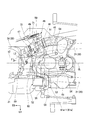
- FIG. 2 is a view of the vehicle body frame 10 as viewed from the left side
- FIG. 3 is a diagram of the vehicle body frame 10 as viewed from above.
- the body frame 10 includes the head pipe 11 described above, a single main frame 12, and a pivot frame 13.
- the head pipe 11 supports the front wheel 2 so as to be steerable via the front fork 3.
- the single main frame 12 has a front end coupled to the head pipe 11 and extends rearward and downward from the head pipe 11 along the left-right center of the vehicle body.
- the pivot frame 13 is coupled to the rear lower end of the main frame 12.
- the main frame 12 extends downward from the head pipe 11 through a curved portion 12b from a rear extension 12a extending toward the rear of the vehicle body while being slightly inclined downward and a rear end of the rear extension 12a. And a lower extending portion 12c.
- the pivot frame 13 is configured by connecting a pair of left and right plate members by a plurality of cross pipes.
- the pivot frame 13 is provided with the above-mentioned pivot portion 13 a that pivotally supports the front end portion of the swing arm 8.
- the body frame 10 also has a down frame 15 whose upper end is coupled to the head pipe 11 at a lower position on the front side of the main frame 12.
- the down frame 15 extends rearward and downward with an inclination angle larger than that of the main frame 12 to form a U-shaped space opened downward between the main frame 12 and the pivot frame 13.
- a gusset plate 16 interconnects the front edge of the main frame 12 and the upper edge of the down frame 15.
- a power unit PU in which an engine 30 and a transmission are integrated is disposed below the rear extension 12 a of the main frame 12.
- the front and rear sides of the power unit PU are fastened to the down frame 15 and the pivot frame 13 via hanger brackets (reference numeral omitted), respectively.
- the power unit PU has a built-in transmission at the rear of the crankcase 31 of the engine 30.
- the engine 30 is erected from an upper portion on the front end side of the crankcase 31 such that the cylinder portion 32 is inclined substantially along the down frame 15.
- the cylinder portion 32 is coupled to the crankcase 31 and includes a cylinder block 33 accommodating a piston (not shown) therein, and a cylinder head 34 coupled to an upper portion of the cylinder block 33 to form a combustion chamber (not shown) above the piston. And a head cover 35 covering an upper portion of the cylinder head 34.
- an intake passage 41 for introducing the air purified by the air cleaner 40 and the injected fuel is connected on the rear surface side of the cylinder head 34.
- a base end of an exhaust pipe 36 is connected to the front side of the cylinder head 34 in order to discharge the gas discharged from the combustion chamber to the outside.
- the exhaust pipe 36 is curved toward the vehicle body rear side at the front lower side of the crankcase 31 after being drawn to the front lower side from the cylinder head 34.
- An exhaust muffler 37 is connected to the rear end of the exhaust pipe 36.
- the vehicle body frame 10 includes a seat frame 20 whose front end is coupled to the main frame 12 and the pivot frame 13.
- the seat frame 20 includes a pair of left and right seat rails 21 and a pair of left and right support frames 22.
- the pair of left and right seat rails 21 has a front end portion connected to a rear end portion of the rear extension portion 12 a of the main frame 12 and extends toward the rear side of the vehicle body.
- the left and right seat rails 21 are coupled such that the front edge curves inward in the vehicle width direction, and the respective end portions are sandwiched from the left and right sides on the outer peripheral surface of the rear extension 12a.
- the pair of left and right support frames 22 is connected at the front end to the rear of the pivot portion 13 a of the pivot frame 13 and extends toward the upper rear of the vehicle body.
- the left and right support frames 22 extend beyond the rear end positions of the left and right seat rails 21.
- Rear end portions of the left and right seat rails 21 are connected to middle portions of the left and right support frames 22.
- a fuel tank 42 for storing fuel supplied to the engine 30 is disposed above the rear extension 12 a of the main frame 12. Note that only part of the fuel tank 42 may be disposed above the rear extension 12a.
- An occupant seat 43 on which a driver and a rear passenger sit is disposed behind the fuel tank 42.
- the fuel tank 42 is supported by the rear extension 12 a of the main frame 12 and the left and right seat rails 21 of the seat frame 20.
- the occupant seat 43 is supported by the left and right seat rails 21.
- the air cleaner 40 is disposed in a space surrounded by the seat rails 21 of the seat frame 20 and the support frame 22.
- the air cleaner 40 is supported by the seat rails 21 and the support frame 22, and is positioned on the rear side of the lower extension 12 c of the main frame 12.
- the whole of the air cleaner 40 is positioned on the rear side of the downward extending portion 12c, but only a portion of the air cleaner 40 may be positioned on the rear side of the downward extending portion 12c.
- Reference numeral 44 in FIG. 1 denotes a tank cover that covers the outside of the fuel tank 42, and reference numeral 45 denotes a side cover that covers the left and right sides of the vehicle.
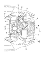
- FIG. 4 is a view showing a part of the left side surface of the motorcycle 1 from which the tank cover 44 and the side cover 45 have been removed
- FIG. 5 is an enlarged view of a portion A in FIG.
- FIG. 6 is a view showing a part of the right side surface of the motorcycle 1 from which the tank cover 44 and the side cover 45 have been removed
- 7 is a view showing a part of the upper surface of the motorcycle 1 when broken along the line B--B in FIG. 6,
- FIG. 8 is a diagram showing the vehicle body frame 10 of FIG. It is the figure which expanded and showed the part.
- the intake passage 41 connecting the air cleaner 40 and the intake portion of the engine 30 is disposed around the outside on the right side of the downward extending portion 12 c of the main frame 12.
- the rear end portion of the intake passage 41 is connected to the right side surface on the front side of the air cleaner 40, and the front end portion of the intake passage 41 is connected to the rear surface on the right side of the cylinder head 34 of the engine 30.
- the intake passage 41 whose rear end is connected to the right side surface of the air cleaner 40 slightly bulges to the right side of the vehicle body, and then the right side of the lower extension 12 c of the main frame 12 ( It is curved toward the inside in the vehicle width direction so as to bypass the outer side of one side on the left and right sides in the vehicle width direction.
- the region crossing the right side of the lower extending portion 12c bulges most outward in the vehicle width direction.
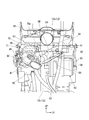
- FIG. 9 is a cross-sectional view taken along a line CC of FIG. 5, and FIG. 10 is a cross-sectional view taken along a line DD of FIG. 11 is a cross-sectional view taken along the line EE of FIG.
- an intake amount control device 46 for controlling the intake amount supplied to the combustion chamber of the engine 30, and an injector 47 for injecting fuel into the intake passage 41 at a position near the combustion chamber of the engine 30. , Is provided.
- the intake air amount control device 46 is disposed forward of the central axis L1 of the downward extending portion 12 c of the main frame 12 in the middle of the intake passage 41.
- the front side region of the lower extension 12 c of the intake passage 41 is curved inward in the vehicle width direction toward the tip end side with respect to the central axis L 1. For this reason, the intake amount control device 46 and the injector 47 which are disposed in a portion which curves inward in the vehicle width direction of the intake passage 41 are suppressed from protruding outward in the vehicle width direction.
- the intake air amount control device 46 includes a throttle body 71, an operation drum 50 (rotation operation member), a potentiometer 51 (angle detector), and an idle air control valve 70. ing.
- the throttle body 71 is interposed in the middle of the intake passage 41, and the passage area in the intake passage 41 can be adjusted by the turning operation of the throttle valve 48 disposed inside.
- the operation drum 50 (rotational operation member) is connected to the operation wire 49 and rotates the throttle valve 48 by the operation of the operation wire 49.
- the potentiometer 51 (angle detector) detects the rotation angle of the throttle valve 48.
- the idle air control valve 70 controls the area of a passage that bypasses the front and rear position of the throttle valve 48 in the intake passage 41 during idle operation.
- the operation drum 50 is disposed in the vehicle width direction outer region of the intake passage 41, and the potentiometer 51 is disposed in the vehicle width direction inner region of the intake passage 41.
- the idle air control valve 70 is disposed on the upper side of the throttle body 71.
- Reference numeral 70 a in FIG. 10 denotes a coupler of the idle air control valve 70 for connecting a feeder line or a signal line.
- the injector 47 is disposed downstream of the intake amount control device 46 of the intake passage 41 (near the intake portion of the engine 30) and atomizes the fuel supplied from the fuel tank 42 through the fuel pump 53 to form an intake passage. Inject into 41.
- the fuel pump 53 is disposed at the center of the bottom of the fuel tank 42 in the vehicle width direction.
- the fuel pump 53 and the injector 47 are connected by a fuel supply pipe 54.
- the injector 47 is disposed at an inner position in the vehicle width direction of the central axis L2 of the intake passage 41.
- the motorcycle 1 also includes a canister 52 that adsorbs the evaporated fuel in the fuel tank 42 and supplies the adsorbed fuel to the vicinity of the engine of the intake passage 41.
- the canister 52 is formed in a substantially cylindrical shape as a whole, and incorporates an adsorbent such as activated carbon for adsorbing the introduced evaporated fuel.
- the charge pipe 55 for introducing the evaporative fuel from the fuel tank 42 and the evaporative fuel adsorbed by the adsorbent are supplied to the vicinity of the engine 30 in the intake passage 41.
- the purge pipe 56 is connected.
- a purge control valve 59 is provided in the middle of a purge pipe 56 connecting the canister 52 and the intake passage 41.
- the purge control valve 59 of this embodiment incorporates a solenoid (not shown), and operates the solenoid to open and close the internal passage of the purge pipe 56 in accordance with a command from a control device disposed at an appropriate position of the vehicle.
- the purge control valve 59 introduces the evaporated fuel from the canister 52 to the vicinity of the engine in the intake passage 41 by opening the internal passage of the purge pipe 56 by a solenoid.
- the purge control valve 59 may not use a solenoid as long as it can control the flow of the evaporated fuel.
- a drain pipe 57 for discharging water droplets and fuel staying inside and a atmosphere introducing pipe 58 for introducing air into the canister 52. It is connected.
- the substantially cylindrical canister 52 is disposed below the rear extension 12a of the main frame 12 and in front of the lower extension 12c, with the longitudinal direction oriented in the vehicle width direction. Further, as shown in FIG. 4 and FIG. 5, the canister 52 at least partially overlaps the intake passage 41 on the near side with respect to the intake passage 41 and does not overlap the main frame 12 as viewed from the left side of the vehicle. Is located in In this state, a connection for charge pipe 55 and purge pipe 56 is disposed at the longitudinal end facing the left side of the vehicle in this state, and a drain pipe 57 is provided at the longitudinal end facing the right side of the vehicle. And connections to the air inlet tube 58 are arranged.
- the canister 52 is attached to the main frame 12 via a metal support stay 60 that supports the outer peripheral surface of the canister 52, as shown in FIG.
- the canister 52 is arranged such that the axial center Co of the canister 52 is lower than the intake passage 41 in this state.
- the purge pipe 56 connected to the end of the canister 52 facing the left side of the vehicle is drawn forward along the rear extension 12a below the left side of the rear extension 12a of the main frame 12. Then, it is folded back to the rear side of the vehicle, and traverses the lower part of the rear extension 12a to the right of the vehicle and is connected to the engine vicinity of the intake passage 41.
- a battery box 61 for accommodating and holding a battery (not shown) is disposed below the front edge of the left seat rail 21, a battery box 61 for accommodating and holding a battery (not shown) is disposed. There is.
- the battery box 61 is partially overlapped with the lower extending portion 12c of the main frame 12 in a side view of the vehicle, and the front region 61a protrudes forward over the left side of the lower extending portion 12c. It is attached to the mainframe 12.
- the front end face 61a-1 of the front area 61a of the battery box 61 faces the outer peripheral surface of the canister 52 from the vehicle body rear side.
- the intake amount control device 46 provided in the middle of the intake passage 41 has a front edge and a lower side of the seat rail 21 on the right side of the seat frame 20 in plan view of the vehicle. It is arranged so that one part overlaps. Specifically, the intake passage 41 is curved along the curve of the front edge of the right side seat rail 21, and the intake amount control device 46 is disposed in the vehicle width direction inner region of the intake passage 41. The potentiometer 51 portion is located below the seat rail 21 on the right side.
- the injector 47 provided on the front side of the intake amount control device 46 in the middle of the intake passage 41 is the seat rail 21 on the right side of the seat frame 20 in plan view of the vehicle. It is arrange
- the height of the top of the intake amount control device 46 (the top of the idle air control valve 70) is high.
- the height H1 is higher than the height H2 of the top of the injector 47.
- the injector 47 is disposed in the vicinity of a junction between the intake passage 41 and the cylinder head 34.
- the injection direction of the fuel by the injector 47 is set to a direction linearly toward the vicinity of the combustion chamber in the cylinder head 34.
- the suction port 65 of the cylinder head 34 is formed to be curved in the direction of the combustion chamber with respect to the direction in which the channel center Sc on the tip end side of the intake passage 41 points. Therefore, there is an angular deviation between the extension direction of the injection center of the fuel by the injector 47 and the extension direction of the channel center Sc on the tip end side of the intake passage 41.
- a substantially arcuate groove 66 is formed.
- the fuel injected from the injector 47 smoothly reaches the combustion chamber direction without the injection being blocked by the inner peripheral surface of the intake passage 41.
- the inner surface of the inlet side of the intake port 65 and the inner surface of the gasket 67 interposed between the cylinder head 34 and the intake passage 41 are also grooves continuous with the groove 66 in the intake passage 41. 65a, 67a are formed.
- the intake passage 41 connecting the air cleaner 40 and the intake portion of the engine 30 bypasses the outer side in the vehicle width direction of the lower extending portion 12 c of the main frame 12.
- An intake amount control device 46 and an injector 47 which are curved and provided on the intake passage 41 are disposed forward of the central axis L1 of the downward extension portion 12c of the main frame 12. For this reason, the intake amount control device 46 and the injector 47 are positioned at a position deviated from the maximum bulging portion on the intake passage 41 to the outside in the vehicle width direction. Therefore, by adopting this structure, it is possible to suppress the amount of protrusion of the intake amount control device 46 and the injector 47 outward in the vehicle width direction, and to suppress an increase in vehicle width.
- the intake air amount control device 46 is disposed so as to overlap with the seat rail 21 (seat frame 20) on the right side in a plan view of the vehicle. There is. Therefore, by adopting this structure, the amount of protrusion of the intake amount control device 46 to the outside in the vehicle width direction can be suppressed, and the upper side of the intake amount control device 46 is the seat rail 21 on the right (seat frame 20) can be protected.
- the injectors 47 are attached at an inner position in the vehicle width direction of the central axis L2 of the intake passage 41, the protrusion of the injectors 47 outward in the vehicle width direction is further reduced. Can.
- the operation drum 50 (turning operation member) of the intake amount control device 46 to which the operation wire 49 is connected is located outside the central axis L2 of the intake passage 41 in the vehicle width direction. It is arranged. Therefore, maintenance of the operation drum 50 and the operation wire 49 can be easily performed in a wide area where interference with other members is difficult.
- the potentiometer 51 (angle detector) of the intake amount control device 46 is disposed in the vehicle width direction inner region of the central axis L2 of the intake passage 41. Therefore, it is possible to suppress the potentiometer 51 from protruding outward in the vehicle width direction.
- the injector 47 is disposed at a position not overlapping the seat rail 21 on the front side of the seat rail 21 (seat frame 20) in a plan view of the vehicle. Therefore, the height of the occupant seat 43 attached to the seat frame 20 can be made lower.
- the saddle-ride type vehicle includes all the vehicles on which the driver straddles the vehicle body, and motorcycles (motor bike and scooter type vehicles Not only three wheels (including one front wheel and two rear wheels but also front two rear wheels and one rear wheel) or four-wheeled vehicles are included.
- motorcycles motor bike and scooter type vehicles Not only three wheels (including one front wheel and two rear wheels but also front two rear wheels and one rear wheel) or four-wheeled vehicles are included.
- the configuration in the above embodiment is an example of the present invention, and various modifications can be made without departing from the scope of the present invention, such as replacing the components of the embodiment with known components.
Landscapes
- Engineering & Computer Science (AREA)
- Mechanical Engineering (AREA)
- Chemical & Material Sciences (AREA)
- Combustion & Propulsion (AREA)
- General Engineering & Computer Science (AREA)
- Automatic Cycles, And Cycles In General (AREA)
- Cooling, Air Intake And Gas Exhaust, And Fuel Tank Arrangements In Propulsion Units (AREA)
Abstract
Priority Applications (3)
| Application Number | Priority Date | Filing Date | Title |
|---|---|---|---|
| MX2018000822A MX2018000822A (es) | 2015-07-24 | 2016-07-20 | Vehiculo del tipo de montar a horcajadas. |
| BR112018000795A BR112018000795A2 (pt) | 2015-07-24 | 2016-07-20 | veículo para montar |
| CONC2018/0000396A CO2018000396A2 (es) | 2015-07-24 | 2018-01-16 | Vehículo del tipo de montar a horcajadas |
Applications Claiming Priority (2)
| Application Number | Priority Date | Filing Date | Title |
|---|---|---|---|
| CN201510441684.3A CN106364607B (zh) | 2015-07-24 | 2015-07-24 | 跨骑型车辆 |
| CN201510441684.3 | 2015-07-24 |
Publications (1)
| Publication Number | Publication Date |
|---|---|
| WO2017018292A1 true WO2017018292A1 (fr) | 2017-02-02 |
Family
ID=57880612
Family Applications (1)
| Application Number | Title | Priority Date | Filing Date |
|---|---|---|---|
| PCT/JP2016/071249 WO2017018292A1 (fr) | 2015-07-24 | 2016-07-20 | Véhicule à selle |
Country Status (7)
| Country | Link |
|---|---|
| CN (1) | CN106364607B (fr) |
| AR (1) | AR105424A1 (fr) |
| BR (1) | BR112018000795A2 (fr) |
| CO (1) | CO2018000396A2 (fr) |
| MX (1) | MX2018000822A (fr) |
| PE (1) | PE20180814A1 (fr) |
| WO (1) | WO2017018292A1 (fr) |
Families Citing this family (1)
| Publication number | Priority date | Publication date | Assignee | Title |
|---|---|---|---|---|
| JP6695921B2 (ja) * | 2018-03-27 | 2020-05-20 | 本田技研工業株式会社 | 鞍乗り型車両 |
Citations (3)
| Publication number | Priority date | Publication date | Assignee | Title |
|---|---|---|---|---|
| JP2010100224A (ja) * | 2008-10-24 | 2010-05-06 | Suzuki Motor Corp | 自動二輪車の排気装置 |
| JP2013011209A (ja) * | 2011-06-29 | 2013-01-17 | Honda Motor Co Ltd | 車両の電子スロットル配置構造 |
| JP2013141906A (ja) * | 2012-01-11 | 2013-07-22 | Honda Motor Co Ltd | 鞍乗り型車両 |
Family Cites Families (1)
| Publication number | Priority date | Publication date | Assignee | Title |
|---|---|---|---|---|
| JP4325829B2 (ja) * | 2001-03-08 | 2009-09-02 | 本田技研工業株式会社 | 燃料噴射式エンジンの燃料配管構造 |
-
2015
- 2015-07-24 CN CN201510441684.3A patent/CN106364607B/zh active Active
-
2016
- 2016-07-20 PE PE2018000075A patent/PE20180814A1/es unknown
- 2016-07-20 WO PCT/JP2016/071249 patent/WO2017018292A1/fr active Application Filing
- 2016-07-20 MX MX2018000822A patent/MX2018000822A/es unknown
- 2016-07-20 BR BR112018000795A patent/BR112018000795A2/pt active Search and Examination
- 2016-07-21 AR ARP160102205A patent/AR105424A1/es unknown
-
2018
- 2018-01-16 CO CONC2018/0000396A patent/CO2018000396A2/es unknown
Patent Citations (3)
| Publication number | Priority date | Publication date | Assignee | Title |
|---|---|---|---|---|
| JP2010100224A (ja) * | 2008-10-24 | 2010-05-06 | Suzuki Motor Corp | 自動二輪車の排気装置 |
| JP2013011209A (ja) * | 2011-06-29 | 2013-01-17 | Honda Motor Co Ltd | 車両の電子スロットル配置構造 |
| JP2013141906A (ja) * | 2012-01-11 | 2013-07-22 | Honda Motor Co Ltd | 鞍乗り型車両 |
Also Published As
| Publication number | Publication date |
|---|---|
| MX2018000822A (es) | 2018-11-09 |
| PE20180814A1 (es) | 2018-05-09 |
| CN106364607B (zh) | 2019-03-15 |
| CO2018000396A2 (es) | 2018-01-31 |
| CN106364607A (zh) | 2017-02-01 |
| AR105424A1 (es) | 2017-10-04 |
| BR112018000795A2 (pt) | 2018-09-04 |
Similar Documents
| Publication | Publication Date | Title |
|---|---|---|
| JP6398126B2 (ja) | 鞍乗り型車両 | |
| JP3165481U (ja) | 鞍乗型車両 | |
| US8726888B2 (en) | Atmosphere-opening structure for canister of vehicle | |
| JP5977626B2 (ja) | 鞍乗り型車両のキャニスタ配置構造 | |
| US8752661B2 (en) | Saddle seat type vehicle | |
| JP5721599B2 (ja) | 鞍乗型車両のキャニスタ配置構造 | |
| US8870226B2 (en) | Evaporated fuel control device for saddle-type vehicles | |
| JP2009202827A (ja) | 自動二輪車 | |
| JP2010179744A (ja) | 自動二輪車 | |
| JP5189846B2 (ja) | 車両 | |
| JP5841032B2 (ja) | 鞍乗型車両 | |
| JP5908014B2 (ja) | 鞍乗り型車両のキャニスタ配置構造 | |
| WO2017018292A1 (fr) | Véhicule à selle | |
| JP7086220B2 (ja) | 調整弁配置構造 | |
| JP6003488B2 (ja) | 自動二輪車用吸気装置 | |
| US11603157B2 (en) | Vehicle | |
| US8302727B2 (en) | Exhaust pipe for a vehicle | |
| JP5907844B2 (ja) | 鞍乗型車両 | |
| EP2921689B1 (fr) | Véhicule de type à califourchon ou à selle | |
| JP6787049B2 (ja) | 鞍乗型車両の燃料配管構造 | |
| JP2019135129A (ja) | 鞍乗り型車両の吸気装置 | |
| JP7232170B2 (ja) | 鞍乗型車両 | |
| CN110461695B (zh) | 跨骑型车辆 | |
| JP5281852B2 (ja) | 車両 | |
| JP2011006036A (ja) | 自動二輪車における燃料ホースの配管構造及び自動二輪車 |
Legal Events
| Date | Code | Title | Description |
|---|---|---|---|
| 121 | Ep: the epo has been informed by wipo that ep was designated in this application |
Ref document number: 16830397 Country of ref document: EP Kind code of ref document: A1 |
|
| WWE | Wipo information: entry into national phase |
Ref document number: 000075-2018 Country of ref document: PE |
|
| WWE | Wipo information: entry into national phase |
Ref document number: NC2018/0000396 Country of ref document: CO |
|
| WWE | Wipo information: entry into national phase |
Ref document number: MX/A/2018/000822 Country of ref document: MX |
|
| NENP | Non-entry into the national phase |
Ref country code: DE |
|
| REG | Reference to national code |
Ref country code: BR Ref legal event code: B01A Ref document number: 112018000795 Country of ref document: BR |
|
| 122 | Ep: pct application non-entry in european phase |
Ref document number: 16830397 Country of ref document: EP Kind code of ref document: A1 |
|
| ENP | Entry into the national phase |
Ref document number: 112018000795 Country of ref document: BR Kind code of ref document: A2 Effective date: 20180115 |
|
| NENP | Non-entry into the national phase |
Ref country code: JP |