WO2017017919A1 - ワークホルダー及びワークの切断方法 - Google Patents
ワークホルダー及びワークの切断方法 Download PDFInfo
- Publication number
- WO2017017919A1 WO2017017919A1 PCT/JP2016/003287 JP2016003287W WO2017017919A1 WO 2017017919 A1 WO2017017919 A1 WO 2017017919A1 JP 2016003287 W JP2016003287 W JP 2016003287W WO 2017017919 A1 WO2017017919 A1 WO 2017017919A1
- Authority
- WO
- WIPO (PCT)
- Prior art keywords
- work
- workpiece
- plate
- holder
- axis direction
- Prior art date
- Legal status (The legal status is an assumption and is not a legal conclusion. Google has not performed a legal analysis and makes no representation as to the accuracy of the status listed.)
- Ceased
Links
Images





Classifications
-
- B—PERFORMING OPERATIONS; TRANSPORTING
- B24—GRINDING; POLISHING
- B24B—MACHINES, DEVICES, OR PROCESSES FOR GRINDING OR POLISHING; DRESSING OR CONDITIONING OF ABRADING SURFACES; FEEDING OF GRINDING, POLISHING, OR LAPPING AGENTS
- B24B27/00—Other grinding machines or devices
- B24B27/06—Grinders for cutting-off
-
- B—PERFORMING OPERATIONS; TRANSPORTING
- B28—WORKING CEMENT, CLAY, OR STONE
- B28D—WORKING STONE OR STONE-LIKE MATERIALS
- B28D5/00—Fine working of gems, jewels, crystals, e.g. of semiconductor material; apparatus or devices therefor
- B28D5/0058—Accessories specially adapted for use with machines for fine working of gems, jewels, crystals, e.g. of semiconductor material
- B28D5/0082—Accessories specially adapted for use with machines for fine working of gems, jewels, crystals, e.g. of semiconductor material for supporting, holding, feeding, conveying or discharging work
- B28D5/0088—Accessories specially adapted for use with machines for fine working of gems, jewels, crystals, e.g. of semiconductor material for supporting, holding, feeding, conveying or discharging work the supporting or holding device being angularly adjustable
-
- B—PERFORMING OPERATIONS; TRANSPORTING
- B28—WORKING CEMENT, CLAY, OR STONE
- B28D—WORKING STONE OR STONE-LIKE MATERIALS
- B28D5/00—Fine working of gems, jewels, crystals, e.g. of semiconductor material; apparatus or devices therefor
- B28D5/04—Fine working of gems, jewels, crystals, e.g. of semiconductor material; apparatus or devices therefor by tools other than rotary type, e.g. reciprocating tools
-
- B—PERFORMING OPERATIONS; TRANSPORTING
- B28—WORKING CEMENT, CLAY, OR STONE
- B28D—WORKING STONE OR STONE-LIKE MATERIALS
- B28D5/00—Fine working of gems, jewels, crystals, e.g. of semiconductor material; apparatus or devices therefor
- B28D5/04—Fine working of gems, jewels, crystals, e.g. of semiconductor material; apparatus or devices therefor by tools other than rotary type, e.g. reciprocating tools
- B28D5/045—Fine working of gems, jewels, crystals, e.g. of semiconductor material; apparatus or devices therefor by tools other than rotary type, e.g. reciprocating tools by cutting with wires or closed-loop blades
-
- B—PERFORMING OPERATIONS; TRANSPORTING
- B28—WORKING CEMENT, CLAY, OR STONE
- B28D—WORKING STONE OR STONE-LIKE MATERIALS
- B28D7/00—Accessories specially adapted for use with machines or devices of the preceding groups
- B28D7/04—Accessories specially adapted for use with machines or devices of the preceding groups for supporting or holding work or conveying or discharging work
-
- H—ELECTRICITY
- H10—SEMICONDUCTOR DEVICES; ELECTRIC SOLID-STATE DEVICES NOT OTHERWISE PROVIDED FOR
- H10P—GENERIC PROCESSES OR APPARATUS FOR THE MANUFACTURE OR TREATMENT OF DEVICES COVERED BY CLASS H10
- H10P52/00—Grinding, lapping or polishing of wafers, substrates or parts of devices
Definitions
- the present invention relates to a work holder and a work cutting method.
- ⁇ Cutting workpieces such as single crystal ingots is performed based on the crystal plane of the single crystal ingot.
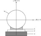
- the central axis on the shape of the cylindrical ingot and the normal to the crystal plane (crystal orientation axis). This deviation will be briefly described with reference to FIG.
- the crystal orientation axis has a deviation of ⁇ x in the x-axis direction and ⁇ y in the y-axis direction with respect to the central axis on the shape of the single crystal ingot.
- a method of cutting a workpiece with a wire saw a method in which the crystal plane of the single crystal ingot and the traveling direction of the wire are aligned with each other (just angle), and a predetermined angle is set between the crystal plane and the traveling direction of the wire. Then there is a method of cutting (off-angle).
- the following methods are known for correcting the deviation of the orientation of the single crystal ingot and setting the angle (hereinafter also referred to as orientation adjustment).
- the ingot is rotated around the center axis of the ingot on the contact plate to adjust the crystal orientation in the y-axis direction, and then the ingot
- a method of adjusting the crystal orientation in the x-axis direction by changing the angle of attachment to the work holder (tilt with respect to the work plate in the x-axis direction). In this way, the azimuth can be adjusted by adjusting the rotational position of the ingot relative to the work holder and the bonding direction.
- such a method of adjusting the crystal orientation before the single crystal ingot is mounted on the wire saw is generally called an outer setup method.
- the wire saw has an orientation adjustment mechanism in the apparatus, and the orientation is adjusted inside the wire saw after setting the work holder to which the single crystal ingot is attached.
- Such a method of adjusting the crystal orientation in the wire saw after attaching the single crystal ingot to the wire saw is generally called an inner setup method.
- the difference in damage between the front and back surfaces of the cut wafer changes depending on the cutting direction (wire cutting direction) when slicing the ingot, and the slice quality (WARP, TTV) (Total Thickness Variation), swell, etc.) fluctuate greatly.
- WARP, TTV Total Thickness Variation
- swell etc.
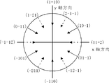
- FIG. 10 when the cutting direction is the direction represented by the solid arrow direction, the difference in damage between the front and back surfaces of the wafer is reduced.
- the cutting direction is an orientation represented by the direction of the broken-line arrow in FIG. 10
- the difference in damage between the front and back surfaces of the wafer is increased, and the slice quality is greatly deteriorated.
- a slice where the cutting direction is a direction in which the quality of the slice is greatly deteriorated cannot be implemented.
- a wire saw equipped with a single crystal ingot orientation adjusting mechanism is generally expensive, and the apparatus is limited. Furthermore, in the case of the cutting method of the inner setup method in which the orientation of the single crystal ingot is adjusted inside the wire saw as described above, the ingot cannot be cut during the orientation adjustment, so the productivity is reduced as compared with the outer setup method. There is also a problem of inviting.
- the present invention has been made in view of the above-described problems, and it is possible to cut an ingot having a strict azimuth specification by an external setup method without using a wire saw equipped with a single crystal ingot orientation adjustment mechanism. It is an object of the present invention to provide a work holder and a work cutting method using the work holder.
- the present invention is a work holder used for holding the work when cutting a work made of a cylindrical single crystal by a wire saw, A work plate that is bonded and fixed to the work via a contact plate; and a holder body that supports the work plate from a surface opposite to a surface of the work plate to which the work is bonded and fixed.
- the workpiece plate is The deviation of the crystal orientation axis of the workpiece is corrected and bonded and fixed to the workpiece, and the workpiece holder is formed by tilting the workpiece plate in the y-axis direction to thereby hold the workpiece held on the workpiece plate. It has a function of adjusting the inclination in the y-axis direction and fixing the work plate and the work to the holder body with the adjusted inclination. It provides a work holder to.
- the work holder of the present invention can correct the deviation of the crystal orientation axis in the x-axis direction when the work plate is bonded to the work. Further, by tilting the work plate in the y-axis direction, it is possible to correct the deviation of the crystal orientation axis in the y-axis direction of the work to which the work plate is bonded and fixed. If the workpiece holder is used to adjust the azimuth in the y-axis direction without rotating the workpiece, the wire cutting direction with respect to the circumference of the workpiece becomes a direction in which the slice quality is greatly deteriorated due to the rotation of the workpiece. There is no fear.
- a work such as a single crystal ingot is cut using the work holder of the present invention, even if the ingot is an orientation ⁇ 111> axis product of a semiconductor silicon single crystal ingot, a wafer with less WARP and waviness is obtained. Can be cut out. Moreover, if the work holder of this invention is used, since the crystal orientation of a workpiece
- the work plate protrudes toward the outer side in the longitudinal direction of the work plate on the surface opposite to the surface on which the work is held.
- the holder body has a receiving portion for sandwiching the curved tip portion of the protruding portion from above and below, and the receiving portion is formed of two movable pieces that can move forward and backward.
- the curved tip is sandwiched from above and below, and the two movable pieces are tapered with a slope on the surface in contact with the curved tip of the protrusion, and the work holder
- the work plate is tilted in the y-axis direction by adjusting the positional relationship between the two movable pieces sandwiching the curved tip end portion of the protruding portion, and the tilt of the work in the y-axis direction is adjusted.
- the work holder of the present invention can have such a structure.
- the two movable pieces have a taper surface with an inclination of 30 ° to 60 ° in contact with the curved tip portion of the protrusion.
- the movable piece according to the present invention can have such a tapered surface inclination. With such an inclination, it is easy to adjust the inclination of the workpiece plate in the y-axis direction and can be securely fixed. it can. If the inclination of the tapered surface is 30 ° or more, the angle adjustment amount of the work plate inclination with respect to the movement amount of the movable piece is sufficiently large, and the time required for adjustment can be reduced. Further, if the inclination of the tapered surface is 60 ° or less, the angle adjustment amount of the work plate inclination with respect to the movement amount of the movable piece does not become too large, so that delicate angle adjustment becomes easy.
- the work plate has two protrusions at both ends in the longitudinal direction
- the holder body has two receiving parts
- each receiving part has a curved shape of the two protruding parts. It is preferable to sandwich the tip from above and below.
- the workpiece plate can be adjusted at both ends in the longitudinal direction of the workpiece plate, the workpiece can be fixed by adjusting the workpiece in the y-axis direction more accurately and easily. .
- the present invention uses a wire saw provided with a wire row formed by winding a wire that reciprocates in the axial direction around a plurality of grooved rollers, and a cylindrical shape held by a work holder.
- a workpiece cutting method for cutting a workpiece by pressing a workpiece made of a single crystal against the wire row of the wire saw, the workpiece plate being bonded and fixed to the workpiece via a contact plate as the workpiece holder And a holder body that supports the work plate from a surface opposite to a surface of the work plate to which the work is bonded and fixed, and the work of the work plate is out of the radial direction of the work.
- the workpiece plate is the workpiece in the x-axis direction.
- the displacement of the crystal orientation axis is corrected and fixed to the workpiece, and the workpiece holder is configured to tilt the workpiece plate in the y-axis direction to thereby hold the y of the workpiece held on the workpiece plate.
- the crystal orientation axis shift of the workpiece in the x-axis direction is corrected and fixed to the workpiece, and the workpiece plate fixed to the workpiece is tilted in the y-axis direction to be held by the workpiece plate. Further, the inclination of the workpiece in the y-axis direction is adjusted, and the workpiece plate and the workpiece are moved to the holder body with the adjusted inclination.
- the workpiece is held by the workpiece holder, the workpiece fixed by adjusting the inclination is attached to the wire saw via the workpiece holder, and the workpiece is pressed against the wire row,
- a method for cutting a workpiece characterized by cutting a workpiece is provided.
- the work cutting method according to the present invention includes a work plate that is bonded and fixed to a work by correcting the deviation of the crystal orientation axis of the work in the x-axis direction, and further tilting the work plate in the y-axis direction, thereby Azimuth misalignment can also be corrected. If the azimuth adjustment in the y-axis direction is performed without rotating the workpiece by such a method, the cutting direction of the wire relative to the circumference of the workpiece may become a direction in which the slice quality is greatly deteriorated due to the rotation of the workpiece. There is no.
- a wafer with less WARP or waviness can be cut out even if the ingot is an orientation ⁇ 111> axis product of a semiconductor silicon single crystal ingot. it can.
- the crystal orientation of the workpiece can be adjusted by the external setup method, so that productivity can be improved. Furthermore, since an expensive wire saw equipped with an orientation adjustment mechanism is not required, the wafer can be cut at a low cost.
- the work plate protrudes toward the outer side in the longitudinal direction of the work plate on the surface opposite to the surface that holds the work.
- the tip has a curved projection
- the holder main body includes a receiving portion that sandwiches the curved tip of the projection from above and below, and the receiving portion can be moved back and forth.
- the curved top end of the protrusion is sandwiched from above and below by a movable piece, and the two movable pieces are tapered with a slope on the surface in contact with the curved top end of the protrusion.
- the work holder tilts the work plate in the y-axis direction by adjusting the positional relationship of the two movable pieces that sandwich the curved tip end portion of the projecting portion by each advancement and retraction. It can be used which can be fixed in that position while adjusting the inclination of the y-axis direction.
- the workpiece cutting method of the present invention can be implemented using a workpiece holder having such a structure.
- the two movable pieces may be those having an inclination of a tapered surface of 30 ° to 60 ° in contact with the curved tip portion of the protrusion.
- the movable piece that can be used in the present invention one having such an inclination of the tapered surface can be used. With such an inclination, the inclination of the work plate in the y-axis direction can be easily adjusted and fixed securely. be able to. If the inclination of the tapered surface is 30 ° or more, the angle adjustment amount of the work plate inclination with respect to the movement amount of the movable piece is sufficiently large, and the time required for adjustment can be reduced. Further, if the inclination of the tapered surface is 60 ° or less, the angle adjustment amount of the work plate inclination with respect to the movement amount of the movable piece does not become too large, so that delicate angle adjustment becomes easy.
- the work plate has two protrusions at both ends in the longitudinal direction, and the holder main body has two receiving parts. It is preferable to use a receiving portion that sandwiches the curved tip portions of the two protrusions from above and below.
- the work holder that can adjust the inclination of the work plate at both ends in the longitudinal direction of the work plate, the work can be fixed by adjusting the inclination of the work in the y-axis direction more accurately and easily. it can.
- the present inventor has intensively studied to solve such a problem, and the work holder capable of tilting the work in the y-axis direction shifts the crystal orientation in the y-axis direction regardless of the rotation of the work.
- the inventors have found that the above-mentioned problems can be solved by adjusting the above, and the present invention has been completed.
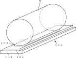
- a work holder 1 of the present invention includes a work plate 2 that is bonded and fixed to a work W via a contact plate 3, and a work plate 2 that has a surface to which the work W of the work plate 2 is bonded and fixed.
- a holder body 4 supported from the opposite surface.
- the direction parallel to the surface to which the workpiece W of the workpiece plate 2 is bonded and fixed out of the radial direction of the cylindrical workpiece W is the x-axis direction.
- the vertical direction is defined as the y-axis direction.
- the work plate 2 in the work holder 1 of the present invention is bonded and fixed to the work W by correcting the deviation of the crystal orientation axis of the work W in the x-axis direction, as shown in FIG.
- the work plate 2 is bonded and fixed to the work W by correcting the deviation ⁇ x of the crystal orientation axis in the x-axis direction.
- the work holder 1 of the present invention adjusts the inclination of the work plate 2 in the y-axis direction by inclining the work plate 2 bonded and fixed to the work W in the y-axis direction, and the work plate 2 is adjusted with the adjusted inclination.
- 2 and the work W can be fixed to the holder body 4.
- the work holder 1 can tilt and fix the work plate 2 in either a state where the work plate 2 is bonded and fixed to the work W or a state where the work plate 2 is not bonded and fixed to the work W.
- the work plate 2 has a protruding portion 5 having a curved end on the surface opposite to the surface on which the work W is held.
- the protrusion 5 may protrude toward the outside in the longitudinal direction of the work plate 2.
- curved surface shape here means shapes, such as a semi-cylinder shape and a hemisphere, for example.
- FIG. 1 shows an example in which the tip of the protrusion 5 is a semi-cylindrical shape, but the present invention is not limited to this.
- the holder body 4 has a receiving portion 6 for sandwiching the curved tip portion of the protruding portion 5 from above and below.
- the receiving portion 6 sandwiches the curved tip portion of the protruding portion 5 from above and below by the two movable pieces 6a and 6b that can move forward and backward, or the two movable pieces 6c and 6d.
- the two movable pieces 6a and 6b (6c and 6d) are tapered with an inclination on the surface in contact with the curved distal end portion of the protrusion 5.
- the movable pieces 6a and 6b (6c and 6d) can be moved forward and backward using the adjusting screws 7a and 7b (7c and 7d) connected to the respective movable pieces 6a and 6b (6c and 6d).
- the two movable pieces 6a and 6b have a taper surface with an inclination of 30 ° to 60 ° in contact with the curved tip portion of the protrusion portion 5. If the movable piece has a tapered surface with an inclination in such a range, it becomes an appropriate inclination, and the inclination of the workpiece plate 2 in the y-axis direction can be easily adjusted, and the strength is sufficient, so that a heavy workpiece can be securely fixed. Can be held. If the inclination of the tapered surface is 30 ° or more, the angle adjustment amount of the work plate inclination with respect to the movement amount of the movable piece is sufficiently large, and the time required for adjustment can be reduced. Further, if the inclination of the tapered surface is 60 ° or less, the angle adjustment amount of the work plate inclination with respect to the movement amount of the movable piece does not become too large, so that delicate angle adjustment becomes easy.
- the work plate 2 has two protrusions 5 at both ends in the longitudinal direction
- the holder body 4 has two receiving parts 6, and each receiving part 6 has two receiving parts 6. It is preferable that the curved end portions of the protrusions 5 are sandwiched from above and below, respectively.
- the tilt of the work plate 2 can be adjusted from both ends in the longitudinal direction of the work plate 2, the tilt of the work bonded to the work plate 2 in the y-axis direction can be easily adjusted with higher accuracy.
- the workpiece can be fixed.
- the work holder 1 adjusts the positional relationship of the two movable pieces sandwiching the curved tip portion of the protrusion 5 by moving the work plate 2 forward and backward. It can be tilted in the axial direction to adjust the tilt in the y-axis direction of the work W to which the work plate 2 is bonded and fixed, and can be fixed at that position.
- the movable piece 6 c is advanced inward in the longitudinal direction of the work plate 2, and the movable piece 6 d is retracted in the outward direction in the longitudinal direction of the work plate 2.
- the work plate 2 is tilted, and the work plate 2 and the work W are fixed to the holder body 4 at this position.
- the direction deviation ⁇ y can be corrected.
- the work holder of the present invention can correct the deviation of the crystal orientation axis in the x-axis direction when the work plate is bonded and fixed to the work. Further, by tilting the work plate in the y-axis direction, the azimuth adjustment in the y-axis direction can be performed without rotating the work.
- the cutting direction of the wire with respect to the circumference of the workpiece becomes a direction in which the slice quality is greatly deteriorated due to the rotation of the workpiece as in the case of using the conventional method of rotating the workpiece on the abutting plate. . That is, if a single crystal ingot is cut using the work holder of the present invention, a wafer with less WARP and waviness can be cut out by an external setup method even when the crystal orientation standard is severe. Moreover, if the work holder of this invention is used, since the crystal orientation of a workpiece
- FIG.1 and FIG.4 although the aspect which tilts a work plate was demonstrated to the example in the state which bonded and fixed the work plate 2 to the workpiece
- the work plate 2 is tilted and fixed in advance in accordance with the deviation in the y-axis direction of the crystal orientation axis of the work W to be held, and then the work plate 2 is crystallized in the x-axis direction. You may adhere and fix to the workpiece W while correcting the misalignment of the shaft.
- the work cutting method of the present invention cuts a work by using a wire saw and pressing a work made of a columnar single crystal held by a work holder against a wire row of the wire saw. More specifically, a wire saw as shown in FIG. 5 can be used.
- the wire saw 10 includes a wire row 13 formed by winding a wire 12 that reciprocates in the axial direction around a plurality of grooved rollers 11.
- a wire saw 10 can cut the workpiece W into a wafer by pressing the workpiece W made of a columnar single crystal held by the workpiece holder 1 against the wire row 13 of the wire saw 10.
- the workpiece cutting method of the present invention is an external setup method that adjusts the orientation of the workpiece before the workpiece W is mounted on the wire saw 10 via the workpiece holder 1. More specifically, first, as shown in FIG. 3, when the workpiece W is held by the workpiece holder 1, the workpiece W 2 is corrected by correcting the deviation of the crystal orientation axis of the workpiece W in the x-axis direction. (S1 in FIG. 6).
- the work plate 2 bonded and fixed to the work W is tilted in the y-axis direction, thereby adjusting the tilt of the work held by the work plate 2 in the y-axis direction (FIG. 6). S2). Then, the workpiece W is held by the workpiece holder 1 by fixing the workpiece plate 2 and the workpiece W to the holder body 4 with the adjusted inclination (S3 in FIG. 6). Thereby, the orientation adjustment of the workpiece W is completed.
- the workpiece W having a fixed inclination is attached to the wire saw 10 via the workpiece holder 1 (S4 in FIG. 6).
- the workpiece W is cut by pressing the workpiece W against the wire row 13 in FIG. 5 (S5 in FIG. 6).
- Such a method for cutting a workpiece according to the present invention corrects the displacement of the crystal orientation axis in the x-axis direction when fixing the workpiece plate to the workpiece, and then tilts the workpiece while being fixed to the workpiece plate.
- the azimuth adjustment in the y-axis direction is performed regardless of the rotation of. Therefore, there is no possibility that the cutting direction of the wire with respect to the circumference of the workpiece becomes a direction in which the slice quality is greatly deteriorated as in the case of using the above-described method of rotating the workpiece on the plate. Therefore, if a single crystal ingot is cut by the work cutting method of the present invention, a wafer with less WARP or waviness can be cut even if the crystal orientation standard is severe.
- work cutting method of this invention can adjust the crystal orientation of a workpiece
- the work plate 2 has a protrusion 5
- the holder body 4 is a curved tip of the protrusion 5.
- a work holder 1 having a receiving portion 6 made up of two movable pieces that sandwich the portion from above and below can be used. By using such a work holder 1, the azimuth adjustment in the y-axis direction can be accurately performed.
- the two movable pieces 6a and 6b have a taper surface having an inclination of 30 ° to 60 ° contacting the curved tip portion of the protrusion 5. If it is a movable piece having such a tapered surface, it is easy to adjust the inclination of the work plate 2 in the y-axis direction. If the inclination of the tapered surface is 30 ° or more, the angle adjustment amount of the work plate inclination with respect to the movement amount of the movable piece is sufficiently large, and the time required for adjustment can be reduced. Further, if the inclination of the tapered surface is 60 ° or less, the angle adjustment amount of the work plate inclination with respect to the movement amount of the movable piece does not become too large, so that delicate angle adjustment becomes easy.
- the work plate 2 has two protrusions 5 at both ends in the longitudinal direction, and the holder body 4 has two receiving parts 6, each receiving part. It is preferable to use a portion 6 that sandwiches the curved tip portions of the two protruding portions 5 from above and below. As described above, if the tilt of the work plate can be adjusted from both ends in the longitudinal direction of the work plate, the work can be fixed by adjusting the tilt of the work in the y-axis direction with higher accuracy.
- Example 1 Using the work holder 1 of the present invention as shown in FIG. 1 and using a silicon single crystal ingot having a crystal axis ⁇ 100> with a diameter of 200 mm according to the flow of the work cutting method of the present invention shown in FIG. The workpiece was cut.
- Example 1 the work plate 2 is bonded and fixed to the ingot so that the deviation in the x-axis direction of the ingot of the crystal axis ⁇ 100> is 0 minutes, and the deviation in the y-axis direction is 20 minutes.
- the angle of the work plate 2 was adjusted, and the ingot was fixed to the holder body 4.
- the ingot held by the work holder 1 of the present invention was attached to a wire saw 10 as shown in FIG. 5 and cut.
- Example 2 The ingot was cut under the same conditions as in Example 1 except that the ingot to be cut was changed to the crystal axis ⁇ 111>.
- Table 1 shows the surface orientation, TTV, and WARP of the cut wafers in Examples 1 and 2.
- the difference between the target orientation and the measured value was 2 minutes or less in the x-axis direction and 1 minute or less in the y-axis direction. Normally, this difference is about ⁇ 10 minutes, so that it can be said that a wafer having a desired plane orientation could be cut out with high accuracy.
- TTV and WARP the crystal axis ⁇ 100> product and the crystal axis fixed at an appropriate ingot cutting position ⁇
- TTV is about 10 ⁇ m
- WARP is about 15 ⁇ m.
- the TTV and WARP of the wafers cut out in Examples 1 and 2 can be suppressed to the same extent as in the conventional case. Since the cutting method of the present invention does not include a procedure for rotating the ingot on the plate, deterioration of WARP and TTV can be suppressed even when cutting the orientation ⁇ 111> axis product of the silicon single crystal ingot.
- Comparative Example 2 The ingot was cut in the same manner as in Comparative Example 1 except that the silicon single crystal ingot was rotated 15 ° more on the workpiece holder than in Comparative Example 1 to adjust the crystal orientation in the y-axis direction.
- Comparative Example 3 The ingot was cut in the same manner as in Comparative Example 1 except that the silicon single crystal ingot was rotated 30 ° more on the workpiece holder than in Comparative Example 1 to adjust the crystal orientation in the y-axis direction.
- the cutting direction in this case was the ( ⁇ 12-1) direction in FIG.
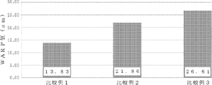
- FIG. 11 shows the WARP values of the cut wafers in Comparative Examples 1 to 3.
- the WARP of the wafer changed, and in particular, in Comparative Example 3 where the cutting direction was ( ⁇ 12-1), the WARP value increased extremely.
- the conventional method may impair the flatness of the wafer when the azimuth ⁇ 111> axis product is cut.
- the present invention is not limited to the above embodiment.
- the above-described embodiment is an exemplification, and the present invention has any configuration that has substantially the same configuration as the technical idea described in the claims of the present invention and that exhibits the same effects. Are included in the technical scope.
Landscapes
- Engineering & Computer Science (AREA)
- Mechanical Engineering (AREA)
- Processing Of Stones Or Stones Resemblance Materials (AREA)
- Mechanical Treatment Of Semiconductor (AREA)
- Finish Polishing, Edge Sharpening, And Grinding By Specific Grinding Devices (AREA)
Abstract
Description
前記ワークに当板を介して接着固定されるワークプレートと、該ワークプレートを、前記ワークプレートの前記ワークが接着固定される面とは反対側の面から支持するホルダー本体とを具備し、前記ワークの径方向のうち、前記ワークプレートの前記ワークが接着固定される面に平行な方向をx軸方向、垂直な方向をy軸方向とした場合、前記ワークプレートは、前記x軸方向の前記ワークの結晶方位軸のズレを修正して前記ワークに接着固定されるものであり、前記ワークホルダーは、前記ワークプレートを前記y軸方向に傾けることで、前記ワークプレートに保持される前記ワークの前記y軸方向の傾きを調整し、該調整された傾きで前記ワークプレート及び前記ワークを前記ホルダー本体に固定できる機能を有するものであることを特徴とするワークホルダーを提供する。
図1に示すような、本発明のワークホルダー1を使用して、図6に示した本発明のワークの切断方法のフローに従い、直径200mmの結晶軸<100>のシリコン単結晶インゴットを用いて、ワークの切断を行った。
切断するインゴットを結晶軸<111>のものに変更したこと以外、実施例1と同様な条件でインゴットを切断した。

ワークホルダーの当板上でシリコン単結晶インゴットを回転させ、y軸方向の結晶方位を調整し、インゴットのワークホルダーへの貼り付け角度(x軸方向のワークプレートに対する傾き)を変えることでx軸方向の結晶方位を調整することで、方位調整を行った。その後、ワークホルダーをワイヤソーに装着し、インゴットの切断を行った。ここで使用したシリコン単結晶インゴットは、直径200mmの方位<111>軸品である。また、切断方向は、図10の(-110)方向であった。
比較例1よりもワークホルダーの当板上でシリコン単結晶インゴットを15°多く回転させ、y軸方向の結晶方位を調整したこと以外、比較例1と同様にしてインゴットを切断した。
比較例1よりもワークホルダーの当板上でシリコン単結晶インゴットを30°多く回転させ、y軸方向の結晶方位を調整したこと以外、比較例1と同様にしてインゴットを切断した。この場合の切断方向は、図10の(-12-1)方向であった。
Claims (8)
- ワイヤソーによって円柱状の単結晶からなるワークを切断する際に前記ワークを保持するために用いられるワークホルダーであって、
前記ワークに当板を介して接着固定されるワークプレートと、
該ワークプレートを、前記ワークプレートの前記ワークが接着固定される面とは反対側の面から支持するホルダー本体とを具備し、
前記ワークの径方向のうち、前記ワークプレートの前記ワークが接着固定される面に平行な方向をx軸方向、垂直な方向をy軸方向とした場合、前記ワークプレートは、前記x軸方向の前記ワークの結晶方位軸のズレを修正して前記ワークに接着固定されるものであり、
前記ワークホルダーは、前記ワークプレートを前記y軸方向に傾けることで、前記ワークプレートに保持される前記ワークの前記y軸方向の傾きを調整し、該調整された傾きで前記ワークプレート及び前記ワークを前記ホルダー本体に固定できる機能を有するものであることを特徴とするワークホルダー。 - 前記ワークプレートが、前記ワークを保持する側の面とは反対側の面に、前記ワークプレートの長手方向の外側に向けて突き出た、先端部が曲面状の突起部を有し、
前記ホルダー本体が、前記突起部の曲面状の先端部を上下から挟み込む受け部を有し、該受け部は、2個の進退動可能な可動コマによって前記突起部の曲面状の先端部を上下から挟み込むものであり、前記2個の可動コマは、前記突起部の曲面状の先端部と接する面に傾きを有するテーパー状のものであり、
前記ワークホルダーは、前記突起部の曲面状の先端部を挟み込む前記2個の可動コマの位置関係を各々の進退動により調整することで、前記ワークプレートをy軸方向に傾け、前記ワークの前記y軸方向の傾きを調整するとともにその位置で固定することが可能なものであることを特徴とする請求項1に記載のワークホルダー。 - 前記2個の可動コマは、前記突起部の曲面状の先端部と接するテーパー面の傾きが30°~60°のものであることを特徴とする請求項2に記載のワークホルダー。
- 前記ワークプレートが前記突起部を長手方向の両端に2個有するとともに、前記ホルダー本体が前記受け部を2個有し、各々の受け部が、前記2個の突起部の曲面状の先端部をそれぞれ上下から挟み込むものであることを特徴とする請求項2又は請求項3に記載のワークホルダー。
- 複数の溝付きローラに軸方向に往復走行するワイヤを巻掛けて形成されたワイヤ列を具備するワイヤソーを用い、ワークホルダーで保持した円柱状の単結晶からなるワークを前記ワイヤソーの前記ワイヤ列に押し当てることで、ワークを切断するワークの切断方法であって、
前記ワークホルダーとして、
前記ワークに当板を介して接着固定されるワークプレートと、
該ワークプレートを、前記ワークプレートの前記ワークが接着固定される面とは反対側の面から支持するホルダー本体とを具備し、
前記ワークの径方向のうち、前記ワークプレートの前記ワークが接着固定される面に平行な方向をx軸方向、垂直な方向をy軸方向とした場合、前記ワークプレートは、前記x軸方向の前記ワークの結晶方位軸のズレを修正して前記ワークに接着固定されるものであり、
前記ワークホルダーは、前記ワークプレートを前記y軸方向に傾けることで、前記ワークプレートに保持される前記ワークの前記y軸方向の傾きを調整し、該調整された傾きで前記ワークプレート及び前記ワークを前記ホルダー本体に固定できる機能を有するものを用い、
前記ワークホルダーで前記ワークを保持する際に、前記ワークプレートを前記x軸方向の前記ワークの結晶方位軸のズレを修正して前記ワークに接着固定し、
前記ワークに接着固定された前記ワークプレートを前記y軸方向に傾けることで、前記ワークプレートに保持された前記ワークの前記y軸方向の傾きを調整し、該調整された傾きで前記ワークプレート及び前記ワークを前記ホルダー本体に固定することで、前記ワークホルダーで前記ワークを保持し、
前記傾きを調整して固定したワークを前記ワークホルダーを介して前記ワイヤソーに取り付け、前記ワークを前記ワイヤ列に押し当てることで、前記ワークを切断することを特徴とするワークの切断方法。 - 前記ワークホルダーとして、前記ワークプレートが、前記ワークを保持する側の面とは反対側の面に、前記ワークプレートの長手方向の外側に向けて突き出た、先端部が曲面状の突起部を有し、
前記ホルダー本体が、前記突起部の曲面状の先端部を上下から挟み込む受け部を具備し、該受け部は、2個の進退動可能な可動コマによって前記突起部の曲面状の先端部を上下から挟み込むものであり、前記2個の可動コマは、前記突起部の曲面状の先端部と接する面に傾きを有するテーパー状のものであり、
前記ワークホルダーは、前記突起部の曲面状の先端部を挟み込む前記2個の可動コマの位置関係を各々の進退動により調整することで、前記ワークプレートをy軸方向に傾け、前記ワークの前記y軸方向の傾きを調整するとともにその位置で固定することが可能なものを用いることを特徴とする請求項5に記載のワークの切断方法。 - 前記2個の可動コマは、前記突起部の曲面状の先端部と接するテーパー面の傾きが30°~60°のものを用いることを特徴とする請求項6に記載のワークの切断方法。
- 前記ワークホルダーとして、前記ワークプレートが前記突起部を長手方向の両端に2個有するとともに、前記ホルダー本体が前記受け部を2個有し、各々の受け部が、前記2個の突起部の曲面状の先端部をそれぞれ上下から挟み込むものを用いることを特徴とする請求項6又は請求項7に記載のワークの切断方法。
Priority Applications (5)
| Application Number | Priority Date | Filing Date | Title |
|---|---|---|---|
| CN201680040269.XA CN107848092B (zh) | 2015-07-27 | 2016-07-12 | 工件支架及工件的切断方法 |
| KR1020187002347A KR102545512B1 (ko) | 2015-07-27 | 2016-07-12 | 워크홀더 및 워크의 절단방법 |
| US15/746,941 US10596724B2 (en) | 2015-07-27 | 2016-07-12 | Workpiece holder and method for slicing workpiece |
| DE112016002951.9T DE112016002951T5 (de) | 2015-07-27 | 2016-07-12 | Werkstückhalter und Verfahren zum Schneiden eines Werkstücks |
| SG11201800299PA SG11201800299PA (en) | 2015-07-27 | 2016-07-12 | Workpiece holder and method for slicing workpiece |
Applications Claiming Priority (2)
| Application Number | Priority Date | Filing Date | Title |
|---|---|---|---|
| JP2015148107A JP6272801B2 (ja) | 2015-07-27 | 2015-07-27 | ワークホルダー及びワークの切断方法 |
| JP2015-148107 | 2015-07-27 |
Publications (1)
| Publication Number | Publication Date |
|---|---|
| WO2017017919A1 true WO2017017919A1 (ja) | 2017-02-02 |
Family
ID=57884150
Family Applications (1)
| Application Number | Title | Priority Date | Filing Date |
|---|---|---|---|
| PCT/JP2016/003287 Ceased WO2017017919A1 (ja) | 2015-07-27 | 2016-07-12 | ワークホルダー及びワークの切断方法 |
Country Status (8)
| Country | Link |
|---|---|
| US (1) | US10596724B2 (ja) |
| JP (1) | JP6272801B2 (ja) |
| KR (1) | KR102545512B1 (ja) |
| CN (1) | CN107848092B (ja) |
| DE (1) | DE112016002951T5 (ja) |
| SG (1) | SG11201800299PA (ja) |
| TW (1) | TWI684489B (ja) |
| WO (1) | WO2017017919A1 (ja) |
Families Citing this family (8)
| Publication number | Priority date | Publication date | Assignee | Title |
|---|---|---|---|---|
| WO2019167100A1 (ja) * | 2018-02-27 | 2019-09-06 | 株式会社Sumco | 半導体単結晶インゴットのスライス方法 |
| JP6969579B2 (ja) * | 2019-01-15 | 2021-11-24 | 信越半導体株式会社 | ワークの切断方法及びワイヤソー |
| JP7148437B2 (ja) | 2019-03-01 | 2022-10-05 | 信越半導体株式会社 | ワークの切断加工方法及びワークの切断加工装置 |
| CN111761745B (zh) * | 2020-06-01 | 2022-08-30 | 徐州鑫晶半导体科技有限公司 | 线切割机的晶向偏差检测方法、粘棒方法和存储介质 |
| KR102740967B1 (ko) | 2022-01-10 | 2024-12-11 | 에스케이실트론 주식회사 | 잉곳의 y축 보정용 워크플레이트 및 이를 이용한 잉곳의 y축 보정 방법 |
| CN114551638A (zh) * | 2022-01-21 | 2022-05-27 | 无锡松煜科技有限公司 | 一种石英舟插片方法和取片方法 |
| CN114714526A (zh) * | 2022-04-01 | 2022-07-08 | 宁夏中欣晶圆半导体科技有限公司 | 二维调整单晶硅棒晶向的接着方法 |
| CN114905647A (zh) * | 2022-05-13 | 2022-08-16 | 西安奕斯伟材料科技有限公司 | 一种用于定位待被线切割的晶棒的定位装置和线切割机 |
Citations (5)
| Publication number | Priority date | Publication date | Assignee | Title |
|---|---|---|---|---|
| JPH11147217A (ja) * | 1997-11-17 | 1999-06-02 | Nippei Toyama Corp | ワークの結晶方位調整方法 |
| JP2000026200A (ja) * | 1998-06-04 | 2000-01-25 | Wacker Siltronic G Fuer Halbleitermaterialien Ag | 円柱形単結晶の製造方法及び装置、並びに半導体ウェ―ハの切断方法 |
| JP2001050912A (ja) * | 1999-08-11 | 2001-02-23 | Rigaku Corp | 単結晶インゴットの支持装置、単結晶インゴットの測定装置及び単結晶インゴットの測定方法 |
| JP2004533347A (ja) * | 2001-06-13 | 2004-11-04 | フライベルガー・コンパウンド・マテリアルズ・ゲゼルシャフト・ミット・ベシュレンクテル・ハフツング | 結晶外面に対する結晶面の方位を決定する装置及び方法、及び切断機にて単結晶を切断する装置及び方法 |
| JP2015050215A (ja) * | 2013-08-30 | 2015-03-16 | 株式会社Sumco | インゴットとワークホルダの接着方法及び接着装置 |
Family Cites Families (18)
| Publication number | Priority date | Publication date | Assignee | Title |
|---|---|---|---|---|
| CA1119811A (en) * | 1980-01-25 | 1982-03-16 | Cominco Ltd. | Cutting apparatus for semi-conductor materials |
| JP2909945B2 (ja) * | 1992-10-09 | 1999-06-23 | コマツ電子金属株式会社 | 種棒切断方法 |
| CH690845A5 (de) * | 1994-05-19 | 2001-02-15 | Tokyo Seimitsu Co Ltd | Verfahren zum Positionieren eines Werkstücks und Vorrichtung hierfür. |
| TW355151B (en) * | 1995-07-07 | 1999-04-01 | Tokyo Seimitsu Co Ltd | A method for cutting single chip material by the steel saw |
| CH692331A5 (de) * | 1996-06-04 | 2002-05-15 | Tokyo Seimitsu Co Ltd | Drahtsäge und Schneidverfahren unter Einsatz derselben. |
| WO1998000273A1 (en) * | 1996-06-28 | 1998-01-08 | Crystal Systems, Inc. | Method and apparatus to produce a radial cut profile |
| JPH10321564A (ja) * | 1997-05-20 | 1998-12-04 | Tokyo Seimitsu Co Ltd | ウェーハ回収装置 |
| JP2000153517A (ja) * | 1998-11-20 | 2000-06-06 | Tokyo Seimitsu Co Ltd | ワイヤソー |
| CH697024A5 (fr) * | 2000-09-28 | 2008-03-31 | Hct Shaping Systems Sa | Dispositif de sciage par fil. |
| JP2002337137A (ja) * | 2001-05-16 | 2002-11-27 | Nippei Toyama Corp | ワーク装着方法及びワイヤソー及び支持プレート |
| JP2004262180A (ja) * | 2003-03-04 | 2004-09-24 | Sumitomo Electric Ind Ltd | スライサ切断方法とそのための設備 |
| CH696431A5 (fr) * | 2003-04-01 | 2007-06-15 | Hct Shaping Systems Sa | Procédé et dispositif de sciage par fil. |
| DE102004011991B4 (de) * | 2004-03-11 | 2008-04-17 | Siltronic Ag | Drahtsäge zum Abtrennen von Scheiben von einem Werkstück und Verfahren zum Abtrennen von Scheiben |
| JP5590001B2 (ja) * | 2011-10-04 | 2014-09-17 | 信越半導体株式会社 | ワークの切断方法及びワイヤソー |
| KR101449572B1 (ko) * | 2013-03-25 | 2014-10-13 | 한국생산기술연구원 | 리프트-업 스윙을 구현하는 와이어 쏘 |
| JP6132621B2 (ja) | 2013-03-29 | 2017-05-24 | Sumco Techxiv株式会社 | 半導体単結晶インゴットのスライス方法 |
| CN203510499U (zh) * | 2013-09-30 | 2014-04-02 | 洛阳鸿泰半导体有限公司 | 一种调整硅棒晶向偏离度的装置 |
| CN204196015U (zh) * | 2014-06-06 | 2015-03-11 | 云南蓝晶科技股份有限公司 | 晶棒轴线定位装置 |
-
2015
- 2015-07-27 JP JP2015148107A patent/JP6272801B2/ja active Active
-
2016
- 2016-07-12 DE DE112016002951.9T patent/DE112016002951T5/de active Pending
- 2016-07-12 CN CN201680040269.XA patent/CN107848092B/zh active Active
- 2016-07-12 KR KR1020187002347A patent/KR102545512B1/ko active Active
- 2016-07-12 WO PCT/JP2016/003287 patent/WO2017017919A1/ja not_active Ceased
- 2016-07-12 SG SG11201800299PA patent/SG11201800299PA/en unknown
- 2016-07-12 US US15/746,941 patent/US10596724B2/en active Active
- 2016-07-14 TW TW105122297A patent/TWI684489B/zh active
Patent Citations (5)
| Publication number | Priority date | Publication date | Assignee | Title |
|---|---|---|---|---|
| JPH11147217A (ja) * | 1997-11-17 | 1999-06-02 | Nippei Toyama Corp | ワークの結晶方位調整方法 |
| JP2000026200A (ja) * | 1998-06-04 | 2000-01-25 | Wacker Siltronic G Fuer Halbleitermaterialien Ag | 円柱形単結晶の製造方法及び装置、並びに半導体ウェ―ハの切断方法 |
| JP2001050912A (ja) * | 1999-08-11 | 2001-02-23 | Rigaku Corp | 単結晶インゴットの支持装置、単結晶インゴットの測定装置及び単結晶インゴットの測定方法 |
| JP2004533347A (ja) * | 2001-06-13 | 2004-11-04 | フライベルガー・コンパウンド・マテリアルズ・ゲゼルシャフト・ミット・ベシュレンクテル・ハフツング | 結晶外面に対する結晶面の方位を決定する装置及び方法、及び切断機にて単結晶を切断する装置及び方法 |
| JP2015050215A (ja) * | 2013-08-30 | 2015-03-16 | 株式会社Sumco | インゴットとワークホルダの接着方法及び接着装置 |
Also Published As
| Publication number | Publication date |
|---|---|
| US20180215075A1 (en) | 2018-08-02 |
| US10596724B2 (en) | 2020-03-24 |
| TWI684489B (zh) | 2020-02-11 |
| KR102545512B1 (ko) | 2023-06-20 |
| SG11201800299PA (en) | 2018-02-27 |
| JP2017024145A (ja) | 2017-02-02 |
| TW201703907A (zh) | 2017-02-01 |
| CN107848092B (zh) | 2020-04-21 |
| KR20180036702A (ko) | 2018-04-09 |
| JP6272801B2 (ja) | 2018-01-31 |
| CN107848092A (zh) | 2018-03-27 |
| DE112016002951T5 (de) | 2018-03-15 |
Similar Documents
| Publication | Publication Date | Title |
|---|---|---|
| JP6272801B2 (ja) | ワークホルダー及びワークの切断方法 | |
| US9876078B2 (en) | Method for slicing semiconductor single crystal ingot | |
| JP6000235B2 (ja) | ワークの切断方法及びワーク保持治具 | |
| TWI608897B (zh) | Monolithic lapping method for semiconductor wafer and monolithic lapping device for semiconductor wafer | |
| TWI750447B (zh) | 半導體單結晶鑄錠的切片方法 | |
| JP2013258243A (ja) | 化合物半導体基板の製造方法および製造装置 | |
| JP6230112B2 (ja) | ウェハの製造方法およびウェハの製造装置 | |
| JP5276851B2 (ja) | 結晶方位測定装置、結晶加工装置及び結晶加工方法 | |
| US11584037B2 (en) | Wire saw apparatus and method for manufacturing wafer | |
| US9192996B2 (en) | Wire guide, wire saw apparatus including the same, and method for slicing ingot using the same | |
| JP2012028702A (ja) | 半導体結晶固定治具 | |
| JP7148437B2 (ja) | ワークの切断加工方法及びワークの切断加工装置 | |
| JP6157421B2 (ja) | ワークの切断方法及びワーク保持治具 | |
| EP4579717A1 (en) | Cylindrical grinding device, cylindrical grinding method, and wafer manufacturing method | |
| KR20140092117A (ko) | 와이어 쏘 장치 | |
| US20230044283A1 (en) | Method of manufacturing chip | |
| KR101530254B1 (ko) | 와이어 가이드 및 이를 포함한 잉곳 절단 장치 |
Legal Events
| Date | Code | Title | Description |
|---|---|---|---|
| 121 | Ep: the epo has been informed by wipo that ep was designated in this application |
Ref document number: 16830027 Country of ref document: EP Kind code of ref document: A1 |
|
| WWE | Wipo information: entry into national phase |
Ref document number: 11201800299P Country of ref document: SG |
|
| WWE | Wipo information: entry into national phase |
Ref document number: 15746941 Country of ref document: US |
|
| ENP | Entry into the national phase |
Ref document number: 20187002347 Country of ref document: KR Kind code of ref document: A |
|
| WWE | Wipo information: entry into national phase |
Ref document number: 112016002951 Country of ref document: DE |
|
| 122 | Ep: pct application non-entry in european phase |
Ref document number: 16830027 Country of ref document: EP Kind code of ref document: A1 |