WO2017014168A1 - 窒化ケイ素焼結体およびその製造方法 - Google Patents
窒化ケイ素焼結体およびその製造方法 Download PDFInfo
- Publication number
- WO2017014168A1 WO2017014168A1 PCT/JP2016/070927 JP2016070927W WO2017014168A1 WO 2017014168 A1 WO2017014168 A1 WO 2017014168A1 JP 2016070927 W JP2016070927 W JP 2016070927W WO 2017014168 A1 WO2017014168 A1 WO 2017014168A1
- Authority
- WO
- WIPO (PCT)
- Prior art keywords
- silicon nitride
- sintered body
- crystal phase
- crystal
- mass
- Prior art date
- Legal status (The legal status is an assumption and is not a legal conclusion. Google has not performed a legal analysis and makes no representation as to the accuracy of the status listed.)
- Ceased
Links
Classifications
-
- C—CHEMISTRY; METALLURGY
- C04—CEMENTS; CONCRETE; ARTIFICIAL STONE; CERAMICS; REFRACTORIES
- C04B—LIME, MAGNESIA; SLAG; CEMENTS; COMPOSITIONS THEREOF, e.g. MORTARS, CONCRETE OR LIKE BUILDING MATERIALS; ARTIFICIAL STONE; CERAMICS; REFRACTORIES; TREATMENT OF NATURAL STONE
- C04B35/00—Shaped ceramic products characterised by their composition; Ceramics compositions; Processing powders of inorganic compounds preparatory to the manufacturing of ceramic products
- C04B35/515—Shaped ceramic products characterised by their composition; Ceramics compositions; Processing powders of inorganic compounds preparatory to the manufacturing of ceramic products based on non-oxide ceramics
- C04B35/58—Shaped ceramic products characterised by their composition; Ceramics compositions; Processing powders of inorganic compounds preparatory to the manufacturing of ceramic products based on non-oxide ceramics based on borides, nitrides, i.e. nitrides, oxynitrides, carbonitrides or oxycarbonitrides or silicides
- C04B35/584—Shaped ceramic products characterised by their composition; Ceramics compositions; Processing powders of inorganic compounds preparatory to the manufacturing of ceramic products based on non-oxide ceramics based on borides, nitrides, i.e. nitrides, oxynitrides, carbonitrides or oxycarbonitrides or silicides based on silicon nitride
-
- H—ELECTRICITY
- H05—ELECTRIC TECHNIQUES NOT OTHERWISE PROVIDED FOR
- H05K—PRINTED CIRCUITS; CASINGS OR CONSTRUCTIONAL DETAILS OF ELECTRIC APPARATUS; MANUFACTURE OF ASSEMBLAGES OF ELECTRICAL COMPONENTS
- H05K1/00—Printed circuits
- H05K1/02—Details
- H05K1/03—Use of materials for the substrate
Definitions
- the present invention relates to a silicon nitride sintered body having high thermal conductivity that can be suitably used for a substrate of a semiconductor device and the like, and a method for producing the same.
- Patent Document 1 Japanese Patent Laid-Open No. 2009-280494 (Patent Document 1) suppresses generation of a leakage current of a power module, and can greatly improve insulation and operational reliability even when power is increased and capacity is increased.
- a power module there are no microcracks having a width of 1 ⁇ m or more on the surface of a silicon nitride sintered body having a thickness of 1.5 mm or less, and 0 to 2 submicron cracks having a width of less than 1 ⁇ m per 100 ⁇ m 2 unit area.
- the current leakage value is 420 nA or less when an alternating voltage of 1.5 kV-100 Hz is applied between the front and back surfaces of the silicon nitride sintered body, comprising a silicon nitride sintered body at a temperature of 25 ° C. and a humidity of 70%.
- a power module formed by mounting a semiconductor element provided with a plate, the silicon nitride ceramic substrate discloses a power module contains 0.5 to 3.0 mass% in terms of Mg to MgO.
- Patent Document 1 Japanese Patent Application Laid-Open No. 2009-280494
- Patent Document 1 has a low productivity because it requires a slow cooling rate of 100 ° C./hour or less after sintering in order to obtain high thermal conductivity. There was a problem.
- a silicon nitride ceramic substrate having higher thermal conductivity has been desired.
- an object of the present invention is to provide a silicon nitride sintered body having a high thermal conductivity and a method for producing the same, which can be suitably used for a substrate of a semiconductor device.
- the silicon nitride sintered body according to an embodiment of the present invention is a silicon nitride sintered body containing silicon nitride, yttrium, magnesium and oxygen.
- the silicon nitride sintered body includes a plurality of silicon nitride crystal particles and a grain boundary phase that is a portion other than the silicon nitride crystal particles.
- the grain boundary phase includes a Y 20 N 4 Si 12 O 48 crystal phase, or a Y 20 N 4 Si 12 O 48 crystal phase and a Y 2 Si 3 N 3 O 4 crystal phase.
- the intensity of the X-ray diffraction peak due to the (211) plane of the Y 2 Si 3 N 3 O 4 crystal phase relative to the intensity of the X-ray diffraction peak due to the (112) plane of the Y 20 N 4 Si 12 O 48 crystal phase The ratio is 0 or more and 3.0 or less.
- a method for producing a silicon nitride sintered body according to another aspect of the present invention is a method for producing a silicon nitride sintered body according to the above aspect, wherein the ⁇ crystal phase ratio of the raw material silicon nitride powder is 5% by mass or more. 40% by mass or less.
- the silicon nitride sintered body according to an embodiment of the present invention is a silicon nitride sintered body containing silicon nitride, yttrium, magnesium, and oxygen.
- the silicon nitride sintered body includes a plurality of silicon nitride crystal particles and a grain boundary phase that is a portion other than the silicon nitride crystal particles.
- the grain boundary phase includes a Y 20 N 4 Si 12 O 48 crystal phase, or a Y 20 N 4 Si 12 O 48 crystal phase and a Y 2 Si 3 N 3 O 4 crystal phase.
- the intensity of the X-ray diffraction peak due to the (211) plane of the Y 2 Si 3 N 3 O 4 crystal phase relative to the intensity of the X-ray diffraction peak due to the (112) plane of the Y 20 N 4 Si 12 O 48 crystal phase The ratio is 0 or more and 3.0 or less.
- the silicon nitride sintered body of the present embodiment has a high thermal conductivity.
- the plurality of silicon nitride crystal particles included in the silicon nitride sintered body of the present embodiment have a minor axis particle size of 1.7 ⁇ m or more and 10.5 ⁇ m or less, and an aspect ratio that is a ratio of the major axis particle size to the minor axis particle size Can be 2.0 or more and 7.7 or less.
- Such a silicon nitride sintered body has a high thermal conductivity.
- the content of various impurity metal elements other than silicon, yttrium, and magnesium can be 0.5% by mass or less.
- Such a silicon nitride sintered body has a high thermal conductivity.
- Such a silicon nitride sintered body of this embodiment it is possible to prevent the magnesium oxide crystal phase from being present.
- Such a silicon nitride sintered body has a high relative density and a high thermal conductivity.
- the thermal conductivity can be 95 W ⁇ m ⁇ 1 ⁇ K ⁇ 1 or more.
- Such a silicon nitride sintered body has a high thermal conductivity.
- the area ratio of the grain boundary phase to the silicon nitride crystal particles in the arbitrarily specified cross section of the silicon nitride sintered body can be 10% or less.
- Such a silicon nitride sintered body has a high thermal conductivity.
- a method for producing a silicon nitride sintered body according to another embodiment of the present invention is a method for producing a silicon nitride sintered body according to the above embodiment, wherein the ⁇ crystal phase ratio of the raw material silicon nitride powder is 5% by mass or more. 40% by mass or less.
- the silicon nitride sintered body having high thermal conductivity can be obtained by the method for producing a silicon nitride sintered body of the present embodiment.
- the silicon nitride sintered body of the present embodiment is a silicon nitride sintered body containing silicon nitride (Si 3 N 4 ), yttrium (Y), magnesium (Mg), and oxygen (O).
- the silicon nitride sintered body includes a plurality of silicon nitride (Si 3 N 4 ) crystal particles and a grain boundary phase that is a portion other than the Si 3 N 4 crystal particles.
- the grain boundary phase includes a Y 20 N 4 Si 12 O 48 crystal phase, or a Y 20 N 4 Si 12 O 48 crystal phase and a Y 2 Si 3 N 3 O 4 crystal phase.
- the ratio I Y2 / I Y20 of the intensity I Y2 is 0 or more and 3.0 or less.
- the silicon nitride sintered body of the present embodiment has a high thermal conductivity.
- the silicon nitride sintered body of the present embodiment contains Si 3 N 4 , Y, Mg and O.
- the progress of sintering of Si 3 N 4 crystal particles that is, densification and particle growth, followed by capillary aggregation due to the liquid phase formation of the initial sintering aid, followed by ⁇ -Si 3 N 4 which is Si 3 N 4 crystal particles.
- the thermal conductivity of the obtained silicon nitride sintered body is lowered. Since Y traps solid solution oxygen, the solid solution of oxygen (O) in the Si 3 N 4 crystal particles can be suppressed, so that the crystal structure of the ⁇ -Si 3 N 4 crystal phase is not disturbed. Further, Y may, for ⁇ -Si 3 N 4 is not a solid solution in the crystal phase, the crystal structure of ⁇ -Si 3 N 4 crystal phase is not disturbed. The disorder of the crystal structure inhibits heat conduction and is not desirable for increasing the thermal conductivity. For this reason, the sintering aid containing Y is effective in improving the thermal conductivity. Mg is, Si 3 N 4 for lowering the melting point of the oxide or oxynitride such as SiON, such as SiO x formed on the surface of the crystal grains, Si 3 N 4 essential for liquid phase sintering of the crystal grains Elements.
- the above Si 3 N 4 , Y and Mg are contained in the silicon nitride (Si 3 N 4 ) powder, yttrium oxide (Y 2 O 3 ) powder and magnesium oxide (MgO) powder as raw materials, respectively. Is present for sintering after molding and degreasing.
- the Si 3 N 4 powder is 87.6 parts by mass or more and 98.5 parts by mass or less
- the Y 2 O 3 powder is 1. It is 0 to 10.4 parts by mass
- the MgO powder is 0.5 to 2.0 parts by mass.
- the Y content when the total mass is 100% by mass, the Y content is preferably 0.5% by mass or more and 10.4% by mass or less.
- the content of Y is more preferably 0.6% by mass or more, and further preferably 2.2% by mass or more.
- the Y content is more preferably 4.0% by mass or less, and even more preferably 2.6% by mass or less.
- the Mg content is preferably 0.05% by mass or more and 0.7% by mass or less.
- the Mg content is more preferably 0.07% by mass or more, and still more preferably 0.15% by mass or more.
- the Mg content is more preferably 0.5% by mass or less, and still more preferably 0.24% by mass or less.
- the content of O is preferably 0.3% by mass or more and 2.0% by mass or less.
- the O content is more preferably 0.5% by mass or more, and still more preferably 0.8% by mass or more.
- the O content is more preferably 1.5% by mass or less, and still more preferably 1.1% by mass or less.
- the Y content when the Y content is less than 0.5 mass%, the Mg content is less than 0.05 mass%, or the O content is less than 0.3 mass%, it acts as a sintering aid. Since the content of these elements is insufficient, sintering does not proceed, so that it is difficult to obtain a relative density sufficient as a sintered body.
- the Y content is more than 10.4% by mass, the Mg content is more than 0.7% by mass, or the O content is more than 2.0% by mass, the thermal conductivity is low. Since the amount increases, the thermal conductivity of the sintered body tends to decrease.
- Si 3 N 4 For qualitative analysis of Si 3 N 4 , after X-ray diffraction using X'Pert PRO (manufactured by PANalytical) or equivalent, and PDXL2 (integrated powder X-ray analysis software (Rigaku) or equivalent software) are used.
- X'Pert PRO manufactured by PANalytical
- PDXL2 integrated powder X-ray analysis software (Rigaku) or equivalent software
- Si 3 N 4 a sintered body having a surface size of 500 ⁇ m ⁇ 500 ⁇ m or more is used.
- an international diffraction data center is used as a powder X-ray diffraction database. No.
- ICDD PDF-4 + 2014 which is a powder diffraction data file by 26191 and no.
- 79798 is used to identify which crystal type.
- X-ray diffraction is performed using a Cu-K ⁇ ray excited at 45 kV and 40 mA, scanning by the ⁇ -2 ⁇ method, a step width of 0.03 °, and an integration time of 1 second.
- ICP-AES inductively coupled plasma-emission spectroscopic analysis
- ICPS-8100 manufactured by SHIMADZU or an equivalent apparatus
- the procedure for such ICP-AES is exemplified below.
- the sintered body is pulverized with an agate mortar and pestle.
- a qualitative analysis is performed from the wavelength of the light emitted when the excited element returns to the ground state by introducing the solution of the pretreatment powder into a mist and introducing it into Ar plasma. Quantitative analysis from the intensity of Thereby, the mass% of Y and Mg present in the sintered body is quantified.
- the pretreated powder solution was prepared by pouring 0.1 g of the pretreated powder into a platinum crucible together with 2 g of calcium carbonate and 0.5 g of boron oxide in a platinum crucible and melting the melt. It is prepared by collecting at 60 ° C. in an acidic solution consisting of 20 ml of 35% by mass hydrochloric acid and 20 ml of ion exchange water, and then diluting to 200 ml with ion exchange water.
- an inert gas melting-non-dispersive infrared absorption (NDIR) method using EMGA650W manufactured by HORIBA or an equivalent apparatus is used.
- the procedure for the analysis by the inert gas melting-NDIR method will be exemplified below.
- the sintered body is pulverized with an agate mortar and pestle.
- 0.03 g of pretreated powder is placed in a carbon crucible and the CO gas and / or CO 2 gas generated when the temperature is raised to 1600 ° C. at a high frequency is present because it is above the background level. Analysis is performed, and quantitative analysis is performed from the amount of gas generated. Thereby, the mass% of O present in the sintered body is quantified.
- the silicon nitride sintered body of the present embodiment includes a plurality of silicon nitride (Si 3 N 4 ) crystal particles and a grain boundary phase that is a portion other than the Si 3 N 4 crystal particles.
- the grain boundary phase includes a Y 20 N 4 Si 12 O 48 crystal phase, or a Y 20 N 4 Si 12 O 48 crystal phase and a Y 2 Si 3 N 3 O 4 crystal phase.
- Oxygen (O) dissolved in the Si 3 N 4 crystal particles causes a reduction in the thermal conductivity of the sintered body, but when yttrium oxide (Y 2 O 3 ) is added as a sintering aid, O is more stable when present in the grain boundary phase as an oxynitride crystal phase such as Y 20 N 4 Si 12 O 48 or Y 2 Si 3 N 3 O 4 than in Si 3 N 4 crystal grains. Therefore, it is possible to reduce the amount of dissolved oxygen in the Si 3 N 4 crystal particles that causes the thermal conductivity of the sintered body to be reduced.
- Y 2 O 3 yttrium oxide
- the amount of grain boundary phase which is one of the factors for reducing the thermal conductivity of the sintered body, is reduced. Without increasing, the amount of dissolved oxygen in the Si 3 N 4 crystal particles can be reduced.
- the abundance ratio of the Y 20 N 4 Si 12 O 48 crystal phase and the Y 2 Si 3 N 3 O 4 crystal phase in the silicon nitride sintered body is not increased in the Si 3 N 4 crystal grains without increasing the amount of the grain boundary phase.
- an X-ray diffraction peak caused by the (112) plane of the Y 20 N 4 Si 12 O 48 crystal phase Y 2 Si 3 with respect to the intensity I Y20 of N 3 O 4 ratio I Y2 / I Y20 intensity I Y2 of X-ray diffraction peak due to (211) face of the crystal phase is 0 to 3.0, 0. 1 or more, more preferably 0.5 or more, and 2.5 or less, more preferably 2.0 or less.
- X-ray diffraction For X-ray diffraction, X'Pert PRO manufactured by PANalytical or an equivalent apparatus is used. For X-rays, a 40-mA Cu-K ⁇ ray under an excitation condition of 45 kV is used, and for scanning, a ⁇ -2 ⁇ method is used. The step width is 0.03 ° and the integration time is 1 second.
- PDXL2 of the integrated powder X-ray analysis software manufactured by Rigaku or equivalent software is used.
- the X-ray diffraction peak attributed to the (112) plane of the Y 20 N 4 Si 12 O 48 crystal phase refers to a peak existing on the low angle side where 2 ⁇ is between 30 and 33 °.
- ICDD PDF-4 + 2014 No. Identified using 00-030-1462.
- the X-ray diffraction peak attributed to the (211) plane of the Y 2 Si 3 N 3 O 4 crystal phase refers to the peak existing on the high angle side between 2 ⁇ and 30 to 33 °.
- Powder diffraction by the International Diffraction Data Center No. of ICDD PDF-4 + 2014 which is a data file. Identified using 01-076-0724.
- sintering is performed after sintering at a high temperature of 1950 ° C. or higher. It is preferable to rapidly cool from the temperature to 1000 ° C. at a cooling rate of 100 ° C./min or more. Since the diffusion rate of Y is increased by sintering at a high temperature of 1950 ° C. or higher, the Y 20 N 4 Si 12 O 48 crystal phase is more effectively formed and rapidly cooled at a cooling rate of 100 ° C./min or higher.
- the cooling rate is more preferably 120 ° C./min or more.
- the raw material silicon nitride (Si 3 N 4 ) powder used in the production of the silicon nitride sintered body of the present embodiment has a ⁇ crystal phase ratio ( ⁇ -Si 3 N 4 crystal phase and ⁇ -Si 3 N 4 crystal).
- the ⁇ crystal phase ratio is more preferably 10% by mass or more, and still more preferably 20% by mass or more.
- the ⁇ crystal phase ratio is more preferably 35% by mass or less, and further preferably 32% by mass or less.
- the calculation of the ⁇ crystal phase ratio is performed after identifying the ⁇ -Si 3 N 4 crystal phase and the ⁇ -Si 3 N 4 crystal phase in the raw material Si 3 N 4 powder by X-ray diffraction as described above. RIR (reference intensity ratio) method is used.
- the raw material Si 3 N 4 powder should not be used only with the imide decomposition powder conventionally used as a structural material, but with direct nitriding powder or a mixed powder of direct nitriding powder and imide decomposition powder.
- the direct nitriding powder has a ⁇ crystal phase ratio of 20% by mass or more and 60% by mass or less
- the imide decomposition powder has a ⁇ crystal phase ratio of 1% by mass or less. From this, the raw material silicon nitride powder can be adjusted to a ⁇ crystal phase ratio of 5 mass% or more and 40 mass% or less by directly adjusting the content of the nitride powder.
- X'Pert PRO made by PANalytical or X-ray diffraction by equivalent equipment
- PDXL2 of Rigaku's integrated powder X-ray analysis software or equivalent software
- ICDD PDF-4 + 2014 No. 1 was used as a powder X-ray diffraction database. 26191 and no. 79798, respectively, and quantified by RIR (reference intensity ratio) method.
- X-ray diffraction is performed using a Cu-K ⁇ ray excited at 45 kV and 40 mA, scanning by the ⁇ -2 ⁇ method, a step width of 0.03 °, and an integration time of 1 second.
- the influence of the ⁇ crystal phase ratio of the raw material on the crystal phase of the grain boundary phase is unknown, but at present, it is considered as follows.
- the crystal phase of the grain boundary phase is affected by the crystal system of Si 3 N 4 because it is in close contact with the Si 3 N 4 particles.
- the sintering of the Si 3 N 4 crystal particles is performed by dissolving the ⁇ -Si 3 N 4 crystal phase and the ⁇ -Si 3 N 4 crystal phase in the sintering aid liquid phase, and ⁇ - It proceeds by reprecipitation as a Si 3 N 4 crystal phase.
- the short axis particle size of the Si 3 N 4 crystal particles in the sintered body is preferably 1.7 ⁇ m or more and 10.5 ⁇ m or less from the viewpoint of having high thermal conductivity.
- the aspect ratio which is the ratio of the major axis grain size to the minor axis grain size of the Si 3 N 4 crystal grains, is preferably 2.0 or more and 7.7 or less.
- the minor axis particle size of the Si 3 N 4 crystal particles in the sintered body is more preferably 1.8 ⁇ m or more, and further preferably 2.2 ⁇ m or more.
- the aspect ratio which is the ratio of the major axis particle size to the minor axis particle size of the Si 3 N 4 crystal particles, is more preferably 2.5 or more, 3.0 or more is further more preferable, 7.5 or less is more preferable, and 7.0 or less is further more preferable.
- SEM scanning electron microscope
- EBSD electron beam backscatter diffraction
- the SEM-EBSD measurement procedure is illustrated below.
- pre-processing after grinding to a depth of 500 ⁇ m or more from the surface of the sintered body using a diamond grindstone (Diamond grindstone # 400 made by Allied Material) using a surface grinder, use a lapping machine made by Kemet And finish processing.
- the sintered body is polished from its surface to a depth of 10 ⁇ m or more using a copper surface plate and a diamond grindstone having a particle size of 3 ⁇ m.
- a tin surface plate and a diamond grindstone having a particle size of 0.5 ⁇ m are polished.
- the sintered body is polished to a depth of 3 ⁇ m or more from the ground surface.
- both polishings in the finishing process are performed under conditions of a rotational speed of 50 rpm and a load of 0.2 MPa.
- the surface processing may be processing equivalent to the above.
- the EBSD measurement is performed with a measurement area of 30 ⁇ m ⁇ 100 ⁇ m, and measurement conditions are, for example, an acceleration voltage of 15 kV, a working distance of 15 mm, a step size of 0.1 ⁇ m, a binning of 8 ⁇ 8, and an integration time of 0.01 seconds. Thereby, an IQ (image quality) map is acquired.
- each extracted Si 3 N 4 crystal particle is approximated to an ellipse, and its short axis particle size and long axis particle size are calculated.
- the aspect ratio is calculated by dividing the major axis particle size by the minor axis particle size.
- the range of the short axis particle size described in Tables 1 to 3 is the range of the minimum value and the maximum value for the five Si 3 N 4 crystal particles.
- the aspect ratios listed in Tables 1 to 3 are average values for five Si 3 N 4 crystal grains.
- the short axis particle size of the Si 3 N 4 crystal particles in the silicon nitride sintered body of the present embodiment is preferably 1.7 ⁇ m or more and 10.5 ⁇ m or less, more preferably 1.8 ⁇ m or more, and 2.2 ⁇ m or more. Is more preferable means that the minimum value and the maximum value for the five Si 3 N 4 crystal grains are included in this range.
- the aspect ratio which is the ratio of the major axis grain size to the minor axis grain size of the Si 3 N 4 crystal particles, is preferably 2.0 or more and 7.7 or less, more preferably 2.5 or more, and 3. 0 or more is more preferable, 7.5 or less is more preferable, and 7.0 or less is more preferable, which means that an average value for five Si 3 N 4 crystal grains is included in this range. Yes.
- the minimum minor axis diameter of a plurality of (specifically, five extracted above) Si 3 N 4 crystal particles in the sintered body is less than 1.7 ⁇ m, the Si 3 N 4 crystal particles Since the particle growth is insufficient, it is difficult to increase the thermal conductivity of the sintered body because the impurities in the raw material Si 3 N 4 particles are not sufficiently removed.
- the maximum minor axis diameter of the plurality of Si 3 N 4 crystal particles is larger than 10.5 ⁇ m, a long sintering time is required to obtain high thermal conductivity, and productivity is lowered and sintering is performed. The thermal conductivity of the body tends to decrease.
- the aspect ratio is larger than 7.7, the sintered density does not sufficiently increase and the thermal conductivity tends to decrease.
- the aspect ratio is less than 2.0, it is difficult to increase the thermal conductivity of the sintered body.
- the silicon nitride sintered body of the present embodiment has a high thermal conductivity by setting the ⁇ crystal phase ratio of the raw material Si 3 N 4 powder to 5 mass% or more and 40 mass% or less. Can be obtained.
- the sintering of the Si 3 N 4 crystal particles is performed by dissolving the ⁇ -Si 3 N 4 crystal phase and the ⁇ -Si 3 N 4 crystal phase in the sintering aid liquid phase, and ⁇ - It proceeds by reprecipitation as a Si 3 N 4 crystal phase. Therefore, ⁇ -Si 3 N 4 crystalline phase the Si 3 N 4 powder of raw material, the core during the re-precipitation of the ⁇ -Si 3 N 4 crystal phase from the sintering aid liquid phase.
- the ⁇ crystal phase ratio in the raw silicon nitride powder and the abundance ratio of the ⁇ -Si 3 N 4 crystal phase that becomes the nucleus when the ⁇ -Si 3 N 4 crystal phase is reprecipitated from the liquid phase of the sintering aid are the same.
- the ⁇ crystal phase ratio of the raw material Si 3 N 4 powder is less than 5% by mass, the ⁇ -Si 3 N 4 crystal phase particles that become the core of reprecipitation are reduced, and the ⁇ - Since the Si 3 N 4 crystal phase grows preferentially in one direction (abnormal particle growth), the aspect ratio becomes too large, and the sintered density of the sintered body decreases, and the thermal conductivity of the sintered body Is difficult to raise.
- the ⁇ crystal phase ratio of the raw material Si 3 N 4 powder is larger than 40% by mass, the number of ⁇ -Si 3 N 4 crystal phase particles that become the core of reprecipitation increases, and a large amount of ⁇ -Si 3 N Since the four crystal phases grow at the same time, the grain growth becomes insufficient, so the aspect ratio becomes too small and it is difficult to increase the thermal conductivity of the sintered body.
- the content of various impurity metal elements other than silicon (Si), yttrium (Y), and magnesium (Mg) is 0.5 from the viewpoint of increasing the thermal conductivity.
- the content is preferably not more than mass%, more preferably not more than 0.3 mass%, and still more preferably not more than 0.1 mass%.
- the solid solution of the impurity metal element and / or the compound in the Si 3 N 4 crystal particles causes a decrease in the thermal conductivity of the sintered body.
- a simple substance and / or compound of Al is a sialon (Si 6-Z Al Z O Z N 8-Z , where Z is from 0), which is easily dissolved in Si 3 N 4 crystal particles and has a low thermal conductivity. (Rational number up to 4) is generated, which is an inhibitor of high thermal conductivity of the sintered body.
- Quantitative analysis of impurity metal elements in the raw material powder and the sintered body uses emission spectroscopic analysis (AES) using ICP (inductively coupled plasma) as a light source.
- AES emission spectroscopic analysis
- ICP inductively coupled plasma
- the ICP-AES device for example, ICPS-8100 manufactured by SHIMADZU or an equivalent device is used.
- the procedure for ICP-AES is illustrated below.
- the sintered body is first pulverized using an agate mortar and pestle. Thereafter, 0.1 g of the pulverized sintered body powder was poured into a platinum crucible together with 2 g of calcium carbonate and 0.5 g of boron oxide in a platinum crucible and melted at 1000 ° C.
- the silicon nitride sintered body according to the present embodiment preferably has no magnesium oxide (MgO) crystal phase.
- MgO magnesium oxide
- Such a silicon nitride sintered body can reduce the amount of grain boundary phase, which is a factor of lowering thermal conductivity, by evaporating magnesium oxide (MgO) during sintering, so that high relative density and high thermal conductivity can be obtained. Can have.
- X-ray diffraction is performed to identify the MgO crystal phase in the silicon nitride sintered body.
- X'Pert PRO manufactured by PANalytical or an equivalent apparatus is used.
- X-rays 40 mA Cu-K ⁇ ray under an excitation condition of 45 kV is used, and for scanning, ⁇ -2 ⁇ method is used.
- the step width is 0.03 ° and the integration time is 1 second.
- PDXL2 of the integrated powder X-ray analysis software manufactured by Rigaku or equivalent software is used.
- the silicon nitride sintered body of the present embodiment preferably has a thermal conductivity of 95 W ⁇ m ⁇ 1 ⁇ K ⁇ 1 or more, more preferably 100 W ⁇ m ⁇ 1 ⁇ K ⁇ 1 or more, and 110 W ⁇ More preferably, it is m ⁇ 1 ⁇ K ⁇ 1 or more.
- Such a silicon nitride sintered body has high heat dissipation characteristics and is useful as a heat dissipation substrate for semiconductor devices.
- the thermal conductivity of the Si 3 N 4 sintered body is less than 95 W ⁇ m ⁇ 1 ⁇ K ⁇ 1 , the semiconductor device above the heat dissipation substrate is not sufficiently dissipated, so that the semiconductor device exceeds its heat resistance temperature. It is not possible to obtain sufficient device characteristics.
- thermal diffusivity In order to derive the thermal conductivity of the Si 3 N 4 sintered body, thermal diffusivity, specific gravity, and specific heat are required.
- an optical alternating current method scanning laser heating AC (Alternative Current) method / Angtrom method) or a laser flash method is used.
- a Laser-PIT apparatus manufactured by ULVAC or an equivalent apparatus is used. The measurement procedure with this apparatus is illustrated below.
- the AC temperature response is measured with a single thermocouple attached to the back surface of the sample by moving the laser beam in the longitudinal direction of the sample while irradiating a band-shaped laser beam with a uniform frequency of 2.5 to 10 Hz.
- the thermal diffusivity is calculated from the attenuation rate with respect to the amplitude and position of the temperature response.
- the sample shape is 2.5 to 5 mm in width, 30 mm in length, and 0.5 mm or less in thickness. Only the laser heating surface is blackened with graphite spray.
- the thermocouple and the sample are bonded with silver paste.
- TC-7000 manufactured by ULVAC or an equivalent device is used.
- the thermal diffusivity is calculated from the temperature history curve on the back surface of the test piece when the surface of the test piece is irradiated with a laser pulse (see JIS-R1611: 2010).
- the sample has a diameter of 10 mm and a thickness of 3 to 6 mm, and the entire sample is blackened with graphite spray.
- the Archimedes method is used for the specific gravity measurement, and 0.68 J ⁇ g ⁇ 1 ⁇ K ⁇ 1 is used for the specific heat.
- the silicon nitride sintered body of the present embodiment has a grain boundary phase which is a portion other than the Si 3 N 4 crystal particles with respect to the silicon nitride (Si 3 N 4 ) crystal particles in an arbitrarily specified cross section of the silicon nitride sintered body.
- the area ratio is preferably 10% or less, more preferably 9% or less, and even more preferably 6% or less.
- Such a silicon nitride sintered body can have high thermal conductivity because the area ratio of the grain boundary phase to the Si 3 N 4 crystal particles is 10% or less.
- the silicon nitride sintered body is formed of Si 3 N 4 crystal grains and other grain boundary phases.
- SEM scanning electron microscope
- EBSD electron beam backscatter diffraction
- the SEM-EBSD measurement procedure is illustrated below.
- pre-processing after grinding to a depth of 500 ⁇ m or more from the surface of the sintered body using a diamond grindstone (Diamond grindstone # 400 made by Allied Material) using a surface grinder, use a lapping machine made by Kemet And finish processing.
- the sintered body is polished from its surface to a depth of 10 ⁇ m or more using a copper surface plate and a diamond grindstone having a particle size of 3 ⁇ m.
- a tin surface plate and a diamond grindstone having a particle size of 0.5 ⁇ m are polished.
- the sintered body is polished to a depth of 3 ⁇ m or more from the ground surface.
- both polishings in the finishing process are performed under conditions of a rotation speed of 50 rpm and a load of 0.2 MPa.
- the surface processing may be processing equivalent to the above.
- the EBSD measurement is performed with a measurement area of 30 ⁇ m ⁇ 100 ⁇ m and measurement conditions such as a measurement acceleration voltage of 15 kV, a working distance of 15 mm, a step size of 0.1 ⁇ m, a binning of 8 ⁇ 8, and an integration time of 0.01 seconds, and an IQ (image quality) map.
- measurement conditions such as a measurement acceleration voltage of 15 kV, a working distance of 15 mm, a step size of 0.1 ⁇ m, a binning of 8 ⁇ 8, and an integration time of 0.01 seconds, and an IQ (image quality) map.
- the acquired IQ map image (viewing area 30 ⁇ m ⁇ 100 ⁇ m) is binarized by ImageJ software, and in the silicon nitride sintered body, the bright portions exhibiting white are Si 3 N 4 crystal particles, and the dark portions exhibiting black are displayed.
- the grain boundary phase As the grain boundary phase, the area S of the Si 3 N 4 crystal grains and the area S B of the grain boundary phases are calculated, and the area ratio of the grain boundary phase to the Si 3 N 4 crystal grains is calculated as 100 ⁇ S B / S. .
- IQ map image used to calculate the area ratio of the grain boundary phase to the Si 3 N 4 crystal grains calculated in terms of suppression of analysis costs, the minor axis particle diameter and the aspect ratio of the the Si 3 N 4 crystal grains It may be the same as the IQ map image used for.
- the method for producing the silicon nitride sintered body of the present embodiment is not particularly limited, and for example, a raw material containing silicon nitride (Si 3 N 4 ), yttrium (Y), magnesium (Mg), and oxygen (O) is prepared.
- a silicon nitride sintered body having high thermal conductivity can be obtained with high productivity.
- the raw material preparation step is not particularly limited.
- silicon nitride (Si 3 N 4 ) powder, yttrium oxide (Y 2 O 3 ) powder, and magnesium oxide A mixed powder of (MgO) powder can be prepared.
- the mixing ratio of silicon nitride (Si 3 N 4 ) powder, yttrium oxide (Y 2 O 3 ) powder, and magnesium oxide (MgO) powder is not particularly limited, but Y 20 N 4 Si in the silicon nitride sintered body is not limited.
- the ratio of the intensity of the X-ray diffraction peak due to the (211) plane of the Y 2 Si 3 N 3 O 4 crystal phase to the intensity of the X-ray diffraction peak due to the (112) plane of the 12 O 48 crystal phase is 0 or more and 3
- the Si 3 N 4 powder is 87.6 parts by mass or more and 98 0.5 parts by mass or less
- Y 2 O 3 powder is preferably 1.0 part by mass or more and 10.4 parts by mass or less
- MgO powder is preferably 0.5 part by mass or more and 2.0 parts by mass or less.
- the average particle size of the Si 3 N 4 powder used as a raw material is 0.8 ⁇ m or more and 1.3 ⁇ m or less, the average particle size of Y 2 O 3 powder is 1.3 ⁇ m or more and 1.8 ⁇ m or less, and the average particle size of MgO powder is 1
- the thickness is preferably from 0.0 ⁇ m to 1.5 ⁇ m from the viewpoint of increasing the sintered density of the sintered body and increasing its thermal conductivity.
- Microtrac BEL Microtrac MT3300EX or an equivalent device is used to measure the average particle size of the Si 3 N 4 powder, Y 2 O 3 powder, and MgO powder.
- the Si 3 N 4 powder is not particularly limited, but Y 2 with respect to the intensity of the X-ray diffraction peak due to the (112) plane of the Y 20 N 4 Si 12 O 48 crystal phase in the silicon nitride sintered body.
- silicon Directly nitrided powder obtained by directly nitriding a single substance with ammonia or nitrogen in an active atmosphere such as high temperature or plasma, or silicon diimide (Si (NH) 2 ) which is a reaction product of silicon halide and ammonia ), silicon tetra amide (Si (NH 2) 4) , mixing the imide compound such as silicon nitro Gen imide (Si 2 N 2 NH) imide decomposition powder directly nitride powder obtained by thermally decomposing It is preferable that the end.
- the ⁇ crystal ratio of the raw material Si 3 N 4 powder is not particularly limited, but is preferably 5% by mass or more and 40% by mass or less from the viewpoint of obtaining a silicon nitride sintered body having high thermal conductivity. .
- the sintering of the Si 3 N 4 crystal particles is performed by dissolving the ⁇ -Si 3 N 4 crystal phase and the ⁇ -Si 3 N 4 crystal phase in the sintering aid liquid phase, and ⁇ - It proceeds by reprecipitation as a Si 3 N 4 crystal phase. Therefore, ⁇ -Si 3 N 4 crystalline phase the Si 3 N 4 powder of raw material, the core during the re-precipitation of the ⁇ -Si 3 N 4 crystal phase from the sintering aid liquid phase.
- the ⁇ crystal phase ratio in the raw silicon nitride powder and the abundance ratio of the ⁇ -Si 3 N 4 crystal phase that becomes the nucleus when the ⁇ -Si 3 N 4 crystal phase is reprecipitated from the liquid phase of the sintering aid are the same.
- the ⁇ crystal phase ratio of the raw material Si 3 N 4 powder is less than 5% by mass, the ⁇ -Si 3 N 4 crystal phase particles that become the core of reprecipitation are reduced, and the ⁇ - Since the Si 3 N 4 crystal phase preferentially grows in one direction (abnormal particle growth), the aspect ratio becomes too large, the sintered density of the sintered body decreases, and the thermal conductivity of the sintered body is reduced.
- the ⁇ crystal phase ratio of the raw material Si 3 N 4 powder is larger than 40% by mass, the number of ⁇ -Si 3 N 4 crystal phase particles that become the core of reprecipitation increases, and a large amount of ⁇ -Si 3 N Since the four crystal phases grow at the same time, the grain growth becomes insufficient, so the aspect ratio becomes too small and it is difficult to increase the thermal conductivity of the sintered body.
- the impurity element contained in the Si 3 N 4 powder is not particularly limited, but from the viewpoint of obtaining a silicon nitride sintered body having high thermal conductivity, Al, Ca, Fe and Mg are each 0.01% by mass. Hereinafter, it is preferable that O is 1.0 mass% or less.
- ICP-AES is used to identify the impurity element. Specifically, a qualitative analysis is performed from the wavelength of light emitted when an impurity element excited by returning a solution of Si 3 N 4 powder into an atomized plasma and returning to the ground state. Quantitative analysis from the intensity of Thus, Al is present in Si 3 N 4 powder, Ca, mass% of Fe and Mg obtained. A more specific procedure is illustrated below.
- the Si 3 N 4 powder solution was prepared by adding 0.1 g of pretreated Si 3 N 4 powder into a platinum crucible together with 2 g of calcium carbonate and 0.5 g of boron oxide in an alkali solvent.
- the melt is recovered at 60 ° C. in an acidic solution composed of 20 ml of 35 mass% hydrochloric acid and 20 ml of ion-exchanged water, and then diluted to 200 ml with ion-exchanged water. . Even if the intensity of light is equivalent to the background, it was set to 0.01% by mass or less.
- O is qualitatively analyzed because the raw material silicon nitride powder is put in a 0.03 g carbon crucible and the CO gas and / or CO 2 gas generated when the temperature is raised to 1600 ° C. at a high frequency exists above the background level. Quantitative analysis is performed from the amount of gas generated. Thereby, the mass% of O present in the sintered body is quantified.
- a sintering aid an organic binder, a peptizer / dispersant, a dispersion medium, and the like can be further added to the raw material.
- Examples of the sintering aid include magnesium oxide (MgO) powder, yttrium oxide (Y 2 O 3 ) powder, and the like.
- Examples of the organic binder include polyvinyl butyral (PVB).
- Examples of the deflocculant / dispersant include polycarboxylic acid compounds, polyethyleneimine compounds, polyoxyethylene derivatives, and the like.
- Examples of the dispersion medium include alcohols such as ethanol, water, and the like.
- the mixing method of the raw materials is not particularly limited, and examples thereof include ball mill mixing and ultrasonic mixing. In ball mill mixing, balls and containers made of silicon nitride are used from the viewpoint of preventing contamination of impurity elements such as iron (Fe) as much as possible.
- the raw material slurry having a volume of 0.25 to 0.5 times the volume of the ball mill mixing container to be used is filled.
- the raw slurry is homogenized by mixing for 30 minutes or more.
- ultrasonic mixing the raw material slurry is homogenized by mixing for 10 minutes or more. The presence or absence of granulation does not matter.
- the molding pressure is preferably 0.5 tf / cm 2 (weight ton / cm 2 ) or more, more preferably 0.8 tf / cm 2 or more, from the viewpoint of forming a high-density molded body.
- the degreasing sub-process is not particularly limited, and for example, degreasing can be performed under an atmospheric pressure atmospheric flow atmosphere of 800 ° C. or less until the remaining carbon amount is 1000 ppm or less.
- the carbon content in the defatted body is determined by detecting the amount of CO and / or CO 2 emitted by burning 0.1 g of pulverized powder of the defatted body in an oxygen stream at 1000 ° C. for 1 minute with an infrared detector. Is required.
- CS-230 manufactured by LECO or an equivalent device is used.
- LECO low-density polyethylene
- CS-230 manufactured by LECO or an equivalent device is used.
- high pressure high temperature conditions of 0.5 MPa or more and 1950 degreeC or more in nitrogen atmosphere.
- the Y 2 Si 3 N 3 O 4 crystal phase relative to the intensity I Y20 of the X-ray diffraction peak due to the (112) plane of the Y 20 N 4 Si 12 O 48 crystal phase in the silicon nitride sintered body Sintering silicon nitride having high thermal conductivity by producing a silicon nitride sintered body having a ratio I Y2 / I Y20 of the X-ray diffraction peak intensity I Y2 due to the (211) plane of 0 or more and 3.0 or less
- the cooling rate is preferably 100 ° C./min or more, and more preferably 120 ° C./min or more.
- a silicon nitride sintered body having high thermal conductivity can be obtained with high productivity by a cooling step having a cooling rate of preferably 100 ° C./min or more, more preferably 120 ° C./min or more.
- a silicon nitride sintered body of the present embodiment even if the holding time at the maximum temperature during sintering is not increased, if the holding time is 4 hours or more, 30 hours or less, more preferably Even if it is 17 hours or less, a silicon nitride sintered body having a thermal conductivity of 95 W ⁇ m ⁇ 1 ⁇ K ⁇ 1 or more can be obtained.
- the mass part of each raw material is the total of silicon nitride (Si 3 N 4 ) powder, yttrium oxide (Y 2 O 3 ) powder, and magnesium oxide (MgO) powder, which are all inorganic raw material powders used as raw materials.
- Si 3 N 4 silicon nitride
- Y 2 O 3 yttrium oxide
- MgO magnesium oxide
- the average particle size of the Si 3 N 4 powder is 0.8 ⁇ m to 1.3 ⁇ m
- the average particle size of the Y 2 O 3 powder is 1.3 ⁇ m to 1.8 ⁇ m
- the average particle size of the MgO powder is 1.0 ⁇ m to 1 ⁇ m. .5 ⁇ m or less.
- the average particle size of these powders was measured by a laser diffraction scattering method using Microtrac BEL Microtrac MT3300EX.
- Tables 1 to 3 show the ⁇ crystal phase ratio (% by volume) in the Si 3 N 4 powder.
- the ⁇ crystal phase ratio was quantified by X-ray diffraction.
- the Si 3 N 4 powder contained 0.1% by mass or less of Al, Ca, Fe, and Mg as impurity metal elements, and 0.5% by mass or less of O as an impurity nonmetallic element.
- the analysis of impurity metal elements uses ICP-AES and releases when the excited metal elements return to the ground state by introducing the sample solution containing the raw material Si 3 N 4 powder into a mist and introducing it into Ar plasma. Qualitative analysis was performed from the wavelength of the emitted light, and quantitative analysis was performed from the intensity of the light. Thus, Al is present in the starting material Si 3 N 4 powder, Ca, Fe, mass% of Mg was obtained.
- a solution of the raw material Si 3 N 4 powder was prepared by adding 0.1 g of the pretreated powder together with 2 g of calcium carbonate and 0.5 g of boron oxide into a platinum crucible and melting at 1000 ° C. The melt was collected at 60 ° C.
- Uniform mixed slurries were prepared by ultrasonically mixing 1 part by mass and 3 parts by mass of Celna F-216 and Celna E503, respectively, for 60 minutes.
- the Si 3 N 4 crystal particles are identified, the contents of Y, Mg, O and impurity metal elements Al and Fe are quantified, and the presence or absence of the MgO crystal phase is determined.
- the ratio I Y2 / I Y20 of the intensity I Y2 of the diffraction peak was analyzed, the area ratio of the grain boundary phase to the Si 3 N 4 crystal grains in the cross section was analyzed, and the thermal conductivity was derived.
- Tables 1-3 The results are summarized in Tables 1-3.
- the identification of the Si 3 N 4 crystal particles was carried out by X-ray diffraction as a powder X-ray diffraction database of ICDD PDF-4 + 2014 No. 26191 and no. 79798, respectively.
- X-ray diffraction was performed using a Cu-K ⁇ ray excited at 45 kV and 40 mA, scanning by the ⁇ -2 ⁇ method, a step width of 0.03 °, and an integration time of 1 second.
- Y, Mg, Al, and Fe utilized ICP-AES by ICPS-8100 manufactured by SHIMADZU.
- ICP-AES as a pretreatment, the sintered body was pulverized with an agate mortar and pestle.
- qualitative analysis is performed from the wavelength of the light emitted when the element excited by returning the ground state to the ground state by introducing the solution of the pretreatment powder into a mist and introducing it into Ar plasma. Quantitative analysis was performed from the intensity of light.
- the pretreated powder solution was prepared by pouring 0.1 g of the pretreated powder into a platinum crucible together with 2 g of calcium carbonate and 0.5 g of boron oxide in a platinum crucible and melting the melt. It was prepared by recovering at 60 ° C. in an acidic solution consisting of 20 ml of 35% by mass hydrochloric acid and 20 ml of ion exchanged water, and then diluting to 200 ml with ion exchanged water.
- the analysis of O utilized the inert gas melting-non-dispersion type infrared absorption (NDIR) method by EMGA650W made from HORIBA.
- NDIR inert gas melting-non-dispersion type infrared absorption
- the sintered substrate was pulverized with an agate mortar and pestle.
- 0.03 g of pretreated powder is put in a carbon crucible, and CO gas and / or CO 2 gas generated when the temperature is raised to 1600 ° C. at a high frequency of 20 ⁇ 2 MHz exists above the background level. Therefore, qualitative analysis was performed, and quantitative analysis was performed from the amount of gas generated.
- the presence or absence of the MgO crystal phase was confirmed by X-ray diffraction.
- X-ray diffraction X'Pert PRO manufactured by PANalytical was used.
- 40 mA Cu-K ⁇ ray was used under an excitation condition of 45 kV, and for scanning, ⁇ -2 ⁇ method was used.
- the step width was 0.03 ° and the integration time was 1 second.
- integrated powder X-ray analysis software manufactured by Rigaku was used for analysis of X-ray diffraction peaks.
- the X-ray diffraction peak attributed to the (112) plane of the Y 20 N 4 Si 12 O 48 crystal phase is a peak existing on the low angle side where 2 ⁇ is between 30 and 33 °.
- No. of ICDD PDF-4 + 2014 which is a powder diffraction data file by the diffraction data center. Identified using 00-030-1462.
- the X-ray diffraction peak due to the (211) plane of the Y 2 Si 3 N 3 O 4 crystal phase is a high-angle peak between 2 ⁇ between 30 and 33 °. No.
- SEM-EBSD measurement was used for the analysis of the minor axis grain size and aspect ratio (ratio of major axis grain size to minor axis grain size) of Si 3 N 4 crystal grains.
- SUPER 35 VP manufactured by Carl Zeiss was used, and for electron backscatter diffraction, OIM5.2 manufactured by TSL Solutions or an equivalent apparatus was used.
- OIM5.2 manufactured by TSL Solutions or an equivalent apparatus was used as a pretreatment for SEM-EBSD measurement, after grinding to a depth of 500 ⁇ m or more from the surface of the sintered body using a diamond grindstone (Diamond grindstone # 400 made by Allied Materials) using a surface grinder, manufactured by Kemet Finished using a lapping machine.
- the sintered body is polished from its surface to a depth of 10 ⁇ m using a copper surface plate and a diamond grindstone having a particle size of 3 ⁇ m.
- a tin surface plate and a diamond grindstone having a particle size of 0.5 ⁇ m are used.
- the sintered body was polished from the surface to a depth of 3 ⁇ m.
- both polishings in the finishing process were performed under conditions of a rotation speed of 50 rpm and a load of 0.2 MPa.
- EBSD measurement was performed under the conditions of a measurement area of 30 ⁇ m ⁇ 100 ⁇ m, an acceleration voltage of 15 kV, a working distance of 15 mm, a step size of 0.1 ⁇ m, a binning of 8 ⁇ 8, and an integration time of 0.01 seconds, and an IQ (image quality) map was obtained.
- IQ map image field area 30 [mu] m ⁇ 100 [mu] m
- most area from a large Si 3 N 4 crystal grains to the fifth area is large Si 3 N 4 crystal grains extracts, the five Si 3 N
- the short-axis particle size, the long-axis particle size, and the aspect ratio of the four crystal particles were calculated by ImageJ software.
- each extracted Si 3 N 4 crystal particle was approximated to an ellipse, and its short axis particle size and long axis particle size were calculated.
- the aspect ratio was calculated by dividing the major axis particle size by the minor axis particle size.
- the range of the minor axis grain size in Tables 1 to 3 was the range of the minimum value and the maximum value for the five Si 3 N 4 crystal grains.
- the aspect ratios in Tables 1 to 3 were average values for five Si 3 N 4 crystal grains.
- the sintered body is polished from its surface to a depth of 10 ⁇ m using a copper surface plate and a diamond grindstone having a particle size of 3 ⁇ m, and then using a tin surface plate and a diamond grindstone having a particle size of 0.5 ⁇ m.
- the sintered body was polished from its surface to a depth of 3 ⁇ m.
- both polishings in the finishing process were performed under conditions of a rotation speed of 50 rpm and a load of 0.2 MPa.
- an acceleration voltage of 5 kV and a working distance of 10 mm were used, and a reflected electron image was used for analysis. This image was binarized by ImageJ software, and in the silicon nitride sintered body, the bright portions exhibiting white were Si 3 N 4 crystal particles, and the dark portions exhibiting black were used as grain boundary phases.
- the thermal conductivity of the Si 3 N 4 sintered body was derived from the thermal diffusivity, specific gravity, and specific heat.
- the measurement of thermal diffusivity used the optical alternating current method.
- a Laser-PIT apparatus manufactured by ULVAC was used. With this device, the laser beam is moved in the longitudinal direction of the sample while irradiating a band laser beam with a uniform illuminance of 2.5 to 10 Hz, so that the AC temperature response is achieved by a single thermocouple attached to the back of the sample. was measured, and the thermal diffusivity was calculated from the attenuation rate with respect to the amplitude and position of the temperature response.
- the sample had a width of 2.5 to 5 mm, a length of 30 mm, and a thickness of 0.5 mm or less, and only the laser heating surface was blackened with graphite spray.
- the thermocouple and the sample were bonded with silver paste.
- the Archimedes method was used for the specific gravity measurement, and 0.68 J ⁇ g ⁇ 1 ⁇ K ⁇ 1 was used for the specific heat.
- silicon nitride, yttrium, magnesium and oxygen are included, and a plurality of silicon nitride crystal particles and a grain boundary phase which is a portion other than the silicon nitride crystal particles are included.
- the field phase includes the Y 20 N 4 Si 12 O 48 crystal phase or the Y 20 N 4 Si 12 O 48 crystal phase and the Y 2 Si 3 N 3 O 4 crystal phase, and the Y 20 N 4 Si 12 O 48 crystal phase ( 112)
- the ratio I Y2 / I Y20 of the intensity I Y2 of the X-ray diffraction peak due to the (211) plane of the Y 2 Si 3 N 3 O 4 crystal phase to the intensity I Y20 of the X-ray diffraction peak due to the plane is 0
- the silicon nitride sintered body having a value of 3.0 or less and a high thermal conductivity of 95 W ⁇ m ⁇ 1 ⁇ K ⁇ 1 or more was exhibited.
- the intensity I Y20 of the X-ray diffraction peak due to the (112) plane of the Y 20 N 4 Si 12 O 48 crystal phase is 0, so Y Intensity of X-ray diffraction peak due to (112) plane of 20 N 4 Si 12 O 48 crystal phase I Intensity of X-ray diffraction peak due to (211) plane of Y 2 Si 3 N 3 O 4 crystal phase with respect to Y Y20 the ratio I Y2 / I Y20 of I Y2 is ⁇ is larger silicon nitride sintered body than (infinity) and turned to 3.0, shows the lower high thermal conductivity of less than 95W ⁇ m -1 ⁇ K -1 Stayed.
Landscapes
- Engineering & Computer Science (AREA)
- Chemical & Material Sciences (AREA)
- Ceramic Engineering (AREA)
- Microelectronics & Electronic Packaging (AREA)
- Manufacturing & Machinery (AREA)
- Materials Engineering (AREA)
- Structural Engineering (AREA)
- Organic Chemistry (AREA)
- Ceramic Products (AREA)
Abstract
窒化ケイ素焼結体は、窒化ケイ素、イットリウム、マグネシウムおよび酸素を含み、また、複数の窒化ケイ素結晶粒子と、窒化ケイ素結晶粒子以外の部分である粒界相と、を含み、粒界相は、Y20N4Si12O48結晶相、あるいは、Y20N4Si12O48結晶相およびY2Si3N3O4結晶相、を含み、Y20N4Si12O48結晶相の(112)面に起因するX線回折ピークの強度に対するY2Si3N3O4結晶相の(211)面に起因するX線回折ピークの強度の比が0以上3.0以下である。これにより、半導体デバイスの基板などに好適に用いることができる、高い熱伝導率を有する窒化ケイ素焼結体が提供される。
Description
本発明は、半導体デバイスの基板などに好適に用いることができる高い熱伝導率を有する窒化ケイ素焼結体およびその製造方法に関する。
特開2009-280494号公報(特許文献1)は、パワーモジュールのリーク電流の発生を抑制し、大電力化、大容量化した場合でも絶縁性、動作の信頼性を大幅に向上させることのできるパワーモジュールとして、厚さ1.5mm以下の窒化ケイ素焼結体表面に、幅が1μm以上のマイクロクラックがなく、幅が1μm未満のサブミクロンクラックが単位面積100μm2当りに0~2個である窒化ケイ素焼結体から成り、温度25℃、湿度70%の条件で上記窒化ケイ素焼結体の表裏間に1.5kV-100Hzの交流電圧を印加したときの電流リーク値が420nA以下であり、熱伝導率が50W・m-1・K-1以上、3点曲げ強度が500MPa以上、残留炭素含有量が500ppm以下である窒化ケイ素セラミックス基板に金属回路板を設けるとともに半導体素子を搭載して成るパワーモジュールであり、上記窒化ケイ素セラミックス基板はMgをMgOに換算して0.5~3.0質量%含有するパワーモジュールを開示する。
特開2009-280494号公報(特許文献1)に開示されるパワーモジュールは、高い熱伝導率を得るために、焼結後に毎時100℃以下という遅い冷却速度を必要とするため、生産性が低いという問題点があった。また、さらに高い熱伝導率を有する窒化ケイ素セラミックス基板が要望されていた。
そこで、半導体デバイスの基板などに好適に用いることができる、高い熱伝導率を有する窒化ケイ素焼結体およびその製造方法を提供することを目的とする。
本発明のある態様にかかる窒化ケイ素焼結体は、窒化ケイ素、イットリウム、マグネシウムおよび酸素を含む窒化ケイ素焼結体である。窒化ケイ素焼結体は、複数の窒化ケイ素結晶粒子と、窒化ケイ素結晶粒子以外の部分である粒界相と、を含む。粒界相は、Y20N4Si12O48結晶相、あるいは、Y20N4Si12O48結晶相およびY2Si3N3O4結晶相、を含む。Y20N4Si12O48結晶相の(112)面に起因するX線回折ピークの強度に対するY2Si3N3O4結晶相の(211)面に起因するX線回折ピークの強度の比が0以上3.0以下である。
本発明の別の態様にかかる窒化ケイ素焼結体の製造方法は、上記の態様にかかる窒化ケイ素焼結体の製造方法であって、原料の窒化ケイ素粉末のβ結晶相率を5質量%以上40質量%以下とする。
上記によれば、半導体デバイスの基板などに好適に用いることができる、高い熱伝導率を有する窒化ケイ素焼結体を提供できる。
[本発明の実施形態の説明]
本発明のある実施形態にかかる窒化ケイ素焼結体は、窒化ケイ素、イットリウム、マグネシウムおよび酸素を含む窒化ケイ素焼結体である。窒化ケイ素焼結体は、複数の窒化ケイ素結晶粒子と、窒化ケイ素結晶粒子以外の部分である粒界相と、を含む。粒界相は、Y20N4Si12O48結晶相、あるいは、Y20N4Si12O48結晶相およびY2Si3N3O4結晶相、を含む。Y20N4Si12O48結晶相の(112)面に起因するX線回折ピークの強度に対するY2Si3N3O4結晶相の(211)面に起因するX線回折ピークの強度の比が0以上3.0以下である。本実施形態の窒化ケイ素焼結体は、高い熱伝導率を有する。
本発明のある実施形態にかかる窒化ケイ素焼結体は、窒化ケイ素、イットリウム、マグネシウムおよび酸素を含む窒化ケイ素焼結体である。窒化ケイ素焼結体は、複数の窒化ケイ素結晶粒子と、窒化ケイ素結晶粒子以外の部分である粒界相と、を含む。粒界相は、Y20N4Si12O48結晶相、あるいは、Y20N4Si12O48結晶相およびY2Si3N3O4結晶相、を含む。Y20N4Si12O48結晶相の(112)面に起因するX線回折ピークの強度に対するY2Si3N3O4結晶相の(211)面に起因するX線回折ピークの強度の比が0以上3.0以下である。本実施形態の窒化ケイ素焼結体は、高い熱伝導率を有する。
本実施形態の窒化ケイ素焼結体に含まれる複数の窒化ケイ素結晶粒子は、短軸粒径を1.7μm以上10.5μm以下とし、短軸粒径に対する長軸粒径の比であるアスペクト比を2.0以上7.7以下とすることができる。かかる窒化ケイ素焼結体は、高い熱伝導率を有する。
本実施形態の窒化ケイ素焼結体において、ケイ素、イットリウムおよびマグネシウム以外の各種の不純物金属元素の含有率を各々0.5質量%以下とすることができる。かかる窒化ケイ素焼結体は、高い熱伝導率を有する。
本実施形態の窒化ケイ素焼結体において、酸化マグネシウム結晶相を存在しないようにすることができる。かかる窒化ケイ素焼結体は、高い相対密度および高い熱伝導率を有する。
本実施形態の窒化ケイ素焼結体において、熱伝導率を95W・m-1・K-1以上とすることができる。かかる窒化ケイ素焼結体は、高い熱伝導率を有する。
本実施形態の窒化ケイ素焼結体において、窒化ケイ素焼結体の任意に特定される断面における窒化ケイ素結晶粒子に対する粒界相の面積比率を10%以下とすることができる。かかる窒化ケイ素焼結体は、高い熱伝導率を有する。
本発明の別の実施形態にかかる窒化ケイ素焼結体の製造方法は、上記実施形態の窒化ケイ素焼結体の製造方法であって、原料の窒化ケイ素粉末のβ結晶相率を5質量%以上40質量%以下とする。本実施形態の窒化ケイ素焼結体の製造方法により、高い熱伝導率を有する窒化ケイ素焼結体が得られる。
[本願発明の実施形態の詳細]
(窒化ケイ素焼結体)
本実施形態の窒化ケイ素焼結体は、窒化ケイ素(Si3N4)、イットリウム(Y)、マグネシウム(Mg)および酸素(O)を含む窒化ケイ素焼結体である。窒化ケイ素焼結体は、複数の窒化ケイ素(Si3N4)結晶粒子と、Si3N4結晶粒子以外の部分である粒界相と、を含む。粒界相は、Y20N4Si12O48結晶相、あるいは、Y20N4Si12O48結晶相およびY2Si3N3O4結晶相、を含む。Y20N4Si12O48結晶相の(112)面に起因するX線回折ピークの強度IY20に対するY2Si3N3O4結晶相の(211)面に起因するX線回折ピークの強度IY2の比IY2/IY20が0以上3.0以下である。本実施形態の窒化ケイ素焼結体は、高い熱伝導率を有する。
(窒化ケイ素焼結体)
本実施形態の窒化ケイ素焼結体は、窒化ケイ素(Si3N4)、イットリウム(Y)、マグネシウム(Mg)および酸素(O)を含む窒化ケイ素焼結体である。窒化ケイ素焼結体は、複数の窒化ケイ素(Si3N4)結晶粒子と、Si3N4結晶粒子以外の部分である粒界相と、を含む。粒界相は、Y20N4Si12O48結晶相、あるいは、Y20N4Si12O48結晶相およびY2Si3N3O4結晶相、を含む。Y20N4Si12O48結晶相の(112)面に起因するX線回折ピークの強度IY20に対するY2Si3N3O4結晶相の(211)面に起因するX線回折ピークの強度IY2の比IY2/IY20が0以上3.0以下である。本実施形態の窒化ケイ素焼結体は、高い熱伝導率を有する。
本実施形態の窒化ケイ素焼結体は、Si3N4、Y、MgおよびOを含む。Si3N4の結晶粒子の焼結の進行すなわち緻密化と粒子成長は、初期の焼結助剤の液相化による毛管凝集に引き続き、Si3N4結晶粒子であるα-Si3N4結晶相およびβ-Si3N4結晶相のYおよびMgを含む焼結助剤液相への溶解、および焼結助剤液相からのβ-Si3N4結晶相としての再析出により進行する。かかる再析出の際に不純物がSi3N4結晶粒子中に残存すると、得られる窒化ケイ素焼結体の熱伝導率が低下する。Yは、固溶酸素をトラップすることから、Si3N4結晶粒子への酸素(O)の固溶を抑えることができるため、β-Si3N4結晶相の結晶構造が乱されない。また、Yは、β-Si3N4結晶相中に固溶しないため、β-Si3N4結晶相の結晶構造が乱されない。結晶構造の乱れは、熱の伝導を阻害することから、熱伝導率を高めるためには望ましくない。このため、Yを含む焼結助剤は、熱伝導率向上に有効である。Mgは、Si3N4結晶粒子の表面に形成されるSiOxのような酸化物またはSiONのような酸窒化物の融点を下げるため、Si3N4結晶粒子の液相焼結には必須の元素である。
上記のSi3N4、YおよびMgは、原料とする窒化ケイ素(Si3N4)粉末、酸化イットリウム(Y2O3)粉末および酸化マグネシウム(MgO)粉末にそれぞれ含まれるものであり、これらの混合粉末を、成形・脱脂後、焼結するために存在する。ここで、原料とする全ての無機原料粉末を100質量部としたとき、たとえば、Si3N4粉末は87.6質量部以上98.5質量部以下であり、Y2O3粉末は1.0質量部以上10.4質量部以下であり、MgO粉末は0.5質量部以上2.0質量部以下である。
本実施形態の窒化ケイ素焼結体において、全体の質量を100質量%としたとき、Yの含有率は、好ましくは0.5質量%以上10.4質量%以下である。ここで、Yの含有率は、より好ましくは0.6質量%以上、さらに好ましくは2.2質量%以上である。また、Yの含有率は、より好ましくは4.0質量%以下、さらに好ましくは2.6質量%以下である。Mgの含有率は、好ましくは0.05質量%以上0.7質量%以下である。ここで、Mgの含有率は、より好ましくは0.07質量%以上、さらに好ましくは0.15質量%以上である。また、Mgの含有率は、より好ましくは0.5質量%以下、さらに好ましくは0.24質量%以下である。Oの含有率は、好ましくは0.3質量%以上2.0質量%以下である。ここで、Oの含有率は、より好ましくは0.5質量%以上、さらに好ましくは0.8質量%以上である。また、Oの含有率は、より好ましくは1.5質量%以下、さらに好ましくは1.1質量%以下である。
ここで、Yの含有率が0.5質量%未満、Mgの含有率が0.05質量%未満、またはOの含有率が0.3質量%未満であるとき、焼結助剤として作用するこれらの元素の含有率が足りないため、焼結が進まないことから焼結体として十分な相対密度が得られにくい傾向がある。Yの含有率が10.4質量%より多い、Mgの含有率が0.7質量%より多い、またはOの含有率が2.0質量%より多いとき、熱伝導率が低い粒界相の量が多くなるため、焼結体の熱伝導率が低くなる傾向がある。
Si3N4の定性分析には、PANalytical社製X’Pert PROまたは同等の装置によるX線回折の後、およびRigaku社製統合粉末X線解析ソフトウェアのPDXL2または同等のソフトウェアを利用する。かかるSi3N4の定性分析の際は、表面の大きさが500μm×500μm以上の焼結体を用いる。ここで、Si3N4は、α-Si3N4結晶相およびβ-Si3N4結晶相の少なくともいずれかの結晶型であると考えられるため、粉末X線回折データベースとして国際回折データセンターによる粉末回折データファイルであるICDD PDF-4+2014のNo.26191およびNo.79798のそれぞれを利用していずれの結晶型かを同定する。X線回折は、45kV、40mAで励起したCu-Kα線を利用し、θ-2θ法による走査、0.03°のステップ幅、1秒の積算時間で行なう。
YおよびMgの定性分析および定量分析には、SHIMADZU社製ICPS-8100または同等の装置による誘導結合プラズマ-発光分光分析(ICP-AES)を利用する。かかるICP-AESの際の手順を以下に例示する。前処理として、焼結体をメノウ製の乳鉢と乳棒によって粉砕する。YおよびMgの分析においては、前処理粉末の溶液を霧状にしてArプラズマに導入することにより励起された元素が基底状態に戻る際に放出される光の波長から定性分析を行ない、その光の強度から定量分析を行なう。これにより、焼結体中に存在するYおよびMgの質量%が定量される。前処理粉末の溶液は、0.1gの前処理粉末を、2gの炭酸カルシウムおよび0.5gの酸化ホウ素からなるアルカリ溶媒とともに、白金ルツボ中に投入して1000℃で溶融し、その溶融体を20mlの35質量%の塩酸および20mlのイオン交換水からなる酸性溶液内にて60℃で回収した後に、イオン交換水で200mlまで希釈することにより作製する。
Oの定性分析および定量分析には、HORIBA社製EMGA650Wまたは同等の装置による不活性ガス融解-非分散型赤外線吸収(NDIR)法を利用する。かかる不活性ガス融解-NDIR法による分析の際の手順を以下例示する。前処理として、焼結体をメノウ製の乳鉢と乳棒によって粉砕する。Oの分析においては、0.03gの前処理粉末をカーボンルツボに入れ、高周波にて1600℃まで昇温した際に発生したCOガスおよび/またはCO2ガスがバックグラウンドレベル以上存在することから定性分析を行ない、それらのガスの発生量から定量分析を行なう。これにより、焼結体中に存在するOの質量%が定量される。
本実施形態の窒化ケイ素焼結体は、複数の窒化ケイ素(Si3N4)結晶粒子と、Si3N4結晶粒子以外の部分である粒界相と、を含む。粒界相は、Y20N4Si12O48結晶相、あるいは、Y20N4Si12O48結晶相およびY2Si3N3O4結晶相、を含む。Y20N4Si12O48結晶相の(112)面に起因するX線回折ピークの強度IY20に対するY2Si3N3O4結晶相の(211)面に起因するX線回折ピークの強度IY2の比IY2/IY20が0以上3.0以下である。Y20N4Si12O48結晶相およびY2Si3N3O4結晶相は、Si3N4結晶粒子中の固溶酸素をトラップするために生成させる。Si3N4結晶粒子中に固溶している酸素(O)は焼結体の熱伝導率を低減する原因となるが、焼結助剤として酸化イットリウム(Y2O3)を添加すると、OはSi3N4結晶粒子中よりもY20N4Si12O48やY2Si3N3O4のような酸窒化物の結晶相として粒界相中に存在する方が安定になるため、焼結体の熱伝導率を低減する原因となるSi3N4結晶粒子中の固溶酸素の量の低減が可能となる。特に、Y20N4Si12O48結晶相は1つのY原子がトラップするO原子の個数が多いため、焼結体の熱伝導率の低減の要因の1つである粒界相の量を増やすことなく、Si3N4結晶粒子中の固溶酸素の量を低減することができる。
窒化ケイ素焼結体中のY20N4Si12O48結晶相とY2Si3N3O4結晶相との存在比は、粒界相の量を増やすことなくSi3N4結晶粒子中の固溶酸素の量を低減することにより、高い熱伝導率を有する窒化ケイ素焼結体を得る観点から、Y20N4Si12O48結晶相の(112)面に起因するX線回折ピークの強度IY20に対するY2Si3N3O4結晶相の(211)面に起因するX線回折ピークの強度IY2の比IY2/IY20が0以上3.0以下であり、0.1以上、より好ましくは0.5以上が好ましく、2.5以下、より好ましくは2.0以下がより好ましい。
X線回折には、PANalytical社製X’Pert PROまたは同等装置を使用し、X線は励起条件が45kVで40mAのCu-Kα線を、走査はθ-2θ法を利用する。ステップ幅は0.03°、積算時間は1秒である。X線回折ピークの解析には、Rigaku社製統合粉末X線解析ソフトウェアのPDXL2または同等のソフトウェアを使用する。Y20N4Si12O48結晶相の(112)面に起因するX線回折ピークとは、2θが30~33°の間の低角側に存在するピークを指し、粉末X線回折データベースとしてICDD PDF-4+2014のNo.00-030-1462を用いて同定される。Y2Si3N3O4結晶相の(211)面に起因するX線回折ピークとは、2θが30~33°の間の高角側に存在するピークを指し、国際回折データセンターによる粉末回折データファイルであるICDD PDF-4+2014のNo.01-076-0724を用いて同定される。
上記のY20N4Si12O48結晶相の存在率を高くするため、本実施形態の窒化ケイ素焼結体の製造においては、1950℃以上という高温にて焼結を行った後に、焼結温度から1000℃まで100℃/min以上の冷却速度で急速に冷却するのが好ましい。1950℃以上という高温での焼結によりYの拡散速度が速まるため、より効果的にY20N4Si12O48結晶相が形成され、かつ、100℃/min以上の冷却速度で急速に冷却することによりY20N4Si12O48結晶相からY2Si3N3O4結晶相への変態が抑制される。すなわち、OのY20N4Si12O48結晶相からの排出を抑制するとともに、粒界相からSi3N4結晶粒子へのOの再固溶を抑制させることができる。冷却速度は、より好ましくは120℃/min以上である。
また、本実施形態の窒化ケイ素焼結体の製造に用いられる原料の窒化ケイ素(Si3N4)粉末は、β結晶相率(α-Si3N4結晶相およびβ-Si3N4結晶相の合計に対するβ-Si3N4結晶相の質量百分率)が5質量%以上40質量%以下であることが、Y20N4Si12O48結晶相の(112)面に起因するX線回折ピークの強度に対するY2Si3N3O4結晶相の(211)面に起因するX線回折ピークの強度の比が0以上3.0以下であり高い熱伝導率を有する窒化ケイ素焼結体を得る観点から、好ましい。かかる観点から、β結晶相率は、より好ましくは10質量%以上、さらに好ましくは20質量%以上である。また、β結晶相率は、より好ましくは35質量%以下、さらに好ましくは32質量%以下である。ここで、β結晶相率の算出は、上記のようにX線回折により原料のSi3N4粉末中のα-Si3N4結晶相およびβ-Si3N4結晶相を同定した後、RIR(参照強度比)法を用いて行う。
このためには、原料のSi3N4粉末には、従来構造材として使用されるイミド分解粉末だけを用いるのではなく、直接窒化粉末あるいは直接窒化粉末とイミド分解粉末との混合粉末を用いることが好ましい。直接窒化粉末はβ結晶相率が20質量%以上60質量%以下であり、イミド分解粉末はβ結晶相率が1質量%以下である。このことから、原料の窒化ケイ素粉末は、直接窒化粉末の含有量を調整することにより、そのβ結晶相率を5質量%以上40質量%以下に調整することができる。
原料のSi3N4粉末の結晶相の定量分析には、PANalytical社製X’Pert PROまたは同等の装置によるX線回折後、Rigaku社製統合粉末X線解析ソフトウェアのPDXL2または同等のソフトウェアを利用する。α-Si3N4結晶相およびβ-Si3N4結晶相の同定には、粉末X線回折データベースとしてICDD PDF-4+2014のNo.26191およびNo.79798をそれぞれ利用し、RIR(参照強度比)法により定量化する。X線回折は、45kV、40mAで励起したCu-Kα線を利用し、θ-2θ法による走査、0.03°のステップ幅、1秒の積算時間で行なう。
原料のβ結晶相率が粒界相の結晶相に及ぼす影響は不明であるが、現時点では以下の様に考えている。粒界相の結晶相は、Si3N4粒子と密に接していることからSi3N4の結晶系の影響を受ける。Si3N4結晶粒子の焼結は、α-Si3N4結晶相およびβ-Si3N4結晶相の焼結助剤液相への溶解、および焼結助剤液相からのβ-Si3N4結晶相としての再析出により進行する。このとき、原料の窒化ケイ素粉末中のβ結晶相率と焼結助剤液相からのβ-Si3N4結晶相の再析出の際の核となるβ-Si3N4結晶相の存在率が同じになる。したがって、焼結時には、α-Si3N4結晶相とβ-Si3N4結晶相の割合が変化していく。原料のSi3N4粉末中のβ-Si3N4結晶相の割合が異なると焼結時の各時間でのβ-Si3N4結晶相の割合が異なるので、粒界相に形成される結晶も異なってくると考えられる。
本実施形態の窒化ケイ素焼結体は、高い熱伝導率を有する観点から、焼結体中のSi3N4結晶粒子の短軸粒径が1.7μm以上10.5μm以下であることが好ましく、Si3N4結晶粒子の短軸粒径に対する長軸粒径の比であるアスペクト比が2.0以上7.7以下であることが好ましい。窒化ケイ素焼結体の熱伝導率をより高くする観点から、焼結体中のSi3N4結晶粒子の短軸粒径は、1.8μm以上がより好ましく、2.2μm以上がさらに好ましい。また、窒化ケイ素焼結体の熱伝導率をより高くする観点から、Si3N4結晶粒子の短軸粒径に対する長軸粒径の比であるアスペクト比は、2.5以上がより好ましく、3.0以上がさらに好ましく、また、7.5以下がより好ましく、7.0以下がさらに好ましい。
Si3N4結晶粒子の短軸粒径およびアスペクト比(短軸粒径に対する長軸粒径の比)の解析は、SEM(走査型電子顕微鏡)-EBSD(電子線後方散乱回折)測定を利用する。SEM観察にはCarl Zeiss社製SUPRA 35 VPまたは同等装置を用い、電子後方散乱回折にはTSLソリューションズ社製OIM5.2または同等装置を利用する。
SEM-EBSD測定の手順を以下に例示する。前処理として、平面研削盤を利用してダイヤモンド砥石(アライドマテリアル社製ダイヤモンド研削砥石#400)を用いて、焼結体の表面から500μm以上の深さまで研削後、ケメット社製ラップ加工機を利用して仕上げ加工する。まず、銅定盤と粒径が3μmのダイヤモンド砥石とを用いて焼結体をその表面から10μm以上の深さまで研磨し、次に、錫定盤と粒径が0.5μmのダイヤモンド砥石とを用いて焼結体をその研削後の表面から3μm以上の深さまで研磨する。この際、仕上げ加工における両研磨とも、回転数50rpm、荷重0.2MPaの条件で行なう。表面加工は、上記と同等の加工でも構わない。
EBSD測定は、測定面積30μm×100μmとし、測定条件は例えば加速電圧15kV、ワーキングディスタンス15mm、ステップサイズ0.1μm、ビニング8×8、積算時間0.01秒で行なう。これにより、IQ(イメージクオリティ)マップを取得する。取得されたIQマップ画像(視野面積30μm×100μm)の内、最も面積が大きいSi3N4結晶粒子から5番目に面積が大きいSi3N4結晶粒子までを抽出し、当該5個のSi3N4結晶粒子をImageJソフトウェア(Wayne Rasband氏開発のオープンソース。以下同じ。)および同等ソフトウェアによって、短軸粒径、長軸粒径およびアスペクト比を算出する。ImageJソフトウェアにおいては、抽出された各Si3N4結晶粒子を楕円形に近似して、その短軸粒径および長軸粒径を算出する。長軸粒径を短軸粒径で除することによりアスペクト比を算出する。表1~3に記載の短軸粒径の範囲は、5個のSi3N4結晶粒子についての最小値と最大値の範囲である。また、表1~3に記載のアスペクト比は、5個のSi3N4結晶粒子についての平均値である。本実施形態の窒化ケイ素焼結体中のSi3N4結晶粒子の短軸粒径は、1.7μm以上10.5μm以下であることが好ましく、1.8μm以上がより好ましく、2.2μm以上がさらに好ましいとは、5個のSi3N4結晶粒子についての最小値と最大値とがこの範囲に含まれることを意味している。また、Si3N4結晶粒子の短軸粒径に対する長軸粒径の比であるアスペクト比は、2.0以上7.7以下であることが好ましく、2.5以上がより好ましく、3.0以上がさらに好ましく、また、7.5以下がより好ましく、7.0以下がさらに好ましいとは、5個のSi3N4結晶粒子についての平均値がこの範囲に含まれることを意味している。
焼結体中の複数(具体的には、上記で抽出される5個)のSi3N4結晶粒子の短軸粒径の最小が1.7μm未満であるとき、Si3N4結晶粒子の粒子成長が不十分であることから、原料であるSi3N4粒子中の不純物の除去が不十分であるため、焼結体の熱伝導率を高くすることが難しい。複数のSi3N4結晶粒子の短軸粒径の最大が10.5μmより大きいとき、高熱伝導を得るために長時間の焼結時間が必要となることから生産性が低下するとともに、焼結体の熱伝導率が低下する傾向がある。また、アスペクト比が7.7より大きいとき、焼結密度が十分に上がらずに、熱伝導率が低下する傾向がある。アスペクト比が2.0より小さいとき、焼結体の熱伝導率を高くすることが難しい。
また、本実施形態の窒化ケイ素焼結体は、原料のSi3N4粉末のβ結晶相率を5質量%以上40質量%以下とすることにより、高い熱伝導率を有する窒化ケイ素焼結体を得ることができる。Si3N4結晶粒子の焼結は、α-Si3N4結晶相およびβ-Si3N4結晶相の焼結助剤液相への溶解、および焼結助剤液相からのβ-Si3N4結晶相としての再析出により進行する。したがって、原料のSi3N4粉末中のβ-Si3N4結晶相が、焼結助剤液相からのβ-Si3N4結晶相の再析出の際の核となる。すなわち、原料の窒化ケイ素粉末中のβ結晶相率と焼結助剤液相からのβ-Si3N4結晶相の再析出の際の核となるβ-Si3N4結晶相の存在率が同じになる。
このため、原料のSi3N4粉末のβ結晶相率が5質量%より小さいと、再析出の核となるβ-Si3N4結晶相の粒子が少なくなり、かかる少量の粒子のβ-Si3N4結晶相が一方向に優先的に成長(異常粒子成長)するため、アスペクト比が大きくなり過ぎるとともに、焼結体の焼結密度が低くなり、おいて焼結体の熱伝導率を高くすることが難しい。原料のSi3N4粉末のβ結晶相率が40質量%より大きいと、再析出の核となるβ-Si3N4結晶相の粒子が多くなり、かかる多量の粒子のβ-Si3N4結晶相が同時に成長するため、粒子成長が不十分となるため、アスペクト比が小さくなり過ぎるとともに、焼結体の熱伝導率を高めることが難しい。
本実施形態の窒化ケイ素焼結体は、熱伝導率を高くする観点から、ケイ素(Si)、イットリウム(Y)およびマグネシウム(Mg)以外の各種の不純物金属元素の含有率が、各々0.5質量%以下であることが好ましく、各々0.3質量%以下であることがより好ましく、各々0.1質量%以下であることがさらに好ましい。上述のとおり、Si3N4結晶粒子への不純物金属元素の単体および/または化合物の固溶は焼結体の熱伝導率を低下させる原因となる。たとえば、Alの単体および/または化合物は、Si3N4結晶粒子に固溶しやすく、低い熱伝導率を有するサイアロン(Si6-ZAlZOZN8-Z、ここでZは0から4までの有理数)を生成するため、焼結体の高熱伝導化の阻害因子となる。
原料粉末および焼結体中の不純物金属元素の定量分析には、ICP(誘導結合プラズマ)を光源とする発光分光分析(AES)を利用する。ICP-AES装置には、たとえば、SHIMADZU社製ICPS-8100または同等の装置を用いる。ICP-AESの際の手順を以下に例示する。前処理として、まず、焼結体をメノウ製の乳鉢と乳棒を使用して粉砕する。その後、0.1gの粉砕したその焼結体の粉末を2gの炭酸カルシウムおよび0.5gの酸化ホウ素からなるアルカリ溶媒とともに白金ルツボ中に投入して1000℃で溶融し、その溶融体を20mlの35質量%の塩酸および20mlのイオン交換水からなる酸性溶液内にて60℃で回収した後に、イオン交換水にて200mlまで希釈する。このようにして得られる試料溶液を霧状にしてArプラズマに導入することにより励起された金属元素が、基底状態に戻る際に放出される光を分光しその強度から定量分析を行なう。
本実施形態の窒化ケイ素焼結体は、酸化マグネシウム(MgO)結晶相が存在しないことが好ましい。かかる窒化ケイ素焼結体は、焼結中に酸化マグネシウム(MgO)を蒸発させることにより、熱伝導率を低くする要因の粒界相の量を低減できるため、高い相対密度および高い熱伝導率を有することができる。
窒化ケイ素焼結体中のMgO結晶相の同定のため、X線回折を行なう。X線回折には、PANalytical社製X’Pert PROまたは同等の装置を使用し、X線は励起条件が45kVで40mAのCu-Kα線を、走査はθ-2θ法を利用する。ステップ幅は0.03°、積算時間は1秒である。X線回折ピークの解析には、Rigaku社製統合粉末X線解析ソフトウェアのPDXL2または同等のソフトウェアを使用する。2θが42.5~43.1°の間にMgOの(200)面に起因するX線回折ピークが、見られない場合あるいはバックグラウンドと見分けがつかない場合は、Si3N4焼結体中にMgO結晶相が存在しないと考える。
本実施形態の窒化ケイ素焼結体は、熱伝導率が95W・m-1・K-1以上であることが好ましく、100W・m-1・K-1以上であることがより好ましく、110W・m-1・K-1以上であることがさらに好ましい。かかる窒化ケイ素焼結体は、放熱特性が高く、半導体デバイスの放熱基板として有用である。Si3N4焼結体の熱伝導率が95W・m-1・K-1未満であると、放熱基板上部の半導体デバイスが十分に放熱されないために、半導体デバイスがその耐熱温度以上となることにより破壊し、十分なデバイス特性を得ることができない。
Si3N4焼結体の熱伝導率を導出するためには、熱拡散率、比重、比熱が必要である。熱拡散率の測定には、光交流法(スキャニングレーザ加熱AC(Alternative Current)法・Angtrom法)またはレーザフラッシュ法を使用する。光交流法では、ULVAC社製Laser-PIT装置または同等装置を使用する。本装置での測定手順を以下に例示する。照度が均一な周波数2.5~10Hzの帯状レーザ光を照射しつつサンプル長手方向にレーザ光を移動させることにより、試料の裏面に取り付けた一本の熱電対でAC温度応答を測定し、その温度応答の振幅と位置に対する減衰率から熱拡散率を算出する。サンプル形状は、幅2.5~5mm、長さ30mm、厚さ0.5mm以下であり、レーザ加熱面のみグラファイトスプレーにて黒体化処理を行なう。熱電対とサンプルは銀ペーストにて接着する。レーザフラッシュ法では、ULVAC社製TC-7000または同等装置を使用する。試験片の表面にレーザパルスを照射したときの試験片裏面の温度履歴曲線から熱拡散率を算出する(JIS-R1611:2010を参照)。サンプル形状は、直径10mm、厚さ3~6mmであり、サンプル全体をグラファイトスプレーにて黒体化処理を行なう。比重測定にはアルキメデス法を使用し、比熱には0.68J・g-1・K-1を用いる。
本実施形態の窒化ケイ素焼結体は、窒化ケイ素焼結体の任意に特定される断面における窒化ケイ素(Si3N4)結晶粒子に対するSi3N4結晶粒子以外の部分である粒界相の面積比率が、10%以下であることが好ましく、9%以下であることがより好ましく、6%以下であることがさらに好ましい。かかる窒化ケイ素焼結体は、Si3N4結晶粒子に対する粒界相の面積比率が10%以下であるため、高い熱伝導率を有することができる。
窒化ケイ素焼結体は、Si3N4結晶粒子とそれ以外の粒界相とで形成される。窒化ケイ素焼結体の任意に特定される断面におけるSi3N4結晶粒子の面積S、それ以外の粒界相(かかる粒界相はSi3N4結晶粒子の間に存在する)の面積SB、およびSi3N4結晶粒子に対する粒界相の面積比率100×SB/Sの解析には、SEM(走査型電子顕微鏡)-EBSD(電子線後方散乱回折)測定を利用する。SEM観察にはCarl Zeiss社製SUPRA 35 VPまたは同等装置を利用し、電子後方散乱回折にはTSLソリューションズ社製OIM5.2または同等装置を利用する。
SEM-EBSD測定の手順を以下に例示する。前処理として、平面研削盤を利用してダイヤモンド砥石(アライドマテリアル社製ダイヤモンド研削砥石#400)を用いて、焼結体の表面から500μm以上の深さまで研削後、ケメット社製ラップ加工機を利用して仕上げ加工する。まず、銅定盤と粒径が3μmのダイヤモンド砥石とを用いて焼結体をその表面から10μm以上の深さまで研磨し、次に、錫定盤と粒径が0.5μmのダイヤモンド砥石とを用いて焼結体をその研削後の表面から3μm以上の深さまで研磨する。この際、仕上げ加工における両研磨とも、回転数50rpm、荷重0.2MPaの条件で行なう。表面加工は、上記と同等の加工でも構わない。
EBSD測定は、測定面積30μm×100μmとし、測定条件として例えば測定加速電圧15kV、ワーキングディスタンス15mm、ステップサイズ0.1μm、ビニング8×8、積算時間0.01秒で行ない、IQ(イメージクオリティ)マップを取得する。取得されたIQマップ画像(視野面積30μm×100μm)を、ImageJソフトウェアにより二値化処理し、窒化ケイ素焼結体において、白色を呈する明部をSi3N4結晶粒子とし、黒色を呈する暗部を粒界相として、Si3N4結晶粒子の面積Sおよび粒界相の面積SBのそれぞれを算出し、Si3N4結晶粒子に対する粒界相の面積比率100×SB/Sを算出する。なお、Si3N4結晶粒子に対する粒界相の面積比率の算出に用いるIQマップ画像は、解析費用の抑制の観点から、上記のSi3N4結晶粒子の短軸粒径およびアスペクト比の算出に用いるIQマップ画像と同じであってもよい。
(窒化ケイ素焼結体の製造方法)
本実施形態の窒化ケイ素焼結体の製造方法は、特に制限はなく、たとえば、窒化ケイ素(Si3N4)、イットリウム(Y)、マグネシウム(Mg)および酸素(O)を含む原料を準備する原料準備工程と、原料を成形して成形体を得る成形工程と、成形体を焼結して焼結体を得る焼結工程と、を含む。本実施形態の窒化ケイ素焼結体の製造方法により、高い熱伝導率を有する窒化ケイ素焼結体が高い生産性で得られる。
本実施形態の窒化ケイ素焼結体の製造方法は、特に制限はなく、たとえば、窒化ケイ素(Si3N4)、イットリウム(Y)、マグネシウム(Mg)および酸素(O)を含む原料を準備する原料準備工程と、原料を成形して成形体を得る成形工程と、成形体を焼結して焼結体を得る焼結工程と、を含む。本実施形態の窒化ケイ素焼結体の製造方法により、高い熱伝導率を有する窒化ケイ素焼結体が高い生産性で得られる。
原料準備工程は、特に制限はなく、たとえば、Si3N4、Y、MgおよびOを含む原料として、窒化ケイ素(Si3N4)粉末、酸化イットリウム(Y2O3)粉末、および酸化マグネシウム(MgO)粉末の混合粉末を準備できる。窒化ケイ素(Si3N4)粉末、酸化イットリウム(Y2O3)粉末、および酸化マグネシウム(MgO)粉末の混合割合は、特に制限はないが、窒化ケイ素焼結体中のY20N4Si12O48結晶相の(112)面に起因するX線回折ピークの強度に対するY2Si3N3O4結晶相の(211)面に起因するX線回折ピークの強度の比が0以上3.0以下であり、熱伝導率が高い窒化ケイ素焼結体を得る観点から、原料とする全ての無機原料粉末を100質量部としたとき、Si3N4粉末が87.6質量部以上98.5質量部以下、Y2O3粉末が1.0質量部以上10.4質量部以下、およびMgO粉末が0.5質量部以上2.0質量部以下であることが好ましい。
原料として使用するSi3N4粉末の平均粒径は0.8μm以上1.3μm以下、Y2O3粉末の平均粒径は1.3μm以上1.8μm以下、MgO粉末の平均粒径は1.0μm以上1.5μm以下であることが、焼結体の焼結密度を高めてその熱伝導率を高くする観点から、好ましい。Si3N4粉末、Y2O3粉末およびMgO粉末の平均粒径の測定にはMicrotracBEL社製マイクロトラックMT3300EXまたは同等装置を利用する。
ここで、Si3N4粉末は、特に制限はないが、窒化ケイ素焼結体中のY20N4Si12O48結晶相の(112)面に起因するX線回折ピークの強度に対するY2Si3N3O4結晶相の(211)面に起因するX線回折ピークの強度の比が0以上3.0以下であり、熱伝導率が高い窒化ケイ素焼結体を得る観点から、ケイ素単体を高温やプラズマなどの活性な雰囲気下でアンモニアや窒素などにより直接窒化することにより得られる直接窒化粉末、あるいは、ハロゲン化ケイ素とアンモニアとの反応生成物であるシリコンジイミド(Si(NH)2)、シリコンテトラアミド(Si(NH2)4)、シリコンニトロゲンイミド(Si2N2NH)などのイミド系化合物を熱分解することにより得られるイミド分解粉末と直接窒化粉末との混合粉末であることが好ましい。
また、原料のSi3N4粉末のβ結晶率は、特に制限はないが、高い熱伝導率を有する窒化ケイ素焼結体を得る観点から、5質量%以上40質量%以下とすることが好ましい。Si3N4結晶粒子の焼結は、α-Si3N4結晶相およびβ-Si3N4結晶相の焼結助剤液相への溶解、および焼結助剤液相からのβ-Si3N4結晶相としての再析出により進行する。したがって、原料のSi3N4粉末中のβ-Si3N4結晶相が、焼結助剤液相からのβ-Si3N4結晶相の再析出の際の核となる。すなわち、原料の窒化ケイ素粉末中のβ結晶相率と焼結助剤液相からのβ-Si3N4結晶相の再析出の際の核となるβ-Si3N4結晶相の存在率が同じになる。このため、原料のSi3N4粉末のβ結晶相率が5質量%より小さいと、再析出の核となるβ-Si3N4結晶相の粒子が少なくなり、かかる少量の粒子のβ-Si3N4結晶相が一方向に優先的に成長(異常粒子成長)するため、アスペクト比が大きくなり過ぎるとともに、焼結体の焼結密度が低くなり、おいて焼結体の熱伝導率を高くすることが難しい。原料のSi3N4粉末のβ結晶相率が40質量%より大きいと、再析出の核となるβ-Si3N4結晶相の粒子が多くなり、かかる多量の粒子のβ-Si3N4結晶相が同時に成長するため、粒子成長が不十分となるため、アスペクト比が小さくなり過ぎるとともに、焼結体の熱伝導率を高めることが難しい。
また、Si3N4粉末中に含まれる不純物元素は、特に制限はないが、熱伝導率が高い窒化ケイ素焼結体を得る観点から、Al、Ca、FeおよびMgが各々0.01質量%以下、Oが1.0質量wt%以下であることが好ましい。不純物元素の同定には、ICP-AESを用いる。具体的には、Si3N4粉末の溶液を霧状にしてArプラズマに導入することにより励起された不純物元素が基底状態に戻る際に放出される光の波長から定性分析を行ない、その光の強度から定量分析を行なう。これにより、Si3N4粉末中に存在するAl、Ca、FeおよびMgの質量%が得られる。より具体的な手順を以下に例示する。Si3N4粉末の溶液は、白金ルツボ中に0.1gの前処理したSi3N4粉末を、2gの炭酸カルシウムおよび0.5gの酸化ホウ素からなるアルカリ溶媒とともに、白金ルツボ中に投入して1000℃で溶融し、その溶融体を20mlの35質量%の塩酸および20mlのイオン交換水からなる酸性溶液内にて60℃で回収した後に、イオン交換水で200mlまで希釈することにより作製する。光の強度がバックグラウンドと同等であっても0.01質量%以下とした。Oは、原料窒化ケイ素粉末を0.03gカーボンルツボに入れ、高周波にて1600℃まで昇温した際に発生したCOガスおよび/またはCO2ガスがバックグラウンドレベル以上存在することから定性分析を行ない、それらのガスの発生量から定量分析を行なう。これにより、焼結体中に存在するOの質量%が定量される。
原料は、好適な焼結体を製造する観点から、さらに、焼結助剤、有機バインダー、解膠剤・分散剤、および分散媒などを添加することができる。
焼結助剤としては、たとえば、酸化マグネシウム(MgO)粉末、酸化イットリウム(Y2O3)粉末などが挙げられる。有機バインダーとしては、たとえば、ポリビニルブチラール(PVB)などが挙げられる。解膠剤・分散剤としては、たとえば、ポリカルボン酸系化合物、ポリエチレンイミン系化合物、ポリオキシエチレン誘導体などが挙げられる。分散媒としては、たとえば、エタノールなどのアルコール類、水などが挙げられる。また、上記の原料の混合方法は、特に制限はなく、たとえば、ボールミル混合、超音波混合などが挙げられる。ボールミル混合においては、鉄(Fe)などの不純物元素の混入を極力防止する観点から、窒化ケイ素製のボールおよび容器を用いる。また、使用するボールミル混合容器の体積に対して0.25~0.5倍の体積の原料スラリーを充填する。原料スラリーは30分以上混合することで均一化する。超音波混合においては、原料スラリーは10分以上の混合で均一化する。造粒の有無は問わない。
成形工程における成形方法は、特に制限はなく、たとえば、一軸加圧成形法、CIP(冷間等方加圧)法などが挙げられる。成形圧力は、高密度の成形体を形成する観点から、0.5tf/cm2(重量トン/cm2)以上が好ましく、0.8tf/cm2以上がより好ましい。
焼結工程は、特に制限はないが、好適な焼結体を得る観点から、脱脂サブ工程、焼結サブ工程、および冷却サブ工程を含むことが好ましい。脱脂サブ工程は、特に制限はなく、たとえば、800℃以下の大気圧大気フロー雰囲気下で、残量炭素量が1000ppm以下になるまで脱脂することができる。脱脂体中の炭素含有量は、0.1gの脱脂体の粉砕粉末を1000℃の酸素気流中にて1分燃焼させることにより排出されたCOおよび/またはCO2量を赤外線検出器にて検出することにより求められる。測定にはLECO社製CS-230または同等装置を用いる。焼結サブ工程は、特に制限はなく、たとえば、窒素雰囲気下0.5MPa以上1950℃以上の高圧高温条件で、焼結することができる。冷却サブ工程では、窒化ケイ素焼結体中のY20N4Si12O48結晶相の(112)面に起因するX線回折ピークの強度IY20に対するY2Si3N3O4結晶相の(211)面に起因するX線回折ピークの強度IY2の比IY2/IY20が0以上3.0以下である窒化ケイ素焼結体を製造することにより熱伝導率が高い窒化ケイ素焼結体を得る観点から、冷却速度は100℃/min以上が好ましく、120℃/min以上がより好ましい。好ましくは100℃/min以上、より好ましくは120℃/min以上の冷却速度を有する冷却工程により、高い熱伝導率を有する窒化ケイ素焼結体が高い生産性で得られる。
本実施形態の窒化ケイ素焼結体の製造方法によれば、焼結時の最高温度での保持時間を長くしなくても、保持時間が4時間以上であれば、30時間以下、より好ましくは17時間以下であっても、熱伝導率が95W・m-1・K-1以上の窒化ケイ素焼結体を得ることができる。
1.原料の準備
実施例1~13および比較例1~7について、表1~3に示す種類および質量部の窒化ケイ素(Si3N4)粉末、酸化イットリウム(Y2O3)粉末、および酸化マグネシウム(MgO)粉末、有機バインダーとして表1~3に示す質量部のPVB(ポリビニルブチラール)、分散媒として表1~3に示す質量部のエタノールの混合スラリーを準備した。さらに、実施例5~7においては、上記の混合スラリーに解膠剤・分散剤として中京油脂社製セルナF-216およびセルナE503をそれぞれ1質量部および3質量部添加した。ここで、各原料の質量部とは、原料とする全ての無機原料粉末である窒化ケイ素(Si3N4)粉末、酸化イットリウム(Y2O3)粉末、および酸化マグネシウム(MgO)粉末の合計の質量部を100としたときの各原料の質量部をいう。
実施例1~13および比較例1~7について、表1~3に示す種類および質量部の窒化ケイ素(Si3N4)粉末、酸化イットリウム(Y2O3)粉末、および酸化マグネシウム(MgO)粉末、有機バインダーとして表1~3に示す質量部のPVB(ポリビニルブチラール)、分散媒として表1~3に示す質量部のエタノールの混合スラリーを準備した。さらに、実施例5~7においては、上記の混合スラリーに解膠剤・分散剤として中京油脂社製セルナF-216およびセルナE503をそれぞれ1質量部および3質量部添加した。ここで、各原料の質量部とは、原料とする全ての無機原料粉末である窒化ケイ素(Si3N4)粉末、酸化イットリウム(Y2O3)粉末、および酸化マグネシウム(MgO)粉末の合計の質量部を100としたときの各原料の質量部をいう。
Si3N4粉末の平均粒径は0.8μm以上1.3μm以下、Y2O3粉末の平均粒径は1.3μm以上1.8μm以下、MgO粉末の平均粒径は1.0μm以上1.5μm以下であった。これらの粉末の平均粒径は、MicrotracBEL社製マイクロトラックMT3300EXを用いてレーザ回折散乱法により測定した。また、Si3N4粉末中のβ結晶相率(体積%)を表1~3中に示した。β結晶相率は、X線回折により定量した。Si3N4粉末中には、不純物金属元素としてのAl、Ca、Fe、およびMgがそれぞれ0.1質量%以下、不純物非金属元素としてのOが0.5質量%以下含まれていた。
不純物金属元素の分析は、ICP-AESを利用して、原料Si3N4粉末を含む試料溶液を霧状にしてArプラズマに導入することにより励起された金属元素が基底状態に戻る際に放出される光の波長から定性分析を行ない、その光の強度から定量分析を行なった。これにより、原料Si3N4粉末中に存在するAl、Ca、Fe、Mgの質量%が得られた。原料Si3N4粉末の溶液は、0.1gの前処理粉末を、2gの炭酸カルシウムおよび0.5gの酸化ホウ素からなるアルカリ溶媒とともに、白金ルツボ中に投入して1000℃で溶融し、その溶融体を20mlの35質量%の塩酸および20mlのイオン交換水からなる酸性溶液内にて60℃で回収した後に、イオン交換水にて200mlまで希釈することにより作製した。光の強度がバックグラウンドと同等であっても0.01質量%以下とした。
原料として、Si3N4粉末、Y2O3粉末、MgO粉末、有機バインダーであるPVB(ポリビニルブチラール)、分散媒であるエタノール、および必要な場合に解膠剤・分散剤である中京油脂社製セルナF-216およびセルナE503をそれぞれ1質量部および3質量部を、60分間の超音波混合により均一な混合スラリーを作製した。
2.成形体の形成
上記のようにして得られた原料の混合スラリーを、一軸加圧成形法により、表1~3に示す成形圧力で、成形した。
上記のようにして得られた原料の混合スラリーを、一軸加圧成形法により、表1~3に示す成形圧力で、成形した。
3.焼結体の形成
上記のようにして得られた成形体を、800℃の大気圧大気フロー雰囲気下で、残量炭素量が200ppmになるまで脱脂した。次いで、脱脂した成形体を、窒素雰囲気下で表1~3に示す焼結圧力、焼結温度および焼結時間で焼結した。次いで、その焼結温度から1000℃まで表1~3に示す冷却速度で冷却した後、徐冷した。
上記のようにして得られた成形体を、800℃の大気圧大気フロー雰囲気下で、残量炭素量が200ppmになるまで脱脂した。次いで、脱脂した成形体を、窒素雰囲気下で表1~3に示す焼結圧力、焼結温度および焼結時間で焼結した。次いで、その焼結温度から1000℃まで表1~3に示す冷却速度で冷却した後、徐冷した。
上記のようにして得られた焼結体について、Si3N4結晶粒子を同定し、Y、Mg、Oおよび不純物金属元素であるAlおよびFeの含有量を定量し、MgO結晶相の有無を確認し、Y20N4Si12O48結晶相の(112)面に起因するX線回折ピークの強度IY20に対するY2Si3N3O4結晶相の(211)面に起因するX線回折ピークの強度IY2の比IY2/IY20を解析し、断面におけるSi3N4結晶粒子に対する粒界相の面積比率を解析し、熱伝導率を導出した。結果を表1~3にまとめた。
ここで、Si3N4結晶粒子の同定は、X線回折により、粉末X線回折データベースとしてICDD PDF-4+2014のNo.26191およびNo.79798をそれぞれ利用して行なった。X線回折は、45kV、40mAで励起したCu-Kα線を利用し、θ-2θ法による走査、0.03°のステップ幅、1秒の積算時間で行なった。
Y、Mg、AlおよびFeの分析は、SHIMADZU社製ICPS-8100によるICP-AESを利用した。かかるICP-AESの際は、前処理として、焼結体をメノウ製の乳鉢と乳棒によって粉砕した。YおよびMgの分析においては、前処理粉末の溶液を霧状にしてArプラズマに導入することによりで励起された元素が基底状態に戻る際に放出される光の波長から定性分析を行ない、その光の強度から定量分析を行なった。前処理粉末の溶液は、0.1gの前処理粉末を、2gの炭酸カルシウムおよび0.5gの酸化ホウ素からなるアルカリ溶媒とともに、白金ルツボ中に投入して1000℃で溶融し、その溶融体を20mlの35質量%の塩酸および20mlのイオン交換水からなる酸性溶液内にて60℃で回収した後に、イオン交換水で200mlまで希釈することにより作製した。
Oの分析は、HORIBA社製EMGA650Wによる不活性ガス融解―非分散型赤外線吸収(NDIR)法を利用した。かかる不活性ガス融解―NDIR法による分析の際は、前処理として、焼結基板をメノウ製の乳鉢と乳棒によって粉砕した。Oの分析においては、0.03gの前処理粉末をカーボンルツボに入れ、20±2MHzの高周波にて1600℃まで昇温した際に発生したCOガスおよび/またはCO2ガスがバックグラウンドレベル以上存在することから定性分析を行ない、それらのガスの発生量から定量分析を行なった。
MgO結晶相の有無の確認は、X線回折により行なった。X線回折は、PANalytical社製X’Pert PROを使用し、X線は励起条件が45kVで40mAのCu-Kα線を、走査はθ-2θ法を利用した。ステップ幅は0.03°、積算時間は1秒であった。X線回折ピークの解析には、Rigaku社製統合粉末X線解析ソフトウェアを使用した。2θが42.5~43.1°の間にMgOの(200)面に起因するX線回折ピークが見られない場合あるいはバックグラウンドと見分けがつかない場合は、Si3N4焼結体中にMgO結晶相が存在しないと考えた。
Y20N4Si12O48結晶相の(112)面に起因するX線回折ピークの強度IY20に対するY2Si3N3O4結晶相の(211)面に起因するX線回折ピークの強度IY2の比IY2/IY20の解析には、X線回折を用いた。X線回折には、PANalytical社製X’Pert PROを使用し、X線は励起条件が45kVで40mAのCu-Kα線を、走査はθ-2θ法を利用した。ステップ幅は0.03°、積算時間は1秒とした。X線回折ピークの解析には、Rigaku社製統合粉末X線解析ソフトウェアのPDXL2を使用した。Y20N4Si12O48結晶相の(112)面に起因するX線回折ピークは、2θが30~33°の間の低角側に存在するピークであり、粉末X線回折データベースとして国際回折データセンターによる粉末回折データファイルであるICDD PDF-4+2014のNo.00-030-1462を用いて同定した。Y2Si3N3O4結晶相の(211)面に起因するX線回折ピークは、2θが30~33°の間の高角側に存在するピークであり、国際回折データセンターによる粉末回折データファイルであるICDD PDF-4+2014のNo.01-076-0724を用いて同定した。このようにして同定したY20N4Si12O48結晶相の(112)面に起因するX線回折ピークの強度IY20およびY2Si3N3O4結晶相の(211)面に起因するX線回折ピークの強度IY2からその比IY2/IY20を算出した。
Si3N4結晶粒子の短軸粒径およびアスペクト比(短軸粒径に対する長軸粒径の比)の解析は、SEM-EBSD測定を利用した。SEM観察にはCarl Zeiss社製SUPRA 35 VPを用い、電子後方散乱回折にはTSLソリューションズ社製OIM5.2または同等装置を利用した。SEM-EBSD測定の前処理として、平面研削盤を利用してダイヤモンド砥石(アライドマテリアル社製ダイヤモンド研削砥石#400)を用いて、焼結体の表面から500μm以上の深さまで研削後、ケメット社製ラップ加工機を利用して仕上げ加工した。まず、銅定盤と粒径が3μmのダイヤモンド砥石とを用いて焼結体をその表面から10μmの深さまで研磨し、次に、錫定盤と粒径が0.5μmのダイヤモンド砥石とを用いて焼結体をその表面から3μmの深さまで研磨した。この際、仕上げ加工における両研磨とも、回転数50rpm、荷重0.2MPaの条件で行なった。
EBSD測定は、測定面積30μm×100μm、加速電圧15kV、ワーキングディスタンス15mm、ステップサイズ0.1μm、ビニング8×8、積算時間0.01秒の条件で行ない、IQ(イメージクオリティ)マップを取得した。取得したIQマップ画像(視野面積30μm×100μm)の内、最も面積が大きいSi3N4結晶粒子から5番目に面積が大きいSi3N4結晶粒子までを抽出し、当該5個のSi3N4結晶粒子をImageJソフトウェアによって、短軸粒径、長軸粒径およびアスペクト比を算出した。ImageJソフトウェアにおいては、抽出された各Si3N4結晶粒子を楕円形に近似して、その短軸粒径および長軸粒径を算出した。長軸粒径を短軸粒径で除することによりアスペクト比を算出した。表1~3の短軸粒径の範囲は、5個のSi3N4結晶粒子についての最小値と最大値の範囲であった。表1~3のアスペクト比は、5個のSi3N4結晶粒子についての平均値であった。
Si3N4焼結体の断面におけるSi3N4結晶粒子に対する粒界相の面積比率の解析は、SEM観察画像を利用した。SEM観察にはCarlZeiss社製SUPRA 35 VPを利用した。解析の前処理として、平面研削機を利用して、ダイヤモンド砥石(アライドマテリアル社製ダイヤモンド研削砥石#400)を用いて、焼結体の表面から500μm以上の深さまで研削した後、ケメット社製ラップ加工機を利用して仕上げ加工した。まず、銅定盤と粒径が3μmのダイヤモンド砥石とを用いて焼結体をその表面から10μmの深さまで研磨し、次に、錫定盤と粒径が0.5μmダイヤモンド砥石とを用いて焼結体をその表面から3μmの深さまで研磨した。この際、仕上げ加工における両研磨とも、回転数50rpm、荷重0.2MPaの条件で行なった。SEMには、加速電圧5kV,ワーキングディスタンス10mmを利用し、反射電子像を解析に利用した。本画像を、ImageJソフトウェアにより二値化処理し、窒化ケイ素焼結体において、白色を呈する明部をSi3N4結晶粒子とし、黒色を呈する暗部を粒界相とした。
Si3N4焼結体の熱伝導率の導出は、熱拡散率、比重、比熱から行なった。熱拡散率の測定は、光交流法を使用した。光交流法では、ULVAC社製Laser-PIT装置を使用した。本装置にて、照度が均一な周波数2.5~10Hzの帯状レーザ光を照射しつつサンプル長手方向にレーザ光を移動させることにより、試料の裏面に取り付けた一本の熱電対でAC温度応答を測定し、その温度応答の振幅と位置に対する減衰率から熱拡散率を算出した。サンプル形状は、幅2.5~5mm、長さ30mm、厚さ0.5mm以下であり、レーザ加熱面のみグラファイトスプレーにて黒体化処理を行なった。熱電対とサンプルは銀ペーストにて接着した。比重測定にはアルキメデス法を使用し、比熱には0.68J・g-1・K-1を用いた。

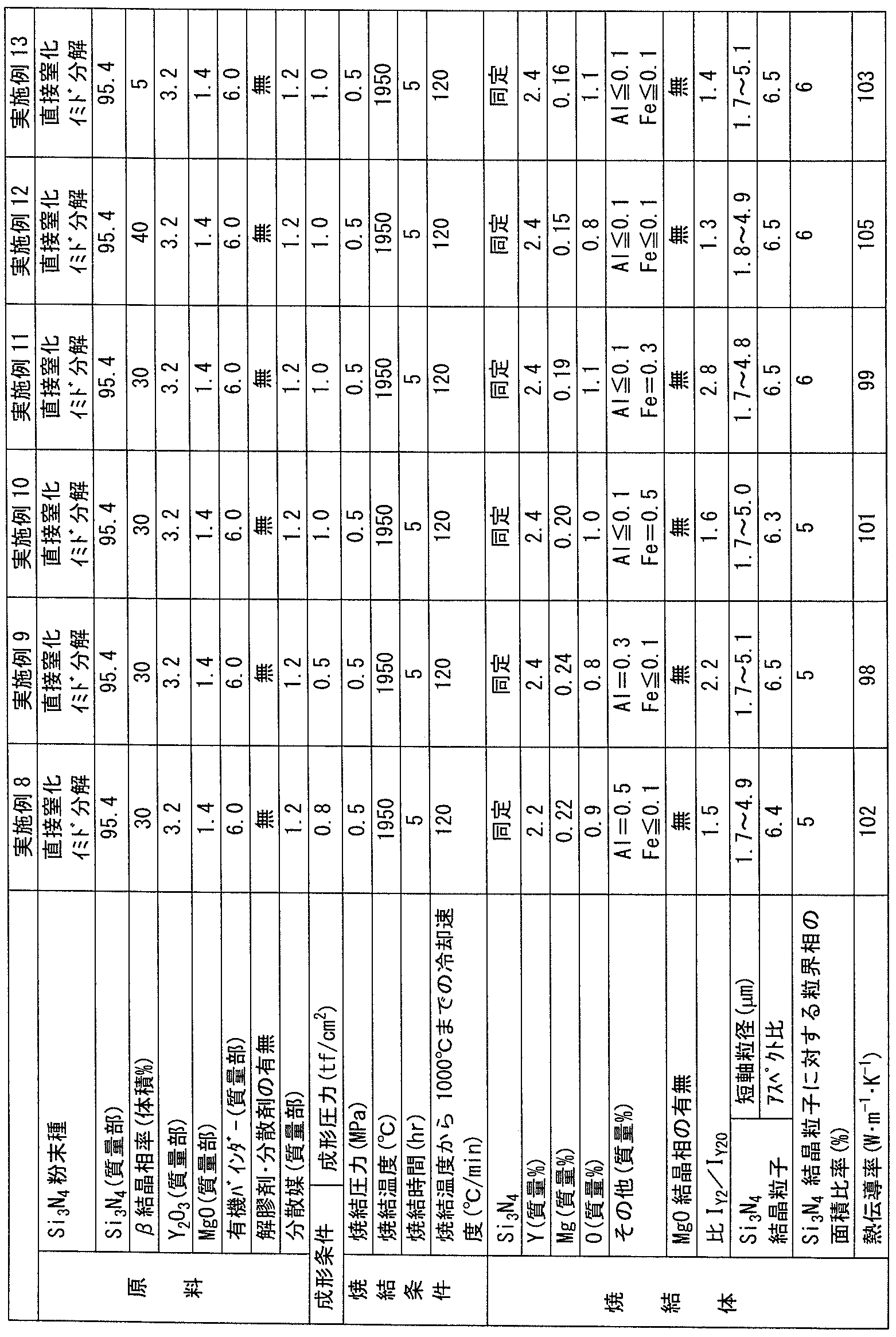
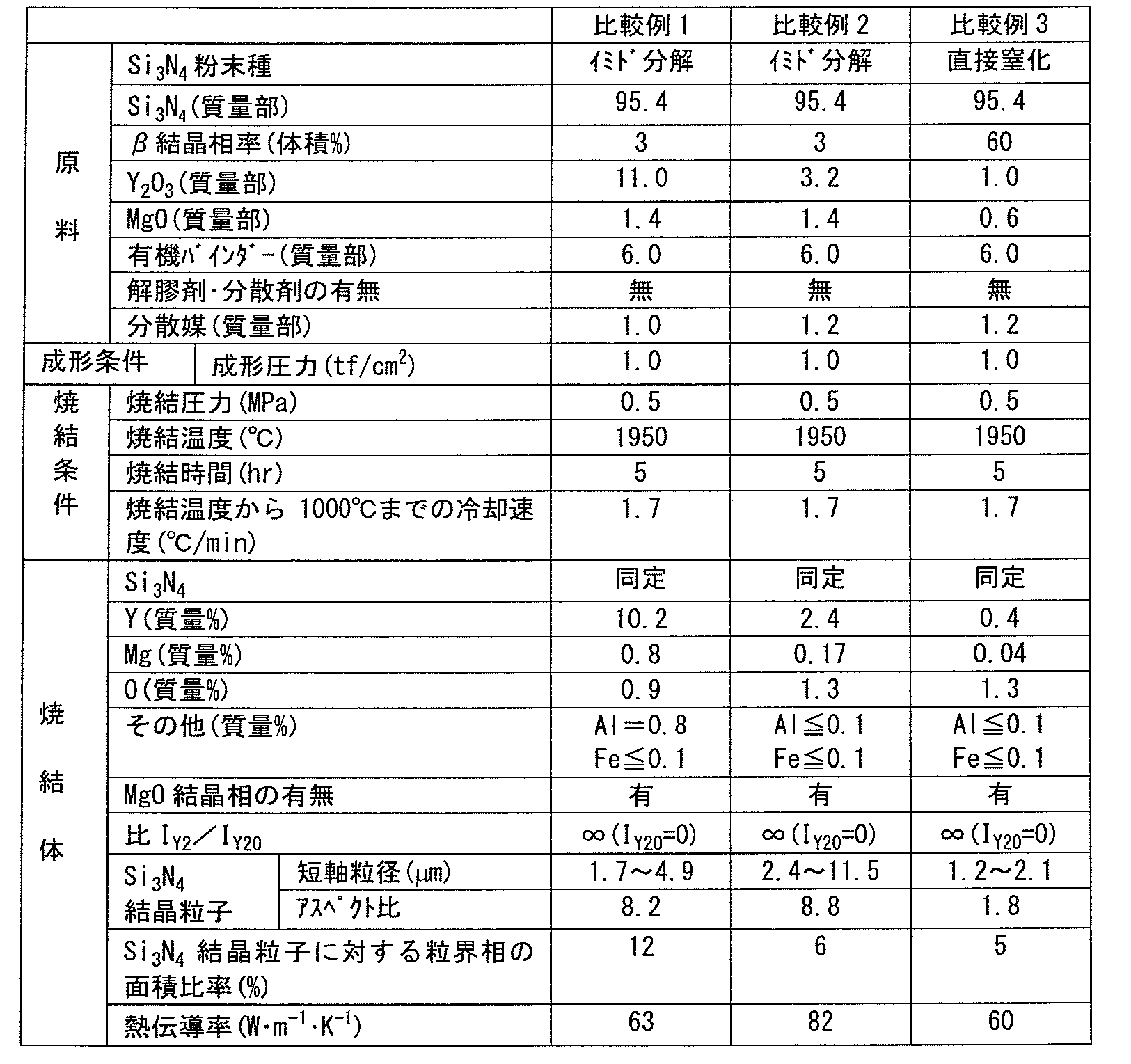
表1~2の実施例1~13に示すように、窒化ケイ素、イットリウム、マグネシウムおよび酸素を含み、複数の窒化ケイ素結晶粒子と窒化ケイ素結晶粒子以外の部分である粒界相とを含み、粒界相はY20N4Si12O48結晶相あるいはY20N4Si12O48結晶相およびY2Si3N3O4結晶相を含み、Y20N4Si12O48結晶相の(112)面に起因するX線回折ピークの強度IY20に対するY2Si3N3O4結晶相の(211)面に起因するX線回折ピークの強度IY2の比IY2/IY20が0以上3.0以下である窒化ケイ素焼結体は、95W・m-1・K-1以上の高い熱伝導率を示した。これに対して、表3の比較例1~7に示すように、Y20N4Si12O48結晶相の(112)面に起因するX線回折ピークの強度IY20が0となるためY20N4Si12O48結晶相の(112)面に起因するX線回折ピークの強度IY20に対するY2Si3N3O4結晶相の(211)面に起因するX線回折ピークの強度IY2の比IY2/IY20が∞(無限大)となって3.0よりも大きい窒化ケイ素焼結体は、95W・m-1・K-1未満の低い高い熱伝導率を示すに留まった。
今回開示された実施の形態および実施例はすべての点で例示であって制限的なものではないと考えられるべきである。本発明の範囲は上記した説明ではなくて請求の範囲によって示され、請求の範囲と均等の意味および範囲内でのすべての変更が含まれることが意図される。
Claims (7)
- 窒化ケイ素、イットリウム、マグネシウムおよび酸素を含む窒化ケイ素焼結体であり、
前記窒化ケイ素焼結体は、複数の窒化ケイ素結晶粒子と、前記窒化ケイ素結晶粒子以外の部分である粒界相と、を含み、
前記粒界相は、Y20N4Si12O48結晶相、あるいは、Y20N4Si12O48結晶相およびY2Si3N3O4結晶相、を含み、
前記Y20N4Si12O48結晶相の(112)面に起因するX線回折ピークの強度に対する前記Y2Si3N3O4結晶相の(211)面に起因するX線回折ピークの強度の比が0以上3.0以下である窒化ケイ素焼結体。 - 前記窒化ケイ素焼結体に含まれる複数の前記窒化ケイ素結晶粒子は、短軸粒径が1.7μm以上10.5μm以下であり、前記短軸粒径に対する長軸粒径の比であるアスペクト比が2.0以上7.7以下である、請求項1に記載の窒化ケイ素焼結体。
- ケイ素、イットリウムおよびマグネシウム以外の各種の不純物金属元素の含有率が各々0.5質量%以下である請求項1または請求項2に記載の窒化ケイ素焼結体。
- 酸化マグネシウム結晶相が存在しない請求項1から請求項3のいずれか1項に記載の窒化ケイ素焼結体。
- 熱伝導率が95W・m-1・K-1以上である請求項1から請求項4のいずれか1項に記載の窒化ケイ素焼結体。
- 前記窒化ケイ素焼結体の任意に特定される断面における前記窒化ケイ素結晶粒子に対する前記粒界相の面積比率が10%以下である請求項1から請求項5のいずれか1項に記載の窒化ケイ素焼結体。
- 請求項1から請求項6のいずれか1項に記載の窒化ケイ素焼結体の製造方法であって、原料の窒化ケイ素粉末のβ結晶相率を5質量%以上40質量%以下とする窒化ケイ素焼結体の製造方法。
Priority Applications (1)
| Application Number | Priority Date | Filing Date | Title |
|---|---|---|---|
| JP2017529867A JPWO2017014168A1 (ja) | 2015-07-21 | 2016-07-15 | 窒化ケイ素焼結体およびその製造方法 |
Applications Claiming Priority (2)
| Application Number | Priority Date | Filing Date | Title |
|---|---|---|---|
| JP2015-143716 | 2015-07-21 | ||
| JP2015143716 | 2015-07-21 |
Publications (2)
| Publication Number | Publication Date |
|---|---|
| WO2017014168A1 true WO2017014168A1 (ja) | 2017-01-26 |
| WO2017014168A9 WO2017014168A9 (ja) | 2017-04-27 |
Family
ID=57834804
Family Applications (1)
| Application Number | Title | Priority Date | Filing Date |
|---|---|---|---|
| PCT/JP2016/070927 Ceased WO2017014168A1 (ja) | 2015-07-21 | 2016-07-15 | 窒化ケイ素焼結体およびその製造方法 |
Country Status (3)
| Country | Link |
|---|---|
| JP (1) | JPWO2017014168A1 (ja) |
| TW (1) | TW201714857A (ja) |
| WO (1) | WO2017014168A1 (ja) |
Cited By (4)
| Publication number | Priority date | Publication date | Assignee | Title |
|---|---|---|---|---|
| WO2021053857A1 (en) | 2019-09-17 | 2021-03-25 | Kabushiki Kaisha Toshiba | Structure and bonded body |
| CN113636844A (zh) * | 2021-08-25 | 2021-11-12 | 北京科技大学 | 一种两步烧结制备高强高导热氮化硅陶瓷的方法 |
| US11355416B2 (en) | 2020-03-19 | 2022-06-07 | Kabushiki Kaisha Toshiba | Structure and joined composite |
| CN115667184A (zh) * | 2020-05-20 | 2023-01-31 | 株式会社东芝 | 氮化硅烧结体及采用其的耐磨损性部件以及氮化硅烧结体的制造方法 |
Citations (5)
| Publication number | Priority date | Publication date | Assignee | Title |
|---|---|---|---|---|
| JPS62197356A (ja) * | 1986-02-25 | 1987-09-01 | 日本碍子株式会社 | 窒化珪素焼結体の製造方法 |
| JPS63100066A (ja) * | 1986-06-02 | 1988-05-02 | トヨタ自動車株式会社 | 窒化ケイ素焼結体の製造方法 |
| JPS63100067A (ja) * | 1986-06-12 | 1988-05-02 | 日本碍子株式会社 | 窒化珪素焼結体およびその製造法 |
| JP2006096661A (ja) * | 2005-12-26 | 2006-04-13 | Hitachi Metals Ltd | 窒化ケイ素質焼結体およびそれを用いた回路基板。 |
| WO2006118003A1 (ja) * | 2005-04-28 | 2006-11-09 | Hitachi Metals, Ltd. | 窒化珪素基板、その製造方法、それを用いた窒化珪素配線基板及び半導体モジュール |
-
2016
- 2016-07-15 JP JP2017529867A patent/JPWO2017014168A1/ja active Pending
- 2016-07-15 TW TW105122474A patent/TW201714857A/zh unknown
- 2016-07-15 WO PCT/JP2016/070927 patent/WO2017014168A1/ja not_active Ceased
Patent Citations (5)
| Publication number | Priority date | Publication date | Assignee | Title |
|---|---|---|---|---|
| JPS62197356A (ja) * | 1986-02-25 | 1987-09-01 | 日本碍子株式会社 | 窒化珪素焼結体の製造方法 |
| JPS63100066A (ja) * | 1986-06-02 | 1988-05-02 | トヨタ自動車株式会社 | 窒化ケイ素焼結体の製造方法 |
| JPS63100067A (ja) * | 1986-06-12 | 1988-05-02 | 日本碍子株式会社 | 窒化珪素焼結体およびその製造法 |
| WO2006118003A1 (ja) * | 2005-04-28 | 2006-11-09 | Hitachi Metals, Ltd. | 窒化珪素基板、その製造方法、それを用いた窒化珪素配線基板及び半導体モジュール |
| JP2006096661A (ja) * | 2005-12-26 | 2006-04-13 | Hitachi Metals Ltd | 窒化ケイ素質焼結体およびそれを用いた回路基板。 |
Non-Patent Citations (3)
| Title |
|---|
| DAIJI NAKATA ET AL.: "RE(RE=Y,Gd,Nd,La)-Mg-Si- O-N Kei Yutaichu ni Okeru beta-Chikka Keiso no Kessho Seicho", JOURNAL OF THE JAPAN INSTITUTE OF METALS, vol. 69, no. 8, 20 August 2005 (2005-08-20), pages 719 - 722 * |
| JIANG, X ET AL.: "Si3N4 materials fabricated from powders with very high fraction of a phase", CERAM ENG SCI PROC, vol. 19, no. 3, 1998, pages 517 - 522, XP055347553 * |
| LEE,BYONG-TAEK ET AL.: "Effect of sintering additives on the nitridation behavior of reaction-bonded silicon nitride", MATERIALS SCIENCE AND ENGINEERING, vol. A364, no. 1 / 2, 15 January 2004 (2004-01-15), pages 126 - 131, XP055347551 * |
Cited By (9)
| Publication number | Priority date | Publication date | Assignee | Title |
|---|---|---|---|---|
| WO2021053857A1 (en) | 2019-09-17 | 2021-03-25 | Kabushiki Kaisha Toshiba | Structure and bonded body |
| JP2021046329A (ja) * | 2019-09-17 | 2021-03-25 | 株式会社東芝 | 構造体及び接合体 |
| JP7313105B2 (ja) | 2019-09-17 | 2023-07-24 | 株式会社東芝 | 構造体及び接合体 |
| US12308301B2 (en) | 2019-09-17 | 2025-05-20 | Kabushiki Kaisha Toshiba | Structure and bonded body |
| US11355416B2 (en) | 2020-03-19 | 2022-06-07 | Kabushiki Kaisha Toshiba | Structure and joined composite |
| CN115667184A (zh) * | 2020-05-20 | 2023-01-31 | 株式会社东芝 | 氮化硅烧结体及采用其的耐磨损性部件以及氮化硅烧结体的制造方法 |
| CN115667184B (zh) * | 2020-05-20 | 2024-05-03 | 株式会社东芝 | 氮化硅烧结体及采用其的耐磨损性部件以及氮化硅烧结体的制造方法 |
| CN113636844A (zh) * | 2021-08-25 | 2021-11-12 | 北京科技大学 | 一种两步烧结制备高强高导热氮化硅陶瓷的方法 |
| CN113636844B (zh) * | 2021-08-25 | 2022-11-18 | 北京科技大学 | 一种两步烧结制备高强高导热氮化硅陶瓷的方法 |
Also Published As
| Publication number | Publication date |
|---|---|
| TW201714857A (zh) | 2017-05-01 |
| WO2017014168A9 (ja) | 2017-04-27 |
| JPWO2017014168A1 (ja) | 2018-06-14 |
Similar Documents
| Publication | Publication Date | Title |
|---|---|---|
| TWI589546B (zh) | Sintered body | |
| WO2017014169A1 (ja) | 窒化ケイ素焼結体 | |
| US8158544B2 (en) | Yttria sintered body and component used for plasma processing apparatus | |
| JP7201103B2 (ja) | 板状の窒化ケイ素質焼結体およびその製造方法 | |
| ES2588772T3 (es) | Método para confeccionar un producto cerámico denso a base de SiC | |
| US20080283499A1 (en) | Corrosion-Resistant Member, Treatment Apparatus and Sample Treatment Method Using the Member, and Method for Manufacture of Corrosion-Resistant Member | |
| WO2017014168A9 (ja) | 窒化ケイ素焼結体およびその製造方法 | |
| TW201605763A (zh) | 氮化矽粉末、氮化矽燒結體及電路基板、以及氮化矽粉末之製造方法 | |
| WO2014002580A1 (ja) | 溶射材料及びその製造方法 | |
| EP4495065A1 (en) | Silicon nitride powder and method for producing silicon nitride sintered body | |
| JP3565425B2 (ja) | 窒化ケイ素質粉末の製造方法および窒化ケイ素質焼結体の製造方法 | |
| JP2004262756A (ja) | 窒化ケイ素質粉末、窒化ケイ素質焼結体及びこれを用いた電子部品用回路基板 | |
| JP2025157614A (ja) | 窒化ケイ素焼結体の製造方法 | |
| JP2017518253A (ja) | 透光性金属フッ化物セラミック | |
| WO2025028388A1 (ja) | 窒化ケイ素焼結体 | |
| TWI884245B (zh) | 氮化矽粉末、以及氮化矽燒結體之製造方法 | |
| JP2018024548A (ja) | 窒化ケイ素焼結体およびその製造方法 | |
| Lemański et al. | Spectroscopic and structural properties of MgAl2O4: Nd3+ nanopowders and ceramics | |
| Sidorowicz et al. | Precipitation of Tm2O3 nanopowders for application in reactive sintering of Tm: YAG | |
| TWI725685B (zh) | 燒結體 | |
| Kamran | Mn (II) ions assisted near-infrared single-mode lasing from an individual Mn-doped CdS nanobelts | |
| JP7857389B2 (ja) | 窒化ケイ素焼結体、絶縁回路基板、および半導体装置 | |
| JP2018024547A (ja) | 窒化ケイ素焼結体およびその製造方法 | |
| Sakajio et al. | FGM of YAG-MgO composites with enhanced thermal conductivity using spark plasma sintering | |
| JP6721793B2 (ja) | 窒化アルミニウム焼結体およびその製造方法 |
Legal Events
| Date | Code | Title | Description |
|---|---|---|---|
| ENP | Entry into the national phase |
Ref document number: 2017529867 Country of ref document: JP Kind code of ref document: A |
|
| 121 | Ep: the epo has been informed by wipo that ep was designated in this application |
Ref document number: 16827728 Country of ref document: EP Kind code of ref document: A1 |
|
| NENP | Non-entry into the national phase |
Ref country code: DE |
|
| 122 | Ep: pct application non-entry in european phase |
Ref document number: 16827728 Country of ref document: EP Kind code of ref document: A1 |