WO2017014101A1 - プーリ付き軸受 - Google Patents
プーリ付き軸受 Download PDFInfo
- Publication number
- WO2017014101A1 WO2017014101A1 PCT/JP2016/070521 JP2016070521W WO2017014101A1 WO 2017014101 A1 WO2017014101 A1 WO 2017014101A1 JP 2016070521 W JP2016070521 W JP 2016070521W WO 2017014101 A1 WO2017014101 A1 WO 2017014101A1
- Authority
- WO
- WIPO (PCT)
- Prior art keywords
- bearing
- pulley
- dust cover
- water
- rolling bearing
- Prior art date
- Legal status (The legal status is an assumption and is not a legal conclusion. Google has not performed a legal analysis and makes no representation as to the accuracy of the status listed.)
- Ceased
Links
Images

Classifications
-
- F—MECHANICAL ENGINEERING; LIGHTING; HEATING; WEAPONS; BLASTING
- F16—ENGINEERING ELEMENTS AND UNITS; GENERAL MEASURES FOR PRODUCING AND MAINTAINING EFFECTIVE FUNCTIONING OF MACHINES OR INSTALLATIONS; THERMAL INSULATION IN GENERAL
- F16C—SHAFTS; FLEXIBLE SHAFTS; ELEMENTS OR CRANKSHAFT MECHANISMS; ROTARY BODIES OTHER THAN GEARING ELEMENTS; BEARINGS
- F16C33/00—Parts of bearings; Special methods for making bearings or parts thereof
- F16C33/72—Sealings
- F16C33/76—Sealings of ball or roller bearings
-
- F—MECHANICAL ENGINEERING; LIGHTING; HEATING; WEAPONS; BLASTING
- F16—ENGINEERING ELEMENTS AND UNITS; GENERAL MEASURES FOR PRODUCING AND MAINTAINING EFFECTIVE FUNCTIONING OF MACHINES OR INSTALLATIONS; THERMAL INSULATION IN GENERAL
- F16C—SHAFTS; FLEXIBLE SHAFTS; ELEMENTS OR CRANKSHAFT MECHANISMS; ROTARY BODIES OTHER THAN GEARING ELEMENTS; BEARINGS
- F16C41/00—Other accessories, e.g. devices integrated in the bearing not relating to the bearing function as such
-
- F—MECHANICAL ENGINEERING; LIGHTING; HEATING; WEAPONS; BLASTING
- F16—ENGINEERING ELEMENTS AND UNITS; GENERAL MEASURES FOR PRODUCING AND MAINTAINING EFFECTIVE FUNCTIONING OF MACHINES OR INSTALLATIONS; THERMAL INSULATION IN GENERAL
- F16H—GEARING
- F16H55/00—Elements with teeth or friction surfaces for conveying motion; Worms, pulleys or sheaves for gearing mechanisms
- F16H55/32—Friction members
- F16H55/36—Pulleys
-
- F—MECHANICAL ENGINEERING; LIGHTING; HEATING; WEAPONS; BLASTING
- F16—ENGINEERING ELEMENTS AND UNITS; GENERAL MEASURES FOR PRODUCING AND MAINTAINING EFFECTIVE FUNCTIONING OF MACHINES OR INSTALLATIONS; THERMAL INSULATION IN GENERAL
- F16C—SHAFTS; FLEXIBLE SHAFTS; ELEMENTS OR CRANKSHAFT MECHANISMS; ROTARY BODIES OTHER THAN GEARING ELEMENTS; BEARINGS
- F16C19/00—Bearings with rolling contact, for exclusively rotary movement
- F16C19/02—Bearings with rolling contact, for exclusively rotary movement with bearing balls essentially of the same size in one or more circular rows
- F16C19/04—Bearings with rolling contact, for exclusively rotary movement with bearing balls essentially of the same size in one or more circular rows for radial load mainly
- F16C19/06—Bearings with rolling contact, for exclusively rotary movement with bearing balls essentially of the same size in one or more circular rows for radial load mainly with a single row or balls
Definitions
- This invention relates to a bearing with a pulley in an automobile engine.
- belt movement is guided by idler pulleys, or tension pulleys are pressed against the belt by hydraulic auto tensioners to absorb belt tension fluctuations.
- the tension is kept constant.
- a bearing with a seal that prevents the entry of foreign matter into the bearing by a seal is generally used for a bearing that rotatably supports the pulley. Used for.
- An object of the present invention is to provide a bearing with a pulley that can smoothly discharge water droplets that have entered the dust cover.
- a rolling bearing with a seal a pulley having a boss portion in which the rolling bearing is incorporated in an inner peripheral portion, and dust covers provided on both sides of the rolling bearing are provided.
- a configuration is adopted in which a water repellent process is applied to the inner surface of the dust cover facing the rolling bearing.
- the gap amount is preferably 1.5 mm or less.
- the wetting angle of the water droplet when it adheres to the water-repellent surface of the dust cover is smaller than necessary, the water droplet spreads outward and becomes an expanded wet state, and the adhesion of the water droplet to the dust cover increases. Therefore, the wetting angle is preferably 90 ° or more.
- the wetting angle is the angle at which the water droplet surface forms the surface of the dust cover at the boundary line where the three layers contact when water droplets adhere to the dust cover and the surface of the dust cover is in contact with water droplets and gas. (Contact angle).
- the bearing pulley surface facing the water repellent surface of the dust cover is subjected to water repellent treatment within a range not exceeding the wetting angle of the dust cover.
- the water repellent finish is also applied to the bearing pulley surface, so that water droplets entering between the facing portions of the dust cover and the rolling bearing can be discharged more smoothly.
- the water repellent treatment is applied to the inner side surface of the dust cover that covers the side surface of the rolling bearing, so that water droplets that have entered between the facing portions of the rolling bearing and the dust cover are caused by the rotation of the rolling bearing. Since it becomes easy to receive the influence of a centrifugal force, a water droplet can be discharged
- the bearing with pulley includes a rolling bearing 10, a pulley 30 that is rotatably supported by the rolling bearing 10, and a pair of dust covers 40 and 41 provided on both sides of the rolling bearing 10. have.
- a plurality of balls 15 are assembled between a raceway groove 12 formed on the inner diameter surface of the outer ring 11 and a raceway groove 14 formed on the outer diameter surface of the inner ring 13, and the balls 15 are held by a cage 16.
- the bearing space formed between the outer ring 11 and the inner ring 13 is a ball bearing with a seal in which both ends of the bearing space are sealed with a pair of seals 17.
- the seal 17 is supported at the outer peripheral portion by a seal mounting groove 18 formed at the end of the inner surface of the outer ring 11, and the inner peripheral portion has an inner portion as shown in FIG.
- An inward lip 19a and an outward lip 19b are formed, and the inward lip 19a elastically contacts the inner wall 20a of the seal groove 20 formed at the end of the outer diameter surface of the inner ring 13, while the outward lip 19b
- the space between the inner ring 13 and the inner ring 13 is sealed by elastic contact with a cylindrical land portion 21 formed outside the seal groove 20.
- the rolling bearing 10 with a seal is not limited to a ball bearing.
- a cylindrical roller bearing may be used.
- each of the inward lip 19a and the outward lip 19b is elastically brought into contact with the corresponding surface, but only one of the inward lip 19a and the outward lip 19b is supported. You may make it make elastic contact with respect to.
- the inner ring 13 of the roller bearing 10 with seal is supported in a non-rotating manner by screwing a bolt 22 inserted inside thereof into a screw hole 24 formed in the shaft end surface of the pulley shaft 23. .
- the bolt 22 is provided with a large-diameter shaft portion 22b at the end portion of the screw shaft 22a, a flange 22c at the end portion of the large-diameter shaft portion 22b, and a head portion 22d at the end surface of the flange 22c.
- the large-diameter shaft portion 22b is fitted to the inner ring 13 of the rolling bearing 10, and the screw shaft 22a is screwed into the screw hole 24 of the pulley shaft 23 and tightened, whereby the inner ring 13 is connected to the flange 22c and the pulley shaft.
- the shaft end face 23 is clamped from both sides and fixed.
- the pulley 30 has a belt guide wheel 31 on the outer peripheral portion, an annular flange 32 is formed on the inner diameter surface of the belt guide wheel 31, and a boss portion 33 is provided on the inner diameter portion of the annular flange 32.
- an inward flange 34 is provided at one end of the boss portion 33, and an outer surface of the flange 34 is a tapered surface 35.
- the pulley 30 is a metal molded product here, but may be a metal turning product or a resin molded product.
- the belt guide wheel 31 is for a flat belt guide whose outer diameter surface is a cylindrical surface 31a, but is for a V belt guide having a plurality of V grooves formed on the outer diameter surface. There may be.
- the pulley 30 is rotatably supported by press-fitting the outer ring 11 of the rolling bearing 10 inside the boss portion 33, and the pulley 30 and the rolling bearing 10 are brought into contact with the inward flange 34 against the inside side surface of the outer ring 11. Relative axial positioning is assumed. In the positioning state, the outer surface of the boss 33 forms the same surface as the outer side surface of the outer ring 11.
- one of the outside dust covers 40 provided on the head 22 d side of the bolt 22 includes an inner ring portion 42 and its inner ring. It comprises an annular plate having an inclined part 43 provided continuously on the outer periphery of the part 42 and an outer ring part 44 provided continuously on the outer periphery of the inclined part 43.
- the outer diameter of the outer ring part 44 is a pulley.
- the outer diameter of the 30 boss portions 33 is the same.
- the one dust cover 40 has an inner ring portion 42 fixed between the flange 22c of the bolt 22 and the inner ring 13 from both sides. At this time, the dust cover 40 is attached so that the inclined portion 43 bulges outward, and a gap 45 is provided between the outer ring portion 44 and the outer surface of the boss portion 33.
- the gap amount in the axial direction of the gap 45 and [delta] 1 is a 1.5mm or less.
- the other dust cover 41 on the screw shaft portion 22 a side of the bolt 22, that is, on the shaft end surface side of the pulley shaft 23, is connected to the inner ring portion 46 and the outer periphery of the inner ring portion 46. It comprises an annular plate having two stepped inclined portions 47 inclined in the same direction and an outer ring portion 48 connected to the outer periphery of the stepped inclined portion 47.
- the diameter is the same as the outer diameter of the boss portion 33 of the pulley 30.
- the other dust cover 41 is fixed with the inner ring portion 46 sandwiched from both sides by the inner ring 13 and the shaft end surface of the pulley shaft 23. At this time, the dust cover 41 is attached so that the stepped inclined portion 47 bulges outward, and a gap 49 is provided between the outer ring portion 48 and the outer surface of the boss portion 33.
- the gap amount ⁇ 1 in the axial direction of the gap 49 has the same size as the gap amount ⁇ 1 in the axial direction of the gap 45 formed between the outer ring portion 44 of one dust cover 40 and the outer surface of the boss portion 33. ing.
- Each of the pair of dust covers 40 and 41 is made of a press-formed product of a steel plate, and the inner side surface facing the side surface of the rolling bearing 10 is water-repellent processed, and as shown in FIGS. 2 and 3, the water-repellent layer 50 Is provided.
- a primer is attached to the surface of the dust covers 40, 41, and a highly water repellent coating material such as Teflon is applied on the surface to a thickness of about 20-30 ⁇ m and baked at a high temperature.
- a highly water repellent coating material such as Teflon
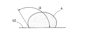
- FIG. 4 shows a state in which water droplets A adhere to the surface of the water-repellent layer 50, and the wetting angle ⁇ of the water droplets A is 90 ° or more.
- the wetting angle means that when the water droplet A adheres to the water repellent layer 50 and the surface of the water repellent layer 50 is in contact with the water droplet A and the gas, the water droplet surface repels at the boundary line where these three layers contact. A contact angle formed with the surface of the water layer 50.
- the pulley-equipped bearing shown in the embodiment has the above-described structure, and the pulley-equipped bearing is used for moving guidance of an automobile accessory driving belt or for adjusting belt tension.
- gaps 45, 49 formed between the dust covers 40, 41 and the boss portion 33 in the pulley 30 facing each other in the axial direction have an extremely small gap of 1.5 mm or less, the gap 45 , 49, almost no water drops enter the inside. However, as long as there are gaps 45 and 49, it is not possible to completely prevent water droplets from entering.
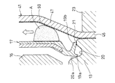
- FIG. 2 shows a state in which water droplets A have entered between the dust cover 41 on the inside side and the seal 17 of the rolling bearing 10.
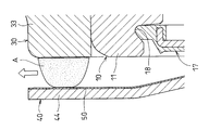
- FIG. 3 shows a state in which the water droplet A has entered between the opposing surfaces of the dust cover 40 on the outside side and the boss portion 33 of the pulley 30.
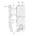
- FIG. 5 shows a state in which water droplets A have entered between the facing portions of the dust cover 40 and the boss portion 33 of the pulley 30 that have not been subjected to water repellent processing.
- the water droplet A adheres to each of the inner surface of the dust cover 40 and the side surface of the boss portion 33.
- each of the dust cover 40 and the pulley 30 is made of metal and has the same surface roughness, the adhesion force of the water droplet A to the inner surface of the dust cover 40 and the adhesion force of the water droplet A to the side surface of the boss portion 33 are substantially equal. It is said.
- the pulley 30 is rotated by the movement of the belt guided by the belt guide wheel 31 on the outer periphery thereof, but the dust cover 40 is formed by the inner ring 13 of the rolling bearing 10 and the flange 22c of the bolt 22 as shown in FIG. Since it is clamped from both sides and fixed, the adhesion force of the water droplet A to the dust cover 40 becomes resistance, and the water droplet A is less affected by the centrifugal force, and the water droplet A cannot be discharged well.
- the water droplet A since the water repellent layer 50 is provided on the inner surface of the dust cover 40, the water droplet A has a rounded surface on the dust cover 40 side and spreads on the surface on the boss portion 33 side. In an expanded wet state, the adhesion force of the water droplet A is large on the boss portion 33 side and small on the dust cover 40 side.
- the seal 17 is made of rubber, and the dust cover 41 has a water repellent layer 50 on the inner surface. Therefore, the water droplet A is rounded on the surface on the dust cover 41 side, and is in an expanded wet state with a spread on the surface on the boss portion 33 side, and the adhesion force of the water droplet A is large on the seal 17 side, It becomes small on the dust cover 41 side.
- the wetting angle ⁇ of the water droplet A with the water droplet A adhering to the surface of the water repellent layer 50 is set to 90 ° or more, the water droplet A that has entered can be discharged more effectively. it can.
- the bearing pulley surface (including the outer ring 11, the seal 17, and the seal groove 20) facing the water repellent surface of the dust covers 40, 41 is subjected to water repellent processing within a range not exceeding the wetting angle of the dust covers 40, 41. You may do it.
- the water droplet A that has entered can be more effectively discharged by applying water repellent treatment to the bearing pulley surface.
Landscapes
- Engineering & Computer Science (AREA)
- General Engineering & Computer Science (AREA)
- Mechanical Engineering (AREA)
- Sealing Of Bearings (AREA)
- Pulleys (AREA)
- Rolling Contact Bearings (AREA)
- Sealing Using Fluids, Sealing Without Contact, And Removal Of Oil (AREA)
- Sealing Devices (AREA)
Abstract
プーリ(30)を回転自在に支持するシール付き転がり軸受(10)の両側にダストカバー(40、41)を設け、そのダストカバー(40、41)のそれぞれ内側面に撥水加工を施して、ダストカバー(40、41)内に浸入する水滴(A)の、ダストカバー(40、41)に対する付着力の低減を図り、転がり軸受(10)の回転による遠心力の影響を受け易くして、水滴(A)が円滑に排出されるようにしたプーリ付き軸受である。
Description
この発明は、自動車エンジンにおけるプーリ付き軸受に関する。
オルタネータやコンプレッサ等の自動車補機を駆動するベルト伝動装置においては、アイドラプーリによってベルトの移動を案内し、あるいは、油圧式オートテンショナによりテンションプーリをベルトに押し付けてベルトの張力変動を吸収し、ベルト張力を一定に保つようにしている。
上記のようなアイドラプーリやテンションプーリは、外部に露出する組み付けであるため、そのプーリを回転自在に支持する軸受には、シールによって軸受内部への異物の侵入を防止するシール付き軸受が一般的に使用される。
しかし、シール付き軸受に組み込まれたシールのみで泥水などの異物の軸受内への侵入を防止する場合、異物との接触によってシールが損傷し易く、耐久性に問題があるため、シール付き軸受の両側にダストカバーを設けてシールの損傷を防止し、軸受のシール性の向上を図ることが行われている(下記特許文献1、2参照)。
ところで、特許文献1および2に記載されたプーリ付き軸受においては、シール付き軸受とダストカバーとの対向部間に形成された間隙が小さく、また、特許文献2に記載されたプーリ付き軸受においては、プーリの側面に環状の突条を設け、その突条によってシール付き軸受とダストカバーとの対向部間に形成された間隙を覆うようにしているため、上記間隙からダストカバー内に水滴が浸入することは少ないが、万一浸入すると、スムーズに排出することができない。
すなわち、シール付き軸受とダストカバーとの対向部間に形成された間隙内に水滴が浸入した場合、その水滴はシール付き軸受の側面とダストカバーの内側面の両方に付着する。このとき、ダストカバーは軸受の内輪に支持されて回転することがなく、そのダストカバー側の水滴の付着力が抵抗となって遠心力の影響を受けることが少なくなり、水滴を良好に排出することができない。
近年では、従来では考慮されていなかった悪路走行等の条件が増え、ダストカバーでの対策だけでは、軸受内部に異物の侵入が認められており、その結果としてプーリ付き軸受の耐水要求が高まってきている。
この発明の課題は、ダストカバー内に浸入した水滴を円滑に排出することができるようにしたプーリ付き軸受を提供することである。
上記の課題を解決するため、この発明においては、シール付き転がり軸受と、その転がり軸受が組み込まれたボス部を内周部に有するプーリと、前記転がり軸受の両側に設けられたダストカバーとを有してなり、前記ダストカバーによって前記転がり軸受の側面を覆うようにしたプーリ付き軸受において、前記ダストカバーの前記転がり軸受と対向する内側面に撥水加工を施した構成を採用したのである。
上記のように、ダストカバーの内側面に撥水加工を施すことにより、ダストカバーと転がり軸受の対向部間に万一水滴が浸入した場合、その水滴の付着力は転がり軸受側で大きく、ダストカバー側で小さいものとなり、転がり軸受の回転により、その転がり軸受と共に水滴が回転する。このため、水滴は負荷される遠心力により径方向外方に向けて移動して外部にスムーズに排出されることになる。
この発明に係るプーリ付き軸受において、ダストカバーの外周部に形成された外環部と転がり軸受の外輪側面との対向部間に形成される間隙の軸方向の間隙量が大きくなり過ぎると、異物が侵入し易くなるため、上記間隙量は1.5mm以下とするのがよい。
また、ダストカバーの撥水加工面に水滴が付着した際の水滴の濡れ角度が必要以上に小さい場合は、水滴が外方に拡がりをもって拡張濡れ状態となり、ダストカバーに対する水滴の付着力が大きくなって遠心力の影響を受けることが少なくなるため、上記濡れ角度は90°以上とすることが好ましい。
ここで、濡れ角度とは、ダストカバーに水滴が付着し、ダストカバーの表面が水滴および気体と接触しているとき、この3層が接触する境界線において水滴面がダストカバーの表面と成す角度(接触角)をいう。
この発明に係るプーリ付き軸受において、ダストカバーの撥水加工面と対向する軸受プーリ面にダストカバーの濡れ角度を超えない範囲で撥水加工を施すのがよい。このように、軸受プーリ面にも撥水加工を施すことによって、ダストカバーと転がり軸受の対向部間に浸入する水滴をより円滑に排出することができる。
この発明においては、上記のように、転がり軸受の側面を覆うダストカバーの内側面に撥水加工を施したことにより、転がり軸受とダストカバーの対向部間に浸入した水滴は転がり軸受の回転による遠心力の影響を受け易くなるため、水滴を円滑に排出することができる。
以下、この発明の実施の形態を図面に基づいて説明する。図1に示すように、プーリ付き軸受は、転がり軸受10と、その転がり軸受10によって回転自在に支持されたプーリ30と、上記転がり軸受10の両側に設けられた一対のダストカバー40、41とを有している。
転がり軸受10は、外輪11の内径面に形成された軌道溝12と、内輪13の外径面に形成された軌道溝14間に複数のボール15を組込み、そのボール15を保持器16で保持し、上記外輪11と内輪13の対向部間に形成された軸受空間の両端開口を一対のシール17で密閉したシール付きの玉軸受からなる。
ここで、シール17は、図3に示すように、外輪11の内径面端部に形成されたシール取付溝18で外周部が支持され、内周部には、図2に示すように、内向きリップ19aと外向きリップ19bが形成され、上記内向きリップ19aが内輪13の外径面の端部に形成されたシール溝20の内側壁20aに弾性接触し、一方、外向きリップ19bがシール溝20の外側に形成された円筒形のランド部21に弾性接触して、内輪13との間を密閉している。
なお、シール付き転がり軸受10は、玉軸受に限定されない。例えば、円筒ころ軸受であってもよい。
また、図2では、内向きリップ19aおよび外向きリップ19bのそれぞれを対応する面に対して弾性接触させるようにしたが、内向きリップ19aおよび外向きリップ19bのいずれか一方のみを対応する面に対して弾性接触させるようにしてもよい。
図1に示すように、シール付き転がり軸受10の内輪13は、その内側に挿入されたボルト22をプーリ軸23の軸端面に形成されたねじ孔24にねじ込むことによって非回転の支持とされる。
ここで、ボルト22は、ねじ軸22aの端部に大径軸部22bが設けられ、その大径軸部22bの端部にフランジ22cと、そのフランジ22cの端面に頭部22dが設けられた構成とされており、上記大径軸部22bが転がり軸受10の内輪13に嵌合され、プーリ軸23のねじ孔24にねじ軸22aをねじ込んで締め付けることによって、内輪13がフランジ22cとプーリ軸23の軸端面で両側から挟持されて固定とされる。
プーリ30は、外周部にベルト案内輪31を有し、そのベルト案内輪31の内径面に環状フランジ32が形成され、その環状フランジ32の内径部にボス部33が設けられている。また、ボス部33の一方の端部には内向きフランジ34が設けられ、そのフランジ34の外側面はテーパ面35とされている。
なお、プーリ30として、ここでは、金属の成形品としているが、金属の旋削加工品であってもよく、あるいは、樹脂の成形品であってもよい。
また、ベルト案内輪31として、ここでは、外径面が円筒面31aからなる平ベルト案内用のものを示したが、外径面に複数のV溝が形成されたVベルト案内用のものであってもよい。
プーリ30は、ボス部33の内側に転がり軸受10の外輪11が圧入されて回転自在に支持され、その外輪11のインサイド側の側面に対する内向きフランジ34の当接によってプーリ30と転がり軸受10の相対的な軸方向の位置決めとされている。その位置決め状態においてボス部33の外側面は外輪11のアウトサイド側の側面と同一面を形成している。
転がり軸受10の両側に設けられた一対のダストカバー40、41のうち、ボルト22の頭部22d側に設けられたアウトサイド側の一方のダストカバー40は、内環部42と、その内環部42の外周に連設された傾斜部43と、その傾斜部43の外周に連設された外環部44とを有してなる環状板からなり、上記外環部44の外径はプーリ30のボス部33の外径と同径とされている。
上記一方のダストカバー40は内環部42がボルト22のフランジ22cと内輪13とで両側から挟持されて固定とされている。このとき、ダストカバー40は、傾斜部43が外側方に膨出する取り付けとされて、外環部44とボス部33の外側面間に間隙45が設けられている。上記間隙45の軸方向の間隙量をδ1とすると、そのδ1は1.5mm以下とされている。
ボルト22のねじ軸部22a側、すなわち、プーリ軸23の軸端面側に設けられたインサイド側の他方のダストカバー41は、内環部46と、その内環部46の外周に連設された2段の同方向に傾斜する段付き傾斜部47と、その段付き傾斜部47の外周に連設された外環部48とを有してなる環状板からなり、上記外環部48の外径はプーリ30のボス部33の外径と同径とされている。
上記他方のダストカバー41は、内環部46が内輪13とプーリ軸23の軸端面とで両側から挟持されて固定とされている。このとき、ダストカバー41は、段付き傾斜部47が外側方に膨出する取り付けとされて、外環部48とボス部33の外側面間に間隙49が設けられている。上記間隙49の軸方向の間隙量δ1は、一方のダストカバー40の外環部44とボス部33の外側面間に形成された間隙45の軸方向の間隙量δ1と同じ大きさとされている。
一対のダストカバー40、41のそれぞれは、鋼板のプレス成形品からなり、転がり軸受10の側面と対向する内側面は撥水加工されて、図2および図3に示すように、撥水層50が設けられている。
撥水加工として、ここでは、ダストカバー40、41の表面にプライマを着け、その上にテフロン等の撥水性の高いコーティング材を厚さ20~30μm程度に塗布して高温で焼付けるようにしているが、これに限定されるものではない。
ここで、図4は、撥水層50の表面に水滴Aが付着した状態を示し、その水滴Aの濡れ角度αは90°以上とされている。ここで、濡れ角度とは、撥水層50に水滴Aが付着し、撥水層50の表面が水滴Aおよび気体と接触しているとき、この3層が接触する境界線において水滴面が撥水層50の表面と成す接触角をいう。
実施の形態で示すプーリ付き軸受は上記の構造からなり、そのプーリ付き軸受は、自動車補機駆動用ベルトの移動案内用として、あるいは、ベルトの張力調整用として用いられる。
上記のような使用では、外部に露出する取り付けであるため、悪路での走行時、飛散する泥水がプーリ30内に侵入してくる場合が多い。このとき、プーリ30を回転自在に支持する転がり軸受10の両側にはダストカバー40、41が設けられているため、そのダストカバー40、41によって転がり軸受10のシール17に対する泥水等の異物の衝突を避けることができ、シール17の損傷を防止することができる。
また、ダストカバー40、41とプーリ30におけるボス部33の対向面間に形成された間隙45、49の軸方向の間隙量は1.5mm以下とされた極めて小さなものであるため、その間隙45、49から内部に水滴が浸入することは殆どない。しかし、間隙45、49がある以上、水滴の浸入を完全に防止することはできない。
図2は、インサイド側のダストカバー41と転がり軸受10のシール17間に水滴Aが浸入した状態を示す。また、図3は、アウトサイド側のダストカバー40とプーリ30のボス部33の対向面間に水滴Aが浸入した状態を示す。
ここで、ダストカバー40、41のそれぞれの内側面は撥水加工が施されて撥水層50が設けられているため、水滴Aをスムーズに排出することができる。その水滴Aの排出について以下に説明する。
図5は、撥水加工が施されていないダストカバー40とプーリ30のボス部33の対向部間に水滴Aが浸入した状態を示す。図5に示すように、ダストカバー40の内側面に撥水加工が施されていないと、水滴Aはダストカバー40の内側面とボス部33の側面のそれぞれに付着する。ダストカバー40およびプーリ30のそれぞれが金属で形成されて表面粗さが同じである場合、ダストカバー40の内側面に対する水滴Aの付着力とボス部33の側面に対する水滴Aの付着力は略同等とされる。
ここで、プーリ30は、その外周のベルト案内輪31で案内されるベルトの移動によって回転するが、ダストカバー40は図1に示すように、転がり軸受10の内輪13とボルト22のフランジ22cで両側から挟持されて固定されているため、ダストカバー40に対する水滴Aの付着力が抵抗となって、水滴Aは遠心力の影響を受けることが少なく、水滴Aを良好に排出することができない。
しかし、実施の形態においては、ダストカバー40の内側面には撥水層50を設けているため、水滴Aはダストカバー40側で表面に丸みを帯び、ボス部33側で表面に拡がりを持つ拡張濡れ状態となって、水滴Aの付着力がボス部33側で大きく、ダストカバー40側で小さいものとなる。
このため、プーリ30が回転することにより、そのプーリ30のボス部33と共に水滴Aが回転する。このため、水滴Aは負荷される遠心力により、図3の矢印で示すように、径方向外方に向けて移動して外部にスムーズに排出されることになる。
一方、図2に示すように、インサイド側のダストカバー41と転がり軸受10のシール17間に水滴Aが浸入した場合、シール17はゴム製であり、ダストカバー41は内側面に撥水層50が設けられているため、水滴Aはダストカバー41側で表面に丸みを帯び、ボス部33側で表面に拡がりを持つ拡張濡れ状態となって、水滴Aの付着力はシール17側で大きく、ダストカバー41側で小さいものとなる。
このため、プーリ30が回転することにより、転がり軸受10の外輪11と共にシール17が回転し、そのシール17と共に水滴Aが回転する。このため、水滴Aは負荷される遠心力により、図2の矢印で示すように、径方向外方に向けて移動して外部にスムーズに排出されることになる。
図4に示すように、撥水層50の表面に水滴Aが付着した状態での水滴Aの濡れ角度αを90°以上とすることにより、浸入した水滴Aをより効果的に排出することができる。
なお、ダストカバー40、41の撥水加工面と対向する軸受プーリ面(外輪11、シール17、シール溝20を含む)にダストカバー40,41の濡れ角度を超えない範囲で撥水加工を施すようにしてもよい。軸受プーリ面にも撥水加工を施すことによって浸入した水滴Aをより効果的に排出することができる。
10 転がり軸受
30 プーリ
33 ボス部
40 ダストカバー
41 ダストカバー
44 外環部
48 外環部
50 撥水層
30 プーリ
33 ボス部
40 ダストカバー
41 ダストカバー
44 外環部
48 外環部
50 撥水層
Claims (4)
- シール付き転がり軸受(10)と、その転がり軸受(10)が組み込まれたボス部(33)を内周部に有するプーリ(30)と、前記転がり軸受(10)の両側に設けられたダストカバー(40、41)とを有してなり、前記ダストカバー(40、41)によって前記転がり軸受(10)の側面を覆うようにしたプーリ付き軸受において、
前記ダストカバー(40、41)の前記転がり軸受と対向する内側面に撥水加工を施したことを特徴とするプーリ付き軸受。 - 前記ダストカバー(40、41)の外周部に形成された外環部(44、48)と前記転がり軸受(10)の外輪側面との対向部間に形成される間隙(45、49)の軸方向の間隙量を1.5mm以下とした請求項1に記載のプーリ付き軸受。
- 前記ダストカバー(40、41)の撥水加工面に水滴が付着した際の水滴の濡れ角度を90°以上とした請求項1又は2に記載のプーリ付き軸受。
- 前記ダストカバー(40、41)の撥水加工面と対向する軸受プーリ面にダストカバー(40、41)の濡れ角度を超えない範囲で撥水加工を施した請求項1乃至3のいずれか1項に記載のプーリ付き軸受。
Priority Applications (1)
| Application Number | Priority Date | Filing Date | Title |
|---|---|---|---|
| CN201680039489.0A CN107850122B (zh) | 2015-07-22 | 2016-07-12 | 带有带轮的轴承 |
Applications Claiming Priority (2)
| Application Number | Priority Date | Filing Date | Title |
|---|---|---|---|
| JP2015-145029 | 2015-07-22 | ||
| JP2015145029A JP6602583B2 (ja) | 2015-07-22 | 2015-07-22 | プーリ付き軸受 |
Publications (1)
| Publication Number | Publication Date |
|---|---|
| WO2017014101A1 true WO2017014101A1 (ja) | 2017-01-26 |
Family
ID=57833997
Family Applications (1)
| Application Number | Title | Priority Date | Filing Date |
|---|---|---|---|
| PCT/JP2016/070521 Ceased WO2017014101A1 (ja) | 2015-07-22 | 2016-07-12 | プーリ付き軸受 |
Country Status (3)
| Country | Link |
|---|---|
| JP (1) | JP6602583B2 (ja) |
| CN (1) | CN107850122B (ja) |
| WO (1) | WO2017014101A1 (ja) |
Cited By (2)
| Publication number | Priority date | Publication date | Assignee | Title |
|---|---|---|---|---|
| WO2024190791A1 (ja) * | 2023-03-14 | 2024-09-19 | 三ツ星ベルト株式会社 | アイドラプーリ |
| JP7557642B1 (ja) | 2023-03-14 | 2024-09-27 | 三ツ星ベルト株式会社 | アイドラプーリ |
Families Citing this family (2)
| Publication number | Priority date | Publication date | Assignee | Title |
|---|---|---|---|---|
| CN114215845A (zh) * | 2021-12-24 | 2022-03-22 | 中山市盈科轴承制造有限公司 | 一种轴承密封结构 |
| CN116292828A (zh) * | 2023-04-13 | 2023-06-23 | 江苏爱尔特实业有限公司 | 一种惰轮结构 |
Citations (9)
| Publication number | Priority date | Publication date | Assignee | Title |
|---|---|---|---|---|
| JP2002303330A (ja) * | 2001-02-05 | 2002-10-18 | Nsk Ltd | 転がり軸受 |
| JP2008256197A (ja) * | 2007-03-14 | 2008-10-23 | Nsk Ltd | 転がり軸受及びその製造方法 |
| JP2009074480A (ja) * | 2007-09-21 | 2009-04-09 | Jtekt Corp | ウォータポンプ |
| JP2009174683A (ja) * | 2008-01-28 | 2009-08-06 | Ntn Corp | 樹脂プーリ付き軸受 |
| JP2011117475A (ja) * | 2009-12-01 | 2011-06-16 | Ntn Corp | 車輪用軸受装置 |
| JP2012167818A (ja) * | 2012-04-18 | 2012-09-06 | Mitsubishi Electric Corp | 電動機 |
| JP2012167809A (ja) * | 2011-01-27 | 2012-09-06 | Nsk Ltd | 転がり軸受 |
| JP2014131482A (ja) * | 2014-03-27 | 2014-07-10 | Mitsubishi Electric Corp | 電動機 |
| WO2015005416A1 (ja) * | 2013-07-11 | 2015-01-15 | Ntn株式会社 | アイドラプーリの支持装置 |
Family Cites Families (3)
| Publication number | Priority date | Publication date | Assignee | Title |
|---|---|---|---|---|
| JP3903506B2 (ja) * | 1996-12-05 | 2007-04-11 | いすゞ自動車株式会社 | グリース潤滑式プーリのダストカバー構造 |
| US7588507B2 (en) * | 2001-04-13 | 2009-09-15 | Unitta Company | Thin autotensioner |
| WO2014048286A1 (en) * | 2012-09-25 | 2014-04-03 | Litens Automotive (Suzhou) Co., Ltd | Vent structure for tensioner |
-
2015
- 2015-07-22 JP JP2015145029A patent/JP6602583B2/ja not_active Expired - Fee Related
-
2016
- 2016-07-12 CN CN201680039489.0A patent/CN107850122B/zh not_active Expired - Fee Related
- 2016-07-12 WO PCT/JP2016/070521 patent/WO2017014101A1/ja not_active Ceased
Patent Citations (9)
| Publication number | Priority date | Publication date | Assignee | Title |
|---|---|---|---|---|
| JP2002303330A (ja) * | 2001-02-05 | 2002-10-18 | Nsk Ltd | 転がり軸受 |
| JP2008256197A (ja) * | 2007-03-14 | 2008-10-23 | Nsk Ltd | 転がり軸受及びその製造方法 |
| JP2009074480A (ja) * | 2007-09-21 | 2009-04-09 | Jtekt Corp | ウォータポンプ |
| JP2009174683A (ja) * | 2008-01-28 | 2009-08-06 | Ntn Corp | 樹脂プーリ付き軸受 |
| JP2011117475A (ja) * | 2009-12-01 | 2011-06-16 | Ntn Corp | 車輪用軸受装置 |
| JP2012167809A (ja) * | 2011-01-27 | 2012-09-06 | Nsk Ltd | 転がり軸受 |
| JP2012167818A (ja) * | 2012-04-18 | 2012-09-06 | Mitsubishi Electric Corp | 電動機 |
| WO2015005416A1 (ja) * | 2013-07-11 | 2015-01-15 | Ntn株式会社 | アイドラプーリの支持装置 |
| JP2014131482A (ja) * | 2014-03-27 | 2014-07-10 | Mitsubishi Electric Corp | 電動機 |
Cited By (2)
| Publication number | Priority date | Publication date | Assignee | Title |
|---|---|---|---|---|
| WO2024190791A1 (ja) * | 2023-03-14 | 2024-09-19 | 三ツ星ベルト株式会社 | アイドラプーリ |
| JP7557642B1 (ja) | 2023-03-14 | 2024-09-27 | 三ツ星ベルト株式会社 | アイドラプーリ |
Also Published As
| Publication number | Publication date |
|---|---|
| CN107850122A (zh) | 2018-03-27 |
| JP2017026034A (ja) | 2017-02-02 |
| CN107850122B (zh) | 2020-03-06 |
| JP6602583B2 (ja) | 2019-11-06 |
Similar Documents
| Publication | Publication Date | Title |
|---|---|---|
| US9797453B2 (en) | Wheel bearing apparatus | |
| US20100129018A1 (en) | Wheel Bearing Apparatus For A Vehicle | |
| JP6602583B2 (ja) | プーリ付き軸受 | |
| JP6490348B2 (ja) | プーリユニット | |
| WO2009113252A1 (ja) | 車輪用軸受装置 | |
| KR102525228B1 (ko) | 휠 베어링 조립체 | |
| CN111512057A (zh) | 车轮用轴承装置 | |
| JP2015209954A (ja) | プーリユニット | |
| JP4973285B2 (ja) | 車輪支持用軸受ユニット | |
| JP2015194175A (ja) | プーリユニット | |
| US7497630B2 (en) | Sealed rolling bearing | |
| US10174786B2 (en) | Wheel bearing apparatus and its mounting structure | |
| US9724963B2 (en) | Hub unit | |
| JP2008240957A (ja) | 軸受装置 | |
| JP6627277B2 (ja) | 転がり軸受 | |
| JP2017015121A (ja) | 転がり軸受 | |
| JP2013166487A (ja) | 車輪用軸受装置 | |
| JP2005069404A (ja) | 密封型転がり軸受 | |
| JP5926061B2 (ja) | 密封型転がり軸受 | |
| WO2020090484A1 (ja) | プーリ付き転がり軸受 | |
| JP6772544B2 (ja) | 転がり軸受装置 | |
| JP2018017264A (ja) | シール付き転がり軸受 | |
| JP6928523B2 (ja) | 車輪用軸受装置 | |
| US11221046B2 (en) | Manufacturing method and manufacturing apparatus for wheel bearing device | |
| JP2008082410A (ja) | リップ反転検出方法 |
Legal Events
| Date | Code | Title | Description |
|---|---|---|---|
| 121 | Ep: the epo has been informed by wipo that ep was designated in this application |
Ref document number: 16827661 Country of ref document: EP Kind code of ref document: A1 |
|
| NENP | Non-entry into the national phase |
Ref country code: DE |
|
| 122 | Ep: pct application non-entry in european phase |
Ref document number: 16827661 Country of ref document: EP Kind code of ref document: A1 |