WO2017014036A1 - 電子デバイス封止用硬化性吸湿性樹脂組成物、樹脂硬化物および電子デバイス - Google Patents
電子デバイス封止用硬化性吸湿性樹脂組成物、樹脂硬化物および電子デバイス Download PDFInfo
- Publication number
- WO2017014036A1 WO2017014036A1 PCT/JP2016/069814 JP2016069814W WO2017014036A1 WO 2017014036 A1 WO2017014036 A1 WO 2017014036A1 JP 2016069814 W JP2016069814 W JP 2016069814W WO 2017014036 A1 WO2017014036 A1 WO 2017014036A1
- Authority
- WO
- WIPO (PCT)
- Prior art keywords
- sealing
- resin composition
- electronic device
- group
- compound
- Prior art date
- Legal status (The legal status is an assumption and is not a legal conclusion. Google has not performed a legal analysis and makes no representation as to the accuracy of the status listed.)
- Ceased
Links
Images


Classifications
-
- C—CHEMISTRY; METALLURGY
- C08—ORGANIC MACROMOLECULAR COMPOUNDS; THEIR PREPARATION OR CHEMICAL WORKING-UP; COMPOSITIONS BASED THEREON
- C08F—MACROMOLECULAR COMPOUNDS OBTAINED BY REACTIONS ONLY INVOLVING CARBON-TO-CARBON UNSATURATED BONDS
- C08F2/00—Processes of polymerisation
- C08F2/44—Polymerisation in the presence of compounding ingredients, e.g. plasticisers, dyestuffs, fillers
-
- C—CHEMISTRY; METALLURGY
- C08—ORGANIC MACROMOLECULAR COMPOUNDS; THEIR PREPARATION OR CHEMICAL WORKING-UP; COMPOSITIONS BASED THEREON
- C08F—MACROMOLECULAR COMPOUNDS OBTAINED BY REACTIONS ONLY INVOLVING CARBON-TO-CARBON UNSATURATED BONDS
- C08F2/00—Processes of polymerisation
- C08F2/46—Polymerisation initiated by wave energy or particle radiation
- C08F2/48—Polymerisation initiated by wave energy or particle radiation by ultraviolet or visible light
-
- C—CHEMISTRY; METALLURGY
- C08—ORGANIC MACROMOLECULAR COMPOUNDS; THEIR PREPARATION OR CHEMICAL WORKING-UP; COMPOSITIONS BASED THEREON
- C08F—MACROMOLECULAR COMPOUNDS OBTAINED BY REACTIONS ONLY INVOLVING CARBON-TO-CARBON UNSATURATED BONDS
- C08F20/00—Homopolymers and copolymers of compounds having one or more unsaturated aliphatic radicals, each having only one carbon-to-carbon double bond, and only one being terminated by only one carboxyl radical or a salt, anhydride, ester, amide, imide or nitrile thereof
- C08F20/02—Monocarboxylic acids having less than ten carbon atoms, Derivatives thereof
- C08F20/10—Esters
- C08F20/12—Esters of monohydric alcohols or phenols
- C08F20/16—Esters of monohydric alcohols or phenols of phenols or of alcohols containing two or more carbon atoms
- C08F20/18—Esters of monohydric alcohols or phenols of phenols or of alcohols containing two or more carbon atoms with acrylic or methacrylic acids
-
- C—CHEMISTRY; METALLURGY
- C08—ORGANIC MACROMOLECULAR COMPOUNDS; THEIR PREPARATION OR CHEMICAL WORKING-UP; COMPOSITIONS BASED THEREON
- C08K—Use of inorganic or non-macromolecular organic substances as compounding ingredients
- C08K5/00—Use of organic ingredients
- C08K5/55—Boron-containing compounds
-
- C—CHEMISTRY; METALLURGY
- C08—ORGANIC MACROMOLECULAR COMPOUNDS; THEIR PREPARATION OR CHEMICAL WORKING-UP; COMPOSITIONS BASED THEREON
- C08K—Use of inorganic or non-macromolecular organic substances as compounding ingredients
- C08K5/00—Use of organic ingredients
- C08K5/56—Organo-metallic compounds, i.e. organic compounds containing a metal-to-carbon bond
-
- C—CHEMISTRY; METALLURGY
- C09—DYES; PAINTS; POLISHES; NATURAL RESINS; ADHESIVES; COMPOSITIONS NOT OTHERWISE PROVIDED FOR; APPLICATIONS OF MATERIALS NOT OTHERWISE PROVIDED FOR
- C09J—ADHESIVES; NON-MECHANICAL ASPECTS OF ADHESIVE PROCESSES IN GENERAL; ADHESIVE PROCESSES NOT PROVIDED FOR ELSEWHERE; USE OF MATERIALS AS ADHESIVES
- C09J11/00—Features of adhesives not provided for in group C09J9/00, e.g. additives
- C09J11/02—Non-macromolecular additives
- C09J11/06—Non-macromolecular additives organic
-
- C—CHEMISTRY; METALLURGY
- C09—DYES; PAINTS; POLISHES; NATURAL RESINS; ADHESIVES; COMPOSITIONS NOT OTHERWISE PROVIDED FOR; APPLICATIONS OF MATERIALS NOT OTHERWISE PROVIDED FOR
- C09J—ADHESIVES; NON-MECHANICAL ASPECTS OF ADHESIVE PROCESSES IN GENERAL; ADHESIVE PROCESSES NOT PROVIDED FOR ELSEWHERE; USE OF MATERIALS AS ADHESIVES
- C09J125/00—Adhesives based on homopolymers or copolymers of compounds having one or more unsaturated aliphatic radicals, each having only one carbon-to-carbon double bond, and at least one being terminated by an aromatic carbocyclic ring; Adhesives based on derivatives of such polymers
- C09J125/02—Homopolymers or copolymers of hydrocarbons
-
- C—CHEMISTRY; METALLURGY
- C09—DYES; PAINTS; POLISHES; NATURAL RESINS; ADHESIVES; COMPOSITIONS NOT OTHERWISE PROVIDED FOR; APPLICATIONS OF MATERIALS NOT OTHERWISE PROVIDED FOR
- C09J—ADHESIVES; NON-MECHANICAL ASPECTS OF ADHESIVE PROCESSES IN GENERAL; ADHESIVE PROCESSES NOT PROVIDED FOR ELSEWHERE; USE OF MATERIALS AS ADHESIVES
- C09J133/00—Adhesives based on homopolymers or copolymers of compounds having one or more unsaturated aliphatic radicals, each having only one carbon-to-carbon double bond, and at least one being terminated by only one carboxyl radical, or of salts, anhydrides, esters, amides, imides, or nitriles thereof; Adhesives based on derivatives of such polymers
- C09J133/04—Homopolymers or copolymers of esters
- C09J133/06—Homopolymers or copolymers of esters of esters containing only carbon, hydrogen and oxygen, the oxygen atom being present only as part of the carboxyl radical
- C09J133/08—Homopolymers or copolymers of acrylic acid esters
-
- C—CHEMISTRY; METALLURGY
- C09—DYES; PAINTS; POLISHES; NATURAL RESINS; ADHESIVES; COMPOSITIONS NOT OTHERWISE PROVIDED FOR; APPLICATIONS OF MATERIALS NOT OTHERWISE PROVIDED FOR
- C09J—ADHESIVES; NON-MECHANICAL ASPECTS OF ADHESIVE PROCESSES IN GENERAL; ADHESIVE PROCESSES NOT PROVIDED FOR ELSEWHERE; USE OF MATERIALS AS ADHESIVES
- C09J135/00—Adhesives based on homopolymers or copolymers of compounds having one or more unsaturated aliphatic radicals, each having only one carbon-to-carbon double bond, and at least one being terminated by a carboxyl radical, and containing at least another carboxyl radical in the molecule, or of salts, anhydrides, esters, amides, imides or nitriles thereof; Adhesives based on derivatives of such polymers
- C09J135/02—Homopolymers or copolymers of esters
-
- C—CHEMISTRY; METALLURGY
- C09—DYES; PAINTS; POLISHES; NATURAL RESINS; ADHESIVES; COMPOSITIONS NOT OTHERWISE PROVIDED FOR; APPLICATIONS OF MATERIALS NOT OTHERWISE PROVIDED FOR
- C09J—ADHESIVES; NON-MECHANICAL ASPECTS OF ADHESIVE PROCESSES IN GENERAL; ADHESIVE PROCESSES NOT PROVIDED FOR ELSEWHERE; USE OF MATERIALS AS ADHESIVES
- C09J4/00—Adhesives based on organic non-macromolecular compounds having at least one polymerisable carbon-to-carbon unsaturated bond ; adhesives, based on monomers of macromolecular compounds of groups C09J183/00 - C09J183/16
-
- H—ELECTRICITY
- H10—SEMICONDUCTOR DEVICES; ELECTRIC SOLID-STATE DEVICES NOT OTHERWISE PROVIDED FOR
- H10K—ORGANIC ELECTRIC SOLID-STATE DEVICES
- H10K30/00—Organic devices sensitive to infrared radiation, light, electromagnetic radiation of shorter wavelength or corpuscular radiation
- H10K30/80—Constructional details
- H10K30/88—Passivation; Containers; Encapsulations
-
- H—ELECTRICITY
- H10—SEMICONDUCTOR DEVICES; ELECTRIC SOLID-STATE DEVICES NOT OTHERWISE PROVIDED FOR
- H10K—ORGANIC ELECTRIC SOLID-STATE DEVICES
- H10K50/00—Organic light-emitting devices
- H10K50/80—Constructional details
- H10K50/84—Passivation; Containers; Encapsulations
- H10K50/844—Encapsulations
-
- H—ELECTRICITY
- H10—SEMICONDUCTOR DEVICES; ELECTRIC SOLID-STATE DEVICES NOT OTHERWISE PROVIDED FOR
- H10K—ORGANIC ELECTRIC SOLID-STATE DEVICES
- H10K50/00—Organic light-emitting devices
- H10K50/80—Constructional details
- H10K50/84—Passivation; Containers; Encapsulations
- H10K50/846—Passivation; Containers; Encapsulations comprising getter material or desiccants
-
- H—ELECTRICITY
- H10—SEMICONDUCTOR DEVICES; ELECTRIC SOLID-STATE DEVICES NOT OTHERWISE PROVIDED FOR
- H10K—ORGANIC ELECTRIC SOLID-STATE DEVICES
- H10K85/00—Organic materials used in the body or electrodes of devices covered by this subclass
- H10K85/10—Organic polymers or oligomers
- H10K85/111—Organic polymers or oligomers comprising aromatic, heteroaromatic, or aryl chains, e.g. polyaniline, polyphenylene or polyphenylene vinylene
-
- H—ELECTRICITY
- H10—SEMICONDUCTOR DEVICES; ELECTRIC SOLID-STATE DEVICES NOT OTHERWISE PROVIDED FOR
- H10K—ORGANIC ELECTRIC SOLID-STATE DEVICES
- H10K85/00—Organic materials used in the body or electrodes of devices covered by this subclass
- H10K85/10—Organic polymers or oligomers
- H10K85/141—Organic polymers or oligomers comprising aliphatic or olefinic chains, e.g. poly N-vinylcarbazol, PVC or PTFE
-
- H—ELECTRICITY
- H10—SEMICONDUCTOR DEVICES; ELECTRIC SOLID-STATE DEVICES NOT OTHERWISE PROVIDED FOR
- H10K—ORGANIC ELECTRIC SOLID-STATE DEVICES
- H10K85/00—Organic materials used in the body or electrodes of devices covered by this subclass
- H10K85/10—Organic polymers or oligomers
- H10K85/151—Copolymers
-
- H—ELECTRICITY
- H10—SEMICONDUCTOR DEVICES; ELECTRIC SOLID-STATE DEVICES NOT OTHERWISE PROVIDED FOR
- H10W—GENERIC PACKAGES, INTERCONNECTIONS, CONNECTORS OR OTHER CONSTRUCTIONAL DETAILS OF DEVICES COVERED BY CLASS H10
- H10W74/00—Encapsulations, e.g. protective coatings
- H10W74/10—Encapsulations, e.g. protective coatings characterised by their shape or disposition
- H10W74/111—Encapsulations, e.g. protective coatings characterised by their shape or disposition the semiconductor body being completely enclosed
- H10W74/121—Encapsulations, e.g. protective coatings characterised by their shape or disposition the semiconductor body being completely enclosed by multiple encapsulations, e.g. by a thin protective coating and a thick encapsulation
-
- H—ELECTRICITY
- H10—SEMICONDUCTOR DEVICES; ELECTRIC SOLID-STATE DEVICES NOT OTHERWISE PROVIDED FOR
- H10W—GENERIC PACKAGES, INTERCONNECTIONS, CONNECTORS OR OTHER CONSTRUCTIONAL DETAILS OF DEVICES COVERED BY CLASS H10
- H10W74/00—Encapsulations, e.g. protective coatings
- H10W74/40—Encapsulations, e.g. protective coatings characterised by their materials
- H10W74/47—Encapsulations, e.g. protective coatings characterised by their materials comprising organic materials, e.g. plastics or resins
-
- H—ELECTRICITY
- H10—SEMICONDUCTOR DEVICES; ELECTRIC SOLID-STATE DEVICES NOT OTHERWISE PROVIDED FOR
- H10W—GENERIC PACKAGES, INTERCONNECTIONS, CONNECTORS OR OTHER CONSTRUCTIONAL DETAILS OF DEVICES COVERED BY CLASS H10
- H10W76/00—Containers; Fillings or auxiliary members therefor; Seals
- H10W76/40—Fillings or auxiliary members in containers, e.g. centering rings
-
- H—ELECTRICITY
- H10—SEMICONDUCTOR DEVICES; ELECTRIC SOLID-STATE DEVICES NOT OTHERWISE PROVIDED FOR
- H10K—ORGANIC ELECTRIC SOLID-STATE DEVICES
- H10K59/00—Integrated devices, or assemblies of multiple devices, comprising at least one organic light-emitting element covered by group H10K50/00
- H10K59/80—Constructional details
- H10K59/87—Passivation; Containers; Encapsulations
- H10K59/871—Self-supporting sealing arrangements
- H10K59/8722—Peripheral sealing arrangements, e.g. adhesives, sealants
-
- H—ELECTRICITY
- H10—SEMICONDUCTOR DEVICES; ELECTRIC SOLID-STATE DEVICES NOT OTHERWISE PROVIDED FOR
- H10W—GENERIC PACKAGES, INTERCONNECTIONS, CONNECTORS OR OTHER CONSTRUCTIONAL DETAILS OF DEVICES COVERED BY CLASS H10
- H10W74/00—Encapsulations, e.g. protective coatings
- H10W74/10—Encapsulations, e.g. protective coatings characterised by their shape or disposition
- H10W74/111—Encapsulations, e.g. protective coatings characterised by their shape or disposition the semiconductor body being completely enclosed
- H10W74/114—Encapsulations, e.g. protective coatings characterised by their shape or disposition the semiconductor body being completely enclosed by a substrate and the encapsulations
-
- Y—GENERAL TAGGING OF NEW TECHNOLOGICAL DEVELOPMENTS; GENERAL TAGGING OF CROSS-SECTIONAL TECHNOLOGIES SPANNING OVER SEVERAL SECTIONS OF THE IPC; TECHNICAL SUBJECTS COVERED BY FORMER USPC CROSS-REFERENCE ART COLLECTIONS [XRACs] AND DIGESTS
- Y02—TECHNOLOGIES OR APPLICATIONS FOR MITIGATION OR ADAPTATION AGAINST CLIMATE CHANGE
- Y02E—REDUCTION OF GREENHOUSE GAS [GHG] EMISSIONS, RELATED TO ENERGY GENERATION, TRANSMISSION OR DISTRIBUTION
- Y02E10/00—Energy generation through renewable energy sources
- Y02E10/50—Photovoltaic [PV] energy
- Y02E10/549—Organic PV cells
-
- Y—GENERAL TAGGING OF NEW TECHNOLOGICAL DEVELOPMENTS; GENERAL TAGGING OF CROSS-SECTIONAL TECHNOLOGIES SPANNING OVER SEVERAL SECTIONS OF THE IPC; TECHNICAL SUBJECTS COVERED BY FORMER USPC CROSS-REFERENCE ART COLLECTIONS [XRACs] AND DIGESTS
- Y02—TECHNOLOGIES OR APPLICATIONS FOR MITIGATION OR ADAPTATION AGAINST CLIMATE CHANGE
- Y02P—CLIMATE CHANGE MITIGATION TECHNOLOGIES IN THE PRODUCTION OR PROCESSING OF GOODS
- Y02P70/00—Climate change mitigation technologies in the production process for final industrial or consumer products
- Y02P70/50—Manufacturing or production processes characterised by the final manufactured product
Definitions
- the present invention relates to a curable hygroscopic resin composition for encapsulating electronic devices, a cured resin, and an electronic device sealed with the cured resin, which can form a cured resin with high sealing properties. Especially, it is related with sealing of the structural members of electronic devices, such as an organic electronic device, an organic light emitting element (organic EL element), a touch panel, LED, and a solar cell.
- An organic light-emitting element which is an example of an electronic device, has a problem in that light emission characteristics such as light emission luminance and light emission efficiency gradually deteriorate with use. As the cause thereof, modification of organic substances due to moisture or the like entering the organic light emitting element and oxidation of the electrode can be mentioned. Such a problem of deterioration due to moisture is common to electronic devices other than organic light-emitting elements.
- Patent Document 1 discloses an ultraviolet curing agent (including a translucent monomer and a polymerization initiator) and an organometallic compound having a specific structure. A moisture absorbent containing a moisture absorbing substance is disclosed.
- the present invention has been made based on the circumstances as described above, and can form a cured resin having excellent sealing properties, and further can be cured for sealing electronic devices with excellent storage stability and handleability.
- An object of the present invention is to provide a water-absorbent hygroscopic resin composition. Moreover, this invention makes it a subject to provide the resin hardened
- This inventor earnestly examined about the sealing method using resin hardened
- the present inventor has found that a cured resin obtained by curing a curable hygroscopic resin composition using a radical polymerizable compound, a hygroscopic compound having a specific structure, and a radical polymerization initiator has excellent sealing properties. I found it. Moreover, this curable hygroscopic resin composition was also excellent in storage stability.
- R is (i) an acyl group, (ii) a hydrocarbon group, or (iii) -O-, -S-, -CO-, between carbon-carbon bonds of the hydrocarbon group, And a group having at least one selected from the group consisting of -NH-, provided that a part of the hydrogen atoms of (i), (ii), and (iii) is a hydroxy group, a halogen atom or a cyano group M represents a boron atom or an aluminum atom, n is an integer of 2 to 20.
- a plurality of R and M may be the same or different, and * 1 and * 2 each represents a binding site with a terminal group or bonded to each other.
- R 1 has the same meaning as R in formula (1).
- the hygroscopic compound (b) is contained in 100% by mass of the sealing resin composition in an amount of 0.1% to 50% by mass, according to any one of (1) to (10).
- (12) A cured resin product formed by curing the curable hygroscopic resin composition for sealing an electronic device according to any one of (1) to (11).
- (meth) acrylate may be either methacrylate or acrylate, and is used as a generic term for these. Therefore, the case of any one of methacrylate and acrylate and a mixture thereof are also included.
- the display of the compound is used to mean not only the compound itself but also its salt, its ion and its ester.
- a compound that does not specify substitution or non-substitution is meant to include a compound having an arbitrary substituent as long as the intended effect is not impaired. The same applies to substituents and the like.
- the encapsulating resin composition of the present invention includes a radical polymerizable compound, a hygroscopic compound having a specific structure, and a photo radical polymerization initiator.
- the cured product of the encapsulating resin composition has excellent sealing properties, and can seal the constituent members of the electronic device and suppress deterioration due to moisture.
- the curable hygroscopic resin composition for sealing an electronic device of the present invention is more excellent in storage stability because deterioration of sealing properties during storage is suppressed.
- the curable hygroscopic resin composition for sealing an electronic device of the present invention is excellent in handleability without deteriorating the hygroscopic performance of the composition even if it is not handled in an extremely dry environment in a glove box or the like. .
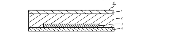
- FIG. 1 is a schematic cross-sectional view of one embodiment in which an organic light emitting element is sealed with a cured product of a curable hygroscopic resin composition for sealing an electronic device of the present invention.
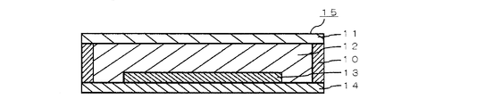
- FIG. 2 is a schematic cross-sectional view of an embodiment in which an organic light emitting element is sealed with a cured product of a curable hygroscopic resin composition for sealing an electronic device of the present invention together with a spacer for uniform sealing.
- FIG. 3 is a schematic cross-sectional view of another embodiment in which an organic light emitting element is sealed with a cured product of the curable hygroscopic resin composition for sealing an electronic device of the present invention.
- FIG. 1 is a schematic cross-sectional view of one embodiment in which an organic light emitting element is sealed with a cured product of a curable hygroscopic resin composition for sealing an electronic device of the present invention.
- FIG. 2 is a schematic cross-sectional view of an embodiment in which an organic light emitting
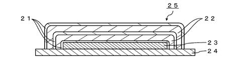
- FIG. 4 is a schematic cross-sectional view of still another embodiment in which an organic light emitting element is sealed with a cured product of the curable hygroscopic resin composition for sealing an electronic device of the present invention.
- FIG. 5 is a diagram showing (a) a test piece used in a calcium corrosion test through a glass substrate and (b) a test piece used in a calcium corrosion test in Examples and Comparative Examples. It is the figure which looked at the corroded state through the glass substrate.
- a curable hygroscopic resin composition for encapsulating an electronic device of the present invention (hereinafter also simply referred to as a resin composition for encapsulating) and preferred modes of use thereof will be described in detail with reference to the drawings. .
- the embodiment of the present invention is not limited to this.
- the sealing resin composition of the present invention is used for sealing an organic light emitting element 3 in an organic light emitting device 5, for example, as shown in FIG. More specifically, it is installed as a cured resin 2 between the organic light emitting element 3 provided on the element substrate 4 and the sealing substrate 1. Thereby, the organic light emitting element 3 is hermetically sealed between the element substrate 4 and the sealing substrate 1, and the organic light emitting device 5 having a solid adhesive sealing structure is obtained.
- an organic light-emitting device is taken as an example, but the sealing resin composition of the present invention can be used in various electronic devices. Examples of the electronic device include an organic EL display, organic EL lighting, an organic semiconductor, and an organic solar battery.
- the cured resin 2 means a cured product obtained by curing the sealing resin composition of the present invention.
- the sealing resin composition of the present invention includes a radical polymerizable compound (a), a hygroscopic compound (b) including a structure represented by the formula (1), and a photo radical polymerization initiator (c). It is a resin composition for sealing.
- a combination of the radically polymerizable compound (a), the hygroscopic compound (b) containing the structure represented by the formula (1), and the photoradical polymerization initiator (c) is used for sealing with excellent storage stability.
- a sealing resin composition can be obtained, and excellent sealing properties can be achieved when a cured resin is obtained.
- the radical polymerizable compound (a) is not particularly limited as long as it initiates a polymerization reaction by radicals generated from a polymerization initiator by light.
- Examples of the radical polymerizable compound (a) include monosubstituted ethylene compounds (styrene compounds, acrylate compounds, acrylonitrile compounds, acrylamide compounds, vinyl ester compounds, vinylamide compounds, etc.), 1,1-disubstituted ethylene compounds (methacrylates).
- the molecular weight of the radically polymerizable compound (a) is preferably less than 1,000.
- the minimum of the molecular weight of a radically polymerizable compound (a) is not specifically limited, It is preferable that it is 300 or more.
- the radically polymerizable compound (a) preferably contains one or more alicyclic skeletons and one or more polymerizable functional groups (hereinafter also referred to as “compound having an alicyclic skeleton”). .
- compound having an alicyclic skeleton By including the alicyclic skeleton, deterioration of the electronic device due to water molecules can be more efficiently suppressed when the electronic device is sealed. The reason for this is not clear, but is considered as follows.
- the radical polymerizable compound is polymerized, the bulky and rigid structure of the alicyclic skeleton is disposed in the resin cured product in close proximity, and the passage of water molecules in the resin cured product can be delayed.
- WVTR Water Vapor Transmission Rate
- Deterioration due to water molecules of an electronic device sealed with such a resin can be suppressed.
- two or more alicyclic skeletons are contained in the radical polymerizable compound molecule.
- two or more polymerizable functional groups are contained in the radical polymerizable compound molecule from the viewpoint of increasing the crosslinking density and reducing the moisture permeability.
- Examples of the polymerizable functional group include a vinyl group, a vinyl ether group, a (meth) acryloyl group, a vinylidene group, and a vinylene group.
- the alicyclic skeleton is preferably a cyclohexane skeleton, isobornyl skeleton, decalin skeleton, norbornane skeleton, dicyclopentane skeleton, tricyclodecane skeleton, hydrogenated bisphenol A, hydrogenated bisphenol F skeleton, more preferably a tricyclodecane skeleton, It is a hydrogenated bisphenol A skeleton.
- the radically polymerizable compound (a) a compound in which any of the above alicyclic skeletons is bonded to an oxygen atom (—O—) of the (meth) acrylate group through one carbon atom is more preferable.
- radical polymerizable compound examples include cyclohexane dialcohol di (meth) acrylate, dicyclopentanyl (meth) acrylate, tricyclodecane dialcohol di (meth) acrylate, cyclohexyl (meth) acrylate, adamantyl (meth) acrylate, Examples include isobornyl (meth) acrylate and tert-butylcyclohexanol (meth) acrylate.
- the content of a radically polymerizable compound (a) in order to improve water vapor
- the content of the radical polymerizable compound (a) is more preferably 70% by mass or more in 100% by mass of the encapsulating resin composition. It is particularly preferable that the content of the radical polymerizable compound (a) exceeds 80% by mass because not only the sealing property is excellent but also the impact protection property to the sealed light emitting device is excellent.
- the content of the radical polymerizable compound (a) is preferably 99.8% by mass or less in 100% by mass of the sealing resin composition. When the content of the radical polymerizable compound (a) is 90% by mass or less in 100% by mass of the encapsulating resin composition, the flexibility of the film obtained by curing the encapsulating resin composition is good. More preferred.
- a commonly used reactive diluent such as a low molecular (meth) acrylate may be used in combination with the compound having the alicyclic skeleton. I do not care.
- the reactive diluent added for this purpose may have only one polymerizable functional group.
- the end of a polyolefin such as polybutadiene having a molecular weight of 1,000 to 100,000 is (meth) acrylate via an ester bond or a urethane bond.
- a modified (meth) acrylate monomer may be appropriately blended.
- Such products include CN307, CN308, CN309, CN310, CN9014 (all trade names, manufactured by Arkema), TEAI-1000, TE-2000, EMA3000 (all trade names, manufactured by Nippon Soda Co., Ltd.), BAC- 45, SPBDA-S30 (both trade names, manufactured by Osaka Organic Chemical Industry Co., Ltd.).
- the above-mentioned viscosity adjusting compound and flexibility-imparting agent can be appropriately used in an amount within a range where the effect of the curable resin composition of the present invention can be obtained.
- the hygroscopic compound (b) is a compound including a structure represented by the following formula (1).
- the cured resin containing the hygroscopic compound (b) has good hygroscopicity. This is presumably due to the property that the M-OR contained in the hygroscopic compound (b) reacts with moisture to produce M-OH.
- the hygroscopic compound (b) will be described in detail.
- R is (i) an acyl group, (ii) a hydrocarbon group, or (iii) -O-, -S-, -CO-, between carbon-carbon bonds of the hydrocarbon group, And a group having at least one selected from the group consisting of —NH—.
- a part of hydrogen atoms that (i), (ii), and (iii) have may be substituted with a hydroxy group, a halogen atom, or a cyano group.
- M represents a boron atom or an aluminum atom.
- n is an integer of 2 to 20.
- a plurality of R and M may be the same or different.
- * 1 and * 2 each represent a binding site with a terminal group, or are bonded to each other.
- the carbon number of R is preferably 20 or less, more preferably 10 or less, further preferably 8 or less, and particularly preferably 7 or less.
- the number of carbon atoms in R Is preferably 2 or more, more preferably 5 or more.
- Examples of the (i) acyl group include a propenoyl group, a propanoyl group, a hexiloyl group, an octyroyl group, and a stearoyl group.
- the (ii) hydrocarbon group is a monovalent hydrocarbon group and may be linear, branched or cyclic. Examples of the hydrocarbon group include, for example, an alkyl group, a cycloalkyl group, an alkenyl group, and a cycloalkenyl group, and specific examples include an i-propyl group, a sec-butyl group, and an octyl group.
- a structure having an -alkylene group-L-alkyl group, -alkylene group-L-alkylene group-L-alkyl group when -O-, -S-, -CO-, and -NH- are L Etc.
- Part of the hydrogen atoms that (i), (ii), and (iii) have may be substituted with a hydroxy group, a halogen atom, or a cyano group.
- halogen atom examples include a fluorine atom, a chlorine atom, a bromine atom, and an iodine atom.
- R is preferably (i) an acyl group.
- M is a boron atom or an aluminum atom. M is preferably an aluminum atom. n is an integer of 1 to 20, preferably 2 to 20, more preferably 2 to 15, and still more preferably 3 to 10.
- * 1 and * 2 in the structure represented by the above formula (1) may be bonded to end groups such as organic groups, respectively, and the above * 1 and * 2 are bonded to each other to form a ring structure. However, * 1 and * 2 are preferably bonded to each other to form a ring structure. Examples of the terminal group include a hydroxyl group and an acyl group.
- the hygroscopic compound (b) may be a linear compound or a cyclic compound.
- the hygroscopic compound (b) preferably includes a 6-ring cyclic aluminoxane compound having the structure represented by the following formula (2) (n in the above formula (1) is 3) (hereinafter, this cyclic aluminoxane compound). Is also referred to as a “specific cyclic aluminoxane compound”).
- the hygroscopic compound contains the specific cyclic aluminoxane compound, it is considered that the cured resin obtained from the sealing resin composition of the present invention exhibits excellent adhesion and the like. This is presumably because the hygroscopic compound has appropriate compatibility with the radical polymerizable compound (a) and imparts tackiness to the sealing resin composition.
- R 1 has the same meaning as R in formula (1).
- the compound examples include aluminum oxide isopropoxide trimer (Algomer), aluminum oxide hexylate trimer (Algomer 600AF), aluminum oxide octylate trimer (Algomer 800AF), aluminum oxide stearate trimer (Algomer 1000SF) ( The names in parentheses are trade names, manufactured by Kawaken Fine Chemical Co., Ltd.).
- the content of the hygroscopic compound (b) is preferably 0.1% by mass or more in 100% by mass of the encapsulating resin composition in order to remove moisture in the encapsulating resin composition.
- the hygroscopic compound (b) is 1% by mass or more, not only moisture removal in the sealing resin composition but also moisture entering after sealing can be captured. If the hygroscopic compound (b) is 50% by mass or less in 100% by mass of the encapsulating resin composition, the water vapor barrier property of the resin cured product is not excessively reduced, and moisture penetration into the resin cured product is suppressed. And the moisture capture of the hygroscopic compound (b) can be balanced.
- the content of the hygroscopic compound (b) is 30% by mass. The following is more preferable.
- Photoradical polymerization initiator a radical photopolymerization initiator that generates radicals by light is used.
- Photoradical polymerization initiators generate radicals by exchanging hydrogen and electrons between two molecules and those that generate radicals by intramolecular cleavage (intramolecular cleavage type), depending on the reaction after absorbing light.
- intramolecular cleavage type There are two types of types (hydrogen abstraction type and electron donation type).
- Examples of the intramolecular cleavage type include benzoin compounds, benzyl ketal compounds, ⁇ -hydroxyacetophenone compounds, ⁇ -aminoacetophenone compounds, acylphosphine oxide compounds, titanocene compounds, O-acyloxime compounds, and the like.
- Examples of the hydrogen abstraction type include benzophenone compounds, Michler ketone compounds, and thioxanthone compounds.
- photoradical polymerization initiators include KAYACURE (DETX-S, BP-100, BDKM, CTX, BMS, 2-EAQ, ABQ, CPTX, EPD, ITX, QTX, BTC, MCA, etc.) (all trade names) , Nippon Kayaku Co., Ltd.), Irgacure (651, 184, 500, 819, 819 DW, 907, 369, 1173, 2959, 4265, 4263, OXE01, etc.), LUCIRIN TPO (all trade names, manufactured by BASF), Esacure (KIP100F, KB1, EB3, BP, X33, KT046, KT37, KIP150, TZT, etc.) (all are trade names, manufactured by Lamberti).
- KAYACURE DETX-S, BP-100, BDKM, CTX, BMS, 2-EAQ, ABQ, CPTX, EPD, ITX, QTX, BTC, M
- the radical photopolymerization initiator (c) is preferably blended in an amount of 0.1 to 10% by mass in 100% by mass of the sealing resin composition. Further, the blending ratio (b / c) (mass ratio) of the hygroscopic compound (b) and the photo radical polymerization initiator (c) is preferably 0.5 to 5.
- the radical photopolymerization initiator (c) is preferably used in the range of 0.1 to 15 parts by mass, more preferably in the range of 1 to 10 parts by mass with respect to 100 parts by mass of the radical polymerizable compound (a). It is.
- the amount of UV irradiation when the sealing resin composition of the present invention is cured is usually 5 to 100 mW / cm 2 in irradiation intensity (light output) and 500 to 5,000 mJ / cm 2 in irradiation amount.
- the sealing resin composition is usually cured within the irradiation time.
- the polymerization efficiency can be increased by utilizing the longer wavelength side of the irradiation energy.
- the sensitizer for example, an aromatic ketone compound typified by an anthracene compound or a benzophenone compound, or a thioxanthone compound can be suitably used.
- anthracene compounds include Anthracure (registered trademark) series, UVS-1331 (9,10-dibutoxyanthracene), UVS-1221 (both trade names, manufactured by Kawasaki Kasei Kogyo Co., Ltd.), and the like.
- benzophenone compound examples include KEMISORB 10, 11, 11S, 12, 111 (all trade names, manufactured by Chemipro Kasei Kogyo) and the like.
- thioxanthone compounds examples include DETX, ITX (both trade names, manufactured by LAMBSON), and the like.
- the photo-radical polymerization initiator in the case of non-irradiation with ultraviolet light, the photo-radical polymerization initiator does not decompose at room temperature, and thus can be stored for a long time at room temperature.
- the photo-radical polymerization initiator when it contains a radical photopolymerization initiator with a low decomposition temperature, there is almost no difference between the temperature at the time of curing (polymerization) of the encapsulating resin composition by ultraviolet irradiation and the temperature at the time of using the cured product. There is little distortion, and distortion hardly causes peeling. Furthermore, there is an advantage that peripheral members are not deteriorated by heating.
- organic light-emitting elements are generally deteriorated by heating for a long time at 90 ° C. or higher, and the reduction in light emission luminance and life becomes remarkable.
- the encapsulating resin composition using the photo radical polymerization initiator as described above can be encapsulated without heating at a high temperature, and is excellent as an encapsulating system for an organic light emitting device. Further, since polymerization is not started by heating, the coater die and the spray die can be heated at the time of application, and the application method is not limited.
- the encapsulating resin composition of the present invention preferably contains a solvent (d).
- the solvent (d) is not particularly limited as long as it is a compound that can be mixed well with other constituent materials. For example, hydrocarbons (hexane, octane, naphthene, polyisobutylene, polybutene, etc.), alcohols (butanol, etc.), ethers, esters, silicone oils are suitable.
- the solvent (d) can be used to improve the compatibility between the radical polymerizable compound (a) and the hygroscopic compound (b).
- the additive when an additive other than the hygroscopic compound (b) is added to the sealing resin composition, the additive may be used after being dissolved in the solvent (d) in advance.
- the solvent (d) include AF solvent Nos. 4 to 7 (manufactured by JX Nippon Oil & Energy Corporation) as naphthenic solvents and IP solvent series (manufactured by Idemitsu Petrochemical Co., Ltd.) as isoparaffinic solvents. it can.
- the content of the solvent (d) is preferably 0.1% by mass or more in 100% by mass of the encapsulating resin composition from the viewpoint of improving compatibility.
- An upper limit is not specifically limited, It is preferable that it is 10 mass% or less.
- the ratio d / b of the content of the solvent (d) and the hygroscopic compound (b) is preferably 2 or less from the viewpoint of water vapor barrier properties. Moreover, 0.25 or more is preferable in terms of compatibility.
- the boiling point of the solvent (d) is preferably 80 ° C. or higher from the viewpoint of compatibility and low viscosity, and more preferably 100 ° C. or higher. A boiling point of 160 ° C.
- a boiling point of 240 ° C. or higher is preferable because deterioration of the light-emitting element due to outgassing can be suppressed.
- an upper limit is not specifically limited, It is preferable that it is 400 degrees C or less.
- the sealing resin composition of the present invention may contain other additives as long as the sealing properties of the cured resin are not impaired.
- the additive include a diluent, a tackifier, a crosslinking aid, a flame retardant, a polymerization inhibitor, a filler, and a coupling agent.
- cured material is described below.
- the sealing resin composition of the present invention can suppress decomposition until the polymerization reaction starts by shielding light.
- the calcium corrosion test can be performed by the test method described in the examples. This calcium corrosion test utilizes the fact that silvery white metallic calcium with a metallic luster sealed on a glass substrate reacts with water molecules that have penetrated into the resin to become transparent calcium hydroxide. Thus, the sealing ability of the cured resin is measured. Therefore, this test is a test method closer to the actual sealing appearance.
- the radius of curvature R of the corner portion of the metal calcium layer 54 after the test shown in FIG. 5B is preferably less than 5 mm, and more preferably less than 1 mm. If the radius of curvature R is less than 5 mm in the above test, it means that the penetration of moisture into the electronic device when the electronic device is actually sealed using this resin is sufficiently small. Can be suitably used.
- the evaluation of the water vapor barrier property test described later and the above calcium corrosion test may not coincide.
- the low moisture permeability in the water vapor barrier test is one reason why the calcium corrosion test is good.
- the intrusion route of water molecules may include the case of passing through the interface between the cured resin and the substrate (sealing interface) in addition to passing through the cured resin from the contact surface between the atmosphere and the cured resin. For this reason, when the adhesiveness between the resin cured product and the substrate is not sufficient, the influence of moisture via the sealing interface becomes large, and it is considered that the evaluation of the water vapor barrier property test and the calcium corrosion test do not coincide. That is, the calcium corrosion test can confirm the sealing property from the viewpoint including the adhesion.
- the storage stability of the sealing resin composition can be evaluated by the test methods described in the examples.
- the polymerization reaction may gradually proceed depending on the storage state, gelate, and fluidity may decrease.
- the coatability may be lowered.
- the time until fluidity is no longer observed according to the above test method is preferably 4 days or longer.
- the sealing resin composition of the present invention and the cured product thereof further have the following characteristics.
- the compatibility test in a state before curing can be performed by the test methods described in the examples.
- the preferable compatibility of the resin composition for sealing it can be judged by the judgment standard as described in an Example.
- blending the compounding resin composition for sealing can be performed by the test method as described in an Example.
- the preferable compatibility of the resin cured product can be determined by the determination criteria described in the examples. In the state where it is cloudy and phase separation cannot be recognized, it is not preferable because it is not uniformly cured.
- the resin viscosity can be measured by the test method described in the examples.
- the complex viscosity n * of the encapsulating resin composition is preferably 5 Pa ⁇ s or less, and more preferably 2 Pa ⁇ s or less. If the complex viscosity n * is 5 Pa ⁇ s or less, the application work to the sealing substrate is easy.
- the encapsulating resin composition of the present invention can reduce the amount of organic gas generated from the cured resin (hereinafter also referred to as “outgas”, which may contain moisture).
- the outgas amount can be measured by the test method described in the examples.
- the outgas generation amount is preferably 500 ppm or less, and more preferably 300 ppm or less. When the outgas generation amount is 500 ppm or less, deterioration of the sealed electronic device element due to outgas can be further suppressed.
- the solvent in the sealing resin composition or the cured resin In order to reduce the outgas generation amount to 500 ppm or less, in a dryer such as a conical dryer or an evaporator, or when processed into a film, in a drying furnace, the solvent in the sealing resin composition or the cured resin, volatile organic molecules Should be removed.
- the water vapor barrier property test can be performed by the test method described in the examples.
- the moisture permeability of a 100 ⁇ m-thick resin cured product obtained by curing and forming the sealing resin composition measured by the water vapor barrier property test is 100 g / m 2 under the conditions of 40 ° C. and relative humidity of 90%.
- ⁇ 24 h or less is preferable, and 50 g / m 2 ⁇ 24 h or less is more preferable.
- the lower limit is 1 g / m 2 ⁇ 24 h or more.
- the above resin composition for sealing can be used by directly applying to an electronic device.
- said sealing resin composition can be shape
- the cured resin product of the present invention is obtained by curing the above-described sealing resin composition of the present invention.
- the sealing resin composition can be applied to an adherend such as a substrate by coating and cured into a film or block shape.
- an electronic device can be assembled using what hardened
- the cured resin of the present invention is used in electronic devices and the like. The shape of the resin cured product, molding conditions, and specific effects will be described in the following electronic device.
- the electronic device of the present invention is an electronic device, preferably an organic electronic device, cured by curing the above-described sealing resin composition of the present invention or using a cured resin.
- an organic light emitting device image display device
- the organic light emitting device 5 shown in FIG. 1 has a structure corresponding to either a so-called top emission method or bottom emission method, and the organic light emitting device 3 provided on the element substrate 4 is sealed with a cured resin 2 interposed therebetween. It is sealed with a stop substrate 1.
- the cured resin 2 means a cured product obtained by curing the sealing resin composition of the present invention.
- the sealing side surface may be exposed as shown in FIG. That is, it is not necessary to perform further sealing treatment with a glass frit or an adhesive as the side surface sealing agent. In this way, further sealing treatment with glass frit or the like can be omitted, the structure of the organic light emitting device 5 can be simplified, and weight reduction and cost reduction can be achieved.
- an organic light emitting device 5A as shown in FIG. 2 is also preferable.
- FIG. 2 shows a cross section when the organic light emitting device 5A is cut in parallel to the edge of the organic light emitting element 3 in a region where the organic light emitting element 3 (shown by a dotted line) does not exist.
- the height of the spacer b to be used is preferably substantially the same for all the spacers b from the viewpoint of improving the parallelism between the sealing substrate 1 and the element substrate 4.
- the spacer b is preferably a spherical filler or a columnar pillar formed by photolithography.
- the material of the spacer b may be either an organic material or an inorganic material as long as there is no risk of the spacer b being crushed and destroyed by the pressure when sealing the organic light emitting element.
- An organic resin is preferable because it is excellent in affinity with the sealing resin composition and resin cured product of the present invention, and a cross-linked acrylic resin is more preferable because there is little deterioration in sealing properties.
- Examples of the spacer b include ENEOS uni-powder (trade name) manufactured by JX Nippon Oil & Energy Corporation, and Haya beads (trade name) manufactured by Hayakawa Rubber Co., Ltd.
- the arrangement density of the spacers b is preferably 10 pieces / mm 2 or more, more preferably 50 pieces / mm 2 from the viewpoint of improving the parallelism between the sealing substrate 1 and the element substrate 4 and keeping the distance between the upper and lower substrates uniform. mm 2 or more, more preferably 100 pieces / mm 2 or more. When the viscosity of the sealing resin composition becomes too high, the coating operation becomes difficult. From the viewpoint of the viscosity of the sealing resin composition, the arrangement density of the spacers b is preferably 1000 pieces / mm 2 or less, more preferably 500 pieces / mm 2 or less, and further preferably 300 pieces / mm 2 or less.
- the thickness of the cured resin is preferably 0.5 ⁇ m or more, more preferably 1 ⁇ m or more, and even more preferably 2 ⁇ m or more, from the viewpoint of unevenness followability to the substrate (sealing surface). If the thickness of the cured resin is 0.5 ⁇ m or more, the unevenness of the organic light-emitting element can be sufficiently absorbed and the space between the substrates can be completely sealed. Further, from the viewpoint of sealing properties, the thickness of the cured resin is preferably 100 ⁇ m or less, more preferably 50 ⁇ m or less, and even more preferably 30 ⁇ m or less.
- the thickness of the cured resin is 100 ⁇ m or less, the surface area of the cured resin exposed to the atmosphere does not become too large, and a balance between the amount of moisture permeation and moisture capture can be achieved.
- the thickness of the cured resin product is approximately the same as the height of the spacer b when the spacer b is used.
- the sealing resin composition of the present invention has a side surface sealing structure 10 with a side surface sealing agent (glass frit or adhesive) so as to surround the periphery of the cured resin 12.
- a dam structure portion can be formed of an adhesive, a gas barrier sealing agent, a glass frit cured product, or the like.
- high airtightness is maintained by the synergistic effect of the cured resin and the side surface sealing structure 10 of the present invention.
- the organic light-emitting device 15 using the cured resin 12 obtained by the sealing resin composition of the present invention and the side surface sealing structure 10 in combination is preferable.
- the cured resin obtained from the encapsulating resin composition of the present invention may be used in an organic light emitting device 25 as shown in FIG.
- an organic light emitting element 23 formed on a gas barrier element substrate 24 is hermetically sealed by a plurality of laminated layers of an inorganic thin film 21 and an organic thin film 22.
- the cured resin becomes the organic thin film 22.
- High airtightness is maintained by the synergistic effect of the organic thin film 22 and the inorganic thin film 21 obtained by the sealing resin composition of the present invention.
- stacking is not limited to the aspect of FIG. 4, It can design arbitrarily.
- the inorganic thin film 21 is composed of a silicon nitride compound, a silicon oxide compound, an aluminum oxide compound, aluminum, or the like.
- the thickness of the single inorganic thin film 21 is preferably 1 ⁇ m or less from the viewpoint of flexibility.
- the thickness of the single organic thin film 22 is preferably 5 ⁇ m or less from the viewpoint of flexibility, but is preferably 1 ⁇ m or more from the viewpoint of impact resistance to the organic EL element, and more preferably 5 ⁇ m or more.
- the manufacturing method of the organic light-emitting device using the resin composition for sealing of the present invention is as follows.
- the sealing resin composition is applied by, for example, spin coating, dipping, spray coating, slit coating, bar coating, roll coating, gravure printing, flexographic printing, screen printing. And a flow coat method.
- the organic light emitting device 5 whose side surfaces are not hermetically sealed as shown in FIG. 1, first, the organic light emitting element 3 is covered on the organic light emitting element substrate 4 on which the organic light emitting element 3 is laminated and formed. An appropriate amount of the resin composition is applied, and the sealing substrate 1 is placed thereon so as to sandwich the sealing resin composition of the present invention.
- sealing is performed so that no space is generated between the element substrate 4 and the sealing substrate 1, and then the sealing resin composition of the present invention is cured by ultraviolet irradiation to form a cured resin 2. Stopped.
- the sealing resin composition of the present invention is first applied to the sealing substrate 1, and the sealing resin composition is sandwiched between the sealing substrate 1 and the element substrate 4 formed by stacking the organic light emitting elements 3. After that, the sealing resin composition of the present invention may be cured by ultraviolet irradiation to form a cured resin product 2 for sealing.
- the structure that reduces moisture intrusion from the side surface of the cured resin 12 can be manufactured as follows. First, the side surface sealing structure 10 is formed on the element substrate 14 or the sealing substrate 11 so as to surround the periphery of the organic light emitting element 13. Thereafter, the sealing resin composition of the present invention is poured into the side surface sealing structure 10, and the sealing resin composition of the present invention is sandwiched between the other substrate. At this time, no space is created between the element substrate 14, the sealing substrate 11, and the side surface sealing structure 10. Then, it seals by hardening the resin composition for sealing of this invention by ultraviolet irradiation, and forming the resin cured material 12. FIG. It is preferable that these sealing steps be performed in a dry environment because the deterioration of the hygroscopic properties of the sealing resin composition organism of the present invention is reduced.
- the organic light emitting device 25 as shown in FIG. 4 can be manufactured as follows. First, the organic light emitting element 23 is formed on the gas barrier element substrate 24, and the upper and side surfaces of the organic light emitting element 23 are covered with the inorganic thin film 21. Furthermore, the sealing resin composition of the present invention is applied on the inorganic thin film 21 and cured to form the organic thin film 22. An inorganic thin film 21 is further formed thereon. If necessary, the formation of the organic thin film 22 and the inorganic thin film 21 is repeated.
- the inorganic thin film 21 can be formed by plasma CVD (PECVD), PVD (physical vapor deposition), ALD (atomic layer deposition), or the like.
- the organic thin film 22 can be formed by applying the sealing resin composition of the present invention by an existing method such as an inkjet method, a spray coating method, a slit coating method, or a bar coating method, and then curing it by ultraviolet irradiation.
- an existing method such as an inkjet method, a spray coating method, a slit coating method, or a bar coating method, and then curing it by ultraviolet irradiation.
- the organic light emitting device using the sealing resin composition of the present invention may be provided with a color filter for adjusting chromaticity.
- the installation location of the color filter in this case is between the cured resin 2 (12) of the present invention and the sealing substrate 1 (11) or the element substrate 4 (14).
- the element substrate 4 (14) may be sandwiched between the color filter and the organic light emitting element 3 (13), or the sealing substrate 1 (11) and the cured resin 2 ( 12) and the organic light emitting element 3 (13) may be interposed.
- it may be placed on the outermost inorganic thin film 21 or below the element substrate 24.
- the color filter is preferably fixed with the sealing resin composition of the present invention or another transparent resin composition.
- Examples 2 to 10 and Comparative Examples 1 to 3 In place of the constituent materials used in Example 1, the constituent materials shown in Table 1 were used in the same manner as in Example 1 except that the constituent materials shown in Table 1 were used so that the total amount was 10 g.
- the sealing resin compositions of ⁇ 10 and Comparative Examples 1 to 3 were prepared. The units (mass%) of the constituent materials (a) to (d) in Table 1 are omitted.
- -Radical polymerizable compound (a)- FA-513AS (trade name, manufactured by Hitachi Chemical Co., Ltd., dicyclopentanyl acrylate)
- CD406 trade name, manufactured by Arkema, cyclohexanedimethanol diacrylate
- SR833 (trade name, manufactured by Arkema, tricyclodecane dimethanol diacrylate)
- DCP (trade name, manufactured by Shin-Nakamura Chemical Co., Ltd., tricyclodecane dimethanol diacrylate)
- Divinylbenzene manufactured by Tokyo Chemical Industry Co., Ltd.
- -Hygroscopic compound (b)- ⁇ ALCH Alluminum ethyl acetoacetate ⁇ Diisopropylate
- Algomer 600AF aluminum oxide hexylate trimer
- Algomer 800AF (aluminum oxide oct
- -Polymerization initiator (c)- V-601 (trade name, manufactured by Wako Pure Chemical Industries, diethyl-2,2′-azobis (2-methylpropionate), thermal radical polymerization initiator) ⁇ Esacure TZT (manufactured by Lamberti, mixed product of trimethylbenzophenone and methylbenzophenone, photo radical polymerization initiator) -Solvent (d)- ⁇ Hexane (Wako Pure Chemical Industries, Boiling point: 68 °C) ⁇ Butanol (manufactured by Wako Pure Chemical, boiling point: 117 ° C) AF7 solvent (trade name, manufactured by JX Nippon Oil & Energy Corporation, solvent based on naphthene, boiling point: 260 ° C)
- ⁇ Calcium corrosion test> This will be described with reference to FIG.
- a metal calcium layer 52 having a thickness of 10 mm ⁇ 10 mm and a thickness of 100 nm was formed on the glass substrate by a vacuum vapor deposition machine.
- sealing resin compositions prepared above were dripped on the metallic calcium layer, and 0.15 mm x 18 mm x 18 mm sealing glass (transparent glass) was further piled up.
- the sealing resin composition spreads between the sealing glass and the glass substrate or the metal calcium layer to form a layer having the same size as the sealing glass surface.
- a test piece was obtained by irradiating ultraviolet rays at 50 mW / cm 2 for 60 seconds (irradiation amount: 3000 mJ / cm 2 ) with an ultraviolet irradiation device.
- a test piece was obtained in the same manner as described above except that the sealing resin composition was cured by putting it in a heating furnace at 100 ° C.
- Fig.5 (a) shows the figure which looked at the said test piece through the glass substrate (however, the part of the said sealing glass is remove
- the obtained test piece was stored at a high temperature and high humidity of 60 ° C. and a relative humidity of 90%, and the corner portion of the metallic calcium layer 54 after 48 hours was observed.
- the metallic calcium layer 52 has a silvery white color with a metallic luster, but as the corrosion progresses, the corroded portion becomes transparent calcium hydroxide. For this reason, the corner portion of the metal calcium layer 54 after the test (the boundary between the metal calcium portion and the calcium hydroxide portion) appears to be round.
- the degree of corrosion in this test was evaluated using the radius of curvature R of the corner portion of the metal calcium layer 54 after the test, as shown in FIG.
- the curvature radius R was evaluated as follows. The test piece obtained above was photographed from above to obtain an image of the metal calcium layer 54 after the test. In the corner portion of the metal calcium layer 54 after the test on the obtained image, as shown by a circle indicated by a dotted line in FIG.
- Transparent state (a state in which the sealing resin composition has a degree of transparency equivalent to the transparency of the radical polymerizable compound (a) contained therein) is “A”, a state of being clouded (a sealing resin composition) However, it was evaluated as “B” for a state having transparency lower than the transparency of the radically polymerizable compound (a) contained therein, and “C” for a state where two layers were separated.
- A for transparent state (a state in which the cured film has transparency equivalent to the transparency of the radical polymerizable compound (a) contained in the sealing resin composition before curing), transparent but refracted
- B the state where phase separation can be recognized due to the rate difference
- white turbidity white turbidity is a radical in which the cured film is contained in the resin composition for sealing before curing
- C The state having transparency lower than the transparency of the polymerizable compound (a) that can be visually judged) was evaluated as “C”.
- ⁇ Viscosity measurement> The sealing resin composition prepared above was allowed to stand for 1 hour, and then measured with a dynamic viscoelasticity measuring apparatus (apparatus name “ARES”, manufactured by Rheometric Scientific) with a cone diameter of 25 mm and a cone angle of 0.
- the complex viscosity n * at room temperature (25 ° C.) was measured at a shear rate of 1 s ⁇ 1 using a 1 rad cone plate.
- a complex viscosity n * of 2 Pa ⁇ s or less was evaluated as “A”
- a viscosity exceeding 2 Pa ⁇ s to 5 Pa ⁇ s or less was evaluated as “B”
- a value exceeding 5 Pa ⁇ s was evaluated as “C”.
- ⁇ Water vapor barrier property test> A cured film having a thickness of 100 ⁇ m produced in the same manner as the test piece for the above-described compatibility test (after curing) was used as a test object, and the moisture permeability test method (cup method) of moisture-proof packaging material of JIS Z 0208 was 40.
- the moisture permeability (g / m 2 ⁇ 24 h) was measured under the conditions of 0 ° C. and a relative humidity of 90%.
- the cured film expands due to the volume change of the air in the cup, and the surface area and thickness may change, resulting in inaccurate measurement values.
- the cured film was reinforced with cellophane having a thickness of 20 ⁇ m.
- the moisture permeability of the cellophane with a thickness of 20 ⁇ m is 3,000 g / m 2 ⁇ 24 h under the same conditions, which is sufficiently larger than the moisture permeability of the cured films of the examples and comparative examples. It did not interfere with the measurement.
- the moisture permeability is 100 g / m 2 ⁇ 24 h or less, the water vapor barrier property can be evaluated as good.
- Table 1 the unit of water vapor barrier property test (g / m 2 ⁇ 24h) is omitted.
- Examples 1 to 10 the calcium corrosion test was evaluated well, and it was found that the cured film of the sealing resin composition of the present invention had high sealing properties. Further, any of the encapsulating resin compositions had high storage stability. Moreover, even if the room was not particularly dried, the sealing property was exhibited and the handling property was excellent. Furthermore, all the resin viscosities were low enough to perform the sealing operation. In addition, Examples 2 to 9 using the solvent (d) having a boiling point of 100 ° C. or higher were excellent in outgassing properties. In addition, Examples 1, 3 to 10 have higher compatibility (before curing) and compatibility (after curing) and are considered to be uniformly cured.
- the encapsulating resin composition of the present invention can be used, for example, for encapsulating the organic light emitting element 3 of the organic light emitting device of FIG.
- Comparative Example 1 using ALCH which is a hygroscopic compound having no structure of formula (1), peels off from the sealing interface during the calcium corrosion test, and the calcium corrosion test is impossible. Met.
- Comparative Example 2 in which the hygroscopic compound (b) was not used the evaluation of the calcium corrosion test was bad.
- Comparative Example 3 using the thermal radical polymerization initiator had poor storage stability.
Landscapes
- Chemical & Material Sciences (AREA)
- Organic Chemistry (AREA)
- Health & Medical Sciences (AREA)
- Chemical Kinetics & Catalysis (AREA)
- Medicinal Chemistry (AREA)
- Polymers & Plastics (AREA)
- Physics & Mathematics (AREA)
- Engineering & Computer Science (AREA)
- Materials Engineering (AREA)
- Optics & Photonics (AREA)
- Electromagnetism (AREA)
- Electroluminescent Light Sources (AREA)
- Structures Or Materials For Encapsulating Or Coating Semiconductor Devices Or Solid State Devices (AREA)
- Polymerisation Methods In General (AREA)
- Sealing Material Composition (AREA)
Abstract
ラジカル重合性化合物(a)と、下記式(1)で表される構造を含む吸湿性化合物(b)と、光ラジカル重合開始剤(c)とを含む電子デバイス封止用硬化性吸湿性樹脂組成物、上記組成物を硬化して形成されてなる樹脂硬化物、および上記組成物を硬化して封止されてなる電子デバイス。(式(1)中、Rは、(i)アシル基、(ii)炭化水素基、または(iii)前記炭化水素基の炭素-炭素結合間に-O-、-S-、-CO-、および-NH-からなる群より選択される少なくとも1種を有する基を表す。Mは、ホウ素原子またはアルミニウム原子を表す。nは、2~20の整数である。*1および*2は、各々、末端基との結合部位を示すか、互いに結合している。)
Description
本発明は、封止性の高い樹脂硬化物を形成することができる電子デバイス封止用硬化性吸湿性樹脂組成物、樹脂硬化物およびこの樹脂硬化物で封止された電子デバイスに関する。なかでも、有機電子デバイス、有機発光素子(有機EL素子)、タッチパネル、LED、および太陽電池などの電子デバイスの構成部材の封止に関するものである。
電子デバイスの一例である、有機発光素子は、使用により発光輝度や発光効率などの発光特性が徐々に劣化していくという問題がある。その原因としては、有機発光素子内に浸入した水分等による有機物の変性や電極の酸化が挙げられる。このような水分による劣化の問題は、有機発光素子以外の電子デバイスにも共通してみられる。
このような問題を防止するため、電子デバイスを封止することで、水分等が電子デバイス中に浸入することを防ぎ、電子デバイスの劣化を抑制する技術が多数検討されている。また、吸湿性物質を利用して、電子デバイス内に侵入した水分を捕獲する技術も検討されている。
さらに近年は、有機発光デバイスの分野においては、有機発光素子基板と封止基板の間が樹脂硬化物で完全充填された固体封止構造により、有機発光デバイスの厚さをより薄くし、基板界面の反射を抑えることで視認性の改善が行われている。固体封止構造を形成できる吸湿性組成物の例としては、例えば、特許文献1に、紫外線硬化剤(透光性のあるモノマーと重合開始剤とを含む)と特定の構造の有機金属化合物からなる水分吸収物質とを含む水分吸収剤が開示されている。
さらに近年は、有機発光デバイスの分野においては、有機発光素子基板と封止基板の間が樹脂硬化物で完全充填された固体封止構造により、有機発光デバイスの厚さをより薄くし、基板界面の反射を抑えることで視認性の改善が行われている。固体封止構造を形成できる吸湿性組成物の例としては、例えば、特許文献1に、紫外線硬化剤(透光性のあるモノマーと重合開始剤とを含む)と特定の構造の有機金属化合物からなる水分吸収物質とを含む水分吸収剤が開示されている。
しかしながら、特許文献1の実施例に記載されている有機EL素子用水分吸収剤は、電子デバイス中に侵入する水分による劣化の抑制が十分とはいえず、封止性が十分ではないという問題があった。
また、固体封止構造を形成するための樹脂組成物としては、重合性化合物と重合開始剤を含有するものが検討されている。しかし、このような樹脂組成物は、保存時に重合反応が進行したり、作業中に吸湿したりすることがあり、保存安定性や取扱い性について改善の余地があった。
また、固体封止構造を形成するための樹脂組成物としては、重合性化合物と重合開始剤を含有するものが検討されている。しかし、このような樹脂組成物は、保存時に重合反応が進行したり、作業中に吸湿したりすることがあり、保存安定性や取扱い性について改善の余地があった。
すなわち、本発明は、以上のような事情に基づいてなされたものであり、封止性に優れた樹脂硬化物を形成でき、さらには保存安定性や取扱い性に優れた電子デバイス封止用硬化性吸湿性樹脂組成物を提供することを課題とする。
また、本発明は、上記の電子デバイス封止用硬化性吸湿性樹脂組成物を利用した、樹脂硬化物および電子デバイスを提供することを課題とする。
また、本発明は、上記の電子デバイス封止用硬化性吸湿性樹脂組成物を利用した、樹脂硬化物および電子デバイスを提供することを課題とする。
本発明者は、樹脂硬化物を用いた封止方法について鋭意検討した。本発明者は、ラジカル重合性化合物と特定構造の吸湿性化合物とラジカル重合開始剤とを使用した硬化性吸湿性樹脂組成物を硬化させて得られる樹脂硬化物は、封止性に優れることを見出した。
また、この硬化性吸湿性樹脂組成物は、保存安定性にも優れていた。
また、この硬化性吸湿性樹脂組成物は、保存安定性にも優れていた。
すなわち、本発明の上記課題は、以下の手段によって達成された。
(1)ラジカル重合性化合物(a)と、下記式(1)で表される構造を含む吸湿性化合物(b)と、光ラジカル重合開始剤(c)とを含む電子デバイス封止用硬化性吸湿性樹脂組成物。
(1)ラジカル重合性化合物(a)と、下記式(1)で表される構造を含む吸湿性化合物(b)と、光ラジカル重合開始剤(c)とを含む電子デバイス封止用硬化性吸湿性樹脂組成物。

(式(1)中、Rは、(i)アシル基、(ii)炭化水素基、または(iii)前記炭化水素基の炭素-炭素結合間に-O-、-S-、-CO-、および-NH-からなる群より選択される少なくとも1種を有する基を表す。ただし、(i)、(ii)、および(iii)が有する水素原子の一部は、ヒドロキシ基、ハロゲン原子またはシアノ基で置換されていてもよい。Mは、ホウ素原子またはアルミニウム原子を表す。nは、2~20の整数である。複数のRおよびMは、それぞれ同一でも異なっていてもよい。*1および*2は、各々、末端基との結合部位を示すか、互いに結合している。)
(2)前記ラジカル重合性化合物(a)が(メタ)アクリレート化合物である、(1)に記載の電子デバイス封止用硬化性吸湿性樹脂組成物。
(3)前記ラジカル重合性化合物(a)が一つ以上の脂環式骨格を持つ、(1)または(2)のいずれか1つに記載の電子デバイス封止用硬化性吸湿性樹脂組成物。
(4)前記脂環式骨格がトリシクロデカン骨格および水添ビスフェノールA骨格の少なくとも一方である、(3)に記載の電子デバイス封止用硬化性吸湿性樹脂組成物。
(5)溶剤(d)を含有し、前記溶剤(d)の沸点が100℃以上である、(1)~(4)のいずれか1つに記載の電子デバイス封止用硬化性吸湿性樹脂組成物。
(6)前記溶剤(d)の沸点が160℃以上である、(5)に記載の電子デバイス封止用硬化性吸湿性樹脂組成物。
(7)前記溶剤(d)の沸点が240℃以上である、(5)または(6)に記載の電子デバイス封止用硬化性吸湿性樹脂組成物。
(8)前記溶剤(d)が、ナフテン系溶剤またはイソパラフィン系溶剤である、(5)~(7)のいずれか1つに記載の電子デバイス封止用硬化性吸湿性樹脂組成物。
(9)前記溶剤(d)と該吸湿性化合物(b)との含有量の比d/bが2以下である、(5)~(8)のいずれか1つに記載の電子デバイス封止用硬化性吸湿性樹脂組成物。
(10)前記吸湿性化合物(b)が、下記式(2)で表される、(1)~(9)のいずれか1つに記載の電子デバイス封止用硬化性吸湿性樹脂組成物。

(式(2)中、R1は、前記式(1)におけるRと同義である。)
(11)前記吸湿性化合物(b)を封止用樹脂組成物100質量%中に0.1質量%以上50質量%以下含有する、(1)~(10)のいずれか1つに記載の電子デバイス封止用硬化性吸湿性樹脂組成物。
(12)(1)~(11)のいずれか1つに記載の電子デバイス封止用硬化性吸湿性樹脂組成物を硬化することにより形成されてなる、樹脂硬化物。
(13)(1)~(11)のいずれか1つに記載の電子デバイス封止用硬化性吸湿性樹脂組成物を硬化させて封止されてなる、電子デバイス。
(14)(12)に記載の樹脂硬化物で封止されてなる、電子デバイス。
(2)前記ラジカル重合性化合物(a)が(メタ)アクリレート化合物である、(1)に記載の電子デバイス封止用硬化性吸湿性樹脂組成物。
(3)前記ラジカル重合性化合物(a)が一つ以上の脂環式骨格を持つ、(1)または(2)のいずれか1つに記載の電子デバイス封止用硬化性吸湿性樹脂組成物。
(4)前記脂環式骨格がトリシクロデカン骨格および水添ビスフェノールA骨格の少なくとも一方である、(3)に記載の電子デバイス封止用硬化性吸湿性樹脂組成物。
(5)溶剤(d)を含有し、前記溶剤(d)の沸点が100℃以上である、(1)~(4)のいずれか1つに記載の電子デバイス封止用硬化性吸湿性樹脂組成物。
(6)前記溶剤(d)の沸点が160℃以上である、(5)に記載の電子デバイス封止用硬化性吸湿性樹脂組成物。
(7)前記溶剤(d)の沸点が240℃以上である、(5)または(6)に記載の電子デバイス封止用硬化性吸湿性樹脂組成物。
(8)前記溶剤(d)が、ナフテン系溶剤またはイソパラフィン系溶剤である、(5)~(7)のいずれか1つに記載の電子デバイス封止用硬化性吸湿性樹脂組成物。
(9)前記溶剤(d)と該吸湿性化合物(b)との含有量の比d/bが2以下である、(5)~(8)のいずれか1つに記載の電子デバイス封止用硬化性吸湿性樹脂組成物。
(10)前記吸湿性化合物(b)が、下記式(2)で表される、(1)~(9)のいずれか1つに記載の電子デバイス封止用硬化性吸湿性樹脂組成物。
(11)前記吸湿性化合物(b)を封止用樹脂組成物100質量%中に0.1質量%以上50質量%以下含有する、(1)~(10)のいずれか1つに記載の電子デバイス封止用硬化性吸湿性樹脂組成物。
(12)(1)~(11)のいずれか1つに記載の電子デバイス封止用硬化性吸湿性樹脂組成物を硬化することにより形成されてなる、樹脂硬化物。
(13)(1)~(11)のいずれか1つに記載の電子デバイス封止用硬化性吸湿性樹脂組成物を硬化させて封止されてなる、電子デバイス。
(14)(12)に記載の樹脂硬化物で封止されてなる、電子デバイス。
本発明において、「~」とは、その前後に記載される数値を下限値および上限値として含む意味で使用される。
また、「(メタ)アクリレート」とは、メタクリレートおよびアクリレートのいずれでもよく、これらの総称として使用する。従って、メタクリレートおよびアクリレートのいずれか一方の場合やこれらの混合物をも含む。
また、「(メタ)アクリレート」とは、メタクリレートおよびアクリレートのいずれでもよく、これらの総称として使用する。従って、メタクリレートおよびアクリレートのいずれか一方の場合やこれらの混合物をも含む。
さらに、化合物の表示については、化合物そのもののほか、その塩、そのイオン、そのエステルを含む意味に用いる。さらに、置換または無置換を明記していない化合物については、目的とする効果を損なわない範囲で、任意の置換基を有する化合物を含む意味である。このことは、置換基等についても同様である。
本発明の封止用樹脂組成物は、ラジカル重合性化合物と特定構造の吸湿性化合物と光ラジカル重合開始剤とを含む。この封止用樹脂組成物の硬化物は、封止性に優れ、電子デバイスの構成部材を封止して水分による劣化を抑制することができる。
また、本発明の電子デバイス封止用硬化性吸湿性樹脂組成物は、保存中の封止性の劣化が抑制されておりより保存安定性に優れている。
また、本発明の電子デバイス封止用硬化性吸湿性樹脂組成物は、グローブボックス等において極度に乾燥した環境下で取り扱わなくとも、組成物の吸湿性能は劣化せず、取扱い性に優れている。
本発明の上記および他の特徴および利点は、適宜添付の図面を参照して、下記の記載からより明らかになるであろう。
また、本発明の電子デバイス封止用硬化性吸湿性樹脂組成物は、保存中の封止性の劣化が抑制されておりより保存安定性に優れている。
また、本発明の電子デバイス封止用硬化性吸湿性樹脂組成物は、グローブボックス等において極度に乾燥した環境下で取り扱わなくとも、組成物の吸湿性能は劣化せず、取扱い性に優れている。
本発明の上記および他の特徴および利点は、適宜添付の図面を参照して、下記の記載からより明らかになるであろう。
以下に、本発明の電子デバイス封止用硬化性吸湿性樹脂組成物(以下、単に、封止用樹脂組成物とも称す。)とその使用の好ましい態様を、図面を参照しながら詳細に説明する。本発明の態様はこれに限定されるものではない。
本発明の封止用樹脂組成物は、例えば、図1に示されるように、有機発光デバイス5における有機発光素子3を封止するために用いられる。より詳細には、素子基板4上に設けられた有機発光素子3と封止基板1との間に樹脂硬化物2として設置される。これにより、有機発光素子3が素子基板4と封止基板1とで気密封止され、固体密着封止構造を有する有機発光デバイス5が得られる。上記では有機発光デバイスを例にとったが、本発明の封止用樹脂組成物は各種電子デバイスにおいて利用できる。電子デバイスとしては、有機ELディスプレイ、有機EL照明、有機半導体、有機太陽電池等が挙げられる。樹脂硬化物2とは、本発明の封止用樹脂組成物を硬化させてなる硬化物を意味する。
<<電子デバイス封止用硬化性吸湿性樹脂組成物>>
本発明の封止用樹脂組成物は、ラジカル重合性化合物(a)と、式(1)で表される構造を含む吸湿性化合物(b)と、光ラジカル重合開始剤(c)とを含む封止用樹脂組成物である。
本発明においてラジカル重合性化合物(a)、式(1)で表される構造を含む吸湿性化合物(b)および光ラジカル重合開始剤(c)を併用することにより、保存安定性に優れた封止用樹脂組成物とでき、樹脂硬化物とした際に優れた封止性を発揮することができる。
本発明の封止用樹脂組成物は、ラジカル重合性化合物(a)と、式(1)で表される構造を含む吸湿性化合物(b)と、光ラジカル重合開始剤(c)とを含む封止用樹脂組成物である。
本発明においてラジカル重合性化合物(a)、式(1)で表される構造を含む吸湿性化合物(b)および光ラジカル重合開始剤(c)を併用することにより、保存安定性に優れた封止用樹脂組成物とでき、樹脂硬化物とした際に優れた封止性を発揮することができる。
<ラジカル重合性化合物(a)>
ラジカル重合性化合物(a)は、光により重合開始剤から生成したラジカルによって重合反応を開始するものであれば特に限定されない。
ラジカル重合性化合物(a)としては、例えば、一置換エチレン化合物(スチレン化合物、アクリレート化合物、アクリロニトリル化合物、アクリルアミド化合物、ビニルエステル化合物、およびビニルアミド化合物など)、1,1-二置換エチレン化合物(メタアクリレート化合物、メタクリルアミド化合物、塩化ビニリデン、フッ化ビニリデン、およびα-メチルスチレン化合物など)、1,2-二置換エチレン化合物(N-アルキル置換マレイミド化合物、アセナフチレン化合物、ビニレンカーボネート化合物、フマル酸エステル化合物およびアミド化合物など)、およびジエン化合物(1,3-ブタジエン、イソプレン、クロロプレンなど)が挙げられる。中でも(メタ)アクリレート化合物が好ましく、封止性の観点からアクリレート化合物が特に好ましい。
ラジカル重合性化合物(a)の分子量は1,000未満であることが好ましい。ラジカル重合性化合物(a)の分子量の下限は特に限定されず、300以上であることが好ましい。
ラジカル重合性化合物(a)は、光により重合開始剤から生成したラジカルによって重合反応を開始するものであれば特に限定されない。
ラジカル重合性化合物(a)としては、例えば、一置換エチレン化合物(スチレン化合物、アクリレート化合物、アクリロニトリル化合物、アクリルアミド化合物、ビニルエステル化合物、およびビニルアミド化合物など)、1,1-二置換エチレン化合物(メタアクリレート化合物、メタクリルアミド化合物、塩化ビニリデン、フッ化ビニリデン、およびα-メチルスチレン化合物など)、1,2-二置換エチレン化合物(N-アルキル置換マレイミド化合物、アセナフチレン化合物、ビニレンカーボネート化合物、フマル酸エステル化合物およびアミド化合物など)、およびジエン化合物(1,3-ブタジエン、イソプレン、クロロプレンなど)が挙げられる。中でも(メタ)アクリレート化合物が好ましく、封止性の観点からアクリレート化合物が特に好ましい。
ラジカル重合性化合物(a)の分子量は1,000未満であることが好ましい。ラジカル重合性化合物(a)の分子量の下限は特に限定されず、300以上であることが好ましい。
本発明における、ラジカル重合性化合物(a)は、一つ以上の脂環式骨格と一つ以上の重合性官能基を含むことが好ましい(以後、「脂環式骨格を有する化合物」ともいう)。脂環式骨格を含むことにより、電子デバイスを封止した際に、電子デバイスの水分子による劣化をより効率的に抑えることができる。この理由は明らかではないが、以下のように考えられる。ラジカル重合性化合物が重合することによって脂環式骨格の嵩高く剛直な構造が樹脂硬化物内で近接して配置され、樹脂硬化物中の水分子通過を遅らせることができる。その結果、透湿度(WVTR:Water Vapor Transmission Rate)が小さくなり、水蒸気バリア性が高まる。そのような樹脂で封止された電子デバイスの水分子による劣化を抑えることができる。
また、脂環式骨格を含むことにより、硬化前においても、樹脂組成物中における水分子の通過が遅くなると考えられる。
透湿度低減のためには、脂環式骨格はラジカル重合性化合物分子内に二つ以上含まれることがより好ましい。
また、架橋密度を高め透湿度を低減する観点から、重合性官能基はラジカル重合性化合物分子内に二つ以上含まれることがより好ましい。
また、脂環式骨格を含むことにより、硬化前においても、樹脂組成物中における水分子の通過が遅くなると考えられる。
透湿度低減のためには、脂環式骨格はラジカル重合性化合物分子内に二つ以上含まれることがより好ましい。
また、架橋密度を高め透湿度を低減する観点から、重合性官能基はラジカル重合性化合物分子内に二つ以上含まれることがより好ましい。
重合性官能基の例としては、例えば、ビニル基、ビニルエーテル基、(メタ)アクロイル基、ビニリデン基、およびビニレン基が挙げられる。
脂環式骨格としてはシクロヘキサン骨格、イソボルニル骨格、デカリン骨格、ノルボルナン骨格、ジシクロペンタン骨格、トリシクロデカン骨格、水添ビスフェノールA、水添ビスフェノールF骨格が好ましく、より好ましくは、トリシクロデカン骨格、水添ビスフェノールA骨格である。
ラジカル重合性化合物(a)としては、さらに上記の脂環式骨格のいずれかが(メタ)アクリレート基の酸素原子(-O-)と一つの炭素原子を介して結合する化合物がより好ましい。
ラジカル重合性化合物(a)としては、さらに上記の脂環式骨格のいずれかが(メタ)アクリレート基の酸素原子(-O-)と一つの炭素原子を介して結合する化合物がより好ましい。
ラジカル重合性化合物としては、シクロヘキサンジアルコールジ(メタ)アクリレート、ジシクロペンタニル(メタ)アクリレ-ト、トリシクロデカンジアルコールジ(メタ)アクリレート、シクロヘキシル(メタ)アクリレート、アダマンチル(メタ)アクリレート、イソボルニル(メタ)アクリレート、tert-ブチルシクロヘキサノール(メタ)アクリレートが挙げられる。
ラジカル重合性化合物としては、以下のものが市販されている。
・シクロヘキサン骨格を持つ化合物:SR217、SR420、CD406、CD421、CD401(いずれも商品名、アルケマ社製)
・イソボルニル骨格を持つ化合物:SR506、SR423(いずれも商品名、アルケマ社製)、ライトアクリレートIB-X、IB-XA(いずれも商品名、協栄社化学社製)
・トリシクロデカン骨格を持つ化合物:SR833(商品名、アルケマ社製)、A-DCP、DCP(いずれも商品名、新中村化学工業社製)、ライトアクリレートDCP-A(商品名、共栄社化学社製)、ジシクロペンテニルアクリレ-トFA-511AS、ジシクロペンテニルオキシエチルアクリレ-トFA-512AS、ジシクロペンタニルアクリレ-トFA-513AS、ジシクロペンテニルオキシエチルメタクリレートFA-512M、ジシクロペンテニルオキシエチルメタクリレ-トFA-512MT、ジシクロペンタニルメタクリレートFA-513M(いずれも商品名、日立化成社製)
・シクロヘキサン骨格を持つ化合物:SR217、SR420、CD406、CD421、CD401(いずれも商品名、アルケマ社製)
・イソボルニル骨格を持つ化合物:SR506、SR423(いずれも商品名、アルケマ社製)、ライトアクリレートIB-X、IB-XA(いずれも商品名、協栄社化学社製)
・トリシクロデカン骨格を持つ化合物:SR833(商品名、アルケマ社製)、A-DCP、DCP(いずれも商品名、新中村化学工業社製)、ライトアクリレートDCP-A(商品名、共栄社化学社製)、ジシクロペンテニルアクリレ-トFA-511AS、ジシクロペンテニルオキシエチルアクリレ-トFA-512AS、ジシクロペンタニルアクリレ-トFA-513AS、ジシクロペンテニルオキシエチルメタクリレートFA-512M、ジシクロペンテニルオキシエチルメタクリレ-トFA-512MT、ジシクロペンタニルメタクリレートFA-513M(いずれも商品名、日立化成社製)
ラジカル重合性化合物(a)の含有量としては、水蒸気バリア性を高めるためには封止用樹脂組成物100質量%中50質量%以上が好ましい。十分な架橋密度によって良好な水蒸気バリア性を保つには、ラジカル重合性化合物(a)の含有量は封止用樹脂組成物100質量%中の70質量%以上がより好ましい。ラジカル重合性化合物(a)の含有量が80質量%を超えると封止性に優れるだけでなく、封止した発光素子への衝撃保護性に優れるので特に好ましい。
ラジカル重合性化合物(a)の含有量は封止用樹脂組成物100質量%中の99.8質量%以下が好ましい。ラジカル重合性化合物(a)の含有量が封止用樹脂組成物100質量%中の90質量%以下であると封止用樹脂組成物を硬化することにより得られるフィルムの屈曲性が良好でありより好ましい。
ラジカル重合性化合物(a)の含有量は封止用樹脂組成物100質量%中の99.8質量%以下が好ましい。ラジカル重合性化合物(a)の含有量が封止用樹脂組成物100質量%中の90質量%以下であると封止用樹脂組成物を硬化することにより得られるフィルムの屈曲性が良好でありより好ましい。
また、封止用樹脂組成物の粘度調節のためには、一般に用いられている低分子の(メタ)アクリレートなどの反応性希釈剤を、上記の脂環式骨格を有する化合物と併用しても構わない。この目的のために添加される反応性希釈剤が有する重合性官能基は一つであっても構わない。
さらに、樹脂硬化物に柔軟性を付与するために、柔軟性付与剤として、分子量が1,000~100,000の、ポリブタジエン等のポリオレフィンの末端がエステル結合またはウレタン結合を介して(メタ)アクリレート化された(メタ)アクリレートモノマーを適宜配合してもよい。このようなものとしては、CN307、CN308、CN309、CN310、CN9014(いずれも商品名、アルケマ社製)、TEAI-1000、TE-2000、EMA3000(いずれも商品名、日本曹達社製)、BAC-45、SPBDA-S30(いずれも商品名、大阪有機化学工業社製)が挙げられる。
上記の粘度調節用の化合物や柔軟性付与剤は、本発明の硬化性樹脂組成物の効果が得られる範囲の量で適宜使用することができる。
<吸湿性化合物(b)>
吸湿性化合物(b)は、下記式(1)で表される構造を含む化合物である。
この吸湿性化合物(b)を含む樹脂硬化物は、良好な吸湿性を有する。これは、吸湿性化合物(b)が有するM-ORが水分と反応してM-OHを生成する性質によるものと推定される。以下、吸湿性化合物(b)について詳述する。
吸湿性化合物(b)は、下記式(1)で表される構造を含む化合物である。
この吸湿性化合物(b)を含む樹脂硬化物は、良好な吸湿性を有する。これは、吸湿性化合物(b)が有するM-ORが水分と反応してM-OHを生成する性質によるものと推定される。以下、吸湿性化合物(b)について詳述する。

上記式(1)中、Rは、(i)アシル基、(ii)炭化水素基、または(iii)前記炭化水素基の炭素-炭素結合間に-O-、-S-、-CO-、および-NH-からなる群より選択される少なくとも1種を有する基を表す。ただし、(i)、(ii)、および(iii)が有する水素原子の一部は、ヒドロキシ基、ハロゲン原子またはシアノ基で置換されていてもよい。Mは、ホウ素原子またはアルミニウム原子を表す。nは、2~20の整数である。複数のRおよびMは、それぞれ同一でも異なっていてもよい。*1および*2は、各々、末端基との結合部位を示すか、または互いに結合している。
上記Rで表される(i)アシル基、(ii)炭化水素基、または(iii)(ii)の炭化水素基の炭素-炭素結合間に-O-、-S-、-CO-、および-NH-からなる群より選択される少なくとも1種を有する基、の炭素数はいずれも1~30であることが好ましい。ラジカル重合性化合物(a)との相溶性の面からは、Rの炭素数は20以下が好ましく、10以下がより好ましく、8以下がさらに好ましく、7以下が特に好ましい。また、アウトガスの発生を防ぎ、また、吸湿により生じる上記R由来のアルコールやカルボン酸等の化合物が、樹脂硬化物中を移動して、電子デバイスを劣化させることを防ぐには、Rの炭素数は2以上が好ましく、5以上がより好ましい。
上記(i)アシル基の例としては、例えば、プロペノイル基、プロパノイル基、ヘキシロイル基、オクチロイル基、ステアロイル基などが挙げられる。
上記(ii)炭化水素基は、1価の炭化水素基であり、直鎖状でも分岐状でも環状でもよい。炭化水素基の例としては、例えば、アルキル基、シクロアルキル基、アルケニル基、シクロアルケニル基であり、具体的にはi-プロピル基、sec-ブチル基、オクチル基などが挙げられる。
上記(iii)(ii)の炭化水素基の炭素-炭素結合間に-O-、-S-、-CO-、および-NH-からなる群より選択される少なくとも1種を有する基としては、-O-、-S-、-CO-、および-NH-をLとした場合に、-アルキレン基-L-アルキル基、-アルキレン基-L-アルキレン基-L-アルキル基の構造を取るものなどが挙げられる。
上記(i)、(ii)、および(iii)が有する水素原子の一部は、ヒドロキシ基、ハロゲン原子またはシアノ基によって置換されていてもよい。この場合のハロゲン原子としては、例えば、フッ素原子、塩素原子、臭素原子、ヨウ素原子等が挙げられる。
アウトガスを抑制する観点からは、Rは(i)アシル基であることが好ましい。
上記(ii)炭化水素基は、1価の炭化水素基であり、直鎖状でも分岐状でも環状でもよい。炭化水素基の例としては、例えば、アルキル基、シクロアルキル基、アルケニル基、シクロアルケニル基であり、具体的にはi-プロピル基、sec-ブチル基、オクチル基などが挙げられる。
上記(iii)(ii)の炭化水素基の炭素-炭素結合間に-O-、-S-、-CO-、および-NH-からなる群より選択される少なくとも1種を有する基としては、-O-、-S-、-CO-、および-NH-をLとした場合に、-アルキレン基-L-アルキル基、-アルキレン基-L-アルキレン基-L-アルキル基の構造を取るものなどが挙げられる。
上記(i)、(ii)、および(iii)が有する水素原子の一部は、ヒドロキシ基、ハロゲン原子またはシアノ基によって置換されていてもよい。この場合のハロゲン原子としては、例えば、フッ素原子、塩素原子、臭素原子、ヨウ素原子等が挙げられる。
アウトガスを抑制する観点からは、Rは(i)アシル基であることが好ましい。
上記Mは、ホウ素原子またはアルミニウム原子である。Mとしては、アルミニウム原子が好ましい。
nは1~20の整数であり、2~20であることが好ましく、2~15であることがより好ましく、3~10であることがさらに好ましい。
上記式(1)で表される構造中の*1および*2には、それぞれ有機基等の末端基が結合していてもよく、上記*1および*2が互いに結合して環構造を形成していてもよいが、上記*1および*2が互いに結合して環構造を形成していることが好ましい。
末端基の例としては、水酸基、アシル基などが挙げられる。
nは1~20の整数であり、2~20であることが好ましく、2~15であることがより好ましく、3~10であることがさらに好ましい。
上記式(1)で表される構造中の*1および*2には、それぞれ有機基等の末端基が結合していてもよく、上記*1および*2が互いに結合して環構造を形成していてもよいが、上記*1および*2が互いに結合して環構造を形成していることが好ましい。
末端基の例としては、水酸基、アシル基などが挙げられる。
吸湿性化合物(b)は、線状の化合物であっても、環状の化合物であってもよい。
吸湿性化合物(b)としては、下記式(2)に示す構造(上記式(1)のnが3)を持つ、環員数6の環状アルミノキサン化合物を含むことが好ましい(以下、この環状アルミノキサン化合物を「特定環状アルミノキサン化合物」ともいう)。当該吸湿性化合物が上記特定環状アルミノキサン化合物を含むことで、本発明の封止用樹脂組成物から得られた樹脂硬化物は優れた密着性等を示すと考えられる。これは、当該吸湿性化合物が、ラジカル重合性化合物(a)に対して適度な相溶性を有し、また、封止用樹脂組成物に粘着性を付与するためと考えられる。
吸湿性化合物(b)としては、下記式(2)に示す構造(上記式(1)のnが3)を持つ、環員数6の環状アルミノキサン化合物を含むことが好ましい(以下、この環状アルミノキサン化合物を「特定環状アルミノキサン化合物」ともいう)。当該吸湿性化合物が上記特定環状アルミノキサン化合物を含むことで、本発明の封止用樹脂組成物から得られた樹脂硬化物は優れた密着性等を示すと考えられる。これは、当該吸湿性化合物が、ラジカル重合性化合物(a)に対して適度な相溶性を有し、また、封止用樹脂組成物に粘着性を付与するためと考えられる。
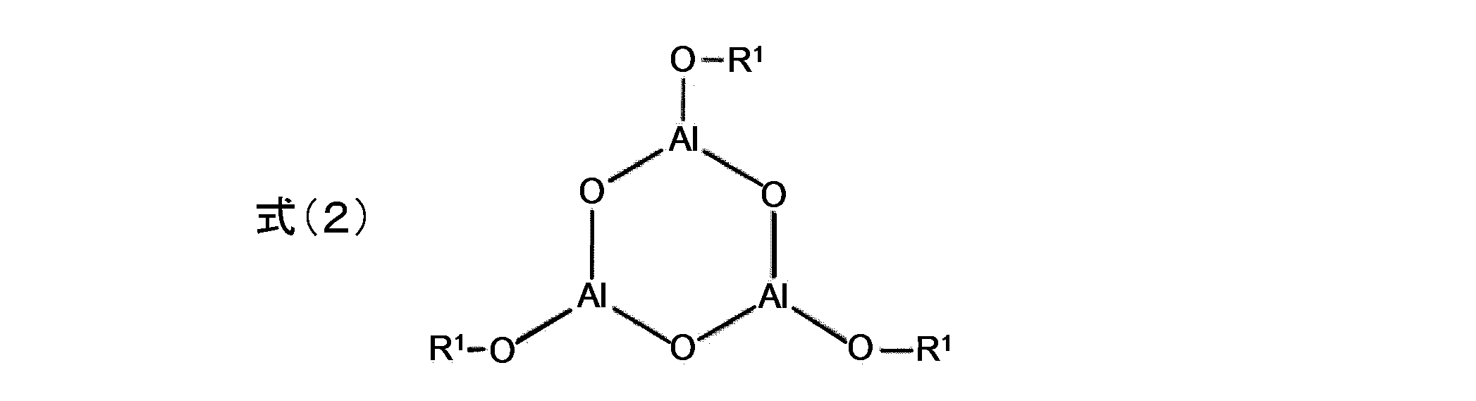
R1は式(1)のRと同義である。
具体的な化合物としては、例えば、アルミニウムオキサイドイソプロポキサイドトリマー(アルゴマー)、アルミニウムオキサイドヘキシレートトリマー(アルゴマー600AF)、アルミニウムオキサイドオクチレートトリマー(アルゴマー800AF)、アルミニウムオキサイドステアレートトリマー(アルゴマー1000SF)(括弧内はいずれも商品名、川研ファインケミカル社製)が挙げられる。
吸湿性化合物(b)の含有量としては、封止用樹脂組成物中の水分除去のためには封止用樹脂組成物100質量%中の0.1質量%以上が好ましい。吸湿性化合物(b)が1質量%以上であると、封止用樹脂組成物中の水分除去だけでなく、封止後に侵入してくる水分を捕獲することもでき、より好ましい。
吸湿性化合物(b)が封止用樹脂組成物100質量%中50質量%以下であれば、樹脂硬化物の水蒸気バリア性の低下が過度とならず、樹脂硬化物中への水分侵入の抑制と吸湿性化合物(b)の水分捕獲とのバランスが取れる。樹脂硬化物中への水分侵入の抑制と吸湿性化合物(b)の水分捕獲とのバランスを取って、良好な封止性を保つには、吸湿性化合物(b)の含有量は30質量%以下がより好ましい。
吸湿性化合物(b)が封止用樹脂組成物100質量%中50質量%以下であれば、樹脂硬化物の水蒸気バリア性の低下が過度とならず、樹脂硬化物中への水分侵入の抑制と吸湿性化合物(b)の水分捕獲とのバランスが取れる。樹脂硬化物中への水分侵入の抑制と吸湿性化合物(b)の水分捕獲とのバランスを取って、良好な封止性を保つには、吸湿性化合物(b)の含有量は30質量%以下がより好ましい。
<光ラジカル重合開始剤(c)>
重合開始剤としては光によりラジカルを生じる、光ラジカル重合開始剤を使用する。
光ラジカル重合開始剤は光を吸収した後の反応の仕方により,分子内開裂によりラジカルを発生するタイプ(分子内開裂型)と、2分子間で水素や電子をやり取りをしてラジカルを発生するタイプ(水素引き抜き型および電子供与型)の大きく2種に分類できる。
分子内開裂型としては、ベンゾイン化合物、ベンジルケタール化合物、α-ヒドロキシアセトフェノン化合物、α-アミノアセトフェノン化合物、アシルフォスフィンオキサイド化合物、チタノセン化合物、O-アシルオキシム化合物等が挙げられる。
水素引抜型としては、ベンゾフェノン化合物、ミヒラーケトン化合物、チオキサントン化合物等が挙げられる。
重合開始剤としては光によりラジカルを生じる、光ラジカル重合開始剤を使用する。
光ラジカル重合開始剤は光を吸収した後の反応の仕方により,分子内開裂によりラジカルを発生するタイプ(分子内開裂型)と、2分子間で水素や電子をやり取りをしてラジカルを発生するタイプ(水素引き抜き型および電子供与型)の大きく2種に分類できる。
分子内開裂型としては、ベンゾイン化合物、ベンジルケタール化合物、α-ヒドロキシアセトフェノン化合物、α-アミノアセトフェノン化合物、アシルフォスフィンオキサイド化合物、チタノセン化合物、O-アシルオキシム化合物等が挙げられる。
水素引抜型としては、ベンゾフェノン化合物、ミヒラーケトン化合物、チオキサントン化合物等が挙げられる。
市販の光ラジカル重合開始剤としては、KAYACURE(DETX-S、BP-100、BDMK、CTX、BMS、2-EAQ、ABQ、CPTX、EPD、ITX、QTX、BTC、MCAなど)(いずれも商品名、日本化薬社製)、Irgacure(651、184、500、819、819DW、907、369、1173、2959、4265、4263、OXE01など)、LUCIRIN TPO(いずれも商品名、BASF社製)、Esacure(KIP100F、KB1、EB3、BP、X33、KT046、KT37、KIP150、TZTなど)(いずれも商品名、Lamberti社製)などが挙げられる。
光ラジカル重合開始剤(c)は、封止用樹脂組成物100質量%中に0.1~10質量%配合されることが好ましい。
また、吸湿性化合物(b)と光ラジカル重合開始剤(c)との配合比(b/c)(質量比)が、0.5~5であると好ましい。
光ラジカル重合開始剤(c)は、ラジカル重合性化合物(a)100質量部に対して、0.1~15質量部の範囲で使用することが好ましく、より好ましくは1~10質量部の範囲である。
本発明の封止用樹脂組成物を硬化させる際の紫外線の照射量は、通常、照射強度(光出力)5~100mW/cm2、照射量500~5,000mJ/cm2であり、これによって上記封止用樹脂組成物は、通常、照射時間内に硬化する。
また、吸湿性化合物(b)と光ラジカル重合開始剤(c)との配合比(b/c)(質量比)が、0.5~5であると好ましい。
光ラジカル重合開始剤(c)は、ラジカル重合性化合物(a)100質量部に対して、0.1~15質量部の範囲で使用することが好ましく、より好ましくは1~10質量部の範囲である。
本発明の封止用樹脂組成物を硬化させる際の紫外線の照射量は、通常、照射強度(光出力)5~100mW/cm2、照射量500~5,000mJ/cm2であり、これによって上記封止用樹脂組成物は、通常、照射時間内に硬化する。
また、増感剤を併用することで、照射エネルギーの長波長側を利用して重合効率を高めることもできる。増感剤としては、例えば、アントラセン化合物やベンゾフェノン化合物に代表される芳香族ケトン化合物、チオキサントン化合物を好適に用いることができる。
アントラセン化合物の例としては、アントラキュアー(登録商標)シリーズ、UVS-1331(9,10-ジブトキシアントラセン)、UVS-1221(いずれも商品名、川崎化成工業社製)等が挙げられる。
ベンゾフェノン化合物の例としては、KEMISORB 10、11、11S、12、111(いずれも商品名、ケミプロ化成工業製)等が挙げられる。
チオキサントン化合物の例としては、DETX、ITX(いずれも商品名、LAMBSON社製)等が挙げられる。
アントラセン化合物の例としては、アントラキュアー(登録商標)シリーズ、UVS-1331(9,10-ジブトキシアントラセン)、UVS-1221(いずれも商品名、川崎化成工業社製)等が挙げられる。
ベンゾフェノン化合物の例としては、KEMISORB 10、11、11S、12、111(いずれも商品名、ケミプロ化成工業製)等が挙げられる。
チオキサントン化合物の例としては、DETX、ITX(いずれも商品名、LAMBSON社製)等が挙げられる。
重合開始剤として光ラジカル重合開始剤を選択することにより、紫外線非照射の場合には、常温では光ラジカル重合開始剤の分解は起こらないので、常温による長期保管が可能である。また、分解温度の低い光ラジカル重合開始剤を含む場合、紫外線照射による封止用樹脂組成物の硬化時(重合時)の温度と硬化物の使用時の温度に差がほとんどないので、熱収縮ひずみも少なく、ひずみが剥離の原因になることも少ない。さらに、加熱による周辺部材の劣化が無いことも利点である。特に、有機発光素子は一般的に90℃以上での長時間加熱により劣化が起こり、発光輝度や寿命の低下が顕著となる。上記のような光ラジカル重合開始剤を使用した封止用樹脂組成物は、高温加熱を伴わずに封止ができ、有機発光素子の封止システムとして優れている。
また、加熱によっては重合が開始されないので、塗布時にコーターダイやスプレーの口金を加熱することが可能であるので、塗布の方法が限定されない。
また、加熱によっては重合が開始されないので、塗布時にコーターダイやスプレーの口金を加熱することが可能であるので、塗布の方法が限定されない。
<溶剤(d)>
本発明の封止用樹脂組成物は溶剤(d)を含むことが好ましい。
溶剤(d)はその他の構成材料と良好に混合できる化合物であれば、特に限定されない。例えば、炭化水素(ヘキサン、オクタン、ナフテン、ポリイソブチレン、およびポリブテン等)、アルコール(ブタノール等)、エーテル、エステル、シリコーンオイルが好適である。溶剤(d)は、ラジカル重合性化合物(a)と吸湿性化合物(b)との相溶性を向上させるために用いることができる。また、吸湿性化合物(b)以外の添加剤を封止用樹脂組成物に添加する際に、予めその添加剤を溶剤(d)に溶解してから添加するために用いてもよい。
溶剤(d)の例としては、ナフテン系溶剤としてAFソルベント4号~7号(JX日鉱日石エネルギー社製)、イソパラフィン系溶剤としてIPソルベントシリーズ(出光石油化学株式会社製)などを挙げることができる。
本発明の封止用樹脂組成物は溶剤(d)を含むことが好ましい。
溶剤(d)はその他の構成材料と良好に混合できる化合物であれば、特に限定されない。例えば、炭化水素(ヘキサン、オクタン、ナフテン、ポリイソブチレン、およびポリブテン等)、アルコール(ブタノール等)、エーテル、エステル、シリコーンオイルが好適である。溶剤(d)は、ラジカル重合性化合物(a)と吸湿性化合物(b)との相溶性を向上させるために用いることができる。また、吸湿性化合物(b)以外の添加剤を封止用樹脂組成物に添加する際に、予めその添加剤を溶剤(d)に溶解してから添加するために用いてもよい。
溶剤(d)の例としては、ナフテン系溶剤としてAFソルベント4号~7号(JX日鉱日石エネルギー社製)、イソパラフィン系溶剤としてIPソルベントシリーズ(出光石油化学株式会社製)などを挙げることができる。
溶剤(d)の含有量は、相溶性を改善する観点からは、封止用樹脂組成物100質量%中の0.1質量%以上が好ましい。上限は特に限定されず、10質量%以下であることが好ましい。
溶剤(d)と吸湿性化合物(b)の含有量の比d/bは、水蒸気バリア性の点では2以下が好ましい。また、相溶性の点では0.25以上が好ましい。
また、溶剤(d)の沸点が80℃以上であると相溶性と低粘度化の点から好ましく、100℃以上であることがより好ましい。沸点が160℃以上であると保存安定性の点で好ましく、沸点が240℃以上であるとアウトガスによる光発光素子の劣化が抑えられるので好ましい。上限は特に限定されないが、400℃以下であることが好ましい。
溶剤(d)と吸湿性化合物(b)の含有量の比d/bは、水蒸気バリア性の点では2以下が好ましい。また、相溶性の点では0.25以上が好ましい。
また、溶剤(d)の沸点が80℃以上であると相溶性と低粘度化の点から好ましく、100℃以上であることがより好ましい。沸点が160℃以上であると保存安定性の点で好ましく、沸点が240℃以上であるとアウトガスによる光発光素子の劣化が抑えられるので好ましい。上限は特に限定されないが、400℃以下であることが好ましい。
(添加剤)
本発明の封止用樹脂組成物は、樹脂硬化物の封止性を損なわない範囲で、他の添加剤を含有していてもよい。添加剤としては、希釈剤、粘着付与剤、架橋助剤、難燃剤、重合禁止剤、フィラー、カップリング剤等が挙げられる。
本発明の封止用樹脂組成物は、樹脂硬化物の封止性を損なわない範囲で、他の添加剤を含有していてもよい。添加剤としては、希釈剤、粘着付与剤、架橋助剤、難燃剤、重合禁止剤、フィラー、カップリング剤等が挙げられる。
<電子デバイス封止用硬化性吸湿性樹脂組成物および樹脂硬化物の特性>
本発明の封止用樹脂組成物及びその硬化物である樹脂硬化物の特性について以下に述べる。
本発明の封止用樹脂組成物は、遮光することにより、重合反応開始まで、その分解を抑制することができる。
本発明の封止用樹脂組成物及びその硬化物である樹脂硬化物の特性について以下に述べる。
本発明の封止用樹脂組成物は、遮光することにより、重合反応開始まで、その分解を抑制することができる。
(封止性:カルシウム腐食試験)
カルシウム腐食試験は、実施例に記載の試験法によって行うことができる。
なお、このカルシウム腐食試験は、ガラス基板上に封止された金属光沢を有する銀白色の金属カルシウムが、樹脂中に浸入してきた水分子と反応して透明の水酸化カルシウムになることを利用して、樹脂硬化物の封止能力を測るものである。そのため、本試験は、実際の封止の姿により近い試験方法である。
上記試験による試験片において、図5(b)に示す、試験後の金属カルシウム層54のコーナー部分の曲率半径Rが、5mm未満であることが好ましく、1mm未満であることがより好ましい。
上記試験において曲率半径Rが5mm未満であれば、実際にこの樹脂を用いて電子デバイスを封止した場合の水分の電子デバイス内部への浸入が十分に少ないということであり、電子デバイスの封止に好適に用いることができる。
カルシウム腐食試験は、実施例に記載の試験法によって行うことができる。
なお、このカルシウム腐食試験は、ガラス基板上に封止された金属光沢を有する銀白色の金属カルシウムが、樹脂中に浸入してきた水分子と反応して透明の水酸化カルシウムになることを利用して、樹脂硬化物の封止能力を測るものである。そのため、本試験は、実際の封止の姿により近い試験方法である。
上記試験による試験片において、図5(b)に示す、試験後の金属カルシウム層54のコーナー部分の曲率半径Rが、5mm未満であることが好ましく、1mm未満であることがより好ましい。
上記試験において曲率半径Rが5mm未満であれば、実際にこの樹脂を用いて電子デバイスを封止した場合の水分の電子デバイス内部への浸入が十分に少ないということであり、電子デバイスの封止に好適に用いることができる。
なお、後述する水蒸気バリア性試験と上記カルシウム腐食試験の評価は一致しないこともある。水蒸気バリア試験において透湿度が低いことは、上記カルシウム腐食試験が良好である理由の1つとして挙げられる。ただし、水分子の侵入経路としては、大気と樹脂硬化物の接触面から樹脂硬化物中を経由する他に、樹脂硬化物と基板の界面(封止界面)を経由する場合も挙げられる。このため、樹脂硬化物と基板間の密着性が十分でない場合には封止界面経由の水分の影響が大きくなり、水蒸気バリア性試験とカルシウム腐食試験の評価が一致しないと考えられる。つまり、カルシウム腐食試験は、密着性も含めた観点から封止性を確認できる。
(保存安定性)
封止用樹脂組成物の保存安定性の評価は、実施例に記載の試験法によって行うことができる。
封止用樹脂組成物においては、保管状態によって重合反応が徐々に進行し、ゲル化して流動性が低くなることがある。流動性が低くなると塗布性が低下することがある。
上記試験法による、流動性が認められなくなるまでの時間は、4日以上であることが好ましい。
封止用樹脂組成物の保存安定性の評価は、実施例に記載の試験法によって行うことができる。
封止用樹脂組成物においては、保管状態によって重合反応が徐々に進行し、ゲル化して流動性が低くなることがある。流動性が低くなると塗布性が低下することがある。
上記試験法による、流動性が認められなくなるまでの時間は、4日以上であることが好ましい。
本発明の封止用樹脂組成物およびその硬化物は、下記の特性をさらに有することが好ましい。
(相溶性(配合後硬化前))
封止用樹脂組成物を配合した後、硬化を行う前の状態における相溶性試験は、実施例に記載の試験法によって行うことができる。
封止用樹脂組成物の好ましい相溶性については、実施例に記載の判断基準により判断することができる。
なお、二層分離した状態では、均一に硬化することができないため、好ましくない。
封止用樹脂組成物を配合した後、硬化を行う前の状態における相溶性試験は、実施例に記載の試験法によって行うことができる。
封止用樹脂組成物の好ましい相溶性については、実施例に記載の判断基準により判断することができる。
なお、二層分離した状態では、均一に硬化することができないため、好ましくない。
(相溶性(硬化後))
また、配合した封止用樹脂組成物を硬化した後の状態における相溶性試験は、実施例に記載の試験法によって行うことができる。
樹脂硬化物の好ましい相溶性については、実施例に記載の判断基準により判断することができる。白濁しており相分離が認識できない状態では、均一に硬化されていないため、好ましくない。
また、配合した封止用樹脂組成物を硬化した後の状態における相溶性試験は、実施例に記載の試験法によって行うことができる。
樹脂硬化物の好ましい相溶性については、実施例に記載の判断基準により判断することができる。白濁しており相分離が認識できない状態では、均一に硬化されていないため、好ましくない。
(粘度)
樹脂粘度の測定は、実施例に記載の試験法によって行うことができる。
封止用樹脂組成物の複素粘度n*は、5Pa・s以下が好ましく、2Pa・s以下がより好ましい。複素粘度n*が5Pa・s以下であれば、封止基板への塗布作業が容易である。
樹脂粘度の測定は、実施例に記載の試験法によって行うことができる。
封止用樹脂組成物の複素粘度n*は、5Pa・s以下が好ましく、2Pa・s以下がより好ましい。複素粘度n*が5Pa・s以下であれば、封止基板への塗布作業が容易である。
(アウトガス量)
本発明の封止用樹脂組成物は、その樹脂硬化物から発生する有機ガス(以後「アウトガス」ともいう。水分を含んでいてもよい。)の発生量を少なくできる。アウトガス量の測定は、実施例に記載の試験法によって行うことができる。アウトガス発生量が500ppm以下であることが好ましく、300ppm以下であることがより好ましい。アウトガス発生量が500ppm以下である場合、封止された電子デバイス用素子のアウトガスによる劣化をより抑制することができる。
アウトガス発生量を500ppm以下とするためには、コニカルドライヤー等の乾燥機やエバポレーター、フィルム状に加工した場合は乾燥炉で、封止用樹脂組成物または樹脂硬化物中の溶剤、揮発性有機分子を除去するとよい。
本発明の封止用樹脂組成物は、その樹脂硬化物から発生する有機ガス(以後「アウトガス」ともいう。水分を含んでいてもよい。)の発生量を少なくできる。アウトガス量の測定は、実施例に記載の試験法によって行うことができる。アウトガス発生量が500ppm以下であることが好ましく、300ppm以下であることがより好ましい。アウトガス発生量が500ppm以下である場合、封止された電子デバイス用素子のアウトガスによる劣化をより抑制することができる。
アウトガス発生量を500ppm以下とするためには、コニカルドライヤー等の乾燥機やエバポレーター、フィルム状に加工した場合は乾燥炉で、封止用樹脂組成物または樹脂硬化物中の溶剤、揮発性有機分子を除去するとよい。
(水蒸気バリア性)
水蒸気バリア性試験は、実施例に記載の試験法によって行うことができる。
上記水蒸気バリア性試験で測定される、封止用樹脂組成物を硬化、形成されてなる、厚さ100μmの樹脂硬化物の透湿度は、40℃、相対湿度90%の条件で100g/m2・24h以下が好ましく、50g/m2・24h以下がより好ましい。なお、下限値は、現実的には1g/m2・24h以上である。
水蒸気バリア性試験は、実施例に記載の試験法によって行うことができる。
上記水蒸気バリア性試験で測定される、封止用樹脂組成物を硬化、形成されてなる、厚さ100μmの樹脂硬化物の透湿度は、40℃、相対湿度90%の条件で100g/m2・24h以下が好ましく、50g/m2・24h以下がより好ましい。なお、下限値は、現実的には1g/m2・24h以上である。
上記の封止用樹脂組成物は、電子デバイスに直接塗布して使用することができる。また、上記の封止用樹脂組成物はフィルム等の形状に成形でき、電子デバイスに組み込んで使用することができる。
<<樹脂硬化物>>
本発明の樹脂硬化物は、上述の本発明の封止用樹脂組成物を硬化することにより得られる。封止用樹脂組成物を塗布により基板などの被着体に付与し、フィルム状、ブロック状などの形状に硬化させて使用することができる。また、封止用樹脂組成物を、フィルム状、ブロック状等の形状に予め硬化させたものを用いて、電子デバイスを組み立てることができる。
本発明の樹脂硬化物は、電子デバイス等において使用される。樹脂硬化物の形状、および成形条件、また具体的な効果については、下記の電子デバイスにおいて記載する。
本発明の樹脂硬化物は、上述の本発明の封止用樹脂組成物を硬化することにより得られる。封止用樹脂組成物を塗布により基板などの被着体に付与し、フィルム状、ブロック状などの形状に硬化させて使用することができる。また、封止用樹脂組成物を、フィルム状、ブロック状等の形状に予め硬化させたものを用いて、電子デバイスを組み立てることができる。
本発明の樹脂硬化物は、電子デバイス等において使用される。樹脂硬化物の形状、および成形条件、また具体的な効果については、下記の電子デバイスにおいて記載する。
<<電子デバイス>>
本発明の電子デバイスは、上述の本発明の封止用樹脂組成物を硬化させてまたは樹脂硬化物を用いて封止された電子デバイス、好ましくは、有機電子デバイスである。
以下に、有機電子デバイスの例として、有機発光デバイス(画像表示装置)を用いて説明する。
本発明の電子デバイスは、上述の本発明の封止用樹脂組成物を硬化させてまたは樹脂硬化物を用いて封止された電子デバイス、好ましくは、有機電子デバイスである。
以下に、有機電子デバイスの例として、有機発光デバイス(画像表示装置)を用いて説明する。
図1に示す有機発光デバイス5は、いわゆるトップエミッション方式またはボトムエミッション方式のいずれにも対応する構造であり、素子基板4上に設けられた有機発光素子3が、樹脂硬化物2を介して封止基板1により封止されている。樹脂硬化物2とは、本発明の封止用樹脂組成物を硬化させてなる硬化物を意味する。
なお、この有機発光デバイス5は、図1に示すように封止側面が露出していてもよい。すなわち、側面部封止剤としてガラスフリットや接着剤などによるさらなる密閉処理が行われていなくともよい。このように、ガラスフリットなどによるさらなる密閉処理を省略し、有機発光デバイス5の構造を簡略化して、軽量化や低コスト化を図ることもできる。
また、剛直なガラスフリット等を用いない場合、素子基板4や封止基板1に柔軟性のある材料を用いて、有機発光デバイス5自体に柔軟性を付与した、いわゆるフレキシブルデバイスの提供が可能となる。デバイス全体が柔軟かつ軽量であるため、落下等の衝撃を受けても壊れにくくなる。
なお、この有機発光デバイス5は、図1に示すように封止側面が露出していてもよい。すなわち、側面部封止剤としてガラスフリットや接着剤などによるさらなる密閉処理が行われていなくともよい。このように、ガラスフリットなどによるさらなる密閉処理を省略し、有機発光デバイス5の構造を簡略化して、軽量化や低コスト化を図ることもできる。
また、剛直なガラスフリット等を用いない場合、素子基板4や封止基板1に柔軟性のある材料を用いて、有機発光デバイス5自体に柔軟性を付与した、いわゆるフレキシブルデバイスの提供が可能となる。デバイス全体が柔軟かつ軽量であるため、落下等の衝撃を受けても壊れにくくなる。
本発明では、図1のような有機発光デバイス5以外に、図2のような有機発光デバイス5Aも好ましい。図2では、封止基板1と素子基板4との平行性を高めるため、樹脂硬化物の厚みに対して適当な高さを有するスペーサーbを樹脂硬化物中に組み込んだものである。図2は、有機発光デバイス5Aを、有機発光素子3(点線で示す)の存在しない領域において有機発光素子3の端縁に平行に切断した際の断面を示している。
使用するスペーサーbの高さは、実質、いずれのスペーサーbも同じであることが、封止基板1と素子基板4との平行性を高める観点から好ましい。
使用するスペーサーbの高さは、実質、いずれのスペーサーbも同じであることが、封止基板1と素子基板4との平行性を高める観点から好ましい。
スペーサーbとしては、球状フィラーまたはフォトリソグラフィ法によって形成された柱状ピラーが好ましい。また、スペーサーbの材質は、有機発光素子を封止する時の圧力でスペーサーbが押しつぶされて破壊される危険性がなければ、有機材料または無機材料のいずれでもよい。有機樹脂であると本発明の封止用樹脂組成物や樹脂硬化物との親和性に優れるので好ましく、架橋系アクリル樹脂であると封止性の劣化が少ないのでより好ましい。
スペーサーbとしては、例えば、JX日鉱日石エネルギー社製のENEOSユニパウダー(商品名)や早川ゴム社製のハヤビーズ(商品名)などが挙げられる。
スペーサーbとしては、例えば、JX日鉱日石エネルギー社製のENEOSユニパウダー(商品名)や早川ゴム社製のハヤビーズ(商品名)などが挙げられる。
スペーサーbの配置密度は、封止基板1と素子基板4との平行性を高め、上下の基板間距離を均一に保つ観点からは、10個/mm2以上が好ましく、より好ましくは50個/mm2以上、さらに好ましくは100個/mm2以上である。
封止用樹脂組成物の粘度が高くなりすぎると、塗布作業が困難になる。封止用樹脂組成物の粘度の観点からは、スペーサーbの配置密度は1000個/mm2以下が好ましく、より好ましくは500個/mm2以下、さらに好ましくは300個/mm2以下である。
封止用樹脂組成物の粘度が高くなりすぎると、塗布作業が困難になる。封止用樹脂組成物の粘度の観点からは、スペーサーbの配置密度は1000個/mm2以下が好ましく、より好ましくは500個/mm2以下、さらに好ましくは300個/mm2以下である。
樹脂硬化物の厚さは、基板(封止面)への凹凸追従性の観点からは、0.5μm以上が好ましく、1μm以上がより好ましく、2μm以上がさらに好ましい。樹脂硬化物の厚さが0.5μm以上であれば、有機発光素子の凹凸を十分に吸収して基板間を完全に封止できる。
また、封止性の観点からは、樹脂硬化物の厚さは100μm以下が好ましく、50μm以下がより好ましく、30μm以下がさらに好ましい。樹脂硬化物の厚さが100μm以下であれば、大気に露出する樹脂硬化物の表面積が大きくなりすぎず、水分浸入量と水分捕獲とのバランスが取れる。
樹脂硬化物の厚さは、スペーサーbを使用する場合には、スペーサーbの高さとほぼ同じとなる。
また、封止性の観点からは、樹脂硬化物の厚さは100μm以下が好ましく、50μm以下がより好ましく、30μm以下がさらに好ましい。樹脂硬化物の厚さが100μm以下であれば、大気に露出する樹脂硬化物の表面積が大きくなりすぎず、水分浸入量と水分捕獲とのバランスが取れる。
樹脂硬化物の厚さは、スペーサーbを使用する場合には、スペーサーbの高さとほぼ同じとなる。
本発明の封止用樹脂組成物は、図3に示すような、樹脂硬化物12の周りを囲むように、側面部封止剤(ガラスフリットや接着剤)などにより側面部封止構造10を形成してさらなる密閉処理が行われている有機発光デバイス15に使用してもよい。側面部封止構造10として、接着剤やガスバリア性シール剤、またはガラスフリット硬化物などでダム構造部分を形成することができる。この場合、本発明の樹脂硬化物と側面部封止構造10の相乗効果により、高い気密性が保たれる。このため、有機発光デバイス15の長期寿命化の観点からは、本発明の封止用樹脂組成物により得られる樹脂硬化物12と側面部封止構造10を併用した有機発光デバイス15が好ましい。
さらに、本発明の封止用樹脂組成物より得られる樹脂硬化物は、図4に示すような、有機発光デバイス25に使用してもよい。有機発光デバイス25は、ガスバリア性の素子基板24上に形成された、有機発光素子23が、無機薄膜21と有機薄膜22の複数積層により密閉処理されている。この場合、樹脂硬化物が有機薄膜22となる。本発明の封止用樹脂組成物により得られる有機薄膜22と無機薄膜21の相乗効果により、高い気密性が保たれる。上記の効果が得られる限り、前記積層数は図4の態様に限定されるものではなく任意に設計できる。
ここで無機薄膜21は、窒化ケイ素化合物や酸化ケイ素化合物、酸化アルミニウム化合物、アルミニウムなどから構成される。一層の無機薄膜21の厚さは1μm以下が屈曲性の点から好ましい。
一層の有機薄膜22の厚さは、屈曲性の点からは5μm以下が好ましいが、有機EL素子への耐衝撃性の点からは1μm以上が好ましく、5μm以上がより好ましい。
ここで無機薄膜21は、窒化ケイ素化合物や酸化ケイ素化合物、酸化アルミニウム化合物、アルミニウムなどから構成される。一層の無機薄膜21の厚さは1μm以下が屈曲性の点から好ましい。
一層の有機薄膜22の厚さは、屈曲性の点からは5μm以下が好ましいが、有機EL素子への耐衝撃性の点からは1μm以上が好ましく、5μm以上がより好ましい。
本発明の封止用樹脂組成物を用いた有機発光デバイスの製造方法は次のとおりである。
この際、封止用樹脂組成物の塗布方法は、例えば、スピンコート法、ディップ法、スプレーコート法、スリットコート法、バーコート法、ロールコート法、グラビア印刷法、フレキソ印刷法、スクリーン印刷法、フローコート法等が挙げられる。
図1のように側面を密閉処理していない有機発光デバイス5では、まず、有機発光素子3を積層形成した有機発光素子基板4の上に、有機発光素子3を覆って本発明の封止用樹脂組成物を適量塗布し、さらにその上から封止基板1を、本発明の封止用樹脂組成物を挟むように設置する。これにより、素子基板4と封止基板1の間に空間が生じないよう密閉し、その後、紫外線照射により本発明の封止用樹脂組成物を硬化し、樹脂硬化物2を形成することで封止される。
または、初めに封止基板1に本発明の封止用樹脂組成物を塗布し、この封止用樹脂組成物を、封止基板1と有機発光素子3を積層形成した素子基板4とで挟んだ後、紫外線照射により本発明の封止用樹脂組成物を硬化し、樹脂硬化物2を形成することで封止してもよい。
この際、封止用樹脂組成物の塗布方法は、例えば、スピンコート法、ディップ法、スプレーコート法、スリットコート法、バーコート法、ロールコート法、グラビア印刷法、フレキソ印刷法、スクリーン印刷法、フローコート法等が挙げられる。
図1のように側面を密閉処理していない有機発光デバイス5では、まず、有機発光素子3を積層形成した有機発光素子基板4の上に、有機発光素子3を覆って本発明の封止用樹脂組成物を適量塗布し、さらにその上から封止基板1を、本発明の封止用樹脂組成物を挟むように設置する。これにより、素子基板4と封止基板1の間に空間が生じないよう密閉し、その後、紫外線照射により本発明の封止用樹脂組成物を硬化し、樹脂硬化物2を形成することで封止される。
または、初めに封止基板1に本発明の封止用樹脂組成物を塗布し、この封止用樹脂組成物を、封止基板1と有機発光素子3を積層形成した素子基板4とで挟んだ後、紫外線照射により本発明の封止用樹脂組成物を硬化し、樹脂硬化物2を形成することで封止してもよい。
図3のように、側面部封止構造10を形成することで、樹脂硬化物12の側面からの水分浸入を低減させる構造の場合は以下のように製造することができる。先に有機発光素子13の周りを囲むように、側面部封止構造10を素子基板14または封止基板11の上に形成する。その後、側面部封止構造10の内部に、本発明の封止用樹脂組成物を流し込み、さらにもう片方の基板で本発明の封止用樹脂組成物を挟む。この際、素子基板14と封止基板11と側面封止構造10との間に空間が生じないようにする。その後、紫外線照射により本発明の封止用樹脂組成物を硬化し、樹脂硬化物12を形成することで封止する。
これらの封止工程は乾燥環境下で行われると、本発明の封止用樹脂組成生物の吸湿特性の劣化が少なくなるので好ましい。
これらの封止工程は乾燥環境下で行われると、本発明の封止用樹脂組成生物の吸湿特性の劣化が少なくなるので好ましい。
図4に示すような、有機発光デバイス25は以下のようにして製造することができる。まず、ガスバリア性の素子基板24上に有機発光素子23を形成し、その有機発光素子23の上部および側面を無機薄膜21で覆う。さらに、本発明の封止用樹脂組成物を無機薄膜21上に塗布し、これを硬化させて有機薄膜22を形成する。この上に、さらに無機薄膜21を形成する。必要により、有機薄膜22と無機薄膜21の形成を繰り返す。
無機薄膜21は、プラズマCVD(PECVD)、PVD(物理気相堆積)、ALD(原子層堆積)などにより形成することができる。
有機薄膜22はインクジェット法やスプレーコート法、スリットコート法、バーコート法など既存の方法で本発明の封止用樹脂組成物を塗布した後、紫外線照射で硬化させることにより形成することができる。
無機薄膜21は、プラズマCVD(PECVD)、PVD(物理気相堆積)、ALD(原子層堆積)などにより形成することができる。
有機薄膜22はインクジェット法やスプレーコート法、スリットコート法、バーコート法など既存の方法で本発明の封止用樹脂組成物を塗布した後、紫外線照射で硬化させることにより形成することができる。
本発明の封止用樹脂組成物を用いた有機発光デバイスは、色度調節のためのカラーフィルタが設置されていてもよい。この場合のカラーフィルタの設置場所は、図1~3の態様の場合は、本発明の樹脂硬化物2(12)と封止基板1(11)または素子基板4(14)との間であっても良く、カラーフィルタと有機発光素子3(13)で素子基板4(14)を挟んでも、または、カラーフィルタと素子基板4(14)で封止基板1(11)、樹脂硬化物2(12)および有機発光素子3(13)を挟むように設置してもよい。図4の態様の場合は、最も外側に位置する無機薄膜21の上、または素子基板24の下に設置してもよい。その場合、カラーフィルタは、本発明の封止用樹脂組成物またはその他の透明樹脂組成物で固定されることが好ましい。
以下に本発明を実施例に基づいてさらに詳細に説明する。ただし、本発明はこれらに限定されるものではない。
<<電子デバイス封止用硬化性吸湿性樹脂組成物の調製>>
<実施例1>
ラジカル重合性化合物(a)としてSR833(商品名、アルケマ社製)を9.7g、吸湿性化合物(b)としてアルゴマー800AF(商品名、川研ファインケミカル社製)を0.1g、重合開始剤(c)としてEsacure TZT(商品名、Lamberti社製)を0.1g、溶剤(d)としてヘキサンを0.1g加え、均一になるまで撹拌し、封止用樹脂組成物を得た。
<実施例1>
ラジカル重合性化合物(a)としてSR833(商品名、アルケマ社製)を9.7g、吸湿性化合物(b)としてアルゴマー800AF(商品名、川研ファインケミカル社製)を0.1g、重合開始剤(c)としてEsacure TZT(商品名、Lamberti社製)を0.1g、溶剤(d)としてヘキサンを0.1g加え、均一になるまで撹拌し、封止用樹脂組成物を得た。
<実施例2~10および比較例1~3>
実施例1で用いた構成材料の代わりに、表1に示す構成材料を表1に記載の質量%用いて合計が10gとなるように配合した以外は実施例1と同様にして、実施例2~10および比較例1~3の封止用樹脂組成物を調製した。
なお、表1における構成材料(a)~(d)の単位(質量%)は省略して記載した。
実施例1で用いた構成材料の代わりに、表1に示す構成材料を表1に記載の質量%用いて合計が10gとなるように配合した以外は実施例1と同様にして、実施例2~10および比較例1~3の封止用樹脂組成物を調製した。
なお、表1における構成材料(a)~(d)の単位(質量%)は省略して記載した。
封止用樹脂組成物の配合には、以下の試薬を用いた。
-ラジカル重合性化合物(a)-
・FA-513AS(商品名、日立化成工業社製、ジシクロペンタニルアクリレ-ト)
・CD406(商品名、アルケマ社製、シクロヘキサンジメタノールジアクリレート)
・SR833(商品名、アルケマ社製、トリシクロデカンジメタノールジアクリレート)
・DCP(商品名、新中村化学社製、トリシクロデカンジメタノールジアクリレート)
・ジビニルベンゼン(東京化成工業株式会社製)
-吸湿性化合物(b)-
・ALCH(アルミニウムエチルアセトアセテート・ジイソプロピレート)
・アルゴマー600AF(アルミニウムオキサイドヘキシレートトリマー)
・アルゴマー800AF(アルミニウムオキサイドオクチレートトリマー)
・アルゴマー1000SF(アルミニウムオキサイドステアレートトリマー)
・アルゴマー(アルミニウムオキサイドイソプロポキサイドトリマー)
(いずれも商品名、川研ファインケミカル社製)
以上のうち、アルゴマー600AF、アルゴマー800AF、アルゴマー1000SFは溶液として供給されているので、エバポレーターにより常法で乾固させて用いた。
-重合開始剤(c)-
・V-601(商品名、和光純薬社製、ジエチル-2,2’-アゾビス(2-メチルプロピオネート)、熱ラジカル重合開始剤)
・Esacure TZT(Lamberti社製、トリメチルベンゾフェノンとメチルベンゾフェノンの混合品、光ラジカル重合開始剤)
-溶剤(d)-
・ヘキサン(和光純薬製、沸点:68℃)
・ブタノール(和光純薬製、沸点:117℃)
・AF7号ソルベント(商品名、JX日鉱日石エネルギー社製、ナフテンを主成分とする溶剤、沸点:260℃)
-ラジカル重合性化合物(a)-
・FA-513AS(商品名、日立化成工業社製、ジシクロペンタニルアクリレ-ト)
・CD406(商品名、アルケマ社製、シクロヘキサンジメタノールジアクリレート)
・SR833(商品名、アルケマ社製、トリシクロデカンジメタノールジアクリレート)
・DCP(商品名、新中村化学社製、トリシクロデカンジメタノールジアクリレート)
・ジビニルベンゼン(東京化成工業株式会社製)
-吸湿性化合物(b)-
・ALCH(アルミニウムエチルアセトアセテート・ジイソプロピレート)
・アルゴマー600AF(アルミニウムオキサイドヘキシレートトリマー)
・アルゴマー800AF(アルミニウムオキサイドオクチレートトリマー)
・アルゴマー1000SF(アルミニウムオキサイドステアレートトリマー)
・アルゴマー(アルミニウムオキサイドイソプロポキサイドトリマー)
(いずれも商品名、川研ファインケミカル社製)
以上のうち、アルゴマー600AF、アルゴマー800AF、アルゴマー1000SFは溶液として供給されているので、エバポレーターにより常法で乾固させて用いた。
-重合開始剤(c)-
・V-601(商品名、和光純薬社製、ジエチル-2,2’-アゾビス(2-メチルプロピオネート)、熱ラジカル重合開始剤)
・Esacure TZT(Lamberti社製、トリメチルベンゾフェノンとメチルベンゾフェノンの混合品、光ラジカル重合開始剤)
-溶剤(d)-
・ヘキサン(和光純薬製、沸点:68℃)
・ブタノール(和光純薬製、沸点:117℃)
・AF7号ソルベント(商品名、JX日鉱日石エネルギー社製、ナフテンを主成分とする溶剤、沸点:260℃)
<<評価方法>>
上記で調製した実施例1~10および比較例1~3の封止用樹脂組成物について、以下の評価を25℃相対湿度50%に管理されたクリーンルーム内にて行った。結果を表1に示す。
上記で調製した実施例1~10および比較例1~3の封止用樹脂組成物について、以下の評価を25℃相対湿度50%に管理されたクリーンルーム内にて行った。結果を表1に示す。
<カルシウム腐食試験>
図5を適宜参照して説明する。
寸法1.2mm×22.5mm×24mmである市販のガラス基板(透明ガラス)を45℃で10分間超音波洗浄し、さらにUV洗浄で30分間オゾンクリーニングし、表面の有機物を飛ばした。続いて、このガラス基板上に、真空蒸着機により10mm×10mm角で、厚さ100nmの金属カルシウム層52を形成した。次いで、上記で調製した、封止用樹脂組成物10μLを金属カルシウム層上に滴下し、0.15mm×18mm×18mmの封止ガラス(透明ガラス)をさらに重ねた。封止樹脂組成物は封止ガラスとガラス基板または金属カルシウム層との間に広がって、封止ガラス表面とほぼ同じサイズの層を形成した。紫外線照射装置で50mW/cm2で60秒(照射量:3000mJ/cm2)紫外線を照射し、試験片を得た。
また、比較例3は、紫外線を照射する代わりに、100℃の加熱炉に60分投入して封止用樹脂組成物を硬化させた以外は、上記と同様にして試験片を得た。
硬化後の樹脂硬化物51の厚さはいずれも30μmであった。
ここで、封止ガラスの外周の端縁から金属カルシウム層の外周の端縁までの距離は、四つとも均等に4mmとした。図5(a)は、ガラス基板を介して前記試験片を見た図(ただし、前記封止ガラスの部分を除く。)を示す。
得られた試験片を60℃、相対湿度90%の高温高湿下で保存し、48時間経過後の金属カルシウム層54のコーナー部分を観察した。
図5を適宜参照して説明する。
寸法1.2mm×22.5mm×24mmである市販のガラス基板(透明ガラス)を45℃で10分間超音波洗浄し、さらにUV洗浄で30分間オゾンクリーニングし、表面の有機物を飛ばした。続いて、このガラス基板上に、真空蒸着機により10mm×10mm角で、厚さ100nmの金属カルシウム層52を形成した。次いで、上記で調製した、封止用樹脂組成物10μLを金属カルシウム層上に滴下し、0.15mm×18mm×18mmの封止ガラス(透明ガラス)をさらに重ねた。封止樹脂組成物は封止ガラスとガラス基板または金属カルシウム層との間に広がって、封止ガラス表面とほぼ同じサイズの層を形成した。紫外線照射装置で50mW/cm2で60秒(照射量:3000mJ/cm2)紫外線を照射し、試験片を得た。
また、比較例3は、紫外線を照射する代わりに、100℃の加熱炉に60分投入して封止用樹脂組成物を硬化させた以外は、上記と同様にして試験片を得た。
硬化後の樹脂硬化物51の厚さはいずれも30μmであった。
ここで、封止ガラスの外周の端縁から金属カルシウム層の外周の端縁までの距離は、四つとも均等に4mmとした。図5(a)は、ガラス基板を介して前記試験片を見た図(ただし、前記封止ガラスの部分を除く。)を示す。
得られた試験片を60℃、相対湿度90%の高温高湿下で保存し、48時間経過後の金属カルシウム層54のコーナー部分を観察した。
より具体的には、金属カルシウム層52は金属光沢を有する銀白色を呈しているが、腐食の進行に伴い、腐食部分は透明な水酸化カルシウムとなる。このため、試験後の金属カルシウム層54のコーナー部分(金属カルシウム部分と水酸カルシウム部分の境界)は丸くなって見える。本試験における腐食度合いは、図5(b)に示すように、試験後の金属カルシウム層54のコーナー部分の曲率半径Rを用いて評価した。
曲率半径Rは、以下のようにして評価した。
上記で得られた試験片をその上方から写真撮影して、試験後の金属カルシウム層54の画像を得た。得られた画像上の試験後の金属カルシウム層54のコーナー部分において、図5(b)の点線で示された円のように、コーナー部分の丸みに沿いかつコーナー部分を形成する二つの辺に接する円(曲率円)を描き、その円の半径を求めた(曲率半径)。1つの試験片の4つのコーナー部分すべてについて曲率半径を求めた。得られた4つの曲率半径の内、最大のものをその試験片においての曲率半径Rとし、下記の基準で評価した。
腐食が生じていないもの、すなわち腐食による金属カルシウム層のコーナー部分の丸みの曲率半径Rが0mmのものを「A」、腐食が生じており、Rが0mmを超え1mm未満のものを「B」、Rが1mm以上5mm未満のものを「C」、Rが5mm以上のものを「D」として評価した。A~Cを合格とした。
なお、ALCHを添加した比較例1は、上記高温高湿保存(60℃、相対湿度90%)開始後24時間で封止界面からの剥離が観察されたため、測定不可能と判断した(表1中には「NA」と記載)。
曲率半径Rは、以下のようにして評価した。
上記で得られた試験片をその上方から写真撮影して、試験後の金属カルシウム層54の画像を得た。得られた画像上の試験後の金属カルシウム層54のコーナー部分において、図5(b)の点線で示された円のように、コーナー部分の丸みに沿いかつコーナー部分を形成する二つの辺に接する円(曲率円)を描き、その円の半径を求めた(曲率半径)。1つの試験片の4つのコーナー部分すべてについて曲率半径を求めた。得られた4つの曲率半径の内、最大のものをその試験片においての曲率半径Rとし、下記の基準で評価した。
腐食が生じていないもの、すなわち腐食による金属カルシウム層のコーナー部分の丸みの曲率半径Rが0mmのものを「A」、腐食が生じており、Rが0mmを超え1mm未満のものを「B」、Rが1mm以上5mm未満のものを「C」、Rが5mm以上のものを「D」として評価した。A~Cを合格とした。
なお、ALCHを添加した比較例1は、上記高温高湿保存(60℃、相対湿度90%)開始後24時間で封止界面からの剥離が観察されたため、測定不可能と判断した(表1中には「NA」と記載)。
<保存安定性>
上記で調製された、各封止用樹脂組成物を調製直後に透明ガラス容器(容積:50ml)に10ml入れ、密閉して、室温(25℃)で通常光下で保管した。この封止用樹脂組成物を上記ガラス容器に入れてから上記封止用樹脂組成物に流動性が認められなくなった時点までの経過時間を測定し、この経過時間を保存安定性とした。流動性の確認は、上記ガラス容器を傾けて、そのときの封止用樹脂組成物の状態を目視で観察することにより行った。具体的には、ガラス容器を90度に傾けたときに、封止用樹脂組成物の変形が10秒以内に確認されなくなった時点を「流動性が認められなくなった時点」とした。経過時間が4日以上の場合、保存安定性は良好と評価できる。
上記で調製された、各封止用樹脂組成物を調製直後に透明ガラス容器(容積:50ml)に10ml入れ、密閉して、室温(25℃)で通常光下で保管した。この封止用樹脂組成物を上記ガラス容器に入れてから上記封止用樹脂組成物に流動性が認められなくなった時点までの経過時間を測定し、この経過時間を保存安定性とした。流動性の確認は、上記ガラス容器を傾けて、そのときの封止用樹脂組成物の状態を目視で観察することにより行った。具体的には、ガラス容器を90度に傾けたときに、封止用樹脂組成物の変形が10秒以内に確認されなくなった時点を「流動性が認められなくなった時点」とした。経過時間が4日以上の場合、保存安定性は良好と評価できる。
さらに、封止用樹脂組成物に求められる参考特性として、以下についても評価を行った。
<相溶性試験(配合後硬化前)>
ラジカル重合性化合物(a)、吸湿性化合物(b)、および重合開始剤(c)(また溶剤(d)を使用した場合は溶剤(d))を、表1に記載の質量%で、合計が10gとなるように配合し、常温(23℃)にて1時間撹拌して、封止用樹脂組成物を得た。撹拌後の封止用樹脂組成物を静置し、24時間後の状態を目視で確認した。
透明な状態(封止用樹脂組成物が、その中に含まれるラジカル重合性化合物(a)の透明度と同等程度の透明度を有する状態)を「A」、白濁した状態(封止用樹脂組成物が、その中に含まれるラジカル重合性化合物(a)の透明度よりも目視で判断できる程度に低い透明度を有する状態)を「B」、二層分離した状態を「C」として評価した。
ラジカル重合性化合物(a)、吸湿性化合物(b)、および重合開始剤(c)(また溶剤(d)を使用した場合は溶剤(d))を、表1に記載の質量%で、合計が10gとなるように配合し、常温(23℃)にて1時間撹拌して、封止用樹脂組成物を得た。撹拌後の封止用樹脂組成物を静置し、24時間後の状態を目視で確認した。
透明な状態(封止用樹脂組成物が、その中に含まれるラジカル重合性化合物(a)の透明度と同等程度の透明度を有する状態)を「A」、白濁した状態(封止用樹脂組成物が、その中に含まれるラジカル重合性化合物(a)の透明度よりも目視で判断できる程度に低い透明度を有する状態)を「B」、二層分離した状態を「C」として評価した。
<相溶性試験(硬化後)>
上記24時間静置後の封止用樹脂組成物を、厚さ50μmの離型処理PETフィルム(商品名「E7004」、東洋紡社製)上に厚さ100μmで塗布した。さらに、塗布した封止用樹脂組成物上に厚さ25μmの離型処理PETフィルム(商品名「E7004」、東洋紡社製)を重ねた。
実施例1~10および比較例1および2については、このようにして得られた2枚の離型処理PETフィルムで挟んだ封止用樹脂組成物に、紫外線照射装置(US5-0151、商品名、アイグラフィック社製)で50mW/cm2で60秒(照射量:3000mJ/cm2)紫外線を照射し、2枚の離型処理PETフィルムを剥離し、封止用樹脂組成物の硬化フィルムを得た。
また、比較例3については、紫外線を照射する代わりに、100℃の加熱炉に60分投入した後、2枚の離型処理PETフィルムを剥離し、封止用樹脂組成物の硬化フィルムを得た。
この硬化フィルムの状態を、硬化フィルムの平面上部から目視で確認した。
透明な状態(硬化フィルムが、上記の硬化前の封止用樹脂組成物に含まれているラジカル重合性化合物(a)の透明度と同等程度の透明度を有する状態)を「A」、透明だが屈折率差により相分離が認識できる状態を「B」、白濁しており相分離が認識できない状態(白濁とは、硬化フィルムが、上記の硬化前の封止用樹脂組成物に含まれているラジカル重合性化合物(a)の透明度よりも目視で判断できる程度に低い透明度を有する状態)を「C」として評価した。
上記24時間静置後の封止用樹脂組成物を、厚さ50μmの離型処理PETフィルム(商品名「E7004」、東洋紡社製)上に厚さ100μmで塗布した。さらに、塗布した封止用樹脂組成物上に厚さ25μmの離型処理PETフィルム(商品名「E7004」、東洋紡社製)を重ねた。
実施例1~10および比較例1および2については、このようにして得られた2枚の離型処理PETフィルムで挟んだ封止用樹脂組成物に、紫外線照射装置(US5-0151、商品名、アイグラフィック社製)で50mW/cm2で60秒(照射量:3000mJ/cm2)紫外線を照射し、2枚の離型処理PETフィルムを剥離し、封止用樹脂組成物の硬化フィルムを得た。
また、比較例3については、紫外線を照射する代わりに、100℃の加熱炉に60分投入した後、2枚の離型処理PETフィルムを剥離し、封止用樹脂組成物の硬化フィルムを得た。
この硬化フィルムの状態を、硬化フィルムの平面上部から目視で確認した。
透明な状態(硬化フィルムが、上記の硬化前の封止用樹脂組成物に含まれているラジカル重合性化合物(a)の透明度と同等程度の透明度を有する状態)を「A」、透明だが屈折率差により相分離が認識できる状態を「B」、白濁しており相分離が認識できない状態(白濁とは、硬化フィルムが、上記の硬化前の封止用樹脂組成物に含まれているラジカル重合性化合物(a)の透明度よりも目視で判断できる程度に低い透明度を有する状態)を「C」として評価した。
<粘度測定>
上記で調製した封止用樹脂組成物を、1時間静置後、動的粘弾性測定装置(装置名「ARES」、レオメトリック・サイエンティフィック社製)において、コーン直径25mm、コーン角度0.1radのコーンプレートを用いて、せん断速度1s-1の角速度で常温(25℃)の複素粘度n*を測定した。
複素粘度n*が2Pa・s以下のものを「A」、2Pa・sを超えて5Pa・s以下のものを「B」、5Pa・sを超えたものを「C」として評価した。
上記で調製した封止用樹脂組成物を、1時間静置後、動的粘弾性測定装置(装置名「ARES」、レオメトリック・サイエンティフィック社製)において、コーン直径25mm、コーン角度0.1radのコーンプレートを用いて、せん断速度1s-1の角速度で常温(25℃)の複素粘度n*を測定した。
複素粘度n*が2Pa・s以下のものを「A」、2Pa・sを超えて5Pa・s以下のものを「B」、5Pa・sを超えたものを「C」として評価した。
<アウトガス量>
上述の相溶性試験(硬化後)の試験片と同様に作製された厚さ100μmの封止用樹脂組成物の硬化フィルムを用い、JIS K 0114で規定されるガスクロマトグラフ分析法で、アウトガス量の測定を行った。
具体的には、試料3mg(厚さ100μm、1cm×3mm)を用い、フロンティアラボ株式会社製マルチショットパイロライザーPY-3030Dで100℃20分加熱し脱離したガス量を分析した。カラムはフロンティアラボ社製UA+-5を、GC/MS分析装置は日本電子株式会社製JMS-Q1050GCを用い、トルエン換算で定量化した。
アウトガス量が300ppm以下のものを「A」、300ppmを超え500ppm以下のものを「B」、500ppmを超えるものを「C」として評価した。
上述の相溶性試験(硬化後)の試験片と同様に作製された厚さ100μmの封止用樹脂組成物の硬化フィルムを用い、JIS K 0114で規定されるガスクロマトグラフ分析法で、アウトガス量の測定を行った。
具体的には、試料3mg(厚さ100μm、1cm×3mm)を用い、フロンティアラボ株式会社製マルチショットパイロライザーPY-3030Dで100℃20分加熱し脱離したガス量を分析した。カラムはフロンティアラボ社製UA+-5を、GC/MS分析装置は日本電子株式会社製JMS-Q1050GCを用い、トルエン換算で定量化した。
アウトガス量が300ppm以下のものを「A」、300ppmを超え500ppm以下のものを「B」、500ppmを超えるものを「C」として評価した。
<水蒸気バリア性試験>
上述の相溶性試験(硬化後)の試験片と同様に作製された厚さ100μmの硬化フィルムを試験対象として用い、JIS Z 0208の防湿包装材料の透湿度試験方法(カップ法)に準じ、40℃、相対湿度90%の条件で透湿度(g/m2・24h)を測定した。
なお、40℃、相対湿度90%の恒温槽に投入した際に、カップ内空気の体積変化により硬化フィルムが膨張して、表面積や厚みが変化し、測定値が不正確になる恐れがあるため、硬化フィルムは厚さ20μmのセロハンで補強を行った。この厚さ20μmのセロハンの透湿度は、同様の条件で3,000g/m2・24hと、各実施例、比較例の硬化フィルムの透湿度に比べて十分に大きいため、硬化フィルムの透湿度測定の妨げにはならなかった。
透湿度が100g/m2・24h以下の場合、水蒸気バリア性は良好と評価できる。
表1において、水蒸気バリア性試験の単位(g/m2・24h)は省略した。
上述の相溶性試験(硬化後)の試験片と同様に作製された厚さ100μmの硬化フィルムを試験対象として用い、JIS Z 0208の防湿包装材料の透湿度試験方法(カップ法)に準じ、40℃、相対湿度90%の条件で透湿度(g/m2・24h)を測定した。
なお、40℃、相対湿度90%の恒温槽に投入した際に、カップ内空気の体積変化により硬化フィルムが膨張して、表面積や厚みが変化し、測定値が不正確になる恐れがあるため、硬化フィルムは厚さ20μmのセロハンで補強を行った。この厚さ20μmのセロハンの透湿度は、同様の条件で3,000g/m2・24hと、各実施例、比較例の硬化フィルムの透湿度に比べて十分に大きいため、硬化フィルムの透湿度測定の妨げにはならなかった。
透湿度が100g/m2・24h以下の場合、水蒸気バリア性は良好と評価できる。
表1において、水蒸気バリア性試験の単位(g/m2・24h)は省略した。

表1に示すように、実施例1~10では、カルシウム腐食試験の評価がよく、本発明の封止用樹脂組成物の硬化フィルムが高い封止性を有することがわかった。さらに、いずれの封止用樹脂組成物も保存安定性が高かった。また、室内を特に乾燥した状態としなくとも封止性を示しており、取扱い性に優れていた。さらに、いずれの樹脂粘度も、封止作業を行う上で十分な低さであった。また、沸点が100℃以上の溶剤(d)を使用した実施例2~9はアウトガス性にも優れていた。加えて、実施例1、3~10は相溶性(硬化前)および相溶性(硬化後)がより高く、均一に硬化していると考えられる。この結果から、本発明の封止用樹脂組成物は、例えば、図1の有機発光デバイスの有機発光素子3の封止に使用できることが分かる。
これに対して、式(1)の構造を有さない吸湿性化合物であるALCHを使用した比較例1は、カルシウム腐食試験の際に封止界面から剥離してしまい、カルシウム腐食試験が不可能であった。吸湿性化合物(b)を使用していない比較例2は、カルシウム腐食試験の評価が悪かった。熱ラジカル重合開始剤を使用した比較例3は、保存安定性が悪かった。
これに対して、式(1)の構造を有さない吸湿性化合物であるALCHを使用した比較例1は、カルシウム腐食試験の際に封止界面から剥離してしまい、カルシウム腐食試験が不可能であった。吸湿性化合物(b)を使用していない比較例2は、カルシウム腐食試験の評価が悪かった。熱ラジカル重合開始剤を使用した比較例3は、保存安定性が悪かった。
本発明をその実施態様とともに説明したが、我々は特に指定しない限り我々の発明を説明のどの細部においても限定しようとするものではなく、添付の請求の範囲に示した発明の精神と範囲に反することなく幅広く解釈されるべきであると考える。
本願は、2015年7月21日に日本国で特許出願された特願2015-143814に基づく優先権を主張するものであり、これはここに参照してその内容を本明細書の記載の一部として取り込む。
1 封止基板
2 樹脂硬化物
3 有機発光素子
4 素子基板
b スペーサー(フィラー)
5、5A 有機発光デバイス(画像表示装置)
10 側面部封止構造
11 封止基板
12 樹脂硬化物
13 有機発光素子
14 素子基板
15 有機発光デバイス(画像表示装置)
21 無機薄膜
22 有機薄膜(樹脂硬化物)
23 有機発光素子
24 素子基板
25 有機発光デバイス(画像表示装置)
51 樹脂硬化物
52 金属カルシウム層
54 試験後の金属カルシウム層
R 曲率半径
2 樹脂硬化物
3 有機発光素子
4 素子基板
b スペーサー(フィラー)
5、5A 有機発光デバイス(画像表示装置)
10 側面部封止構造
11 封止基板
12 樹脂硬化物
13 有機発光素子
14 素子基板
15 有機発光デバイス(画像表示装置)
21 無機薄膜
22 有機薄膜(樹脂硬化物)
23 有機発光素子
24 素子基板
25 有機発光デバイス(画像表示装置)
51 樹脂硬化物
52 金属カルシウム層
54 試験後の金属カルシウム層
R 曲率半径
Claims (14)
- ラジカル重合性化合物(a)と、下記式(1)で表される構造を含む吸湿性化合物(b)と、光ラジカル重合開始剤(c)とを含む電子デバイス封止用硬化性吸湿性樹脂組成物。

- 前記ラジカル重合性化合物(a)が(メタ)アクリレート化合物である、請求項1に記載の電子デバイス封止用硬化性吸湿性樹脂組成物。
- 前記ラジカル重合性化合物(a)が一つ以上の脂環式骨格を持つ、請求項1または2に記載の電子デバイス封止用硬化性吸湿性樹脂組成物。
- 前記脂環式骨格がトリシクロデカン骨格および水添ビスフェノールA骨格の少なくとも一方である、請求項3に記載の電子デバイス封止用硬化性吸湿性樹脂組成物。
- 溶剤(d)を含有し、前記溶剤(d)の沸点が100℃以上である、請求項1~4のいずれか1項に記載の電子デバイス封止用硬化性吸湿性樹脂組成物。
- 前記溶剤(d)の沸点が160℃以上である、請求項5に記載の電子デバイス封止用硬化性吸湿性樹脂組成物。
- 前記溶剤(d)の沸点が240℃以上である、請求項5または6に記載の電子デバイス封止用硬化性吸湿性樹脂組成物。
- 前記溶剤(d)が、ナフテン系溶剤またはイソパラフィン系溶剤である、請求項5~7のいずれか1項に記載の電子デバイス封止用硬化性吸湿性樹脂組成物。
- 前記溶剤(d)と該吸湿性化合物(b)との含有量の比d/bが2以下である、請求項5~8のいずれか1項に記載の電子デバイス封止用硬化性吸湿性樹脂組成物。
- 前記吸湿性化合物(b)が、下記式(2)で表される、請求項1~9のいずれか1項に記載の電子デバイス封止用硬化性吸湿性樹脂組成物。

- 前記吸湿性化合物(b)を封止用樹脂組成物100質量%中に0.1質量%以上50質量%以下含有する、請求項1~10のいずれか1項に記載の電子デバイス封止用硬化性吸湿性樹脂組成物。
- 請求項1~11のいずれか1項に記載の電子デバイス封止用硬化性吸湿性樹脂組成物を硬化することにより形成されてなる、樹脂硬化物。
- 請求項1~11のいずれか1項に記載の電子デバイス封止用硬化性吸湿性樹脂組成物を硬化させて封止されてなる、電子デバイス。
- 請求項12に記載の樹脂硬化物で封止されてなる、電子デバイス。
Priority Applications (3)
| Application Number | Priority Date | Filing Date | Title |
|---|---|---|---|
| CN201680006948.5A CN107207638B (zh) | 2015-07-21 | 2016-07-04 | 电子器件密封用固化性吸湿性树脂组合物、树脂固化物和电子器件 |
| KR1020177021300A KR101908252B1 (ko) | 2015-07-21 | 2016-07-04 | 전자 디바이스 밀봉용 경화성 흡습성 수지 조성물, 수지 경화물 및 전자 디바이스 |
| US15/875,792 US10829670B2 (en) | 2015-07-21 | 2018-01-19 | Curable and hygroscopic resin composition for sealing electronic devices, resin cured material, and electronic device |
Applications Claiming Priority (2)
| Application Number | Priority Date | Filing Date | Title |
|---|---|---|---|
| JP2015-143814 | 2015-07-21 | ||
| JP2015143814A JP5996053B1 (ja) | 2015-07-21 | 2015-07-21 | 電子デバイス封止用硬化性吸湿性樹脂組成物、樹脂硬化物、電子デバイス、樹脂硬化物の製造方法および電子デバイスの製造方法 |
Related Child Applications (1)
| Application Number | Title | Priority Date | Filing Date |
|---|---|---|---|
| US15/875,792 Continuation US10829670B2 (en) | 2015-07-21 | 2018-01-19 | Curable and hygroscopic resin composition for sealing electronic devices, resin cured material, and electronic device |
Publications (1)
| Publication Number | Publication Date |
|---|---|
| WO2017014036A1 true WO2017014036A1 (ja) | 2017-01-26 |
Family
ID=56960868
Family Applications (1)
| Application Number | Title | Priority Date | Filing Date |
|---|---|---|---|
| PCT/JP2016/069814 Ceased WO2017014036A1 (ja) | 2015-07-21 | 2016-07-04 | 電子デバイス封止用硬化性吸湿性樹脂組成物、樹脂硬化物および電子デバイス |
Country Status (6)
| Country | Link |
|---|---|
| US (1) | US10829670B2 (ja) |
| JP (1) | JP5996053B1 (ja) |
| KR (1) | KR101908252B1 (ja) |
| CN (1) | CN107207638B (ja) |
| TW (1) | TWI642708B (ja) |
| WO (1) | WO2017014036A1 (ja) |
Families Citing this family (9)
| Publication number | Priority date | Publication date | Assignee | Title |
|---|---|---|---|---|
| US9415257B2 (en) | 2012-06-18 | 2016-08-16 | Douglas John Habing | Hybrid resistance system |
| WO2019064590A1 (ja) * | 2017-09-29 | 2019-04-04 | 日立化成株式会社 | 波長変換部材、バックライトユニット、画像表示装置、波長変換用樹脂組成物及び波長変換用樹脂硬化物 |
| JP6913890B2 (ja) * | 2018-02-13 | 2021-08-04 | パナソニックIpマネジメント株式会社 | 紫外線硬化性樹脂組成物、有機el発光装置の製造方法及び有機el発光装置 |
| CN109192705B (zh) * | 2018-09-12 | 2021-03-16 | 京东方科技集团股份有限公司 | 集成电路封装结构及封装方法 |
| JP6590269B1 (ja) * | 2018-09-27 | 2019-10-16 | パナソニックIpマネジメント株式会社 | 有機el素子封止用紫外線硬化性樹脂組成物、有機el発光装置の製造方法、有機el発光装置、及びタッチパネル |
| JP7425395B2 (ja) * | 2019-02-08 | 2024-01-31 | セイコーエプソン株式会社 | インクジェット方法及びインクジェット装置 |
| EP4166615B1 (en) * | 2020-06-12 | 2025-05-14 | FUJIFILM Corporation | Encapsulation method |
| CN111725284B (zh) * | 2020-06-29 | 2023-06-27 | 合肥维信诺科技有限公司 | 一种显示面板、显示终端及检测显示面板失效的方法 |
| CN114213039B (zh) * | 2021-12-09 | 2023-11-17 | 江西盛富莱光学科技股份有限公司 | 抗破坏高亮度反光玻璃珠及其制备方法 |
Citations (7)
| Publication number | Priority date | Publication date | Assignee | Title |
|---|---|---|---|---|
| JP2005298598A (ja) * | 2004-04-08 | 2005-10-27 | Futaba Corp | 有機el素子用水分吸収剤及び有機el素子 |
| JP2007191511A (ja) * | 2006-01-17 | 2007-08-02 | Three M Innovative Properties Co | 光硬化性吸湿性組成物及び有機el素子 |
| JP2010111743A (ja) * | 2008-11-05 | 2010-05-20 | Sekisui Chem Co Ltd | 有機エレクトロルミネッセンス素子封止用接着剤及び有機エレクトロルミネッセンス素子 |
| JP2010132801A (ja) * | 2008-12-05 | 2010-06-17 | Mitsubishi Rayon Co Ltd | 熱硬化性樹脂組成物、その硬化物、光学部材ならびに光半導体、およびそれらの製造方法 |
| JP2013108057A (ja) * | 2011-10-24 | 2013-06-06 | Jsr Corp | 熱硬化型水分捕獲体形成用組成物、水分捕獲体および電子デバイス |
| JP2014140797A (ja) * | 2013-01-22 | 2014-08-07 | Jsr Corp | 水分捕獲剤、水分捕獲体形成用組成物、水分捕獲体及び電子デバイス |
| WO2014156593A1 (ja) * | 2013-03-29 | 2014-10-02 | 古河電気工業株式会社 | 有機電子デバイス用素子封止用樹脂組成物、有機電子デバイス用素子封止用樹脂シート、有機エレクトロルミネッセンス素子、及び画像表示装置 |
Family Cites Families (9)
| Publication number | Priority date | Publication date | Assignee | Title |
|---|---|---|---|---|
| US6169152B1 (en) * | 1996-07-05 | 2001-01-02 | Jsr Corporation | Olefin polymerization catalyst comprising transition metal compound containing a cyclic ligand having at least two nitrogen atoms in its main chain skeleton |
| JP4332690B2 (ja) * | 1999-11-12 | 2009-09-16 | Jsr株式会社 | ゴム組成物 |
| CA2413135A1 (fr) * | 2000-06-20 | 2001-12-27 | Atofina | Polypropylene syndiotactique greffe et liants de coextrusion a base de polypropylene syndiotactique |
| JP2004231938A (ja) * | 2002-09-13 | 2004-08-19 | Sekisui Chem Co Ltd | 有機el素子封止用光硬化性接着剤組成物、有機el素子の封止方法および有機el素子 |
| KR20130045197A (ko) * | 2011-10-24 | 2013-05-03 | 제이에스알 가부시끼가이샤 | 열경화형 수분 포획체 형성용 조성물, 수분 포획체 및 전자 디바이스 |
| KR20130141381A (ko) * | 2012-06-15 | 2013-12-26 | 제이에스알 가부시끼가이샤 | 수분 포획제, 수분 포획체 형성용 조성물, 수분 포획체 및 전자 디바이스 |
| KR102245326B1 (ko) * | 2014-01-21 | 2021-04-27 | 세키스이가가쿠 고교가부시키가이샤 | 광 습기 경화형 수지 조성물, 전자 부품용 접착제, 및, 표시 소자용 접착제 |
| JP5778303B2 (ja) * | 2014-02-28 | 2015-09-16 | 古河電気工業株式会社 | 電子デバイス封止用樹脂組成物および電子デバイス |
| JP5764687B1 (ja) * | 2014-03-31 | 2015-08-19 | 古河電気工業株式会社 | 有機電子デバイス素子封止用樹脂組成物、有機電子デバイス素子封止用樹脂シート、有機エレクトロルミネッセンス素子、及び画像表示装置 |
-
2015
- 2015-07-21 JP JP2015143814A patent/JP5996053B1/ja not_active Expired - Fee Related
-
2016
- 2016-07-04 KR KR1020177021300A patent/KR101908252B1/ko not_active Expired - Fee Related
- 2016-07-04 CN CN201680006948.5A patent/CN107207638B/zh not_active Expired - Fee Related
- 2016-07-04 WO PCT/JP2016/069814 patent/WO2017014036A1/ja not_active Ceased
- 2016-07-20 TW TW105122864A patent/TWI642708B/zh not_active IP Right Cessation
-
2018
- 2018-01-19 US US15/875,792 patent/US10829670B2/en not_active Expired - Fee Related
Patent Citations (7)
| Publication number | Priority date | Publication date | Assignee | Title |
|---|---|---|---|---|
| JP2005298598A (ja) * | 2004-04-08 | 2005-10-27 | Futaba Corp | 有機el素子用水分吸収剤及び有機el素子 |
| JP2007191511A (ja) * | 2006-01-17 | 2007-08-02 | Three M Innovative Properties Co | 光硬化性吸湿性組成物及び有機el素子 |
| JP2010111743A (ja) * | 2008-11-05 | 2010-05-20 | Sekisui Chem Co Ltd | 有機エレクトロルミネッセンス素子封止用接着剤及び有機エレクトロルミネッセンス素子 |
| JP2010132801A (ja) * | 2008-12-05 | 2010-06-17 | Mitsubishi Rayon Co Ltd | 熱硬化性樹脂組成物、その硬化物、光学部材ならびに光半導体、およびそれらの製造方法 |
| JP2013108057A (ja) * | 2011-10-24 | 2013-06-06 | Jsr Corp | 熱硬化型水分捕獲体形成用組成物、水分捕獲体および電子デバイス |
| JP2014140797A (ja) * | 2013-01-22 | 2014-08-07 | Jsr Corp | 水分捕獲剤、水分捕獲体形成用組成物、水分捕獲体及び電子デバイス |
| WO2014156593A1 (ja) * | 2013-03-29 | 2014-10-02 | 古河電気工業株式会社 | 有機電子デバイス用素子封止用樹脂組成物、有機電子デバイス用素子封止用樹脂シート、有機エレクトロルミネッセンス素子、及び画像表示装置 |
Also Published As
| Publication number | Publication date |
|---|---|
| JP2017025179A (ja) | 2017-02-02 |
| US20180208805A1 (en) | 2018-07-26 |
| JP5996053B1 (ja) | 2016-09-21 |
| TWI642708B (zh) | 2018-12-01 |
| KR101908252B1 (ko) | 2018-10-15 |
| US10829670B2 (en) | 2020-11-10 |
| CN107207638B (zh) | 2020-07-03 |
| TW201708342A (zh) | 2017-03-01 |
| KR20180023883A (ko) | 2018-03-07 |
| CN107207638A (zh) | 2017-09-26 |
Similar Documents
| Publication | Publication Date | Title |
|---|---|---|
| JP5996053B1 (ja) | 電子デバイス封止用硬化性吸湿性樹脂組成物、樹脂硬化物、電子デバイス、樹脂硬化物の製造方法および電子デバイスの製造方法 | |
| JP5972433B1 (ja) | 電子デバイス封止用硬化性吸湿性樹脂組成物、樹脂硬化物および電子デバイス | |
| KR101886588B1 (ko) | 전자 디바이스 밀봉용 경화성 흡습성 수지 조성물, 밀봉 수지 및 전자 디바이스 | |
| KR102549655B1 (ko) | 광경화성 수지 조성물, 유기 el 표시 소자용 밀봉제, 유기 el 표시 소자, 양자 도트 디바이스용 밀봉제, 및 양자 도트 디바이스 | |
| JP5778303B2 (ja) | 電子デバイス封止用樹脂組成物および電子デバイス | |
| TW200905940A (en) | Organic electronic devices protected by elastomeric laminating adhesive | |
| CN105830534B (zh) | 有机电致发光元件用填充材料和有机电致发光元件的密封方法 | |
| KR20150092092A (ko) | 접착제 조성물, 접착 시트 및 전자 디바이스 | |
| JP5981577B2 (ja) | 電子デバイス封止用樹脂組成物および電子デバイス | |
| WO2015098691A1 (ja) | 有機電界発光素子用充填材料及び有機電界発光素子の封止方法 | |
| JPWO2020149360A1 (ja) | 硬化物及び有機el表示素子 | |
| JP6725037B1 (ja) | 粘着剤層、粘着シート及び積層体並びに積層体の製造方法 | |
| WO2021002375A1 (ja) | 有機el表示素子用封止剤 | |
| JPWO2020149363A1 (ja) | 有機el表示素子封止用樹脂組成物、硬化物、及び、有機el表示素子 |
Legal Events
| Date | Code | Title | Description |
|---|---|---|---|
| 121 | Ep: the epo has been informed by wipo that ep was designated in this application |
Ref document number: 16827598 Country of ref document: EP Kind code of ref document: A1 |
|
| ENP | Entry into the national phase |
Ref document number: 20177021300 Country of ref document: KR Kind code of ref document: A |
|
| NENP | Non-entry into the national phase |
Ref country code: DE |
|
| 122 | Ep: pct application non-entry in european phase |
Ref document number: 16827598 Country of ref document: EP Kind code of ref document: A1 |