WO2017013905A1 - Dispositif de mesure de concentration et reprocesseur pour endoscope - Google Patents
Dispositif de mesure de concentration et reprocesseur pour endoscope Download PDFInfo
- Publication number
- WO2017013905A1 WO2017013905A1 PCT/JP2016/059495 JP2016059495W WO2017013905A1 WO 2017013905 A1 WO2017013905 A1 WO 2017013905A1 JP 2016059495 W JP2016059495 W JP 2016059495W WO 2017013905 A1 WO2017013905 A1 WO 2017013905A1
- Authority
- WO
- WIPO (PCT)
- Prior art keywords
- measurement
- liquid
- layer
- tank
- measurement target
- Prior art date
Links
Images


Classifications
-
- A—HUMAN NECESSITIES
- A61—MEDICAL OR VETERINARY SCIENCE; HYGIENE
- A61B—DIAGNOSIS; SURGERY; IDENTIFICATION
- A61B1/00—Instruments for performing medical examinations of the interior of cavities or tubes of the body by visual or photographical inspection, e.g. endoscopes; Illuminating arrangements therefor
- A61B1/12—Instruments for performing medical examinations of the interior of cavities or tubes of the body by visual or photographical inspection, e.g. endoscopes; Illuminating arrangements therefor with cooling or rinsing arrangements
-
- A—HUMAN NECESSITIES
- A61—MEDICAL OR VETERINARY SCIENCE; HYGIENE
- A61L—METHODS OR APPARATUS FOR STERILISING MATERIALS OR OBJECTS IN GENERAL; DISINFECTION, STERILISATION OR DEODORISATION OF AIR; CHEMICAL ASPECTS OF BANDAGES, DRESSINGS, ABSORBENT PADS OR SURGICAL ARTICLES; MATERIALS FOR BANDAGES, DRESSINGS, ABSORBENT PADS OR SURGICAL ARTICLES
- A61L2/00—Methods or apparatus for disinfecting or sterilising materials or objects other than foodstuffs or contact lenses; Accessories therefor
- A61L2/16—Methods or apparatus for disinfecting or sterilising materials or objects other than foodstuffs or contact lenses; Accessories therefor using chemical substances
- A61L2/18—Liquid substances or solutions comprising solids or dissolved gases
-
- G—PHYSICS
- G01—MEASURING; TESTING
- G01N—INVESTIGATING OR ANALYSING MATERIALS BY DETERMINING THEIR CHEMICAL OR PHYSICAL PROPERTIES
- G01N27/00—Investigating or analysing materials by the use of electric, electrochemical, or magnetic means
- G01N27/26—Investigating or analysing materials by the use of electric, electrochemical, or magnetic means by investigating electrochemical variables; by using electrolysis or electrophoresis
- G01N27/28—Electrolytic cell components
- G01N27/30—Electrodes, e.g. test electrodes; Half-cells
- G01N27/333—Ion-selective electrodes or membranes
-
- G—PHYSICS
- G01—MEASURING; TESTING
- G01N—INVESTIGATING OR ANALYSING MATERIALS BY DETERMINING THEIR CHEMICAL OR PHYSICAL PROPERTIES
- G01N27/00—Investigating or analysing materials by the use of electric, electrochemical, or magnetic means
- G01N27/26—Investigating or analysing materials by the use of electric, electrochemical, or magnetic means by investigating electrochemical variables; by using electrolysis or electrophoresis
- G01N27/403—Cells and electrode assemblies
- G01N27/404—Cells with anode, cathode and cell electrolyte on the same side of a permeable membrane which separates them from the sample fluid, e.g. Clark-type oxygen sensors
-
- G—PHYSICS
- G01—MEASURING; TESTING
- G01N—INVESTIGATING OR ANALYSING MATERIALS BY DETERMINING THEIR CHEMICAL OR PHYSICAL PROPERTIES
- G01N27/00—Investigating or analysing materials by the use of electric, electrochemical, or magnetic means
- G01N27/26—Investigating or analysing materials by the use of electric, electrochemical, or magnetic means by investigating electrochemical variables; by using electrolysis or electrophoresis
- G01N27/416—Systems
Definitions
- the present invention relates to a concentration measuring device using an osmotic membrane and an endoscope reprocessor.
- Endoscopes used in the medical field are subjected to regeneration processing using chemicals such as cleaning and disinfection after use.
- An endoscope reprocessor that automatically performs endoscope reproduction processing is also known.
- Japanese Patent Application Laid-Open No. 2010-57992 discloses an endoscope reprocessor including a concentration measurement device that measures the concentration of a measurement target solution that is a chemical solution used for regeneration processing.
- a concentration measuring device a device using a permeable membrane that transmits a specific ion in a liquid to be measured is known.
- the measurement surface which is a part where the permeable membrane is provided, is brought into contact with the liquid to be measured.
- a concentration measurement device using an osmosis membrane when the measurement surface in contact with the measurement target liquid is in a dry state at the time of concentration measurement, the measurement surface is in contact with the measurement target liquid compared to when the measurement surface is in a wet state. After that, a longer waiting time is required until a correct measurement result is obtained.
- the present invention solves the above-described problems, and an object thereof is to provide a concentration measuring apparatus and an endoscope reprocessor capable of performing concentration measurement without delay by preventing drying of the osmotic membrane. .
- a concentration measuring device includes a housing having a recess, an electrode accommodated in the recess, a measurement layer including a measurement surface in contact with a measurement target liquid containing the measurement target, and the measurement surface.
- An osmosis membrane including an emission layer including an emission surface for emitting an intruding measurement object into the housing, and a dry layer sandwiched between the measurement layer and the emission layer, and enclosing in the housing
- a measuring unit including an internal liquid connecting the electrode and the osmotic membrane, a main body connecting unit for electrically connecting the electrode to an endoscope reprocessor main body, and penetrating at least the measuring layer
- a cooling unit that cools the liquid being cooled to a solidification temperature or lower.
- An endoscope reprocessor holds the housing such that the concentration measuring device, a tank that stores a liquid to be measured, and the permeable membrane are immersed in the liquid to be measured in the tank.
- a holding unit that performs electrical contact with the main body connection unit.
- An endoscope reprocessor 1 shown in FIG. 1 is a device that performs a reproduction process on an endoscope.
- the regeneration treatment here is not particularly limited, and is a rinsing treatment with water, a washing treatment for removing dirt such as organic matter, a disinfection treatment for invalidating predetermined microorganisms, a sterilization treatment for eliminating or killing all microorganisms, Or any combination thereof may be used.
- upper refers to a position that is further away from the ground relative to the comparison target
- lower refers to a position that is closer to the ground relative to the comparison target.
- the height in the following description shall show the height relationship along the gravity direction.
- the endoscope reprocessor 1 includes a control unit 5, a power supply unit 6, a processing tank 2, a tank 20, a holding unit 20b, and an electrical contact 9 arranged in the endoscope reprocessor main body 1a. It is installed and configured.
- a measuring unit 80 a of the concentration measuring device 80 is detachably held by the holding unit 20 b in the tank 20, and a main body connecting unit 88 of the concentration measuring device 80 is connected to the electrical contact 9.
- the control unit 5 can be configured to include an arithmetic device (CPU), a storage device (RAM), an auxiliary storage device, an input / output device, a power control device, and the like, and each part constituting the endoscope reprocessor 1 The operation is controlled based on a predetermined program.
- the control unit 5 includes a determination unit 5a that executes a determination process described later. The operation of each component included in the endoscope reprocessor 1 in the following description is controlled by the control unit 5 even when not specifically described.
- the power supply unit 6 supplies power to each part of the endoscope reprocessor 1.
- the power supply unit 6 distributes electric power obtained from the outside such as a commercial power supply to each part.
- the power supply unit 6 may include a power generation device or a battery.
- the treatment tank 2 has a concave shape having an opening, and can store liquid therein.
- An endoscope (not shown) can be disposed in the processing tank 2.
- a lid 3 that opens and closes an opening of the processing tank 2 is provided in the upper part of the processing tank 2. When the endoscope is subjected to a regeneration process in the processing tank 2, the opening of the processing tank 2 is closed by the lid 3.
- the treatment tank 2 is provided with a measurement target liquid nozzle 12, a drain port 11, a circulation port 13, a circulation nozzle 14, a cleaning liquid nozzle 15, an endoscope connection part 16, and an accessory case 17.
- the measurement target liquid nozzle 12 is an opening that communicates with the tank 20 via the measurement target liquid conduit 26.
- the tank 20 stores the measurement target liquid 100.
- a measuring unit 80 a and a water level sensor 55 of the concentration measuring device 80 are arranged. The concentration measuring device 80 and the water level sensor 55 will be described later.
- the measurement target liquid pipe 26 is provided with a measurement target liquid pump 27. By operating the measurement target liquid pump 27, the measurement target liquid 100 in the tank 20 is transferred into the processing tank 2 via the measurement target liquid conduit 26 and the measurement target liquid nozzle 12.
- the type of the measurement target liquid 100 stored in the tank 20 is not particularly limited.
- the measurement target liquid 100 is used for disinfection, such as a peracetic acid-containing liquid containing peracetic acid. Disinfectant.
- the present invention is not limited to this, and as the measurement target liquid 100, a cleaning liquid used for cleaning processing, a highly volatile solution used for drying, and the like can be appropriately selected according to the purpose.
- the measurement target liquid 100 is obtained by diluting the stock solution of the measurement target liquid supplied from the measurement target liquid bottle 18 with water at a predetermined ratio.
- a bottle connection unit 19 that introduces the stock solution of the measurement target liquid supplied from the measurement target liquid bottle 18 into the tank 20, and a dilution pipe 48 that introduces dilution water into the tank 20. Communicating with By connecting the measurement target liquid bottle 18 to the bottle connecting portion 19, the stock solution of the measurement target liquid is introduced into the tank 20.
- a configuration for introducing water from the dilution pipe 48 into the tank 20 will be described later.
- the endoscope reprocessor 1 does not have to have a configuration in which the liquid to be measured is diluted with water or the like. Further, when the measurement target liquid is used by mixing a plurality of types of stock solutions, the bottle connection unit 19 can be connected to a plurality of measurement target liquid bottles 18.
- the measurement target liquid 100 can be reused when the concentration is within a predetermined range having medicinal effects.
- the tank 20 also serves as a measurement target liquid recovery unit 29 that recovers and stores the measurement target liquid 100 transferred from the tank 20 into the processing tank 2.
- the tank 20 and the measurement target liquid recovery unit 29 are simply referred to as the tank 20.
- the tank 20 may be provided separately from the measurement target liquid recovery unit 29.
- the volume of the tank 20 may be smaller than that of the measurement target liquid recovery unit 29.
- the tank 20 is provided with a drainage part 28.
- the drainage unit 28 discharges a liquid to be measured or a liquid such as water from the tank 20.
- the drainage unit 28 may be configured to discharge the liquid from the tank 20 by gravity, or may be configured to forcibly discharge the liquid from the tank 20 by a pump.
- the drainage unit 28 includes a drain line 28a that communicates with a drainage port 20a provided at or near the bottom of the tank 20, and a drain valve 28b that opens and closes the drain line 28a.
- the drain valve 28b may be an electromagnetic opening / closing valve whose opening / closing is controlled by the controller 5, or a cock that is opened / closed by a user's manual operation.
- the path for discharging the liquid from the tank 20 is not limited to the drain line 28a.
- the liquid can be discharged from the tank 20 into the processing tank 2 via the measurement target liquid pipe 26 and the measurement target liquid nozzle 12. .
- the drainage port 11 is an opening provided at the lowest position in the treatment tank 2.
- the drainage port 11 is connected to the discharge pipe 21.
- the drain line 21 communicates the drain port 11 and the switching valve 22.
- a recovery conduit 23 and a waste conduit 25 are connected to the switching valve 22.
- the switching valve 22 can be switched to a state in which the discharge conduit 21 is closed, a state in which the discharge conduit 21 and the recovery conduit 23 are in communication, or a state in which the discharge conduit 21 and the waste conduit 25 are in communication. .
- the recovery line 23 communicates the tank 20 and the switching valve 22. Further, a discharge pump 24 is provided in the waste pipe 25. The waste line 25 is connected to a drainage facility for receiving the liquid discharged from the endoscope reprocessor 1.
- the liquid can be stored in the treatment tank 2. Further, when the measurement target liquid is stored in the processing tank 2, the measurement target liquid is transferred from the processing tank 2 to the tank 20 by setting the switching valve 22 in a state where the discharge pipe 21 and the recovery pipe 23 communicate with each other. Be transported. Further, when the switching valve 22 is in a state where the discharge pipe 21 and the waste pipe 25 are communicated and the operation of the discharge pump 24 is started, the liquid in the processing tank 2 is drained via the waste pipe 25. Is sent out.
- the circulation port 13 is an opening provided near the bottom surface of the processing tank 2.
- the circulation port 13 communicates with the circulation conduit 13a.
- the circulation line 13 a is branched into two lines, that is, an endoscope circulation line 30 and a processing tank circulation line 40.
- the endoscope circulation line 30 communicates the circulation line 13a with a channel valve 32 described later.
- a circulation pump 33 is provided in the endoscope circulation conduit 30. The circulation pump 33 operates to transfer the fluid in the endoscope circulation conduit 30 toward the channel valve 32.
- the channel valve 32 is connected to an intake pipe 34, an alcohol pipe 38, and a delivery pipe 31 in addition to the endoscope circulation pipe 30 described above.
- the channel valve 32 selectively connects any one of the endoscope circulation conduit 30, the intake conduit 34, and the alcohol conduit 38 to the delivery conduit 31.
- the intake pipe 34 has one end open to the atmosphere and the other end connected to the channel valve 32. Although not shown, a filter for filtering the passing gas is provided at one end of the intake pipe 34.
- the air pump 35 is provided in the intake pipe 34 and moves the gas in the intake pipe 34 toward the channel valve 32 by operating.
- the alcohol pipe line 38 communicates the alcohol tank 37 that stores alcohol and the channel valve 32.
- Examples of the alcohol stored in the alcohol tank 37 include ethanol. About alcohol concentration, it can select suitably.
- the alcohol pump 39 is provided in the alcohol pipe line 38 and moves the alcohol in the alcohol tank 37 toward the channel valve 32 by operating.
- the processing valve 2 can be obtained by setting the channel valve 32 in a state where the delivery pipe line 31 and the endoscope circulation pipe 30 are in communication with each other and the operation of the circulation pump 33 is started.
- the liquid inside is sent to the delivery line 31 via the circulation port 13, the circulation line 13 a and the endoscope circulation line 30.
- the channel valve 32 when the channel valve 32 is brought into a state where the delivery line 31 and the intake line 34 are in communication with each other and the operation of the air pump 35 is started, air is sent into the delivery line 31. Further, when the channel valve 32 is brought into a state where the delivery pipe line 31 and the alcohol pipe line 38 are in communication with each other and the operation of the alcohol pump 39 is started, the alcohol in the alcohol tank 37 is fed into the delivery pipe line 31.
- the delivery pipeline 31 is branched into an endoscope connection pipeline 31b and a case connection pipeline 31c.
- the endoscope connection pipe line 31 b is connected to the endoscope connection unit 16.
- the case connection pipe line 31 c is connected to the accessory case 17.
- the delivery pipe line 31 is provided with a flow path switching unit 31a.
- the flow path switching unit 31a can switch whether the fluid sent from the channel valve 32 to the delivery pipe line 31 is allowed to flow to the endoscope connection pipe line 31b or the case connection pipe line 31c. In addition, you may control so that the pressure by the side of the endoscope connection pipe line 31b may become fixed at the time of switching.
- the endoscope connection unit 16 is connected to a base provided in the endoscope through an endoscope tube (not shown).
- the accessory case 17 is a cage member that accommodates an accessory (not shown) of the endoscope. Therefore, the fluid sent from the channel valve 32 to the delivery pipe line 31 is introduced into the mouthpiece of the endoscope or the accessory case 17.
- the treatment tank circulation line 40 communicates the circulation line 13a and the circulation nozzle 14 with each other.
- the circulation nozzle 14 is an opening provided in the processing tank 2.
- the treatment tank circulation pipe 40 is provided with a fluid pump 41.
- a three-way valve 42 is provided between the flowing liquid pump 41 and the circulation nozzle 14 in the treatment tank circulation line 40.
- a water supply pipeline 43 is connected to the three-way valve 42.
- the three-way valve 42 can be switched to a state where the circulation nozzle 14 and the treatment tank circulation line 40 are communicated with each other or a state where the circulation nozzle 14 and the water supply line 43 are communicated.
- the water supply pipe 43 communicates the three-way valve 42 and the water supply source connection 46.
- the water supply pipe 43 is provided with a water introduction valve 45 for opening and closing the water supply pipe 43 and a water filter 44 for filtering water.
- the water supply source connection unit 46 is connected to a water supply source 49 such as a water supply facility that sends out water through, for example, a hose.
- a dilution valve 47 is provided in a section of the water supply pipe 43 between the water filter 44 and the three-way valve 42.
- a dilution pipe 48 that connects the dilution valve 47 and the tank 20 is connected to the dilution valve 47.
- the dilution valve 47 can be switched between a state in which the water filter 44 and the three-way valve 42 are in communication with each other, or a state in which the water filter 44 and the dilution pipe 48 are in communication with each other.
- the three-way valve 42 When liquid is stored in the treatment tank 2, the three-way valve 42 is in a state where the circulation nozzle 14 and the treatment tank circulation pipe 40 are in communication, and the dilution valve 47 is in communication with the water filter 44 and the three-way valve 42. If the operation of the fluid pump 41 is started as a state, the liquid in the treatment tank 2 is discharged from the circulation nozzle 14 via the circulation port 13, the circulation line 13 a and the treatment tank circulation line 40.
- the dilution valve 47 is in a state in which the water filter 44 and the three-way valve 42 are in communication, and the water introduction valve 45 is opened.
- the water supplied from the water supply source 49 is discharged from the circulation nozzle 14.
- the liquid discharged from the circulation nozzle 14 is introduced into the processing tank 2.
- the cleaning liquid nozzle 15 is an opening communicating with the cleaning liquid tank 50 for storing the cleaning liquid through the cleaning liquid pipe 51.
- the cleaning liquid is used for the cleaning process.
- a cleaning liquid pump 52 is provided in the cleaning liquid pipe 51. By operating the cleaning liquid pump 52, the cleaning liquid in the cleaning liquid tank 50 is transferred into the processing tank 2.
- the endoscope reprocessor 1 includes an operation unit 7 and an output unit 8 that constitute a user interface that exchanges information with a user.
- the operation unit 7 and the output unit 8 are electrically connected to the control unit 5.
- the operation unit 7 includes operation members such as a push switch and a touch sensor.
- the output unit 8 includes, for example, a display device that displays images and characters, a light emitting device that emits light, a speaker that emits sound, or a combination thereof.
- the operation unit 7 and the output unit 8 may be provided in an electronic device that performs wireless communication with the control unit 5.
- the tank 20 is provided with a concentration measuring device 80 and a water level sensor 55.
- the tank 20 can store the liquid to be measured up to the second water level L2 higher than the predetermined first water level L1.
- the tank 20 includes a holding unit 20b that detachably holds the measuring unit 80a of the concentration measuring device 80.
- the concentration measuring device 80 measures the concentration of the measurement target contained in the measurement target liquid 100 in contact with the measurement surface 86a of the measurement unit 80a.
- the concentration measuring device 80 measures the concentration of peracetic acid ions that are the measurement target contained in the measurement target liquid 100.
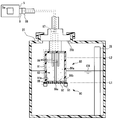
- the concentration measuring device 80 includes a measuring unit 80a and a cooling unit 90.
- the measurement unit 80 a includes a housing 81, an electrode 84, a main body connection unit 88, a permeable membrane 86 and an internal liquid 83.
- the housing 81 is a container-like member provided with a recess 81a.
- a plurality of electrodes 84 are spaced apart from each other inside the recess 81a.
- the plurality of electrodes 84 are electrically connected to the electrical contacts 9 of the endoscope reprocessor 1a via the electric cable 87 and the main body connecting portion 88. That is, the concentration measuring device 80 is electrically connected to the control unit 5 of the endoscope reprocessor 1.
- the control device of the concentration measuring device 80 is included in the control unit 5.
- the electrical contact 9 and the holding portion 20b are provided apart from each other, but the electrical contact 9 may be provided so as to be exposed from the holding portion 20b.
- the main body connecting portion 88 is provided at a location where the main body connecting portion 88 contacts the electrical contact 9 provided on the holding portion 20b of the concentration measuring device 80.
- the opening of the recess 81 a is covered with a permeable membrane 86.
- an internal liquid 83 is stored inside the recess 81a.
- the discharge surface 86 b exposed inside the recess 81 a of the osmotic membrane 86 is in contact with the internal liquid 83.
- the plurality of electrodes 84 are immersed in the internal liquid 83 in the recess 81a.
- the measurement surface 86a is the surface of the osmotic membrane 86 opposite to the discharge surface 86b. That is, when the concentration measuring device 80 measures the concentration of the measurement target liquid 100, the osmotic membrane 86 is a member arranged so as to separate the internal liquid 83 and the measurement target liquid 100.
- FIG. 3 is a diagram schematically showing a state where the measurement target passes through the osmotic membrane 86.
- FIG. 3 shows a case where the measurement target liquid 100 is in contact with the measurement surface 86a and the measurement surface 86a side of the osmotic membrane 86 is in a wet state. Further, in the state shown in FIG. 3, the concentration of the measurement target in the measurement target liquid 100 is higher than the concentration of the measurement target in the internal liquid 83.
- the osmotic membrane 86 is a porous membrane that does not allow liquid molecules to pass but allows gas molecules to pass.
- a release layer 86c including a release surface 86a in contact with the internal liquid 83
- a measurement layer 86d including a measurement surface 86a in contact with the measurement target liquid 100
- Layer 86e is present.
- the internal liquid 83 Since the internal liquid 83 is always stored in the recess 81a, the internal liquid 83 permeates the release layer 86c. Further, the measurement target liquid 100 penetrates into the measurement layer 86d. The measurement target in the measurement target liquid 100 penetrating into the measurement layer 86d becomes a gas molecule, passes through the dry layer 86e, and then dissolves in the internal liquid 83 penetrating into the release layer 86c. Then, the measurement object dissolved in the internal liquid 83 is discharged from the discharge surface 86a into the internal liquid 83 in the recess 81a.
- the concentration of the measurement target in the internal liquid 83 is higher than the concentration of the measurement target in the measurement target liquid 100, the measurement target in the internal liquid 83 passes through the osmotic membrane 86. It moves into the liquid 100 to be measured.
- the measurement layer 86d when the measurement layer 86d is in a wet state and the measurement target liquid 100 is in contact with the measurement surface 86a, the measurement layer 86d is in contact with the measurement target liquid 100 in contact with the measurement surface 86a.
- the concentration of the measurement target in the internal liquid 83 changes.
- the potential difference generated between the plurality of electrodes 84 or the current value flowing between the pair of electrodes 84 changes.
- the internal liquid 83 is disposed between the electrode 84 and the osmotic membrane 86 inside the recess 81 a of the housing 81 of the concentration measuring device 80, and the electrode 84 and the osmotic membrane 86 are connected by the internal liquid 83. It is in the state.
- “connect” refers to a state in which ions to be measured that have passed through the osmotic membrane 86 and reached the internal liquid 83 can reach the electrode 84 using the internal liquid 83 as a medium.
- the concentration measuring device 80 measures a change in potential difference generated between the plurality of electrodes 84 of the measurement unit 80a or a change in a current value flowing between the plurality of electrodes 84, and is in contact with the measurement surface 86a based on the measured value.
- the concentration of the measurement target in the measurement target liquid 100 is measured. Since the principle and configuration of concentration measurement in such a concentration measuring apparatus 80 are well known, detailed description thereof will be omitted.
- the holding portion 20b of the tank 20 detachably holds the housing 81 in the tank 20 so that the measurement surface 86a of the osmotic membrane 86 contacts the measurement target liquid 100.
- the measurement surface 86a of the concentration measuring device 80 held by the holding unit 20b is disposed at a predetermined first water level L1 in the tank 20. Accordingly, if the measurement target liquid 100 is stored up to a predetermined first water level L1 or higher in the tank 20, the osmotic membrane 86 is immersed in the measurement target liquid 100, and the measurement target liquid 100 comes into contact with the measurement surface 86a.
- a part of the housing 81 held by the holding portion 20 b may be exposed outside the tank 20.
- the water level sensor 55 detects the height of the liquid level stored in the tank 20.
- the water level sensor 55 is electrically connected to the control unit 5 and outputs detection result information to the control unit 5.
- the water level sensor 55 detects at least whether or not the liquid level in the tank 20 has reached the first water level L1.
- the water level sensor 55 when mixing the stock solution of the measurement target liquid supplied from the measurement target liquid bottle 18 and the water supplied from the dilution pipe in the tank 20, sets the volume ratio of both to a predetermined value. May be used.
- the configuration of the water level sensor 55 is not particularly limited.
- the water level sensor 55 includes, for example, a plurality of electrodes that are spaced apart from each other, and based on the presence or absence of electrical continuity between the plurality of electrodes that varies depending on whether or not the plurality of electrodes are submerged in the liquid.
- a so-called electrode-type water level sensor that detects whether or not the liquid level has reached a predetermined water level may be used.
- the water level sensor 55 detects whether or not the liquid level of the measurement target liquid has reached a predetermined water level based on the operating state of a switch that opens and closes according to the vertical movement of the float floating in the measurement target liquid.
- a so-called float type water level sensor may be used.
- the cooling unit 90 cools the liquid penetrating at least the measurement layer 86d of the osmotic membrane 86 to a solidification temperature or lower.
- the cooling unit 90 is electrically connected to the control unit 5. The operation of the cooling unit 90 is controlled by the control unit 5.
- the cooling unit 90 may be configured to cool the liquid that has permeated the measurement layer 86d to, for example, the solidification temperature or lower by cooling a member that is in direct contact with the measurement layer 86d.
- the configuration may be such that the liquid that permeates the measurement layer 86d is cooled to a solidification temperature or lower by cooling the gas that contacts the measurement surface 86b of the film 86.
- the cooling unit 90 includes a Peltier element 91, and cools the liquid penetrating the measurement layer 86d by driving the Peltier element 91.
- the cooling unit 90 of the present embodiment includes a heat transfer unit 92 that transfers heat from the measurement layer 86 d to the Peltier element 91.
- the heat transfer section 92 connects the liquid that has permeated the measurement layer 86d and the heat absorption section of the Peltier element 91.
- the heat transfer unit 92 is a metal mesh member that contacts the measurement surface 86d.
- the mesh-like member is not limited to a member in a form in which a linear member is knitted, and includes a member in a form in which a plurality of through holes are provided in a plate-like member.
- the material constituting the heat transfer section 92 is preferably a material that has corrosion resistance to the liquid 100 to be measured, such as stainless steel, and has high thermal conductivity. As shown in FIG. 2, the heat transfer unit 92 may be disposed in contact with the measurement surface 86 b or may be embedded in the measurement layer 91. Since the heat transfer part 92 has a structure in which a liquid passage part such as a mesh is formed, it does not hinder the permeation of the osmotic membrane 86 to be measured.
- the Peltier element 91 By driving the Peltier element 91, the heat of the measurement layer 86 d is transmitted through the heat transfer section 92 and released from the heat generating section of the Peltier element 91. If the Peltier element 91 is driven when a liquid 100 such as the measurement target liquid 100 or water penetrates the measurement layer 86d of the osmotic membrane 86, the liquid penetrating the measurement layer 86d is cooled to below the solidification temperature and solidified. To do.
- the concentration measuring device 80 configured as described above penetrates the measurement layer 86d by driving the cooling unit 90 continuously or intermittently while the measurement surface 86b of the osmotic membrane 86 is exposed to the air.
- the liquid is cooled and solidified.
- the timing of a cooling start is not specifically limited, It is preferable to start cooling before the measurement surface 86b is exposed in the air and in the stage immersed in the liquid.
- a dry layer 86e containing a gas is interposed between the measurement layer 86d and the release layer 86c. Due to the presence of the dry layer 86e, the heat transfer rate between the measurement layer 86d and the release layer 86c is reduced, and therefore, when the measurement layer 86d is cooled by the cooling unit 90, the temperature drop of the internal liquid 83 is prevented, The temperature of the internal liquid 83 can be kept within a temperature range in which concentration measurement can be performed.
- the liquid penetrating the measurement layer 86d when driving the cooling unit 90 is not limited to the measurement target liquid 100, and may be water.
- the liquid penetrating the measurement layer 86 d is the measurement target liquid 100.
- the water supplied from the water supply source 49 is introduced into the tank 20 and the inside of the tank 20 is rinsed.
- the liquid penetrating into the water is water.
- the concentration measuring device 80 stops the cooling unit 90 when performing concentration measurement. As described above, since only the liquid that permeates the measurement layer 86d of the membrane-like osmotic membrane 86 is solidified by the driving of the cooling unit 90, the amount of heat necessary to melt the liquid is small. is there.
- the measurement surface 86b of the osmotic membrane 86 is in a wet state where concentration measurement by the concentration measurement device 80 can be performed.
- the concentration measuring device 80 of the present embodiment allows the liquid permeating the measurement layer 86d by driving the cooling unit 90 when the measurement surface 86b is exposed to the air. By solidifying, the evaporation of the liquid from the measurement layer 86d can be prevented, and the amount of water in the measurement layer 86d can be maintained. Therefore, the concentration measuring apparatus 80 of the present embodiment can execute the concentration measurement of the measurement target liquid 100 without delay by preventing the osmotic membrane 86 from drying.
- the water level sensor 55 detects that the liquid is not stored up to the first water level L1 in the tank 20. That is.
- control unit 5 of the endoscope reprocessor 1 of the present embodiment uses the cooling unit 90 when the water level sensor 55 detects that no liquid is stored up to the first water level L1 in the tank 20.
- the cooling unit 90 is controlled to stop.
- the endoscope reprocessor 1 of the present embodiment can prevent the drying of the osmotic membrane 86 of the concentration measuring device 80 and execute the concentration measurement of the measurement target liquid 100 without delay.
- the measurement target liquid 100 when the measurement target liquid 100 is discharged from the tank 20 on the weekend and a new measurement target liquid unused on weekdays is supplied into the tank 20, the measurement target liquid 100 remains in the tank 20 for a long period of time. Even if the measurement surface 86b of the osmotic membrane 86 does not exist and is exposed to the air for a long time, the measurement target liquid 100 is supplied into the tank 20 in the endoscope reprocessor 1 of the present embodiment. Later, the concentration measurement of the measurement target liquid 100 by the concentration measuring device 80 can be performed without delay, and the subsequent regeneration process can be started.
- the concentration measuring device 80 of the present embodiment may include a heat transfer unit that transfers the heat of the heat generation unit of the Peltier element 91 to the internal liquid 83 in the housing 81.
- the concentration measuring device 80 of the present embodiment may include a heat transfer unit that transfers the heat of the heat generation unit of the Peltier element 91 to the internal liquid 83 in the housing 81.
- the Peltier element 91 by driving the Peltier element 91, the liquid penetrating the measurement layer 86d can be cooled and solidified, and the internal liquid 83 can be prevented from being lowered by applying heat to the internal liquid 83.
- the cooling unit 90 of this embodiment includes a heat pump 93.
- the heat pump 93 moves heat from the heat absorbing portion 93f to the heat generating portion 93g using a heat medium.
- the heat absorption part 93f is in contact with the heat transfer part 92 that transfers heat from the measurement layer 86d to the Peltier element 91.
- the endothermic portion 93f may be in contact with the measurement surface 86b of the osmotic membrane 86, or may be embedded in the measurement layer 86d of the osmotic membrane 86. Also good.
- the heat generating part 93g transmits heat to the internal liquid 83.
- the heat generating portion 93 g is disposed in the recess 81 a of the housing 81.
- the heat generating part 93g is disposed outside the housing 81, and the heat of the heat generating part 83g is transmitted to the internal liquid 83 via the heat transfer part contacting the heat generating part 83g and the internal liquid 83. May be.
- the heat pump 93 includes an evaporator 93a disposed in the heat absorbing section 93f, a condenser 93b disposed in the heat generating section 93g, a compressor 93c that connects the evaporator 93a and the condenser 93b, and an expansion valve 93d that connects the condenser 93b and the evaporator 93a. Is provided. Since the heat pump 93 is a well-known technique, a detailed description thereof is omitted.
- the heat of the measurement layer 86d is transmitted to the internal liquid 83 through the heat transfer section 92 and the heat pump 93 by driving the heat pump 93.
- the concentration measuring device 80 of the present embodiment cools and solidifies the liquid permeating the measurement layer 86d by driving the heat pump 93, and applies heat to the internal liquid 83 to thereby increase the temperature of the internal liquid 83. Can be prevented, and the temperature of the internal liquid 83 can be reliably maintained within a temperature range in which concentration measurement can be performed.
- the operations of the concentration measuring device 80 and the endoscope reprocessor 1 are the same as those in the first embodiment. Therefore, when the measurement surface 86b is exposed to the air, the concentration measurement device 80 and the endoscope reprocessor 1 according to this embodiment penetrate the measurement layer 86d by driving the cooling unit 90. The liquid can be solidified to prevent evaporation of the liquid from the measurement layer 86d, and the amount of water in the measurement layer 86d can be maintained. Therefore, the concentration measuring apparatus 80 of the present embodiment can execute the concentration measurement of the measurement target liquid 100 without delay by preventing the osmotic membrane 86 from drying.
- the present invention it is possible to realize a concentration measuring device and an endoscope reprocessor capable of preventing concentration of a osmotic membrane and performing concentration measurement without delay.
Landscapes
- Health & Medical Sciences (AREA)
- Life Sciences & Earth Sciences (AREA)
- Chemical & Material Sciences (AREA)
- General Health & Medical Sciences (AREA)
- Pathology (AREA)
- Physics & Mathematics (AREA)
- Chemical Kinetics & Catalysis (AREA)
- Molecular Biology (AREA)
- Electrochemistry (AREA)
- Analytical Chemistry (AREA)
- Biochemistry (AREA)
- General Physics & Mathematics (AREA)
- Immunology (AREA)
- Veterinary Medicine (AREA)
- Surgery (AREA)
- Animal Behavior & Ethology (AREA)
- Public Health (AREA)
- Epidemiology (AREA)
- Biophysics (AREA)
- Nuclear Medicine, Radiotherapy & Molecular Imaging (AREA)
- Optics & Photonics (AREA)
- Radiology & Medical Imaging (AREA)
- General Chemical & Material Sciences (AREA)
- Engineering & Computer Science (AREA)
- Biomedical Technology (AREA)
- Heart & Thoracic Surgery (AREA)
- Medical Informatics (AREA)
- Endoscopes (AREA)
Abstract
Ce dispositif de mesure de concentration comprend : une unité de mesure; une partie de raccordement à un corps; et une unité de refroidissement. L'unité de mesure comprend : un boîtier présentement un évidement; une électrode qui est logée dans l'évidement; une membrane d'osmose qui recouvre l'évidement et comprend une couche de mesure présentant une surface de mesure qui est en contact avec un liquide à mesurer qui contient une cible de mesure, une couche d'émission présentant une surface d'émission depuis laquelle la cible de mesure qui a pénétré par la surface de mesure est émise dans le boîtier, et une couche sèche qui est placée entre la couche de mesure et la couche d'émission; et un liquide interne qui est placé de manière hermétique à l'intérieur du boîtier et relie l'électrode et la membrane d'osmose. La partie de raccordement à un corps permet de raccorder électriquement l'électrode à un corps de reprocesseur d'endoscope. L'unité de refroidissement refroidit au moins un liquide, qui a pénétré dans la couche de mesure, à au moins la température de solidification.
Priority Applications (1)
| Application Number | Priority Date | Filing Date | Title |
|---|---|---|---|
| JP2016546112A JP6006465B1 (ja) | 2015-07-21 | 2016-03-24 | 濃度測定装置および内視鏡リプロセッサ |
Applications Claiming Priority (2)
| Application Number | Priority Date | Filing Date | Title |
|---|---|---|---|
| JP2015-144146 | 2015-07-21 | ||
| JP2015144146 | 2015-07-21 |
Publications (1)
| Publication Number | Publication Date |
|---|---|
| WO2017013905A1 true WO2017013905A1 (fr) | 2017-01-26 |
Family
ID=57834255
Family Applications (1)
| Application Number | Title | Priority Date | Filing Date |
|---|---|---|---|
| PCT/JP2016/059495 WO2017013905A1 (fr) | 2015-07-21 | 2016-03-24 | Dispositif de mesure de concentration et reprocesseur pour endoscope |
Country Status (1)
| Country | Link |
|---|---|
| WO (1) | WO2017013905A1 (fr) |
Citations (6)
| Publication number | Priority date | Publication date | Assignee | Title |
|---|---|---|---|---|
| JPS5643554A (en) * | 1979-09-19 | 1981-04-22 | Toshiba Corp | Electrode having semipermeable membrane |
| JPS58196451A (ja) * | 1982-05-13 | 1983-11-15 | Fujikura Ltd | 酸素濃度測定器 |
| JP2010057792A (ja) * | 2008-09-05 | 2010-03-18 | Fujifilm Corp | 内視鏡洗浄消毒装置 |
| JP2013064702A (ja) * | 2011-09-20 | 2013-04-11 | Hitachi Maxell Ltd | 電極保護体 |
| JP5826982B1 (ja) * | 2014-09-04 | 2015-12-02 | オリンパス株式会社 | 電極式溶液測定装置、貯留容器、および内視鏡リプロセッサ |
| JP5893817B1 (ja) * | 2014-11-18 | 2016-03-23 | オリンパス株式会社 | 濃度計及び内視鏡リプロセッサ |
-
2016
- 2016-03-24 WO PCT/JP2016/059495 patent/WO2017013905A1/fr active Application Filing
Patent Citations (6)
| Publication number | Priority date | Publication date | Assignee | Title |
|---|---|---|---|---|
| JPS5643554A (en) * | 1979-09-19 | 1981-04-22 | Toshiba Corp | Electrode having semipermeable membrane |
| JPS58196451A (ja) * | 1982-05-13 | 1983-11-15 | Fujikura Ltd | 酸素濃度測定器 |
| JP2010057792A (ja) * | 2008-09-05 | 2010-03-18 | Fujifilm Corp | 内視鏡洗浄消毒装置 |
| JP2013064702A (ja) * | 2011-09-20 | 2013-04-11 | Hitachi Maxell Ltd | 電極保護体 |
| JP5826982B1 (ja) * | 2014-09-04 | 2015-12-02 | オリンパス株式会社 | 電極式溶液測定装置、貯留容器、および内視鏡リプロセッサ |
| JP5893817B1 (ja) * | 2014-11-18 | 2016-03-23 | オリンパス株式会社 | 濃度計及び内視鏡リプロセッサ |
Similar Documents
| Publication | Publication Date | Title |
|---|---|---|
| ES2203505T3 (es) | Sintesis electrolitica de acido peracetico. | |
| WO2016194449A1 (fr) | Dispositif de retraitement d'endoscope | |
| JP5966095B1 (ja) | 内視鏡リプロセッサ | |
| US10219684B2 (en) | Endoscope reprocessor | |
| JP6006465B1 (ja) | 濃度測定装置および内視鏡リプロセッサ | |
| WO2017013905A1 (fr) | Dispositif de mesure de concentration et reprocesseur pour endoscope | |
| JP6006462B1 (ja) | 内視鏡リプロセッサ | |
| JP6122227B1 (ja) | 内視鏡リプロセッサ | |
| JP2013091039A (ja) | 強酸性水生成装置 | |
| JP6017744B1 (ja) | 内視鏡リプロセッサ | |
| JP6033518B1 (ja) | 内視鏡リプロセッサ | |
| WO2017013906A1 (fr) | Retraiteur d'endoscope | |
| JPWO2016194596A1 (ja) | 内視鏡リプロセッサ | |
| JP6006466B1 (ja) | 内視鏡リプロセッサ | |
| JP3566632B2 (ja) | 内視鏡洗浄装置 | |
| WO2017064963A1 (fr) | Dispositif de retraitement d'endoscope | |
| US9993144B2 (en) | Control method for endoscope reprocessor | |
| JP6495558B1 (ja) | 内視鏡再生処理方法および内視鏡リプロセッサ | |
| JP2018075168A (ja) | 内視鏡リプロセッサおよび内視鏡リプロセス方法 | |
| JP2017055893A (ja) | 内視鏡リプロセッサ | |
| JP2009189413A (ja) | 内視鏡洗浄消毒装置 |
Legal Events
| Date | Code | Title | Description |
|---|---|---|---|
| ENP | Entry into the national phase |
Ref document number: 2016546112 Country of ref document: JP Kind code of ref document: A |
|
| 121 | Ep: the epo has been informed by wipo that ep was designated in this application |
Ref document number: 16827470 Country of ref document: EP Kind code of ref document: A1 |
|
| NENP | Non-entry into the national phase |
Ref country code: DE |
|
| 122 | Ep: pct application non-entry in european phase |
Ref document number: 16827470 Country of ref document: EP Kind code of ref document: A1 |