WO2017013905A1 - Concentration measurement device and endoscope reprocessor - Google Patents
Concentration measurement device and endoscope reprocessor Download PDFInfo
- Publication number
- WO2017013905A1 WO2017013905A1 PCT/JP2016/059495 JP2016059495W WO2017013905A1 WO 2017013905 A1 WO2017013905 A1 WO 2017013905A1 JP 2016059495 W JP2016059495 W JP 2016059495W WO 2017013905 A1 WO2017013905 A1 WO 2017013905A1
- Authority
- WO
- WIPO (PCT)
- Prior art keywords
- measurement
- liquid
- layer
- tank
- measurement target
- Prior art date
Links
Images


Classifications
-
- A—HUMAN NECESSITIES
- A61—MEDICAL OR VETERINARY SCIENCE; HYGIENE
- A61B—DIAGNOSIS; SURGERY; IDENTIFICATION
- A61B1/00—Instruments for performing medical examinations of the interior of cavities or tubes of the body by visual or photographical inspection, e.g. endoscopes; Illuminating arrangements therefor
- A61B1/12—Instruments for performing medical examinations of the interior of cavities or tubes of the body by visual or photographical inspection, e.g. endoscopes; Illuminating arrangements therefor with cooling or rinsing arrangements
-
- A—HUMAN NECESSITIES
- A61—MEDICAL OR VETERINARY SCIENCE; HYGIENE
- A61L—METHODS OR APPARATUS FOR STERILISING MATERIALS OR OBJECTS IN GENERAL; DISINFECTION, STERILISATION OR DEODORISATION OF AIR; CHEMICAL ASPECTS OF BANDAGES, DRESSINGS, ABSORBENT PADS OR SURGICAL ARTICLES; MATERIALS FOR BANDAGES, DRESSINGS, ABSORBENT PADS OR SURGICAL ARTICLES
- A61L2/00—Methods or apparatus for disinfecting or sterilising materials or objects other than foodstuffs or contact lenses; Accessories therefor
- A61L2/16—Methods or apparatus for disinfecting or sterilising materials or objects other than foodstuffs or contact lenses; Accessories therefor using chemical substances
- A61L2/18—Liquid substances or solutions comprising solids or dissolved gases
-
- G—PHYSICS
- G01—MEASURING; TESTING
- G01N—INVESTIGATING OR ANALYSING MATERIALS BY DETERMINING THEIR CHEMICAL OR PHYSICAL PROPERTIES
- G01N27/00—Investigating or analysing materials by the use of electric, electrochemical, or magnetic means
- G01N27/26—Investigating or analysing materials by the use of electric, electrochemical, or magnetic means by investigating electrochemical variables; by using electrolysis or electrophoresis
- G01N27/28—Electrolytic cell components
- G01N27/30—Electrodes, e.g. test electrodes; Half-cells
- G01N27/333—Ion-selective electrodes or membranes
-
- G—PHYSICS
- G01—MEASURING; TESTING
- G01N—INVESTIGATING OR ANALYSING MATERIALS BY DETERMINING THEIR CHEMICAL OR PHYSICAL PROPERTIES
- G01N27/00—Investigating or analysing materials by the use of electric, electrochemical, or magnetic means
- G01N27/26—Investigating or analysing materials by the use of electric, electrochemical, or magnetic means by investigating electrochemical variables; by using electrolysis or electrophoresis
- G01N27/403—Cells and electrode assemblies
- G01N27/404—Cells with anode, cathode and cell electrolyte on the same side of a permeable membrane which separates them from the sample fluid, e.g. Clark-type oxygen sensors
-
- G—PHYSICS
- G01—MEASURING; TESTING
- G01N—INVESTIGATING OR ANALYSING MATERIALS BY DETERMINING THEIR CHEMICAL OR PHYSICAL PROPERTIES
- G01N27/00—Investigating or analysing materials by the use of electric, electrochemical, or magnetic means
- G01N27/26—Investigating or analysing materials by the use of electric, electrochemical, or magnetic means by investigating electrochemical variables; by using electrolysis or electrophoresis
- G01N27/416—Systems
Definitions
- the present invention relates to a concentration measuring device using an osmotic membrane and an endoscope reprocessor.
- Endoscopes used in the medical field are subjected to regeneration processing using chemicals such as cleaning and disinfection after use.
- An endoscope reprocessor that automatically performs endoscope reproduction processing is also known.
- Japanese Patent Application Laid-Open No. 2010-57992 discloses an endoscope reprocessor including a concentration measurement device that measures the concentration of a measurement target solution that is a chemical solution used for regeneration processing.
- a concentration measuring device a device using a permeable membrane that transmits a specific ion in a liquid to be measured is known.
- the measurement surface which is a part where the permeable membrane is provided, is brought into contact with the liquid to be measured.
- a concentration measurement device using an osmosis membrane when the measurement surface in contact with the measurement target liquid is in a dry state at the time of concentration measurement, the measurement surface is in contact with the measurement target liquid compared to when the measurement surface is in a wet state. After that, a longer waiting time is required until a correct measurement result is obtained.
- the present invention solves the above-described problems, and an object thereof is to provide a concentration measuring apparatus and an endoscope reprocessor capable of performing concentration measurement without delay by preventing drying of the osmotic membrane. .
- a concentration measuring device includes a housing having a recess, an electrode accommodated in the recess, a measurement layer including a measurement surface in contact with a measurement target liquid containing the measurement target, and the measurement surface.
- An osmosis membrane including an emission layer including an emission surface for emitting an intruding measurement object into the housing, and a dry layer sandwiched between the measurement layer and the emission layer, and enclosing in the housing
- a measuring unit including an internal liquid connecting the electrode and the osmotic membrane, a main body connecting unit for electrically connecting the electrode to an endoscope reprocessor main body, and penetrating at least the measuring layer
- a cooling unit that cools the liquid being cooled to a solidification temperature or lower.
- An endoscope reprocessor holds the housing such that the concentration measuring device, a tank that stores a liquid to be measured, and the permeable membrane are immersed in the liquid to be measured in the tank.
- a holding unit that performs electrical contact with the main body connection unit.
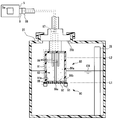
- An endoscope reprocessor 1 shown in FIG. 1 is a device that performs a reproduction process on an endoscope.
- the regeneration treatment here is not particularly limited, and is a rinsing treatment with water, a washing treatment for removing dirt such as organic matter, a disinfection treatment for invalidating predetermined microorganisms, a sterilization treatment for eliminating or killing all microorganisms, Or any combination thereof may be used.
- upper refers to a position that is further away from the ground relative to the comparison target
- lower refers to a position that is closer to the ground relative to the comparison target.
- the height in the following description shall show the height relationship along the gravity direction.
- the endoscope reprocessor 1 includes a control unit 5, a power supply unit 6, a processing tank 2, a tank 20, a holding unit 20b, and an electrical contact 9 arranged in the endoscope reprocessor main body 1a. It is installed and configured.
- a measuring unit 80 a of the concentration measuring device 80 is detachably held by the holding unit 20 b in the tank 20, and a main body connecting unit 88 of the concentration measuring device 80 is connected to the electrical contact 9.
- the control unit 5 can be configured to include an arithmetic device (CPU), a storage device (RAM), an auxiliary storage device, an input / output device, a power control device, and the like, and each part constituting the endoscope reprocessor 1 The operation is controlled based on a predetermined program.
- the control unit 5 includes a determination unit 5a that executes a determination process described later. The operation of each component included in the endoscope reprocessor 1 in the following description is controlled by the control unit 5 even when not specifically described.
- the power supply unit 6 supplies power to each part of the endoscope reprocessor 1.
- the power supply unit 6 distributes electric power obtained from the outside such as a commercial power supply to each part.
- the power supply unit 6 may include a power generation device or a battery.
- the treatment tank 2 has a concave shape having an opening, and can store liquid therein.
- An endoscope (not shown) can be disposed in the processing tank 2.
- a lid 3 that opens and closes an opening of the processing tank 2 is provided in the upper part of the processing tank 2. When the endoscope is subjected to a regeneration process in the processing tank 2, the opening of the processing tank 2 is closed by the lid 3.
- the treatment tank 2 is provided with a measurement target liquid nozzle 12, a drain port 11, a circulation port 13, a circulation nozzle 14, a cleaning liquid nozzle 15, an endoscope connection part 16, and an accessory case 17.
- the measurement target liquid nozzle 12 is an opening that communicates with the tank 20 via the measurement target liquid conduit 26.
- the tank 20 stores the measurement target liquid 100.
- a measuring unit 80 a and a water level sensor 55 of the concentration measuring device 80 are arranged. The concentration measuring device 80 and the water level sensor 55 will be described later.
- the measurement target liquid pipe 26 is provided with a measurement target liquid pump 27. By operating the measurement target liquid pump 27, the measurement target liquid 100 in the tank 20 is transferred into the processing tank 2 via the measurement target liquid conduit 26 and the measurement target liquid nozzle 12.
- the type of the measurement target liquid 100 stored in the tank 20 is not particularly limited.
- the measurement target liquid 100 is used for disinfection, such as a peracetic acid-containing liquid containing peracetic acid. Disinfectant.
- the present invention is not limited to this, and as the measurement target liquid 100, a cleaning liquid used for cleaning processing, a highly volatile solution used for drying, and the like can be appropriately selected according to the purpose.
- the measurement target liquid 100 is obtained by diluting the stock solution of the measurement target liquid supplied from the measurement target liquid bottle 18 with water at a predetermined ratio.
- a bottle connection unit 19 that introduces the stock solution of the measurement target liquid supplied from the measurement target liquid bottle 18 into the tank 20, and a dilution pipe 48 that introduces dilution water into the tank 20. Communicating with By connecting the measurement target liquid bottle 18 to the bottle connecting portion 19, the stock solution of the measurement target liquid is introduced into the tank 20.
- a configuration for introducing water from the dilution pipe 48 into the tank 20 will be described later.
- the endoscope reprocessor 1 does not have to have a configuration in which the liquid to be measured is diluted with water or the like. Further, when the measurement target liquid is used by mixing a plurality of types of stock solutions, the bottle connection unit 19 can be connected to a plurality of measurement target liquid bottles 18.
- the measurement target liquid 100 can be reused when the concentration is within a predetermined range having medicinal effects.
- the tank 20 also serves as a measurement target liquid recovery unit 29 that recovers and stores the measurement target liquid 100 transferred from the tank 20 into the processing tank 2.
- the tank 20 and the measurement target liquid recovery unit 29 are simply referred to as the tank 20.
- the tank 20 may be provided separately from the measurement target liquid recovery unit 29.
- the volume of the tank 20 may be smaller than that of the measurement target liquid recovery unit 29.
- the tank 20 is provided with a drainage part 28.
- the drainage unit 28 discharges a liquid to be measured or a liquid such as water from the tank 20.
- the drainage unit 28 may be configured to discharge the liquid from the tank 20 by gravity, or may be configured to forcibly discharge the liquid from the tank 20 by a pump.
- the drainage unit 28 includes a drain line 28a that communicates with a drainage port 20a provided at or near the bottom of the tank 20, and a drain valve 28b that opens and closes the drain line 28a.
- the drain valve 28b may be an electromagnetic opening / closing valve whose opening / closing is controlled by the controller 5, or a cock that is opened / closed by a user's manual operation.
- the path for discharging the liquid from the tank 20 is not limited to the drain line 28a.
- the liquid can be discharged from the tank 20 into the processing tank 2 via the measurement target liquid pipe 26 and the measurement target liquid nozzle 12. .
- the drainage port 11 is an opening provided at the lowest position in the treatment tank 2.
- the drainage port 11 is connected to the discharge pipe 21.
- the drain line 21 communicates the drain port 11 and the switching valve 22.
- a recovery conduit 23 and a waste conduit 25 are connected to the switching valve 22.
- the switching valve 22 can be switched to a state in which the discharge conduit 21 is closed, a state in which the discharge conduit 21 and the recovery conduit 23 are in communication, or a state in which the discharge conduit 21 and the waste conduit 25 are in communication. .
- the recovery line 23 communicates the tank 20 and the switching valve 22. Further, a discharge pump 24 is provided in the waste pipe 25. The waste line 25 is connected to a drainage facility for receiving the liquid discharged from the endoscope reprocessor 1.
- the liquid can be stored in the treatment tank 2. Further, when the measurement target liquid is stored in the processing tank 2, the measurement target liquid is transferred from the processing tank 2 to the tank 20 by setting the switching valve 22 in a state where the discharge pipe 21 and the recovery pipe 23 communicate with each other. Be transported. Further, when the switching valve 22 is in a state where the discharge pipe 21 and the waste pipe 25 are communicated and the operation of the discharge pump 24 is started, the liquid in the processing tank 2 is drained via the waste pipe 25. Is sent out.
- the circulation port 13 is an opening provided near the bottom surface of the processing tank 2.
- the circulation port 13 communicates with the circulation conduit 13a.
- the circulation line 13 a is branched into two lines, that is, an endoscope circulation line 30 and a processing tank circulation line 40.
- the endoscope circulation line 30 communicates the circulation line 13a with a channel valve 32 described later.
- a circulation pump 33 is provided in the endoscope circulation conduit 30. The circulation pump 33 operates to transfer the fluid in the endoscope circulation conduit 30 toward the channel valve 32.
- the channel valve 32 is connected to an intake pipe 34, an alcohol pipe 38, and a delivery pipe 31 in addition to the endoscope circulation pipe 30 described above.
- the channel valve 32 selectively connects any one of the endoscope circulation conduit 30, the intake conduit 34, and the alcohol conduit 38 to the delivery conduit 31.
- the intake pipe 34 has one end open to the atmosphere and the other end connected to the channel valve 32. Although not shown, a filter for filtering the passing gas is provided at one end of the intake pipe 34.
- the air pump 35 is provided in the intake pipe 34 and moves the gas in the intake pipe 34 toward the channel valve 32 by operating.
- the alcohol pipe line 38 communicates the alcohol tank 37 that stores alcohol and the channel valve 32.
- Examples of the alcohol stored in the alcohol tank 37 include ethanol. About alcohol concentration, it can select suitably.
- the alcohol pump 39 is provided in the alcohol pipe line 38 and moves the alcohol in the alcohol tank 37 toward the channel valve 32 by operating.
- the processing valve 2 can be obtained by setting the channel valve 32 in a state where the delivery pipe line 31 and the endoscope circulation pipe 30 are in communication with each other and the operation of the circulation pump 33 is started.
- the liquid inside is sent to the delivery line 31 via the circulation port 13, the circulation line 13 a and the endoscope circulation line 30.
- the channel valve 32 when the channel valve 32 is brought into a state where the delivery line 31 and the intake line 34 are in communication with each other and the operation of the air pump 35 is started, air is sent into the delivery line 31. Further, when the channel valve 32 is brought into a state where the delivery pipe line 31 and the alcohol pipe line 38 are in communication with each other and the operation of the alcohol pump 39 is started, the alcohol in the alcohol tank 37 is fed into the delivery pipe line 31.
- the delivery pipeline 31 is branched into an endoscope connection pipeline 31b and a case connection pipeline 31c.
- the endoscope connection pipe line 31 b is connected to the endoscope connection unit 16.
- the case connection pipe line 31 c is connected to the accessory case 17.
- the delivery pipe line 31 is provided with a flow path switching unit 31a.
- the flow path switching unit 31a can switch whether the fluid sent from the channel valve 32 to the delivery pipe line 31 is allowed to flow to the endoscope connection pipe line 31b or the case connection pipe line 31c. In addition, you may control so that the pressure by the side of the endoscope connection pipe line 31b may become fixed at the time of switching.
- the endoscope connection unit 16 is connected to a base provided in the endoscope through an endoscope tube (not shown).
- the accessory case 17 is a cage member that accommodates an accessory (not shown) of the endoscope. Therefore, the fluid sent from the channel valve 32 to the delivery pipe line 31 is introduced into the mouthpiece of the endoscope or the accessory case 17.
- the treatment tank circulation line 40 communicates the circulation line 13a and the circulation nozzle 14 with each other.
- the circulation nozzle 14 is an opening provided in the processing tank 2.
- the treatment tank circulation pipe 40 is provided with a fluid pump 41.
- a three-way valve 42 is provided between the flowing liquid pump 41 and the circulation nozzle 14 in the treatment tank circulation line 40.
- a water supply pipeline 43 is connected to the three-way valve 42.
- the three-way valve 42 can be switched to a state where the circulation nozzle 14 and the treatment tank circulation line 40 are communicated with each other or a state where the circulation nozzle 14 and the water supply line 43 are communicated.
- the water supply pipe 43 communicates the three-way valve 42 and the water supply source connection 46.
- the water supply pipe 43 is provided with a water introduction valve 45 for opening and closing the water supply pipe 43 and a water filter 44 for filtering water.
- the water supply source connection unit 46 is connected to a water supply source 49 such as a water supply facility that sends out water through, for example, a hose.
- a dilution valve 47 is provided in a section of the water supply pipe 43 between the water filter 44 and the three-way valve 42.
- a dilution pipe 48 that connects the dilution valve 47 and the tank 20 is connected to the dilution valve 47.
- the dilution valve 47 can be switched between a state in which the water filter 44 and the three-way valve 42 are in communication with each other, or a state in which the water filter 44 and the dilution pipe 48 are in communication with each other.
- the three-way valve 42 When liquid is stored in the treatment tank 2, the three-way valve 42 is in a state where the circulation nozzle 14 and the treatment tank circulation pipe 40 are in communication, and the dilution valve 47 is in communication with the water filter 44 and the three-way valve 42. If the operation of the fluid pump 41 is started as a state, the liquid in the treatment tank 2 is discharged from the circulation nozzle 14 via the circulation port 13, the circulation line 13 a and the treatment tank circulation line 40.
- the dilution valve 47 is in a state in which the water filter 44 and the three-way valve 42 are in communication, and the water introduction valve 45 is opened.
- the water supplied from the water supply source 49 is discharged from the circulation nozzle 14.
- the liquid discharged from the circulation nozzle 14 is introduced into the processing tank 2.
- the cleaning liquid nozzle 15 is an opening communicating with the cleaning liquid tank 50 for storing the cleaning liquid through the cleaning liquid pipe 51.
- the cleaning liquid is used for the cleaning process.
- a cleaning liquid pump 52 is provided in the cleaning liquid pipe 51. By operating the cleaning liquid pump 52, the cleaning liquid in the cleaning liquid tank 50 is transferred into the processing tank 2.
- the endoscope reprocessor 1 includes an operation unit 7 and an output unit 8 that constitute a user interface that exchanges information with a user.
- the operation unit 7 and the output unit 8 are electrically connected to the control unit 5.
- the operation unit 7 includes operation members such as a push switch and a touch sensor.
- the output unit 8 includes, for example, a display device that displays images and characters, a light emitting device that emits light, a speaker that emits sound, or a combination thereof.
- the operation unit 7 and the output unit 8 may be provided in an electronic device that performs wireless communication with the control unit 5.
- the tank 20 is provided with a concentration measuring device 80 and a water level sensor 55.
- the tank 20 can store the liquid to be measured up to the second water level L2 higher than the predetermined first water level L1.
- the tank 20 includes a holding unit 20b that detachably holds the measuring unit 80a of the concentration measuring device 80.
- the concentration measuring device 80 measures the concentration of the measurement target contained in the measurement target liquid 100 in contact with the measurement surface 86a of the measurement unit 80a.
- the concentration measuring device 80 measures the concentration of peracetic acid ions that are the measurement target contained in the measurement target liquid 100.
- the concentration measuring device 80 includes a measuring unit 80a and a cooling unit 90.
- the measurement unit 80 a includes a housing 81, an electrode 84, a main body connection unit 88, a permeable membrane 86 and an internal liquid 83.
- the housing 81 is a container-like member provided with a recess 81a.
- a plurality of electrodes 84 are spaced apart from each other inside the recess 81a.
- the plurality of electrodes 84 are electrically connected to the electrical contacts 9 of the endoscope reprocessor 1a via the electric cable 87 and the main body connecting portion 88. That is, the concentration measuring device 80 is electrically connected to the control unit 5 of the endoscope reprocessor 1.
- the control device of the concentration measuring device 80 is included in the control unit 5.
- the electrical contact 9 and the holding portion 20b are provided apart from each other, but the electrical contact 9 may be provided so as to be exposed from the holding portion 20b.
- the main body connecting portion 88 is provided at a location where the main body connecting portion 88 contacts the electrical contact 9 provided on the holding portion 20b of the concentration measuring device 80.
- the opening of the recess 81 a is covered with a permeable membrane 86.
- an internal liquid 83 is stored inside the recess 81a.
- the discharge surface 86 b exposed inside the recess 81 a of the osmotic membrane 86 is in contact with the internal liquid 83.
- the plurality of electrodes 84 are immersed in the internal liquid 83 in the recess 81a.
- the measurement surface 86a is the surface of the osmotic membrane 86 opposite to the discharge surface 86b. That is, when the concentration measuring device 80 measures the concentration of the measurement target liquid 100, the osmotic membrane 86 is a member arranged so as to separate the internal liquid 83 and the measurement target liquid 100.
- FIG. 3 is a diagram schematically showing a state where the measurement target passes through the osmotic membrane 86.
- FIG. 3 shows a case where the measurement target liquid 100 is in contact with the measurement surface 86a and the measurement surface 86a side of the osmotic membrane 86 is in a wet state. Further, in the state shown in FIG. 3, the concentration of the measurement target in the measurement target liquid 100 is higher than the concentration of the measurement target in the internal liquid 83.
- the osmotic membrane 86 is a porous membrane that does not allow liquid molecules to pass but allows gas molecules to pass.
- a release layer 86c including a release surface 86a in contact with the internal liquid 83
- a measurement layer 86d including a measurement surface 86a in contact with the measurement target liquid 100
- Layer 86e is present.
- the internal liquid 83 Since the internal liquid 83 is always stored in the recess 81a, the internal liquid 83 permeates the release layer 86c. Further, the measurement target liquid 100 penetrates into the measurement layer 86d. The measurement target in the measurement target liquid 100 penetrating into the measurement layer 86d becomes a gas molecule, passes through the dry layer 86e, and then dissolves in the internal liquid 83 penetrating into the release layer 86c. Then, the measurement object dissolved in the internal liquid 83 is discharged from the discharge surface 86a into the internal liquid 83 in the recess 81a.
- the concentration of the measurement target in the internal liquid 83 is higher than the concentration of the measurement target in the measurement target liquid 100, the measurement target in the internal liquid 83 passes through the osmotic membrane 86. It moves into the liquid 100 to be measured.
- the measurement layer 86d when the measurement layer 86d is in a wet state and the measurement target liquid 100 is in contact with the measurement surface 86a, the measurement layer 86d is in contact with the measurement target liquid 100 in contact with the measurement surface 86a.
- the concentration of the measurement target in the internal liquid 83 changes.
- the potential difference generated between the plurality of electrodes 84 or the current value flowing between the pair of electrodes 84 changes.
- the internal liquid 83 is disposed between the electrode 84 and the osmotic membrane 86 inside the recess 81 a of the housing 81 of the concentration measuring device 80, and the electrode 84 and the osmotic membrane 86 are connected by the internal liquid 83. It is in the state.
- “connect” refers to a state in which ions to be measured that have passed through the osmotic membrane 86 and reached the internal liquid 83 can reach the electrode 84 using the internal liquid 83 as a medium.
- the concentration measuring device 80 measures a change in potential difference generated between the plurality of electrodes 84 of the measurement unit 80a or a change in a current value flowing between the plurality of electrodes 84, and is in contact with the measurement surface 86a based on the measured value.
- the concentration of the measurement target in the measurement target liquid 100 is measured. Since the principle and configuration of concentration measurement in such a concentration measuring apparatus 80 are well known, detailed description thereof will be omitted.
- the holding portion 20b of the tank 20 detachably holds the housing 81 in the tank 20 so that the measurement surface 86a of the osmotic membrane 86 contacts the measurement target liquid 100.
- the measurement surface 86a of the concentration measuring device 80 held by the holding unit 20b is disposed at a predetermined first water level L1 in the tank 20. Accordingly, if the measurement target liquid 100 is stored up to a predetermined first water level L1 or higher in the tank 20, the osmotic membrane 86 is immersed in the measurement target liquid 100, and the measurement target liquid 100 comes into contact with the measurement surface 86a.
- a part of the housing 81 held by the holding portion 20 b may be exposed outside the tank 20.
- the water level sensor 55 detects the height of the liquid level stored in the tank 20.
- the water level sensor 55 is electrically connected to the control unit 5 and outputs detection result information to the control unit 5.
- the water level sensor 55 detects at least whether or not the liquid level in the tank 20 has reached the first water level L1.
- the water level sensor 55 when mixing the stock solution of the measurement target liquid supplied from the measurement target liquid bottle 18 and the water supplied from the dilution pipe in the tank 20, sets the volume ratio of both to a predetermined value. May be used.
- the configuration of the water level sensor 55 is not particularly limited.
- the water level sensor 55 includes, for example, a plurality of electrodes that are spaced apart from each other, and based on the presence or absence of electrical continuity between the plurality of electrodes that varies depending on whether or not the plurality of electrodes are submerged in the liquid.
- a so-called electrode-type water level sensor that detects whether or not the liquid level has reached a predetermined water level may be used.
- the water level sensor 55 detects whether or not the liquid level of the measurement target liquid has reached a predetermined water level based on the operating state of a switch that opens and closes according to the vertical movement of the float floating in the measurement target liquid.
- a so-called float type water level sensor may be used.
- the cooling unit 90 cools the liquid penetrating at least the measurement layer 86d of the osmotic membrane 86 to a solidification temperature or lower.
- the cooling unit 90 is electrically connected to the control unit 5. The operation of the cooling unit 90 is controlled by the control unit 5.
- the cooling unit 90 may be configured to cool the liquid that has permeated the measurement layer 86d to, for example, the solidification temperature or lower by cooling a member that is in direct contact with the measurement layer 86d.
- the configuration may be such that the liquid that permeates the measurement layer 86d is cooled to a solidification temperature or lower by cooling the gas that contacts the measurement surface 86b of the film 86.
- the cooling unit 90 includes a Peltier element 91, and cools the liquid penetrating the measurement layer 86d by driving the Peltier element 91.
- the cooling unit 90 of the present embodiment includes a heat transfer unit 92 that transfers heat from the measurement layer 86 d to the Peltier element 91.
- the heat transfer section 92 connects the liquid that has permeated the measurement layer 86d and the heat absorption section of the Peltier element 91.
- the heat transfer unit 92 is a metal mesh member that contacts the measurement surface 86d.
- the mesh-like member is not limited to a member in a form in which a linear member is knitted, and includes a member in a form in which a plurality of through holes are provided in a plate-like member.
- the material constituting the heat transfer section 92 is preferably a material that has corrosion resistance to the liquid 100 to be measured, such as stainless steel, and has high thermal conductivity. As shown in FIG. 2, the heat transfer unit 92 may be disposed in contact with the measurement surface 86 b or may be embedded in the measurement layer 91. Since the heat transfer part 92 has a structure in which a liquid passage part such as a mesh is formed, it does not hinder the permeation of the osmotic membrane 86 to be measured.
- the Peltier element 91 By driving the Peltier element 91, the heat of the measurement layer 86 d is transmitted through the heat transfer section 92 and released from the heat generating section of the Peltier element 91. If the Peltier element 91 is driven when a liquid 100 such as the measurement target liquid 100 or water penetrates the measurement layer 86d of the osmotic membrane 86, the liquid penetrating the measurement layer 86d is cooled to below the solidification temperature and solidified. To do.
- the concentration measuring device 80 configured as described above penetrates the measurement layer 86d by driving the cooling unit 90 continuously or intermittently while the measurement surface 86b of the osmotic membrane 86 is exposed to the air.
- the liquid is cooled and solidified.
- the timing of a cooling start is not specifically limited, It is preferable to start cooling before the measurement surface 86b is exposed in the air and in the stage immersed in the liquid.
- a dry layer 86e containing a gas is interposed between the measurement layer 86d and the release layer 86c. Due to the presence of the dry layer 86e, the heat transfer rate between the measurement layer 86d and the release layer 86c is reduced, and therefore, when the measurement layer 86d is cooled by the cooling unit 90, the temperature drop of the internal liquid 83 is prevented, The temperature of the internal liquid 83 can be kept within a temperature range in which concentration measurement can be performed.
- the liquid penetrating the measurement layer 86d when driving the cooling unit 90 is not limited to the measurement target liquid 100, and may be water.
- the liquid penetrating the measurement layer 86 d is the measurement target liquid 100.
- the water supplied from the water supply source 49 is introduced into the tank 20 and the inside of the tank 20 is rinsed.
- the liquid penetrating into the water is water.
- the concentration measuring device 80 stops the cooling unit 90 when performing concentration measurement. As described above, since only the liquid that permeates the measurement layer 86d of the membrane-like osmotic membrane 86 is solidified by the driving of the cooling unit 90, the amount of heat necessary to melt the liquid is small. is there.
- the measurement surface 86b of the osmotic membrane 86 is in a wet state where concentration measurement by the concentration measurement device 80 can be performed.
- the concentration measuring device 80 of the present embodiment allows the liquid permeating the measurement layer 86d by driving the cooling unit 90 when the measurement surface 86b is exposed to the air. By solidifying, the evaporation of the liquid from the measurement layer 86d can be prevented, and the amount of water in the measurement layer 86d can be maintained. Therefore, the concentration measuring apparatus 80 of the present embodiment can execute the concentration measurement of the measurement target liquid 100 without delay by preventing the osmotic membrane 86 from drying.
- the water level sensor 55 detects that the liquid is not stored up to the first water level L1 in the tank 20. That is.
- control unit 5 of the endoscope reprocessor 1 of the present embodiment uses the cooling unit 90 when the water level sensor 55 detects that no liquid is stored up to the first water level L1 in the tank 20.
- the cooling unit 90 is controlled to stop.
- the endoscope reprocessor 1 of the present embodiment can prevent the drying of the osmotic membrane 86 of the concentration measuring device 80 and execute the concentration measurement of the measurement target liquid 100 without delay.
- the measurement target liquid 100 when the measurement target liquid 100 is discharged from the tank 20 on the weekend and a new measurement target liquid unused on weekdays is supplied into the tank 20, the measurement target liquid 100 remains in the tank 20 for a long period of time. Even if the measurement surface 86b of the osmotic membrane 86 does not exist and is exposed to the air for a long time, the measurement target liquid 100 is supplied into the tank 20 in the endoscope reprocessor 1 of the present embodiment. Later, the concentration measurement of the measurement target liquid 100 by the concentration measuring device 80 can be performed without delay, and the subsequent regeneration process can be started.
- the concentration measuring device 80 of the present embodiment may include a heat transfer unit that transfers the heat of the heat generation unit of the Peltier element 91 to the internal liquid 83 in the housing 81.
- the concentration measuring device 80 of the present embodiment may include a heat transfer unit that transfers the heat of the heat generation unit of the Peltier element 91 to the internal liquid 83 in the housing 81.
- the Peltier element 91 by driving the Peltier element 91, the liquid penetrating the measurement layer 86d can be cooled and solidified, and the internal liquid 83 can be prevented from being lowered by applying heat to the internal liquid 83.
- the cooling unit 90 of this embodiment includes a heat pump 93.
- the heat pump 93 moves heat from the heat absorbing portion 93f to the heat generating portion 93g using a heat medium.
- the heat absorption part 93f is in contact with the heat transfer part 92 that transfers heat from the measurement layer 86d to the Peltier element 91.
- the endothermic portion 93f may be in contact with the measurement surface 86b of the osmotic membrane 86, or may be embedded in the measurement layer 86d of the osmotic membrane 86. Also good.
- the heat generating part 93g transmits heat to the internal liquid 83.
- the heat generating portion 93 g is disposed in the recess 81 a of the housing 81.
- the heat generating part 93g is disposed outside the housing 81, and the heat of the heat generating part 83g is transmitted to the internal liquid 83 via the heat transfer part contacting the heat generating part 83g and the internal liquid 83. May be.
- the heat pump 93 includes an evaporator 93a disposed in the heat absorbing section 93f, a condenser 93b disposed in the heat generating section 93g, a compressor 93c that connects the evaporator 93a and the condenser 93b, and an expansion valve 93d that connects the condenser 93b and the evaporator 93a. Is provided. Since the heat pump 93 is a well-known technique, a detailed description thereof is omitted.
- the heat of the measurement layer 86d is transmitted to the internal liquid 83 through the heat transfer section 92 and the heat pump 93 by driving the heat pump 93.
- the concentration measuring device 80 of the present embodiment cools and solidifies the liquid permeating the measurement layer 86d by driving the heat pump 93, and applies heat to the internal liquid 83 to thereby increase the temperature of the internal liquid 83. Can be prevented, and the temperature of the internal liquid 83 can be reliably maintained within a temperature range in which concentration measurement can be performed.
- the operations of the concentration measuring device 80 and the endoscope reprocessor 1 are the same as those in the first embodiment. Therefore, when the measurement surface 86b is exposed to the air, the concentration measurement device 80 and the endoscope reprocessor 1 according to this embodiment penetrate the measurement layer 86d by driving the cooling unit 90. The liquid can be solidified to prevent evaporation of the liquid from the measurement layer 86d, and the amount of water in the measurement layer 86d can be maintained. Therefore, the concentration measuring apparatus 80 of the present embodiment can execute the concentration measurement of the measurement target liquid 100 without delay by preventing the osmotic membrane 86 from drying.
- the present invention it is possible to realize a concentration measuring device and an endoscope reprocessor capable of preventing concentration of a osmotic membrane and performing concentration measurement without delay.
Abstract
This concentration measurement device comprises: a measurement unit; a body connection part; and a cooling unit. The measurement unit includes: a housing having a recess; an electrode that is accommodated inside the recess; an osmosis membrane that covers the recess and includes a measurement layer having a measurement surface that contacts a liquid to be measured that contains a measurement target, an emission layer having an emission surface from which the measurement target that has penetrated from the measurement surface is emitted into the housing, and a dry layer that is interposed between the measurement layer and the emission layer; and an internal liquid that is sealed inside the housing and links the electrode and the osmosis membrane. The body connection part is for electrically connecting the electrode to an endoscope reprocessor body. The cooling unit cools at least a liquid that has penetrated to the measurement layer to at least the solidification temperature.
Description
本発明は、浸透膜を用いた濃度測定装置および内視鏡リプロセッサに関する。
The present invention relates to a concentration measuring device using an osmotic membrane and an endoscope reprocessor.
医療分野において使用される内視鏡は、使用後に洗浄処理及び消毒処理等の薬液を用いた再生処理が施される。また、内視鏡の再生処理を自動的に行う内視鏡リプロセッサが知られている。例えば、特開2010-57792号公報には、再生処理に用いる薬液である測定対象液の濃度を測定する濃度測定装置を備えた内視鏡リプロセッサが開示されている。
Endoscopes used in the medical field are subjected to regeneration processing using chemicals such as cleaning and disinfection after use. An endoscope reprocessor that automatically performs endoscope reproduction processing is also known. For example, Japanese Patent Application Laid-Open No. 2010-57992 discloses an endoscope reprocessor including a concentration measurement device that measures the concentration of a measurement target solution that is a chemical solution used for regeneration processing.
濃度測定装置には、測定対象液中の特定のイオンを透過する浸透膜を用いた形態のものが知られている。この形態の濃度測定装置を用いて測定対象液の濃度を測定する場合には、浸透膜が設けられた部位である測定面を測定対象液に接触させる。
As a concentration measuring device, a device using a permeable membrane that transmits a specific ion in a liquid to be measured is known. When measuring the concentration of the liquid to be measured using the concentration measuring apparatus of this embodiment, the measurement surface, which is a part where the permeable membrane is provided, is brought into contact with the liquid to be measured.
浸透膜を用いた濃度測定装置は、濃度測定時において測定対象液と接する測定面が乾燥した状態であると、測定面が湿潤状態である場合に比して、測定面が測定対象液に接してから正しい測定結果が得られるようになるまでにより長い待機時間が必要となる。
In a concentration measurement device using an osmosis membrane, when the measurement surface in contact with the measurement target liquid is in a dry state at the time of concentration measurement, the measurement surface is in contact with the measurement target liquid compared to when the measurement surface is in a wet state. After that, a longer waiting time is required until a correct measurement result is obtained.
本発明は、上述した問題点を解決するものであって、浸透膜の乾燥を防止して遅滞なく濃度測定の実行が可能な濃度測定装置および内視鏡リプロセッサを提供することを目的とする。
The present invention solves the above-described problems, and an object thereof is to provide a concentration measuring apparatus and an endoscope reprocessor capable of performing concentration measurement without delay by preventing drying of the osmotic membrane. .
本発明の一態様による濃度測定装置は、くぼみを有するハウジングと、前記くぼみの中に収容された電極と、測定対象を含有した測定対象液に接触する測定面を含む測定層、前記測定面から侵入した測定対象を前記ハウジング内に放出する放出面を含む放出層、ならびに、前記測定層および前記放出層に挟まれた乾燥層、を含み、前記くぼみを覆う浸透膜と、前記ハウジング内に封入されて、前記電極と前記浸透膜とをつなぐ内部液と、を含む測定部と、前記電極を内視鏡リプロセッサ本体に電気的に接続するための本体接続部と、少なくとも前記測定層に浸透している液体を凝固温度以下まで冷却する冷却部と、を含む。
A concentration measuring device according to an aspect of the present invention includes a housing having a recess, an electrode accommodated in the recess, a measurement layer including a measurement surface in contact with a measurement target liquid containing the measurement target, and the measurement surface. An osmosis membrane including an emission layer including an emission surface for emitting an intruding measurement object into the housing, and a dry layer sandwiched between the measurement layer and the emission layer, and enclosing in the housing A measuring unit including an internal liquid connecting the electrode and the osmotic membrane, a main body connecting unit for electrically connecting the electrode to an endoscope reprocessor main body, and penetrating at least the measuring layer A cooling unit that cools the liquid being cooled to a solidification temperature or lower.
また、本発明の一態様による内視鏡リプロセッサは、前記濃度測定装置と、測定対象液を貯留するタンクと、前記浸透膜が前記タンクの前記測定対象液に浸漬するように前記ハウジングを保持する保持部と、前記本体接続部に接続される電気接点と、を備える。
An endoscope reprocessor according to an aspect of the present invention holds the housing such that the concentration measuring device, a tank that stores a liquid to be measured, and the permeable membrane are immersed in the liquid to be measured in the tank. A holding unit that performs electrical contact with the main body connection unit.
以下に、本発明の好ましい形態について図面を参照して説明する。なお、以下の説明に用いる各図においては、各構成要素を図面上で認識可能な程度の大きさとするため、構成要素毎に縮尺を異ならせてあるものであり、本発明は、これらの図に記載された構成要素の数量、構成要素の形状、構成要素の大きさの比率、および各構成要素の相対的な位置関係のみに限定されるものではない。
Hereinafter, preferred embodiments of the present invention will be described with reference to the drawings. In the drawings used for the following description, the scale of each component is made different in order to make each component recognizable on the drawing. It is not limited only to the quantity of the component described in (1), the shape of the component, the ratio of the size of the component, and the relative positional relationship of each component.
(第1の実施形態)
以下に、本発明の実施形態の一例を説明する。図1に示す内視鏡リプロセッサ1は、内視鏡に対して、再生処理を施す装置である。ここでいう再生処理とは特に限定されるものではなく、水によるすすぎ処理、有機物等の汚れを落とす洗浄処理、所定の微生物を無効化する消毒処理、全ての微生物を排除もしくは死滅させる滅菌処理、またはこれらの組み合わせ、のいずれであってもよい。 (First embodiment)
Hereinafter, an example of an embodiment of the present invention will be described. An endoscope reprocessor 1 shown in FIG. 1 is a device that performs a reproduction process on an endoscope. The regeneration treatment here is not particularly limited, and is a rinsing treatment with water, a washing treatment for removing dirt such as organic matter, a disinfection treatment for invalidating predetermined microorganisms, a sterilization treatment for eliminating or killing all microorganisms, Or any combination thereof may be used.
なお、以下の説明において、上方とは比較対象に対してより地面から遠ざかった位置のことを指し、下方とは比較対象に対してより地面に近づいた位置のことを指す。また、以下の説明における高低とは、重力方向に沿った高さ関係を示すものとする。
In the following description, “upper” refers to a position that is further away from the ground relative to the comparison target, and “lower” refers to a position that is closer to the ground relative to the comparison target. Moreover, the height in the following description shall show the height relationship along the gravity direction.
内視鏡リプロセッサ1は、内視鏡リプロセッサ1は、内視鏡リプロセッサ本体部1aに、制御部5、電源部6、処理槽2、タンク20、保持部20bおよび電気接点9が配設されて構成されている。また、タンク20には、濃度測定装置80の測定部80aが保持部20bによって着脱可能に保持されており、電気接点9には、濃度測定装置80の本体接続部88が接続されている。
In the endoscope reprocessor 1, the endoscope reprocessor 1 includes a control unit 5, a power supply unit 6, a processing tank 2, a tank 20, a holding unit 20b, and an electrical contact 9 arranged in the endoscope reprocessor main body 1a. It is installed and configured. In addition, a measuring unit 80 a of the concentration measuring device 80 is detachably held by the holding unit 20 b in the tank 20, and a main body connecting unit 88 of the concentration measuring device 80 is connected to the electrical contact 9.
制御部5は、演算装置(CPU)、記憶装置(RAM)、補助記憶装置、入出力装置および電力制御装置等を具備して構成することができ、内視鏡リプロセッサ1を構成する各部位の動作を、所定のプログラムに基づいて制御する構成を有している。制御部5は、後述する判定処理を実行する判定部5aを含む。以下の説明における内視鏡リプロセッサ1に含まれる各構成の動作は、特に記載がない場合であっても制御部5によって制御される。
The control unit 5 can be configured to include an arithmetic device (CPU), a storage device (RAM), an auxiliary storage device, an input / output device, a power control device, and the like, and each part constituting the endoscope reprocessor 1 The operation is controlled based on a predetermined program. The control unit 5 includes a determination unit 5a that executes a determination process described later. The operation of each component included in the endoscope reprocessor 1 in the following description is controlled by the control unit 5 even when not specifically described.
電源部6は、内視鏡リプロセッサ1の各部位に電力を供給する。電源部6は、商用電源等の外部から得た電力を各部位に分配する。なお、電源部6は、発電装置やバッテリーを備えていてもよい。
The power supply unit 6 supplies power to each part of the endoscope reprocessor 1. The power supply unit 6 distributes electric power obtained from the outside such as a commercial power supply to each part. Note that the power supply unit 6 may include a power generation device or a battery.
処理槽2は、開口部を有する凹形状であり、内部に液体を貯留することが可能である。処理槽2内には、図示しない内視鏡を配置することができる。本実施形態では一例として、処理槽2の上部には、処理槽2の開口部を開閉する蓋3が設けられている。処理槽2内において内視鏡に再生処理を施す場合には、処理槽2の開口部は蓋3によって閉じられる。
The treatment tank 2 has a concave shape having an opening, and can store liquid therein. An endoscope (not shown) can be disposed in the processing tank 2. In the present embodiment, as an example, a lid 3 that opens and closes an opening of the processing tank 2 is provided in the upper part of the processing tank 2. When the endoscope is subjected to a regeneration process in the processing tank 2, the opening of the processing tank 2 is closed by the lid 3.
処理槽2には、測定対象液ノズル12、排液口11、循環口13、循環ノズル14、洗浄液ノズル15、内視鏡接続部16および付属品ケース17が設けられている。
The treatment tank 2 is provided with a measurement target liquid nozzle 12, a drain port 11, a circulation port 13, a circulation nozzle 14, a cleaning liquid nozzle 15, an endoscope connection part 16, and an accessory case 17.
測定対象液ノズル12は、測定対象液管路26を介してタンク20に連通する開口部である。タンク20は、測定対象液100を貯留する。タンク20内には、濃度測定装置80の測定部80aおよび水位センサ55が配置されている。濃度測定装置80および水位センサ55については後述する。
The measurement target liquid nozzle 12 is an opening that communicates with the tank 20 via the measurement target liquid conduit 26. The tank 20 stores the measurement target liquid 100. In the tank 20, a measuring unit 80 a and a water level sensor 55 of the concentration measuring device 80 are arranged. The concentration measuring device 80 and the water level sensor 55 will be described later.
測定対象液管路26には、測定対象液ポンプ27が設けられている。測定対象液ポンプ27を運転することにより、タンク20内の測定対象液100が、測定対象液管路26および測定対象液ノズル12を経由して、処理槽2内に移送される。
The measurement target liquid pipe 26 is provided with a measurement target liquid pump 27. By operating the measurement target liquid pump 27, the measurement target liquid 100 in the tank 20 is transferred into the processing tank 2 via the measurement target liquid conduit 26 and the measurement target liquid nozzle 12.
タンク20が貯留する測定対象液100の種類は特に限定されるものではないが、本実施形態では一例として、測定対象液100は消毒処理に用いられる例えば過酢酸を含有する過酢酸含有液等の消毒液である。ただし、本発明はこれに限定されず、測定対象液100として、洗浄処理に用いられる洗浄液、乾燥に用いられる高揮発性溶液等を目的に応じて適宜選択することができる。
The type of the measurement target liquid 100 stored in the tank 20 is not particularly limited. In the present embodiment, as an example, the measurement target liquid 100 is used for disinfection, such as a peracetic acid-containing liquid containing peracetic acid. Disinfectant. However, the present invention is not limited to this, and as the measurement target liquid 100, a cleaning liquid used for cleaning processing, a highly volatile solution used for drying, and the like can be appropriately selected according to the purpose.
また、本実施形態では一例として、測定対象液100は、測定対象液ボトル18から供給された測定対象液の原液を、水によって所定の比率で希釈したものである。本実施形態のタンク20は、測定対象液ボトル18から供給された測定対象液の原液をタンク20内に導入するボトル接続部19、および希釈用の水をタンク20内に導入する希釈管路48に連通している。測定対象液ボトル18がボトル接続部19に接続されることにより、測定対象液の原液がタンク20内に導入される。希釈管路48からタンク20内に水を導入する構成については後述する。
Further, as an example in the present embodiment, the measurement target liquid 100 is obtained by diluting the stock solution of the measurement target liquid supplied from the measurement target liquid bottle 18 with water at a predetermined ratio. In the tank 20 of the present embodiment, a bottle connection unit 19 that introduces the stock solution of the measurement target liquid supplied from the measurement target liquid bottle 18 into the tank 20, and a dilution pipe 48 that introduces dilution water into the tank 20. Communicating with By connecting the measurement target liquid bottle 18 to the bottle connecting portion 19, the stock solution of the measurement target liquid is introduced into the tank 20. A configuration for introducing water from the dilution pipe 48 into the tank 20 will be described later.
なお、内視鏡リプロセッサ1は、測定対象液を水等によって希釈する構成を有していなくともよい。また、測定対象液が複数種類の原液を混合して使用されるものである場合には、ボトル接続部19は複数の測定対象液ボトル18に接続可能である。
Note that the endoscope reprocessor 1 does not have to have a configuration in which the liquid to be measured is diluted with water or the like. Further, when the measurement target liquid is used by mixing a plurality of types of stock solutions, the bottle connection unit 19 can be connected to a plurality of measurement target liquid bottles 18.
また、本実施形態では一例として、測定対象液100は、濃度が薬効を有する所定の範囲内である場合には、再使用可能である。タンク20は、タンク20内から処理槽2内に移送された測定対象液100を回収して再び貯留する測定対象液回収部29を兼ねる。以下の説明において、タンク20と測定対象液回収部29とを区別しない場合には、単にタンク20と称する。
In the present embodiment, as an example, the measurement target liquid 100 can be reused when the concentration is within a predetermined range having medicinal effects. The tank 20 also serves as a measurement target liquid recovery unit 29 that recovers and stores the measurement target liquid 100 transferred from the tank 20 into the processing tank 2. In the following description, when the tank 20 and the measurement target liquid recovery unit 29 are not distinguished, they are simply referred to as the tank 20.
なお、タンク20は、測定対象液回収部29とは別に設けられていてもよい。タンク20が測定対象液回収部29とは異なる構成である場合には、タンク20の容積は、測定対象液回収部29よりも小さくてもよい。
The tank 20 may be provided separately from the measurement target liquid recovery unit 29. When the tank 20 is configured differently from the measurement target liquid recovery unit 29, the volume of the tank 20 may be smaller than that of the measurement target liquid recovery unit 29.
また、タンク20には、排液部28が配設されている。排液部28は、タンク20内から測定対象液または水等の液体を排出する。排液部28は、重力によってタンク20内から液体を排出する構成であってもよいし、ポンプによって強制的にタンク20内から液体を排出する構成であってもよい。
Further, the tank 20 is provided with a drainage part 28. The drainage unit 28 discharges a liquid to be measured or a liquid such as water from the tank 20. The drainage unit 28 may be configured to discharge the liquid from the tank 20 by gravity, or may be configured to forcibly discharge the liquid from the tank 20 by a pump.
本実施形態では一例として、排液部28は、タンク20の底面または底面付近に設けられた排液口20aに連通するドレーン管路28aと、ドレーン管路28aを開閉するドレーンバルブ28bと、を含む。ドレーンバルブ28bは、制御部5によって開閉の制御がなされる電磁開閉弁であってもよいし、使用者の手動操作によって開閉が行われるコックであってもよい。
In the present embodiment, as an example, the drainage unit 28 includes a drain line 28a that communicates with a drainage port 20a provided at or near the bottom of the tank 20, and a drain valve 28b that opens and closes the drain line 28a. Including. The drain valve 28b may be an electromagnetic opening / closing valve whose opening / closing is controlled by the controller 5, or a cock that is opened / closed by a user's manual operation.
なお、タンク20内から液体を排出する経路は、ドレーン管路28aのみに限られない。例えば、測定対象液ポンプ27の運転を開始することによって、測定対象液管路26および測定対象液ノズル12を経由して、タンク20内から液体を処理槽2内に排出することも可能である。
It should be noted that the path for discharging the liquid from the tank 20 is not limited to the drain line 28a. For example, by starting the operation of the measurement target liquid pump 27, the liquid can be discharged from the tank 20 into the processing tank 2 via the measurement target liquid pipe 26 and the measurement target liquid nozzle 12. .
排液口11は、処理槽2内の最も低い箇所に設けられた開口部である。排液口11は、排出管路21に接続されている。排出管路21は、排液口11と切替バルブ22とを連通している。切替バルブ22には、回収管路23および廃棄管路25が接続されている。切替バルブ22は、排出管路21を閉塞した状態、排出管路21と回収管路23とを連通した状態、または排出管路21と廃棄管路25とを連通した状態、に切り替え可能である。
The drainage port 11 is an opening provided at the lowest position in the treatment tank 2. The drainage port 11 is connected to the discharge pipe 21. The drain line 21 communicates the drain port 11 and the switching valve 22. A recovery conduit 23 and a waste conduit 25 are connected to the switching valve 22. The switching valve 22 can be switched to a state in which the discharge conduit 21 is closed, a state in which the discharge conduit 21 and the recovery conduit 23 are in communication, or a state in which the discharge conduit 21 and the waste conduit 25 are in communication. .
回収管路23は、タンク20と切替バルブ22とを連通している。また、廃棄管路25には排出ポンプ24が設けられている。廃棄管路25は、内視鏡リプロセッサ1から排出される液体を受け入れるための排液設備に接続される。
The recovery line 23 communicates the tank 20 and the switching valve 22. Further, a discharge pump 24 is provided in the waste pipe 25. The waste line 25 is connected to a drainage facility for receiving the liquid discharged from the endoscope reprocessor 1.
切替バルブ22を閉状態とすれば、処理槽2内に液体を貯留することができる。また、処理槽2内に測定対象液が貯留されている時に、切替バルブ22を排出管路21と回収管路23とが連通した状態とすれば、測定対象液が処理槽2からタンク20に移送される。また、切替バルブ22を排出管路21と廃棄管路25とが連通した状態とし、排出ポンプ24の運転を開始すれば、処理槽2内の液体が廃棄管路25を経由して排液設備に送出される。
If the switching valve 22 is closed, the liquid can be stored in the treatment tank 2. Further, when the measurement target liquid is stored in the processing tank 2, the measurement target liquid is transferred from the processing tank 2 to the tank 20 by setting the switching valve 22 in a state where the discharge pipe 21 and the recovery pipe 23 communicate with each other. Be transported. Further, when the switching valve 22 is in a state where the discharge pipe 21 and the waste pipe 25 are communicated and the operation of the discharge pump 24 is started, the liquid in the processing tank 2 is drained via the waste pipe 25. Is sent out.
循環口13は、処理槽2の底面付近に設けられた開口部である。循環口13は、循環管路13aに連通している。循環管路13aは、内視鏡循環管路30および処理槽循環管路40の二つの管路に分岐している。
The circulation port 13 is an opening provided near the bottom surface of the processing tank 2. The circulation port 13 communicates with the circulation conduit 13a. The circulation line 13 a is branched into two lines, that is, an endoscope circulation line 30 and a processing tank circulation line 40.
内視鏡循環管路30は、循環管路13aと後述するチャンネルバルブ32とを連通している。内視鏡循環管路30には、循環ポンプ33が設けられている。循環ポンプ33は、稼働することにより内視鏡循環管路30内の流体をチャンネルバルブ32に向かって移送する。
The endoscope circulation line 30 communicates the circulation line 13a with a channel valve 32 described later. A circulation pump 33 is provided in the endoscope circulation conduit 30. The circulation pump 33 operates to transfer the fluid in the endoscope circulation conduit 30 toward the channel valve 32.
チャンネルバルブ32には、前述の内視鏡循環管路30の他に、吸気管路34、アルコール管路38および送出管路31が接続されている。チャンネルバルブ32は、送出管路31に、内視鏡循環管路30、吸気管路34およびアルコール管路38のうちのいずれか1つの管路を選択的に連通させる。
The channel valve 32 is connected to an intake pipe 34, an alcohol pipe 38, and a delivery pipe 31 in addition to the endoscope circulation pipe 30 described above. The channel valve 32 selectively connects any one of the endoscope circulation conduit 30, the intake conduit 34, and the alcohol conduit 38 to the delivery conduit 31.
吸気管路34は、一方の端部が大気に開放されており、他方の端部がチャンネルバルブ32に接続されている。なお、図示しないが、吸気管路34の一方の端部には、通過する気体を濾過するフィルタが設けられている。エアポンプ35は、吸気管路34に設けられており、稼働することにより吸気管路34内の気体をチャンネルバルブ32に向かって移送する。
The intake pipe 34 has one end open to the atmosphere and the other end connected to the channel valve 32. Although not shown, a filter for filtering the passing gas is provided at one end of the intake pipe 34. The air pump 35 is provided in the intake pipe 34 and moves the gas in the intake pipe 34 toward the channel valve 32 by operating.
アルコール管路38は、アルコールを貯留するアルコールタンク37とチャンネルバルブ32とを連通している。アルコールタンク37内に貯留されるアルコールは、例えばエタノールが挙げられる。アルコール濃度については、適宜に選択することができる。アルコールポンプ39は、アルコール管路38に設けられており、稼働することによりアルコールタンク37内のアルコールをチャンネルバルブ32に向かって移送する。
The alcohol pipe line 38 communicates the alcohol tank 37 that stores alcohol and the channel valve 32. Examples of the alcohol stored in the alcohol tank 37 include ethanol. About alcohol concentration, it can select suitably. The alcohol pump 39 is provided in the alcohol pipe line 38 and moves the alcohol in the alcohol tank 37 toward the channel valve 32 by operating.
処理槽2内に液体が貯留されている場合に、チャンネルバルブ32を送出管路31と内視鏡循環管路30とが連通した状態とし、循環ポンプ33の運転を開始すれば、処理槽2内の液体が、循環口13、循環管路13aおよび内視鏡循環管路30を経由して、送出管路31に送り込まれる。
When the liquid is stored in the processing tank 2, the processing valve 2 can be obtained by setting the channel valve 32 in a state where the delivery pipe line 31 and the endoscope circulation pipe 30 are in communication with each other and the operation of the circulation pump 33 is started. The liquid inside is sent to the delivery line 31 via the circulation port 13, the circulation line 13 a and the endoscope circulation line 30.
また、チャンネルバルブ32を送出管路31と吸気管路34とが連通した状態とし、エアポンプ35の運転を開始すれば、空気が送出管路31に送り込まれる。また、チャンネルバルブ32を送出管路31とアルコール管路38とが連通した状態とし、アルコールポンプ39の運転を開始すれば、アルコールタンク37内のアルコールが送出管路31に送り込まれる。
Further, when the channel valve 32 is brought into a state where the delivery line 31 and the intake line 34 are in communication with each other and the operation of the air pump 35 is started, air is sent into the delivery line 31. Further, when the channel valve 32 is brought into a state where the delivery pipe line 31 and the alcohol pipe line 38 are in communication with each other and the operation of the alcohol pump 39 is started, the alcohol in the alcohol tank 37 is fed into the delivery pipe line 31.
送出管路31は、内視鏡接続管路31bおよびケース接続管路31cに分岐している。内視鏡接続管路31bは、内視鏡接続部16に接続されている。また、ケース接続管路31cは、付属品ケース17に接続されている。
The delivery pipeline 31 is branched into an endoscope connection pipeline 31b and a case connection pipeline 31c. The endoscope connection pipe line 31 b is connected to the endoscope connection unit 16. Further, the case connection pipe line 31 c is connected to the accessory case 17.
また、送出管路31には、流路切替部31aが設けられている。流路切替部31aは、チャンネルバルブ32から送出管路31に送り込まれた流体を、内視鏡接続管路31bおよびケース接続管路31cのいずれに流すかを切り替え可能である。なお、切り替え時に内視鏡接続管路31b側の圧力が一定となるように制御してもよい。
Further, the delivery pipe line 31 is provided with a flow path switching unit 31a. The flow path switching unit 31a can switch whether the fluid sent from the channel valve 32 to the delivery pipe line 31 is allowed to flow to the endoscope connection pipe line 31b or the case connection pipe line 31c. In addition, you may control so that the pressure by the side of the endoscope connection pipe line 31b may become fixed at the time of switching.
内視鏡接続部16は、図示しない内視鏡チューブを介して、内視鏡に設けられた口金に接続される。また、付属品ケース17は、内視鏡の図示しない付属品を収容するかご状の部材である。したがって、チャンネルバルブ32から送出管路31に送り込まれた流体は、内視鏡の口金内または付属品ケース17内に導入される。
The endoscope connection unit 16 is connected to a base provided in the endoscope through an endoscope tube (not shown). The accessory case 17 is a cage member that accommodates an accessory (not shown) of the endoscope. Therefore, the fluid sent from the channel valve 32 to the delivery pipe line 31 is introduced into the mouthpiece of the endoscope or the accessory case 17.
処理槽循環管路40は、循環管路13aと循環ノズル14とを連通している。循環ノズル14は、処理槽2内に設けられた開口部である。処理槽循環管路40には、流液ポンプ41が設けられている。
The treatment tank circulation line 40 communicates the circulation line 13a and the circulation nozzle 14 with each other. The circulation nozzle 14 is an opening provided in the processing tank 2. The treatment tank circulation pipe 40 is provided with a fluid pump 41.
また、処理槽循環管路40の流液ポンプ41と循環ノズル14との間には、三方弁42が設けられている。三方弁42には、給水管路43が接続されている。三方弁42は、循環ノズル14と処理槽循環管路40とを連通した状態、または循環ノズル14と給水管路43とを連通した状態、に切り替え可能である。
Further, a three-way valve 42 is provided between the flowing liquid pump 41 and the circulation nozzle 14 in the treatment tank circulation line 40. A water supply pipeline 43 is connected to the three-way valve 42. The three-way valve 42 can be switched to a state where the circulation nozzle 14 and the treatment tank circulation line 40 are communicated with each other or a state where the circulation nozzle 14 and the water supply line 43 are communicated.
給水管路43は、三方弁42と水供給源接続部46とを連通している。給水管路43には、給水管路43を開閉する水導入バルブ45および水を濾過する水フィルタ44が設けられている。水供給源接続部46は、例えばホース等を介して、水を送出する水道設備等の水供給源49に接続される。
The water supply pipe 43 communicates the three-way valve 42 and the water supply source connection 46. The water supply pipe 43 is provided with a water introduction valve 45 for opening and closing the water supply pipe 43 and a water filter 44 for filtering water. The water supply source connection unit 46 is connected to a water supply source 49 such as a water supply facility that sends out water through, for example, a hose.
給水管路43の、水フィルタ44と三方弁42との間の区間には、希釈バルブ47が設けられている。希釈バルブ47には、希釈バルブ47とタンク20とを連通する希釈管路48が接続されている。希釈バルブ47は、水フィルタ44と三方弁42とを連通した状態、または水フィルタ44と希釈管路48とを連通した状態、に切り替え可能である。
A dilution valve 47 is provided in a section of the water supply pipe 43 between the water filter 44 and the three-way valve 42. A dilution pipe 48 that connects the dilution valve 47 and the tank 20 is connected to the dilution valve 47. The dilution valve 47 can be switched between a state in which the water filter 44 and the three-way valve 42 are in communication with each other, or a state in which the water filter 44 and the dilution pipe 48 are in communication with each other.
処理槽2内に液体が貯留されている場合に、三方弁42を循環ノズル14と処理槽循環管路40とを連通した状態とし、希釈バルブ47を水フィルタ44と三方弁42とを連通した状態として、流液ポンプ41の運転を開始すれば、処理槽2内の液体が、循環口13、循環管路13aおよび処理槽循環管路40を経由して、循環ノズル14から吐出される。
When liquid is stored in the treatment tank 2, the three-way valve 42 is in a state where the circulation nozzle 14 and the treatment tank circulation pipe 40 are in communication, and the dilution valve 47 is in communication with the water filter 44 and the three-way valve 42. If the operation of the fluid pump 41 is started as a state, the liquid in the treatment tank 2 is discharged from the circulation nozzle 14 via the circulation port 13, the circulation line 13 a and the treatment tank circulation line 40.
また、三方弁42を、循環ノズル14と給水管路43とを連通した状態とし、希釈バルブ47を水フィルタ44と三方弁42とを連通した状態として、水導入バルブ45を開状態とすれば、水供給源49から供給された水が循環ノズル14から吐出される。循環ノズル14から吐出された液体は、処理槽2内に導入される。
If the three-way valve 42 is in a state where the circulation nozzle 14 and the water supply pipe 43 are in communication, the dilution valve 47 is in a state in which the water filter 44 and the three-way valve 42 are in communication, and the water introduction valve 45 is opened. The water supplied from the water supply source 49 is discharged from the circulation nozzle 14. The liquid discharged from the circulation nozzle 14 is introduced into the processing tank 2.
また、希釈バルブ47を水フィルタ44と希釈管路48とを連通した状態とし、水導入バルブ45を開状態とすれば、水供給源49から供給された水がタンク20内に導入される。
Further, when the dilution valve 47 is in a state where the water filter 44 and the dilution pipe line 48 are communicated and the water introduction valve 45 is opened, water supplied from the water supply source 49 is introduced into the tank 20.
洗浄液ノズル15は、洗浄液管路51を介して、洗浄液を貯留する洗浄液タンク50に連通する開口部である。洗浄液は、洗浄処理に用いられる。洗浄液管路51には、洗浄液ポンプ52が設けられている。洗浄液ポンプ52を運転することにより、洗浄液タンク50内の洗浄液が、処理槽2内に移送される。
The cleaning liquid nozzle 15 is an opening communicating with the cleaning liquid tank 50 for storing the cleaning liquid through the cleaning liquid pipe 51. The cleaning liquid is used for the cleaning process. A cleaning liquid pump 52 is provided in the cleaning liquid pipe 51. By operating the cleaning liquid pump 52, the cleaning liquid in the cleaning liquid tank 50 is transferred into the processing tank 2.
また、内視鏡リプロセッサ1は、使用者との間の情報の授受を行うユーザインターフェースを構成する、操作部7および出力部8を備える。操作部7および出力部8は、制御部5に電気的に接続されている。
Also, the endoscope reprocessor 1 includes an operation unit 7 and an output unit 8 that constitute a user interface that exchanges information with a user. The operation unit 7 and the output unit 8 are electrically connected to the control unit 5.
操作部7は、例えばプッシュスイッチやタッチセンサ等の操作部材を含む。また、出力部8は、例えば画像や文字を表示する表示装置、光を発する発光装置、音を発するスピーカ、またはこれらの組み合わせ、を含む。なお、操作部7および出力部8は、制御部5との間で無線通信を行う電子機器に備えられる形態であってもよい。
The operation unit 7 includes operation members such as a push switch and a touch sensor. The output unit 8 includes, for example, a display device that displays images and characters, a light emitting device that emits light, a speaker that emits sound, or a combination thereof. The operation unit 7 and the output unit 8 may be provided in an electronic device that performs wireless communication with the control unit 5.
次に、タンク20の構成について説明する。図2に示すように、タンク20には、濃度測定装置80および水位センサ55が配設されている。
Next, the configuration of the tank 20 will be described. As shown in FIG. 2, the tank 20 is provided with a concentration measuring device 80 and a water level sensor 55.
タンク20は、所定の第1水位L1よりも高い第2水位L2水位まで測定対象液を貯留可能である。タンク20は、濃度測定装置80の測定部80aを着脱可能に保持する保持部20bを有している。
The tank 20 can store the liquid to be measured up to the second water level L2 higher than the predetermined first water level L1. The tank 20 includes a holding unit 20b that detachably holds the measuring unit 80a of the concentration measuring device 80.
濃度測定装置80は、測定部80aの測定面86aに接している測定対象液100に含有される測定対象の濃度を測定する。測定対象液100が過酢酸含有液である本実施形態では、濃度測定装置80は、測定対象液100に含有される測定対象である過酢酸イオンの濃度を測定する。
The concentration measuring device 80 measures the concentration of the measurement target contained in the measurement target liquid 100 in contact with the measurement surface 86a of the measurement unit 80a. In the present embodiment in which the measurement target liquid 100 is a peracetic acid-containing liquid, the concentration measuring device 80 measures the concentration of peracetic acid ions that are the measurement target contained in the measurement target liquid 100.
濃度測定装置80は、測定部80aおよび冷却部90を含む。測定部80aは、ハウジング81、電極84、本体接続部88、浸透膜86および内部液83を含む。
The concentration measuring device 80 includes a measuring unit 80a and a cooling unit 90. The measurement unit 80 a includes a housing 81, an electrode 84, a main body connection unit 88, a permeable membrane 86 and an internal liquid 83.
ハウジング81は、くぼみ81aが設けられた容器状の部材である。くぼみ81aの内部には、複数の電極84が離間して配置されている。複数の電極84は、電気ケーブル87および本体接続部88を介して、内視鏡リプロセッサ1aの電気接点9に電気的に接続される。すなわち、濃度測定装置80は、内視鏡リプロセッサ1の制御部5に電気的に接続される。濃度測定装置80の制御装置は制御部5に含まれている。なお、図2では電気接点9と保持部20bとが離れて設けられているが、電気接点9は保持部20bから露出するように設けられていてもよい。この場合、本体接続部88は、濃度測定装置80の保持部20bに設けられた電気接点9に接触する箇所に設けられる。
The housing 81 is a container-like member provided with a recess 81a. A plurality of electrodes 84 are spaced apart from each other inside the recess 81a. The plurality of electrodes 84 are electrically connected to the electrical contacts 9 of the endoscope reprocessor 1a via the electric cable 87 and the main body connecting portion 88. That is, the concentration measuring device 80 is electrically connected to the control unit 5 of the endoscope reprocessor 1. The control device of the concentration measuring device 80 is included in the control unit 5. In FIG. 2, the electrical contact 9 and the holding portion 20b are provided apart from each other, but the electrical contact 9 may be provided so as to be exposed from the holding portion 20b. In this case, the main body connecting portion 88 is provided at a location where the main body connecting portion 88 contacts the electrical contact 9 provided on the holding portion 20b of the concentration measuring device 80.
くぼみ81aの開口部は、浸透膜86によって覆われている。また、くぼみ81aの内部には、内部液83が貯留されている。浸透膜86のくぼみ81aの内側に露出した放出面86bは、内部液83に接触している。また、くぼみ81a内において、複数の電極84は、内部液83中に浸漬される。
The opening of the recess 81 a is covered with a permeable membrane 86. In addition, an internal liquid 83 is stored inside the recess 81a. The discharge surface 86 b exposed inside the recess 81 a of the osmotic membrane 86 is in contact with the internal liquid 83. In addition, the plurality of electrodes 84 are immersed in the internal liquid 83 in the recess 81a.
測定面86aとは、浸透膜86の、放出面86bとは反対側の面である。すなわち、濃度測定装置80が測定対象液100の濃度測定を行う場合において、浸透膜86は、内部液83と測定対象液100とを隔てるように配置される部材である。
The measurement surface 86a is the surface of the osmotic membrane 86 opposite to the discharge surface 86b. That is, when the concentration measuring device 80 measures the concentration of the measurement target liquid 100, the osmotic membrane 86 is a member arranged so as to separate the internal liquid 83 and the measurement target liquid 100.
図3は、浸透膜86を測定対象が透過する様子を模式的に示した図である。図3は、測定対象液100が測定面86aに接触しており、かつ浸透膜86の測定面86a側が湿潤状態にある場合を示している。また、図3に示す状態では、測定対象液100中の測定対象の濃度が、内部液83中の測定対象の濃度よりも高いものとする。
FIG. 3 is a diagram schematically showing a state where the measurement target passes through the osmotic membrane 86. FIG. 3 shows a case where the measurement target liquid 100 is in contact with the measurement surface 86a and the measurement surface 86a side of the osmotic membrane 86 is in a wet state. Further, in the state shown in FIG. 3, the concentration of the measurement target in the measurement target liquid 100 is higher than the concentration of the measurement target in the internal liquid 83.
浸透膜86は、液体分子は通さないが気体分子を通す多孔質の膜である。浸透膜86の断面には、内部液83に接する放出面86aを含む放出層86c、測定対象液100に接する測定面86aを含む測定層86d、ならびに放出層86cおよび測定層86dに挟まれた乾燥層86eが存在する。
The osmotic membrane 86 is a porous membrane that does not allow liquid molecules to pass but allows gas molecules to pass. In the cross section of the osmotic membrane 86, a release layer 86c including a release surface 86a in contact with the internal liquid 83, a measurement layer 86d including a measurement surface 86a in contact with the measurement target liquid 100, and a dry sandwiched between the release layer 86c and the measurement layer 86d. Layer 86e is present.
くぼみ81a内には常に内部液83が貯留されていることから、放出層86cには、内部液83が浸透している。また、測定層86dには、測定対象液100が浸透する。測定層86dに浸透している測定対象液100中の測定対象は、気体分子となって乾燥層86eを透過した後に、放出層86cに浸透している内部液83に溶け込む。そして、内部液83に溶け込んだ測定対象は、放出面86aからくぼみ81a内の内部液83中に放出される。なお、これとは反対に、測定対象液100中の測定対象の濃度よりも内部液83中の測定対象の濃度が高い場合には、内部液83中の測定対象が浸透膜86を透過して測定対象液100中に移る。
Since the internal liquid 83 is always stored in the recess 81a, the internal liquid 83 permeates the release layer 86c. Further, the measurement target liquid 100 penetrates into the measurement layer 86d. The measurement target in the measurement target liquid 100 penetrating into the measurement layer 86d becomes a gas molecule, passes through the dry layer 86e, and then dissolves in the internal liquid 83 penetrating into the release layer 86c. Then, the measurement object dissolved in the internal liquid 83 is discharged from the discharge surface 86a into the internal liquid 83 in the recess 81a. On the contrary, when the concentration of the measurement target in the internal liquid 83 is higher than the concentration of the measurement target in the measurement target liquid 100, the measurement target in the internal liquid 83 passes through the osmotic membrane 86. It moves into the liquid 100 to be measured.
したがって、測定層86dが湿潤状態であり、測定面86aに測定対象液100が接触している場合には、測定面86aに接触している測定対象液100が含有する測定対象の濃度に応じて、内部液83中の測定対象の濃度が変化する。そして内部液83中の測定対象の濃度の変化に応じて、複数の電極84間に生じる電位差、または一対の電極84間に流れる電流値に変化が生じる。
Accordingly, when the measurement layer 86d is in a wet state and the measurement target liquid 100 is in contact with the measurement surface 86a, the measurement layer 86d is in contact with the measurement target liquid 100 in contact with the measurement surface 86a. The concentration of the measurement target in the internal liquid 83 changes. Then, according to the change in the concentration of the measurement target in the internal liquid 83, the potential difference generated between the plurality of electrodes 84 or the current value flowing between the pair of electrodes 84 changes.
このように、濃度測定装置80のハウジング81のくぼみ81aの内部では、電極84と浸透膜86との間に内部液83が配置されており、電極84と浸透膜86とは内部液83によってつながった状態となっている。ここで言う「つなぐ」とは、浸透膜86を透過して内部液83中に到達した測定対象のイオンが、内部液83を媒体として電極84に到達できる状態を指す。
As described above, the internal liquid 83 is disposed between the electrode 84 and the osmotic membrane 86 inside the recess 81 a of the housing 81 of the concentration measuring device 80, and the electrode 84 and the osmotic membrane 86 are connected by the internal liquid 83. It is in the state. Here, “connect” refers to a state in which ions to be measured that have passed through the osmotic membrane 86 and reached the internal liquid 83 can reach the electrode 84 using the internal liquid 83 as a medium.
濃度測定装置80は、測定部80aの複数の電極84間に生じる電位差の変化、又は複数の電極84間に流れる電流値の変化を計測し、この計測値に基づいて測定面86aに接している測定対象液100中の測定対象の濃度を測定する。このような濃度測定装置80における濃度測定の原理や構成は周知のものであるため、詳細な説明は省略するものとする。
The concentration measuring device 80 measures a change in potential difference generated between the plurality of electrodes 84 of the measurement unit 80a or a change in a current value flowing between the plurality of electrodes 84, and is in contact with the measurement surface 86a based on the measured value. The concentration of the measurement target in the measurement target liquid 100 is measured. Since the principle and configuration of concentration measurement in such a concentration measuring apparatus 80 are well known, detailed description thereof will be omitted.
タンク20が有する保持部20bは、タンク20の内部において、浸透膜86の測定面86aが測定対象液100に接触するように、ハウジング81を着脱可能に保持する。保持部20bによって保持された濃度測定装置80の測定面86aは、タンク20内の、所定の第1水位L1に配置される。したがって、タンク20の所定の第1水位L1以上まで測定対象液100を貯留すれば、浸透膜86は測定対象液100中に浸漬し、測定面86aに測定対象液100が接触する。なお、保持部20bによって保持された状態のハウジング81の一部は、タンク20の外に露出していてもよい。
The holding portion 20b of the tank 20 detachably holds the housing 81 in the tank 20 so that the measurement surface 86a of the osmotic membrane 86 contacts the measurement target liquid 100. The measurement surface 86a of the concentration measuring device 80 held by the holding unit 20b is disposed at a predetermined first water level L1 in the tank 20. Accordingly, if the measurement target liquid 100 is stored up to a predetermined first water level L1 or higher in the tank 20, the osmotic membrane 86 is immersed in the measurement target liquid 100, and the measurement target liquid 100 comes into contact with the measurement surface 86a. A part of the housing 81 held by the holding portion 20 b may be exposed outside the tank 20.
水位センサ55は、タンク20内に貯留されている液面の高さを検出する。水位センサ55は、制御部5に電気的に接続されており、検出結果の情報を制御部5に出力する。本実施形態では一例として、水位センサ55は、少なくとも、タンク20内の液面が第1水位L1に達しているか否か、を検出する。
The water level sensor 55 detects the height of the liquid level stored in the tank 20. The water level sensor 55 is electrically connected to the control unit 5 and outputs detection result information to the control unit 5. In this embodiment, as an example, the water level sensor 55 detects at least whether or not the liquid level in the tank 20 has reached the first water level L1.
なお、水位センサ55は、測定対象液ボトル18から供給される測定対象液の原液と、希釈管路から供給される水とをタンク20内において混合する場合において、両者の体積比を所定の値とするために用いられてもよい。
In addition, the water level sensor 55, when mixing the stock solution of the measurement target liquid supplied from the measurement target liquid bottle 18 and the water supplied from the dilution pipe in the tank 20, sets the volume ratio of both to a predetermined value. May be used.
水位センサ55の構成は特に限定されるものではない。水位センサ55は、例えば離間して配設された複数の電極を備え、複数の電極が液体中に没しているか否かによって変化する複数の電極間の電気的な導通の有無に基づいて、液面が所定の水位に達しているか否かを検出する、いわゆる電極式水位センサであってもよい。また例えば、水位センサ55は、測定対象液に浮くフロートの上下動に応じて開閉するスイッチの動作状態に基づいて、測定対象液の液面が所定の水位に達しているか否かを検出する、いわゆるフロート式水位センサであってもよい。
The configuration of the water level sensor 55 is not particularly limited. The water level sensor 55 includes, for example, a plurality of electrodes that are spaced apart from each other, and based on the presence or absence of electrical continuity between the plurality of electrodes that varies depending on whether or not the plurality of electrodes are submerged in the liquid. A so-called electrode-type water level sensor that detects whether or not the liquid level has reached a predetermined water level may be used. Further, for example, the water level sensor 55 detects whether or not the liquid level of the measurement target liquid has reached a predetermined water level based on the operating state of a switch that opens and closes according to the vertical movement of the float floating in the measurement target liquid. A so-called float type water level sensor may be used.
冷却部90は、浸透膜86の少なくとも測定層86dに浸透している液体を凝固温度以下まで冷却する。冷却部90は、制御部5に電気的に接続される。冷却部90の動作は制御部5によって制御される。
The cooling unit 90 cools the liquid penetrating at least the measurement layer 86d of the osmotic membrane 86 to a solidification temperature or lower. The cooling unit 90 is electrically connected to the control unit 5. The operation of the cooling unit 90 is controlled by the control unit 5.
冷却部90は、例えば測定層86dに直接的に接している部材を冷却することによって、測定層86dに浸透している液体を凝固温度以下まで冷却する構成であってもよいし、また例えば浸透膜86の測定面86bに接触する気体を冷却することによって、測定層86dに浸透している液体を凝固温度以下まで冷却する構成であってもよい。
The cooling unit 90 may be configured to cool the liquid that has permeated the measurement layer 86d to, for example, the solidification temperature or lower by cooling a member that is in direct contact with the measurement layer 86d. The configuration may be such that the liquid that permeates the measurement layer 86d is cooled to a solidification temperature or lower by cooling the gas that contacts the measurement surface 86b of the film 86.
本実施形態では一例として、冷却部90は、ペルチェ素子91を備え、ペルチェ素子91の駆動によって測定層86dに浸透している液体を冷却する。また、本実施形態の冷却部90は、測定層86dからペルチェ素子91に熱を伝える伝熱部92を備える。
In the present embodiment, as an example, the cooling unit 90 includes a Peltier element 91, and cools the liquid penetrating the measurement layer 86d by driving the Peltier element 91. In addition, the cooling unit 90 of the present embodiment includes a heat transfer unit 92 that transfers heat from the measurement layer 86 d to the Peltier element 91.
伝熱部92は、測定層86dに浸透している液体とペルチェ素子91の吸熱部とを接続している。伝熱部92は、本実施形態で一例として、測定面86dに接する金属製のメッシュ状の部材である。メッシュ状の部材とは、線状の部材を編んだ形態の部材に限られず、板状の部材に複数の貫通孔を設けた形態の部材も含む。
The heat transfer section 92 connects the liquid that has permeated the measurement layer 86d and the heat absorption section of the Peltier element 91. As an example in the present embodiment, the heat transfer unit 92 is a metal mesh member that contacts the measurement surface 86d. The mesh-like member is not limited to a member in a form in which a linear member is knitted, and includes a member in a form in which a plurality of through holes are provided in a plate-like member.
伝熱部92を構成する材料は、例えばステンレス鋼等の測定対象液100に対する耐腐食性を有し、かつ熱伝導率の高い材料であることが好ましい。伝熱部92は、図2に示すように測定面86bに接して配置されていてもよいし、測定層91の内部に埋め込まれていてもよい。伝熱部92は、メッシュ状等の液体通過部分が形成された構造であることから、測定対象の浸透膜86の透過を妨げない。
The material constituting the heat transfer section 92 is preferably a material that has corrosion resistance to the liquid 100 to be measured, such as stainless steel, and has high thermal conductivity. As shown in FIG. 2, the heat transfer unit 92 may be disposed in contact with the measurement surface 86 b or may be embedded in the measurement layer 91. Since the heat transfer part 92 has a structure in which a liquid passage part such as a mesh is formed, it does not hinder the permeation of the osmotic membrane 86 to be measured.
ペルチェ素子91の駆動によって、測定層86dの熱は、伝熱部92を伝わりペルチェ素子91の発熱部から放出される。浸透膜86の測定層86dに測定対象液100や水等の液体が浸透している場合にペルチェ素子91を駆動すれば、測定層86dに浸透している液体は凝固温度以下まで冷却されて凝固する。
By driving the Peltier element 91, the heat of the measurement layer 86 d is transmitted through the heat transfer section 92 and released from the heat generating section of the Peltier element 91. If the Peltier element 91 is driven when a liquid 100 such as the measurement target liquid 100 or water penetrates the measurement layer 86d of the osmotic membrane 86, the liquid penetrating the measurement layer 86d is cooled to below the solidification temperature and solidified. To do.
以上のように構成された濃度測定装置80は、浸透膜86の測定面86bが空気中に露出している間、連続的または間欠的に冷却部90を駆動することによって測定層86dに浸透している液体を冷却して凝固させる。なお、冷却開始のタイミングは特に限定されるものではないが、測定面86bが空気中に露出される前であって液体に浸漬している段階で冷却を開始することが好ましい。
The concentration measuring device 80 configured as described above penetrates the measurement layer 86d by driving the cooling unit 90 continuously or intermittently while the measurement surface 86b of the osmotic membrane 86 is exposed to the air. The liquid is cooled and solidified. In addition, although the timing of a cooling start is not specifically limited, It is preferable to start cooling before the measurement surface 86b is exposed in the air and in the stage immersed in the liquid.
測定層86dに浸透している液体が凝固することにより、測定層86dに浸透している液体が、測定面86bから空気中に蒸発することを防止できる。
When the liquid permeating the measurement layer 86d is solidified, it is possible to prevent the liquid permeating the measurement layer 86d from evaporating into the air from the measurement surface 86b.
また、測定層86dと放出層86cとの間には、気体を含んだ乾燥層86eが介在している。乾燥層86eの存在により、測定層86dと放出層86cとの間の熱の伝達率が低下するため、冷却部90によって測定層86dを冷却した場合における、内部液83の温度低下を防止し、内部液83の温度を濃度測定の実行が可能な温度範囲内に保つことができる。
Further, a dry layer 86e containing a gas is interposed between the measurement layer 86d and the release layer 86c. Due to the presence of the dry layer 86e, the heat transfer rate between the measurement layer 86d and the release layer 86c is reduced, and therefore, when the measurement layer 86d is cooled by the cooling unit 90, the temperature drop of the internal liquid 83 is prevented, The temperature of the internal liquid 83 can be kept within a temperature range in which concentration measurement can be performed.
なお、本実施形態において、冷却部90を駆動する場合において測定層86dに浸透している液体は、測定対象液100に限られず、水であってもよい。例えば、タンク20内に測定対象液100を貯留した直後であれば、測定層86dに浸透している液体は、測定対象液100である。また例えば、タンク20内の測定対象液100を排出した後に、水供給源49から供給された水をタンク20内に導入してタンク20内をすすぐ動作を実行した後であれば、測定層86dに浸透している液体は、水である。
In the present embodiment, the liquid penetrating the measurement layer 86d when driving the cooling unit 90 is not limited to the measurement target liquid 100, and may be water. For example, if it is immediately after storing the measurement target liquid 100 in the tank 20, the liquid penetrating the measurement layer 86 d is the measurement target liquid 100. In addition, for example, after the measurement target liquid 100 in the tank 20 is discharged, the water supplied from the water supply source 49 is introduced into the tank 20 and the inside of the tank 20 is rinsed. The liquid penetrating into the water is water.
また、濃度測定装置80は、濃度測定を行う際には、冷却部90を停止する。前述のように、冷却部90の駆動によって凝固するのは、膜状の浸透膜86の測定層86dに浸透している液体のみであるから、当該液体を融解するのに必要な熱量は僅かである。
Further, the concentration measuring device 80 stops the cooling unit 90 when performing concentration measurement. As described above, since only the liquid that permeates the measurement layer 86d of the membrane-like osmotic membrane 86 is solidified by the driving of the cooling unit 90, the amount of heat necessary to melt the liquid is small. is there.
したがって、測定面86bが液体に接触している場合に、冷却部90を停止すれば、測定面86bに接触している液体の熱によって、測定層86dに浸透している液体は即時に融解する。よって、浸透膜86の測定面86bは、濃度測定装置80による濃度測定の実行が可能な湿潤状態となる。
Therefore, when the measurement surface 86b is in contact with the liquid and the cooling unit 90 is stopped, the liquid penetrating the measurement layer 86d is immediately melted by the heat of the liquid in contact with the measurement surface 86b. . Therefore, the measurement surface 86b of the osmotic membrane 86 is in a wet state where concentration measurement by the concentration measurement device 80 can be performed.
以上に説明したように、本実施形態の濃度測定装置80は、測定面86bが空気中に露出している場合には、冷却部90を駆動することによって測定層86dに浸透している液体を凝固させて測定層86dからの液体の蒸発を防止し、測定層86d中の水分量を保持することができる。よって、本実施形態の濃度測定装置80は、浸透膜86の乾燥を防止して測定対象液100の濃度測定を遅滞無く実行することができる。
As described above, the concentration measuring device 80 of the present embodiment allows the liquid permeating the measurement layer 86d by driving the cooling unit 90 when the measurement surface 86b is exposed to the air. By solidifying, the evaporation of the liquid from the measurement layer 86d can be prevented, and the amount of water in the measurement layer 86d can be maintained. Therefore, the concentration measuring apparatus 80 of the present embodiment can execute the concentration measurement of the measurement target liquid 100 without delay by preventing the osmotic membrane 86 from drying.
なお、測定面86bが空気中に露出している場合とは、本実施形態においては、水位センサ55によって、タンク20内の第1水位L1まで液体が貯留されていないことが検出されている場合のことである。
Note that the case where the measurement surface 86b is exposed to the air means that in the present embodiment, the water level sensor 55 detects that the liquid is not stored up to the first water level L1 in the tank 20. That is.
すなわち、本実施形態の内視鏡リプロセッサ1の制御部5は、水位センサ55によって、タンク20内の第1水位L1まで液体が貯留されていないことが検出されている場合に冷却部90を駆動し、水位センサ55によって、タンク20内の第1水位L1まで液体が貯留されていることが検出されている場合に冷却部90を停止する制御を行う。
That is, the control unit 5 of the endoscope reprocessor 1 of the present embodiment uses the cooling unit 90 when the water level sensor 55 detects that no liquid is stored up to the first water level L1 in the tank 20. When the water level sensor 55 detects that the liquid is stored up to the first water level L 1 in the tank 20, the cooling unit 90 is controlled to stop.
これにより、本実施形態の内視鏡リプロセッサ1は、濃度測定装置80の浸透膜86の乾燥を防止して測定対象液100の濃度測定を遅滞無く実行することができる。
Thereby, the endoscope reprocessor 1 of the present embodiment can prevent the drying of the osmotic membrane 86 of the concentration measuring device 80 and execute the concentration measurement of the measurement target liquid 100 without delay.
したがって、例えば週末にタンク20内から測定対象液100を排出し、平日に未使用の新たな測定対象液をタンク20内に供給する場合のように、タンク20内に測定対象液100が長期間存在せずに浸透膜86の測定面86bが空気中に長期間露出した後であっても、本実施形態の内視鏡リプロセッサ1であれば、測定対象液100をタンク20内に供給した後に濃度測定装置80による測定対象液100の濃度測定を遅滞無く実行し、続く再生処理を開始することができる。
Therefore, for example, when the measurement target liquid 100 is discharged from the tank 20 on the weekend and a new measurement target liquid unused on weekdays is supplied into the tank 20, the measurement target liquid 100 remains in the tank 20 for a long period of time. Even if the measurement surface 86b of the osmotic membrane 86 does not exist and is exposed to the air for a long time, the measurement target liquid 100 is supplied into the tank 20 in the endoscope reprocessor 1 of the present embodiment. Later, the concentration measurement of the measurement target liquid 100 by the concentration measuring device 80 can be performed without delay, and the subsequent regeneration process can be started.
なお、本実施形態の濃度測定装置80は、ペルチェ素子91の発熱部の熱を、ハウジング81内の内部液83に伝える伝熱部を備えていてもよい。この場合、ペルチェ素子91の駆動により、測定層86dに浸透している液体を冷却して凝固させるとともに、内部液83に熱を与えることによって内部液83の温度の低下を防止することができる。
Note that the concentration measuring device 80 of the present embodiment may include a heat transfer unit that transfers the heat of the heat generation unit of the Peltier element 91 to the internal liquid 83 in the housing 81. In this case, by driving the Peltier element 91, the liquid penetrating the measurement layer 86d can be cooled and solidified, and the internal liquid 83 can be prevented from being lowered by applying heat to the internal liquid 83.
(第2の実施形態)
次に、本発明の第2の実施形態について説明する。以下では第1の実施形態との相違点のみを説明するものとし、第1の実施形態と同様の構成要素については同一の符号を付し、その説明を適宜に省略するものとする。 (Second Embodiment)
Next, a second embodiment of the present invention will be described. Hereinafter, only differences from the first embodiment will be described, and the same components as those in the first embodiment are denoted by the same reference numerals, and description thereof will be omitted as appropriate.
図4に示す本実施形態の濃度測定装置80は、冷却部90の構成が第1の実施形態と異なる。本実施形態の冷却部90は、ヒートポンプ93を備える。ヒートポンプ93は、熱媒体を用いて吸熱部93fから発熱部93gへ熱を移動させる。
4 is different from the first embodiment in the configuration of the cooling unit 90 in the concentration measuring apparatus 80 of the present embodiment shown in FIG. The cooling unit 90 of this embodiment includes a heat pump 93. The heat pump 93 moves heat from the heat absorbing portion 93f to the heat generating portion 93g using a heat medium.
吸熱部93fは、測定層86dからペルチェ素子91に熱を伝える伝熱部92に接触している。吸熱部93fは、第1の実施形態で説明したように、浸透膜86の測定面86bに接触した形態であってもよいし、浸透膜86の測定層86d内に埋め込まれた形態であってもよい。
The heat absorption part 93f is in contact with the heat transfer part 92 that transfers heat from the measurement layer 86d to the Peltier element 91. As described in the first embodiment, the endothermic portion 93f may be in contact with the measurement surface 86b of the osmotic membrane 86, or may be embedded in the measurement layer 86d of the osmotic membrane 86. Also good.
発熱部93gは、内部液83に熱を伝える。本実施形態では一例として、発熱部93gは、ハウジング81のくぼみ81aの中に配置されている。なお、発熱部93gは、ハウジング81の外に配置されており、発熱部83gの熱が、発熱部83gと内部液83とに接触する伝熱部を経由して内部液83に伝わる形態であってもよい。
The heat generating part 93g transmits heat to the internal liquid 83. In the present embodiment, as an example, the heat generating portion 93 g is disposed in the recess 81 a of the housing 81. The heat generating part 93g is disposed outside the housing 81, and the heat of the heat generating part 83g is transmitted to the internal liquid 83 via the heat transfer part contacting the heat generating part 83g and the internal liquid 83. May be.
より具体的には、ヒートポンプ93は、吸熱部93fに配置されたエバポレータ93a、発熱部93gに配置されたコンデンサ93b、エバポレータ93aとコンデンサ93bをつなぐコンプレッサ93cおよびコンデンサ93bとエバポレータ93aをつなぐ膨張弁93dを備える。ヒートポンプ93は周知の技術であるため、詳細な説明は省略する。
More specifically, the heat pump 93 includes an evaporator 93a disposed in the heat absorbing section 93f, a condenser 93b disposed in the heat generating section 93g, a compressor 93c that connects the evaporator 93a and the condenser 93b, and an expansion valve 93d that connects the condenser 93b and the evaporator 93a. Is provided. Since the heat pump 93 is a well-known technique, a detailed description thereof is omitted.
本実施形態では、ヒートポンプ93の駆動により、測定層86dの熱は、伝熱部92およびヒートポンプ93を伝わり内部液83に伝えられる。このため、本実施形態の濃度測定装置80は、ヒートポンプ93の駆動により、測定層86dに浸透している液体を冷却して凝固させるとともに、内部液83に熱を与えることによって内部液83の温度の低下を防止し、内部液83の温度を濃度測定の実行が可能な温度範囲内に確実に保つことができる。
In this embodiment, the heat of the measurement layer 86d is transmitted to the internal liquid 83 through the heat transfer section 92 and the heat pump 93 by driving the heat pump 93. For this reason, the concentration measuring device 80 of the present embodiment cools and solidifies the liquid permeating the measurement layer 86d by driving the heat pump 93, and applies heat to the internal liquid 83 to thereby increase the temperature of the internal liquid 83. Can be prevented, and the temperature of the internal liquid 83 can be reliably maintained within a temperature range in which concentration measurement can be performed.
濃度測定装置80および内視鏡リプロセッサ1の動作は、第1の実施形態と同様である。したがって、本実施形態の濃度測定装置80および内視鏡リプロセッサ1は、測定面86bが空気中に露出している場合には、冷却部90を駆動することによって測定層86dに浸透している液体を凝固させて測定層86dからの液体の蒸発を防止し、測定層86d中の水分量を保持することができる。よって、本実施形態の濃度測定装置80は、浸透膜86の乾燥を防止して測定対象液100の濃度測定を遅滞無く実行することができる。
The operations of the concentration measuring device 80 and the endoscope reprocessor 1 are the same as those in the first embodiment. Therefore, when the measurement surface 86b is exposed to the air, the concentration measurement device 80 and the endoscope reprocessor 1 according to this embodiment penetrate the measurement layer 86d by driving the cooling unit 90. The liquid can be solidified to prevent evaporation of the liquid from the measurement layer 86d, and the amount of water in the measurement layer 86d can be maintained. Therefore, the concentration measuring apparatus 80 of the present embodiment can execute the concentration measurement of the measurement target liquid 100 without delay by preventing the osmotic membrane 86 from drying.
なお、本発明は、前述した実施形態に限られるものではなく、請求の範囲および明細書全体から読み取れる発明の要旨或いは思想に反しない範囲で適宜変更可能であり、そのような変更を伴う濃度測定装置および内視鏡リプロセッサもまた本発明の技術的範囲に含まれるものである。
It should be noted that the present invention is not limited to the above-described embodiment, and can be appropriately changed without departing from the gist or concept of the invention that can be read from the claims and the entire specification, and concentration measurement with such a change is possible. Devices and endoscope reprocessors are also within the scope of the present invention.
本発明によれば、浸透膜の乾燥を防止して遅滞なく濃度測定の実行が可能な濃度測定装置および内視鏡リプロセッサを実現できる。
According to the present invention, it is possible to realize a concentration measuring device and an endoscope reprocessor capable of preventing concentration of a osmotic membrane and performing concentration measurement without delay.
本出願は、2015年7月21日に日本国に出願された特願2015-144146号を優先権主張の基礎として出願するものであり、上記の開示内容は、本願明細書、請求の範囲に引用されるものとする。
This application is filed on the basis of the priority claim of Japanese Patent Application No. 2015-144146 filed in Japan on July 21, 2015. The above disclosure is included in the present specification and claims. Shall be quoted.
Claims (6)
- くぼみを有するハウジングと、
前記くぼみの中に収容された電極と、
測定対象を含有した測定対象液に接触する測定面を含む測定層、前記測定面から侵入した測定対象を前記ハウジング内に放出する放出面を含む放出層、ならびに、前記測定層および前記放出層に挟まれた乾燥層、を含み、前記くぼみを覆う浸透膜と、
前記ハウジング内に封入されて、前記電極と前記浸透膜とをつなぐ内部液と、を含む測定部と、
前記電極を内視鏡リプロセッサ本体に電気的に接続するための本体接続部と、
少なくとも前記測定層に浸透している液体を凝固温度以下まで冷却する冷却部と、
を含むことを特徴とする濃度測定装置。 A housing having a recess;
An electrode housed in the recess;
A measurement layer including a measurement surface that comes into contact with a measurement target liquid containing a measurement target, a discharge layer including a discharge surface that discharges the measurement target that has entered from the measurement surface into the housing, and the measurement layer and the discharge layer. An osmotic membrane that covers the recess,
An internal liquid enclosed in the housing and connecting the electrode and the osmotic membrane;
A body connecting portion for electrically connecting the electrode to an endoscope reprocessor body;
A cooling unit that cools at least the liquid penetrating the measurement layer to a solidification temperature or lower;
A concentration measuring apparatus comprising: - 前記冷却部は、前記測定層の中、または前記測定面に配置されたペルチェ素子を含むことを特徴とする請求項1に記載の濃度測定装置。 2. The concentration measuring apparatus according to claim 1, wherein the cooling unit includes a Peltier element disposed in the measurement layer or on the measurement surface.
- 前記冷却部は、
前記測定層に配置されるか、または前記測定層に浸透している液体に熱伝導材により接続されたエバポレータと、
前記くぼみの中に配置されるか、または前記内部液に熱伝導材により接続されたコンデンサと、
前記エバポレータおよび前記コンデンサをつなぐコンプレッサと、
前記コンデンサおよび前記エバポレータをつなぐ膨張弁と、
を含むことを特徴とする請求項1に記載の濃度測定装置。 The cooling part is
An evaporator disposed in the measurement layer or connected to a liquid penetrating the measurement layer by a heat conducting material;
A capacitor disposed in the recess or connected to the internal liquid by a heat conductive material;
A compressor connecting the evaporator and the condenser;
An expansion valve connecting the capacitor and the evaporator;
The concentration measuring device according to claim 1, comprising: - 前記測定対象は過酢酸イオンであり、
前記測定層に浸透している液体は過酢酸含有水溶液である
ことを特徴とする請求項1に記載の濃度測定装置。 The measurement object is peracetate ion,
The concentration measuring apparatus according to claim 1, wherein the liquid penetrating the measurement layer is a peracetic acid-containing aqueous solution. - 前記測定層に浸透している液体は水である
ことを特徴とする請求項1に記載の濃度測定装置。 The concentration measuring apparatus according to claim 1, wherein the liquid penetrating the measurement layer is water. - 請求項1に記載の濃度測定装置と、
測定対象液を貯留するタンクと、
前記浸透膜が前記タンクの前記測定対象液に浸漬するように前記ハウジングを保持する保持部と、
前記本体接続部に接続される電気接点と、
を備えることを特徴とする内視鏡リプロセッサ。 A concentration measuring device according to claim 1;
A tank for storing the liquid to be measured;
A holding part for holding the housing so that the permeable membrane is immersed in the liquid to be measured in the tank;
An electrical contact connected to the main body connecting portion;
An endoscope reprocessor comprising:
Priority Applications (1)
| Application Number | Priority Date | Filing Date | Title |
|---|---|---|---|
| JP2016546112A JP6006465B1 (en) | 2015-07-21 | 2016-03-24 | Concentration measuring device and endoscope reprocessor |
Applications Claiming Priority (2)
| Application Number | Priority Date | Filing Date | Title |
|---|---|---|---|
| JP2015144146 | 2015-07-21 | ||
| JP2015-144146 | 2015-07-21 |
Publications (1)
| Publication Number | Publication Date |
|---|---|
| WO2017013905A1 true WO2017013905A1 (en) | 2017-01-26 |
Family
ID=57834255
Family Applications (1)
| Application Number | Title | Priority Date | Filing Date |
|---|---|---|---|
| PCT/JP2016/059495 WO2017013905A1 (en) | 2015-07-21 | 2016-03-24 | Concentration measurement device and endoscope reprocessor |
Country Status (1)
| Country | Link |
|---|---|
| WO (1) | WO2017013905A1 (en) |
Citations (6)
| Publication number | Priority date | Publication date | Assignee | Title |
|---|---|---|---|---|
| JPS5643554A (en) * | 1979-09-19 | 1981-04-22 | Toshiba Corp | Electrode having semipermeable membrane |
| JPS58196451A (en) * | 1982-05-13 | 1983-11-15 | Fujikura Ltd | Oxygen concentration measuring apparatus |
| JP2010057792A (en) * | 2008-09-05 | 2010-03-18 | Fujifilm Corp | Endoscope washing and disinfecting apparatus |
| JP2013064702A (en) * | 2011-09-20 | 2013-04-11 | Hitachi Maxell Ltd | Electrode protection body |
| JP5826982B1 (en) * | 2014-09-04 | 2015-12-02 | オリンパス株式会社 | Electrode solution measuring device, storage container, and endoscope reprocessor |
| JP5893817B1 (en) * | 2014-11-18 | 2016-03-23 | オリンパス株式会社 | Densitometer and endoscope reprocessor |
-
2016
- 2016-03-24 WO PCT/JP2016/059495 patent/WO2017013905A1/en active Application Filing
Patent Citations (6)
| Publication number | Priority date | Publication date | Assignee | Title |
|---|---|---|---|---|
| JPS5643554A (en) * | 1979-09-19 | 1981-04-22 | Toshiba Corp | Electrode having semipermeable membrane |
| JPS58196451A (en) * | 1982-05-13 | 1983-11-15 | Fujikura Ltd | Oxygen concentration measuring apparatus |
| JP2010057792A (en) * | 2008-09-05 | 2010-03-18 | Fujifilm Corp | Endoscope washing and disinfecting apparatus |
| JP2013064702A (en) * | 2011-09-20 | 2013-04-11 | Hitachi Maxell Ltd | Electrode protection body |
| JP5826982B1 (en) * | 2014-09-04 | 2015-12-02 | オリンパス株式会社 | Electrode solution measuring device, storage container, and endoscope reprocessor |
| JP5893817B1 (en) * | 2014-11-18 | 2016-03-23 | オリンパス株式会社 | Densitometer and endoscope reprocessor |
Similar Documents
| Publication | Publication Date | Title |
|---|---|---|
| ES2203505T3 (en) | ELECTROLYTIC SYNTHESIS OF PERACETIC ACID. | |
| WO2016194449A1 (en) | Endoscope reprocessor | |
| JP5966095B1 (en) | Endoscope reprocessor | |
| US10219684B2 (en) | Endoscope reprocessor | |
| JP6006465B1 (en) | Concentration measuring device and endoscope reprocessor | |
| WO2017013905A1 (en) | Concentration measurement device and endoscope reprocessor | |
| JP6006462B1 (en) | Endoscope reprocessor | |
| JP6122227B1 (en) | Endoscope reprocessor | |
| JP2013091039A (en) | Strong acid water producing apparatus | |
| JP6017744B1 (en) | Endoscope reprocessor | |
| JP6033518B1 (en) | Endoscope reprocessor | |
| WO2017013906A1 (en) | Endoscope reprocessor | |
| JP6006466B1 (en) | Endoscope reprocessor | |
| WO2017064963A1 (en) | Endoscope reprocessor | |
| US9993144B2 (en) | Control method for endoscope reprocessor | |
| JP6495558B1 (en) | Endoscope reproduction processing method and endoscope reprocessor | |
| JP2016023958A (en) | Concentration measuring device and endoscope washing and disinfecting device | |
| JP2018075168A (en) | Endoscope reprocessor and endoscope reprocessing method | |
| JP2017055893A (en) | Endoscope reprocessor | |
| JP2009189413A (en) | Endoscope washing and disinfecting apparatus |
Legal Events
| Date | Code | Title | Description |
|---|---|---|---|
| ENP | Entry into the national phase |
Ref document number: 2016546112 Country of ref document: JP Kind code of ref document: A |
|
| 121 | Ep: the epo has been informed by wipo that ep was designated in this application |
Ref document number: 16827470 Country of ref document: EP Kind code of ref document: A1 |
|
| NENP | Non-entry into the national phase |
Ref country code: DE |
|
| 122 | Ep: pct application non-entry in european phase |
Ref document number: 16827470 Country of ref document: EP Kind code of ref document: A1 |