WO2017013901A1 - 空気入りタイヤ - Google Patents
空気入りタイヤ Download PDFInfo
- Publication number
- WO2017013901A1 WO2017013901A1 PCT/JP2016/058838 JP2016058838W WO2017013901A1 WO 2017013901 A1 WO2017013901 A1 WO 2017013901A1 JP 2016058838 W JP2016058838 W JP 2016058838W WO 2017013901 A1 WO2017013901 A1 WO 2017013901A1
- Authority
- WO
- WIPO (PCT)
- Prior art keywords
- groove
- tire
- land portion
- lug
- narrow
- Prior art date
- Legal status (The legal status is an assumption and is not a legal conclusion. Google has not performed a legal analysis and makes no representation as to the accuracy of the status listed.)
- Ceased
Links
Images



Classifications
-
- B—PERFORMING OPERATIONS; TRANSPORTING
- B60—VEHICLES IN GENERAL
- B60C—VEHICLE TYRES; TYRE INFLATION; TYRE CHANGING; CONNECTING VALVES TO INFLATABLE ELASTIC BODIES IN GENERAL; DEVICES OR ARRANGEMENTS RELATED TO TYRES
- B60C11/00—Tyre tread bands; Tread patterns; Anti-skid inserts
- B60C11/01—Shape of the shoulders between tread and sidewall, e.g. rounded, stepped or cantilevered
-
- B—PERFORMING OPERATIONS; TRANSPORTING
- B60—VEHICLES IN GENERAL
- B60C—VEHICLE TYRES; TYRE INFLATION; TYRE CHANGING; CONNECTING VALVES TO INFLATABLE ELASTIC BODIES IN GENERAL; DEVICES OR ARRANGEMENTS RELATED TO TYRES
- B60C11/00—Tyre tread bands; Tread patterns; Anti-skid inserts
- B60C11/03—Tread patterns
- B60C11/12—Tread patterns characterised by the use of narrow slits or incisions, e.g. sipes
- B60C11/1236—Tread patterns characterised by the use of narrow slits or incisions, e.g. sipes with special arrangements in the tread pattern
- B60C11/125—Tread patterns characterised by the use of narrow slits or incisions, e.g. sipes with special arrangements in the tread pattern arranged at the groove bottom
-
- B—PERFORMING OPERATIONS; TRANSPORTING
- B60—VEHICLES IN GENERAL
- B60C—VEHICLE TYRES; TYRE INFLATION; TYRE CHANGING; CONNECTING VALVES TO INFLATABLE ELASTIC BODIES IN GENERAL; DEVICES OR ARRANGEMENTS RELATED TO TYRES
- B60C11/00—Tyre tread bands; Tread patterns; Anti-skid inserts
- B60C11/03—Tread patterns
-
- B—PERFORMING OPERATIONS; TRANSPORTING
- B60—VEHICLES IN GENERAL
- B60C—VEHICLE TYRES; TYRE INFLATION; TYRE CHANGING; CONNECTING VALVES TO INFLATABLE ELASTIC BODIES IN GENERAL; DEVICES OR ARRANGEMENTS RELATED TO TYRES
- B60C11/00—Tyre tread bands; Tread patterns; Anti-skid inserts
- B60C11/03—Tread patterns
- B60C11/0304—Asymmetric patterns
-
- B—PERFORMING OPERATIONS; TRANSPORTING
- B60—VEHICLES IN GENERAL
- B60C—VEHICLE TYRES; TYRE INFLATION; TYRE CHANGING; CONNECTING VALVES TO INFLATABLE ELASTIC BODIES IN GENERAL; DEVICES OR ARRANGEMENTS RELATED TO TYRES
- B60C11/00—Tyre tread bands; Tread patterns; Anti-skid inserts
- B60C11/03—Tread patterns
- B60C11/0306—Patterns comprising block rows or discontinuous ribs
-
- B—PERFORMING OPERATIONS; TRANSPORTING
- B60—VEHICLES IN GENERAL
- B60C—VEHICLE TYRES; TYRE INFLATION; TYRE CHANGING; CONNECTING VALVES TO INFLATABLE ELASTIC BODIES IN GENERAL; DEVICES OR ARRANGEMENTS RELATED TO TYRES
- B60C11/00—Tyre tread bands; Tread patterns; Anti-skid inserts
- B60C11/03—Tread patterns
- B60C11/13—Tread patterns characterised by the groove cross-section, e.g. for buttressing or preventing stone-trapping
-
- B—PERFORMING OPERATIONS; TRANSPORTING
- B60—VEHICLES IN GENERAL
- B60C—VEHICLE TYRES; TYRE INFLATION; TYRE CHANGING; CONNECTING VALVES TO INFLATABLE ELASTIC BODIES IN GENERAL; DEVICES OR ARRANGEMENTS RELATED TO TYRES
- B60C11/00—Tyre tread bands; Tread patterns; Anti-skid inserts
- B60C11/03—Tread patterns
- B60C11/13—Tread patterns characterised by the groove cross-section, e.g. for buttressing or preventing stone-trapping
- B60C11/1369—Tie bars for linking block elements and bridging the groove
-
- B—PERFORMING OPERATIONS; TRANSPORTING
- B60—VEHICLES IN GENERAL
- B60C—VEHICLE TYRES; TYRE INFLATION; TYRE CHANGING; CONNECTING VALVES TO INFLATABLE ELASTIC BODIES IN GENERAL; DEVICES OR ARRANGEMENTS RELATED TO TYRES
- B60C11/00—Tyre tread bands; Tread patterns; Anti-skid inserts
- B60C11/03—Tread patterns
- B60C11/13—Tread patterns characterised by the groove cross-section, e.g. for buttressing or preventing stone-trapping
- B60C11/1376—Three dimensional block surfaces departing from the enveloping tread contour
- B60C11/1392—Three dimensional block surfaces departing from the enveloping tread contour with chamfered block edges
-
- B—PERFORMING OPERATIONS; TRANSPORTING
- B60—VEHICLES IN GENERAL
- B60C—VEHICLE TYRES; TYRE INFLATION; TYRE CHANGING; CONNECTING VALVES TO INFLATABLE ELASTIC BODIES IN GENERAL; DEVICES OR ARRANGEMENTS RELATED TO TYRES
- B60C11/00—Tyre tread bands; Tread patterns; Anti-skid inserts
- B60C11/01—Shape of the shoulders between tread and sidewall, e.g. rounded, stepped or cantilevered
- B60C2011/013—Shape of the shoulders between tread and sidewall, e.g. rounded, stepped or cantilevered provided with a recessed portion
-
- B—PERFORMING OPERATIONS; TRANSPORTING
- B60—VEHICLES IN GENERAL
- B60C—VEHICLE TYRES; TYRE INFLATION; TYRE CHANGING; CONNECTING VALVES TO INFLATABLE ELASTIC BODIES IN GENERAL; DEVICES OR ARRANGEMENTS RELATED TO TYRES
- B60C11/00—Tyre tread bands; Tread patterns; Anti-skid inserts
- B60C11/03—Tread patterns
- B60C2011/0337—Tread patterns characterised by particular design features of the pattern
- B60C2011/0339—Grooves
- B60C2011/0341—Circumferential grooves
-
- B—PERFORMING OPERATIONS; TRANSPORTING
- B60—VEHICLES IN GENERAL
- B60C—VEHICLE TYRES; TYRE INFLATION; TYRE CHANGING; CONNECTING VALVES TO INFLATABLE ELASTIC BODIES IN GENERAL; DEVICES OR ARRANGEMENTS RELATED TO TYRES
- B60C11/00—Tyre tread bands; Tread patterns; Anti-skid inserts
- B60C11/03—Tread patterns
- B60C2011/0337—Tread patterns characterised by particular design features of the pattern
- B60C2011/0339—Grooves
- B60C2011/0341—Circumferential grooves
- B60C2011/0348—Narrow grooves, i.e. having a width of less than 4 mm
-
- B—PERFORMING OPERATIONS; TRANSPORTING
- B60—VEHICLES IN GENERAL
- B60C—VEHICLE TYRES; TYRE INFLATION; TYRE CHANGING; CONNECTING VALVES TO INFLATABLE ELASTIC BODIES IN GENERAL; DEVICES OR ARRANGEMENTS RELATED TO TYRES
- B60C11/00—Tyre tread bands; Tread patterns; Anti-skid inserts
- B60C11/03—Tread patterns
- B60C2011/0337—Tread patterns characterised by particular design features of the pattern
- B60C2011/0339—Grooves
- B60C2011/0341—Circumferential grooves
- B60C2011/0351—Shallow grooves, i.e. having a depth of less than 50% of other grooves
-
- B—PERFORMING OPERATIONS; TRANSPORTING
- B60—VEHICLES IN GENERAL
- B60C—VEHICLE TYRES; TYRE INFLATION; TYRE CHANGING; CONNECTING VALVES TO INFLATABLE ELASTIC BODIES IN GENERAL; DEVICES OR ARRANGEMENTS RELATED TO TYRES
- B60C11/00—Tyre tread bands; Tread patterns; Anti-skid inserts
- B60C11/03—Tread patterns
- B60C2011/0337—Tread patterns characterised by particular design features of the pattern
- B60C2011/0339—Grooves
- B60C2011/0358—Lateral grooves, i.e. having an angle of 45 to 90 degees to the equatorial plane
- B60C2011/0362—Shallow grooves, i.e. having a depth of less than 50% of other grooves
-
- B—PERFORMING OPERATIONS; TRANSPORTING
- B60—VEHICLES IN GENERAL
- B60C—VEHICLE TYRES; TYRE INFLATION; TYRE CHANGING; CONNECTING VALVES TO INFLATABLE ELASTIC BODIES IN GENERAL; DEVICES OR ARRANGEMENTS RELATED TO TYRES
- B60C11/00—Tyre tread bands; Tread patterns; Anti-skid inserts
- B60C11/03—Tread patterns
- B60C2011/0337—Tread patterns characterised by particular design features of the pattern
- B60C2011/0339—Grooves
- B60C2011/0358—Lateral grooves, i.e. having an angle of 45 to 90 degees to the equatorial plane
- B60C2011/0365—Lateral grooves, i.e. having an angle of 45 to 90 degees to the equatorial plane characterised by width
-
- B—PERFORMING OPERATIONS; TRANSPORTING
- B60—VEHICLES IN GENERAL
- B60C—VEHICLE TYRES; TYRE INFLATION; TYRE CHANGING; CONNECTING VALVES TO INFLATABLE ELASTIC BODIES IN GENERAL; DEVICES OR ARRANGEMENTS RELATED TO TYRES
- B60C11/00—Tyre tread bands; Tread patterns; Anti-skid inserts
- B60C11/03—Tread patterns
- B60C2011/0337—Tread patterns characterised by particular design features of the pattern
- B60C2011/0339—Grooves
- B60C2011/0358—Lateral grooves, i.e. having an angle of 45 to 90 degees to the equatorial plane
- B60C2011/0367—Lateral grooves, i.e. having an angle of 45 to 90 degees to the equatorial plane characterised by depth
- B60C2011/0369—Lateral grooves, i.e. having an angle of 45 to 90 degees to the equatorial plane characterised by depth with varying depth of the groove
-
- B—PERFORMING OPERATIONS; TRANSPORTING
- B60—VEHICLES IN GENERAL
- B60C—VEHICLE TYRES; TYRE INFLATION; TYRE CHANGING; CONNECTING VALVES TO INFLATABLE ELASTIC BODIES IN GENERAL; DEVICES OR ARRANGEMENTS RELATED TO TYRES
- B60C11/00—Tyre tread bands; Tread patterns; Anti-skid inserts
- B60C11/03—Tread patterns
- B60C2011/0337—Tread patterns characterised by particular design features of the pattern
- B60C2011/0339—Grooves
- B60C2011/0358—Lateral grooves, i.e. having an angle of 45 to 90 degees to the equatorial plane
- B60C2011/0372—Lateral grooves, i.e. having an angle of 45 to 90 degees to the equatorial plane with particular inclination angles
-
- B—PERFORMING OPERATIONS; TRANSPORTING
- B60—VEHICLES IN GENERAL
- B60C—VEHICLE TYRES; TYRE INFLATION; TYRE CHANGING; CONNECTING VALVES TO INFLATABLE ELASTIC BODIES IN GENERAL; DEVICES OR ARRANGEMENTS RELATED TO TYRES
- B60C11/00—Tyre tread bands; Tread patterns; Anti-skid inserts
- B60C11/03—Tread patterns
- B60C2011/0337—Tread patterns characterised by particular design features of the pattern
- B60C2011/0339—Grooves
- B60C2011/0374—Slant grooves, i.e. having an angle of about 5 to 35 degrees to the equatorial plane
- B60C2011/0376—Slant grooves, i.e. having an angle of about 5 to 35 degrees to the equatorial plane characterised by width
-
- B—PERFORMING OPERATIONS; TRANSPORTING
- B60—VEHICLES IN GENERAL
- B60C—VEHICLE TYRES; TYRE INFLATION; TYRE CHANGING; CONNECTING VALVES TO INFLATABLE ELASTIC BODIES IN GENERAL; DEVICES OR ARRANGEMENTS RELATED TO TYRES
- B60C11/00—Tyre tread bands; Tread patterns; Anti-skid inserts
- B60C11/03—Tread patterns
- B60C2011/0337—Tread patterns characterised by particular design features of the pattern
- B60C2011/0339—Grooves
- B60C2011/0381—Blind or isolated grooves
-
- B—PERFORMING OPERATIONS; TRANSPORTING
- B60—VEHICLES IN GENERAL
- B60C—VEHICLE TYRES; TYRE INFLATION; TYRE CHANGING; CONNECTING VALVES TO INFLATABLE ELASTIC BODIES IN GENERAL; DEVICES OR ARRANGEMENTS RELATED TO TYRES
- B60C11/00—Tyre tread bands; Tread patterns; Anti-skid inserts
- B60C11/03—Tread patterns
- B60C11/12—Tread patterns characterised by the use of narrow slits or incisions, e.g. sipes
- B60C11/1204—Tread patterns characterised by the use of narrow slits or incisions, e.g. sipes with special shape of the sipe
- B60C2011/1209—Tread patterns characterised by the use of narrow slits or incisions, e.g. sipes with special shape of the sipe straight at the tread surface
Definitions
- the present invention relates to a pneumatic tire capable of improving braking performance on a snowy road surface, a wet road surface, and a dry road surface.
- the pneumatic tire described in Patent Document 1 is intended to improve running performance on snow.
- a cross groove is formed in the outermost shoulder land portion in the tire width direction.
- Patent Document 1 The pneumatic tire disclosed in Patent Document 1 described above has an effect of effectively improving the traction performance and braking performance on snow because snow that has entered into the crossing grooves when traveling on snow exerts a large snow column shearing force in the radial portion. Yes.
- a configuration is effective for studless tires. For example, in all-season tires, if there is a crossing groove in the ground contact area, the rigidity of the land portion decreases, which affects the braking performance on dry road surfaces. May cause effects.
- the present invention has been made in view of the above, and an object thereof is to provide a pneumatic tire capable of improving braking performance on a snowy road surface, a wet road surface, and a dry road surface.
- the pneumatic tire of the present invention has a land portion on the outermost side in the tire width direction by a circumferential groove extending along the tire circumferential direction on the tread surface of the tread portion.
- the land portion intersects with the ground contact end and a plurality of lug grooves provided in the tire circumferential direction, and the lug groove with respect to each lug groove And an intersecting narrow groove provided so as to intersect on the outer side in the tire width direction from the ground contact end.
- the crossing portion of the lug groove and the crossing narrow groove when traveling on the road surface on the snow by providing the crossing narrow groove that crosses the lug groove on the outer side in the tire width direction from the ground contact end.
- the traction on the road surface on the snow is improved and the braking performance can be improved.
- the intersection between the lug groove and the intersecting narrow groove does not exist outside the ground contact area on the dry road surface, the running on the dry road surface or the wet road surface is not affected.
- the land portion is branched from each of the intersecting narrow grooves on the outer side in the tire width direction than the ground contact end and extends toward the inner side in the tire width direction. It is characterized by having a branched narrow groove arranged between them.
- the branching portion between the crossing narrow groove and the branching narrow groove exists in the ground contact region that enters into the snow and extends substantially outward in the tire width direction.
- the traction on the road surface on snow is improved, and the braking performance can be further improved.
- the branch portion between the intersecting narrow groove and the branched narrow groove does not exist outside the ground contact area on the dry road surface, the traveling on the dry road surface and the wet road surface is not affected.
- the intersecting narrow groove and the branching narrow groove are characterized in that an end portion on the inner side in the tire width direction terminates in the land portion.
- the crossing narrow groove and the branching narrow groove are provided to terminate at the land portion, so that a decrease in rigidity of the land portion can be suppressed, and the influence on the braking performance on the dry road surface can be suppressed. Can be suppressed.
- the intersecting narrow groove is closer to the lug groove where the end of the inner side in the tire width direction intersects itself than the middle of the lug grooves adjacent in the tire circumferential direction.
- the branched narrow grooves are arranged in such a manner that the intersecting narrow grooves that are branched from the middle of the lug grooves adjacent to each other in the tire circumferential direction are crossed by the intersecting narrow grooves. It is arranged near.
- the crossing narrow grooves and the branching narrow grooves are provided. Even in this case, it is possible to suppress a decrease in rigidity of the land portion between adjacent lug grooves, and it is possible to suppress the influence on the braking performance on the dry road surface.
- the distance in the tire circumferential direction between the lug grooves adjacent in the tire circumferential direction is ⁇ , and the end of the intersecting narrow groove on the inner side in the tire width direction intersects itself.
- the distance in the tire circumferential direction with respect to the lug groove is ⁇ a, and the end of the branch narrow groove in the tire width direction and the cross narrow groove where the branch branches itself intersect with the lug groove in the tire circumferential direction.
- the intersecting narrow groove and the branching narrow groove are substantially divided into three, so even if the intersecting narrow groove and the branching narrow groove are provided, between the lug grooves
- the rigidity reduction of the land portion can be suppressed, and the influence on the braking performance on the dry road surface can be suppressed.
- an angle ⁇ formed by the intersecting narrow groove and the branched narrow groove branched from the intersecting narrow groove satisfies a range of ⁇ ⁇ 80 °.
- the crossing narrow groove and the branching narrow groove become thick grooves connected to each other on the outer side in the tire width direction of the tread portion. Since heat generation is reduced, the braking performance on the dry road surface can be improved and the braking performance on the snowy road surface can be improved. Further, when the angle ⁇ is 80 ° or more, the opening angle of the branch portion is too large and approaches the tire circumferential direction, so that the contribution to the traction on the snow road surface is low and the effect of improving the braking performance is low. By making it less than 0 °, the effect of improving the braking performance can be remarkably obtained.
- the intersecting narrow groove and the branching narrow groove are characterized in that the groove width is formed narrower toward the inner side in the tire width direction.
- the groove width of the crossing narrow groove and the branching narrow groove is formed narrower toward the inner side in the tire width direction, the interval between the crossing narrow groove and the branching narrow groove, In order to suppress the situation where the distance between the branching narrow groove and the lug groove is narrowed, the rigidity of the land portion between the lug grooves can be suppressed even if the crossing narrow groove and the branching narrow groove are provided. The influence on the braking performance can be suppressed.
- At least one of the intersecting narrow groove and the branching narrow groove has an inner end in the tire width direction communicating with the circumferential groove via the width direction narrow groove.
- the braking performance on the road surface can be improved.
- the braking performance on the road surface on snow can be improved by the edge effect, and the braking performance on the wet road surface can be improved by improving drainage.
- an angle ⁇ formed by the crossing narrow groove and the lug groove intersecting the crossing narrow groove on the inner side in the tire width direction is in a range of 10 ° ⁇ ⁇ 90 °. It is characterized by satisfying.
- the angle ⁇ is 10 ° or less, an acute angle portion is generated at the crossing portion of the crossing narrow groove to the lug groove, and there is a possibility that a failure such as baldness at the crossing portion may occur.
- the angle ⁇ is 90 ° or more, the intersecting narrow grooves approach the tire circumferential direction, so that the contribution to the traction on the road surface on snow is low and the effect of improving the braking performance is low. Therefore, the angle ⁇ is preferably in the range of 10 ° ⁇ ⁇ 90 °.
- the groove depth da of the intersecting narrow groove and the groove depth of the lug groove at the intersecting portion at least the groove depth da of the intersecting narrow groove and the groove depth of the lug groove at the intersecting portion.
- the depth D of the branch narrow groove and the lug for the branch narrow groove and each of the lug grooves adjacent to the branch narrow groove in the tire circumferential direction satisfy the range of da ⁇ 0.5D.
- the groove depth D of the groove satisfies a range of db ⁇ 0.5D.
- the groove depth da, db of the crossing narrow groove and the branching narrow groove exceeds the range of da ⁇ 0.5D and db ⁇ 0.5D, the groove depth is too deep, so that the crossing narrow groove and the branching narrow groove are provided. As a result, the rigidity of the land portion between the lug grooves is lowered, and the braking performance on the dry road surface tends to be lowered, or a failure such as baldness may occur. Therefore, it is preferable that the groove depths da and db of the intersecting narrow grooves and the branched narrow grooves are in a range of da ⁇ 0.5D and db ⁇ 0.5D.
- the pneumatic tire according to the present invention can improve braking performance on snowy road surfaces, wet road surfaces, and dry road surfaces.
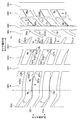
- FIG. 1 is a meridional sectional view of a tread portion of a pneumatic tire according to an embodiment of the present invention.
- FIG. 2 is a plan view of the tread portion of the pneumatic tire according to the embodiment of the present invention.
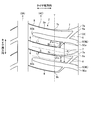
- FIG. 3 is a partially enlarged plan view of the tread portion of the pneumatic tire according to the embodiment of the present invention.
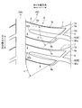
- FIG. 4 is a partially enlarged plan view of the tread portion of the pneumatic tire according to the embodiment of the present invention.
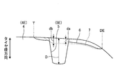
- FIG. 5 is a partially enlarged cross-sectional view of the tread portion of the pneumatic tire according to the embodiment of the present invention.
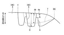
- FIG. 6 is a partially enlarged cross-sectional view of the tread portion of the pneumatic tire according to the embodiment of the present invention.
- FIG. 7 is a partially enlarged plan view of the tread portion of the pneumatic tire according to the embodiment of the present invention.
- FIG. 8 is a chart showing the results of the performance test of the pneumatic tire according to the example of the present invention.
- FIG. 1 is a meridional sectional view of a tread portion of a pneumatic tire according to this embodiment.
- FIG. 2 is a plan view of the tread portion of the pneumatic tire according to the present embodiment.
- the tire circumferential direction refers to a circumferential direction having a rotation axis (not shown) of the pneumatic tire 1 as a central axis.
- the tire width direction means a direction parallel to the rotation axis
- the inner side in the tire width direction means the side toward the tire equator plane (tire equator line) CL in the tire width direction
- the outer side in the tire width direction means the tire width direction. Is the side away from the tire equatorial plane CL.
- the tire radial direction refers to a direction orthogonal to the rotation axis
- the inner side in the tire radial direction refers to the side toward the rotation axis in the tire radial direction
- the outer side in the tire radial direction refers to the side away from the rotation axis in the tire radial direction.
- the tire equatorial plane CL is a plane that is orthogonal to the rotational axis and passes through the center of the tire width of the pneumatic tire 1.
- the tire equator line is a line along the tire circumferential direction of the pneumatic tire 1 on the tire equator plane CL. In the present embodiment, the same sign “CL” as that of the tire equator plane is attached to the tire equator line.
- the pneumatic tire 1 of the present embodiment has a tread portion 2 as shown in FIGS. 1 and 2.
- the tread portion 2 is made of a rubber material, exposed at the outermost side in the tire radial direction of the pneumatic tire 1, and the surface thereof becomes the contour of the pneumatic tire 1 as a tread surface 2 a.
- the tread portion 2 is provided with a plurality of (four in this embodiment) circumferential grooves 3 extending along the tire circumferential direction in the tread surface 2a.
- these circumferential grooves 3 one (right side in FIGS. 1 and 2) has one circumferential groove 3 as a first circumferential groove 3 ⁇ / b> A, and the other one from the first circumferential groove 3 ⁇ / b> A (leftward in FIGS. 1 and 2). ),
- the second circumferential groove 3B, the third circumferential groove 3C, and the fourth circumferential groove 3D The first circumferential groove 3A and the second circumferential groove 3B are arranged on the outer side in the tire width direction on one side (right side in FIGS.
- the circumferential groove 3 is, for example, one having a groove width of 5 mm or more and 15 mm or less and a groove depth (a dimension from the opening position of the tread surface 2a to the groove bottom) of 5 mm or more and 15 mm or less.
- the tread portion 2 includes a plurality of land portions 4 (five in the present embodiment) divided in the tire width direction by circumferential grooves 3 on the tread surface 2a.
- the land portion 4 between the second circumferential groove 3B and the third circumferential groove 3C and on the tire equatorial plane CL is defined as a center land portion 4A.
- the land portion 4 between the first circumferential groove 3A and the second circumferential groove 3B and adjacent to the outer side in the tire width direction of the center land portion 4A is referred to as a first intermediate land portion 4B.
- the land portion 4 between the third circumferential groove 3C and the fourth circumferential groove 3D and adjacent to the other side in the tire width direction of the center land portion 4A is referred to as a second intermediate land portion 4C.
- first shoulder land portion 4D the land portion 4 on the outer side in the tire width direction of the fourth circumferential groove 3D and adjacent to the outer side in the tire width direction of the second intermediate land portion 4C and the outermost land portion 4 in the tire width direction.
- second shoulder land portion 4E the land portion 4 on the outer side in the tire width direction of the first circumferential groove 3A, adjacent to the outer side in the tire width direction of the first intermediate land portion 4B, and the outermost land portion 4 in the tire width direction.
- the tread portion 2 has a ground contact end T in the first shoulder land portion 4D and the second shoulder land portion 4E which are the outermost land portions 4 in the tire width direction. Moreover, the tread part 2 makes the design end DE the tire width direction outer side end of the 1st shoulder land part 4D which is the outermost land part 4 in the tire width direction, and the second shoulder land part 4E.
- the ground contact end T means both outermost ends in the tire width direction of the ground contact region, and in FIG. 2, the ground contact end T is shown continuously in the tire circumferential direction.
- the ground contact area is a flat surface in which the tread surface 2a of the tread portion 2 of the pneumatic tire 1 is dried when the pneumatic tire 1 is assembled on a regular rim and filled with a regular internal pressure and 70% of the regular load is applied. This is an area where it touches the ground.
- the regular rim is “standard rim” defined by JATMA, “Design Rim” defined by TRA, or “Measuring Rim” defined by ETRTO.
- the normal internal pressure is “maximum air pressure” defined by JATMA, the maximum value described in “TIRE LOAD LIMITS AT VARIOUS COLD INFLATION PRESSURES” defined by TRA, or “INFLATION PRESSURES” defined by ETRTO.
- the normal load is “maximum load capacity” defined by JATMA, the maximum value described in “TIRE LOAD LIMITS AT VARIOUS COLD INFLATION PRESSURES” defined by TRA, or “LOAD CAPACITY” defined by ETRTO.
- the design end DE refers to the outermost end in the tire width direction of the tread portion 2 on the outer side in the tire width direction of the ground contact end T, and is the outermost end in the tire width direction in which a groove is formed in the tread portion 2. In FIG. 2, the design end DE is shown continuously in the tire circumferential direction. That is, in the tread portion 2, on the dry flat road surface, the area closer to the design end DE than the ground contact end T is an area that does not contact the normal road surface
- the pneumatic tire 1 of the present embodiment is characterized by the configuration of the second shoulder land portion 4E, and the second shoulder land portion 4E will be mainly described below.
- 3 and 4 are partially enlarged plan views of the tread portion of the pneumatic tire according to the present embodiment.
- 5 and 6 are partially enlarged cross-sectional views of the tread portion of the pneumatic tire according to the present embodiment.
- 3 to 6 are enlarged views of the second shoulder land portion 4E.
- the pneumatic tire 1 of the present embodiment includes a lug groove 5, a crossing narrow groove 6, a branching narrow groove 7, and a widthwise narrow groove 8 in the second shoulder land portion 4 ⁇ / b> E. And are formed.
- the lug groove 5 of the second shoulder land portion 4E is the second shoulder land portion lug groove 5E in the present embodiment.
- the second shoulder land portion lug groove 5E is provided so as to intersect the tire circumferential direction so as to intersect the ground contact end T.
- the second shoulder land portion lug groove 5E has one end 5Ea on the outer side in the tire width direction and opens to the design end DE, and the other end 5Eb terminates in the second shoulder land portion 4E and becomes the first circumferential groove 3A. Do not communicate.
- a plurality of the second shoulder land lug grooves 5E are provided at intervals in the tire circumferential direction.
- Each second shoulder land lug groove 5E extends substantially in parallel and is provided without intersecting each other.
- the other end 5Eb of the second shoulder land lug groove 5E may communicate with the first circumferential groove 3A.
- the intersecting narrow grooves 6 are provided so as to intersect with the second shoulder land portion lug grooves 5E at positions outside the ground contact end T in the tire width direction.
- the intersecting narrow groove 6 is open at one end 6a on the outer side in the tire width direction and reaching the design end DE, and the other end 6b terminates in the second shoulder land portion 4E and does not communicate with the first circumferential groove 3A.
- the crossing narrow grooves 6 are preferably provided such that the other end 6b terminates on the outer side in the tire width direction from the ground contact end T, and all of them are provided on the outer side in the tire width direction from the ground contact end T.
- the other end 6b may be provided so as to terminate on the inner side in the tire width direction from the ground contact end T.
- the branched narrow grooves 7 are branched from the intersecting narrow grooves 6 and are disposed between the second shoulder land lug grooves 5E.
- the branched narrow groove 7 branches from one end 6a of the intersecting narrow groove 6 so that one end 7a is on the outer side in the tire width direction and reaches the design end DE, and the other end 7b terminates in the second shoulder land portion 4E. Therefore, it does not communicate with the first circumferential groove 3A.
- the branched narrow groove 7 has the other end 7b terminated at the outer side in the tire width direction from the ground contact end T, and is all provided at the outer side in the tire width direction from the ground contact end T.
- the other end 7b may be provided so as to terminate on the inner side in the tire width direction with respect to the ground contact end T.
- the width direction narrow groove 8 is provided from the first circumferential groove 3A to the other end 6b that terminates in the second shoulder land portion 4E in the intersecting narrow groove 6. Further, the width direction narrow groove 8 is provided from the first circumferential groove 3A to the other end 7b that terminates in the second shoulder land portion 4E in the branch narrow groove 7. That is, the intersecting narrow groove 6 and the branching narrow groove 7 are communicated with the first circumferential groove 3 ⁇ / b> A through the width-direction narrow groove 8 at the ends (the other ends 6 b, 7 b) in the tire width direction.
- the lug groove 5 is, for example, one having a groove width of 1.5 mm or more, a groove width of the circumferential groove 3 or less, and a groove depth of the circumferential groove 3 or less.
- the intersecting narrow grooves 6 and the branched narrow grooves 7 are, for example, those having a groove width of 0.4 mm or more and 1.5 mm or less and a depth of the circumferential groove 3 or less.
- the width direction narrow groove 8 is, for example, a groove width of 0.4 mm or more and 1.5 mm or less, the intersecting narrow groove 6 and the branching narrow groove 7 or less, and the groove depth of the circumferential groove 3 or the lug groove 5 or less. Means things. When the groove depth changes in the lug groove 5, the crossing narrow groove 6, the branching narrow groove 7, and the width direction narrow groove 8, the deepest groove depth is set to the above range.
- the groove width and groove depth are communicated with each other in the width direction narrow groove 8, the intersecting narrow groove 6, and the branching narrow groove 7, but this communicating portion is defined by a change in the groove width. Further, the width direction narrow groove 8, the intersecting narrow groove 6, and the branching narrow groove 7 may have the same groove depth at the communicating portion, but the width direction narrow groove 8 and the intersecting narrow groove 6 and the branching narrow groove 7 may be the same. The groove depth may be deep.
- the pneumatic tire 1 of the present embodiment has the tire width direction outermost side by the circumferential groove 3 (first circumferential groove 3A) extending along the tire circumferential direction on the tread surface 2a of the tread portion 2.
- a second shoulder land portion 4E (land portion 4) is formed at the second shoulder land portion 4E, and a ground contact end T exists on the second shoulder land portion 4E.
- a plurality of second shoulder land portion lug grooves 5E (lug grooves 5) provided in the direction and the second shoulder land portion lug grooves 5E are provided so as to intersect at the outer side in the tire width direction from the ground contact end T. Intersecting narrow grooves 6.
- the crossing narrow groove 6 that intersects the second shoulder land portion lug groove 5 ⁇ / b> E is provided on the outer side in the tire width direction from the ground contact end T, Since the intersection of the two-shoulder land lug groove 5E and the intersecting narrow groove 6 exists in the ground contact area that enters into the snow and extends substantially outward in the tire width direction, braking on the road surface is improved. The performance can be improved. In addition, since the intersection between the second shoulder land lug groove 5E and the intersecting narrow groove 6 does not exist outside the ground contact area on the dry road surface, it does not affect the traveling on the dry road surface and the wet road surface.
- the second shoulder land portion 4E branches from the intersecting narrow grooves 6 on the outer side in the tire width direction than the ground contact end T and extends inward in the tire width direction.
- a branched narrow groove 7 is provided between each second shoulder land lug groove 5E.
- the branch portion of the crossing narrow groove 6 and the branching narrow groove 7 enters the ground contact region that enters into the snow and substantially spreads outward in the tire width direction. Therefore, the traction on the road surface on snow is improved, and the braking performance can be further improved.
- the branching portion between the intersecting narrow groove 6 and the branching narrow groove 7 does not exist outside the ground contact area on the dry road surface, it does not affect the traveling on the dry road surface and the wet road surface.
- the cross narrow groove 6 and the branch narrow groove 7 end at the inner end 6b, 7b in the tire width direction at the second shoulder land 4E.
- the crossing narrow groove 6 and the branching narrow groove 7 are provided to terminate at the second shoulder land portion 4 ⁇ / b> E, thereby suppressing a decrease in rigidity of the second shoulder land portion 4 ⁇ / b> E.
- the influence on the braking performance on the dry road surface can be suppressed.
- the intersecting narrow grooves 6 are formed in the second shoulder land where the end portion (the other end 6 b) on the inner side in the tire width direction is adjacent in the tire circumferential direction. It is preferable that it is arranged near the second shoulder land lug groove 5E where it intersects rather than the middle S of the part lug groove 5E.
- the branch narrow groove 7 is an intersecting narrow groove in which the end (the other end 7b) on the inner side in the tire width direction branches from the middle S of each second shoulder land lug groove 5E adjacent in the tire circumferential direction. It is preferable that the second shoulder land portion lug groove 5E intersecting with 6 is disposed.
- each second shoulder land lug groove 5E adjacent in the tire circumferential direction is the center between each second shoulder land lug groove 5E adjacent in the tire circumferential direction, and each second shoulder land lug It is indicated by a center line parallel to the auxiliary line L passing through the nearest groove edge of the lug groove 5E.
- the other shoulders 6 b and 7 b of the crossing narrow groove 6 and the branching narrow groove 7 have a second shoulder land lug groove rather than an intermediate S between adjacent second shoulder land lug grooves 5 E. Since it is arranged closer to 5E, even if it has the crossing narrow groove 6 and the branching narrow groove 7, the rigidity reduction of the second shoulder land portion 4E between the adjacent second shoulder land portion lug grooves 5E is suppressed. And the influence on the braking performance on the dry road surface can be suppressed.
- the distance in the tire circumferential direction (between the auxiliary lines L1 and L2) between the second shoulder land lug grooves 5E adjacent in the tire circumferential direction is defined as ⁇ .
- the auxiliary line L1 is a tangent line that is in contact with the innermost side of the opening edge of the second shoulder land lug groove 5E on the inner width direction end (other end 6b) side of the intersecting narrow groove 6.
- the auxiliary line L2 is an opening edge of the second shoulder land portion lug groove 5E intersecting with the intersecting narrow groove 6 at which the branch narrow groove 7 branches on the end (the other end 7b) side in the tire width direction of the branch narrow groove 7. It is a tangent line that touches the innermost side.
- the auxiliary lines L1 and L2 are parallel to each other. Further, the intermediate S described above is indicated by a straight line at the center of the auxiliary lines L1 and L2.
- the crossing narrow groove 6 and the branching narrow groove 7 are provided in order to divide the adjacent second shoulder land lug groove 5E into three by the crossing narrow groove 6 and the branching narrow groove 7. Even if it does, the rigidity fall of the 2nd shoulder land part 4E between each 2nd shoulder land part lug groove 5E can be suppressed, and the influence on the braking performance on a dry road surface can be suppressed.
- the angle ⁇ formed by the intersecting narrow groove 6 and the branched narrow groove 7 branched from the intersecting narrow groove 6 is in the range of ⁇ ⁇ 80 °. It is preferable to satisfy.
- the angle ⁇ draws a straight line connecting the branching point of the branching narrow groove 7 from the crossing narrow groove 6 and the tip 6 b of the crossing narrow groove 6 in the plan view of the tread portion 2.
- a straight line connecting the branching point of the branching narrow groove 7 and the tip 7b of the branching narrow groove 7 from 6 is drawn to obtain an angle formed by each straight line.
- the crossing narrow groove 6 and the branching narrow groove 7 become thick grooves that are connected to each other at the design end DE of the tread portion 2.
- the angle ⁇ is 80 ° or more
- the opening angle of the branch portion is too large and approaches the tire circumferential direction, so that the contribution to the traction on the snow road surface is low and the effect of improving the braking performance is low.
- the angle ⁇ is in the range of 40 ° to 60 °.
- the crossing narrow groove 6 and the second shoulder land portion lug groove 5E intersecting with the crossing narrow groove 6 are on the inner side in the tire width direction.
- the formed angle ⁇ preferably satisfies the range of 10 ° ⁇ ⁇ 90 °.
- the angle ⁇ connects the intersection of the cross narrow groove 6 to the second shoulder land lug groove 5E and the tip 5Eb of the second shoulder land lug groove 5E.
- a straight line is drawn, and a straight line connecting the intersection of the intersecting narrow groove 6 to the second shoulder land lug groove 5E and the tip 6b of the intersecting narrow groove 6 is drawn to obtain an angle formed by each straight line.
- the angle ⁇ is 10 ° or less, an acute angle portion is generated at the crossing portion of the crossing narrow groove 6 to the second shoulder land lug groove 5E, which may cause a failure such as a baldness at the crossing portion.
- the angle ⁇ is preferably in the range of 10 ° ⁇ ⁇ 90 °.
- the angle ⁇ is more preferably in the range of 40 ° ⁇ ⁇ 60 °.
- the crossing narrow grooves 6 and the branching narrow grooves 7 are preferably formed so that the groove width becomes narrower toward the inner side in the tire width direction.
- each second shoulder land portion is provided even if the crossing narrow groove 6 and the branching narrow groove 7 are provided.
- the rigidity reduction of the second shoulder land portion 4E between the lug grooves 5E can be suppressed, and the influence on the braking performance on the dry road surface can be suppressed.
- At least one of the intersecting narrow groove 6 and the branching narrow groove 7 has an end portion (the other end 6b, 7b) on the inner side in the tire width direction through the narrow width groove 8. It is preferable to communicate with the first circumferential groove 3A.
- this pneumatic tire 1 by providing the width direction narrow groove 8, from the end in the tire width direction (the other end 6b, 7b) of the intersecting narrow groove 6 and the branching narrow groove 7, on the inner side in the tire width direction, Since the flexibility of the second shoulder land portion 4E is improved, the braking performance on the road surface on snow can be improved. Moreover, according to the pneumatic tire 1, by providing the width direction narrow groove 8, the braking performance on the road surface on snow can be improved by the edge effect, and the braking performance on the wet road surface can be improved by improving drainage. it can.
- the groove depth da of the intersecting narrow groove 6 and the groove depth D of the second shoulder land portion lug groove 5E satisfy the range of da ⁇ 0.5D.
- the branch narrow groove 7 and the second shoulder land lug groove 5E adjacent to the branch narrow groove 7 in the tire circumferential direction are branched. It is preferable that the groove depth db of the narrow groove 7 and the groove depth D of the second shoulder land portion lug groove 5E satisfy the range of db ⁇ 0.5D.
- the crossing narrow groove 6 and the branching narrow groove 7 shown in FIG. 5 extend at substantially the same groove depth.
- the crossing narrow groove 6 shown in FIG. 6 has a shallow groove depth by raising the groove bottom at the crossing with the second shoulder land lug groove 5E.
- the groove depth D of the second shoulder land lug groove 5 ⁇ / b> E is the deepest groove depth at the intersection with the intersecting narrow groove 6.
- the groove depth da of the intersecting narrow groove 6 is the deepest groove depth at the opening to the second shoulder land lug groove 5E at the intersection with the second shoulder land lug groove 5E.
- the groove depth db of the branch narrow groove 7 is set to the deepest groove depth of the branch thin groove 7 alone except for the branch portion from the intersecting narrow groove 6.
- the groove depths da and db of the crossing narrow groove 6 and the branching thin groove 7 exceed the ranges of da ⁇ 0.5D and db ⁇ 0.5D, the groove depth is too deep.
- the rigidity of the second shoulder land portion 4E between the respective second shoulder land portion lug grooves 5E is lowered, and the braking performance on the dry road surface tends to be lowered, or failure such as baldness occurs. There is a risk of doing so. Therefore, it is preferable that the groove depths da and db of the intersecting narrow grooves 6 and the branched narrow grooves 7 are in a range of da ⁇ 0.5D and db ⁇ 0.5D. In terms of numerical values, it is preferable that the depths da and db of the intersecting narrow grooves 6 and the branched narrow grooves 7 are 2 mm or less in the above range.
- FIG. 7 is a partially enlarged plan view of the tread portion of the pneumatic tire according to the present embodiment.
- FIG. 7 is an enlarged view mainly showing the first intermediate land portion 4B.
- a first intermediate land portion 4B is formed between the first circumferential groove 3A and the second circumferential groove 3B.
- the first circumferential groove 3A has a groove width that does not change in the tire circumferential direction, and is formed linearly in the tire circumferential direction.
- the wedge part 9 is provided in the second circumferential groove 3B.
- the wedge portion 9 is provided at each opening edge of the second circumferential groove 3B on the first intermediate land portion 4B side and the center land portion 4A side, and is inclined in the tire circumferential direction to open the second circumferential groove 3B. While increasing or decreasing the number of portions, a plurality of portions are continuously provided in the tire circumferential direction.
- the plurality of wedge portions 9 have the same inclination direction at the opening edge on the first intermediate land portion 4B side, and the inclination direction is also the same at the opening edge on the center land portion 4A side.
- the wedge portion 9 is provided opposite to the opening edge on the first intermediate land portion 4B side and the opening edge on the center land portion 4A side in the tire width direction, and the inclination directions are provided in opposite directions. Yes. Therefore, in the second circumferential groove 3B, the wedge portion 9 narrows the opening width (groove width) of the second circumferential groove 3B along the tire circumferential direction which is the extending direction of the second circumferential groove 3B. It is provided so that it can be spread out alternately.
- the wedge portion 9 is formed by chamfering the opening edge of the second circumferential groove 3B with a triangular surface, and grooves other than the opening edge of the second circumferential groove 3B.
- the width is configured not to change.
- the wedge portion 9 may be formed so that the groove width of the second circumferential groove 3B extends from the groove bottom to the opening edge and the groove width increases or decreases, although not explicitly shown in the drawing.
- this wedge part 9 should just be provided in the opening edge by the side of the at least 1st intermediate land part 4B of the 2nd circumferential groove
- the second circumferential groove 3B provided with the wedge portion 9 is disposed on the side closer to the tire equatorial plane CL with respect to the first circumferential groove 3A.
- the first intermediate land portion 4B is formed with a lug groove 5, a circumferential narrow groove 10, and a width narrow groove 8.
- the lug groove 5 of the first intermediate land portion 4B is provided so as to intersect with the tire circumferential direction, and in the present embodiment, the lug groove 5B is the first intermediate land portion lug groove 5B.
- the first intermediate land portion lug groove 5B has one end 5Ba communicating with the first circumferential groove 3A and the other end 5Bb communicating with the second circumferential groove 3B.
- a plurality of the first intermediate land lug grooves 5B are provided at intervals in the tire circumferential direction.
- the first intermediate land lug grooves 5B extend substantially in parallel and are provided without intersecting each other. Each first intermediate land portion lug groove 5B divides the first intermediate land portion 4B into a plurality of block land portions arranged in the tire circumferential direction.
- Such a first intermediate land lug groove 5B is preferably disposed between each wedge portion 9 in each wedge portion 9 that increases or decreases as shown in FIGS. Although not clearly shown, it may not be arranged for each wedge part 9 but may be arranged in the middle of the inclination of the wedge part 9.
- the circumferential narrow groove 10 is provided to extend along each tire circumferential direction through the first intermediate land portion lug groove 5B adjacent in the tire circumferential direction.
- the circumferential narrow groove 10 is connected to each first intermediate land lug groove 5B between the adjacent first intermediate land lug grooves 5B at both ends in the tire circumferential direction.
- the block land portion formed between the grooves 5B is equally divided into two in the tire width direction.
- the circumferential narrow groove 10 is provided such that the groove width between the adjacent first intermediate land lug grooves 5B is increased or decreased in the tire circumferential direction.
- the circumferential narrow groove 10 is formed such that the groove wall extends from the groove bottom to the opening edge and the groove width increases or decreases.
- the circumferential narrow groove 10 extends from one first intermediate land lug groove 5B to the other first intermediate land lug groove 5B in the block land portion between the adjacent first intermediate land lug grooves 5B.
- the groove width is uniformly increased or decreased in one direction in the tire circumferential direction from one end to the other end, and the increase / decrease is not reversed in the middle.
- the 1st intermediate land part lug groove 5B is arrange
- channel 3B side of the block land part formed between each 1st middle land part lug groove 5B is divided
- the circumferential narrow groove 10 is formed so that the groove depth becomes shallower as the groove width decreases when the groove width uniformly increases or decreases in one direction in the tire circumferential direction.
- the wedge part 9 of the 2nd circumferential groove 3B is formed by chamfering, the said wedge part 9 is provided in the position shallower than the groove depth of the circumferential direction fine groove 10, and the circumferential direction fine groove
- the tread surface 2a is provided more than the bottom of the groove 10.
- the width direction narrow groove 8 of the first intermediate land portion 4B is for equally dividing the block land portion between the adjacent first intermediate land portion lug grooves 5B into two in the tire circumferential direction. As shown in FIGS. 2 and 7, the width direction narrow groove 8 intersects the circumferential direction narrow groove 10 at the center in the tire circumferential direction of each adjacent first intermediate land portion lug groove 5B, and one end 8a is the first. It communicates with the circumferential groove 3A, and the other end 8b communicates with the second circumferential groove 3B. Thereby, the width direction narrow groove 8 divides the block land part between each adjacent 1st intermediate land part lug groove 5B into a tire circumferential direction.
- the width direction narrow groove 8 intersects the circumferential direction narrow groove 10, one end 8a communicates with the adjacent first intermediate land lug groove 5B, and the other end 8b is adjacent.
- the block land portion between the adjacent first intermediate land portion lug grooves 5B may be divided into two in the tire circumferential direction by communicating with the other first intermediate land portion lug groove 5B.
- a center land portion 4A is formed between the second circumferential groove 3B and the third circumferential groove 3C and on the tire equatorial plane CL.
- the third circumferential groove 3C has a groove width that does not change in the tire circumferential direction, and is formed linearly in the tire circumferential direction.
- the center land portion 4A has a lug groove 5 and a width direction narrow groove 8 formed therein.
- the lug grooves 5 of the center land portion 4A are provided so as to intersect with the tire circumferential direction.
- the center land portion first lug groove 5A has one end 5Aa communicating with the second circumferential groove 3B and the other end 5Ab terminating in the center land portion 4A.
- a plurality of the center land portion first lug grooves 5A are provided at intervals in the tire circumferential direction.
- each center land part 1st lug groove 5A is extended substantially parallel, and is provided without mutually crossing.
- the center land portion first lug groove 5A has one end 5Aa opposed to the other end 5Bb of the first intermediate land portion lug groove 5B in the second circumferential groove 3B, and the first intermediate land portion lug groove 5B in the plan view. And is provided so as to penetrate the second circumferential groove 3B.
- the center land portion second lug groove 5A ' has one end 5A'a communicating with the third circumferential groove 3C and the other end 5A'b terminating in the center land portion 4A.
- a plurality of the center land portion second lug grooves 5A ' are provided at intervals in the tire circumferential direction.
- Each center land portion second lug groove 5A ' extends substantially in parallel and is provided without intersecting each other.
- the narrow land 8 in the center land portion 4A has one end 8a communicating with the third circumferential groove 3C and the other end 8b terminating in the center land portion 4A.
- the width direction narrow groove 8 is provided between each center land portion second lug groove 5A ′ adjacent in the tire circumferential direction, and extends substantially parallel to the center land portion second lug groove 5A ′. It is provided without intersecting the center land portion second lug groove 5A ′ and the center land portion first lug groove 5A.
- the width direction narrow groove 8 terminates at the position where the other end 8b does not intersect the tire equator plane CL or the tire equator plane CL.
- a second intermediate land portion 4C is formed between the third circumferential groove 3C and the fourth circumferential groove 3D.
- the fourth circumferential groove 3D has a groove width that does not change in the tire circumferential direction, and is formed linearly in the tire circumferential direction.
- the fourth circumferential groove 3D is the outermost circumferential groove 3 across the tire equatorial plane CL together with the first circumferential groove 3A, and is formed with substantially the same groove width.
- the fourth circumferential groove 3D and the first circumferential groove 3A are formed to have a larger groove width than the second circumferential groove 3B and the third circumferential groove 3C on the inner side in the tire width direction. Further, since the wedge portion 9 is formed in the second circumferential groove 3B, the groove width is formed smaller than that in the third circumferential groove 3C.
- the lug groove 5 and the width direction narrow groove 8 are formed in the second intermediate land portion 4C.
- the lug grooves 5 of the second intermediate land portion 4C are provided so as to intersect the tire circumferential direction, and the second intermediate land portion main lug groove (second intermediate land portion lug groove) 5C and the second intermediate land portion sub-lug.
- the second intermediate land portion main lug groove 5C has one end 5Ca communicating with the third circumferential groove 3C and the other end 5Cb communicating with the fourth circumferential groove 3D.
- a plurality of the second intermediate land portion main lug grooves 5C are provided at intervals in the tire circumferential direction.
- Each of the second intermediate land main lug grooves 5C extends substantially in parallel and is provided without intersecting each other.
- Each second intermediate land portion main lug groove 5C divides the second intermediate land portion 4C into a plurality of block land portions arranged in the tire circumferential direction.
- one end 5Ca of the third circumferential groove 3C is opposed to one end 5A'a of the center land portion second lug groove 5A '.
- the lug groove 5A ′ is integrated with the third circumferential groove 3C.
- the second intermediate land portion sub-lag groove 5C ' has one end 5C'a communicating with the fourth circumferential groove 3D and the other end 5C'b terminating in the second intermediate land portion 4C.
- One second intermediate land sub-lug groove 5C ′ is provided between each second intermediate land main lug groove 5C adjacent in the tire circumferential direction, and substantially parallel to the second intermediate land main lug groove 5C. And provided without intersecting the second intermediate land main lug groove 5C.
- the widthwise narrow groove 8 of the second intermediate land portion 4C has one end 8a communicating with the end of the other end 5C′b of the second intermediate land portion sub-lag groove 5C ′ and the other end 8b connected to the third circumferential groove 3C. Communicate.
- the width direction narrow groove 8 has the other end 8b facing the one end 8a of the width direction narrow groove 8 of the center land portion 4A in the third circumferential direction groove 3C. It is provided through the direction groove 3C.
- the first shoulder land portion 4D is formed on the outer side in the tire width direction of the fourth circumferential groove 3D.
- the first shoulder land portion 4D is formed with a lug groove 5, a shoulder land portion narrow groove 11, and a width direction narrow groove 8.
- the lug grooves 5 of the first shoulder land portion 4D are provided so as to intersect the tire circumferential direction, and are referred to as a first shoulder land portion main lug groove 5D and a first shoulder land portion sub lug groove 5D '.
- the first shoulder land portion main lug groove 5D has one end 5Da on the outer side in the tire width direction and opens to the design end DE, and the other end 5Db communicates with the fourth circumferential groove 3D.
- a plurality of the first shoulder land portion main lug grooves 5D are provided at intervals in the tire circumferential direction.
- each 1st shoulder land part main lug groove 5D is extended substantially in parallel, and is provided without mutually crossing.
- Each first shoulder land portion main lug groove 5D divides the first shoulder land portion 4D into a plurality of block land portions arranged in the tire circumferential direction.
- the other end 5Db of the fourth circumferential groove 3D is opposed to one end 5C′a of the second intermediate land portion sub lug groove 5C ′.
- the fourth circumferential groove 3D is provided so as to be integrated with the land portion sub-lag groove 5C ′.
- first shoulder land portion main lug groove 5D, the second intermediate land portion sub lug groove 5C ′, the width direction narrow groove 8 of the second intermediate land portion 4C, and the width direction narrow groove 8 of the center land portion 4A are integrally provided through the design end DE through the fourth circumferential groove 3D and the third circumferential groove 3C.
- the first shoulder land portion sub-lag groove 5D ' has one end 5D'a communicating with the fourth circumferential groove 3D and the other end 5D'b terminating in the first shoulder land portion 4D.
- One first shoulder land portion main lug groove 5D ′ is provided between the first shoulder land portion main lug grooves 5D adjacent in the tire circumferential direction, and substantially parallel to the first shoulder land portion main lug groove 5D.
- the first shoulder land portion main lug groove 5D is provided without intersecting with the first shoulder land portion main lug groove 5D.
- the first shoulder land portion sub-lug groove 5D ′ has one end 5D′a facing the other end 5Cb of the second intermediate land portion main lug groove 5C in the fourth circumferential groove 3D.
- the land portion main lug groove 5C is integrated with the fourth circumferential groove 3D.
- the shoulder land portion narrow groove 11 has one end 11a on the outer side in the tire width direction and opens to the design end DE, and the other end 11b terminates in the first shoulder land portion 4D and does not communicate with the fourth circumferential groove 3D.
- the shoulder land portion narrow groove 11 has the other end 11b that terminates on the outer side in the tire width direction from the ground contact end T, and is all provided on the outer side in the tire width direction from the ground contact end T.
- the other end 11b may be provided to terminate from the ground contact end T on the inner side in the tire width direction.
- one shoulder land narrow groove 11 is provided between each first shoulder land main lug groove 5D adjacent in the tire circumferential direction, and extends substantially parallel to the first shoulder land main lug groove 5D.
- the first shoulder land portion main lug groove 5D is provided without intersecting.
- the widthwise narrow groove 8 of the first shoulder land portion 4D has one end 8a communicating with the end of the other end 5D′b of the first shoulder land portion sub-lag groove 5D ′ and the other end 8b of the shoulder land portion narrow groove 11. It communicates with the end of the other end 11b. That is, the shoulder land portion narrow groove 11, the width direction narrow groove 8 of the first shoulder land portion 4D, the first shoulder land portion sub lug groove 5D ′, the second intermediate land portion main lug groove 5C, and the center land portion.
- the second lug groove 5A ′ is provided integrally through the fourth circumferential groove 3D and the third circumferential groove 3C.
- the lug groove 5 is, for example, one having a groove width of 1.5 mm or more, a groove width of the circumferential groove 3 or less, and a groove depth of the circumferential groove 3 or less.
- the circumferential narrow groove 10 and the shoulder land narrow groove 11 are, for example, 4.0 mm or less (preferably having a groove width of 1.0 mm or more and 4.0 mm or less and a depth of the circumferential groove 3 or less.
- the width direction narrow groove 8 is, for example, a groove width of 0.4 mm or more and 1.5 mm or less and the circumferential direction narrow groove 10 and the shoulder land portion narrow groove 11 or less. It is said to have a groove depth of not more than 5. When the groove depth changes in the circumferential narrow groove 10 and the shoulder land narrow groove 11, the deepest groove depth is within the above range.
- the width direction narrow groove 8 communicates with the circumferential direction narrow groove 10 and the shoulder land portion narrow groove 11, and this communication portion is defined by a change in the groove width.
- the width direction narrow groove 8, the circumferential direction narrow groove 10, and the shoulder land portion narrow groove 11 may have the same groove depth in the communicating portion, but the circumferential direction narrow groove 10 and the width direction narrow groove 8
- the groove depth of the shoulder land portion narrow groove 11 may be formed deep.
- the pneumatic tire 1 of the present embodiment includes the first circumferential groove 3A and the second circumferential groove 3B provided on the tread surface 2a of the tread portion 2 so as to extend along the tire circumferential direction.
- the first intermediate land portion 4B formed between the circumferential grooves 3A and 3B and the opening edge on at least the first intermediate land portion 4B side in the second circumferential groove 3B
- a plurality of wedge portions 9 provided continuously in the tire circumferential direction, and a plurality of first intermediate land portions 4B in the tire circumferential direction are provided in the tire circumferential direction by connecting each end to the circumferential grooves 3A and 3B.
- Each block land is divided into two in the tire width direction, and each adjacent first intermediate land Comprising the groove width between the grayed groove 5B is a circumferential narrow groove 10 extending along the tire circumferential direction by increasing or decreasing, the.
- the braking performance on the road surface on snow is improved by the edge effect obtained by the wedge portion 9 in the first intermediate land portion 4B formed by the first circumferential groove 3A and the second circumferential groove 3B. Can be improved.
- the first intermediate land portion 4B is divided into a plurality of block land portions arranged in the tire circumferential direction by the first intermediate land portion lug groove 5B, thereby improving the edge effect and improving the braking performance on the road surface on snow and draining.
- the braking performance on wet road surfaces can be improved.
- the edge effect obtained by the increase or decrease in the groove width causes the snow on the snow.
- the braking performance on the road surface can be improved and the drainage can be improved to improve the braking performance on the wet road surface.
- the wedge part 9 is provided in both opening edges in the 2nd circumferential groove 3B, and can improve the braking performance on a snowy road surface more by the edge effect.
- the circumferential narrow groove 10 divides the block land portion between the first intermediate land lug grooves 5B equally into two in the tire width direction, so that the area of the land tread surface 2a becomes uniform. Since an extreme decrease in rigidity of the land portion can be suppressed, a decrease in braking performance on a dry road surface can be suppressed.
- the first intermediate land portion lug groove 5B is disposed for each wedge portion 9 of the second circumferential groove 3B, and the circumferential narrow groove 10 is provided for each first intermediate land portion. It is preferable that the groove width be increased or decreased along the inclination of the wedge portion 9 between the lug grooves 5B.
- the shape of the land portion tread surface 2 a surrounded by the first intermediate land portion lug groove 5 ⁇ / b> B, the wedge portion 9 of the second circumferential groove 3 ⁇ / b> B, and the circumferential narrow groove 10 is formed. Since it becomes almost a parallelogram and the rigidity of the land portion can be made uniform, it is possible to suppress a decrease in braking performance on a dry road surface.
- the circumferential narrow groove 10 is provided with an increased or decreased groove width along the inclination of the wedge portion 9, so that the groove width increases or decreases uniformly in one direction in the tire circumferential direction. It is preferable that the groove depth becomes shallower as the thickness decreases. Accordingly, the pneumatic tire 1 is configured such that the high rigidity side having a small groove width and a shallow groove depth is defined as the stepping side, and the low rigidity side having the large groove width and the deep groove depth is defined as the kicking side. By designating the direction of rotation, it becomes strong to stepping on and kicking out can be made soft, and braking performance on a dry road surface can be improved. Although the designation of the rotation direction of the pneumatic tire 1 is not clearly shown in the drawing, it is indicated by, for example, an index (for example, an arrow pointing when the vehicle moves forward) provided on the tire side.
- an index for example, an arrow pointing when the vehicle moves forward
- the wedge portion 9 is preferably formed by chamfering provided at the opening edge of the second circumferential groove 3B.
- this pneumatic tire 1 by forming the wedge portion 9 by chamfering, it is possible to suppress the decrease in rigidity by suppressing the volume reduction of the land portion while obtaining the edge effect, and on the snowy road surface and the dry road surface. It is possible to achieve both braking performance.
- the width direction narrow groove 8 that divides the block land portion between the first intermediate land portion lug grooves 5B into two in the tire circumferential direction.
- the braking effect on the road surface on snow can be improved by the edge effect of the width direction narrow groove 8, and the braking performance on the wet road surface can be improved by improving the drainage performance.
- the area in the tread surface 2a of a land part becomes equal by dividing the block land part between each 1st intermediate land part lug groove 5B equally into the tire circumferential direction, and the width direction narrow groove 8 becomes equal. Since an extreme decrease in rigidity of the land portion can be suppressed, a decrease in braking performance on a dry road surface can be suppressed.
- the second circumferential groove 3B provided with the wedge portion 9 is preferably disposed on the side closer to the tire equatorial plane CL with respect to the first circumferential groove 3A. .
- the effect of improving the braking performance on the road surface on snow due to the edge effect of the wedge portion 9 can be obtained more prominently by being arranged near the tire equatorial plane CL. Therefore, by arranging the second circumferential groove 3B provided with the wedge portion 9 on the side closer to the tire equatorial plane CL, the effect of improving the braking performance on the road surface on snow can be obtained remarkably.
- the second circumferential groove 3B provided with the wedge portion 9 is disposed on the side close to the tire equatorial plane CL, and the second circumferential groove 3B on the tire equatorial plane CL side.
- One end 5Aa communicates with the groove 3B, the other end 5Ab terminates in the center land portion 4A, and a plurality of center land portion first lug grooves 5A are provided in the tire circumferential direction, and one end 5A′a at the third circumferential groove 3C.
- the other end 5A′b terminates in the center land portion 4A and has a plurality of center land portion second lug grooves 5A ′ provided in the tire circumferential direction, and the center land portion first lug groove 5A and the center
- the land second lug groove 5A 'does not communicate with each other and is arranged alternately in the tire circumferential direction. It is preferable to have.
- the center land portion first lug groove 5A and the center land portion second lug groove 5A ′ provided to terminate at the center land portion 4A provided on the tire equatorial plane CL are connected. Since the center land portion 4A is formed in a rib shape by being alternately arranged in the tire circumferential direction without passing through, by suppressing the rigidity decrease of the center land portion 4A contributing to the improvement of the braking performance on the dry road surface The braking performance on the dry road surface can be improved.
- one end 8a communicates with the third circumferential groove 3C and the other end 8b is provided with a width direction narrow groove 8 that terminates in the center land portion 4A.
- the center land portion first lug groove 5A, the center land portion second lug groove 5A ′ and the width direction narrow groove 8 do not intersect the other ends 5Ab, 5A′b and 8b on the tire equator plane CL or the tire equator plane CL.
- the third circumferential groove 3C is formed between the third circumferential groove 3C by the fourth circumferential groove 3D provided adjacent to the outer side in the tire width direction of the third circumferential groove 3C.
- the second intermediate land portion 4C, the third circumferential groove 3C and the fourth circumferential groove 3D are connected to each end in a plurality of tire circumferential directions, and a plurality of second intermediate land portions 4C are arranged in the tire circumferential direction. It is preferable to include a second middle land portion main lug groove (second middle land portion lug groove) 5C that is divided into land portions.
- the first intermediate land portion 4B and the second intermediate land portion 4C formed on both sides in the tire width direction of the center land portion 4A on the tire equatorial plane CL are each divided into block land portions.
- the extreme of the land portion sandwiching the center land portion 4A by the mutual block land portion The braking performance on the dry road surface can be ensured by suppressing the difference in rigidity.
- one end 5C'a communicates with the fourth circumferential groove 3D, and the other end 5C'b ends in the second intermediate land portion 4C.
- one end 8a communicates with the end of the other end 5C'b of the second intermediate land portion sub-lag groove 5C ', and the other end 8b communicates with the third circumferential groove 3C.
- the first shoulder land portion 4D is formed on the outer side in the tire width direction of the fourth circumferential groove 3D, and the one end 5Da penetrates the first shoulder land portion 4D and the tread surface 2a.
- the first shoulder land main lug groove 5D which is open to the outside in the tire width direction and has the other end 5Db communicating with the fourth circumferential groove 3D and provided in the tire circumferential direction, is adjacent in the tire circumferential direction.
- a first shoulder land sub-lug groove 5D provided between the land main lug grooves 5D and having one end 5D'a communicating with the fourth circumferential groove 3D and the other end 5D'b terminating in the first shoulder land portion 4D. It is preferable to include '.
- the first shoulder land portion 4D in addition to the first shoulder land portion main lug grooves 5D provided in the tire circumferential direction, the first shoulder land portion main adjacent in the tire circumferential direction.
- the first shoulder land portion sub-lug groove 5D ′ between the lug grooves 5D, the braking performance on the road surface on snow due to the mutual edge effect of the lug grooves 5D and 5D ′ and the braking performance on the wet road surface due to the drainage effect are improved. Improvements can be made.
- one end 11a penetrates the first shoulder land portion 4D and opens to the outer side in the tire width direction of the tread surface 2a, and the other end 11b terminates in the first shoulder land portion 4D.
- the narrow groove 11 and one end 8a communicate with the end of the other end 5D'b of the first shoulder land sub-lag groove 5D ', and the other end 8b communicates with the end of the other end 11b of the shoulder land narrow groove 11.
- the first circumferential groove 3A of the first circumferential groove 3A or the second circumferential groove 3B is arranged on the outer side in the tire width direction, and the first circumferential groove 3A
- a second shoulder land portion 4E formed on the outer side in the tire width direction and one end 5Ea pass through the second shoulder land portion 4E and open to the outer side in the tire width direction of the tread surface 2a, and the other end 5Eb is the second shoulder land portion 4E.
- a plurality of second shoulder land lug grooves 5E that are terminated in the tire circumferential direction and the second shoulder land lug grooves 5E that are adjacent in the tire circumferential direction are provided to intersect the tire circumferential direction. It is preferable to include at least one width-direction narrow groove 8.
- the second shoulder land portion lug grooves 5E adjacent in the tire circumferential direction are provided.
- the width direction narrow groove 8 between the braking performance on the road surface on snow by the edge effect of the second shoulder land portion lug groove 5E and the width direction narrow groove 8 and the braking performance on the wet road surface by the drainage effect are improved. Can be planned.
- the narrow groove 8 in the width direction preferably has a groove width of 0.4 mm or more and 1.5 mm or less.
- the width of the width direction narrow groove 8 is 0.4 mm or more and 1.5 mm or less.
- the center land portion first lug groove 5A of the center land portion 4A and the first intermediate land portion lug groove 5B of the first intermediate land portion 4B have one end 5Aa in the second circumferential groove 3B.
- the other end 5Bb are opposed to each other and are provided so as to penetrate the second circumferential groove 3B. Therefore, drainage is improved and the braking performance on a wet road surface can be improved by allowing the groove to penetrate the second circumferential groove 3B in the tire width direction.
- the center land portion second lug groove 5A ′ of the center land portion 4A and the second intermediate land portion main lug groove 5C of the second intermediate land portion 4C are in the third circumferential groove 3C.
- One end 5Ca and one end 5A'a are opposed to each other and are provided so as to penetrate the third circumferential groove 3C.
- the second intermediate land portion main lug groove 5C and the first shoulder land portion sub-lug groove 5D ′ of the first shoulder land portion 4D have the other end 5Cb and one end 5D′a in the fourth circumferential groove 3D.
- the fourth circumferential groove 3D is provided so as to penetrate therethrough.
- first shoulder land portion sub-lug groove 5D ', the shoulder land portion narrow groove 11, and the width direction narrow groove 8 of the first shoulder land portion 4D are integrally connected. Accordingly, the grooves penetrate through the third circumferential groove 3C and the fourth circumferential groove 3D in the tire width direction, thereby improving drainage and contributing to improvement of braking performance on wet road surfaces.
- the other end 5D′b of the first shoulder land portion sub-lag groove 5D ′ communicates with the width direction narrow groove 8, but the width direction narrow groove 8 is the first shoulder land portion 4D. Since the groove width is narrower than the partial sub lug groove 5D ′, it is substantially terminated in the first shoulder land portion 4D. Since the terminal end of the first shoulder land portion sub-lag groove 5D 'is on the inner side in the tire width direction with respect to the ground contact end T, the emission of air column resonance noise is suppressed.
- the width direction narrow groove 8 of the center land portion 4A and the width direction narrow groove 8 of the second intermediate land portion 4C have one end 8a and the other end 8b in the third circumferential groove 3C.
- the third circumferential groove 3 ⁇ / b> C is provided so as to be opposed to and integrated with each other.
- the width direction narrow groove 8 of the second intermediate land portion 4C has one end 8a communicating with the other end 5C'b of the second intermediate land portion sub-lag groove 5C '.
- the second intermediate land sub-lug groove 5C ′ and the first shoulder land main lug groove 5D of the first shoulder land part 4D have one end 5C′a and the other end 5Db in the fourth circumferential groove 3D.
- the fourth circumferential groove 3D is provided so as to penetrate therethrough. Accordingly, the grooves penetrate through the third circumferential groove 3C and the fourth circumferential groove 3D in the tire width direction, thereby improving drainage and contributing to improvement of braking performance on wet road surfaces.
- a pneumatic tire with a tire size of 205 / 55R16 was assembled to a regular rim of 16 ⁇ 6.5JJ, filled with a regular internal pressure (200 kPa), and mounted on a test vehicle (1600 cc front engine front drive vehicle). .
- the evaluation method of the braking performance on the dry road surface is that the braking distance from 100 km / h is measured on the dry road surface test course with the test vehicle. Then, based on this measurement result, index evaluation using the conventional example as a reference (100) is performed. This evaluation is preferable as the numerical value increases.
- the method for evaluating the braking performance on wet roads is to measure the braking distance from a speed of 100 km / h on a test course on a wet road with a water depth of 1 mm using the test vehicle. Then, based on this measurement result, index evaluation using the conventional example as a reference (100) is performed. This evaluation is preferable as the numerical value increases.
- the evaluation method of the braking performance on the road surface on snow measures the braking distance in ABS braking from 40 km / h on the test course on the snow compression road surface with the above test vehicle. Then, based on this measurement result, index evaluation using the conventional example as a reference (100) is performed. This evaluation is preferable as the numerical value increases.
- the pneumatic tire as the test tire has four circumferential grooves formed on the tread surface, has five land portions, and the land portion is disposed on the tire equator surface. And an intermediate land portion arranged adjacent to each other on both outer sides in the tire width direction of the center land portion, and a shoulder land portion arranged adjacent to each other on the outer side in the tire width direction of each intermediate land portion. .
- the pneumatic tire of the conventional example shown in FIG. 8 has a plurality of lug grooves arranged in the tire circumferential direction that intersect the ground contact end and communicate with the circumferential groove in one shoulder land portion, and the tire at the ground contact end between the lug grooves.
- a narrow groove that does not intersect the lug groove is provided on the outer side in the width direction.
- a plurality of lug grooves that intersect the grounding end and do not communicate with the circumferential groove in one shoulder land portion are arranged in the tire circumferential direction, and the grounding end between the lug grooves is on the outer side in the tire width direction.
- a narrow groove that does not intersect the lug groove is provided.
- a plurality of lug grooves that intersect with the ground contact edge and do not communicate with the circumferential groove in one shoulder land portion are arranged in the tire circumferential direction.
- Crossing narrow grooves that intersect the lug grooves are provided on the outer sides in the tire width direction at the ends.
Landscapes
- Engineering & Computer Science (AREA)
- Mechanical Engineering (AREA)
- Tires In General (AREA)
Abstract
Description
2 トレッド部
2a トレッド面
3A 第一周方向溝(周方向溝)
4E 第二ショルダー陸部(陸部)
5E 第二ショルダー陸部ラグ溝(ラグ溝)
6 交差細溝
7 分岐細溝
8 幅方向細溝
T 接地端
Claims (10)
- トレッド部のトレッド面に、タイヤ周方向に沿って延在する周方向溝によりタイヤ幅方向最外側に陸部が形成され、当該陸部に接地端が存在する空気入りタイヤにおいて、
前記陸部に、前記接地端に交差すると共にタイヤ周方向に複数設けられたラグ溝と、各前記ラグ溝に対して前記接地端よりもタイヤ幅方向外側にて交差して設けられた交差細溝と、を備えることを特徴とする空気入りタイヤ。 - 前記陸部に、前記接地端よりもタイヤ幅方向外側にて各前記交差細溝から分岐してタイヤ幅方向内側に向かって延在し各前記ラグ溝の間に配置される分岐細溝を備えることを特徴とする請求項1に記載の空気入りタイヤ。
- 前記交差細溝および前記分岐細溝は、タイヤ幅方向内側の端部が前記陸部内で終端することを特徴とする請求項2に記載の空気入りタイヤ。
- 前記交差細溝は、タイヤ幅方向内側の端部がタイヤ周方向で隣接する各前記ラグ溝の中間よりも自身が交差している前記ラグ溝の近くに配置されており、前記分岐細溝は、タイヤ幅方向内側の端部がタイヤ周方向で隣接する各前記ラグ溝の中間よりも自身が分岐する前記交差細溝が交差している前記ラグ溝の近くに配置されていることを特徴とする請求項2または3に記載の空気入りタイヤ。
- タイヤ周方向で隣接する各前記ラグ溝の間のタイヤ周方向の距離をαとし、
前記交差細溝のタイヤ幅方向内側の端部と自身が交差している前記ラグ溝とのタイヤ周方向の距離をβaとし、
前記分岐細溝のタイヤ幅方向内側の端部と自身が分岐する前記交差細溝が交差している前記ラグ溝とのタイヤ周方向の距離をβbとした場合、
0.1α<βa<0.5αおよび0.1α<βb<0.5αの関係を満たすことを特徴とする請求項2~4のいずれか1つに記載の空気入りタイヤ。 - 前記交差細溝と当該交差細溝から分岐する前記分岐細溝とのなす角度γは、γ<80°の範囲を満たすことを特徴とする請求項2~5のいずれか1つに記載の空気入りタイヤ。
- 前記交差細溝および前記分岐細溝は、タイヤ幅方向内側に向かって溝幅が細く形成されていることを特徴とする請求項2~6のいずれか1つに記載の空気入りタイヤ。
- 前記交差細溝と前記分岐細溝との少なくとも一方は、タイヤ幅方向内側の端部が幅方向細溝を介して前記周方向溝に連通することを特徴とする請求項2~6のいずれか1つに記載の空気入りタイヤ。
- 前記交差細溝と当該交差細溝が交差している前記ラグ溝とがタイヤ幅方向内側にてなす角度εは、10°<ε<90°の範囲を満たすことを特徴とする請求項1~8のいずれか1つに記載の空気入りタイヤ。
- 前記交差細溝と当該交差細溝が交差している前記ラグ溝とについて、少なくとも交差部分における前記交差細溝の溝深さdaと前記ラグ溝の溝深さDとが、da≦0.5Dの範囲を満たし、前記分岐細溝と当該分岐細溝にタイヤ周方向で隣接する各前記ラグ溝とについて、前記分岐細溝の溝深さdbと前記ラグ溝の溝深さDとが、db≦0.5Dの範囲を満たすことを特徴とする請求項2~8のいずれか1つに記載の空気入りタイヤ。
Priority Applications (3)
| Application Number | Priority Date | Filing Date | Title |
|---|---|---|---|
| KR1020177024095A KR101955947B1 (ko) | 2015-07-22 | 2016-03-18 | 공기입 타이어 |
| CN201680032454.4A CN107709045A (zh) | 2015-07-22 | 2016-03-18 | 充气轮胎 |
| US15/580,659 US11040575B2 (en) | 2015-07-22 | 2016-03-18 | Pneumatic tire |
Applications Claiming Priority (2)
| Application Number | Priority Date | Filing Date | Title |
|---|---|---|---|
| JP2015144570A JP2017024537A (ja) | 2015-07-22 | 2015-07-22 | 空気入りタイヤ |
| JP2015-144570 | 2015-07-22 |
Publications (1)
| Publication Number | Publication Date |
|---|---|
| WO2017013901A1 true WO2017013901A1 (ja) | 2017-01-26 |
Family
ID=57834262
Family Applications (1)
| Application Number | Title | Priority Date | Filing Date |
|---|---|---|---|
| PCT/JP2016/058838 Ceased WO2017013901A1 (ja) | 2015-07-22 | 2016-03-18 | 空気入りタイヤ |
Country Status (5)
| Country | Link |
|---|---|
| US (1) | US11040575B2 (ja) |
| JP (1) | JP2017024537A (ja) |
| KR (1) | KR101955947B1 (ja) |
| CN (1) | CN107709045A (ja) |
| WO (1) | WO2017013901A1 (ja) |
Families Citing this family (1)
| Publication number | Priority date | Publication date | Assignee | Title |
|---|---|---|---|---|
| JP7460401B2 (ja) * | 2020-03-09 | 2024-04-02 | 株式会社ブリヂストン | タイヤ |
Citations (6)
| Publication number | Priority date | Publication date | Assignee | Title |
|---|---|---|---|---|
| JPH0640215A (ja) * | 1992-07-22 | 1994-02-15 | Bridgestone Corp | 空気入りタイヤ |
| JPH09183303A (ja) * | 1995-12-29 | 1997-07-15 | Sumitomo Rubber Ind Ltd | 空気入りタイヤ |
| JP2007331411A (ja) * | 2006-06-12 | 2007-12-27 | Bridgestone Corp | 空気入りタイヤ |
| JP2013139240A (ja) * | 2012-01-06 | 2013-07-18 | Yokohama Rubber Co Ltd:The | 空気入りタイヤ |
| JP2013216256A (ja) * | 2012-04-11 | 2013-10-24 | Yokohama Rubber Co Ltd:The | 空気入りタイヤ |
| WO2015011964A1 (ja) * | 2013-07-23 | 2015-01-29 | 横浜ゴム株式会社 | 空気入りタイヤ |
Family Cites Families (9)
| Publication number | Priority date | Publication date | Assignee | Title |
|---|---|---|---|---|
| JPH11321245A (ja) * | 1998-05-13 | 1999-11-24 | Toyo Tire & Rubber Co Ltd | 空気入りラジアルタイヤ |
| US8267135B2 (en) * | 2004-09-24 | 2012-09-18 | Bridgestone Corporation | Pneumatic tire with tread having circumferential grooves and lug grooves |
| USD525191S1 (en) * | 2004-12-07 | 2006-07-18 | Sumitomo Rubber Industries, Ltd. | Tire for automobile |
| USD588056S1 (en) * | 2006-05-19 | 2009-03-10 | Nexen Tire Co., Ltd. | Tire for automobile |
| USD588521S1 (en) * | 2008-05-30 | 2009-03-17 | The Yokohama Rubber Co., Ltd. | Automobile tire tread |
| JP4905599B1 (ja) * | 2011-04-27 | 2012-03-28 | 横浜ゴム株式会社 | 空気入りタイヤ |
| JP2013001340A (ja) | 2011-06-21 | 2013-01-07 | Bridgestone Corp | 空気入りタイヤ |
| CA154871S (en) * | 2013-08-09 | 2014-11-20 | Yokohama Rubber Co Ltd | Automobile tire |
| USD707619S1 (en) * | 2013-09-23 | 2014-06-24 | Cooper Tire & Rubber Company | Tire tread |
-
2015
- 2015-07-22 JP JP2015144570A patent/JP2017024537A/ja active Pending
-
2016
- 2016-03-18 US US15/580,659 patent/US11040575B2/en active Active
- 2016-03-18 WO PCT/JP2016/058838 patent/WO2017013901A1/ja not_active Ceased
- 2016-03-18 CN CN201680032454.4A patent/CN107709045A/zh active Pending
- 2016-03-18 KR KR1020177024095A patent/KR101955947B1/ko not_active Expired - Fee Related
Patent Citations (6)
| Publication number | Priority date | Publication date | Assignee | Title |
|---|---|---|---|---|
| JPH0640215A (ja) * | 1992-07-22 | 1994-02-15 | Bridgestone Corp | 空気入りタイヤ |
| JPH09183303A (ja) * | 1995-12-29 | 1997-07-15 | Sumitomo Rubber Ind Ltd | 空気入りタイヤ |
| JP2007331411A (ja) * | 2006-06-12 | 2007-12-27 | Bridgestone Corp | 空気入りタイヤ |
| JP2013139240A (ja) * | 2012-01-06 | 2013-07-18 | Yokohama Rubber Co Ltd:The | 空気入りタイヤ |
| JP2013216256A (ja) * | 2012-04-11 | 2013-10-24 | Yokohama Rubber Co Ltd:The | 空気入りタイヤ |
| WO2015011964A1 (ja) * | 2013-07-23 | 2015-01-29 | 横浜ゴム株式会社 | 空気入りタイヤ |
Also Published As
| Publication number | Publication date |
|---|---|
| US11040575B2 (en) | 2021-06-22 |
| KR20170108132A (ko) | 2017-09-26 |
| JP2017024537A (ja) | 2017-02-02 |
| KR101955947B1 (ko) | 2019-03-08 |
| US20180162170A1 (en) | 2018-06-14 |
| CN107709045A (zh) | 2018-02-16 |
Similar Documents
| Publication | Publication Date | Title |
|---|---|---|
| KR101955948B1 (ko) | 공기입 타이어 | |
| US10894446B2 (en) | Tire | |
| JP5765492B1 (ja) | 空気入りタイヤ | |
| US10328751B2 (en) | Pneumatic tire | |
| US9499012B2 (en) | Pneumatic tire | |
| US20140230982A1 (en) | Pneumatic tire | |
| US20160144666A1 (en) | Pneumatic tire | |
| US11027579B2 (en) | Pneumatic tire | |
| WO2016143642A1 (ja) | 空気入りタイヤ | |
| US11407255B2 (en) | Pneumatic tire | |
| JP6686439B2 (ja) | 空気入りタイヤ | |
| JP6589475B2 (ja) | 空気入りタイヤ | |
| JP2013103567A (ja) | 空気入りタイヤ | |
| WO2017013901A1 (ja) | 空気入りタイヤ | |
| JP2016128297A (ja) | 空気入りタイヤ |
Legal Events
| Date | Code | Title | Description |
|---|---|---|---|
| 121 | Ep: the epo has been informed by wipo that ep was designated in this application |
Ref document number: 16827466 Country of ref document: EP Kind code of ref document: A1 |
|
| ENP | Entry into the national phase |
Ref document number: 20177024095 Country of ref document: KR Kind code of ref document: A |
|
| WWE | Wipo information: entry into national phase |
Ref document number: 15580659 Country of ref document: US |
|
| NENP | Non-entry into the national phase |
Ref country code: DE |
|
| 122 | Ep: pct application non-entry in european phase |
Ref document number: 16827466 Country of ref document: EP Kind code of ref document: A1 |