WO2017013840A1 - Véhicule de vol sans pilote, procédé de commande de vol, programme de base de vol, et programme de mouvement forcé - Google Patents
Véhicule de vol sans pilote, procédé de commande de vol, programme de base de vol, et programme de mouvement forcé Download PDFInfo
- Publication number
- WO2017013840A1 WO2017013840A1 PCT/JP2016/003142 JP2016003142W WO2017013840A1 WO 2017013840 A1 WO2017013840 A1 WO 2017013840A1 JP 2016003142 W JP2016003142 W JP 2016003142W WO 2017013840 A1 WO2017013840 A1 WO 2017013840A1
- Authority
- WO
- WIPO (PCT)
- Prior art keywords
- range
- flightable
- air vehicle
- flight
- unmanned air
- Prior art date
Links
- RZVHIXYEVGDQDX-UHFFFAOYSA-N 9,10-anthraquinone Chemical compound C1=CC=C2C(=O)C3=CC=CC=C3C(=O)C2=C1 RZVHIXYEVGDQDX-UHFFFAOYSA-N 0.000 title claims abstract description 61
- 238000000034 method Methods 0.000 title claims description 44
- 238000004891 communication Methods 0.000 claims description 185
- 238000003860 storage Methods 0.000 claims description 59
- 230000008859 change Effects 0.000 claims description 26
- 230000006870 function Effects 0.000 claims description 13
- 238000005259 measurement Methods 0.000 abstract description 28
- 230000008569 process Effects 0.000 description 34
- 238000010586 diagram Methods 0.000 description 24
- 230000009467 reduction Effects 0.000 description 9
- 230000004048 modification Effects 0.000 description 5
- 238000012986 modification Methods 0.000 description 5
- 238000004904 shortening Methods 0.000 description 5
- 230000010354 integration Effects 0.000 description 4
- 238000012545 processing Methods 0.000 description 4
- 238000013459 approach Methods 0.000 description 3
- 230000000694 effects Effects 0.000 description 3
- 230000011218 segmentation Effects 0.000 description 3
- 239000004065 semiconductor Substances 0.000 description 3
- 230000005236 sound signal Effects 0.000 description 3
- 238000004590 computer program Methods 0.000 description 2
- 238000012544 monitoring process Methods 0.000 description 2
- 101100505340 Arabidopsis thaliana GLY1 gene Proteins 0.000 description 1
- 230000001133 acceleration Effects 0.000 description 1
- 230000005540 biological transmission Effects 0.000 description 1
- 238000005516 engineering process Methods 0.000 description 1
- 239000000284 extract Substances 0.000 description 1
- 238000013467 fragmentation Methods 0.000 description 1
- 238000006062 fragmentation reaction Methods 0.000 description 1
- 230000007774 longterm Effects 0.000 description 1
- 238000004519 manufacturing process Methods 0.000 description 1
- 230000003287 optical effect Effects 0.000 description 1
- 238000005192 partition Methods 0.000 description 1
- 230000002093 peripheral effect Effects 0.000 description 1
- 230000004044 response Effects 0.000 description 1
- 230000000007 visual effect Effects 0.000 description 1
Images


Classifications
-
- G—PHYSICS
- G08—SIGNALLING
- G08G—TRAFFIC CONTROL SYSTEMS
- G08G5/00—Traffic control systems for aircraft, e.g. air-traffic control [ATC]
- G08G5/003—Flight plan management
- G08G5/0039—Modification of a flight plan
-
- B—PERFORMING OPERATIONS; TRANSPORTING
- B64—AIRCRAFT; AVIATION; COSMONAUTICS
- B64C—AEROPLANES; HELICOPTERS
- B64C39/00—Aircraft not otherwise provided for
- B64C39/02—Aircraft not otherwise provided for characterised by special use
- B64C39/024—Aircraft not otherwise provided for characterised by special use of the remote controlled vehicle type, i.e. RPV
-
- A—HUMAN NECESSITIES
- A63—SPORTS; GAMES; AMUSEMENTS
- A63H—TOYS, e.g. TOPS, DOLLS, HOOPS OR BUILDING BLOCKS
- A63H30/00—Remote-control arrangements specially adapted for toys, e.g. for toy vehicles
- A63H30/02—Electrical arrangements
- A63H30/04—Electrical arrangements using wireless transmission
-
- B—PERFORMING OPERATIONS; TRANSPORTING
- B64—AIRCRAFT; AVIATION; COSMONAUTICS
- B64C—AEROPLANES; HELICOPTERS
- B64C13/00—Control systems or transmitting systems for actuating flying-control surfaces, lift-increasing flaps, air brakes, or spoilers
- B64C13/02—Initiating means
- B64C13/16—Initiating means actuated automatically, e.g. responsive to gust detectors
- B64C13/20—Initiating means actuated automatically, e.g. responsive to gust detectors using radiated signals
-
- B—PERFORMING OPERATIONS; TRANSPORTING
- B64—AIRCRAFT; AVIATION; COSMONAUTICS
- B64U—UNMANNED AERIAL VEHICLES [UAV]; EQUIPMENT THEREFOR
- B64U30/00—Means for producing lift; Empennages; Arrangements thereof
- B64U30/20—Rotors; Rotor supports
-
- G—PHYSICS
- G05—CONTROLLING; REGULATING
- G05D—SYSTEMS FOR CONTROLLING OR REGULATING NON-ELECTRIC VARIABLES
- G05D1/00—Control of position, course or altitude of land, water, air, or space vehicles, e.g. automatic pilot
-
- G—PHYSICS
- G05—CONTROLLING; REGULATING
- G05D—SYSTEMS FOR CONTROLLING OR REGULATING NON-ELECTRIC VARIABLES
- G05D1/00—Control of position, course or altitude of land, water, air, or space vehicles, e.g. automatic pilot
- G05D1/0011—Control of position, course or altitude of land, water, air, or space vehicles, e.g. automatic pilot associated with a remote control arrangement
- G05D1/0016—Control of position, course or altitude of land, water, air, or space vehicles, e.g. automatic pilot associated with a remote control arrangement characterised by the operator's input device
-
- G—PHYSICS
- G05—CONTROLLING; REGULATING
- G05D—SYSTEMS FOR CONTROLLING OR REGULATING NON-ELECTRIC VARIABLES
- G05D1/00—Control of position, course or altitude of land, water, air, or space vehicles, e.g. automatic pilot
- G05D1/0011—Control of position, course or altitude of land, water, air, or space vehicles, e.g. automatic pilot associated with a remote control arrangement
- G05D1/0022—Control of position, course or altitude of land, water, air, or space vehicles, e.g. automatic pilot associated with a remote control arrangement characterised by the communication link
-
- G—PHYSICS
- G05—CONTROLLING; REGULATING
- G05D—SYSTEMS FOR CONTROLLING OR REGULATING NON-ELECTRIC VARIABLES
- G05D1/00—Control of position, course or altitude of land, water, air, or space vehicles, e.g. automatic pilot
- G05D1/02—Control of position or course in two dimensions
- G05D1/0202—Control of position or course in two dimensions specially adapted to aircraft
-
- G—PHYSICS
- G05—CONTROLLING; REGULATING
- G05D—SYSTEMS FOR CONTROLLING OR REGULATING NON-ELECTRIC VARIABLES
- G05D1/00—Control of position, course or altitude of land, water, air, or space vehicles, e.g. automatic pilot
- G05D1/08—Control of attitude, i.e. control of roll, pitch, or yaw
-
- G—PHYSICS
- G05—CONTROLLING; REGULATING
- G05D—SYSTEMS FOR CONTROLLING OR REGULATING NON-ELECTRIC VARIABLES
- G05D1/00—Control of position, course or altitude of land, water, air, or space vehicles, e.g. automatic pilot
- G05D1/10—Simultaneous control of position or course in three dimensions
- G05D1/101—Simultaneous control of position or course in three dimensions specially adapted for aircraft
- G05D1/106—Change initiated in response to external conditions, e.g. avoidance of elevated terrain or of no-fly zones
-
- G—PHYSICS
- G08—SIGNALLING
- G08G—TRAFFIC CONTROL SYSTEMS
- G08G5/00—Traffic control systems for aircraft, e.g. air-traffic control [ATC]
- G08G5/0004—Transmission of traffic-related information to or from an aircraft
- G08G5/0013—Transmission of traffic-related information to or from an aircraft with a ground station
-
- G—PHYSICS
- G08—SIGNALLING
- G08G—TRAFFIC CONTROL SYSTEMS
- G08G5/00—Traffic control systems for aircraft, e.g. air-traffic control [ATC]
- G08G5/003—Flight plan management
- G08G5/0034—Assembly of a flight plan
-
- G—PHYSICS
- G08—SIGNALLING
- G08G—TRAFFIC CONTROL SYSTEMS
- G08G5/00—Traffic control systems for aircraft, e.g. air-traffic control [ATC]
- G08G5/0047—Navigation or guidance aids for a single aircraft
- G08G5/0056—Navigation or guidance aids for a single aircraft in an emergency situation, e.g. hijacking
-
- G—PHYSICS
- G08—SIGNALLING
- G08G—TRAFFIC CONTROL SYSTEMS
- G08G5/00—Traffic control systems for aircraft, e.g. air-traffic control [ATC]
- G08G5/0047—Navigation or guidance aids for a single aircraft
- G08G5/006—Navigation or guidance aids for a single aircraft in accordance with predefined flight zones, e.g. to avoid prohibited zones
-
- G—PHYSICS
- G08—SIGNALLING
- G08G—TRAFFIC CONTROL SYSTEMS
- G08G5/00—Traffic control systems for aircraft, e.g. air-traffic control [ATC]
- G08G5/0047—Navigation or guidance aids for a single aircraft
- G08G5/0069—Navigation or guidance aids for a single aircraft specially adapted for an unmanned aircraft
-
- G—PHYSICS
- G08—SIGNALLING
- G08G—TRAFFIC CONTROL SYSTEMS
- G08G5/00—Traffic control systems for aircraft, e.g. air-traffic control [ATC]
- G08G5/0073—Surveillance aids
-
- G—PHYSICS
- G08—SIGNALLING
- G08G—TRAFFIC CONTROL SYSTEMS
- G08G5/00—Traffic control systems for aircraft, e.g. air-traffic control [ATC]
- G08G5/0073—Surveillance aids
- G08G5/0091—Surveillance aids for monitoring atmospheric conditions
-
- B—PERFORMING OPERATIONS; TRANSPORTING
- B64—AIRCRAFT; AVIATION; COSMONAUTICS
- B64U—UNMANNED AERIAL VEHICLES [UAV]; EQUIPMENT THEREFOR
- B64U10/00—Type of UAV
- B64U10/10—Rotorcrafts
- B64U10/13—Flying platforms
- B64U10/14—Flying platforms with four distinct rotor axes, e.g. quadcopters
-
- B—PERFORMING OPERATIONS; TRANSPORTING
- B64—AIRCRAFT; AVIATION; COSMONAUTICS
- B64U—UNMANNED AERIAL VEHICLES [UAV]; EQUIPMENT THEREFOR
- B64U2201/00—UAVs characterised by their flight controls
- B64U2201/20—Remote controls
-
- B—PERFORMING OPERATIONS; TRANSPORTING
- B64—AIRCRAFT; AVIATION; COSMONAUTICS
- B64U—UNMANNED AERIAL VEHICLES [UAV]; EQUIPMENT THEREFOR
- B64U30/00—Means for producing lift; Empennages; Arrangements thereof
- B64U30/20—Rotors; Rotor supports
- B64U30/26—Ducted or shrouded rotors
Definitions
- the present disclosure relates to an unmanned air vehicle flying by remote control, a flight control method for controlling the flight of an unmanned air vehicle flying by remote control, a basic flight program, and a forced movement program.
- This unmanned air vehicle includes a plurality of propellers, and can freely fly in the air by controlling the number of rotations of each of the plurality of propellers.
- Patent Document 1 when the designation of the movement permission area of the model device is received and a command for moving the model device is received, whether the model device exits the movement permission area by the command based on the position of the model device.
- a controller is disclosed that sends a command to the model device via the communication interface when the model device does not exit the movement permission area, and does not send a command to the model device when the model device leaves the movement permission area. Has been.
- An unmanned air vehicle is an unmanned air vehicle that flies by remote control, and the unmanned air vehicle includes a control unit that controls operation of the unmanned air vehicle, and remote control of the unmanned air vehicle.
- a communication unit that communicates with the pilot used in the vehicle, a drive unit that drives a propulsion unit that flies the unmanned air vehicle, a position measurement unit that acquires a current position of the unmanned air vehicle, and a current state of the pilot
- a recording medium such as an apparatus, a system, an integrated circuit, a computer program, or a computer-readable CD-ROM.
- the apparatus, system, method, computer program, and You may implement
- the flight range of the unmanned air vehicle is determined according to the time from the end time of the time zone during which the unmanned air vehicle is permitted to fly to the current time.
- the unmanned air vehicle can be returned by the end time of the permitted time zone.
- FIG. 1 shows the structure of the flight control system in Embodiment 1 of this indication. It is a general view showing an example of an unmanned aerial vehicle in Embodiment 1 of the present disclosure. It is a block diagram which shows the structure of the unmanned air vehicle in Embodiment 1 of this indication. It is a figure which shows an example of the flightable range table in this Embodiment 1. FIG. It is a block diagram which shows the structure of the control device in Embodiment 1 of this indication. 6 is a flowchart for describing a flight control process of an unmanned air vehicle in the first embodiment of the present disclosure. It is a schematic diagram for demonstrating reduction of the flightable range in this Embodiment 1. FIG.
- Embodiment 2 It is a figure which shows the structure of the flight control system in Embodiment 2 of this indication. It is a block diagram which shows the structure of the unmanned air vehicle in Embodiment 2 of this indication. It is a block diagram which shows the structure of the communication terminal in Embodiment 2 of this indication. It is a flowchart for demonstrating the division
- segmentation notification process of the unmanned air vehicle in Embodiment 2 of this indication. 10 is a first flowchart for explaining a flight control process of an unmanned air vehicle in a second embodiment of the present disclosure.
- 12 is a second flowchart for explaining the flight control process of the unmanned air vehicle according to the second embodiment of the present disclosure.
- FIG. 12 is a third flowchart for describing the flight control process of the unmanned air vehicle according to the second embodiment of the present disclosure. It is a schematic diagram for demonstrating the division
- FIG. It is a schematic diagram for demonstrating duplication with the 1st flight possible range, the 2nd flight possible range, and the 3rd flight possible range in this Embodiment 2.
- Embodiment 2 it is a schematic diagram for demonstrating the process which moves an unmanned aerial vehicle to the widest flight possible range among the several flightable ranges divided
- the sunset time may depend on the position of the unmanned air vehicle It may not be possible to return to the position where the pilot is.
- An unmanned air vehicle is an unmanned air vehicle that flies by remote control, and the unmanned air vehicle includes a control unit that controls operation of the unmanned air vehicle, and remote control of the unmanned air vehicle.
- a communication unit that communicates with the pilot used in the vehicle, a drive unit that drives a propulsion unit that flies the unmanned air vehicle, a position measurement unit that acquires a current position of the unmanned air vehicle, and a current state of the pilot
- the flight range of the unmanned air vehicle is determined according to the time from the end time of the time zone during which the unmanned air vehicle is permitted to fly to the current time, and the current position and control of the unmanned air vehicle are determined. Based on the distance from the current position of the instrument, it is determined whether or not the unmanned air vehicle exists within the flight range.
- the flight range of the unmanned aerial vehicle is determined according to the time from the end time of the time zone during which the flight of the unmanned air vehicle is permitted to the current time.
- the unmanned air vehicle can be returned by the end time of the time zone.
- control unit may sequentially reduce the flightable range every predetermined time.
- the unmanned air vehicle since the flightable range is sequentially reduced every predetermined time, the unmanned air vehicle can be reliably returned by the end time of the time zone in which the unmanned air vehicle is permitted to fly.
- control unit may automatically move the unmanned aerial vehicle toward the controller when it is determined that the unmanned aerial vehicle is outside the flightable range. Good.
- the unmanned air vehicle when it is determined that the unmanned air vehicle is out of the flightable range, the unmanned air vehicle is automatically moved toward the pilot, so the unmanned air vehicle is automatically moved within the flightable range. Can be moved.
- control unit may not accept any maneuver other than maneuvering toward the pilot if it is determined that the unmanned aerial vehicle is outside the flightable range.
- control unit may notify the pilot that the flightable range is determined before the time when the flightable range is determined.
- the flight controller since the flight controller is notified that the flight range is determined before the time when the flight range is determined, the pilot is notified in advance that the flight range is determined. The pilot can be prompted to move the unmanned air vehicle within the flight range before the time when the flight range is determined.
- the flightable range includes a first flightable range determined based on a position of the pilot and a position of a communication terminal held by a supervisor who monitors the unmanned aircraft. And a second flightable range defined on the basis of the first flight range, wherein the control unit determines the first flight according to a time from an end time of a time zone in which the flight of the unmanned air vehicle is permitted to the current time. And the second flightable range may be determined.
- the flightable range is determined based on the first flightable range determined based on the position of the pilot and the position of the communication terminal operated by the supervisor who monitors the unmanned air vehicle. 2 flight range. Then, the first flightable range and the second flightable range are determined according to the time from the end time of the time zone in which the flight of the unmanned air vehicle is permitted to the current time.
- the second flightable range determined based on the position of the communication terminal operated by the supervisor is determined based on the position of the pilot.
- the unmanned air vehicle can be returned to either the pilot or the communication terminal by the end time of the time zone during which the unmanned air vehicle is permitted to fly. it can.
- control unit may be configured so that the unmanned aerial vehicle is in the first flightable range before the time when the first flightable range and the second flightable range are determined. And if it is estimated that the unmanned air vehicle exists outside the first flight range and the second flight range, Guidance information for guiding the unmanned air vehicle to move to either the first flightable range or the second flightable range may be notified to the controller or the communication terminal.
- the unmanned air vehicle exists outside the first flight range and the second flight range before the time when the first flight range and the second flight range are determined. It is estimated whether or not. Then, when it is estimated that the unmanned air vehicle exists outside the first flight range and the second flight range, the unmanned flight vehicle is either in the first flight range or the second flight range. Guidance information that guides the user to move the cradle is notified to the controller or the communication terminal.
- the unmanned air vehicle is moved to one of the first flight range and the second flight range before the time when the first flight range and the second flight range are determined. Can do.
- control unit may change a notification time for notifying the guidance information according to a distance between the pilot and the unmanned aerial vehicle.
- the notification time for notifying guidance information is changed according to the distance between the pilot and the unmanned air vehicle, for example, as the distance between the pilot and the unmanned air vehicle increases.
- the vehicle when the first flightable range and the second flightable range are determined, the vehicle moves to either the first flightable range or the second flightable range.
- Movement range information indicating whether or not to be stored is stored in advance in the storage unit, and the control unit is configured so that the unmanned air vehicle is used when the first flightable range and the second flightable range are actually determined. Is not present in either of the first flightable range and the second flightable range represented by the movement range information, the first flightable range and the first flightable range represented by the movement range information
- the unmanned air vehicle may be automatically moved toward one of the two flightable ranges.
- the movement range information indicating which of the first flightable range and the second flightable range should be moved to Is stored in advance in the storage unit.
- the first flightable range and the second flightable range are actually determined, any of the first flightable range and the second flightable range in which the unmanned air vehicle is represented by the movement range information. If it does not exist, the unmanned aerial vehicle is automatically moved toward either the first flightable range or the second flightable range represented by the movement range information.
- the unmanned air vehicle can be automatically returned to the desired location.
- control unit may reduce only one of the first flightable range and the second flightable range represented by the movement range information every predetermined time. Good.
- control unit may determine that the unmanned aerial vehicle includes the first flightable range and the second flightable range when the first flightable range and the second flightable range are determined. If it is determined that the vehicle is outside the second flightable range, the unmanned air vehicle may be automatically moved toward the closer of the pilot and the communication terminal.
- the unmanned aerial vehicle when the first flight range and the second flight range are determined, it is determined that the unmanned air vehicle exists outside the first flight range and the second flight range. In this case, the unmanned aerial vehicle is automatically moved toward the closer of the controller and the communication terminal.
- the maneuvering is performed.
- the unmanned aerial vehicle can be reliably moved to either the communication device or the communication terminal.
- the vehicle moves to either the first flightable range or the second flightable range.
- Movement range information indicating whether or not to be stored is stored in advance in the storage unit, and the control unit is configured so that the unmanned air vehicle is used when the first flightable range and the second flightable range are actually determined. Is determined to exist in a range different from the range represented by the movement range information, the unmanned air vehicle in the first flightable range and the second flightable range currently exists
- the unmanned aerial vehicle may be controlled so as to fly within the range.
- the first flightable range and the second flightable range are actually determined, it is determined that the unmanned air vehicle exists in a range different from the range represented by the movement range information
- the unmanned aerial vehicle is controlled so as to fly within the range where the unmanned aerial vehicle currently exists in the first flightable range and the second flightable range.
- the unmanned aerial vehicle is controlled so that the unmanned aerial vehicle in the first flightable range and the second flightable range currently exists, the maneuvering vehicle is controlled by the end time.
- the unmanned aerial vehicle can be reliably moved to a place where either the communication device or the communication terminal exists.
- a flight control method is a flight control method for controlling the flight of an unmanned air vehicle flying by remote control, wherein the flight controller and various information used for remote control of the unmanned air vehicle are provided. Communication is performed, the current position of the unmanned air vehicle is acquired, and the flight range of the unmanned air vehicle is determined according to the time from the end time of the time zone in which the flight of the unmanned air vehicle is permitted to the current time. And determining whether or not the unmanned air vehicle exists within the flightable range based on a distance between the current position of the unmanned air vehicle and the current position of the controller.
- the flight range of the unmanned air vehicle is determined according to the time from the end time of the time zone during which the unmanned air vehicle is permitted to fly to the current time, and the unmanned flight Based on the distance between the current position of the body and the current position of the pilot, it is determined whether or not the unmanned air vehicle is within the flight range.
- the flight range of the unmanned aerial vehicle is determined according to the time from the end time of the time zone during which the flight of the unmanned air vehicle is permitted to the current time.
- the unmanned air vehicle can be returned by the end time of the time zone.
- a flight basic program is a flight basic program for controlling the flight of an unmanned air vehicle flying by remote control, and the computer is operated in a time zone in which the flight of the unmanned air vehicle is permitted.
- a flight range change unit that determines a flight range of the unmanned air vehicle according to a time from an end time to a current time, and a control used to remotely control the current position of the unmanned air vehicle and the unmanned air vehicle Based on the distance from the current position of the instrument, it is made to function as a flight control unit that determines whether or not the unmanned air vehicle is within the flightable range.
- the flight range of the unmanned air vehicle is determined according to the time from the end time of the time zone during which the unmanned air vehicle is permitted to fly to the current time, and the unmanned flight Based on the distance between the current position of the body and the current position of the pilot used for remote control of the unmanned air vehicle, it is determined whether or not the unmanned air vehicle is within the flight range.
- the flight range of the unmanned aerial vehicle is determined according to the time from the end time of the time zone during which the flight of the unmanned air vehicle is permitted to the current time.
- the unmanned air vehicle can be returned by the end time of the time zone.
- a forced movement program is a forced movement program that forcibly controls the flight of an unmanned air vehicle flying by remote control, and the computer is permitted to fly the unmanned air vehicle.
- a flight range change unit that determines the flight range of the unmanned air vehicle according to the time from the end time of the time zone to the current time, and is used for remote control of the current position of the unmanned air vehicle and the unmanned air vehicle
- a flight control unit for determining whether or not the unmanned air vehicle exists within the flightable range based on a distance from a current position of a pilot to be operated; and in the flight control unit, the unmanned air vehicle Is determined to exist outside the flightable range, the unmanned air vehicle is caused to function as a forced movement control unit that automatically moves toward the pilot.
- the flight range of the unmanned air vehicle is determined according to the time from the end time of the time zone in which the unmanned air vehicle is permitted to fly to the current time. Based on the distance between the current position of the unmanned air vehicle and the current position of the controller used for remote control of the unmanned air vehicle, it is determined whether or not the unmanned air vehicle exists within the flight range. If it is determined that the unmanned air vehicle is out of the flight range, the unmanned air vehicle is automatically moved toward the pilot.
- the unmanned air vehicle when it is determined that the unmanned air vehicle is outside the flight range, the unmanned air vehicle is automatically moved toward the pilot, so that the unmanned air vehicle can be automatically moved within the flight range. it can.
- FIG. 1 is a diagram illustrating a configuration of a flight control system according to the first embodiment of the present disclosure.
- the flight control system shown in FIG. 1 includes an unmanned air vehicle 10 and a controller 20.
- the pilot 20 is operated by the pilot 1 and remotely controls the unmanned air vehicle 10.
- the controller 20 transmits an operation command for operating the unmanned air vehicle 10 by radio, for example.
- the unmanned air vehicle 10 flies by remote control.
- the unmanned air vehicle 10 receives the operation command from the pilot 20 and flies based on the received operation command.
- FIG. 2 is an overall view illustrating an example of the unmanned aerial vehicle according to the first embodiment of the present disclosure.
- FIG. 3 is a block diagram illustrating a configuration of the unmanned air vehicle according to the first embodiment of the present disclosure.
- the unmanned aerial vehicle 10 includes at least a variety of sensors 1001 and a propulsion device 1002, as shown in FIG.
- a time measurement unit 101, a position measurement unit 102, a drive unit 103, a first communication unit 104, a second communication unit 105, a battery 106, a control unit 107, and a storage unit 108 are accommodated in the unmanned air vehicle 10. ing.
- the various sensors 1001 are, for example, image sensors or human sensors, and are freely mounted according to the purpose of use of the unmanned air vehicle 10.
- the propulsion device 1002 includes a propeller for obtaining lift, thrust and torque for flying the unmanned air vehicle 10 and a motor for rotating the propeller.
- the unmanned aerial vehicle 10 includes four propulsion devices 1002, but the number of propulsion devices 1002 may be five or more, for example.
- a time measurement unit 101 includes a time measurement unit 101, a position measurement unit 102, a drive unit 103, a first communication unit 104, a second communication unit 105, a battery 106, a control unit 107, and a storage unit 108.
- the time measuring unit 101 measures time and acquires the current time.
- the position measurement unit 102 is, for example, a GPS (Global Positioning System), and acquires the current position of the unmanned air vehicle 10.
- the current position of the unmanned air vehicle 10 is represented by latitude, longitude, and height.
- the driving unit 103 drives a plurality of propulsion devices 1002 that cause the unmanned air vehicle 10 to fly.
- the drive unit 103 rotates a plurality of propellers that cause the unmanned air vehicle 10 to fly.
- 1st communication part 104 receives the operation command from pilot 20 by specific low power radio, for example.
- the second communication unit 105 transmits various information to the pilot 20 and receives various information from the pilot 20 according to a communication standard such as LTE (Long Term Evolution).
- the battery 106 is a power source for the unmanned air vehicle 10 and supplies power to each part of the unmanned air vehicle 10.
- the unmanned aerial vehicle 10 may be supplied with power from a battery provided outside without providing a battery inside.
- the control unit 107 is a CPU (Central Processing Unit), for example, and controls the operation of the unmanned air vehicle 10.
- the control unit 107 includes a flight control unit 111, a flight range change unit 112, a forced movement control unit 113, and a notification unit 114.
- the storage unit 108 is a semiconductor memory, for example, and stores various information.
- the storage unit 108 stores a basic flight program 121, a flight range table 122, a pilot position information 123, a forced movement program 124, a flight range information 125, and sunset time information 126.
- the flight basic program 121 is a program for controlling the flight of the unmanned air vehicle 10.
- the flight control unit 111 controls the flight of the unmanned air vehicle 10 by executing the flight basic program 121.
- the flightable range table 122 is a table that associates a time before a predetermined time from the sunset time with a flightable range (flyable distance).
- FIG. 4 is a diagram showing an example of the flightable range table in the first embodiment.
- a flight range of 50 m is associated with the time from 30 minutes before the sunset time to 20 minutes before the sunset time.
- the flightable range represents the distance that the unmanned air vehicle 10 can move with reference to the controller 20.
- a 40 m flightable range is associated with a time from 20 minutes before the sunset time to 15 minutes before the sunset time.
- a flight range of 30 m is associated with the time from 15 minutes before the sunset time to 10 minutes before the sunset time.
- a flight range of 20 m is associated with the time from 10 minutes before the sunset time to 5 minutes before the sunset time.
- a flight range of 10 m is associated with the time from 5 minutes before the sunset time to the sunset time.
- the above-described flightable range table 122 is an example, and the time and the flightable range are not limited to the above.
- the pilot position information 123 is information indicating the current position of the pilot 20.
- the second communication unit 105 periodically receives the pilot position information 123 transmitted by the pilot 20 and stores the received pilot position information 123 in the storage unit 108.
- the sunset time information 126 is information representing the sunset time of the day.
- the second communication unit 105 acquires sunset time information indicating the sunset time of the day from the external server, and stores the acquired sunset time information in the storage unit 108.
- the second communication unit 105 may acquire the sunset time information input by the operator and store the acquired sunset time information in the storage unit 108.
- storage part 108 may memorize
- the flight basic program 121, the flightable range table 122, and the forced movement program 124 may be acquired from an external server as with the sunset time information 126.
- the flightable range changing unit 112 determines the flightable range of the unmanned air vehicle 10 according to the time from the end time of the time zone in which the flight of the unmanned air vehicle 10 is permitted to the current time.
- the end time is the sunset time of the place where the unmanned air vehicle 10 exists.
- the flightable range changing unit 112 determines the flightable range of the unmanned air vehicle 10 according to the time from sunset time to the current time.
- the flightable range changing unit 112 reads the sunset time information 126 from the storage unit 108, acquires the current time from the time measuring unit 101, and calculates the time from the sunset time to the current time. Then, the flightable range changing unit 112 refers to the flightable range table 122 and extracts the flightable range associated with the time from the sunset time to the current time.
- the flightable range changing unit 112 sequentially reduces the flightable range every predetermined time.
- the flightable range changing unit 112 determines the flightable range to be 50 m when the current time is 30 minutes before the sunset time, and the current time is 20 minutes before the sunset time.
- the flight range is determined to be 40 m, and the flight range is reduced.
- the flightable range changing unit 112 sequentially reduces the flightable range as the current time approaches the sunset time.
- Flightable range information 125 is information representing the current flightable range of the unmanned air vehicle 10 determined by the flightable range changing unit 112.
- the flight control unit 111 controls the unmanned aerial vehicle 10 so as to fly within the flightable range. For example, when the flight control unit 111 receives an operation command for flying in a direction out of the flightable range, the flight control unit 111 does not accept the operation command and performs control so as to remain in the flightable range. For example, the flight control unit 111 calculates the distance between the unmanned air vehicle 10 and the pilot 20 based on the current position of the unmanned air vehicle 10 and the current position of the pilot 20. Then, the flight control unit 111 determines whether or not the unmanned aerial vehicle 10 is within the flightable range by determining whether or not the calculated distance is equal to or less than the flightable distance.
- the forced movement program 124 is a program for forcibly flying the unmanned air vehicle 10.
- the forced movement control unit 113 executes the forced movement program 124 to force the unmanned air vehicle 10 to fly in a predetermined direction.
- the flight control unit 111 determines that the unmanned aerial vehicle 10 exists outside the flightable range when the flightable range is determined by the flightable range changing unit 112
- the forced movement control unit 113 determines that the unmanned aircraft 10 is It is automatically moved toward the controller 20.
- the forced movement control unit 113 does not accept any operation other than the operation toward the pilot when the unmanned air vehicle 10 is outside the flightable range.
- control unit 107 includes the flight control unit 111 and the forced movement control unit 113, but the control unit 107 may include only the flight control unit 111. 111 may have the function of the forced movement control unit 113.
- the notification unit 114 notifies the pilot 20 that the unmanned air vehicle 10 is forced to fly toward the pilot 20.
- the notification unit 114 may determine whether or not the flightable range is changed, and when the flightable range is changed, the notification unit 114 may notify the controller 20 that the flightable range is changed. The notification unit 114 notifies the controller 20 that the flight range is determined before the flight range is determined by the flight range change unit 112.
- the flightable range is changed 30 minutes, 20 minutes and 10 minutes before the sunset time.
- the operator can guide the unmanned air vehicle 10 to the changeable flight range before the change of the flightable range by grasping the flightable range after the change in advance. Therefore, the unmanned aerial vehicle 10 determines the flightable range and notifies the controller 20 5 minutes before the flightable range is changed, for example. In the case of this example, the unmanned air vehicle 10 determines the flightable range to be changed after 5 minutes, 35 minutes before, 25 minutes before, and 15 minutes before the sunset time, and notifies the controller 20 of it.
- FIG. 5 is a block diagram illustrating a configuration of the controller in the first embodiment of the present disclosure.
- the pilot 20 is held by the pilot 1 with both hands.
- the controller 20 includes a control unit 201, a position measurement unit 202, a battery 203, a display unit 204, an operation command input unit 205, a first wireless communication unit 206, and a second wireless communication unit 207.
- the control unit 201 is a CPU, for example, and controls the operation of the controller 20.
- the position measurement unit 202 is a GPS, for example, and acquires the current position of the controller 20.
- the current position of the controller 20 is represented by latitude, longitude, and height.
- the battery 203 is a power source for the controller 20 and supplies power to each part of the controller 20.
- the operation command input unit 205 includes a left stick provided on the left hand side of the operator and a right stick provided on the right hand side of the operator.
- the operation command input unit 205 outputs angle information regarding the tilt angle to the first wireless communication unit 206.
- the movement of the unmanned air vehicle 10 is controlled according to the tilt angle.
- the operation command includes angle information indicating the tilt angle of the left stick and the right stick, for example.
- the first wireless communication unit 206 transmits an operation command to the unmanned aerial vehicle 10 by, for example, a specific low power wireless.
- the second wireless communication unit 207 transmits various information to the unmanned air vehicle 10 and receives various information from the unmanned air vehicle 10 according to a communication standard such as LTE.
- the second wireless communication unit 207 transmits pilot position information 123 representing the current position of the pilot 20 measured by the position measurement unit 202 to the unmanned air vehicle 10. Further, the second wireless communication unit 207 receives information indicating that the flightable range is changed or information indicating that the unmanned air vehicle 10 is forced to fly toward the controller 20 from the unmanned air vehicle 10. To do.
- the second wireless communication unit 207 periodically transmits the current position of the pilot 20 measured by the position measurement unit 202 to the unmanned air vehicle 10, but the present disclosure is not particularly limited to this, 2
- the wireless communication unit 207 receives a position information request for requesting the current position of the pilot 20 from the unmanned aerial vehicle 10
- the current position of the pilot 20 measured by the position measuring unit 202 is transmitted to the unmanned air vehicle 10. You may send it.
- the display unit 204 displays information indicating that the flightable range received by the second wireless communication unit 207 is changed. Further, the display unit 204 displays information indicating that the unmanned air vehicle 10 received by the second wireless communication unit 207 is forcibly made to fly toward the controller 20.
- controller 20 may be, for example, a smartphone, a tablet computer, or a personal computer, and may display an operation screen on the touch panel and accept an input operation by the operator.
- FIG. 6 is a flowchart for explaining the flight control processing of the unmanned air vehicle in the first embodiment of the present disclosure.
- step S1 the time measuring unit 101 acquires the current time.
- the flightable range changing unit 112 refers to the flightable range table 122 and determines whether or not the current time is a time for changing the flightable range.
- the time for changing the flightable range is a time before a predetermined time from the sunset time.
- the flightable range is a distance at which the unmanned air vehicle 10 can return to the place of the controller 20 (operator) by the sunset time. If it is determined that the current time is not the time for changing the flightable range (NO in step S2), the process returns to step S1.
- step S3 the flightable range changing unit 112 determines the time from the sunset time to the current time.
- the flightable range of the unmanned air vehicle 10 is determined. For example, if the time from the sunset time to the current time is 30 minutes, the flightable range changing unit 112 refers to the flightable range table 122 and moves within a hemisphere with a radius of 50 m centered on the current position of the controller 20. Decide on the flight range.
- the flightable range changing unit 112 stores the determined flightable range as the flightable range information 125 in the storage unit 108.
- the flightable range is a hemisphere centered on the current position of the pilot 20 and having a flightable distance as a radius. It becomes a shape. Further, when the current positions of the unmanned air vehicle 10 and the pilot 20 include latitude information and longitude information and do not include height information, the flightable range is centered on the current position of the pilot 20 and the flightable distance is a radius. And a circular shape.
- step S4 the position measuring unit 102 acquires the current position of the unmanned air vehicle 10.
- step S ⁇ b> 5 the flightable range changing unit 112 reads the controller position information 123 from the storage unit 108 and acquires the current position of the controller 20.
- the controller position information 123 stored in the storage unit 108 does not necessarily indicate the current position of the controller 20, but by shortening the interval at which the controller position information 123 is acquired from the controller 20. The accuracy of the current position of the controller 20 can be increased.
- the second communication unit 105 may request the current position from the controller 20 and receive the current position from the controller 20.
- step S ⁇ b> 6 the flightable range changing unit 112 calculates the distance between the unmanned air vehicle 10 and the pilot 20 based on the current position of the unmanned air vehicle 10 and the current position of the pilot 20. .
- the flying range change unit 112 has the unmanned flying body 10 within the flying range based on the distance between the unmanned flying vehicle 10 and the controller 20 and the flying range. Determine whether or not. That is, the flightable range changing unit 112 compares the distance between the unmanned aerial vehicle 10 and the pilot 20 and the flightable distance, and the distance between the unmanned aircraft 10 and the pilot 20 is the flightable distance. In the case of the following, it is determined that the unmanned aerial vehicle 10 exists within the flightable range, and when the distance between the unmanned air vehicle 10 and the controller 20 is longer than the flightable distance, the unmanned aircraft 10 is within the flightable range. It is determined that it does not exist.
- step S8 the flight control unit 111 receives an operation command from the controller 20, and according to the operation command.
- the unmanned air vehicle 10 is caused to fly.
- the flight control unit 111 controls the movement of the unmanned aerial vehicle 10 and moves the unmanned aerial vehicle 10 according to the operation of the operator.
- the flight control unit 111 generates a drive signal for driving each of the plurality of propellers based on the operation command received by the first communication unit 104, and outputs the generated drive signal to the drive unit 103.
- the unmanned air vehicle 10 can move in the forward, backward, leftward, rightward, upward, and downward directions by controlling the rotational speeds of the plurality of propellers.
- the flight control unit 111 detects a change in the flight attitude according to outputs from a 3-axis gyro sensor (not shown) and a 3-axis acceleration sensor (not shown), and automatically controls the flight attitude to be stable. May be.
- step S9 the forced movement control unit 113 causes the unmanned aircraft 10 to enter the flightable range.
- the unmanned air vehicle 10 is forcibly moved toward the pilot 20.
- the forced movement control unit 113 does not accept an operation command from the controller 20 until the unmanned air vehicle 10 enters the flightable range.
- step S10 the notification unit 114 notifies the pilot 20 that the unmanned air vehicle 10 is forcibly moved toward the pilot 20. Then, the process returns to step S7, and the forced movement control unit 113 automatically causes the unmanned air vehicle 10 to fly toward the controller 20 until the unmanned air vehicle 10 enters the flightable range.
- FIG. 7 is a schematic diagram for explaining the reduction of the flightable range in the first embodiment.
- the unmanned aerial vehicle 10 and the controller 20 are viewed from above.
- the flightable range changing unit 112 determines the flightable range 2 with the flightable distance FD1 as the radius centered on the controller 20. To do.
- the flight range change unit 112 sets the flight distance FD2 that is shorter than the flight distance FD1 as the radius, with the controller 20 as the center.
- the flightable range 21 to be determined is determined.
- the flightable range changing unit 112 reduces the flightable range as the current time approaches the sunset time. Thereby, the unmanned air vehicle 10 can be returned to the place of the controller 20 by the sunset time, and the unmanned air vehicle 10 can be prevented from flying past the sunset time.
- the unmanned aerial vehicle 10 can move without particular limitation until the first flightable range is determined in step S3 in FIG. 6, but in step S3 in FIG.
- the initial flightable range may be determined in advance before the first flightable range is determined.
- the initial flightable range is, for example, a viewable range determined in advance by regulations, a viewable range determined by the operator, or a range where radio can reach.
- the end time of the time zone in which the unmanned air vehicle 10 is permitted to fly is set as the sunset time.
- the present disclosure is not particularly limited to this, for example, 17:00 or 18:00.
- a predetermined time may be set as the end time.
- the end time may be the sunset time of the place where the controller 20 is present.
- the flightable range is circular, but the present disclosure is not particularly limited to this, and the flightable range may be elliptical. That is, the moving speed of the unmanned air vehicle 10 may change depending on the wind direction and the wind speed. Therefore, the flightable range changing unit 112 may change the shape of the flightable range according to the wind direction and the wind speed.
- the controller 20 includes the time measurement unit 101, the flightable range changing unit 112, the forced movement control unit 113, the flightable range table 122, the forced movement program 124, the flightable range information 125, and the sunset.
- Time information 126 may be provided.
- the forced movement control unit 113 is changed to a function that generates and transmits a command for forced movement control.
- the forced movement program 124 is changed to a program that generates and transmits a command for forced movement control.
- the flightable range table 122, the forced movement program 124, the flightable range information 125, and the sunset time information 126 are stored in a storage unit included in the controller 20.
- the storage unit further stores position information of the unmanned air vehicle 10. Thereby, the process performed by the unmanned air vehicle 10 can be performed by the pilot 20.
- the forced movement control unit 113 automatically controls the unmanned flight vehicle 10 as a pilot.
- a control signal for moving toward 20 may be transmitted to the unmanned air vehicle 10.
- the forced movement control unit 113 does not have to transmit a control signal for instructing a maneuver other than the maneuvering toward the controller 20 to the unmanned aerial vehicle 10 when the unmanned aerial vehicle 10 is outside the flightable range.
- the flight control system may include the unmanned air vehicle 10, the controller 20, and the server.
- the server is connected to the controller 20 via a network.
- the server may include a time measurement unit 101, a flight range change unit 112, a forced movement control unit 113, a flight range table 122, a forced movement program 124, a flight range information 125, and sunset time information 126.
- the forced movement control unit 113 is changed to a function that generates and transmits a command for forced movement control.
- the forced movement program 124 is changed to a program that generates and transmits a command for forced movement control.
- the flightable range table 122, the forced movement program 124, the flightable range information 125, and the sunset time information 126 are stored in a storage unit provided in the server.
- the storage unit further stores position information of the unmanned air vehicle 10.
- the information transmitted from the server may be received by the unmanned aerial vehicle 10 via the pilot 20, and the information transmitted from the unmanned aircraft 10 is received by the server via the pilot 20. May be. Further, the information transmitted from the server may be directly received by the unmanned air vehicle 10, and the information transmitted from the unmanned air vehicle 10 may be directly received by the server.
- FIG. 8 is a diagram illustrating a configuration of a flight control system according to the second embodiment of the present disclosure.
- the flight control system shown in FIG. 8 includes an unmanned air vehicle 10, a controller 20, and a communication terminal 30.
- VO (Visual Observer) 3 monitors the unmanned aerial vehicle 10 on behalf of the pilot 1 when the unmanned aerial vehicle 10 flies outside the range that can be seen by the pilot 1.
- the VO 3 is located away from the pilot 1 and transmits the position of the unmanned air vehicle 10 to the pilot 1.
- transmission by voice can be considered.
- the VO 3 holds a communication terminal 30 that can communicate with the pilot 20 and conveys the position of the unmanned air vehicle 10 from the communication terminal 30 to the pilot 20 by voice.
- the first and second flightable ranges 2 and 4 are divided.
- the unmanned aerial vehicle 10 does not exist in both the first and second flightable ranges 2 and 4. Therefore, in the second embodiment, when the first and second flightable ranges 2 and 4 are divided, the first and second flightable ranges 2 and 4 are notified to the controller 20. At the same time, the pilot 20 is notified to move the unmanned air vehicle 10 within the first flightable range 2 on the pilot 20 side.
- FIG. 9 is a block diagram illustrating a configuration of the unmanned air vehicle according to the second embodiment of the present disclosure.
- 9 includes a time measurement unit 101, a position measurement unit 102, a drive unit 103, a first communication unit 104, a second communication unit 105, a battery 106, a control unit 107, and a storage unit 108.
- the description of the same configuration as that of the first embodiment is omitted.
- the second communication unit 105 transmits various information to the pilot 20 and receives various information from the pilot 20 according to a communication standard such as LTE.
- the second communication unit 105 transmits various information to the communication terminal 30 and receives various information from the communication terminal 30 according to a communication standard such as LTE.
- the control unit 107 includes a flight control unit 111, a flight range change unit 112, a forced movement control unit 113, and a notification unit 114.
- the storage unit 108 stores a flight basic program 121, a flight range table 122, a pilot position information 123, a forced movement program 124, a flight range information 125, a sunset time information 126, and a VO position information 127.
- VO position information 127 is information indicating the current position of the communication terminal 30.
- the second communication unit 105 periodically receives the VO location information 127 transmitted by the communication terminal 30 and stores the received VO location information 127 in the storage unit 108.
- the VO position information 127 may be transmitted from the communication terminal 30 to the server, collected by the server, and then received by the unmanned air vehicle 10 via the pilot 20.
- the flightable range changing unit 112 is a first flightable range that is determined based on the position of the controller 20 according to the time from the end time of the time zone in which the flight of the unmanned air vehicle 10 is permitted to the current time. And the 2nd flight possible range defined on the basis of the position of the communication terminal 30 operated by VO which monitors the unmanned air vehicle 10 is determined.
- the notification unit 114 is configured so that the unmanned air vehicle 10 receives the first flight range and the second flight before the time when the first flight range and the second flight range are determined by the flight range change unit 112. Estimate whether it is outside the possible range. When it is estimated that the unmanned aerial vehicle 10 exists outside the first flightable range and the second flightable range, the notification unit 114 moves the unmanned aircraft 10 within the first flightable range. The guidance information to be guided is notified to the controller 20. In addition, when it is estimated that the unmanned aerial vehicle 10 exists outside the first flightable range and the second flightable range, the notification unit 114 moves the unmanned aircraft 10 within the first flightable range. The guidance information to be guided may be notified to the communication terminal 30. Further, the notification unit 114 may change the notification time for notifying the guidance information according to the distance between the controller 20 and the unmanned air vehicle 10.
- the forced movement control unit 113 When the first flight range and the second flight range are determined, the forced movement control unit 113 has the unmanned aircraft 10 outside the first flight range and the second flight range. In this case, the unmanned air vehicle 10 is automatically moved toward the controller 20.
- the notification unit 114 When the unmanned air vehicle 10 is forced to fly toward the pilot 20, the notification unit 114 notifies the pilot 20 that the unmanned air vehicle 10 is forced to fly toward the pilot 20. Further, the notification unit 114 notifies the communication terminal 30 that the unmanned air vehicle 10 is forced to fly toward the pilot device 20 when the unmanned air vehicle 10 is forced to fly toward the pilot device 20. Also good.
- FIG. 10 is a block diagram illustrating a configuration of the communication terminal according to the second embodiment of the present disclosure.
- the communication terminal 30 is, for example, a smartphone, a tablet computer, or a personal computer.
- the communication terminal 30 includes a battery 301, a control unit 302, a position measurement unit 303, a microphone 304, a speaker 305, a display unit 306, an input unit 307, and a wireless communication unit 308.
- the battery 301 is a power source of the communication terminal 30 and supplies power to each unit of the communication terminal 30.
- the control unit 302 is a CPU, for example, and controls the operation of the communication terminal 30.
- the position measuring unit 303 is a GPS, for example, and acquires the current position of the communication terminal 30.
- the current position of the communication terminal 30 is represented by latitude, longitude, and height.
- the microphone 304 acquires the voice of VO3 and converts the acquired voice into a voice signal.
- the speaker 305 converts the sound signal from the controller 20 into sound, and outputs the converted sound to the outside.
- the display unit 306 displays, for example, various information related to a call.
- the input unit 307 receives input of various information related to a call, for example.
- the wireless communication unit 308 transmits various information to the unmanned air vehicle 10 and receives various information from the unmanned air vehicle 10 according to a communication standard such as LTE.
- the wireless communication unit 308 transmits various information to the pilot 20 and receives various information from the pilot 20.
- the wireless communication unit 308 transmits VO position information 127 representing the current position of the communication terminal 30 measured by the position measurement unit 303 to the unmanned air vehicle 10.
- the wireless communication unit 308 transmits an audio signal to the pilot 20 and receives an audio signal from the pilot 20.
- the communication terminal 30 may include at least the position measurement unit 303 and the wireless communication unit 308. Moreover, it is preferable that the controller 20 includes a microphone and a speaker for making a call with the communication terminal 30.
- the division notification process is a process of notifying the controller 20 that the first flightable distance and the second flightable distance are divided.
- FIG. 11 is a flowchart for describing unmanned air vehicle fragmentation notification processing according to Embodiment 2 of the present disclosure.
- step S21 the notification unit 114 reads the controller position information 123 from the storage unit 108 and acquires the current position of the controller 20.
- the controller position information 123 stored in the storage unit 108 does not necessarily indicate the current position of the controller 20, but by shortening the interval at which the controller position information 123 is acquired from the controller 20. The accuracy of the current position of the controller 20 can be increased.
- the second communication unit 105 may request the current position from the controller 20 and receive the current position from the controller 20.
- step S ⁇ b> 22 the notification unit 114 reads the VO position information 127 from the storage unit 108 and acquires the current position of the communication terminal 30.
- the VO position information 127 stored in the storage unit 108 does not necessarily indicate the current position of the communication terminal 30, but the communication can be performed by shortening the interval at which the VO position information 127 is acquired from the communication terminal 30. The accuracy of the current position of the terminal 30 can be increased.
- the second communication unit 105 may request the current position from the communication terminal 30 and receive the current position from the communication terminal 30.
- step S23 the notification unit 114 calculates the distance between the pilot 20 and the communication terminal 30 based on the current position of the pilot 20 and the current position of the communication terminal 30.
- step S ⁇ b> 24 the notification unit 114 reads the flightable distance from the flightable range table 122 stored in the storage unit 108.
- the notification unit 114 first reads the flightable distance of the uppermost row, and from the second time onward, reads the flightable distance in order from the upper row.
- the notification unit 114 includes the first flightable distance that is the radius of the first flightable range centered on the controller 20 and the second flightable range centered on the communication terminal 30.
- the total value with the second flightable distance that is the radius of is calculated.
- the first flightable distance and the second flightable distance are the same length, and the flightable distance read from the flightable range table 122 is the first flightable distance. Used as distance and second flightable distance.
- step S26 the notification unit 114 determines whether or not the distance between the controller 20 and the communication terminal 30 is greater than the total value of the first flightable distance and the second flightable distance. To do. Here, if it is determined that the distance between the controller 20 and the communication terminal 30 is equal to or less than the total value of the first flightable distance and the second flightable distance (NO in step S26), step In S ⁇ b> 27, the notification unit 114 determines whether all the flightable distances in the flightable range table 122 have been read. If it is determined that all the flightable distances in the flightable range table 122 have been read (YES in step S27), the process returns to step S21.
- step S27 when it is determined that all the flightable distances in the flightable range table 122 have not been read (NO in step S27), the process returns to step S24, and the notification unit 114 is stored in the storage unit 108. The flightable distance of the next row in the flightable range table 122 being read is read out.
- step S28 The notification unit 114 notifies the controller 20 that the first flightable distance and the second flightable distance are divided. At this time, the notification unit 114 not only divides the first flightable distance and the second flightable distance but also the time at which the first flightable distance and the second flightable distance are divided. May be notified to the controller 20. In addition, the notification unit 114 controls to move the unmanned air vehicle 10 to the first flightable distance on the side of the controller 20 when the first flightable distance and the second flightable distance are divided. The device 20 may be notified.
- the time for notifying that the first flightable distance and the second flightable distance are divided may be determined according to the distance between the controller 20 and the unmanned air vehicle 10. That is, the unmanned air vehicle 10 needs to return to a place where the pilot 20 or the communication terminal 30 exists. When the distance between the controller 20 and the unmanned air vehicle 10 is long, the time required for return becomes long. Therefore, the notification unit 114 increases the time of notification as the distance between the controller 20 and the unmanned air vehicle 10 increases. For example, the notification unit 114 may return time required for the unmanned air vehicle 10 to return to the location of the pilot device 20 based on the distance between the pilot 20 and the unmanned air vehicle 10 and the maximum speed of the unmanned air vehicle 10. Is calculated. Then, the notifying unit 114 determines that the first flightable distance and the second flightable distance are obtained at a time that goes back the return time from the time when the first flightable distance and the second flightable distance are divided. You may notify that it will be divided.
- the notification unit 114 notifies that the first flightable distance and the second flightable distance are divided at the time when the first flightable distance and the second flightable distance are divided. May be.
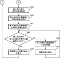
- FIG. 12 is a first flowchart for explaining the flight control process of the unmanned air vehicle according to the second embodiment of the present disclosure
- FIG. 13 is the flight control process of the unmanned air vehicle according to the second embodiment of the present disclosure
- FIG. 14 is a third flowchart for explaining the flight control processing of the unmanned air vehicle in the second embodiment of the present disclosure.
- step S31 the time measuring unit 101 acquires the current time.
- step S32 the flightable range changing unit 112 refers to the flightable range table 122 and determines whether or not the current time is a time for changing the first and second flightable ranges.
- the time when the first flightable range is changed is the same as the time when the second flightable range is changed. If it is determined that the current time is not the time for changing the first and second flightable ranges (NO in step S32), the process returns to step S31.
- step S33 the flightable range changing unit 112 determines from the sunset time to the current time.
- the first and second flightable ranges of the unmanned aerial vehicle 10 are determined according to the period of time. For example, if the time from the sunset time to the current time is 30 minutes, the flightable range changing unit 112 refers to the flightable range table 122 and first selects a hemisphere with a radius of 50 m centered on the position of the controller 20. And the second flight range is determined.
- the flightable range changing unit 112 stores the determined first and second flightable ranges as the flightable range information 125 in the storage unit 108.
- the first flightable range and the second flightable range have the same flightable distance, and the flightable range read from the flightable range table 122 is the first flightable range.
- the flightable range read from the flightable range table 122 is the first flightable range.
- the storage unit 108 stores a flightable range table 122 in which a time a predetermined time before the sunset time, the first flightable range, and the second flightable range are associated with each other.
- the first and second flightable ranges are centered on the current position of the pilot 20 and the first And a hemispherical shape having the second flightable distance as a radius.
- the first and second flightable ranges are centered on the current position of the pilot 20.
- the first and second flightable distances are circular.
- step S34 the flightable range changing unit 112 reads the pilot position information 123 from the storage unit 108, and acquires the current position of the pilot 20.
- the controller position information 123 stored in the storage unit 108 does not necessarily indicate the current position of the controller 20, but by shortening the interval at which the controller position information 123 is acquired from the controller 20. The accuracy of the current position of the controller 20 can be increased.
- the second communication unit 105 may request the current position from the controller 20 and receive the current position from the controller 20.
- step S35 the possible flight range changing unit 112 reads the VO position information 127 from the storage unit 108, and acquires the current position of the communication terminal 30.
- the VO position information 127 stored in the storage unit 108 does not necessarily indicate the current position of the communication terminal 30, but the communication can be performed by shortening the interval at which the VO position information 127 is acquired from the communication terminal 30. The accuracy of the current position of the terminal 30 can be increased.
- the second communication unit 105 may request the current position from the communication terminal 30 and receive the current position from the communication terminal 30.
- step S36 the possible flight range changing unit 112 calculates the distance between the pilot 20 and the communication terminal 30 based on the current position of the pilot 20 and the current position of the communication terminal 30.
- step S ⁇ b> 37 the flightable range changing unit 112 performs a first flightable distance that is a radius of the first flightable range centered on the controller 20 and a second flight centered on the communication terminal 30. A total value with the second flightable distance that is the radius of the flightable range is calculated.
- step S38 the flightable range changing unit 112 determines whether the distance between the pilot 20 and the communication terminal 30 is greater than the total value of the first flightable distance and the second flightable distance. Determine whether. That is, when the distance between the controller 20 and the communication terminal 30 is larger than the total value of the first flightable distance and the second flightable distance, the first flightable range and the second flightable range. It is not duplicated and is divided.
- step S39 is performed.
- the position measurement unit 102 acquires the current position of the unmanned air vehicle 10.
- step S ⁇ b> 40 the flightable range changing unit 112 calculates the distance between the unmanned air vehicle 10 and the pilot 20 based on the current position of the unmanned air vehicle 10 and the current position of the pilot 20. .
- step S41 the flightable range changing unit 112 performs the first flight of the unmanned flight vehicle 10 based on the distance between the unmanned flight vehicle 10 and the controller 20 and the first flightable range. Judge whether it exists within the possible range. That is, the flightable range changing unit 112 compares the distance between the unmanned aerial vehicle 10 and the pilot 20 with the first flightable distance, and the distance between the unmanned aircraft 10 and the pilot 20 is If the distance is equal to or shorter than the first flightable distance, it is determined that the unmanned air vehicle 10 is within the first flightable range, and the distance between the unmanned air vehicle 10 and the controller 20 is greater than the first flightable distance. If it is long, it is determined that the unmanned air vehicle 10 does not exist within the first flightable range.
- step S42 when it is determined that the unmanned air vehicle 10 is within the first flightable range (YES in step S41), in step S42, the flight control unit 111 receives an operation command from the controller 20, and receives the operation command. In response, the unmanned air vehicle 10 is caused to fly.
- the process in step S42 is the same as the process in step S8 in FIG.
- step S43 the forced movement control unit 113 determines that the unmanned air vehicle 10 is capable of the first flight.
- the unmanned air vehicle 10 is forcibly moved toward the pilot 20 so as to fall within the range.
- the forced movement control unit 113 does not accept an operation command from the controller 20 until the unmanned air vehicle 10 enters the first flightable range.
- step S44 the notification unit 114 notifies the pilot 20 that the unmanned air vehicle 10 is forcibly moved toward the pilot 20. Then, the process returns to step S41, and the forced movement control unit 113 causes the unmanned aerial vehicle 10 to automatically fly toward the controller 20 until the unmanned aerial vehicle 10 enters the first flightable range.
- step S45 the position measurement unit 102 acquires the current position of the unmanned air vehicle 10.
- step S ⁇ b> 46 the possible flight range changing unit 112 calculates the distance between the unmanned air vehicle 10 and the pilot 20 based on the current position of the unmanned air vehicle 10 and the current position of the pilot 20. .
- step S ⁇ b> 47 the flightable range changing unit 112 calculates the distance between the unmanned air vehicle 10 and the communication terminal 30 based on the current position of the unmanned air vehicle 10 and the current position of the communication terminal 30. .
- step S ⁇ b> 48 the flight range change unit 112 determines the distance between the unmanned air vehicle 10 and the controller 20, the distance between the unmanned air vehicle 10 and the communication terminal 30, and the first flight possible. Based on the range and the second flightable range, it is determined whether or not the unmanned air vehicle 10 exists within the first or second flightable range. That is, the flightable range changing unit 112 compares the distance between the unmanned aerial vehicle 10 and the pilot 20 with the first flightable distance, and the distance between the unmanned aircraft 10 and the pilot 20 is When the distance is equal to or shorter than the first flightable distance, it is determined that the unmanned air vehicle 10 exists within the first flightable range.
- the flightable range changing unit 112 compares the distance between the unmanned air vehicle 10 and the communication terminal 30 with the second flightable distance, and the distance between the unmanned air vehicle 10 and the communication terminal 30 is When the distance is equal to or shorter than the second flightable distance, it is determined that the unmanned air vehicle 10 exists within the second flightable range. Further, the flightable range changing unit 112 has a distance between the unmanned aerial vehicle 10 and the controller 20 that is longer than the first flightable distance, and a distance between the unmanned aircraft 10 and the communication terminal 30 is the second. If it is longer than the possible flight distance, it is determined that the unmanned air vehicle 10 does not exist within the first or second flightable range.
- step S48 If it is determined that the unmanned air vehicle 10 is within the first or second flightable range (YES in step S48), the flight control unit 111 receives an operation command from the pilot 20 in step S49. The unmanned air vehicle 10 is caused to fly according to the operation command. Note that the process of step S49 is the same as the process of step S8 of FIG.
- step S50 the forced movement control unit 113 determines that the unmanned aerial vehicle 10 is the first unmanned air vehicle 10.
- the unmanned aerial vehicle 10 is forcibly moved toward the controller 20 so as to fall within the flightable range of.
- the forced movement control unit 113 does not accept an operation command from the controller 20 until the unmanned air vehicle 10 enters the first flightable range.
- step S51 the notification unit 114 notifies the pilot 20 that the unmanned air vehicle 10 is forcibly moved toward the pilot 20. Then, the process returns to the process of step S48, and the forced movement control unit 113 automatically causes the unmanned air vehicle 10 to fly toward the controller 20 until the unmanned air vehicle 10 enters the first flightable range.
- FIG. 15 is a schematic diagram for explaining the division between the first flightable range and the second flightable range in the second embodiment.
- the unmanned air vehicle 10, the controller 20, and the communication terminal 30 are viewed from above.
- the flight range change unit 112 takes the first flight distance FFD1 as the radius with the pilot 20 as the center.
- the flightable range 2 is determined, and the second flightable range 4 with the communication terminal 30 as the center and the second flightable distance SFD1 as a radius is determined.
- the flight range change unit 112 When the current time becomes a second time that is closer to the sunset time than the first time, the flight range change unit 112 performs the first flight that is shorter than the first flight distance FFD1 with the controller 20 as the center.
- First flight possible range 21 having a radius of possible distance FFD2 is determined, and second flight having a radius of second flyable distance SFD2 shorter than second flightable distance SFD1 centered on communication terminal 30
- the possible range 41 is determined.
- the unmanned aerial vehicle 10 exists at an intermediate point between the controller 20 and the communication terminal 30, the unmanned aerial vehicle 10 exists in both the first flightable range 21 and the second flightable range 41. There is a possibility of disappearing. Therefore, when the first flightable range and the second flightable range are reduced and the first flightable range and the second flightable range are divided, the first flightable range and the second flightable range are divided. By notifying the controller 20 that the flightable range is divided, the unmanned air vehicle 10 is prevented from being present in either the first flightable range 21 or the second flightable range 41. be able to.
- the unmanned aerial vehicle 10 when the first flightable range and the second flightable range are divided, the unmanned aerial vehicle 10 needs to move within the first flightable range on the controller 20 side. There is. Therefore, when the first flightable range and the second flightable range are divided, the pilot 20 is notified to move into the first flightable range 2, but the present disclosure particularly deals with this. It is not limited.
- the unmanned air vehicle 10 is within the first flightable range on the controller 20 side and within the second flightable range on the communication terminal 30 side. You may move to either. In this case, when the first flightable range and the second flightable range are divided, the first flightable range 2 on the controller 20 side and the second flightable range 4 on the communication terminal 30 side You may notify the pilot 20 to move to either.
- the notification unit 114 has the first flightable range and the second flightable range before the time when the first flightable range and the second flightable range are determined by the flightable range changing unit 112. It may be estimated whether or not the unmanned air vehicle 10 exists outside the first flightable range and the second flightable range. Then, when it is estimated that the unmanned aerial vehicle 10 exists outside the first flightable range and the second flightable range, the notification unit 114 moves the unmanned aircraft 10 within the first flightable range and the second flightable range. Guidance information for guiding the user to move to any one of the flightable ranges may be notified to the controller 20.
- the unmanned air vehicle 10 will say “The flightable range is divided.
- the pilot 20 may be notified of the guidance information “Please move to either the flight range on the pilot side or the flight range on the VO side by time”.
- the controller 20 is notified that the first flightable range and the second flightable range are divided.
- the present disclosure is not particularly limited to this, and You may notify to the terminal (for example, smart phone etc.) which the operator hold
- the terminal for example, smart phone etc.
- the forced movement control unit 113 determines that the unmanned air vehicle 10 is outside the first flightable range and the second flightable range when the first flightable range and the second flightable range are determined. If present, the unmanned aerial vehicle 10 may be automatically moved toward the closer one of the controller 20 and the communication terminal 30.
- the operator or VO may move. Therefore, the division notification process shown in FIG. 11 may be executed periodically to notify that the first flightable distance and the second flightable distance are divided in real time.
- the controller 20 includes the time measuring unit 101, the flightable range changing unit 112, the forced movement control unit 113, the flightable range table 122, the forced movement program 124, the flightable range information 125, the sunset.
- Time information 126 and VO position information 127 may be provided.
- the forced movement control unit 113 is changed to a function that generates and transmits a command for forced movement control.
- the forced movement program 124 is changed to a program that generates and transmits a command for forced movement control.
- the flightable range table 122, the forced movement program 124, the flightable range information 125, the sunset time information 126, and the VO position information 127 are stored in a storage unit included in the controller 20.
- the storage unit further stores position information of the unmanned air vehicle 10. Thereby, the process performed by the unmanned air vehicle 10 can be performed by the pilot 20. Further, the VO position information 127 transmitted from the communication terminal 30 may be received by the controller 20 via a server.
- the flight control system may include the unmanned air vehicle 10, the controller 20, and the server.
- the server is connected to the controller 20 via a network.
- the server stores the time measuring unit 101, the flightable range changing unit 112, the forced movement control unit 113, the flightable range table 122, the forced movement program 124, the flightable range information 125, the sunset time information 126, and the VO position information 127.
- You may prepare.
- the forced movement control unit 113 is changed to a function that generates and transmits a command for forced movement control.
- the forced movement program 124 is changed to a program that generates and transmits a command for forced movement control.
- the flightable range table 122, the forced movement program 124, the flightable range information 125, the sunset time information 126, and the VO position information 127 are stored in a storage unit provided in the server.
- the storage unit further stores position information of the unmanned air vehicle 10.
- the information transmitted from the server may be received by the unmanned aerial vehicle 10 via the pilot 20, and the information transmitted from the unmanned aircraft 10 is received by the server via the pilot 20. May be. Further, the information transmitted from the server may be directly received by the unmanned air vehicle 10, and the information transmitted from the unmanned air vehicle 10 may be directly received by the server. Furthermore, the information transmitted from the communication terminal 30 may be received by the server via the controller 20 or may be directly received by the server.
- FIG. 16 is a schematic diagram for explaining the division of the first flightable range, the second flightable range, and the third flightable range in the second embodiment.
- the flight control system includes the unmanned air vehicle 10, the controller 20, the first communication terminal 31, and the second communication terminal 32.
- the first communication terminal 31 is operated by a first VO that monitors the unmanned air vehicle 10
- the second communication terminal 32 is a second device that monitors the unmanned air vehicle 10 at a location different from the first VO. Operated by VO.
- the configurations of the first communication terminal 31 and the second communication terminal 32 are the same as the configuration of the communication terminal 30.
- the unmanned air vehicle 10, the controller 20, the first communication terminal 31, and the second communication terminal 32 are viewed from above.
- the flight range change unit 112 performs the first flight centered on the controller 20 and having the first flight distance as a radius.
- the possible range 2 is determined
- the second flightable range 4 having the radius of the second flightable distance is determined with the first communication terminal 31 as the center
- the second communication terminal 32 is set as the center
- the third The third flightable range 5 having the radius of the flightable distance is determined.
- the flightable range changing unit 112 takes the first flightable distance as a radius around the controller 20 as a radius.
- the first flightable range 21 is determined
- the second flightable range 41 having the radius of the reduced second flightable distance is determined with the communication terminal 31 as the center
- the reduced second flight range 41 is determined with the communication terminal 32 as the center.
- a third flightable range 51 having a radius of 3 flightable distances is determined.
- the third flightable range 51 can be regarded as a part of the first flightable range 21.
- the first flightable range determined by the flightable range changing unit 112 based on the position of the pilot 20 and the position of the first communication terminal 31 operated by the first VO that monitors the unmanned air vehicle 10 are set.
- the second flight range determined as the reference and the third flight range determined based on the position of the second communication terminal 32 operated by the second VO monitoring the unmanned air vehicle 10 are determined
- the notification unit 114 Information regarding the first flightable range and the third flightable range that is not divided may be notified.
- the flight control unit 111 may control the unmanned aerial vehicle 10 so as to fly in the first flightable range and the third flightable range.
- the flightable range changing unit 112 determines the first flightable range and the third flightable range.
- the forcible movement control unit 113 is connected to the controller 20 and the second communication terminal 32.
- the unmanned aerial vehicle 10 may be automatically moved toward the side closer to the unmanned aerial vehicle 10.
- the first flight range, the second flight range, and the third flight range are reduced, the first flight range, the second flight range, and the third flight range are divided. It may overlap without being.
- FIG. 17 is a schematic diagram for explaining the overlap of the first flightable range, the second flightable range, and the third flightable range in the second embodiment.
- the flight control system includes an unmanned air vehicle 10, a controller 20, a first communication terminal 31, and a second communication terminal 32.
- the first communication terminal 31 is operated by a first VO that monitors the unmanned air vehicle 10
- the second communication terminal 32 is a second device that monitors the unmanned air vehicle 10 at a location different from the first VO. Operated by VO.
- the unmanned air vehicle 10, the controller 20, the first communication terminal 31, and the second communication terminal 32 are viewed from above.
- the flightable range changing unit 112 performs the first flight centered on the controller 20 and having the first flightable distance as a radius.
- the possible range 2 is determined
- the second flightable range 4 having the radius of the second flightable distance is determined with the first communication terminal 31 as the center
- the second communication terminal 32 is set as the center
- the third The third flightable range 5 having the radius of the flightable distance is determined.
- the flightable range changing unit 112 takes the first flightable distance as a radius around the controller 20 as a radius.
- the first flightable range 21 is determined
- the second flightable range 41 having the radius of the reduced second flightable distance is determined with the communication terminal 31 as the center
- the reduced second flight range 41 is determined with the communication terminal 32 as the center.
- a third flightable range 51 having a radius of 3 flightable distances is determined.
- the first flightable range 21 becomes the second flightable.
- the first flightable range 21 becomes the second flightable.
- it is divided from the range 41 or the second flightable range 41 is divided from the third flightable range 51.
- the unmanned aerial vehicle 10 existing in the second flightable range 41 or the third flightable range 51 cannot return to the first flightable range 21.
- the first flightable range determined by the flightable range changing unit 112 based on the position of the pilot 20 and the position of the first communication terminal 31 operated by the first VO that monitors the unmanned air vehicle 10 are set.
- the second flight range determined as the reference and the third flight range determined based on the position of the second communication terminal 32 operated by the second VO monitoring the unmanned air vehicle 10 are determined.
- the notification unit 114 The pilot 20 is notified of guidance information for guiding the unmanned air vehicle 10 to move within the first flightable range 21 or the third flightable range 51 adjacent to the first flightable range 21. Also good.
- the first flightable range 21 is the second flight.
- the third flight range is overlapped with the first flight range and the second flight range, and the unmanned air vehicle 10 has the first flight range 21 and the third flight range.
- the forced movement control unit 113 controls the unmanned air vehicle 10 to operate the unmanned air vehicle 10 so that the unmanned air vehicle 10 enters the first flightable range 21 or the third flightable range 51.
- 20 or the second communication terminal 32 may be forcibly moved.
- the first flightable range 21 is the second flight.
- the third flight range is overlapped with the first flight range and the second flight range, and the unmanned air vehicle 10 has the first flight range 21 and the third flight range.
- the forced movement control unit 113 is the unmanned aerial vehicle among the controller 20 in the first flightable range 21 and the second communication terminal 32 in the third flightable range 51.
- the unmanned air vehicle 10 may be forcibly moved toward the direction closer to 10.
- the first flight range, the second flight range, and the third flight range were reduced, and the first flight range, the second flight range, and the third flight range were divided.
- the unmanned air vehicle 10 may be moved to the widest possible flight range.
- FIG. 18 is a schematic diagram for explaining the process of moving the unmanned air vehicle to the widest flightable range among the plurality of divided flightable ranges in the second embodiment.
- the flight control system includes the unmanned air vehicle 10, the pilot 20, the first communication terminal 31, and the second communication terminal 32.
- the first communication terminal 31 is operated by a first VO that monitors the unmanned air vehicle 10
- the second communication terminal 32 is a second device that monitors the unmanned air vehicle 10 at a location different from the first VO. Operated by VO.
- the unmanned air vehicle 10, the controller 20, the first communication terminal 31, and the second communication terminal 32 are viewed from above.
- the flight range change unit 112 performs the first flight centered on the controller 20 and having the first flight distance as a radius.
- the possible range 2 is determined
- the second flightable range 4 having the radius of the second flightable distance is determined with the first communication terminal 31 as the center
- the second communication terminal 32 is set as the center
- the third The third flightable range 5 having the radius of the flightable distance is determined.
- the flightable range changing unit 112 takes the first flightable distance as a radius around the controller 20 as a radius.
- the first flightable range 21 is determined
- the second flightable range 41 having the radius of the reduced second flightable distance is determined with the communication terminal 31 as the center
- the reduced second flight range 41 is determined with the communication terminal 32 as the center.
- a third flightable range 51 having a radius of 3 flightable distances is determined.
- the reduced first flightable range 21 is the second flightable range. It is divided from the range 41 and the third flightable range 51, and a part of the reduced second flightable range 41 overlaps the reduced third flightable range 51.
- the forced movement control unit 113 calculates the area of the plurality of flightable ranges and identifies the widest flightable range among the plurality of flightable ranges. At this time, when the plurality of flightable ranges overlap, the forced movement control unit 113 sets the plurality of overlapping flightable ranges as one flightable range, and within the plurality of overlapping flightable ranges Calculate the area. For example, in the example shown in FIG. 18, since the second flightable range 41 and the third flightable range 51 overlap, the forced movement control unit 113 performs the second flightable range 41 and the third flightable range 51.
- the flightable range 51 is defined as one flightable range, and the area within the flightable range obtained by combining the second flightable range 41 and the third flightable range 51 is calculated.
- the forced movement control unit 113 forcibly moves the unmanned air vehicle 10 toward the widest possible flight range among the plurality of possible flight ranges.
- the total flightable range including the second flightable range 41 and the third flightable range 51 is wider than the first flightable range 21. Therefore, the forced movement control unit 113 forcibly moves the unmanned air vehicle 10 toward either the second flightable range 41 or the third flightable range 51. At this time, the forced movement control unit 113 forcibly moves the unmanned aerial vehicle 10 toward the nearest flightable range of the second flightable range 41 and the third flightable range 51.
- the unmanned air vehicle 10 when the first flightable range and the second flightable range are determined, the unmanned air vehicle 10 is in any of the first flightable range and the second flightable range.
- the operator may accept in advance whether or not to move. Then, when the first flightable range and the second flightable range are determined, whether the unmanned air vehicle 10 should move to the first flightable range or the second flightable range is stored in the storage unit. It may be stored in advance.
- FIG. 19 is a block diagram illustrating a configuration of an unmanned air vehicle in a modified example of the second embodiment of the present disclosure.
- 19 includes a time measurement unit 101, a position measurement unit 102, a drive unit 103, a first communication unit 104, a second communication unit 105, a battery 106, a control unit 107, and a storage unit 108.
- description of the same configuration as in the first and second embodiments is omitted.
- the control unit 107 includes a flight control unit 111, a flight range change unit 112, a forced movement control unit 113, and a notification unit 114.
- the storage unit 108 stores a basic flight program 121, a flight range table 122, a pilot position information 123, a forced movement program 124, a flight range information 125, a sunset time information 126, a VO position information 127, and a movement range information 128. .
- the movement range information 128 indicates whether the unmanned air vehicle 10 should move to the first flight range or the second flight range when the first flight range and the second flight range are determined. Is information.
- the storage unit 108 stores movement range information 128 in advance. For example, the controller 20 receives an input from the pilot of the movement range information 128 and transmits the received movement range information 128 to the unmanned air vehicle 10.
- the second communication unit 105 receives the movement range information 128 transmitted by the controller 20 and stores the received movement range information 128 in the storage unit 108.
- the forced movement control unit 113 detects the first flightable range and the first flightable range that the unmanned air vehicle 10 is represented by the movement range information 128. If it does not exist in one of the two flightable ranges, the unmanned air vehicle 10 is automatically moved toward either the first flightable range or the second flightable range stored in the storage unit 108. .
- the flightable range changing unit 112 reduces only one of the first flightable range and the second flightable range represented by the movement range information 128 every predetermined time.
- the movement range information 128 is not stored in the storage unit 108 in advance, and the unmanned air vehicle 10 has the movement range information 128 when the first flightable range and the second flightable range are actually determined.
- the forced movement control unit 113 is unmanned toward the closer of the pilot 20 and the communication terminal 30.
- the flying object 10 may be moved automatically.
- the movement range information 128 is not stored in the storage unit 108 in advance, and when the first flightable range and the second flightable range are actually determined, the unmanned air vehicle 10 has the movement range information 128 as the movement range information 128.
- the forced movement control unit 113 may automatically move the unmanned air vehicle 10 toward the pilot 20. .
- the flight control unit 111 is present in a range different from the range represented by the movement range information 128 when the first flightable range and the second flightable range are actually determined.
- the unmanned aerial vehicle 10 may be controlled to fly within a range where the unmanned aerial vehicle 10 currently exists in the first flightable range and the second flightable range.
- the flight control system may include the unmanned air vehicle 10, the controller 20, the first communication terminal 31, and the second communication terminal 32.
- the movement range information 128 is not stored in the storage unit 108 in advance, and the first flightable range, the second flightable range, and the third flightable range are determined by the flightable range changing unit 112.
- the forced movement control unit 113 may automatically move the unmanned air vehicle 10 toward the closer one of the pilot 20 and the second communication terminal 32.
- the movement range information 128 is not stored in the storage unit 108 in advance, and the first flightable range, the second flightable range, and the third flightable range are determined by the flightable range changing unit 112.
- the forced movement control unit 113 is directed to the closest one of the first communication terminal 31 and the second communication terminal 32 in the second flightable range and the third flightable range having the largest area.
- the unmanned aerial vehicle 10 may be automatically moved.
- the controller 20 includes a time measuring unit 101, a flightable range changing unit 112, a forced movement control unit 113, a flightable range table 122, a forced movement program 124, and a flightable range information. 125, sunset time information 126, VO position information 127, and movement range information 128 may be provided.
- the forced movement control unit 113 is changed to a function that generates and transmits a command for forced movement control.
- the forced movement program 124 is changed to a program that generates and transmits a command for forced movement control.
- the flightable range table 122, the forced movement program 124, the flightable range information 125, the sunset time information 126, the VO position information 127, and the movement range information 128 are stored in a storage unit provided in the controller 20.
- the storage unit further stores position information of the unmanned air vehicle 10. Thereby, the process performed by the unmanned air vehicle 10 can be performed by the pilot 20.
- the flight control system may include the unmanned air vehicle 10, the controller 20, and the server.
- the server is connected to the controller 20 via a network.
- the server includes a time measurement unit 101, a flight range change unit 112, a forced movement control unit 113, a flight range table 122, a forced movement program 124, a flight range information 125, sunset time information 126, VO position information 127, and Movement range information 128 may be provided.
- the forced movement control unit 113 is changed to a function that generates and transmits a command for forced movement control.
- the forced movement program 124 is changed to a program that generates and transmits a command for forced movement control.
- the flightable range table 122, the forced movement program 124, the flightable range information 125, the sunset time information 126, the VO position information 127, and the movement range information 128 are stored in a storage unit provided in the server.
- the storage unit further stores position information of the unmanned air vehicle 10.
- the information transmitted from the server may be received by the unmanned aerial vehicle 10 via the pilot 20, and the information transmitted from the unmanned aircraft 10 is received by the server via the pilot 20. May be. Further, the information transmitted from the server may be directly received by the unmanned air vehicle 10, and the information transmitted from the unmanned air vehicle 10 may be directly received by the server. Furthermore, the information transmitted from the communication terminal 30 may be received by the server via the controller 20 or may be directly received by the server.
- all or part of a unit, device, member, or part, or all or part of functional blocks in the block diagrams shown in FIGS. 3, 4, 5, 12, 18, 19, and 22 are semiconductor devices, It may be executed by one or a plurality of electronic circuits including a semiconductor integrated circuit (IC) or LSI (Large Scale Integration).
- the LSI or IC may be integrated on a single chip, or may be configured by combining a plurality of chips.
- the functional blocks other than the memory element may be integrated on one chip.
- it is called LSI or IC, but the name changes depending on the degree of integration and may be called system LSI, VLSI (Very Large Scale Integration), or ULSI (Ultra Large Scale Integration).
- FPGA Field Programmable Gate Array
- a Reconfigurable Logic Device that can reconfigure the connection relationship inside the LSI or set up the circuit partition inside the LSI can be used for the same purpose.
- the software is recorded on a non-temporary recording medium such as one or more ROMs, optical disks, hard disk drives, etc., and is specified by the software when the software is executed by a processor.
- Functions are executed by a processor and peripheral devices.
- the system or apparatus may include one or more non-transitory recording media in which software is recorded, a processor, and required hardware devices such as an interface.
- the unmanned air vehicle, the flight control method, the flight basic program, and the forced movement program according to the present disclosure can return the unmanned air vehicle by the end time of the time zone in which the unmanned air vehicle is permitted to fly, It is useful as an unmanned aerial vehicle that flies by the above, a flight control method that controls the flight of an unmanned aerial vehicle that flies by remote control, a basic flight program, and a forced movement program.
- Pilot 3 VO DESCRIPTION OF SYMBOLS 10 Unmanned air vehicle 20 Pilot 30 Communication terminal 31 1st communication terminal 32 2nd communication terminal 101 Time measurement part 102 Position measurement part 103 Drive part 104 1st communication part 105 2nd communication part 106 Battery 107 Control part 108 Storage Unit 111 Flight control unit 112 Flight range change unit 113 Forced movement control unit 114 Notification unit 121 Basic flight program 122 Flight range table 123 Control device position information 124 Forced movement program 125 Flight range information 126 Time information 127 VO position information 128 Movement range information 201 Control unit 202 Position measurement unit 203 Battery 204 Display unit 205 Operation command input unit 206 First wireless communication unit 207 Second wireless communication unit 301 Battery 302 Control unit 303 Position measurement unit 304 Microphone 3 5 speaker 306 display unit 307 input unit 308 wireless communication unit 1001 various sensors 1002 propulsor
Abstract
La présente invention concerne un véhicule de vol sans pilote (10) comprenant les éléments suivants : une unité de mesure de temps (101) qui acquiert l'instant de temps courant ; une unité de changement de plage de vol possible (112) qui détermine une plage de vol possible du véhicule de vol sans pilote (10) en fonction du temps depuis l'instant de temps de fin d'une période de temps pendant laquelle le véhicule de vol sans pilote (10) est autorisé à voler jusqu'à l'instant de temps courant ; et une unité de commande de vol (111) qui commande le véhicule de vol sans pilote (10) de manière à voler dans la plage de vol possible.
Priority Applications (4)
| Application Number | Priority Date | Filing Date | Title |
|---|---|---|---|
| CN201680015750.3A CN107405529B (zh) | 2015-07-17 | 2016-06-30 | 无人飞行器、飞行控制方法、飞行基本程序和强制移动程序 |
| CN202010082731.0A CN111532427B (zh) | 2015-07-17 | 2016-06-30 | 无人飞行器、方法和存储介质 |
| US15/730,884 US10223923B2 (en) | 2015-07-17 | 2017-10-12 | Drone, method for controlling flight, and recording medium storing program |
| US16/249,215 US11551559B2 (en) | 2015-07-17 | 2019-01-16 | Drone, method for controlling flight, and recording medium storing program |
Applications Claiming Priority (6)
| Application Number | Priority Date | Filing Date | Title |
|---|---|---|---|
| US201562193680P | 2015-07-17 | 2015-07-17 | |
| US62/193,680 | 2015-07-17 | ||
| JP2015210330 | 2015-10-27 | ||
| JP2015-210330 | 2015-10-27 | ||
| JP2016123242A JP6657030B2 (ja) | 2015-07-17 | 2016-06-22 | 無人飛行体、飛行制御方法、飛行基本プログラム及び強制移動プログラム |
| JP2016-123242 | 2016-06-22 |
Related Child Applications (1)
| Application Number | Title | Priority Date | Filing Date |
|---|---|---|---|
| US15/730,884 Continuation US10223923B2 (en) | 2015-07-17 | 2017-10-12 | Drone, method for controlling flight, and recording medium storing program |
Publications (1)
| Publication Number | Publication Date |
|---|---|
| WO2017013840A1 true WO2017013840A1 (fr) | 2017-01-26 |
Family
ID=57834063
Family Applications (1)
| Application Number | Title | Priority Date | Filing Date |
|---|---|---|---|
| PCT/JP2016/003142 WO2017013840A1 (fr) | 2015-07-17 | 2016-06-30 | Véhicule de vol sans pilote, procédé de commande de vol, programme de base de vol, et programme de mouvement forcé |
Country Status (2)
| Country | Link |
|---|---|
| CN (1) | CN111532427B (fr) |
| WO (1) | WO2017013840A1 (fr) |
Cited By (2)
| Publication number | Priority date | Publication date | Assignee | Title |
|---|---|---|---|---|
| JP2018115863A (ja) * | 2017-01-16 | 2018-07-26 | 株式会社Subaru | 移動体の運行管理装置、移動体の運行管理方法、及び移動体の運行管理プログラム |
| WO2019169574A1 (fr) * | 2018-03-07 | 2019-09-12 | 深圳市大疆创新科技有限公司 | Procédé et dispositif de gestion de vol nocturne d'un véhicule aérien sans pilote |
Citations (3)
| Publication number | Priority date | Publication date | Assignee | Title |
|---|---|---|---|---|
| JP2007237873A (ja) * | 2006-03-08 | 2007-09-20 | Mitsubishi Electric Corp | 移動機制御装置及び移動機制御方法及びプログラム |
| JP2014041601A (ja) * | 2012-06-25 | 2014-03-06 | Boeing Co | 予測不可能なビークルナビゲーション |
| JP2014199548A (ja) * | 2013-03-29 | 2014-10-23 | 綜合警備保障株式会社 | 飛行制御システム及び飛行制御方法 |
Family Cites Families (19)
| Publication number | Priority date | Publication date | Assignee | Title |
|---|---|---|---|---|
| JP3946857B2 (ja) * | 1998-03-03 | 2007-07-18 | アルゼ株式会社 | 競争ゲーム装置 |
| JP4017448B2 (ja) * | 2002-06-14 | 2007-12-05 | 財団法人くまもとテクノ産業財団 | 自律飛行カイトプレーンシステムおよびカイトプレーン制御装置 |
| CA2444827C (fr) * | 2003-10-10 | 2011-11-29 | Nav Canada | Architecture de base de donnees pour un systeme d'information sur le trafic aerien |
| US7512462B2 (en) * | 2004-11-16 | 2009-03-31 | Northrop Grumman Corporation | Automatic contingency generator |
| DE102009018616A1 (de) * | 2009-04-23 | 2010-10-28 | Siemens Aktiengesellschaft | Verfahren zum Betrieb eines Schienenfahrzeugs |
| US8725402B2 (en) * | 2009-11-13 | 2014-05-13 | The Boeing Company | Loss of separation avoidance maneuvering |
| EP2559018A4 (fr) * | 2010-04-12 | 2014-01-08 | Flight Focus Pte Ltd | Système embarqué d'établissement du plan de vol |
| US8606491B2 (en) * | 2011-02-22 | 2013-12-10 | General Electric Company | Methods and systems for managing air traffic |
| US8942914B2 (en) * | 2011-02-22 | 2015-01-27 | General Electric Company | Methods and systems for managing air traffic |
| US8676406B2 (en) * | 2011-05-03 | 2014-03-18 | Raytheon Company | Unmanned aerial vehicle control using a gamepad |
| US20130124089A1 (en) * | 2011-11-11 | 2013-05-16 | Lockheed Martin Corporation | Spatiotemporal survivability data compression using objective oriented constraints |
| JP5863515B2 (ja) * | 2012-03-02 | 2016-02-16 | 三菱重工業株式会社 | 飛しょう体の制御装置及び飛しょう体の制御方法 |
| CN103217985B (zh) * | 2012-10-31 | 2016-06-29 | 上海大学 | 基于双飞行机器人对有源目标的协调搜寻方法与系统 |
| EP2781980B2 (fr) * | 2013-03-19 | 2021-12-08 | The Boeing Company | Procédé de vol d'un véhicule aérien sans pilote |
| CN107168360B (zh) * | 2013-07-05 | 2021-03-30 | 深圳市大疆创新科技有限公司 | 无人飞行器的飞行辅助方法和装置 |
| CN103914076B (zh) * | 2014-03-28 | 2017-02-15 | 浙江吉利控股集团有限公司 | 一种基于无人机的货物传送系统和方法 |
| CN103995540A (zh) * | 2014-05-22 | 2014-08-20 | 哈尔滨工业大学 | 一种高超声速飞行器的有限时间轨迹快速生成方法 |
| CN106803363A (zh) * | 2015-01-07 | 2017-06-06 | 江苏理工学院 | 一种基于4d航迹的飞行冲突解脱方法 |
| US9601022B2 (en) * | 2015-01-29 | 2017-03-21 | Qualcomm Incorporated | Systems and methods for restricting drone airspace access |
-
2016
- 2016-06-30 WO PCT/JP2016/003142 patent/WO2017013840A1/fr active Application Filing
- 2016-06-30 CN CN202010082731.0A patent/CN111532427B/zh active Active
Patent Citations (3)
| Publication number | Priority date | Publication date | Assignee | Title |
|---|---|---|---|---|
| JP2007237873A (ja) * | 2006-03-08 | 2007-09-20 | Mitsubishi Electric Corp | 移動機制御装置及び移動機制御方法及びプログラム |
| JP2014041601A (ja) * | 2012-06-25 | 2014-03-06 | Boeing Co | 予測不可能なビークルナビゲーション |
| JP2014199548A (ja) * | 2013-03-29 | 2014-10-23 | 綜合警備保障株式会社 | 飛行制御システム及び飛行制御方法 |
Cited By (3)
| Publication number | Priority date | Publication date | Assignee | Title |
|---|---|---|---|---|
| JP2018115863A (ja) * | 2017-01-16 | 2018-07-26 | 株式会社Subaru | 移動体の運行管理装置、移動体の運行管理方法、及び移動体の運行管理プログラム |
| WO2019169574A1 (fr) * | 2018-03-07 | 2019-09-12 | 深圳市大疆创新科技有限公司 | Procédé et dispositif de gestion de vol nocturne d'un véhicule aérien sans pilote |
| CN110603425A (zh) * | 2018-03-07 | 2019-12-20 | 深圳市大疆创新科技有限公司 | 无人机的夜间飞行管理方法和设备 |
Also Published As
| Publication number | Publication date |
|---|---|
| CN111532427B (zh) | 2023-07-28 |
| CN111532427A (zh) | 2020-08-14 |
Similar Documents
| Publication | Publication Date | Title |
|---|---|---|
| JP2017077878A (ja) | 無人飛行体、飛行制御方法、飛行基本プログラム及び強制移動プログラム | |
| JP7225443B2 (ja) | 飛行ルート生成方法及びプログラム | |
| JP6179000B2 (ja) | 飛行情報を提供する方法、プログラム及び端末 | |
| US10310617B2 (en) | Drone controlling device and method | |
| US20200019189A1 (en) | Systems and methods for operating unmanned aerial vehicle | |
| US11599110B2 (en) | Notification method, notification device, and terminal | |
| AU2017357923A1 (en) | Safety system for operation of an unmanned aerial vehicle | |
| WO2018075160A1 (fr) | Navigation à travers des zones polygonales interdites au survol | |
| US9857794B1 (en) | System for controlling position and speed of a marine vessel | |
| US11837097B2 (en) | Method of displaying flight route of unmanned aerial vehicle that flies autonomously, terminal, and non-transitory computer-readable recording medium storing program | |
| WO2017013840A1 (fr) | Véhicule de vol sans pilote, procédé de commande de vol, programme de base de vol, et programme de mouvement forcé | |
| JP6915109B2 (ja) | 無人飛行体、方法及びプログラム | |
| JP2019114036A (ja) | 情報処理装置、飛行制御指示方法、プログラム、及び記録媒体 | |
| JP6856670B2 (ja) | 飛行体、動作制御方法、動作制御システム、プログラム及び記録媒体 | |
| CN111226181A (zh) | 一种可移动平台的控制方法、设备及可移动平台 | |
| EP4309999A1 (fr) | Système de commande de vol | |
| US20240153390A1 (en) | Flight management system, flight management method, and flight management program for multiple aerial vehicles |
Legal Events
| Date | Code | Title | Description |
|---|---|---|---|
| 121 | Ep: the epo has been informed by wipo that ep was designated in this application |
Ref document number: 16827408 Country of ref document: EP Kind code of ref document: A1 |
|
| NENP | Non-entry into the national phase |
Ref country code: DE |
|
| 122 | Ep: pct application non-entry in european phase |
Ref document number: 16827408 Country of ref document: EP Kind code of ref document: A1 |