WO2017006818A1 - Dispositif de prévention d'adhésion de corps étranger, et dispositif appareil photo le comprenant - Google Patents
Dispositif de prévention d'adhésion de corps étranger, et dispositif appareil photo le comprenant Download PDFInfo
- Publication number
- WO2017006818A1 WO2017006818A1 PCT/JP2016/069231 JP2016069231W WO2017006818A1 WO 2017006818 A1 WO2017006818 A1 WO 2017006818A1 JP 2016069231 W JP2016069231 W JP 2016069231W WO 2017006818 A1 WO2017006818 A1 WO 2017006818A1
- Authority
- WO
- WIPO (PCT)
- Prior art keywords
- foreign matter
- matter adhesion
- adhesion preventing
- cover member
- nozzle
- Prior art date
Links
Images


Classifications
-
- B—PERFORMING OPERATIONS; TRANSPORTING
- B60—VEHICLES IN GENERAL
- B60S—SERVICING, CLEANING, REPAIRING, SUPPORTING, LIFTING, OR MANOEUVRING OF VEHICLES, NOT OTHERWISE PROVIDED FOR
- B60S1/00—Cleaning of vehicles
- B60S1/02—Cleaning windscreens, windows or optical devices
- B60S1/46—Cleaning windscreens, windows or optical devices using liquid; Windscreen washers
- B60S1/48—Liquid supply therefor
- B60S1/52—Arrangement of nozzles; Liquid spreading means
-
- B—PERFORMING OPERATIONS; TRANSPORTING
- B60—VEHICLES IN GENERAL
- B60S—SERVICING, CLEANING, REPAIRING, SUPPORTING, LIFTING, OR MANOEUVRING OF VEHICLES, NOT OTHERWISE PROVIDED FOR
- B60S1/00—Cleaning of vehicles
- B60S1/02—Cleaning windscreens, windows or optical devices
- B60S1/56—Cleaning windscreens, windows or optical devices specially adapted for cleaning other parts or devices than front windows or windscreens
-
- G—PHYSICS
- G02—OPTICS
- G02B—OPTICAL ELEMENTS, SYSTEMS OR APPARATUS
- G02B27/00—Optical systems or apparatus not provided for by any of the groups G02B1/00 - G02B26/00, G02B30/00
- G02B27/0006—Optical systems or apparatus not provided for by any of the groups G02B1/00 - G02B26/00, G02B30/00 with means to keep optical surfaces clean, e.g. by preventing or removing dirt, stains, contamination, condensation
-
- G—PHYSICS
- G03—PHOTOGRAPHY; CINEMATOGRAPHY; ANALOGOUS TECHNIQUES USING WAVES OTHER THAN OPTICAL WAVES; ELECTROGRAPHY; HOLOGRAPHY
- G03B—APPARATUS OR ARRANGEMENTS FOR TAKING PHOTOGRAPHS OR FOR PROJECTING OR VIEWING THEM; APPARATUS OR ARRANGEMENTS EMPLOYING ANALOGOUS TECHNIQUES USING WAVES OTHER THAN OPTICAL WAVES; ACCESSORIES THEREFOR
- G03B17/00—Details of cameras or camera bodies; Accessories therefor
- G03B17/02—Bodies
-
- H—ELECTRICITY
- H04—ELECTRIC COMMUNICATION TECHNIQUE
- H04N—PICTORIAL COMMUNICATION, e.g. TELEVISION
- H04N23/00—Cameras or camera modules comprising electronic image sensors; Control thereof
- H04N23/50—Constructional details
-
- B—PERFORMING OPERATIONS; TRANSPORTING
- B08—CLEANING
- B08B—CLEANING IN GENERAL; PREVENTION OF FOULING IN GENERAL
- B08B3/00—Cleaning by methods involving the use or presence of liquid or steam
- B08B3/02—Cleaning by the force of jets or sprays
-
- G—PHYSICS
- G03—PHOTOGRAPHY; CINEMATOGRAPHY; ANALOGOUS TECHNIQUES USING WAVES OTHER THAN OPTICAL WAVES; ELECTROGRAPHY; HOLOGRAPHY
- G03B—APPARATUS OR ARRANGEMENTS FOR TAKING PHOTOGRAPHS OR FOR PROJECTING OR VIEWING THEM; APPARATUS OR ARRANGEMENTS EMPLOYING ANALOGOUS TECHNIQUES USING WAVES OTHER THAN OPTICAL WAVES; ACCESSORIES THEREFOR
- G03B17/00—Details of cameras or camera bodies; Accessories therefor
- G03B17/02—Bodies
- G03B17/08—Waterproof bodies or housings
Definitions
- the present invention relates to a foreign matter adhesion preventing device, and in particular, foreign matter such as raindrops, dust, and mud adheres to a lens portion (photographing surface) of a camera device (camera body) such as an in-vehicle camera attached to an exterior portion of a vehicle. It relates to a device for preventing.
- the in-vehicle camera which is a back monitor camera, is installed on, for example, a lower part of a body spoiler, a recess around a license plate, an upper part of a back door or a flat back door surface.
- an in-vehicle camera that is an around monitor camera is also attached to the bottom surface of a door mirror (side mirror) of a vehicle body. Since such a vehicle-mounted camera is installed outside the vehicle body, it is necessary to keep dustproof and waterproof.
- the lens part (photographing surface) of the in-vehicle camera often has foreign matters such as raindrops, dust and mud. Therefore, conventionally, a foreign substance is removed by spraying a fluid such as a liquid such as a cleaning liquid onto a lens portion (photographing surface) of an in-vehicle camera.
- Patent Document 1 discloses a camera body having a housing and a lens (photographing window portion of the photographing surface) provided in the housing, and a camera nozzle that supplies a cleaning liquid toward the lens (photographing window portion of the photographing surface).
- “In-vehicle camera with washer nozzle” is disclosed.
- Patent Document 1 has the following problems.
- the shape of the camera nozzle must be designed in accordance with the outer shape of the camera body. In particular, it is necessary to adjust the position (angle) of the discharge portion (discharge port) of the nozzle so that a liquid such as a cleaning liquid is appropriately supplied toward the photographing window portion of the photographing surface of the camera body.
- the vehicle-mounted camera with a washer nozzle disclosed in Patent Document 1 has a problem that it lacks versatility.
- a liquid such as a cleaning liquid is directly discharged toward the photographing window portion of the photographing surface of the camera body exposed to the outside. Therefore, after the liquid is discharged, the imaging surface (imaging window portion) of the camera body is wet with the liquid.
- the vehicle-mounted camera disclosed in Patent Document 1 also has a problem that dust or the like reattaches to the wet imaging surface (imaging window portion). In order to solve this problem, it is necessary to continuously discharge the liquid or to always discharge the liquid at a short interval. However, this causes a new problem that the cleaning liquid must be replenished frequently.
- an object of the present invention is to provide a highly versatile foreign matter adhesion preventing apparatus capable of preventing foreign matter from directly adhering to the photographing surface of the camera body and a camera device equipped with the same.
- the terms “upper”, “upper”, “upper” and “upper” indicate the subject side in the direction of the optical axis O in the camera apparatus (camera body) of the present invention.
- 2 shows the image sensor side in the optical axis O direction in the camera device (camera body) of the present invention.
- the foreign matter adhesion prevention device is used by being attached to a camera body having a photographing surface exposed to the outside, and prevents foreign matter from adhering to the photographing surface.
- the foreign matter adhesion preventing apparatus includes a cover having a cover member that covers the imaging surface, and a nozzle that sprays fluid toward the outer surface of the cover member.
- a camera device having the foreign matter adhesion preventing device and a camera body to which the foreign matter adhesion preventing device is attached.
- the present invention it is possible to provide a highly versatile foreign matter adhesion preventing apparatus capable of preventing foreign matter from directly adhering to the photographing surface of the camera body and a camera device including the same.
- FIG. 2 is an external perspective view of the camera device illustrated in FIG. 1.
- FIG. 3 is a front view of the camera device illustrated in FIG. 2.
- FIG. 3 is a plan view of the camera device illustrated in FIG. 2.
- FIG. 3 is a right side view of the camera device illustrated in FIG. 2.
- FIG. 3 is a bottom view of the camera device illustrated in FIG. 2. It is the perspective view which looked at the foreign material adhesion prevention apparatus used for the camera apparatus shown in FIG. 1 from the bottom face side.
- FIG. 8 is an exploded perspective view of the foreign matter adhesion preventing apparatus shown in FIG. 7. It is sectional drawing about line IX-IX of FIG. FIGS.
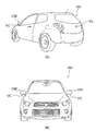
- FIG. 3A and 3B are diagrams illustrating a state in which the camera device illustrated in FIG. 2 is attached to an automobile AM as an in-vehicle camera VC, where FIG. 3A is a perspective view of the automobile AM viewed from the rear side, and FIG. It is the front view seen from the side.
- the illustrated camera device 10 includes an in-vehicle camera used as a back monitor camera at the rear of the vehicle body.
- the camera device 10 may be an in-vehicle camera used as an around monitor camera attached to the bottom surface of a door mirror (side mirror) of the vehicle body.
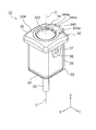
- FIG. 1 is an exploded perspective view of the camera apparatus 10.
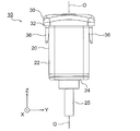
- FIG. 2 is an external perspective view of the camera apparatus 10.
- FIG. 3 is a front view of the camera apparatus 10.
- FIG. 4 is a plan view of the camera device 10.
- FIG. 5 is a right side view of the camera apparatus 10.
- FIG. 6 is a bottom view of the camera apparatus 10.
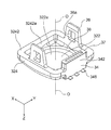
- FIG. 7 is a perspective view of the foreign matter adhesion preventing apparatus 30 as viewed from the bottom surface side
- FIG. 8 is an exploded perspective view of the foreign matter adhesion preventing apparatus 30.
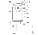
- 9 is a cross-sectional view taken along line IX-IX in FIG.
- an orthogonal coordinate system (X, Y, Z) is used.
- the X-axis direction is the front-rear direction (depth direction)
- the Y-axis direction is the left-right direction (width direction)
- Z The axial direction is the vertical direction (height direction).
- the vertical direction Z is the direction of the optical axis O of the lens.
- the upward direction of the vertical direction Z is a direction in which a subject (not shown) exists.
- the Y-axis direction (left-right direction) is also called a first direction
- the X-axis direction (front-rear direction) is also called a second direction.
- the illustrated camera device 10 is composed of two components. That is, the camera device 10 includes a camera body 20 and a foreign matter adhesion preventing device 30.
- the camera body 20 includes a lens group 21, a holding member 22 that holds the lens group 21, a retainer 23 provided at the upper end of the holding member 22, and a sealing member provided at the lower end of the holding member 22. 24 and a cable 25 extending from the sealing member 24 to the outside.
- “sealing” means closing the opening.
- the lens group 21 is composed of a plurality of lenses. In FIG. 1, only the uppermost upper lens 211 among the plurality of lenses constituting the lens group 21 is illustrated. In the illustrated lens group 21, each of the plurality of lenses has a circular outer shape.
- the holding member 22 has a substantially rectangular tube shape extending in the vertical direction Z.
- the holding member 22 has an internal space divided into a lens housing space for housing the lens group 21 and a substrate housing space for housing a substrate unit (not shown).
- the holding member 22 has a retainer receiving surface (not shown) for receiving the retainer 23 at its upper end.
- the retainer 23 is a member for preventing water from entering the holding member 22.
- the retainer 23 is attached to the upper end of the holding member 22.
- the retainer 23 is provided so as to protrude substantially upward and inward from the outer cylinder part 232 at the upper end of the outer cylinder part 232 at a substantially square cylindrical outer cylinder part 232 extending in the vertical direction Z.
- an upper end portion 234 having a curved ring shape.
- the upper end 234 has a substantially circular opening (not shown) that matches the outer shape of the lens group 21.
- the outer cylinder part 232 of the retainer 23 is received by the retainer receiving surface of the holding member 22.
- the upper surface 211a of the uppermost upper lens 211 of the lens group 21 is exposed from the opening of the upper end portion 234 of the retainer 23. That is, the retainer 23 is attached to the upper end portion of the holding member 22 so as to surround the outer peripheral edge of the upper lens 211 with the upper surface 211a of the upper lens 211 exposed.
- the illustrated camera body 20 has the upper surface 211a of the upper lens 211 as a photographing surface exposed to the outside.
- the imaging surface exposed to the outside includes the upper surface 211a of the upper lens 211, but the present invention is not limited to this.
- the photographing surface exposed to the outside may be a photographing window portion as described in Patent Document 1.
- the substrate unit includes a sensor substrate and a power supply substrate.
- An image sensor is mounted on the sensor substrate.
- the imaging device captures the subject image formed by the lens group 21 and converts it into an electrical signal.
- the image pickup device includes, for example, a charge coupled device (CCD) image sensor, a complementary metal oxide semiconductor (CMOS) image sensor, and the like.
- CCD charge coupled device
- CMOS complementary metal oxide semiconductor
- the sensor board and the power supply board are fitted via an inter-board connector.
- the tip of the cable 25 is electrically connected to the power supply board by solder or the like.
- the illustrated camera body 20 has a substantially quadrangular prism shape.
- a camera device such as an on-vehicle camera that is generally commercially available has a substantially quadrangular prism outer shape like the outer shape of the camera body 20 shown in FIG. That is, it should be noted that generally commercially available camera devices may have substantially the same vertical and horizontal dimensions, although their height may vary.
- the combination of the holding member 22, the retainer 23, and the sealing member 24 serves as a housing for the camera body 20.
- the camera body 20 further includes a supply pipe 26 having a supply port for supplying a fluid to a nozzle 34 of a foreign matter adhesion prevention device 30 described later.
- the supply pipe 26 extends in the up-down direction Z on the back surface of the holding member 22.
- the supply pipe 26 is a rectangular pipe that is wide in the left-right direction (first direction) Y.
- the fluid consists of air.
- a substantially cylindrical insertion portion 28 is provided at the lower end portion of the supply pipe 26 so as to protrude.
- One end of a hose (not shown) is inserted into the insertion portion 28.
- An air supply source such as a pump (not shown) is connected to the other end of the hose.
- the fluid is not limited to air and may be a liquid such as a cleaning liquid.
- the camera body 20 has a pair of protrusions (protrusions) protruding outward at positions close to the retainer 23 on both side surfaces of the holding member 22 in the left-right direction (first direction) Y. Part) 27 (however, in FIG. 1, only the right protrusion is shown).
- holes (concave portions) 36 a of a pair of fasteners 36 of the foreign matter adhesion preventing device 30 described later are fitted into the pair of protrusions 27. Therefore, the combination of the pair of protrusions 27 of the camera body 20 and the fastener 36 of the foreign matter adhesion preventing device 30 functions as a snap fit.
- the foreign matter adhesion preventing device 30 can be easily attached to the camera body 20. In other words, the work of attaching the foreign matter adhesion preventing device 30 to the camera body 20 can be improved.
- the snap fit is configured by providing the convex portion 27 on the camera body 20 side and the concave portion 36a on the foreign matter adhesion preventing device 30 side, but the reverse may be possible. That is, the snap fit may be configured by providing a concave portion on the camera body 20 side and providing a convex portion on the foreign matter adhesion preventing device 30 side.
- the fastener 36 of the foreign matter adhesion preventing device 30 serves as an attachment member for attaching the foreign matter adhesion preventing device 30 to the camera body 20.
- the foreign matter adhesion preventing device 30 is used by being mounted on the camera body 20 having the photographing surface 211a exposed to the outside.
- the foreign matter adhesion preventing device 30 is a device for preventing foreign matter from adhering to the imaging surface 211a.
- the foreign matter is composed of, for example, raindrops, insects, sand dust, mud and the like.
- the foreign matter adhesion preventing apparatus 30 includes a cover 32 having a cover member 322 that covers the imaging surface 211a, and a nozzle 34 that sprays fluid toward the outer surface 322b of the cover member 322.
- the fluid consists of air.
- air may be continuously blown to the outer surface 322b of the cover member 322, or when a switch (not shown) installed in the vehicle is pressed, the air is directed to the outer surface 322b of the cover member 322 only for a predetermined time. Air may be blown continuously.
- the illustrated cover member 322 has a circular shape in plan view, and is formed in a thin film shape. Therefore, the cover member 322 is also called a cover film.
- the diameter of the cover member 322 is larger than the diameter of the upper lens 211 (photographing surface 211a) of the camera body 20.
- the cover 32 has a peripheral portion 324 provided outside the cover member 322 in the radial direction.
- the peripheral portion 324 includes a square cylindrical mounting portion 3242 and an upper end holding portion 3244.
- the rectangular cylindrical mounting portion 3242 has a substantially rectangular opening 3242 a having a dimension substantially equal to the outer shape (dimension) of the holding member 22 of the camera body 20, and the holding member of the camera body 20. 22 is attached.
- the upper end holding portion 3244 is provided between the mounting portion 3242 and the cover member 322 and holds the cover member ⁇ cover film> 322.
- the nozzle 34 is provided at an introduction pipe 342 having an introduction port 342 a having substantially the same opening shape as the supply port of the supply pipe 26, and a distal end portion of the introduction pipe 342.
- the introduction pipe 342 is a rectangular pipe extending in the up-down direction Z on the back side of the holding member 22 of the camera body 20.
- the discharge portion 344 has three injection holes 344 a (see FIG. 1) that communicate with the flow path of the introduction pipe 342 and extend in the front-rear direction X.
- the foreign matter adhesion preventing device 30 includes a gasket 37 attached between the introduction port 342 a of the introduction tube 342 and the supply port of the supply tube 26.
- the gasket 37 is attached to the introduction port 342a and the supply port using, for example, a double-sided tape. Thereby, the airtightness between the introduction pipe 342 and the supply pipe 26 is ensured.
- the cover 32, the nozzle 34, and the pair of fasteners 36 are integrally configured. Specifically, the cover 32, the nozzle 34, and the pair of fasteners 36 are integrally formed of resin by injection molding.
- the three windows 346a are closed by thermal welding, but may be closed by other methods.
- the three resin pieces 346 may not be formed, and the three windows 346a may be sealed with resin, or may be bonded after inserting three resin parts into the three windows 346a. It may be closed.
- the resin constituting the foreign matter adhesion preventing apparatus 30 is made of a transparent resin.
- a transparent resin for example, an acrylic resin or a polycarbonate resin can be used.
- the outer wall surface of the transparent resin constituting the foreign matter adhesion preventing apparatus 30 is coated with a coating material 30a made of a material that blocks light, except for the cover member 322.
- a coating material 30a made of a material that blocks light, except for the cover member 322.
- the cover member 322 has an antireflection film 322a formed on the inner surface of the camera body 20 facing the imaging surface 211a. Also by this, it is possible to prevent ghosts and flares in an image captured by the image sensor of the camera body 20.
- the cover member 322 is provided as a single paragraph from the upper end holding portion 3244 in the vicinity thereof. Thereby, it is possible to prevent insects, dust, mud, and the like from adhering to the outer surface 322b of the cover member 322.
- the illustrated cover member 322 has a curved shape protruding outward.
- FOV field of view
- AOV angle of view
- a chamfered portion 3244 a is applied to a part of the cover member 322 that is one stage. This also secures the field of view or the angle of view of the camera body 20.
- the foreign matter adhesion preventing device 30 further includes an O-ring 38 that is mounted between the inner wall of the peripheral portion 324 of the cover 32 and the outer wall of the camera body 20. Thereby, the space (gap) between the camera body 20 and the cover 32 of the foreign matter adhesion preventing apparatus 30 can be sealed. As a result, it is possible to prevent moisture from entering the gap between the camera body 20 and the cover 32.
- the nozzle output diameter Dno at the tip of the nozzle 34 (that is, the tip of the three injection holes 344 a of the discharge unit 344) is reduced. .
- the nozzle output diameter Dno at the tip of the nozzle 34 that is, the tip of the three injection holes 344 a of the discharge unit 344.
- the angle of the tip of the injection hole 344a with respect to the outer surface 322b of the cover member 322 is shallow.
- the chamfered portion 3244a located on the opposite side is reached without being separated.
- the fluid exiting the injection hole 344a has a small separation component that dissipates from the outer surface 322b of the cover member 322, and most of the fluid contributes to the removal of foreign matter, so the foreign matter removal efficiency is high.
- the outer surface 322b of the cover member 322 is subjected to water repellent finishing. This makes it possible to efficiently repel raindrops that may adhere to the outer surface 322b of the cover member 322.
- the foreign matter adhesion preventing apparatus 30 includes the cover 32 that covers the imaging surface 211a of the camera body 20, and thus the foreign matter directly on the imaging surface 211a. Can be prevented from adhering. Moreover, since the foreign material adhesion preventing device 30 has a configuration that can be easily attached to a commercially available camera device, versatility can be improved. In addition, when air is used as the fluid, it is possible to save the trouble of replenishing the liquid and prevent the dust from reattaching compared to the case where a liquid such as a cleaning liquid is used as the fluid. Become.
- FIG. 10 is a diagram showing a state in which the camera device 10 is attached to the automobile AM as the in-vehicle camera VC.
- 10A is a perspective view of the automobile AM viewed from the rear side
- FIG. 10B is a front view of the automobile AM viewed from the front side.
- the camera device 10 is attached to the rear part of the vehicle AM as a back monitor camera VC using an attachment member (not shown).
- the camera apparatus 10 has an attachment member (not shown) as an around monitor camera VC on the bottom surface of the door mirror (side mirror) OM of the automobile AM. Installed using.
- foreign matter adhesion prevention is used by attaching to a camera body (20) having a photographing surface (211a) exposed to the outside and preventing foreign matter from adhering to the photographing surface (211a).
- a foreign matter adhesion preventing apparatus having the above can be obtained.
- the cover (32) and the nozzle (34) are integrally formed. More preferably, the cover (32) and the nozzle (34) are integrally formed of resin by injection molding. In that case, it is desirable that the window (346a) formed in the flow path of the nozzle (34) at the time of injection molding is closed by any one of thermal welding, resin encapsulation, and component adhesion.
- the resin is preferably made of a transparent resin. In that case, it is desirable that the outer wall surface of the transparent resin is painted with a coating material (30a) made of a material that blocks light except for the cover member (322).
- the cover member (322) is provided as a single paragraph from the surrounding resin (324). In that case, it is desirable that the cover member (322) has a curved surface shape, and it is desirable that a chamfered portion (3244a) is applied to a part of the cover member (322) which is one stage.
- the foreign matter adhesion preventing device (30) preferably has an attachment member (36) for attaching the foreign matter adhesion preventing device (30) to the camera body (20).
- the cover (32) may include a peripheral portion (324) provided around the cover member (322) and attached to the camera body (20).
- the foreign matter adhesion preventing device (30) further includes an O-ring (38) mounted between the inner wall of the peripheral portion (324) of the cover (32) and the outer wall of the camera body (20).
- the camera body (20) includes a supply pipe (26) having a supply port for supplying fluid to the nozzle (34), and the nozzle (34) has an introduction port (342a) through which fluid is introduced.
- An inlet tube (342) may be included.
- the foreign matter adhesion preventing device (30) further includes a gasket (37) attached between the introduction port (342a) of the introduction tube (342) and the supply port of the supply tube (26).
- the cover member (322) preferably has an antireflection film (322a) formed on the inner surface facing the imaging surface (211a).
- the nozzle output diameter (Dno) at the tip of the nozzle (34) is preferably reduced.
- the outer surface (322b) of the cover member (322) is subjected to water repellent finish.
- the fluid is preferably composed of air.
- a camera device (10) having the foreign matter adhesion prevention device (30) and a camera body (20) to which the foreign matter adhesion prevention device (30) is attached Is obtained.
- the cover 32 and the nozzle 34 are integrally formed, but the cover 32 and the nozzle 34 may be formed separately.
- the cover 32 and the nozzle 34 are integrally formed of resin by injection molding, but it goes without saying that the manufacturing method is not limited thereto.
- the transparent resin is used as the resin.
- the entire foreign material adhesion preventing apparatus 30 may not necessarily be formed of a single type of transparent resin.
- the cover member (cover film) 322 may be formed of a transparent resin, and the other portions may be formed of an opaque resin.
- the nozzle 34 includes the three injection holes 344a, but the number of injection holes is not limited to this.
- the injection hole 344a may be only one, may be two, or may be four or more.
- the camera device according to the present invention is not limited to a vehicle-mounted camera, and may be used as a camera used in other fields (for example, a monitoring (security) field that requires monitoring outdoors).
Abstract
L'invention concerne un dispositif de prévention d'adhésion de corps étranger (30) devant être utilisé en étant monté sur un corps principal d'appareil photo (20) ayant une surface de prise de vues (211a) exposée à l'extérieur, et qui empêche un corps étranger d'adhérer à la surface de prise de vues (211a). Le dispositif selon l'invention comprend : un couvercle (32) ayant un élément couvrant (322) qui couvre la surface de prise de vues (211a) ; et une buse (34) qui pulvérise un fluide vers une surface extérieure (322b) de l'élément couvrant (322). L'invention propose ainsi un dispositif de prévention d'adhésion de corps étranger (30) extrêmement polyvalent, qui peut empêcher un corps étranger d'adhérer directement à la surface de prise de vues (211a) du corps principal d'appareil photo (20).
Priority Applications (1)
| Application Number | Priority Date | Filing Date | Title |
|---|---|---|---|
| US15/740,226 US10821941B2 (en) | 2015-07-07 | 2016-06-29 | Foreign material adhesion preventing device and camera device provided with same |
Applications Claiming Priority (2)
| Application Number | Priority Date | Filing Date | Title |
|---|---|---|---|
| JP2015136223A JP6547948B2 (ja) | 2015-07-07 | 2015-07-07 | 異物付着防止装置およびそれを備えたカメラ装置 |
| JP2015-136223 | 2015-07-07 |
Publications (1)
| Publication Number | Publication Date |
|---|---|
| WO2017006818A1 true WO2017006818A1 (fr) | 2017-01-12 |
Family
ID=57685224
Family Applications (1)
| Application Number | Title | Priority Date | Filing Date |
|---|---|---|---|
| PCT/JP2016/069231 WO2017006818A1 (fr) | 2015-07-07 | 2016-06-29 | Dispositif de prévention d'adhésion de corps étranger, et dispositif appareil photo le comprenant |
Country Status (3)
| Country | Link |
|---|---|
| US (1) | US10821941B2 (fr) |
| JP (1) | JP6547948B2 (fr) |
| WO (1) | WO2017006818A1 (fr) |
Cited By (6)
| Publication number | Priority date | Publication date | Assignee | Title |
|---|---|---|---|---|
| US10328906B2 (en) | 2014-04-11 | 2019-06-25 | Dlhbowles, Inc. | Integrated automotive system, compact, low-profile nozzle assembly and compact fluidic circuit for cleaning a wide-angle image sensor's exterior surface |
| US10350647B2 (en) | 2011-03-10 | 2019-07-16 | Dlhbowles, Inc. | Integrated automotive system, nozzle assembly and remote control method for cleaning an image sensor's exterior or objective lens surface |
| US10432827B2 (en) | 2011-03-10 | 2019-10-01 | Dlhbowles, Inc. | Integrated automotive system, nozzle assembly and remote control method for cleaning an image sensors exterior or objective lens surface |
| US10525937B2 (en) | 2014-04-16 | 2020-01-07 | Dlhbowles, Inc. | Integrated multi image sensor and lens washing nozzle assembly and method for simultaneously cleaning a plurality of image sensors |
| CN112230497A (zh) * | 2020-11-06 | 2021-01-15 | 林泽城 | 一种基于大数据的智能教育设备 |
| EP3717953A4 (fr) * | 2017-11-30 | 2021-08-04 | Veoneer US, Inc. | Ensembles caméras de véhicule autonettoyants |
Families Citing this family (15)
| Publication number | Priority date | Publication date | Assignee | Title |
|---|---|---|---|---|
| WO2019133831A1 (fr) * | 2017-12-30 | 2019-07-04 | Dlhbowles, Inc. | Système de lavage et de séchage de surface de capteur d'image automobile |
| CN112166055B (zh) * | 2018-05-18 | 2023-06-20 | 株式会社小糸制作所 | 拍摄装置及灯装置 |
| USD879181S1 (en) * | 2018-07-06 | 2020-03-24 | Actron Technology Corporation | Lens holder of automobile surveillance camera |
| JP2020016862A (ja) * | 2018-07-27 | 2020-01-30 | 京セラ株式会社 | カメラ装置、カメラシステム、移動体およびカメラ装置の製造方法 |
| EP3832386B1 (fr) * | 2018-07-27 | 2024-01-24 | Kyocera Corporation | Camera montée sur véhicule et corps mobile |
| FR3086615B1 (fr) * | 2018-09-28 | 2020-12-04 | Valeo Systemes Dessuyage | Systeme d'aide a la conduite d'un vehicule automobile |
| TWI690208B (zh) * | 2018-11-01 | 2020-04-01 | 虎山實業股份有限公司 | 攝影裝置 |
| JP2020117073A (ja) * | 2019-01-23 | 2020-08-06 | 株式会社東海理化電機製作所 | 光透過装置 |
| JP7266189B2 (ja) * | 2019-01-31 | 2023-04-28 | パナソニックIpマネジメント株式会社 | カメラモジュール及び車両 |
| DE102019214704A1 (de) * | 2019-09-25 | 2021-03-25 | Continental Automotive Gmbh | Reinigungsvorrichtung zum Reinigen einer Oberfläche einer Sensorvorrichtung |
| DE102019214705A1 (de) | 2019-09-25 | 2021-03-25 | Continental Automotive Gmbh | Reinigungsvorrichtung zum Reinigen einer Oberfläche einer Sensorvorrichtung |
| DE102019126627A1 (de) * | 2019-10-02 | 2021-04-08 | OSRAM CONTINENTAL GmbH | Anordnung, Infrastruktur, Fahrzeug und Verfahren |
| JP7205622B2 (ja) * | 2020-04-17 | 2023-01-17 | 株式会社村田製作所 | 振動装置 |
| WO2021210208A1 (fr) * | 2020-04-17 | 2021-10-21 | 株式会社村田製作所 | Dispositif de vibration |
| US11753999B2 (en) | 2021-06-17 | 2023-09-12 | General Electric Company | Gas turbine sensor assembly and associated shutter mechanism |
Citations (5)
| Publication number | Priority date | Publication date | Assignee | Title |
|---|---|---|---|---|
| JP2003175767A (ja) * | 2001-12-12 | 2003-06-24 | Mitsubishi Electric Corp | 赤外線カメラ及び赤外線カメラ搭載車両 |
| JP2004164143A (ja) * | 2002-11-12 | 2004-06-10 | Matsushita Electric Ind Co Ltd | 反射像撮像装置 |
| JP2013154771A (ja) * | 2012-01-30 | 2013-08-15 | Asmo Co Ltd | 車載カメラ装置 |
| JP2014127930A (ja) * | 2012-12-27 | 2014-07-07 | Fujitsu General Ltd | 車載カメラ装置 |
| JP2015083830A (ja) * | 2013-09-19 | 2015-04-30 | アスモ株式会社 | 電動ポンプ、及び車載光学センサ洗浄装置 |
Family Cites Families (11)
| Publication number | Priority date | Publication date | Assignee | Title |
|---|---|---|---|---|
| US4285470A (en) * | 1979-08-03 | 1981-08-25 | The 2500 Corporation | Self-contained headlamp washer system |
| US6554210B2 (en) * | 1999-06-11 | 2003-04-29 | Commercial Vehicle Systems, Inc. | Fluid and air nozzle and method for cleaning vehicle lenses |
| US20120117745A1 (en) * | 2009-09-29 | 2012-05-17 | Denso Corporation | On-board optical sensor cover and on-board optical sensor apparatus |
| JP5056919B2 (ja) * | 2009-09-29 | 2012-10-24 | 株式会社デンソー | 車載光学センサカバー及び車載光学センサ装置 |
| JP5529782B2 (ja) | 2011-02-21 | 2014-06-25 | アスモ株式会社 | ウォッシャノズル付き車載カメラ及び車載カメラ用洗浄システム |
| US20110292212A1 (en) | 2010-05-27 | 2011-12-01 | Asmo Co., Ltd. | Washer nozzle for vehicle mounted camera, vehicle mounted camera, and washer device for vehicle |
| US8509864B1 (en) * | 2010-07-16 | 2013-08-13 | Incase Designs Corp. | Preventing glare to camera from flash in smartphone case |
| US8861951B2 (en) * | 2011-12-05 | 2014-10-14 | Flextronics Ap, Llc | Two part camera module |
| CN104115037B (zh) * | 2012-02-17 | 2016-03-02 | 株式会社尼康依视路 | 光学部件、眼镜透镜及其制造方法 |
| US20150029340A1 (en) * | 2013-07-26 | 2015-01-29 | JVC Kenwood Corporation | Water droplet removal apparatus and camera apparatus |
| JP6379665B2 (ja) * | 2013-08-12 | 2018-08-29 | 株式会社デンソー | 車載光学センサ洗浄装置 |
-
2015
- 2015-07-07 JP JP2015136223A patent/JP6547948B2/ja not_active Expired - Fee Related
-
2016
- 2016-06-29 US US15/740,226 patent/US10821941B2/en active Active
- 2016-06-29 WO PCT/JP2016/069231 patent/WO2017006818A1/fr active Application Filing
Patent Citations (5)
| Publication number | Priority date | Publication date | Assignee | Title |
|---|---|---|---|---|
| JP2003175767A (ja) * | 2001-12-12 | 2003-06-24 | Mitsubishi Electric Corp | 赤外線カメラ及び赤外線カメラ搭載車両 |
| JP2004164143A (ja) * | 2002-11-12 | 2004-06-10 | Matsushita Electric Ind Co Ltd | 反射像撮像装置 |
| JP2013154771A (ja) * | 2012-01-30 | 2013-08-15 | Asmo Co Ltd | 車載カメラ装置 |
| JP2014127930A (ja) * | 2012-12-27 | 2014-07-07 | Fujitsu General Ltd | 車載カメラ装置 |
| JP2015083830A (ja) * | 2013-09-19 | 2015-04-30 | アスモ株式会社 | 電動ポンプ、及び車載光学センサ洗浄装置 |
Cited By (7)
| Publication number | Priority date | Publication date | Assignee | Title |
|---|---|---|---|---|
| US10350647B2 (en) | 2011-03-10 | 2019-07-16 | Dlhbowles, Inc. | Integrated automotive system, nozzle assembly and remote control method for cleaning an image sensor's exterior or objective lens surface |
| US10432827B2 (en) | 2011-03-10 | 2019-10-01 | Dlhbowles, Inc. | Integrated automotive system, nozzle assembly and remote control method for cleaning an image sensors exterior or objective lens surface |
| US10328906B2 (en) | 2014-04-11 | 2019-06-25 | Dlhbowles, Inc. | Integrated automotive system, compact, low-profile nozzle assembly and compact fluidic circuit for cleaning a wide-angle image sensor's exterior surface |
| US10525937B2 (en) | 2014-04-16 | 2020-01-07 | Dlhbowles, Inc. | Integrated multi image sensor and lens washing nozzle assembly and method for simultaneously cleaning a plurality of image sensors |
| US11472375B2 (en) | 2014-04-16 | 2022-10-18 | Dlhbowles, Inc. | Integrated multi image sensor and lens washing nozzle assembly and method for simultaneously cleaning a plurality of image sensors |
| EP3717953A4 (fr) * | 2017-11-30 | 2021-08-04 | Veoneer US, Inc. | Ensembles caméras de véhicule autonettoyants |
| CN112230497A (zh) * | 2020-11-06 | 2021-01-15 | 林泽城 | 一种基于大数据的智能教育设备 |
Also Published As
| Publication number | Publication date |
|---|---|
| JP2017022451A (ja) | 2017-01-26 |
| JP6547948B2 (ja) | 2019-07-24 |
| US10821941B2 (en) | 2020-11-03 |
| US20180194328A1 (en) | 2018-07-12 |
Similar Documents
| Publication | Publication Date | Title |
|---|---|---|
| WO2017006818A1 (fr) | Dispositif de prévention d'adhésion de corps étranger, et dispositif appareil photo le comprenant | |
| US11505163B2 (en) | Foreign matter removal device and vehicle equipped with foreign matter removal device | |
| US20200128153A1 (en) | Integrated automotive system, nozzle assembly and remote control method for cleaning an image sensors exterior or objective lens surface | |
| US10350647B2 (en) | Integrated automotive system, nozzle assembly and remote control method for cleaning an image sensor's exterior or objective lens surface | |
| US8792003B2 (en) | Camera device | |
| EP3489091B1 (fr) | Support de capteur d'images intégré et procédé de nettoyage simultané d'une pluralité de capteurs d'images | |
| US10328906B2 (en) | Integrated automotive system, compact, low-profile nozzle assembly and compact fluidic circuit for cleaning a wide-angle image sensor's exterior surface | |
| JP6876792B2 (ja) | ワイヤハーネス接続機構を備えた撮像装置 | |
| JP2013154771A (ja) | 車載カメラ装置 | |
| KR20130012275A (ko) | 용접선 추적용 레이저 비전 센서 헤드 | |
| TWI741369B (zh) | 攝像模組防塵防雨防護結構 | |
| JP2017156627A (ja) | カメラモジュール | |
| JP4726698B2 (ja) | レンズアッシおよび撮像装置 | |
| US11679742B2 (en) | Vehicular system | |
| US11150539B2 (en) | Camera module for a vehicle and outside body part with camera module | |
| WO2018199108A1 (fr) | Dispositif d'antenne et véhicule | |
| JP7296826B2 (ja) | レンズユニットおよびカメラモジュール | |
| KR102661000B1 (ko) | 카메라 모듈 | |
| JPH0755552Y2 (ja) | 防水レンズ鏡筒 |
Legal Events
| Date | Code | Title | Description |
|---|---|---|---|
| 121 | Ep: the epo has been informed by wipo that ep was designated in this application |
Ref document number: 16821287 Country of ref document: EP Kind code of ref document: A1 |
|
| NENP | Non-entry into the national phase |
Ref country code: DE |
|
| 122 | Ep: pct application non-entry in european phase |
Ref document number: 16821287 Country of ref document: EP Kind code of ref document: A1 |