WO2017006818A1 - Foreign material adhesion preventing device and camera device provided with same - Google Patents
Foreign material adhesion preventing device and camera device provided with same Download PDFInfo
- Publication number
- WO2017006818A1 WO2017006818A1 PCT/JP2016/069231 JP2016069231W WO2017006818A1 WO 2017006818 A1 WO2017006818 A1 WO 2017006818A1 JP 2016069231 W JP2016069231 W JP 2016069231W WO 2017006818 A1 WO2017006818 A1 WO 2017006818A1
- Authority
- WO
- WIPO (PCT)
- Prior art keywords
- foreign matter
- matter adhesion
- adhesion preventing
- cover member
- nozzle
- Prior art date
Links
Images


Classifications
-
- B—PERFORMING OPERATIONS; TRANSPORTING
- B60—VEHICLES IN GENERAL
- B60S—SERVICING, CLEANING, REPAIRING, SUPPORTING, LIFTING, OR MANOEUVRING OF VEHICLES, NOT OTHERWISE PROVIDED FOR
- B60S1/00—Cleaning of vehicles
- B60S1/02—Cleaning windscreens, windows or optical devices
- B60S1/46—Cleaning windscreens, windows or optical devices using liquid; Windscreen washers
- B60S1/48—Liquid supply therefor
- B60S1/52—Arrangement of nozzles; Liquid spreading means
-
- B—PERFORMING OPERATIONS; TRANSPORTING
- B60—VEHICLES IN GENERAL
- B60S—SERVICING, CLEANING, REPAIRING, SUPPORTING, LIFTING, OR MANOEUVRING OF VEHICLES, NOT OTHERWISE PROVIDED FOR
- B60S1/00—Cleaning of vehicles
- B60S1/02—Cleaning windscreens, windows or optical devices
- B60S1/56—Cleaning windscreens, windows or optical devices specially adapted for cleaning other parts or devices than front windows or windscreens
-
- G—PHYSICS
- G02—OPTICS
- G02B—OPTICAL ELEMENTS, SYSTEMS OR APPARATUS
- G02B27/00—Optical systems or apparatus not provided for by any of the groups G02B1/00 - G02B26/00, G02B30/00
- G02B27/0006—Optical systems or apparatus not provided for by any of the groups G02B1/00 - G02B26/00, G02B30/00 with means to keep optical surfaces clean, e.g. by preventing or removing dirt, stains, contamination, condensation
-
- G—PHYSICS
- G03—PHOTOGRAPHY; CINEMATOGRAPHY; ANALOGOUS TECHNIQUES USING WAVES OTHER THAN OPTICAL WAVES; ELECTROGRAPHY; HOLOGRAPHY
- G03B—APPARATUS OR ARRANGEMENTS FOR TAKING PHOTOGRAPHS OR FOR PROJECTING OR VIEWING THEM; APPARATUS OR ARRANGEMENTS EMPLOYING ANALOGOUS TECHNIQUES USING WAVES OTHER THAN OPTICAL WAVES; ACCESSORIES THEREFOR
- G03B17/00—Details of cameras or camera bodies; Accessories therefor
- G03B17/02—Bodies
-
- H—ELECTRICITY
- H04—ELECTRIC COMMUNICATION TECHNIQUE
- H04N—PICTORIAL COMMUNICATION, e.g. TELEVISION
- H04N23/00—Cameras or camera modules comprising electronic image sensors; Control thereof
- H04N23/50—Constructional details
-
- B—PERFORMING OPERATIONS; TRANSPORTING
- B08—CLEANING
- B08B—CLEANING IN GENERAL; PREVENTION OF FOULING IN GENERAL
- B08B3/00—Cleaning by methods involving the use or presence of liquid or steam
- B08B3/02—Cleaning by the force of jets or sprays
-
- G—PHYSICS
- G03—PHOTOGRAPHY; CINEMATOGRAPHY; ANALOGOUS TECHNIQUES USING WAVES OTHER THAN OPTICAL WAVES; ELECTROGRAPHY; HOLOGRAPHY
- G03B—APPARATUS OR ARRANGEMENTS FOR TAKING PHOTOGRAPHS OR FOR PROJECTING OR VIEWING THEM; APPARATUS OR ARRANGEMENTS EMPLOYING ANALOGOUS TECHNIQUES USING WAVES OTHER THAN OPTICAL WAVES; ACCESSORIES THEREFOR
- G03B17/00—Details of cameras or camera bodies; Accessories therefor
- G03B17/02—Bodies
- G03B17/08—Waterproof bodies or housings
Definitions
- the present invention relates to a foreign matter adhesion preventing device, and in particular, foreign matter such as raindrops, dust, and mud adheres to a lens portion (photographing surface) of a camera device (camera body) such as an in-vehicle camera attached to an exterior portion of a vehicle. It relates to a device for preventing.
- the in-vehicle camera which is a back monitor camera, is installed on, for example, a lower part of a body spoiler, a recess around a license plate, an upper part of a back door or a flat back door surface.
- an in-vehicle camera that is an around monitor camera is also attached to the bottom surface of a door mirror (side mirror) of a vehicle body. Since such a vehicle-mounted camera is installed outside the vehicle body, it is necessary to keep dustproof and waterproof.
- the lens part (photographing surface) of the in-vehicle camera often has foreign matters such as raindrops, dust and mud. Therefore, conventionally, a foreign substance is removed by spraying a fluid such as a liquid such as a cleaning liquid onto a lens portion (photographing surface) of an in-vehicle camera.
- Patent Document 1 discloses a camera body having a housing and a lens (photographing window portion of the photographing surface) provided in the housing, and a camera nozzle that supplies a cleaning liquid toward the lens (photographing window portion of the photographing surface).
- “In-vehicle camera with washer nozzle” is disclosed.
- Patent Document 1 has the following problems.
- the shape of the camera nozzle must be designed in accordance with the outer shape of the camera body. In particular, it is necessary to adjust the position (angle) of the discharge portion (discharge port) of the nozzle so that a liquid such as a cleaning liquid is appropriately supplied toward the photographing window portion of the photographing surface of the camera body.
- the vehicle-mounted camera with a washer nozzle disclosed in Patent Document 1 has a problem that it lacks versatility.
- a liquid such as a cleaning liquid is directly discharged toward the photographing window portion of the photographing surface of the camera body exposed to the outside. Therefore, after the liquid is discharged, the imaging surface (imaging window portion) of the camera body is wet with the liquid.
- the vehicle-mounted camera disclosed in Patent Document 1 also has a problem that dust or the like reattaches to the wet imaging surface (imaging window portion). In order to solve this problem, it is necessary to continuously discharge the liquid or to always discharge the liquid at a short interval. However, this causes a new problem that the cleaning liquid must be replenished frequently.
- an object of the present invention is to provide a highly versatile foreign matter adhesion preventing apparatus capable of preventing foreign matter from directly adhering to the photographing surface of the camera body and a camera device equipped with the same.
- the terms “upper”, “upper”, “upper” and “upper” indicate the subject side in the direction of the optical axis O in the camera apparatus (camera body) of the present invention.
- 2 shows the image sensor side in the optical axis O direction in the camera device (camera body) of the present invention.
- the foreign matter adhesion prevention device is used by being attached to a camera body having a photographing surface exposed to the outside, and prevents foreign matter from adhering to the photographing surface.
- the foreign matter adhesion preventing apparatus includes a cover having a cover member that covers the imaging surface, and a nozzle that sprays fluid toward the outer surface of the cover member.
- a camera device having the foreign matter adhesion preventing device and a camera body to which the foreign matter adhesion preventing device is attached.
- the present invention it is possible to provide a highly versatile foreign matter adhesion preventing apparatus capable of preventing foreign matter from directly adhering to the photographing surface of the camera body and a camera device including the same.
- FIG. 2 is an external perspective view of the camera device illustrated in FIG. 1.
- FIG. 3 is a front view of the camera device illustrated in FIG. 2.
- FIG. 3 is a plan view of the camera device illustrated in FIG. 2.
- FIG. 3 is a right side view of the camera device illustrated in FIG. 2.
- FIG. 3 is a bottom view of the camera device illustrated in FIG. 2. It is the perspective view which looked at the foreign material adhesion prevention apparatus used for the camera apparatus shown in FIG. 1 from the bottom face side.
- FIG. 8 is an exploded perspective view of the foreign matter adhesion preventing apparatus shown in FIG. 7. It is sectional drawing about line IX-IX of FIG. FIGS.
- FIG. 3A and 3B are diagrams illustrating a state in which the camera device illustrated in FIG. 2 is attached to an automobile AM as an in-vehicle camera VC, where FIG. 3A is a perspective view of the automobile AM viewed from the rear side, and FIG. It is the front view seen from the side.
- the illustrated camera device 10 includes an in-vehicle camera used as a back monitor camera at the rear of the vehicle body.
- the camera device 10 may be an in-vehicle camera used as an around monitor camera attached to the bottom surface of a door mirror (side mirror) of the vehicle body.
- FIG. 1 is an exploded perspective view of the camera apparatus 10.
- FIG. 2 is an external perspective view of the camera apparatus 10.
- FIG. 3 is a front view of the camera apparatus 10.
- FIG. 4 is a plan view of the camera device 10.
- FIG. 5 is a right side view of the camera apparatus 10.
- FIG. 6 is a bottom view of the camera apparatus 10.
- FIG. 7 is a perspective view of the foreign matter adhesion preventing apparatus 30 as viewed from the bottom surface side
- FIG. 8 is an exploded perspective view of the foreign matter adhesion preventing apparatus 30.
- 9 is a cross-sectional view taken along line IX-IX in FIG.
- an orthogonal coordinate system (X, Y, Z) is used.
- the X-axis direction is the front-rear direction (depth direction)
- the Y-axis direction is the left-right direction (width direction)
- Z The axial direction is the vertical direction (height direction).
- the vertical direction Z is the direction of the optical axis O of the lens.
- the upward direction of the vertical direction Z is a direction in which a subject (not shown) exists.
- the Y-axis direction (left-right direction) is also called a first direction
- the X-axis direction (front-rear direction) is also called a second direction.
- the illustrated camera device 10 is composed of two components. That is, the camera device 10 includes a camera body 20 and a foreign matter adhesion preventing device 30.
- the camera body 20 includes a lens group 21, a holding member 22 that holds the lens group 21, a retainer 23 provided at the upper end of the holding member 22, and a sealing member provided at the lower end of the holding member 22. 24 and a cable 25 extending from the sealing member 24 to the outside.
- “sealing” means closing the opening.
- the lens group 21 is composed of a plurality of lenses. In FIG. 1, only the uppermost upper lens 211 among the plurality of lenses constituting the lens group 21 is illustrated. In the illustrated lens group 21, each of the plurality of lenses has a circular outer shape.
- the holding member 22 has a substantially rectangular tube shape extending in the vertical direction Z.
- the holding member 22 has an internal space divided into a lens housing space for housing the lens group 21 and a substrate housing space for housing a substrate unit (not shown).
- the holding member 22 has a retainer receiving surface (not shown) for receiving the retainer 23 at its upper end.
- the retainer 23 is a member for preventing water from entering the holding member 22.
- the retainer 23 is attached to the upper end of the holding member 22.
- the retainer 23 is provided so as to protrude substantially upward and inward from the outer cylinder part 232 at the upper end of the outer cylinder part 232 at a substantially square cylindrical outer cylinder part 232 extending in the vertical direction Z.
- an upper end portion 234 having a curved ring shape.
- the upper end 234 has a substantially circular opening (not shown) that matches the outer shape of the lens group 21.
- the outer cylinder part 232 of the retainer 23 is received by the retainer receiving surface of the holding member 22.
- the upper surface 211a of the uppermost upper lens 211 of the lens group 21 is exposed from the opening of the upper end portion 234 of the retainer 23. That is, the retainer 23 is attached to the upper end portion of the holding member 22 so as to surround the outer peripheral edge of the upper lens 211 with the upper surface 211a of the upper lens 211 exposed.
- the illustrated camera body 20 has the upper surface 211a of the upper lens 211 as a photographing surface exposed to the outside.
- the imaging surface exposed to the outside includes the upper surface 211a of the upper lens 211, but the present invention is not limited to this.
- the photographing surface exposed to the outside may be a photographing window portion as described in Patent Document 1.
- the substrate unit includes a sensor substrate and a power supply substrate.
- An image sensor is mounted on the sensor substrate.
- the imaging device captures the subject image formed by the lens group 21 and converts it into an electrical signal.
- the image pickup device includes, for example, a charge coupled device (CCD) image sensor, a complementary metal oxide semiconductor (CMOS) image sensor, and the like.
- CCD charge coupled device
- CMOS complementary metal oxide semiconductor
- the sensor board and the power supply board are fitted via an inter-board connector.
- the tip of the cable 25 is electrically connected to the power supply board by solder or the like.
- the illustrated camera body 20 has a substantially quadrangular prism shape.
- a camera device such as an on-vehicle camera that is generally commercially available has a substantially quadrangular prism outer shape like the outer shape of the camera body 20 shown in FIG. That is, it should be noted that generally commercially available camera devices may have substantially the same vertical and horizontal dimensions, although their height may vary.
- the combination of the holding member 22, the retainer 23, and the sealing member 24 serves as a housing for the camera body 20.
- the camera body 20 further includes a supply pipe 26 having a supply port for supplying a fluid to a nozzle 34 of a foreign matter adhesion prevention device 30 described later.
- the supply pipe 26 extends in the up-down direction Z on the back surface of the holding member 22.
- the supply pipe 26 is a rectangular pipe that is wide in the left-right direction (first direction) Y.
- the fluid consists of air.
- a substantially cylindrical insertion portion 28 is provided at the lower end portion of the supply pipe 26 so as to protrude.
- One end of a hose (not shown) is inserted into the insertion portion 28.
- An air supply source such as a pump (not shown) is connected to the other end of the hose.
- the fluid is not limited to air and may be a liquid such as a cleaning liquid.
- the camera body 20 has a pair of protrusions (protrusions) protruding outward at positions close to the retainer 23 on both side surfaces of the holding member 22 in the left-right direction (first direction) Y. Part) 27 (however, in FIG. 1, only the right protrusion is shown).
- holes (concave portions) 36 a of a pair of fasteners 36 of the foreign matter adhesion preventing device 30 described later are fitted into the pair of protrusions 27. Therefore, the combination of the pair of protrusions 27 of the camera body 20 and the fastener 36 of the foreign matter adhesion preventing device 30 functions as a snap fit.
- the foreign matter adhesion preventing device 30 can be easily attached to the camera body 20. In other words, the work of attaching the foreign matter adhesion preventing device 30 to the camera body 20 can be improved.
- the snap fit is configured by providing the convex portion 27 on the camera body 20 side and the concave portion 36a on the foreign matter adhesion preventing device 30 side, but the reverse may be possible. That is, the snap fit may be configured by providing a concave portion on the camera body 20 side and providing a convex portion on the foreign matter adhesion preventing device 30 side.
- the fastener 36 of the foreign matter adhesion preventing device 30 serves as an attachment member for attaching the foreign matter adhesion preventing device 30 to the camera body 20.
- the foreign matter adhesion preventing device 30 is used by being mounted on the camera body 20 having the photographing surface 211a exposed to the outside.
- the foreign matter adhesion preventing device 30 is a device for preventing foreign matter from adhering to the imaging surface 211a.
- the foreign matter is composed of, for example, raindrops, insects, sand dust, mud and the like.
- the foreign matter adhesion preventing apparatus 30 includes a cover 32 having a cover member 322 that covers the imaging surface 211a, and a nozzle 34 that sprays fluid toward the outer surface 322b of the cover member 322.
- the fluid consists of air.
- air may be continuously blown to the outer surface 322b of the cover member 322, or when a switch (not shown) installed in the vehicle is pressed, the air is directed to the outer surface 322b of the cover member 322 only for a predetermined time. Air may be blown continuously.
- the illustrated cover member 322 has a circular shape in plan view, and is formed in a thin film shape. Therefore, the cover member 322 is also called a cover film.
- the diameter of the cover member 322 is larger than the diameter of the upper lens 211 (photographing surface 211a) of the camera body 20.
- the cover 32 has a peripheral portion 324 provided outside the cover member 322 in the radial direction.
- the peripheral portion 324 includes a square cylindrical mounting portion 3242 and an upper end holding portion 3244.
- the rectangular cylindrical mounting portion 3242 has a substantially rectangular opening 3242 a having a dimension substantially equal to the outer shape (dimension) of the holding member 22 of the camera body 20, and the holding member of the camera body 20. 22 is attached.
- the upper end holding portion 3244 is provided between the mounting portion 3242 and the cover member 322 and holds the cover member ⁇ cover film> 322.
- the nozzle 34 is provided at an introduction pipe 342 having an introduction port 342 a having substantially the same opening shape as the supply port of the supply pipe 26, and a distal end portion of the introduction pipe 342.
- the introduction pipe 342 is a rectangular pipe extending in the up-down direction Z on the back side of the holding member 22 of the camera body 20.
- the discharge portion 344 has three injection holes 344 a (see FIG. 1) that communicate with the flow path of the introduction pipe 342 and extend in the front-rear direction X.
- the foreign matter adhesion preventing device 30 includes a gasket 37 attached between the introduction port 342 a of the introduction tube 342 and the supply port of the supply tube 26.
- the gasket 37 is attached to the introduction port 342a and the supply port using, for example, a double-sided tape. Thereby, the airtightness between the introduction pipe 342 and the supply pipe 26 is ensured.
- the cover 32, the nozzle 34, and the pair of fasteners 36 are integrally configured. Specifically, the cover 32, the nozzle 34, and the pair of fasteners 36 are integrally formed of resin by injection molding.
- the three windows 346a are closed by thermal welding, but may be closed by other methods.
- the three resin pieces 346 may not be formed, and the three windows 346a may be sealed with resin, or may be bonded after inserting three resin parts into the three windows 346a. It may be closed.
- the resin constituting the foreign matter adhesion preventing apparatus 30 is made of a transparent resin.
- a transparent resin for example, an acrylic resin or a polycarbonate resin can be used.
- the outer wall surface of the transparent resin constituting the foreign matter adhesion preventing apparatus 30 is coated with a coating material 30a made of a material that blocks light, except for the cover member 322.
- a coating material 30a made of a material that blocks light, except for the cover member 322.
- the cover member 322 has an antireflection film 322a formed on the inner surface of the camera body 20 facing the imaging surface 211a. Also by this, it is possible to prevent ghosts and flares in an image captured by the image sensor of the camera body 20.
- the cover member 322 is provided as a single paragraph from the upper end holding portion 3244 in the vicinity thereof. Thereby, it is possible to prevent insects, dust, mud, and the like from adhering to the outer surface 322b of the cover member 322.
- the illustrated cover member 322 has a curved shape protruding outward.
- FOV field of view
- AOV angle of view
- a chamfered portion 3244 a is applied to a part of the cover member 322 that is one stage. This also secures the field of view or the angle of view of the camera body 20.
- the foreign matter adhesion preventing device 30 further includes an O-ring 38 that is mounted between the inner wall of the peripheral portion 324 of the cover 32 and the outer wall of the camera body 20. Thereby, the space (gap) between the camera body 20 and the cover 32 of the foreign matter adhesion preventing apparatus 30 can be sealed. As a result, it is possible to prevent moisture from entering the gap between the camera body 20 and the cover 32.
- the nozzle output diameter Dno at the tip of the nozzle 34 (that is, the tip of the three injection holes 344 a of the discharge unit 344) is reduced. .
- the nozzle output diameter Dno at the tip of the nozzle 34 that is, the tip of the three injection holes 344 a of the discharge unit 344.
- the angle of the tip of the injection hole 344a with respect to the outer surface 322b of the cover member 322 is shallow.
- the chamfered portion 3244a located on the opposite side is reached without being separated.
- the fluid exiting the injection hole 344a has a small separation component that dissipates from the outer surface 322b of the cover member 322, and most of the fluid contributes to the removal of foreign matter, so the foreign matter removal efficiency is high.
- the outer surface 322b of the cover member 322 is subjected to water repellent finishing. This makes it possible to efficiently repel raindrops that may adhere to the outer surface 322b of the cover member 322.
- the foreign matter adhesion preventing apparatus 30 includes the cover 32 that covers the imaging surface 211a of the camera body 20, and thus the foreign matter directly on the imaging surface 211a. Can be prevented from adhering. Moreover, since the foreign material adhesion preventing device 30 has a configuration that can be easily attached to a commercially available camera device, versatility can be improved. In addition, when air is used as the fluid, it is possible to save the trouble of replenishing the liquid and prevent the dust from reattaching compared to the case where a liquid such as a cleaning liquid is used as the fluid. Become.
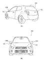
- FIG. 10 is a diagram showing a state in which the camera device 10 is attached to the automobile AM as the in-vehicle camera VC.
- 10A is a perspective view of the automobile AM viewed from the rear side
- FIG. 10B is a front view of the automobile AM viewed from the front side.
- the camera device 10 is attached to the rear part of the vehicle AM as a back monitor camera VC using an attachment member (not shown).
- the camera apparatus 10 has an attachment member (not shown) as an around monitor camera VC on the bottom surface of the door mirror (side mirror) OM of the automobile AM. Installed using.
- foreign matter adhesion prevention is used by attaching to a camera body (20) having a photographing surface (211a) exposed to the outside and preventing foreign matter from adhering to the photographing surface (211a).
- a foreign matter adhesion preventing apparatus having the above can be obtained.
- the cover (32) and the nozzle (34) are integrally formed. More preferably, the cover (32) and the nozzle (34) are integrally formed of resin by injection molding. In that case, it is desirable that the window (346a) formed in the flow path of the nozzle (34) at the time of injection molding is closed by any one of thermal welding, resin encapsulation, and component adhesion.
- the resin is preferably made of a transparent resin. In that case, it is desirable that the outer wall surface of the transparent resin is painted with a coating material (30a) made of a material that blocks light except for the cover member (322).
- the cover member (322) is provided as a single paragraph from the surrounding resin (324). In that case, it is desirable that the cover member (322) has a curved surface shape, and it is desirable that a chamfered portion (3244a) is applied to a part of the cover member (322) which is one stage.
- the foreign matter adhesion preventing device (30) preferably has an attachment member (36) for attaching the foreign matter adhesion preventing device (30) to the camera body (20).
- the cover (32) may include a peripheral portion (324) provided around the cover member (322) and attached to the camera body (20).
- the foreign matter adhesion preventing device (30) further includes an O-ring (38) mounted between the inner wall of the peripheral portion (324) of the cover (32) and the outer wall of the camera body (20).
- the camera body (20) includes a supply pipe (26) having a supply port for supplying fluid to the nozzle (34), and the nozzle (34) has an introduction port (342a) through which fluid is introduced.
- An inlet tube (342) may be included.
- the foreign matter adhesion preventing device (30) further includes a gasket (37) attached between the introduction port (342a) of the introduction tube (342) and the supply port of the supply tube (26).
- the cover member (322) preferably has an antireflection film (322a) formed on the inner surface facing the imaging surface (211a).
- the nozzle output diameter (Dno) at the tip of the nozzle (34) is preferably reduced.
- the outer surface (322b) of the cover member (322) is subjected to water repellent finish.
- the fluid is preferably composed of air.
- a camera device (10) having the foreign matter adhesion prevention device (30) and a camera body (20) to which the foreign matter adhesion prevention device (30) is attached Is obtained.
- the cover 32 and the nozzle 34 are integrally formed, but the cover 32 and the nozzle 34 may be formed separately.
- the cover 32 and the nozzle 34 are integrally formed of resin by injection molding, but it goes without saying that the manufacturing method is not limited thereto.
- the transparent resin is used as the resin.
- the entire foreign material adhesion preventing apparatus 30 may not necessarily be formed of a single type of transparent resin.
- the cover member (cover film) 322 may be formed of a transparent resin, and the other portions may be formed of an opaque resin.
- the nozzle 34 includes the three injection holes 344a, but the number of injection holes is not limited to this.
- the injection hole 344a may be only one, may be two, or may be four or more.
- the camera device according to the present invention is not limited to a vehicle-mounted camera, and may be used as a camera used in other fields (for example, a monitoring (security) field that requires monitoring outdoors).
Abstract
A foreign material adhesion preventing device (30), which is to be used by being mounted on a camera main body (20) having a photographing surface (211a) exposed to the outside, and which prevents a foreign material from adhering to the photographing surface (211a) has: a cover (32) having a cover member (322) covering the photographing surface (211a); and a nozzle (34) that sprays a fluid toward an outer surface (322b) of the cover member (322). Consequently, the highly versatile foreign material adhesion preventing device (30) capable of preventing a foreign material from directly adhering to the photographing surface (211a) of the camera main body (20) can be provided.
Description
本発明は異物付着防止装置に関し、特に、車両の外装部に取り付けられる車載カメラ等のカメラ装置(カメラ本体)のレンズ部(撮影面)に、雨滴、砂塵、泥などの異物が付着するのを防止するための装置に関する。
The present invention relates to a foreign matter adhesion preventing device, and in particular, foreign matter such as raindrops, dust, and mud adheres to a lens portion (photographing surface) of a camera device (camera body) such as an in-vehicle camera attached to an exterior portion of a vehicle. It relates to a device for preventing.
バックモニタ用カメラである車載カメラは、例えば、車体のスポイラーの下部や、ナンバープレート周囲の凹部、バックドアの上部や平坦なバックドア表面等に設置される。また、例えば、アラウンドモニタ用カメラである車載カメラは、車体のドアミラー(サイドミラー)の底面にも取り付けられる。このような車載カメラは、車体の外部に設置されるので、防塵・防水性を保つことが必要となる。
The in-vehicle camera, which is a back monitor camera, is installed on, for example, a lower part of a body spoiler, a recess around a license plate, an upper part of a back door or a flat back door surface. In addition, for example, an in-vehicle camera that is an around monitor camera is also attached to the bottom surface of a door mirror (side mirror) of a vehicle body. Since such a vehicle-mounted camera is installed outside the vehicle body, it is necessary to keep dustproof and waterproof.
特に、車載カメラのレンズ部(撮影面)には、雨滴や、砂塵、泥などの異物が付着してしまうことが度々ある。そこで、従来から、車載カメラのレンズ部(撮影面)に、洗浄液等の液体のような流体を吹き付けて異物を除去することが行われている。
Especially, the lens part (photographing surface) of the in-vehicle camera often has foreign matters such as raindrops, dust and mud. Therefore, conventionally, a foreign substance is removed by spraying a fluid such as a liquid such as a cleaning liquid onto a lens portion (photographing surface) of an in-vehicle camera.
例えば、特許文献1は、ハウジング及び該ハウジングに設けられたレンズ(撮影面の撮影窓部)を有するカメラ本体と、レンズ(撮影面の撮影窓部)に向けて洗浄液を供給するカメラ用ノズルとを備えた「ウォッシャノズル付き車載カメラ」を開示している。
For example, Patent Document 1 discloses a camera body having a housing and a lens (photographing window portion of the photographing surface) provided in the housing, and a camera nozzle that supplies a cleaning liquid toward the lens (photographing window portion of the photographing surface). "In-vehicle camera with washer nozzle" is disclosed.
上述した特許文献1には、次に述べるような問題がある。
The above-mentioned Patent Document 1 has the following problems.
特許文献1に開示されたウォッシャノズル付き車載カメラでは、カメラ本体の外形形状に合わせて、カメラ用ノズルの形状を設計しなければならない。特に、ノズルの吐出部(吐出口)の位置(角度)を、洗浄液等の液体がカメラ本体の撮影面の撮影窓部へ向けて適切に供給されるように、調整する必要がある。換言すれば、特許文献1に開示されたウォッシャノズル付き車載カメラは、汎用性に欠けるという問題がある。
In the in-vehicle camera with a washer nozzle disclosed in Patent Document 1, the shape of the camera nozzle must be designed in accordance with the outer shape of the camera body. In particular, it is necessary to adjust the position (angle) of the discharge portion (discharge port) of the nozzle so that a liquid such as a cleaning liquid is appropriately supplied toward the photographing window portion of the photographing surface of the camera body. In other words, the vehicle-mounted camera with a washer nozzle disclosed in Patent Document 1 has a problem that it lacks versatility.
また、特許文献1に開示されたウォッシャノズル付き車載カメラでは、外部に露出しているカメラ本体の撮影面の撮影窓部へ向けて、直接、洗浄液等の液体を吐出している。その為、液体の吐出後、カメラ本体の撮影面(撮影窓部)は、液体で濡れた状態となる。その結果、特許文献1に開示された車載カメラには、その濡れている撮影面(撮影窓部)に、ごみなどが再付着してしまうという問題もある。この問題を解決するためには、連続して液体を吐出し続けるか、或いは短い間隔を空けて常に液体を吐出する必要がある。しかしながら、それでは、洗浄液を頻繁に補充しなければならなくなるという、新たな問題が発生する。
Further, in the in-vehicle camera with a washer nozzle disclosed in Patent Document 1, a liquid such as a cleaning liquid is directly discharged toward the photographing window portion of the photographing surface of the camera body exposed to the outside. Therefore, after the liquid is discharged, the imaging surface (imaging window portion) of the camera body is wet with the liquid. As a result, the vehicle-mounted camera disclosed in Patent Document 1 also has a problem that dust or the like reattaches to the wet imaging surface (imaging window portion). In order to solve this problem, it is necessary to continuously discharge the liquid or to always discharge the liquid at a short interval. However, this causes a new problem that the cleaning liquid must be replenished frequently.
したがって、本発明の目的は、カメラ本体の撮影面に、直接、異物が付着することを防止できる、汎用性の高い異物付着防止装置およびそれを備えたカメラ装置を提供することにある。
Therefore, an object of the present invention is to provide a highly versatile foreign matter adhesion preventing apparatus capable of preventing foreign matter from directly adhering to the photographing surface of the camera body and a camera device equipped with the same.
本発明の他の目的は、説明が進むにつれて明らかになるだろう。
Other objects of the present invention will become clear as the description proceeds.
尚、本発明の説明で示される上方、上端、上部、上面の文言は、本発明のカメラ装置(カメラ本体)における光軸O方向の被写体側を示し、下方、下端、下部、下面の文言は、本発明のカメラ装置(カメラ本体)における光軸O方向の撮像素子側を示すものである。
In the description of the present invention, the terms “upper”, “upper”, “upper” and “upper” indicate the subject side in the direction of the optical axis O in the camera apparatus (camera body) of the present invention. 2 shows the image sensor side in the optical axis O direction in the camera device (camera body) of the present invention.
本発明の例示的な態様の要点について述べると、異物付着防止装置は、外部に露出した撮影面を有するカメラ本体に装着して用いられ、撮影面への異物の付着を防止する装置である。異物付着防止装置は、撮影面を覆うカバー部材を持つカバーと、カバー部材の外面に向けて流体を吹き付けるノズルと、を有する。
The gist of the exemplary embodiment of the present invention will be described. The foreign matter adhesion prevention device is used by being attached to a camera body having a photographing surface exposed to the outside, and prevents foreign matter from adhering to the photographing surface. The foreign matter adhesion preventing apparatus includes a cover having a cover member that covers the imaging surface, and a nozzle that sprays fluid toward the outer surface of the cover member.
本発明の他の例示的な態様によれば、上記異物付着防止装置と、該異物付着防止装置が装着されたカメラ本体と、を有する、カメラ装置が得られる。
According to another exemplary aspect of the present invention, there is obtained a camera device having the foreign matter adhesion preventing device and a camera body to which the foreign matter adhesion preventing device is attached.
本発明では、カメラ本体の撮影面に、直接、異物が付着することを防止できる、汎用性の高い異物付着防止装置およびそれを備えたカメラ装置を提供することができる。
According to the present invention, it is possible to provide a highly versatile foreign matter adhesion preventing apparatus capable of preventing foreign matter from directly adhering to the photographing surface of the camera body and a camera device including the same.
図1乃至図9を参照して、本発明の一実施形態に係るカメラ装置10およびそれに装着される異物付着防止装置30の構造について説明する。図示のカメラ装置10は、後述するように、車体後部にバックモニタ用カメラとして使用される車載カメラから成る。なお、カメラ装置10は、車体のドアミラー(サイドミラー)の底面に取り付けられる、アラウンドモニタ用カメラとして使用される車載カメラであってもよい。
With reference to FIG. 1 thru | or FIG. 9, the structure of the camera apparatus 10 which concerns on one Embodiment of this invention, and the foreign material adhesion prevention apparatus 30 with which it is mounted | worn is demonstrated. As shown later, the illustrated camera device 10 includes an in-vehicle camera used as a back monitor camera at the rear of the vehicle body. The camera device 10 may be an in-vehicle camera used as an around monitor camera attached to the bottom surface of a door mirror (side mirror) of the vehicle body.
図1はカメラ装置10の分解斜視図である。図2はカメラ装置10の外観斜視図である。図3はカメラ装置10の正面図である。図4はカメラ装置10の平面図である。図5はカメラ装置10の右側面図である。図6はカメラ装置10の底面図である。
FIG. 1 is an exploded perspective view of the camera apparatus 10. FIG. 2 is an external perspective view of the camera apparatus 10. FIG. 3 is a front view of the camera apparatus 10. FIG. 4 is a plan view of the camera device 10. FIG. 5 is a right side view of the camera apparatus 10. FIG. 6 is a bottom view of the camera apparatus 10.
また、図7は異物付着防止装置30を底面側から見た斜視図であり、図8はその異物付着防止装置30の分解斜視図である。図9は図1の線IX-IXについて断面図である。
FIG. 7 is a perspective view of the foreign matter adhesion preventing apparatus 30 as viewed from the bottom surface side, and FIG. 8 is an exploded perspective view of the foreign matter adhesion preventing apparatus 30. 9 is a cross-sectional view taken along line IX-IX in FIG.
ここでは、図1乃至図9に示されるように、直交座標系(X,Y,Z)を使用している。図1乃至図9に図示した状態では、直交座標系(X,Y,Z)において、X軸方向は前後方向(奥行方向)であり、Y軸方向は左右方向(幅方向)であり、Z軸方向は上下方向(高さ方向)である。そして、図1乃至図9に示す例においては、上下方向Zがレンズの光軸O方向である。図示の例では、上下方向Zの上方向は被写体(図示せず)が存在する方向である。尚、本実施形態において、Y軸方向(左右方向)は第1の方向とも呼ばれ、X軸方向(前後方向)は第2の方向とも呼ばれる。
Here, as shown in FIGS. 1 to 9, an orthogonal coordinate system (X, Y, Z) is used. 1 to 9, in the orthogonal coordinate system (X, Y, Z), the X-axis direction is the front-rear direction (depth direction), the Y-axis direction is the left-right direction (width direction), and Z The axial direction is the vertical direction (height direction). In the examples shown in FIGS. 1 to 9, the vertical direction Z is the direction of the optical axis O of the lens. In the illustrated example, the upward direction of the vertical direction Z is a direction in which a subject (not shown) exists. In the present embodiment, the Y-axis direction (left-right direction) is also called a first direction, and the X-axis direction (front-rear direction) is also called a second direction.
図示のカメラ装置10は、図1に示されるように、おおきく2つの構成要素から成る。すなわち、カメラ装置10は、カメラ本体20と、異物付着防止装置30とから成る。
As shown in FIG. 1, the illustrated camera device 10 is composed of two components. That is, the camera device 10 includes a camera body 20 and a foreign matter adhesion preventing device 30.
最初に、図1を参照して、カメラ本体20の構成について説明する。カメラ本体20は、レンズ群21と、このレンズ群21を保持する保持部材22と、この保持部材22の上端部に設けられたリテーナ23と、保持部材22の下端部に設けられた封止部材24と、この封止部材24から外部へ延出するケーブル25とを有する。ここで、「封止」とは、開口を閉鎖することをいう。
First, the configuration of the camera body 20 will be described with reference to FIG. The camera body 20 includes a lens group 21, a holding member 22 that holds the lens group 21, a retainer 23 provided at the upper end of the holding member 22, and a sealing member provided at the lower end of the holding member 22. 24 and a cable 25 extending from the sealing member 24 to the outside. Here, “sealing” means closing the opening.
レンズ群21は複数のレンズから成る。図1では、レンズ群21を構成する複数のレンズのうち、一番上側の上部レンズ211のみを図示している。図示のレンズ群21において、複数のレンズの各々は、円形の外形形状を持つ。
The lens group 21 is composed of a plurality of lenses. In FIG. 1, only the uppermost upper lens 211 among the plurality of lenses constituting the lens group 21 is illustrated. In the illustrated lens group 21, each of the plurality of lenses has a circular outer shape.
保持部材22は、上下方向Zに延在する実質的に四角筒形状をしている。保持部材22は、その内部空間が、レンズ群21を収容するレンズ収容空間と、基板ユニット(図示せず)を収容する基板収容空間とに分けられている。保持部材22は、その上端部に、リテーナ23を受けるためのリテーナ受け面(図示せず)を持つ。
The holding member 22 has a substantially rectangular tube shape extending in the vertical direction Z. The holding member 22 has an internal space divided into a lens housing space for housing the lens group 21 and a substrate housing space for housing a substrate unit (not shown). The holding member 22 has a retainer receiving surface (not shown) for receiving the retainer 23 at its upper end.
リテーナ23は、保持部材22の内部に水が浸入するのを防止するための部材である。リテーナ23は、保持部材22の上端に取り付けられる。リテーナ23は、上下方向Zに延在する実質的に四角筒状の外筒部232と、この外筒部232の上端で外筒部232から斜め上方にかつ内側へ突出するように設けられた、曲面リング形状の上端部234と、から成る。上端部234は、上記レンズ群21の外形形状に合致した、実質的に円形の開口(図示せず)を持つ。
The retainer 23 is a member for preventing water from entering the holding member 22. The retainer 23 is attached to the upper end of the holding member 22. The retainer 23 is provided so as to protrude substantially upward and inward from the outer cylinder part 232 at the upper end of the outer cylinder part 232 at a substantially square cylindrical outer cylinder part 232 extending in the vertical direction Z. And an upper end portion 234 having a curved ring shape. The upper end 234 has a substantially circular opening (not shown) that matches the outer shape of the lens group 21.
リテーナ23の外筒部232は、保持部材22のリテーナ受け面で受け止められる。レンズ群21の一番上側の上部レンズ211の上面211aは、リテーナ23の上端部234の開口から露出している。すなわち、リテーナ23は、上部レンズ211の上面211aを露出させた状態で、上部レンズ211の外周縁を囲むように、保持部材22の上端部に取り付けられている。
The outer cylinder part 232 of the retainer 23 is received by the retainer receiving surface of the holding member 22. The upper surface 211a of the uppermost upper lens 211 of the lens group 21 is exposed from the opening of the upper end portion 234 of the retainer 23. That is, the retainer 23 is attached to the upper end portion of the holding member 22 so as to surround the outer peripheral edge of the upper lens 211 with the upper surface 211a of the upper lens 211 exposed.
したがって、図示のカメラ本体20は、上部レンズ211の上面211aを、外部に露出した撮影面として有する。
Therefore, the illustrated camera body 20 has the upper surface 211a of the upper lens 211 as a photographing surface exposed to the outside.
尚、本実施形態では、外部に露出した撮影面が上部レンズ211の上面211aから成るが、本発明はこれに限定されない。例えば、外部に露出した撮影面は、上記特許文献1のような撮影窓部であってもよい。
In the present embodiment, the imaging surface exposed to the outside includes the upper surface 211a of the upper lens 211, but the present invention is not limited to this. For example, the photographing surface exposed to the outside may be a photographing window portion as described in Patent Document 1.
図示はしないが、基板ユニットは、センサ基板と電源基板とを含む。センサ基板上に撮像素子が搭載されている。撮像素子は、上記レンズ群21により結像された被写体像を撮像して電気信号に変換する。撮像素子は、例えば、CCD(charge coupled device)型イメージセンサや、CMOS(complementary metal oxide semiconductor)型イメージセンサ等から成る。センサ基板と電源基板とは、基板間コネクタを介して嵌合されている。電源基板に、上記ケーブル25の先端部がはんだなどにより電気的に接続されている。
Although not shown, the substrate unit includes a sensor substrate and a power supply substrate. An image sensor is mounted on the sensor substrate. The imaging device captures the subject image formed by the lens group 21 and converts it into an electrical signal. The image pickup device includes, for example, a charge coupled device (CCD) image sensor, a complementary metal oxide semiconductor (CMOS) image sensor, and the like. The sensor board and the power supply board are fitted via an inter-board connector. The tip of the cable 25 is electrically connected to the power supply board by solder or the like.
以上の説明から明らかなように、図示のカメラ本体20は、実質的に四角柱の外形形状をしている。ここで、一般に市販されている車載カメラのようなカメラ装置は、図1に示されるカメラ本体20の外形形状のように、実質的に四角柱の外形形状をしていることに注意されたい。すなわち、一般に市販されているカメラ装置は、その高さ寸法が異なる場合があるが、実質的に同じ縦寸法および横寸法を有していることに注意されたい。
As apparent from the above description, the illustrated camera body 20 has a substantially quadrangular prism shape. Here, it should be noted that a camera device such as an on-vehicle camera that is generally commercially available has a substantially quadrangular prism outer shape like the outer shape of the camera body 20 shown in FIG. That is, it should be noted that generally commercially available camera devices may have substantially the same vertical and horizontal dimensions, although their height may vary.
保持部材22と、リテーナ23と、封止部材24との組み合わせは、カメラ本体20のハウジングとして働く。
The combination of the holding member 22, the retainer 23, and the sealing member 24 serves as a housing for the camera body 20.
図5に示されるように、カメラ本体20は、後述する異物付着防止装置30のノズル34へ、流体を供給するための供給口を持つ供給管26を更に有する。図示の例では、供給管26は、保持部材22の背面で上下方向Zに延在して設けられている。供給管26は、左右方向(第1の方向)Yに幅広い矩形管から成る。図示の例では、流体は空気から成る。
As shown in FIG. 5, the camera body 20 further includes a supply pipe 26 having a supply port for supplying a fluid to a nozzle 34 of a foreign matter adhesion prevention device 30 described later. In the illustrated example, the supply pipe 26 extends in the up-down direction Z on the back surface of the holding member 22. The supply pipe 26 is a rectangular pipe that is wide in the left-right direction (first direction) Y. In the example shown, the fluid consists of air.
供給管26の下端部には、略円筒状の差込部28が突出するように設けられている。差込部28には、図示しないホースの一端が差し込まれる。ホースの他端には、図示しないポンプのような空気供給源が接続されている。尚、流体は、空気に限定されず、洗浄液等の液体であってもよい。
A substantially cylindrical insertion portion 28 is provided at the lower end portion of the supply pipe 26 so as to protrude. One end of a hose (not shown) is inserted into the insertion portion 28. An air supply source such as a pump (not shown) is connected to the other end of the hose. The fluid is not limited to air and may be a liquid such as a cleaning liquid.
また、図1に示されるように、カメラ本体20は、保持部材22の左右方向(第1の方向)Yの両側面に、リテーナ23に近接した位置で外側へ突出する一対の突起部(凸部)27(但し、図1では、右側の突起部のみ図示する)を有する。この一対の突起部27には、図2および図3に示されるように、後述する異物付着防止装置30の一対の留め具36の孔(凹部)36aが嵌めこまれる。したがって、カメラ本体20の一対の突起部27と、異物付着防止装置30の留め具36との組み合わせは、スナップフィットとして働く。このような構成を採用することにより、異物付着防止装置30をカメラ本体20に容易に取り付けることができる。換言すれば、異物付着防止装置30のカメラ本体20への取付け作業を向上させることができる。
Further, as shown in FIG. 1, the camera body 20 has a pair of protrusions (protrusions) protruding outward at positions close to the retainer 23 on both side surfaces of the holding member 22 in the left-right direction (first direction) Y. Part) 27 (however, in FIG. 1, only the right protrusion is shown). As shown in FIGS. 2 and 3, holes (concave portions) 36 a of a pair of fasteners 36 of the foreign matter adhesion preventing device 30 described later are fitted into the pair of protrusions 27. Therefore, the combination of the pair of protrusions 27 of the camera body 20 and the fastener 36 of the foreign matter adhesion preventing device 30 functions as a snap fit. By adopting such a configuration, the foreign matter adhesion preventing device 30 can be easily attached to the camera body 20. In other words, the work of attaching the foreign matter adhesion preventing device 30 to the camera body 20 can be improved.
なお、図示の実施形態では、スナップフィットを、カメラ本体20側に凸部27を設け、異物付着防止装置30側に凹部36aを設けて構成しているが、逆であってもよい。即ち、スナップフィットを、カメラ本体20側に凹部を設け、異物付着防止装置30側に凸部を設けて構成してもよい。
In the illustrated embodiment, the snap fit is configured by providing the convex portion 27 on the camera body 20 side and the concave portion 36a on the foreign matter adhesion preventing device 30 side, but the reverse may be possible. That is, the snap fit may be configured by providing a concave portion on the camera body 20 side and providing a convex portion on the foreign matter adhesion preventing device 30 side.
このように、異物付着防止装置30の留め具36は、当該異物付着防止装置30をカメラ本体20へ取り付けるための取付け部材として働く。
Thus, the fastener 36 of the foreign matter adhesion preventing device 30 serves as an attachment member for attaching the foreign matter adhesion preventing device 30 to the camera body 20.
次に、図1乃至図9を参照して、カメラ本体20に装着される異物付着防止装置30について説明する。
Next, with reference to FIGS. 1 to 9, the foreign matter adhesion preventing device 30 attached to the camera body 20 will be described.
異物付着防止装置30は、外部に露出した撮影面211aを有するカメラ本体20に装着して用いられる。異物付着防止装置30は、撮影面211aへ異物が付着するのを防止するための装置である。ここで、異物は、例えば、雨滴、虫、砂塵、泥等から成る。
The foreign matter adhesion preventing device 30 is used by being mounted on the camera body 20 having the photographing surface 211a exposed to the outside. The foreign matter adhesion preventing device 30 is a device for preventing foreign matter from adhering to the imaging surface 211a. Here, the foreign matter is composed of, for example, raindrops, insects, sand dust, mud and the like.
異物付着防止装置30は、撮影面211aを覆うカバー部材322を持つカバー32と、カバー部材322の外面322bに向けて流体を吹き付けるノズル34と、を有する。前述したように、図示の例では、流体は空気から成る。ここで、カバー部材322の外面322bへ空気を連続的に吹き付けても良いし、或いは、車内に設置されたスイッチ(図示せず)を押したときに所定時間だけ、カバー部材322の外面322bへ空気を連続的に吹き付けるようにしても良い。
The foreign matter adhesion preventing apparatus 30 includes a cover 32 having a cover member 322 that covers the imaging surface 211a, and a nozzle 34 that sprays fluid toward the outer surface 322b of the cover member 322. As described above, in the illustrated example, the fluid consists of air. Here, air may be continuously blown to the outer surface 322b of the cover member 322, or when a switch (not shown) installed in the vehicle is pressed, the air is directed to the outer surface 322b of the cover member 322 only for a predetermined time. Air may be blown continuously.
図示のカバー部材322は、図4に示されるように、平面視、円形形状をしており、薄い膜状に形成されている。したがって、カバー部材322は、カバー膜とも呼ばれる。カバー部材322の直径は、カメラ本体20の上部レンズ211(撮影面211a)の直径より大きい。
As shown in FIG. 4, the illustrated cover member 322 has a circular shape in plan view, and is formed in a thin film shape. Therefore, the cover member 322 is also called a cover film. The diameter of the cover member 322 is larger than the diameter of the upper lens 211 (photographing surface 211a) of the camera body 20.
カバー32は、カバー部材322の半径方向外側に設けられた周辺部324を有する。周辺部324は、四角筒状の装着部3242と、上端保持部3244とから成る。四角筒状の装着部3242は、図7に示されるように、カメラ本体20の保持部材22の外形形状(寸法)と実質的に等しい寸法の略矩形開口3242aを持ち、カメラ本体20の保持部材22に装着される。上端保持部3244は、この装着部3242とカバー部材322との間に設けられ、カバー部材〈カバー膜〉322を保持する。
The cover 32 has a peripheral portion 324 provided outside the cover member 322 in the radial direction. The peripheral portion 324 includes a square cylindrical mounting portion 3242 and an upper end holding portion 3244. As shown in FIG. 7, the rectangular cylindrical mounting portion 3242 has a substantially rectangular opening 3242 a having a dimension substantially equal to the outer shape (dimension) of the holding member 22 of the camera body 20, and the holding member of the camera body 20. 22 is attached. The upper end holding portion 3244 is provided between the mounting portion 3242 and the cover member 322 and holds the cover member <cover film> 322.
一方、ノズル34は、図8および図9に示されるように、供給管26の供給口と実質的に同じ開口形状の導入口342aを持つ導入管342と、導入管342の先端部に設けられた吐出部344とを有する。導入管342は、カメラ本体20の保持部材22の背面側で、上下方向Zに延在した矩形管から成る。一方、吐出部344は、導入管342の流路と連通して、前後方向Xに延在する3本の噴射孔344a(図1参照)を持つ。
On the other hand, as shown in FIGS. 8 and 9, the nozzle 34 is provided at an introduction pipe 342 having an introduction port 342 a having substantially the same opening shape as the supply port of the supply pipe 26, and a distal end portion of the introduction pipe 342. A discharge portion 344. The introduction pipe 342 is a rectangular pipe extending in the up-down direction Z on the back side of the holding member 22 of the camera body 20. On the other hand, the discharge portion 344 has three injection holes 344 a (see FIG. 1) that communicate with the flow path of the introduction pipe 342 and extend in the front-rear direction X.
異物付着防止装置30は、図5、図7および図8に示されるように、導入管342の導入口342aと、供給管26の供給口との間に取り付けられたガスケット37を備える。ガスケット37は、例えば、両面テープ等を使用して、導入口342aおよび供給口に取り付けられる。これにより、導入管342と供給管26との間の気密性を確保している。
As shown in FIGS. 5, 7, and 8, the foreign matter adhesion preventing device 30 includes a gasket 37 attached between the introduction port 342 a of the introduction tube 342 and the supply port of the supply tube 26. The gasket 37 is attached to the introduction port 342a and the supply port using, for example, a double-sided tape. Thereby, the airtightness between the introduction pipe 342 and the supply pipe 26 is ensured.
本例の異物付着防止装置30では、カバー32とノズル34と一対の留め具36とが一体に構成されている。具体的には、カバー32とノズル34と一対の留め具36とが、射出成形によって樹脂で一体に形成されている。
In the foreign matter adhesion preventing apparatus 30 of this example, the cover 32, the nozzle 34, and the pair of fasteners 36 are integrally configured. Specifically, the cover 32, the nozzle 34, and the pair of fasteners 36 are integrally formed of resin by injection molding.
図9に示されるように、射出成形の際に、ノズル34の流路(本例の場合、吐出部344の3本の噴射孔344aと導入管342との間を接続する流路)に3つの窓346a(但し、図9では、1つの窓346aのみ図示している)が形成される。そして、射出成形の際に、これら3つの窓346aに近接して、3つの樹脂片346も形成される。そこで、本例の異物付着防止装置30では、3つの樹脂片346を熱溶着して、3つの窓346aを塞いでいる。
As shown in FIG. 9, at the time of injection molding, 3 in the flow path of the nozzle 34 (in this example, the flow path connecting between the three injection holes 344a of the discharge portion 344 and the introduction pipe 342). Two windows 346a (however, only one window 346a is shown in FIG. 9) are formed. In the injection molding, three resin pieces 346 are also formed in the vicinity of these three windows 346a. Therefore, in the foreign matter adhesion preventing apparatus 30 of this example, the three resin pieces 346 are thermally welded to close the three windows 346a.
尚、本例の異物付着防止装置30では、3つの窓346aを熱溶着で塞いでいるが、それ以外の方法で塞いでもよい。例えば、上記3つの樹脂片346を形成せずに、3つの窓346aに樹脂を封入して塞いでも良いし、3つの窓346aに3つの樹脂製部品のような部品を挿入した後に接着して塞いでもよい。
In addition, in the foreign material adhesion preventing apparatus 30 of this example, the three windows 346a are closed by thermal welding, but may be closed by other methods. For example, the three resin pieces 346 may not be formed, and the three windows 346a may be sealed with resin, or may be bonded after inserting three resin parts into the three windows 346a. It may be closed.
また、本例の異物付着防止装置30では、異物付着防止装置30を構成する樹脂は、透明樹脂から成る。そのような透明樹脂としては、例えば、アクリル樹脂や、ポリカーボネート樹脂などを使用することができる。
In the foreign matter adhesion preventing apparatus 30 of this example, the resin constituting the foreign matter adhesion preventing apparatus 30 is made of a transparent resin. As such a transparent resin, for example, an acrylic resin or a polycarbonate resin can be used.
さらに、本例の異物付着防止装置30では、カバー部材322を除いて、異物付着防止装置30を構成する透明樹脂の外壁面を、光を遮断する材料から成る塗装材料30aで塗装している。これにより、カバー部材322以外から、光がカメラ本体20の撮影面211aに入射するのを防止することができる。その結果、カメラ本体20の撮像素子で撮像された画像におけるゴーストやフレアを防止することができる。また、本例の異物付着防止装置30では、カバー部材322には、カメラ本体20の撮影面211aと対向する内面に反射防止膜322aが形成されている。これによっても、カメラ本体20の撮像素子で撮像された画像におけるゴーストやフレアを防止することができる。
Further, in the foreign matter adhesion preventing apparatus 30 of this example, the outer wall surface of the transparent resin constituting the foreign matter adhesion preventing apparatus 30 is coated with a coating material 30a made of a material that blocks light, except for the cover member 322. Thereby, it is possible to prevent light from entering the imaging surface 211 a of the camera body 20 from other than the cover member 322. As a result, it is possible to prevent ghosts and flares in an image captured by the image sensor of the camera body 20. In the foreign matter adhesion preventing apparatus 30 of this example, the cover member 322 has an antireflection film 322a formed on the inner surface of the camera body 20 facing the imaging surface 211a. Also by this, it is possible to prevent ghosts and flares in an image captured by the image sensor of the camera body 20.
図9に示されるように、カバー部材322は、その周辺の上端保持部3244より一段落として設けられている。これにより、カバー部材322の外面322bに、虫、砂塵、泥などが付着するのを防止することができる。
As shown in FIG. 9, the cover member 322 is provided as a single paragraph from the upper end holding portion 3244 in the vicinity thereof. Thereby, it is possible to prevent insects, dust, mud, and the like from adhering to the outer surface 322b of the cover member 322.
また、図9に示されるように、図示のカバー部材322は、外側へ突出した曲面形状をしている。これにより、カメラ本体20の視野(FOV:field of view)又は画角(AOV:angle of view)を確保している。さらに、本例の異物付着防止装置30では、図9に示されるように、カバー部材322の一段落とした部分に面取り部3244aが施されている。これによっても、カメラ本体20の視野又は画角を確保している。
Further, as shown in FIG. 9, the illustrated cover member 322 has a curved shape protruding outward. Thus, the field of view (FOV: field of view) or the angle of view (AOV: angle of view) of the camera body 20 is secured. Further, in the foreign matter adhesion preventing apparatus 30 of the present example, as shown in FIG. 9, a chamfered portion 3244 a is applied to a part of the cover member 322 that is one stage. This also secures the field of view or the angle of view of the camera body 20.
図7および図8に示されるように、異物付着防止装置30は、カバー32の周辺部324の内壁とカメラ本体20の外壁との間に装着されるOリング38を更に有する。これにより、カメラ本体20と異物付着防止装置30のカバー32との間の空間(隙間)を密閉することができる。その結果、カメラ本体20とカバー32との間の隙間に、水分が浸入するのを防止することができる。
7 and 8, the foreign matter adhesion preventing device 30 further includes an O-ring 38 that is mounted between the inner wall of the peripheral portion 324 of the cover 32 and the outer wall of the camera body 20. Thereby, the space (gap) between the camera body 20 and the cover 32 of the foreign matter adhesion preventing apparatus 30 can be sealed. As a result, it is possible to prevent moisture from entering the gap between the camera body 20 and the cover 32.
また、本例の異物付着防止装置30では、図9に示されるように、ノズル34の先端(すなわち、吐出部344の3本の噴射孔344aの先端)のノズル出力径Dnoが絞られている。このような構造を採用することにより、噴射孔344aからカメラ本体20の撮影面211aへ向けて噴射する、空気の流速を増大することができるという効果を奏する。
Further, in the foreign matter adhesion preventing apparatus 30 of this example, as shown in FIG. 9, the nozzle output diameter Dno at the tip of the nozzle 34 (that is, the tip of the three injection holes 344 a of the discharge unit 344) is reduced. . By adopting such a structure, there is an effect that it is possible to increase the flow velocity of air that is injected from the injection hole 344a toward the imaging surface 211a of the camera body 20.
この構造により、カバー部材322の外面322bに対する噴射孔344aの先端の角度が浅いことから、噴射された流体はカバー部材322の外面322bの表面形状に沿って進行するコアンダ効果により、噴射孔344aの反対側に位置する面取り部3244aまで離間することなく到達する。換言すれば、噴射孔344aを出た流体はカバー部材322の外面322bから消散してしまう離間成分が少なく、流体の大部分が異物除去に寄与するため、異物の除去効率が高い。
With this structure, the angle of the tip of the injection hole 344a with respect to the outer surface 322b of the cover member 322 is shallow. The chamfered portion 3244a located on the opposite side is reached without being separated. In other words, the fluid exiting the injection hole 344a has a small separation component that dissipates from the outer surface 322b of the cover member 322, and most of the fluid contributes to the removal of foreign matter, so the foreign matter removal efficiency is high.
さらに、本例の異物付着防止装置30では、カバー部材322の外面322bには、撥水加工が施されている。これにより、カバー部材322の外面322bに付着するかも知れない雨滴を効率的にはじくことが可能となる。
Furthermore, in the foreign matter adhesion preventing apparatus 30 of this example, the outer surface 322b of the cover member 322 is subjected to water repellent finishing. This makes it possible to efficiently repel raindrops that may adhere to the outer surface 322b of the cover member 322.
以上の説明から明らかなように、本発明の実施形態によれば、異物付着防止装置30は、カメラ本体20の撮影面211aを覆うカバー32を備えているので、撮影面211aに、直接、異物が付着するのを防止することが可能となる。また、異物付着防止装置30は、市販のカメラ装置に容易に装着することが可能な構成をしているので、汎用性を向上させることができる。また、流体として空気を使用した場合、流体として洗浄液のような液体を使用した場合と比較して、液体を補充するというような手間を省いたり、ごみが再付着するのを防ぐことが可能となる。
As is clear from the above description, according to the embodiment of the present invention, the foreign matter adhesion preventing apparatus 30 includes the cover 32 that covers the imaging surface 211a of the camera body 20, and thus the foreign matter directly on the imaging surface 211a. Can be prevented from adhering. Moreover, since the foreign material adhesion preventing device 30 has a configuration that can be easily attached to a commercially available camera device, versatility can be improved. In addition, when air is used as the fluid, it is possible to save the trouble of replenishing the liquid and prevent the dust from reattaching compared to the case where a liquid such as a cleaning liquid is used as the fluid. Become.
図10は、カメラ装置10を車載カメラVCとして自動車AMに取り付けた状態を示す図である。図10において、(A)は自動車AMを後面側から見た斜視図であり、(B)は自動車AMを前面側から見た正面図である。
FIG. 10 is a diagram showing a state in which the camera device 10 is attached to the automobile AM as the in-vehicle camera VC. 10A is a perspective view of the automobile AM viewed from the rear side, and FIG. 10B is a front view of the automobile AM viewed from the front side.
図10(A)に示されるように、カメラ装置10は、自動車AMの車体後部にバックモニタ用カメラVCとして取付け部材(図示せず)を使用して取り付けられる。
As shown in FIG. 10A, the camera device 10 is attached to the rear part of the vehicle AM as a back monitor camera VC using an attachment member (not shown).
また、図10(A)および図10(B)に示されるように、カメラ装置10は、自動車AMのドアミラー(サイドミラー)OMの底面にアラウンドモニタ用カメラVCとして取付け部材(図示せず)を使用して取り付けられる。
As shown in FIGS. 10A and 10B, the camera apparatus 10 has an attachment member (not shown) as an around monitor camera VC on the bottom surface of the door mirror (side mirror) OM of the automobile AM. Installed using.
また、図10(A)および図10(B)に示されるように、カメラ装置10が自動車AMに取り付けられ、使用されている際に、もしカバー部材322の外面322bに飛び石等の接触により傷が付いた場合、異物付着防止装置30のみを交換するだけで良く、カメラ本体20を交換する必要が無い。
Further, as shown in FIGS. 10A and 10B, when the camera apparatus 10 is attached to the automobile AM and used, the outer surface 322b of the cover member 322 is damaged by contact with a stepping stone or the like. Is attached, it is only necessary to replace the foreign matter adhesion preventing device 30 and there is no need to replace the camera body 20.
本発明の例示的な態様について説明する。
An exemplary aspect of the present invention will be described.
本発明の例示的な態様によれば、外部に露出した撮影面(211a)を有するカメラ本体(20)に装着して用いられ、撮影面(211a)への異物の付着を防止する異物付着防止装置(30)であって、撮影面(211a)を覆うカバー部材(322)を持つカバー(32)と、カバー部材(322)の外面(322b)に向けて流体を吹き付けるノズル(34)と、を有する異物付着防止装置が得られる。
According to an exemplary aspect of the present invention, foreign matter adhesion prevention is used by attaching to a camera body (20) having a photographing surface (211a) exposed to the outside and preventing foreign matter from adhering to the photographing surface (211a). A device (30), a cover (32) having a cover member (322) covering the imaging surface (211a), a nozzle (34) for spraying fluid toward the outer surface (322b) of the cover member (322), A foreign matter adhesion preventing apparatus having the above can be obtained.
上記異物付着防止装置(30)において、上記カバー(32)と上記ノズル(34)とが一体に構成されていることが好ましい。また、カバー(32)とノズル(34)とが、射出成形によって樹脂で一体に形成されていることがより好ましい。その場合、射出成形の際にノズル(34)の流路に形成される窓(346a)が、熱溶着、樹脂封入、および部品接着のいずれかで塞がれることが望ましい。樹脂は、透明樹脂から成ることが好ましい。その場合、カバー部材(322)を除いて、透明樹脂の外壁面が光を遮断する材料から成る塗装材料(30a)で塗装されていることが望ましい。また、カバー部材(322)が、その周辺の樹脂(324)より一段落として設けられていることが好ましい。その場合、カバー部材(322)は、曲面形状をしていることが望ましく、カバー部材(322)の一段落とした部分に面取り部(3244a)が施されていることが望ましい。
In the foreign matter adhesion preventing device (30), it is preferable that the cover (32) and the nozzle (34) are integrally formed. More preferably, the cover (32) and the nozzle (34) are integrally formed of resin by injection molding. In that case, it is desirable that the window (346a) formed in the flow path of the nozzle (34) at the time of injection molding is closed by any one of thermal welding, resin encapsulation, and component adhesion. The resin is preferably made of a transparent resin. In that case, it is desirable that the outer wall surface of the transparent resin is painted with a coating material (30a) made of a material that blocks light except for the cover member (322). Moreover, it is preferable that the cover member (322) is provided as a single paragraph from the surrounding resin (324). In that case, it is desirable that the cover member (322) has a curved surface shape, and it is desirable that a chamfered portion (3244a) is applied to a part of the cover member (322) which is one stage.
また、上記異物付着防止装置(30)は、当該異物付着防止装置(30)をカメラ本体(20)へ取り付けるための取付け部材(36)を有することが好ましい。また、上記カバー(32)は、カバー部材(322)の周囲に設けられてカメラ本体(20)に装着される周辺部(324)を備えてよい。この場合、異物付着防止装置(30)は、カバー(32)の周辺部(324)の内壁とカメラ本体(20)の外壁との間に装着されるOリング(38)を更に有することが望ましい。また、カメラ本体(20)は、ノズル(34)へ流体を供給するための供給口を持つ供給管(26)を備え、ノズル(34)は、流体が導入される導入口(342a)を持つ導入管(342)を有してよい。この場合、異物付着防止装置(30)は、導入管(342)の導入口(342a)と、供給管(26)の供給口との間に取り付けられたガスケット(37)を更に有することが好ましい。さらに、カバー部材(322)は、撮影面(211a)と対向する内面に反射防止膜(322a)が形成されていることが好ましい。ノズル(34)の先端のノズル出力径(Dno)が絞られていることが望ましい。さらに、カバー部材(322)の外面(322b)には、撥水加工が施されていることが好ましい。上記流体は、空気から成ることが望ましい。
The foreign matter adhesion preventing device (30) preferably has an attachment member (36) for attaching the foreign matter adhesion preventing device (30) to the camera body (20). The cover (32) may include a peripheral portion (324) provided around the cover member (322) and attached to the camera body (20). In this case, it is desirable that the foreign matter adhesion preventing device (30) further includes an O-ring (38) mounted between the inner wall of the peripheral portion (324) of the cover (32) and the outer wall of the camera body (20). . The camera body (20) includes a supply pipe (26) having a supply port for supplying fluid to the nozzle (34), and the nozzle (34) has an introduction port (342a) through which fluid is introduced. An inlet tube (342) may be included. In this case, it is preferable that the foreign matter adhesion preventing device (30) further includes a gasket (37) attached between the introduction port (342a) of the introduction tube (342) and the supply port of the supply tube (26). . Further, the cover member (322) preferably has an antireflection film (322a) formed on the inner surface facing the imaging surface (211a). The nozzle output diameter (Dno) at the tip of the nozzle (34) is preferably reduced. Furthermore, it is preferable that the outer surface (322b) of the cover member (322) is subjected to water repellent finish. The fluid is preferably composed of air.
本発明の他の例示的な態様によれば、上記異物付着防止装置(30)と、該異物付着防止装置(30)が装着されたカメラ本体(20)と、を有する、カメラ装置(10)が得られる。
According to another exemplary aspect of the present invention, a camera device (10) having the foreign matter adhesion prevention device (30) and a camera body (20) to which the foreign matter adhesion prevention device (30) is attached. Is obtained.
尚、上記括弧内の参照符号は、本発明の理解を容易にするために付したものであり、一例に過ぎず、本発明は、これらに限定されないのは勿論である。
Note that the reference numerals in the parentheses are given for easy understanding of the present invention, and are merely examples, and the present invention is of course not limited thereto.
以上、実施の形態を参照して本発明を説明したが、本発明は上記実施の形態に限定されるものではない。本発明の構成や詳細には、本発明のスコープ内で当業者が理解し得る様々な変更をすることができる。
Although the present invention has been described above with reference to the embodiment, the present invention is not limited to the above embodiment. Various changes that can be understood by those skilled in the art can be made to the configuration and details of the present invention within the scope of the present invention.
例えば、上述した実施形態に係る異物付着防止装置30では、カバー32とノズル34とを一体に構成しているが、カバー32とノズル34とを別体で構成してもよい。また、上述した実施形態に係る異物付着防止装置30では、カバー32とノズル34とを、射出成形によって樹脂で一体に形成しているが、製法はそれに限定されないのは勿論である。また、上述した実施形態に係る異物付着防止装置30では、樹脂として透明樹脂を使用しているが、必ずしも異物付着防止装置30の全部を一種類の透明樹脂で形成しなくてもよい。例えば、異物付着防止装置30のうち、カバー部材(カバー膜)322のみを透明樹脂で形成し、それ以外の部分を不透明樹脂で形成してもよい。さらに、上述した実施形態に係る異物付着防止装置30では、ノズル34が3本の噴射孔344aを備えているが、噴射孔の本数はこれに限定されない。例えば、噴射孔344aは、1本のみであってもよく、2本でもよく、4本以上あってもよい。
For example, in the foreign matter adhesion preventing apparatus 30 according to the above-described embodiment, the cover 32 and the nozzle 34 are integrally formed, but the cover 32 and the nozzle 34 may be formed separately. Moreover, in the foreign material adhesion preventing apparatus 30 according to the above-described embodiment, the cover 32 and the nozzle 34 are integrally formed of resin by injection molding, but it goes without saying that the manufacturing method is not limited thereto. Moreover, in the foreign material adhesion preventing apparatus 30 according to the above-described embodiment, the transparent resin is used as the resin. However, the entire foreign material adhesion preventing apparatus 30 may not necessarily be formed of a single type of transparent resin. For example, in the foreign matter adhesion preventing apparatus 30, only the cover member (cover film) 322 may be formed of a transparent resin, and the other portions may be formed of an opaque resin. Furthermore, in the foreign material adhesion preventing apparatus 30 according to the above-described embodiment, the nozzle 34 includes the three injection holes 344a, but the number of injection holes is not limited to this. For example, the injection hole 344a may be only one, may be two, or may be four or more.
この出願は、2015年7月7日に出願された日本出願特願2015-136223号を基礎とする優先権を主張し、その開示の全てをここに取り込む。
This application claims priority based on Japanese Patent Application No. 2015-136223 filed on July 7, 2015, the entire disclosure of which is incorporated herein.
本発明に係るカメラ装置は、車載カメラには限定されず、他の分野(例えば、野外において監視を必要とする監視(警備)分野など)に使用されるカメラとしても利用され得る。
The camera device according to the present invention is not limited to a vehicle-mounted camera, and may be used as a camera used in other fields (for example, a monitoring (security) field that requires monitoring outdoors).
10 カメラ装置(車載カメラ)
20 カメラ本体
21 レンズ群
211 上部レンズ
211a 上面(撮影面)
22 保持部材
23 リテーナ
232 外筒部
234 上端部
24 封止部材
25 ケーブル
26 供給管
27 突起部(凸部)
28 差込部
30 異物付着防止装置
30a 塗装材料
32 カバー
322 カバー部材(カバー膜)
322a 反射防止膜
322b 外面
324 周辺部
3242 装着部
3242a 略矩形開口
3244 上端保持部
3244a 面取り部
34 ノズル
342 導入管
342a 導入口
344 吐出部
344a 噴射孔
346 樹脂片
346a 窓
36 留め具(取付け部材)
36a 孔(凹部)
37 ガスケット
38 Oリング
Dno ノズル出力径
AM 自動車
OM ドアミラー(サイドミラー)
VC 車載カメラ
O 光軸
X 前後方向(第2の方向)
Y 左右方向(第1の方向)
Z 上下方向 10 Camera device (on-vehicle camera)
20Camera body 21 Lens group 211 Upper lens 211a Upper surface (imaging surface)
22 Holdingmember 23 Retainer 232 Outer cylinder part 234 Upper end part 24 Sealing member 25 Cable 26 Supply pipe 27 Projection part (convex part)
28Insertion part 30 Foreign matter adhesion prevention device 30a Coating material 32 Cover 322 Cover member (cover film)
322a Antireflection film 322b Outer surface 324 Peripheral portion 3242 Mounting portion 3242a Roughly rectangular opening 3244 Upper end holding portion 3244a Chamfered portion 34 Nozzle 342 Introducing pipe 342a Inlet port 344 Discharge portion 344a Injection hole 346 Resin piece 346a Window member Attaching member 36
36a hole (concave)
37 Gasket 38 O-ring Dno Nozzle output diameter AM Automobile OM Door mirror (side mirror)
VC In-vehicle camera
O Optical axis X Front-back direction (second direction)
Y Left-right direction (first direction)
Z Vertical direction
20 カメラ本体
21 レンズ群
211 上部レンズ
211a 上面(撮影面)
22 保持部材
23 リテーナ
232 外筒部
234 上端部
24 封止部材
25 ケーブル
26 供給管
27 突起部(凸部)
28 差込部
30 異物付着防止装置
30a 塗装材料
32 カバー
322 カバー部材(カバー膜)
322a 反射防止膜
322b 外面
324 周辺部
3242 装着部
3242a 略矩形開口
3244 上端保持部
3244a 面取り部
34 ノズル
342 導入管
342a 導入口
344 吐出部
344a 噴射孔
346 樹脂片
346a 窓
36 留め具(取付け部材)
36a 孔(凹部)
37 ガスケット
38 Oリング
Dno ノズル出力径
AM 自動車
OM ドアミラー(サイドミラー)
VC 車載カメラ
O 光軸
X 前後方向(第2の方向)
Y 左右方向(第1の方向)
Z 上下方向 10 Camera device (on-vehicle camera)
20
22 Holding
28
36a hole (concave)
37 Gasket 38 O-ring Dno Nozzle output diameter AM Automobile OM Door mirror (side mirror)
VC In-vehicle camera
O Optical axis X Front-back direction (second direction)
Y Left-right direction (first direction)
Z Vertical direction
Claims (17)
- 外部に露出した撮影面(211a)を有するカメラ本体(20)に装着して用いられ、前記撮影面(211a)への異物の付着を防止する異物付着防止装置(30)であって、
前記撮影面(211a)を覆うカバー部材(322)を持つカバー(32)と、
前記カバー部材(322)の外面(322b)に向けて流体を吹き付けるノズル(34)と、
を有する異物付着防止装置。 A foreign matter adhesion preventing device (30) used by being attached to a camera body (20) having a photographing surface (211a) exposed to the outside and preventing foreign matter from adhering to the photographing surface (211a),
A cover (32) having a cover member (322) covering the imaging surface (211a);
A nozzle (34) for spraying fluid toward the outer surface (322b) of the cover member (322);
Foreign matter adhesion prevention apparatus having - 前記カバー(32)と前記ノズル(34)とが一体に構成されている、請求項1に記載の異物付着防止装置。 The foreign matter adhesion preventing apparatus according to claim 1, wherein the cover (32) and the nozzle (34) are integrally formed.
- 前記カバー(32)と前記ノズル(34)とが、射出成形によって樹脂で一体に形成されている、請求項2に記載の異物付着防止装置。 The foreign matter adhesion preventing apparatus according to claim 2, wherein the cover (32) and the nozzle (34) are integrally formed of resin by injection molding.
- 前記射出成形の際に前記ノズル(34)の流路に形成される窓(346a)が、熱溶着、樹脂封入、および部品接着のいずれかで塞がれている、請求項3に記載の異物付着防止装置。 The foreign object according to claim 3, wherein the window (346a) formed in the flow path of the nozzle (34) during the injection molding is closed by any one of heat welding, resin encapsulation, and component adhesion. Adhesion prevention device.
- 前記樹脂が透明樹脂から成る、請求項3又は4に記載の異物付着防止装置。 The foreign matter adhesion preventing apparatus according to claim 3 or 4, wherein the resin is made of a transparent resin.
- 前記カバー部材(322)を除いて、前記透明樹脂の外壁面が光を遮断する材料から成る塗装材料(30a)で塗装されている、請求項5に記載の異物付着防止装置。 The foreign matter adhesion preventing device according to claim 5, wherein an outer wall surface of the transparent resin is coated with a coating material (30a) made of a material that blocks light except for the cover member (322).
- 前記カバー部材(322)が、その周辺の樹脂より一段落として設けられている、請求項3乃至6のいずれか1項に記載の異物付着防止装置。 The foreign matter adhesion preventing apparatus according to any one of claims 3 to 6, wherein the cover member (322) is provided as one stage from a resin around the cover member (322).
- 前記カバー部材(322)が曲面形状をしている、請求項7に記載の異物付着防止装置。 The foreign matter adhesion preventing apparatus according to claim 7, wherein the cover member (322) has a curved shape.
- 前記カバー部材(322)の一段落とした部分に面取り部(3244a)が施されている、請求項8に記載の異物付着防止装置。 The foreign matter adhesion preventing apparatus according to claim 8, wherein a chamfered portion (3244a) is provided on a part of the cover member (322).
- 前記異物付着防止装置は、当該異物付着防止装置(30)を前記カメラ本体(20)へ取り付けるための取付け部材(36)を有する、請求項1乃至9のいずれか1項に記載の異物付着防止装置。 10. The foreign matter adhesion prevention apparatus according to claim 1, wherein the foreign matter adhesion prevention device has an attachment member (36) for attaching the foreign matter adhesion prevention device (30) to the camera body (20). apparatus.
- 前記カバー(32)は、前記カバー部材(322)の周囲に設けられて前記カメラ本体(20)に装着される周辺部(324)を備え、
前記異物付着防止装置(30)は、前記カバー(32)の前記周辺部(324)の内壁と前記カメラ本体(20)の外壁との間に装着されるOリング(38)を更に有する、請求項1乃至10のいずれか1項に記載の異物付着防止装置。 The cover (32) includes a peripheral portion (324) provided around the cover member (322) and attached to the camera body (20).
The foreign matter adhesion preventing device (30) further includes an O-ring (38) attached between an inner wall of the peripheral portion (324) of the cover (32) and an outer wall of the camera body (20). Item 11. The foreign matter adhesion preventing apparatus according to any one of Items 1 to 10. - 前記カメラ本体(20)は、前記ノズル(34)へ前記流体を供給するための供給口を持つ供給管(26)を備え、
前記ノズル(34)は、前記流体が導入される導入口(342a)を持つ導入管(342)を有し、
前記異物付着防止装置(30)は、前記導入管(342)の前記導入口(342a)と、前記供給管(26)の前記供給口との間に取り付けられたガスケット(37)を更に有する、請求項1乃至11のいずれか1項に記載の異物付着防止装置。 The camera body (20) includes a supply pipe (26) having a supply port for supplying the fluid to the nozzle (34).
The nozzle (34) has an introduction pipe (342) having an introduction port (342a) through which the fluid is introduced,
The foreign matter adhesion preventing device (30) further includes a gasket (37) attached between the introduction port (342a) of the introduction pipe (342) and the supply port of the supply pipe (26). The foreign matter adhesion preventing apparatus according to any one of claims 1 to 11. - 前記カバー部材(322)は、前記撮影面(211a)と対向する内面に反射防止膜(322a)が形成されている、請求項1乃至12のいずれか1項に記載の異物付着防止装置。 The foreign matter adhesion preventing apparatus according to any one of claims 1 to 12, wherein the cover member (322) has an antireflection film (322a) formed on an inner surface thereof facing the imaging surface (211a).
- 前記ノズル(34)の先端のノズル出力径(Dno)が絞られている、請求項1乃至13のいずれか1項に記載の異物付着防止装置。 The foreign matter adhesion preventing apparatus according to any one of claims 1 to 13, wherein a nozzle output diameter (Dno) at a tip of the nozzle (34) is narrowed.
- 前記カバー部材(322)の外面(322b)には、撥水加工、親水加工のいずれかが施されている、請求項1乃至14のいずれか1項に記載の異物付着防止装置。 The foreign matter adhesion preventing device according to any one of claims 1 to 14, wherein the outer surface (322b) of the cover member (322) is subjected to either water repellent processing or hydrophilic processing.
- 前記流体が空気から成る、請求項1乃至15のいずれか1項に記載の異物付着防止装置。 The foreign matter adhesion preventing apparatus according to any one of claims 1 to 15, wherein the fluid is made of air.
- 請求項1乃至16のいずれか1項に記載の異物付着防止装置(30)と、
該異物付着防止装置(30)が装着されたカメラ本体(20)と、
を有する、カメラ装置(10)。 A foreign matter adhesion preventing device (30) according to any one of claims 1 to 16,
A camera body (20) equipped with the foreign matter adhesion prevention device (30);
A camera device (10).
Priority Applications (1)
| Application Number | Priority Date | Filing Date | Title |
|---|---|---|---|
| US15/740,226 US10821941B2 (en) | 2015-07-07 | 2016-06-29 | Foreign material adhesion preventing device and camera device provided with same |
Applications Claiming Priority (2)
| Application Number | Priority Date | Filing Date | Title |
|---|---|---|---|
| JP2015136223A JP6547948B2 (en) | 2015-07-07 | 2015-07-07 | Foreign object adhesion preventing device and camera device provided with the same |
| JP2015-136223 | 2015-07-07 |
Publications (1)
| Publication Number | Publication Date |
|---|---|
| WO2017006818A1 true WO2017006818A1 (en) | 2017-01-12 |
Family
ID=57685224
Family Applications (1)
| Application Number | Title | Priority Date | Filing Date |
|---|---|---|---|
| PCT/JP2016/069231 WO2017006818A1 (en) | 2015-07-07 | 2016-06-29 | Foreign material adhesion preventing device and camera device provided with same |
Country Status (3)
| Country | Link |
|---|---|
| US (1) | US10821941B2 (en) |
| JP (1) | JP6547948B2 (en) |
| WO (1) | WO2017006818A1 (en) |
Cited By (6)
| Publication number | Priority date | Publication date | Assignee | Title |
|---|---|---|---|---|
| US10328906B2 (en) | 2014-04-11 | 2019-06-25 | Dlhbowles, Inc. | Integrated automotive system, compact, low-profile nozzle assembly and compact fluidic circuit for cleaning a wide-angle image sensor's exterior surface |
| US10350647B2 (en) | 2011-03-10 | 2019-07-16 | Dlhbowles, Inc. | Integrated automotive system, nozzle assembly and remote control method for cleaning an image sensor's exterior or objective lens surface |
| US10432827B2 (en) | 2011-03-10 | 2019-10-01 | Dlhbowles, Inc. | Integrated automotive system, nozzle assembly and remote control method for cleaning an image sensors exterior or objective lens surface |
| US10525937B2 (en) | 2014-04-16 | 2020-01-07 | Dlhbowles, Inc. | Integrated multi image sensor and lens washing nozzle assembly and method for simultaneously cleaning a plurality of image sensors |
| CN112230497A (en) * | 2020-11-06 | 2021-01-15 | 林泽城 | Intelligent education equipment based on big data |
| EP3717953A4 (en) * | 2017-11-30 | 2021-08-04 | Veoneer US, Inc. | Self-cleaning vehicle camera assemblies |
Families Citing this family (15)
| Publication number | Priority date | Publication date | Assignee | Title |
|---|---|---|---|---|
| JP7307730B2 (en) * | 2017-12-30 | 2023-07-12 | ディエルエイチ・ボウルズ・インコーポレイテッド | Washing and drying system for the surface of image sensors in automobiles |
| CN112166055B (en) * | 2018-05-18 | 2023-06-20 | 株式会社小糸制作所 | Imaging device and lamp device |
| USD879181S1 (en) * | 2018-07-06 | 2020-03-24 | Actron Technology Corporation | Lens holder of automobile surveillance camera |
| JP2020016862A (en) * | 2018-07-27 | 2020-01-30 | 京セラ株式会社 | Camera device, camera system, movable body, and method for manufacturing camera device |
| EP3832386B1 (en) * | 2018-07-27 | 2024-01-24 | Kyocera Corporation | Vehicle-mounted camera and mobile body |
| FR3086615B1 (en) * | 2018-09-28 | 2020-12-04 | Valeo Systemes Dessuyage | MOTOR VEHICLE DRIVING ASSISTANCE SYSTEM |
| TWI690208B (en) * | 2018-11-01 | 2020-04-01 | 虎山實業股份有限公司 | Photographic installation |
| JP2020117073A (en) * | 2019-01-23 | 2020-08-06 | 株式会社東海理化電機製作所 | Light transmission device |
| JP7266189B2 (en) * | 2019-01-31 | 2023-04-28 | パナソニックIpマネジメント株式会社 | camera module and vehicle |
| DE102019214704A1 (en) * | 2019-09-25 | 2021-03-25 | Continental Automotive Gmbh | Cleaning device for cleaning a surface of a sensor device |
| DE102019214705A1 (en) | 2019-09-25 | 2021-03-25 | Continental Automotive Gmbh | Cleaning device for cleaning a surface of a sensor device |
| DE102019126627A1 (en) * | 2019-10-02 | 2021-04-08 | OSRAM CONTINENTAL GmbH | Arrangement, infrastructure, vehicle and procedures |
| WO2021210208A1 (en) * | 2020-04-17 | 2021-10-21 | 株式会社村田製作所 | Vibration device |
| CN113825570B (en) * | 2020-04-17 | 2023-08-18 | 株式会社村田制作所 | Vibration device |
| US11753999B2 (en) | 2021-06-17 | 2023-09-12 | General Electric Company | Gas turbine sensor assembly and associated shutter mechanism |
Citations (5)
| Publication number | Priority date | Publication date | Assignee | Title |
|---|---|---|---|---|
| JP2003175767A (en) * | 2001-12-12 | 2003-06-24 | Mitsubishi Electric Corp | Infrared camera and vehicle with infrared camera mounted thereon |
| JP2004164143A (en) * | 2002-11-12 | 2004-06-10 | Matsushita Electric Ind Co Ltd | Reflected image pickup unit |
| JP2013154771A (en) * | 2012-01-30 | 2013-08-15 | Asmo Co Ltd | On-vehicle camera device |
| JP2014127930A (en) * | 2012-12-27 | 2014-07-07 | Fujitsu General Ltd | On-vehicle camera device |
| JP2015083830A (en) * | 2013-09-19 | 2015-04-30 | アスモ株式会社 | Electric pump and on-vehicle optical sensor cleaning device |
Family Cites Families (11)
| Publication number | Priority date | Publication date | Assignee | Title |
|---|---|---|---|---|
| US4285470A (en) * | 1979-08-03 | 1981-08-25 | The 2500 Corporation | Self-contained headlamp washer system |
| US6554210B2 (en) * | 1999-06-11 | 2003-04-29 | Commercial Vehicle Systems, Inc. | Fluid and air nozzle and method for cleaning vehicle lenses |
| JP5056919B2 (en) * | 2009-09-29 | 2012-10-24 | 株式会社デンソー | In-vehicle optical sensor cover and in-vehicle optical sensor device |
| US20120117745A1 (en) * | 2009-09-29 | 2012-05-17 | Denso Corporation | On-board optical sensor cover and on-board optical sensor apparatus |
| US20110292212A1 (en) | 2010-05-27 | 2011-12-01 | Asmo Co., Ltd. | Washer nozzle for vehicle mounted camera, vehicle mounted camera, and washer device for vehicle |
| JP5529782B2 (en) | 2011-02-21 | 2014-06-25 | アスモ株式会社 | In-vehicle camera with washer nozzle and cleaning system for in-vehicle camera |
| US8509864B1 (en) * | 2010-07-16 | 2013-08-13 | Incase Designs Corp. | Preventing glare to camera from flash in smartphone case |
| US8861951B2 (en) * | 2011-12-05 | 2014-10-14 | Flextronics Ap, Llc | Two part camera module |
| CN104115037B (en) * | 2012-02-17 | 2016-03-02 | 株式会社尼康依视路 | Optics, eyeglass lens and manufacture method thereof |
| US20150029340A1 (en) * | 2013-07-26 | 2015-01-29 | JVC Kenwood Corporation | Water droplet removal apparatus and camera apparatus |
| JP6379665B2 (en) * | 2013-08-12 | 2018-08-29 | 株式会社デンソー | In-vehicle optical sensor cleaning device |
-
2015
- 2015-07-07 JP JP2015136223A patent/JP6547948B2/en not_active Expired - Fee Related
-
2016
- 2016-06-29 WO PCT/JP2016/069231 patent/WO2017006818A1/en active Application Filing
- 2016-06-29 US US15/740,226 patent/US10821941B2/en active Active
Patent Citations (5)
| Publication number | Priority date | Publication date | Assignee | Title |
|---|---|---|---|---|
| JP2003175767A (en) * | 2001-12-12 | 2003-06-24 | Mitsubishi Electric Corp | Infrared camera and vehicle with infrared camera mounted thereon |
| JP2004164143A (en) * | 2002-11-12 | 2004-06-10 | Matsushita Electric Ind Co Ltd | Reflected image pickup unit |
| JP2013154771A (en) * | 2012-01-30 | 2013-08-15 | Asmo Co Ltd | On-vehicle camera device |
| JP2014127930A (en) * | 2012-12-27 | 2014-07-07 | Fujitsu General Ltd | On-vehicle camera device |
| JP2015083830A (en) * | 2013-09-19 | 2015-04-30 | アスモ株式会社 | Electric pump and on-vehicle optical sensor cleaning device |
Cited By (7)
| Publication number | Priority date | Publication date | Assignee | Title |
|---|---|---|---|---|
| US10350647B2 (en) | 2011-03-10 | 2019-07-16 | Dlhbowles, Inc. | Integrated automotive system, nozzle assembly and remote control method for cleaning an image sensor's exterior or objective lens surface |
| US10432827B2 (en) | 2011-03-10 | 2019-10-01 | Dlhbowles, Inc. | Integrated automotive system, nozzle assembly and remote control method for cleaning an image sensors exterior or objective lens surface |
| US10328906B2 (en) | 2014-04-11 | 2019-06-25 | Dlhbowles, Inc. | Integrated automotive system, compact, low-profile nozzle assembly and compact fluidic circuit for cleaning a wide-angle image sensor's exterior surface |
| US10525937B2 (en) | 2014-04-16 | 2020-01-07 | Dlhbowles, Inc. | Integrated multi image sensor and lens washing nozzle assembly and method for simultaneously cleaning a plurality of image sensors |
| US11472375B2 (en) | 2014-04-16 | 2022-10-18 | Dlhbowles, Inc. | Integrated multi image sensor and lens washing nozzle assembly and method for simultaneously cleaning a plurality of image sensors |
| EP3717953A4 (en) * | 2017-11-30 | 2021-08-04 | Veoneer US, Inc. | Self-cleaning vehicle camera assemblies |
| CN112230497A (en) * | 2020-11-06 | 2021-01-15 | 林泽城 | Intelligent education equipment based on big data |
Also Published As
| Publication number | Publication date |
|---|---|
| US10821941B2 (en) | 2020-11-03 |
| JP6547948B2 (en) | 2019-07-24 |
| US20180194328A1 (en) | 2018-07-12 |
| JP2017022451A (en) | 2017-01-26 |
Similar Documents
| Publication | Publication Date | Title |
|---|---|---|
| WO2017006818A1 (en) | Foreign material adhesion preventing device and camera device provided with same | |
| US11505163B2 (en) | Foreign matter removal device and vehicle equipped with foreign matter removal device | |
| US10350647B2 (en) | Integrated automotive system, nozzle assembly and remote control method for cleaning an image sensor's exterior or objective lens surface | |
| US20190116296A1 (en) | Integrated automotive system, pop-up nozzle assembly and remote control method for cleaning a wide-angle image sensor's exterior surface | |
| US8792003B2 (en) | Camera device | |
| EP3489091B1 (en) | Integrated image sensor support and method for simultaneously cleaning a plurality of image sensors | |
| US10328906B2 (en) | Integrated automotive system, compact, low-profile nozzle assembly and compact fluidic circuit for cleaning a wide-angle image sensor's exterior surface | |
| JP6876792B2 (en) | Imaging device with wire harness connection mechanism | |
| JP2013154771A (en) | On-vehicle camera device | |
| KR20130012275A (en) | Laser vision sensor head for welding seam tracking | |
| TWI741369B (en) | Protection structure for camera module | |
| JP2017156627A (en) | Camera module | |
| JP4726698B2 (en) | Lens assembly and imaging device | |
| US11679742B2 (en) | Vehicular system | |
| US11150539B2 (en) | Camera module for a vehicle and outside body part with camera module | |
| WO2018199108A1 (en) | Antenna device and vehicle | |
| JP7296826B2 (en) | Lens unit and camera module | |
| JPH0755552Y2 (en) | Waterproof lens barrel |
Legal Events
| Date | Code | Title | Description |
|---|---|---|---|
| 121 | Ep: the epo has been informed by wipo that ep was designated in this application |
Ref document number: 16821287 Country of ref document: EP Kind code of ref document: A1 |
|
| NENP | Non-entry into the national phase |
Ref country code: DE |
|
| 122 | Ep: pct application non-entry in european phase |
Ref document number: 16821287 Country of ref document: EP Kind code of ref document: A1 |