WO2017006763A1 - 電池モジュール - Google Patents
電池モジュール Download PDFInfo
- Publication number
- WO2017006763A1 WO2017006763A1 PCT/JP2016/068453 JP2016068453W WO2017006763A1 WO 2017006763 A1 WO2017006763 A1 WO 2017006763A1 JP 2016068453 W JP2016068453 W JP 2016068453W WO 2017006763 A1 WO2017006763 A1 WO 2017006763A1
- Authority
- WO
- WIPO (PCT)
- Prior art keywords
- cell
- bus bar
- holder
- battery
- claw
- Prior art date
Links
Images


Classifications
-
- H—ELECTRICITY
- H01—ELECTRIC ELEMENTS
- H01M—PROCESSES OR MEANS, e.g. BATTERIES, FOR THE DIRECT CONVERSION OF CHEMICAL ENERGY INTO ELECTRICAL ENERGY
- H01M10/00—Secondary cells; Manufacture thereof
- H01M10/42—Methods or arrangements for servicing or maintenance of secondary cells or secondary half-cells
- H01M10/425—Structural combination with electronic components, e.g. electronic circuits integrated to the outside of the casing
-
- H—ELECTRICITY
- H01—ELECTRIC ELEMENTS
- H01M—PROCESSES OR MEANS, e.g. BATTERIES, FOR THE DIRECT CONVERSION OF CHEMICAL ENERGY INTO ELECTRICAL ENERGY
- H01M50/00—Constructional details or processes of manufacture of the non-active parts of electrochemical cells other than fuel cells, e.g. hybrid cells
- H01M50/20—Mountings; Secondary casings or frames; Racks, modules or packs; Suspension devices; Shock absorbers; Transport or carrying devices; Holders
- H01M50/204—Racks, modules or packs for multiple batteries or multiple cells
- H01M50/207—Racks, modules or packs for multiple batteries or multiple cells characterised by their shape
- H01M50/209—Racks, modules or packs for multiple batteries or multiple cells characterised by their shape adapted for prismatic or rectangular cells
-
- H—ELECTRICITY
- H01—ELECTRIC ELEMENTS
- H01M—PROCESSES OR MEANS, e.g. BATTERIES, FOR THE DIRECT CONVERSION OF CHEMICAL ENERGY INTO ELECTRICAL ENERGY
- H01M50/00—Constructional details or processes of manufacture of the non-active parts of electrochemical cells other than fuel cells, e.g. hybrid cells
- H01M50/30—Arrangements for facilitating escape of gases
- H01M50/342—Non-re-sealable arrangements
-
- H—ELECTRICITY
- H01—ELECTRIC ELEMENTS
- H01M—PROCESSES OR MEANS, e.g. BATTERIES, FOR THE DIRECT CONVERSION OF CHEMICAL ENERGY INTO ELECTRICAL ENERGY
- H01M50/00—Constructional details or processes of manufacture of the non-active parts of electrochemical cells other than fuel cells, e.g. hybrid cells
- H01M50/30—Arrangements for facilitating escape of gases
- H01M50/35—Gas exhaust passages comprising elongated, tortuous or labyrinth-shaped exhaust passages
- H01M50/358—External gas exhaust passages located on the battery cover or case
-
- H—ELECTRICITY
- H01—ELECTRIC ELEMENTS
- H01M—PROCESSES OR MEANS, e.g. BATTERIES, FOR THE DIRECT CONVERSION OF CHEMICAL ENERGY INTO ELECTRICAL ENERGY
- H01M50/00—Constructional details or processes of manufacture of the non-active parts of electrochemical cells other than fuel cells, e.g. hybrid cells
- H01M50/50—Current conducting connections for cells or batteries
- H01M50/502—Interconnectors for connecting terminals of adjacent batteries; Interconnectors for connecting cells outside a battery casing
- H01M50/505—Interconnectors for connecting terminals of adjacent batteries; Interconnectors for connecting cells outside a battery casing comprising a single busbar
-
- H—ELECTRICITY
- H01—ELECTRIC ELEMENTS
- H01M—PROCESSES OR MEANS, e.g. BATTERIES, FOR THE DIRECT CONVERSION OF CHEMICAL ENERGY INTO ELECTRICAL ENERGY
- H01M50/00—Constructional details or processes of manufacture of the non-active parts of electrochemical cells other than fuel cells, e.g. hybrid cells
- H01M50/50—Current conducting connections for cells or batteries
- H01M50/502—Interconnectors for connecting terminals of adjacent batteries; Interconnectors for connecting cells outside a battery casing
- H01M50/514—Methods for interconnecting adjacent batteries or cells
- H01M50/516—Methods for interconnecting adjacent batteries or cells by welding, soldering or brazing
-
- Y—GENERAL TAGGING OF NEW TECHNOLOGICAL DEVELOPMENTS; GENERAL TAGGING OF CROSS-SECTIONAL TECHNOLOGIES SPANNING OVER SEVERAL SECTIONS OF THE IPC; TECHNICAL SUBJECTS COVERED BY FORMER USPC CROSS-REFERENCE ART COLLECTIONS [XRACs] AND DIGESTS
- Y02—TECHNOLOGIES OR APPLICATIONS FOR MITIGATION OR ADAPTATION AGAINST CLIMATE CHANGE
- Y02E—REDUCTION OF GREENHOUSE GAS [GHG] EMISSIONS, RELATED TO ENERGY GENERATION, TRANSMISSION OR DISTRIBUTION
- Y02E60/00—Enabling technologies; Technologies with a potential or indirect contribution to GHG emissions mitigation
- Y02E60/10—Energy storage using batteries
Definitions
- the present invention relates to a battery module in which a plurality of battery cells are held by a cell holder.
- Patent Document 1 discloses a structure in which a latching claw is provided on a battery cell and the bus bar housing member is latched by the latching claw.
- Patent Document 2 discloses a structure in which a locking claw is provided on the cell holder, and a nozzle holder for guiding the exhaust gas of the gas discharge valve to the gas discharge duct is locked.
- a battery module has a structure that can be assembled by attaching parts such as a bus bar holder to a battery cell laminate in which a plurality of battery cells are laminated, but each of the plurality of battery cells and parts has a dimensional error.
- the overall dimensional error may increase due to assembly.
- Patent Documents 1 and 2 described above have a structure in which the locking claw provided on one member is hooked on the fixed hook portion provided on the other member, the structure shown in FIG.
- the locking claw cannot be properly hooked on the hook portion due to a dimensional error, and the component cannot be locked to the battery cell stack.
- the present invention has been made in view of the above points, and an object of the present invention is to provide a battery module having a structure that can be assembled securely by absorbing a dimensional error of an assembly part. That is.
- the battery module of the present invention that solves the above problems is a battery module in which a plurality of battery cells having external terminals are arranged on one surface of a rectangular battery container and the external terminals adjacent to each other are conductively connected by a bus bar.
- a cell holder that is interposed between the plurality of battery cells and holds the plurality of battery cells; and a bus bar holder that is attached to the cell holder and holds the bus bar, and is provided in the cell holder.
- the claw-shaped locking portion and the second claw-shaped locking portion provided on the bus bar holder are locked with each other.
- the first claw-shaped locking portion provided in the cell holder and the second claw-shaped locking portion provided in the bus bar holder are engaged with each other, and the bus bar holder is attached to the cell holder.
- a dimensional error of each part such as a battery cell and a cell holder constituting the battery module can be absorbed.
- the disassembled perspective view which shows an example of a battery module.
- the A section enlarged view of FIG. The perspective view of a bus bar holder.
- the perspective view which expands and shows the principal part of a battery module in a cross section.
- the battery module is a battery module for vehicles such as HEV and EV
- the battery module can be used regardless of consumer use or industrial use.
- the battery module can be used regardless of consumer use or industrial use.
- a fixed arrangement type power storage device It can also be used.
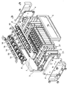
- FIG. 1 is an exploded perspective view illustrating an example of a battery module
- FIG. 2 is an exploded perspective view illustrating the configuration of the battery module
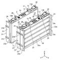
- FIG. 3 is a perspective view of a battery cell stack
- FIG. 4 is a diagram of battery cells and cell holders.
- FIG. 5 is an exploded perspective view
- FIG. 5 is an enlarged plan view showing a main part of the battery cell laminate
- FIG. 6 is an enlarged view of a portion A in FIG.
- the battery module 1 has a battery cell stack 3 in which a plurality of rectangular battery cells 2 are stacked and arranged.
- the battery cell laminate 3 holds each battery cell 2 sandwiched by cell holders 21 from the outside in the stacking direction.
- the cell holder 21 is interposed between the plurality of battery cells 2 and holds the plurality of battery cells 2.
- the battery cell stack 3 is perpendicular to the stacking direction of the battery cells 2 and a pair of end plates 4 disposed at both ends of the stacking direction of the battery cells 2 (X direction in FIG. 3). It is secured by a pair of side surface holding plates 5 arranged on both sides in the cell width direction (Y direction in FIG. 3).
- a circuit board 8 having a voltage detection circuit and a temperature measurement circuit is disposed between the gas exhaust duct 7 and the module cover 9.
- the bus bar holder 6 and the gas discharge duct 7 are arranged so as to extend along the stacking direction of the battery cells 2, respectively.
- the bus bar holder 6 and the gas discharge duct 7 are both made of an insulating synthetic resin material, and the bus bar holder 6 is made of a material having a larger elastic coefficient than the gas discharge duct 7.
- the bus bar holder 6 is composed of PP, and the gas discharge duct 7 is composed of PBT.
- the bus bar holder 6 is provided so as to be paired apart on both sides in the cell width direction of the battery cell stack 3, and a bus bar 16 that conductively connects between the positive external terminal 13A and the negative external terminal 13B of the adjacent battery cell 2. Is housed.
- the bus bar holder 6 functions as an insulating cover for the positive external terminal 13 ⁇ / b> A and the negative external terminal 13 ⁇ / b> B of the battery cell 2 and the bus bar 16.
- the gas discharge duct 7 is disposed at the center position in the cell width direction of the battery cell stack 3 and communicates with the gas discharge valve 14 of the battery cell 2.
- the gas discharge duct 7 discharges the exhaust gas discharged from the gas discharge valve 14 of the battery module 1. It leads to the outside and discharges.
- the module cover 9 is provided with a plurality of hooks 9 a and is locked to the bus bar holder 6 by hooking corresponding locking claws 6 a provided on the bus bar holder 6.
- the side surface holding plate 5 has a frame shape in which a rectangular opening 5 a is formed at the center of a flat plate portion extending along the side surface of the battery cell laminate 3, and flange pieces at both ends are end plate 4. Screwed on. A fixed bracket is attached to the end plate 4.
- the battery cell 2 has a flat rectangular battery container 11 that hermetically accommodates an electrode group and an electrolytic solution therein as shown in FIG. 4, for example.
- the battery case 11 has a rectangular bottom surface, a pair of wide main surfaces that are bent and raised at a pair of long side portions of the bottom surface, and a pair of narrow side surfaces that are bent and raised at a pair of short side portions of the bottom surface.
- the upper part facing the bottom surface is sealed by the battery lid 12.
- the battery lid 12 forms one surface of the battery container 11, and as shown in FIG. 4, a positive external terminal 13A and a negative external terminal 13B are provided on both sides of the cell width direction, and a gas discharge valve is provided at the center of the cell width direction. 14 is provided.
- the gas discharge valve 14 has a structure that is cleaved when the internal pressure of the battery container rises to a predetermined value or more and discharges the gas in the battery container.
- the cell holder 21 extends in a flat plate shape and faces a main surface facing wall portion 22 that faces one main surface of the battery cell 2, and protrudes from both end portions of the main surface facing wall portion 22, on both sides of the battery cell 2 in the cell width direction. It has the side surface opposing wall part 23 which each opposes a side surface.
- the main surface facing wall portion 22 is provided with a cell holding ridge portion 22a.
- the cell holding ridge 22a extends from the end on one side facing wall 23 side to the end on the other side facing wall 23 side with a constant width, and extends in the height direction of the cell holder 21.
- a plurality (five in this embodiment) are provided at predetermined intervals.
- the side facing wall portions 23 protrude in directions away from each other along the direction orthogonal to the main surface facing wall portion 22, and are connected to the side facing wall portions 23 of the adjacent cell holders 21 at respective tip portions.
- a connecting joint 23a for joining is provided.
- the connection joint portion 23a has a step shape, and is connected by overlapping with the connection joint portion 23a included in the side surface facing wall portion 23 of the adjacent cell holder 21, and is continuous in the stacking direction of the battery cell stack.
- the side facing wall portions 23 are formed so that the pitch between the cell holders 21 when connected is smaller than the thickness 2a of the battery cell 2, and are opposed to each other with a gap ⁇ , for example, as shown in FIG. It is like that. Therefore, even if the thickness of the battery cell 2 varies due to an error, the battery cell 2 can be reliably held by the cell holder 21.
- a plate engaging portion 23 b is provided on the outer surface of the side facing wall portion 23. As shown in FIG. 3, the plate engaging portion 23 b forms a convex portion that is continuous in a rectangular frame shape when the battery cell stack 3 is formed. Then, when the side surface holding plate 5 is mounted on the side surface of the battery cell laminate 3, the side surface holding plate 5 is inserted into the opening 5a of the side surface holding plate 5 and arranged along the edge of the opening 5a, and is engaged with the opening 5a. Then, the cell holder 21 is positioned with respect to the side surface holding plate 5.
- the cell holder 21 includes a first contact piece 24 and a second contact piece 25 that are in contact with the battery cover 12 of the battery cell 2 so as to face each other.
- the first contact piece 24 is provided at the upper end in the cell height direction of the main surface facing wall portion 22 and at the center in the cell width direction.
- the second contact piece 25 is provided at the upper end of the main surface facing wall portion 22 in the cell height direction and between the first contact piece 24 and both ends of the cell holder 21 in the cell width direction.
- the first abutment piece 24 and the second abutment piece 25 protrude in a direction perpendicular to the main surface facing wall portion 22, and come into contact with the battery lid 12 of the battery cell 2 to contact the battery cell 2.
- the movement of 2 in the cell height direction is restricted.
- the second contact piece 25 is not limited to the above-described configuration.
- the positive external terminal 13A and the negative external terminal 13B in the cell width direction It may be configured to extend from an intermediate position with respect to the gas discharge valve 14 to the vicinity of the bus bar holder locking portion 26 provided at both ends of the cell holder 21 in the cell width direction. With such a configuration, the battery lid of the battery cell 2 can be obtained. Accordingly, the creeping distance that abuts on the battery cell 12 can be ensured to be longer, and the movement of the battery cell 2 upward in the cell height direction can be reliably regulated.
- the lower end of the cell holder 21 in the cell height direction is opened so that the bottom surface of the battery cell 2 is exposed.
- the heat transfer efficiency is improved by arranging a heat transfer sheet or heat transfer grease on the bottom surface of each battery cell 2.
- the thermal resistance increases. Therefore, it is necessary for the heat transfer medium in contact with the battery cell 2 to improve the adhesion with the battery cell 2, and the heat transfer medium is adhered or compressed. And use.
- the heat transfer medium is closely attached and compressed to the bottom surface of the battery cell 2, stress is generated in the battery cell 2 from the lower side to the upper side in the cell height direction.
- the contact piece 25 contacts the battery lid 12 of the battery cell 2, the stress can be received, and the heat transfer medium and the battery cell 2 can be more closely contacted to reduce the thermal resistance.
- the cell holder 21 includes a bus bar holder locking portion 26 (first claw-shaped locking portion) for locking the bus bar holder 6 and a duct locking portion 27 (third claw) for locking the gas discharge duct 7. Shaped locking portion).
- the bus bar holder locking portion 26 and the duct locking portion 27 are provided so as to protrude upward from the upper end in the cell height direction of the main surface facing wall portion 22.
- the bus bar holder locking portion 26 is provided in pairs at the positions on both sides of the cell holder 21 in the cell width direction, and the positive external terminal 13A and the negative external terminal 13B of the battery cell 2 are connected to each other. They are arranged at positions facing each other with an interval between the outside and the inside in the cell width direction.
- the bus bar holder engaging portion 26 on the outer side in the cell width direction has a hook shape protruding toward the inner side in the cell width direction, and the bus bar holder engaging portion 26 on the inner side in the cell width direction protrudes toward the outer side in the cell width direction. It has a hook shape. That is, the bus bar holder engaging portion 26 on the outer side in the cell width direction and the bus bar holder engaging portion 26 on the inner side in the cell width direction have a hook shape that protrudes in a direction approaching each other.
- the duct locking part 27 is disposed at positions facing each other while being spaced apart at positions on both sides in the cell width direction with the gas discharge valve 14 of the battery cell 2 interposed therebetween. And it has the hook shape which protrudes in the direction which mutually approaches toward cell width direction inner side, respectively.
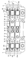
- FIGS. 7, is a perspective view of the bus bar holder
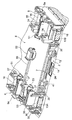
- FIGS. 8, 9 and 11 are enlarged perspective views of the main part of the battery module.
- FIGS. 10 and 12 are enlarged views of the main part of the battery module. It is a figure shown in a cross section.
- the bus bar holder 6 accommodates a plurality of bus bars 16 in an insulated state.
- the bus bar holder 6 includes a pair of side wall portions 33 that are opposed to each other in the cell width direction with the positive electrode external terminal 13A or the negative electrode external terminal 13B interposed therebetween, and a plurality of partition wall portions that are arranged at predetermined intervals in the stacking direction.
- the bus bar 16 is accommodated in a holding portion surrounded by the pair of side wall portions 33 and the partition wall portions 35 facing each other. An opening is provided on the bottom surface of the bus bar holder 6.
- the bus bar 16 is held with a clearance so as to be slidable in the cell height direction in a holding portion surrounded by the side wall portion 33 and the partition wall portion 35 of the bus bar holder 6.
- the pair of side wall portions 33 are provided with claw portions 34 facing the upper surface of the bus bar 16. The claw portion 34 prevents the bus bar 16 from slipping out upward in the cell height direction within the bus bar holder 6 and coming off from the bus bar holder 6.
- the bus bar holder 6 is provided with a cell holder locking portion 32 (second claw-shaped locking portion) for locking to the cell holder 21.
- the cell holder engaging portion 32 is provided separately on one side and the other side of the bus bar holder 6 in the cell width direction, and is positioned on both sides of the battery cell 2 with the positive electrode external terminal 13A and the negative electrode external terminal 13B interposed therebetween. And are arranged at positions facing each other. As shown in FIGS. 8 and 10, the cell holder engaging portion 32 on the outer side in the cell width direction has a hook shape protruding toward the outer side in the cell width direction, and is provided on the outer side in the cell width direction of the cell holder 21. The bus bar holder locking portion 26 is locked.
- the cell holder locking portion 32 on the inner side in the cell width direction has a hook shape protruding toward the inner side in the cell width direction, and is engaged with the bus bar holder locking portion 26 provided on the inner side in the cell width direction of the cell holder 21. Stopped. That is, the cell holder engaging portion 32 on the outer side in the cell width direction and the cell holder engaging portion 32 on the inner side in the cell width direction have a hook shape that protrudes in a direction away from each other.
- the bus bar holder 6 By pressing the bus bar holder 6 against the cell holder 21 from the upper side in the cell height direction of the cell holder 21, the cell holder locking part 32 of the bus bar holder 6 can be locked to the bus bar holder locking part 26 of the cell holder 21. Therefore, the bus bar holder 6 can be attached to the cell holder 21 with one touch, and the assembling work can be simplified. Further, the structure is simpler than the fastening structure using screws, and the appearance can be simplified.
- the gas discharge duct 7 is disposed to face the gas discharge valve 14 of the battery lid 12.
- the gas discharge duct 7 has a U-shaped cross section, and forms a closed cross section that continues in the stacking direction in cooperation with the battery lid 12 of each battery cell 2.
- the gas discharge duct 7 is provided with a sealing material 41 on a flange piece facing the battery lid 12, and is sealed so that gas does not leak from between the gas discharge duct 7 and the battery lid 12.
- the gas discharge duct 7 is provided with a cell holder locking portion 42 (fourth claw-shaped locking portion) for locking to the cell holder 21.
- the cell holder locking portion 42 is provided separately on one side and the other side of the gas discharge duct 7 in the cell width direction, and is arranged at a position facing the duct locking portion 27 of the cell holder 21 corresponding to each cell holder 21. Is done.
- the cell holder locking portion 42 has a hook shape that protrudes inward in the cell width direction, and is locked to the duct locking portion 27 of the cell holder 21.
- the gas discharge duct 7 can be pressed against the cell holder 21 from the upper side of the cell holder 21 in the cell height direction, so that the cell holder locking portion 42 of the gas discharge duct 7 can be locked to the duct locking portion 27 of the cell holder 21. Therefore, the gas discharge duct 7 can be attached to the cell holder 21 with one touch, and the assembling work can be simplified. Further, similarly to the bus bar holder 6, the structure is simpler than the fastening structure using screws, and the appearance can be simplified.
- the work of fastening screws in assembly work can be omitted, the number of parts can be reduced, the production and assembly costs can be reduced, and the product can be reduced. It can be provided at low cost. Moreover, the use of metal parts such as screws can be suppressed as much as possible, and the risk of electric shock and the like can be reduced.
- the circuit board 8 is locked to a pair of bus bar holders 6 arranged on both sides of the circuit board 8 in the cell width direction.
- the bus bar holder 6 has a board base part 36 on which the circuit board 8 is placed and a circuit board locking part 37 (fifth claw-like locking part).
- the circuit board locking portion 37 is provided at an end portion on the inner side in the cell width direction of the bus bar holder 6 and protrudes toward the inner side in the cell width direction of the battery cell stack 3. It has a shape.
- the circuit board 8 is pressed toward the gas discharge duct 7 from the upper side in the cell height direction, thereby elastically deforming the circuit board locking portion 37 and passing the end portion of the circuit board 8.
- the end of the circuit board 8 is held between the bus bar holder 6 and the board pedestal 36.
- the circuit board 8 is fastened with screws to the cell holders 21 whose four corners are at both ends in the stacking direction. Therefore, for example, gas is ejected from the gas discharge valve 14 of the battery cell 2 and the gas discharge duct 7 is urged toward the upper side in the cell height direction. As a result, the claw engagement with the cell holder 21 is released. However, it can contact the circuit board 8 and prevent further movement.
- the circuit board 8 is provided with a voltage detection terminal 51 for detecting the voltage of the battery cell 2 and a wiring connector 52 for a temperature measurement sensor.
- the voltage detection terminal 51 protrudes outward in the cell width direction, and is conductively connected to the bus bar 16 by the relay terminal 53.
- the voltage detection circuit on the circuit board 8 detects the voltage of the battery cell 2 from the bus bar 16 via the voltage detection terminal 51.
- the temperature measurement sensor 55 is detachably attached to the bus bar holder 6.
- the temperature measurement sensor 55 is supported by the bus bar holder 6 via an elastic support member, and is in contact with the battery cell 2 with a predetermined pressing force.
- the wiring 56 of the temperature measurement sensor 55 is supported by a cable support portion 38 provided in the bus bar holder 6, and the socket at the tip is connected to the wiring connector 52.
- the temperature measurement circuit on the circuit board 8 measures the temperature of the battery cell 2 based on the signal from the temperature measurement sensor 55.
- a method for assembling the battery module 1 having the above configuration will be described.
- a plurality of battery cells 2 are sandwiched and stacked between cell holders 21 to assemble the battery cell stack 3 shown in FIG.
- the end plate 4 is arranged and compressed outside the battery cell stack 3 in the stacking direction, and the side surface holding plates 5 are mounted on both sides of the battery cell stack 3 in the cell width direction.
- the plate engaging portion 23b of the side facing wall portion 23 of the cell holder 21 protruding from the side surface of the battery cell stack 3 is inserted into the opening portion 5a of the side surface holding plate 5 to be engaged therewith.
- Each cell holder 21 is positioned with respect to.
- the side surface holding plate 5 is bolted to the end plate 4.
- the battery cell laminated body 3 can be secured by the above assembly operation.
- a bus bar 16 is attached to the bus bar holder 6 in advance.
- the bus bar holder 6 is set on the battery cell stack 3 from the upper side of the battery cell stack 3 in the cell height direction, and the positive external terminal 13A and the negative external terminal 13B of each battery cell 2 are inserted into the bus bar holder 6. Then, the bus bar holder 6 is pressed against the battery cell stack 3 with a predetermined pressing force, and the cell holder locking portion 32 of the bus bar holder 6 is locked to the bus bar holder locking portion 26 of the cell holder 21.
- the cell holder locking portion 32 and the bus bar holder locking portion 26 have hook shapes, they can be easily locked with each other. In addition, when at least one of them is elastically deformed, it is possible to absorb a dimensional error and to be surely locked.
- the bus bar holder 6 is fixed integrally to the cell holder 21 of the battery cell stack 3. After the pair of bus bar holders 6 are attached to the battery cell laminate 3, the bus bar 16 is welded to the positive external terminal 13A and the negative external terminal 13B of the battery cell 2.
- the bus bar holder 6 encloses a plurality of bus bars 16 with a clearance on the upper surface or the lower surface, and accommodates them slidable in the cell height direction. Therefore, by attaching the bus bar holder 6 to the battery cell stack 3, each bus bar 16 can be easily set on the positive external terminal 13A and the negative external terminal 13B of the adjacent battery cell 2, and the bus bar 16 is connected to the positive external terminal 13A and the positive external terminal 13A. The work of welding and joining to the negative electrode external terminal 13B can be easily performed.
- the gas discharge duct 7 is set on the battery cell stack 3 and pressed against the battery cell stack 3 with a predetermined pressing force, so that the cell holder engaging portion 42 of the gas discharge duct 7 is connected to the duct of the cell holder 21.
- the locking portion 27 is locked. Since the cell holder engaging portion 42 and the duct engaging portion 27 have hook shapes, they can be easily engaged with each other. In addition, when at least one of them is elastically deformed, it is possible to absorb a dimensional error and to be surely locked.
- the gas discharge duct 7 is integrally fixed to the cell holder 21 of the battery cell stack 3 by this locking.
- the order of attaching the bus bar holder 6 and the gas discharge duct 7 may be either.
- the bus bar 16 may be welded to the positive external terminal 13A and the negative external terminal 13B of the battery cell 2 after the bus bar holder 6 and the gas discharge duct 7 are attached.
- the circuit board 8 is attached.
- the circuit board 8 is disposed above the gas discharge duct 7 and is pushed in with a predetermined pressing force to be locked to the circuit board locking portion 37 of the bus bar holder 6.
- the four corners of the circuit board 8 are fastened with screws to the cell holders 21 at both ends in the stacking direction.
- the voltage detection terminal 51 is conductively connected to the bus bar 16 using the relay terminal 53.
- the temperature measurement sensor 55 is mounted on the bus bar holder 6, the wiring 56 is supported by the cable support portion 38, and the socket is connected to the wiring connector 52. And after connecting the cable etc. which are not shown in figure, the module cover 9 is attached.
- the bus bar holder locking portion 26 and the cell holder locking portion 32 having a hook shape are locked with each other. It is possible to absorb the dimensional error of the assembly parts and securely assemble them together.
- the cell holder 21 and the gas discharge duct 7 are connected to each other by the engaging portions. By stopping, the cell holder 21 can be made thinner, and the outer shape of the secondary battery module can be made small, light weight, and low cost.
- a plurality of duct locking portions 27 and cell holder locking portions 42 are provided and locked, so that the exhaust pressure can be dispersed, the pressure due to gas diffusion is reduced, and Damage can be prevented.
- the force applied from the structural members such as the bus bar 16, the temperature measurement sensor 55, the gas discharge duct 7, the circuit board 8, and the wiring is transmitted from the plurality of cell holder locking portions 32 of the bus bar holder 6 to the cell holder 21. Therefore, the stress on the electrode portion of the battery can be reduced as compared with a conventional battery module in which a bus bar, a voltage detection circuit, wiring, and the like are fixed to the electrode portion.
- FIG. 13 and 14 are perspective views showing other examples of the bus bar holder.
- the case where the bus bar holder 6 and the gas discharge duct 7 are configured separately has been described as an example.
- FIG. By adopting an integrally molded configuration, the number of parts can be reduced, and the number of assembling steps can be reduced to reduce the manufacturing cost.
- the bus bar holder 6 and the gas discharge duct 7 are configured integrally, for example, when the bus bar holder 6 and the gas discharge duct 7 are configured by the same synthetic resin material, it is necessary to use a synthetic resin having a relatively high elastic modulus in order to ensure the elasticity of the locking portion. If the heat resistance is low, it may be difficult to satisfy the heat resistance requirement of the gas discharge duct 7. Therefore, in such a case, a metal film may be stuck inside the gas discharge duct 7 to ensure heat resistance.
- the case where the bus bar holder 6 on one side in the cell width direction and the bus bar holder 6 on the other side in the cell width direction are provided separately is described.
- the pair of bus bar holders 6 may be connected to each other by a plurality of ribs 39 extending in an integral manner.
- the number of parts can be reduced, the number of assembly steps can be reduced, and the manufacturing cost can be kept low.
- the gas discharge duct 7 is disposed on the rib 39.
- the present invention is not limited to the above-described embodiments, and various designs can be made without departing from the spirit of the present invention described in the claims. It can be changed.
- the above-described embodiment has been described in detail for easy understanding of the present invention, and is not necessarily limited to one having all the configurations described.
- a part of the configuration of an embodiment can be replaced with the configuration of another embodiment, and the configuration of another embodiment can be added to the configuration of an embodiment.
Abstract
Description
なお、各図において、同一の名称、符号については同一もしくは同質の材料を示しており、重複する説明は省略する。また、各図が示す部材の大きさや形状は一例であり、特許請求の範囲に示される部材等の形態を限定するものではない。以下の実施例では、電池モジュールがHEVやEV等の車両用の電池モジュールの場合を例に説明するが、民生用、産業用を問わずに用いることができ、例えば固定配置型の蓄電装置として用いることもできる。
まず、図4に示すように、複数の電池セル2をセルホルダ21で挟み込んで積層させ、図3に示す電池セル積層体3を組み立てる。そして、電池セル積層体3の積層方向外側に端部プレート4を配置して圧縮し、電池セル積層体3のセル幅方向両側に側面保持プレート5を装着する。その際、電池セル積層体3の側面に突出しているセルホルダ21の側面対向壁部23のプレート係合部23bを、側面保持プレート5の開口部5aに挿入して係合させ、側面保持プレート5に対して各セルホルダ21を位置決めする。そして、側面保持プレート5を端部プレート4にボルト結合する。以上の組立作業により、電池セル積層体3を固縛することができる。
2 電池セル
3 電池セル積層体
6 バスバホルダ
7 ガス排出ダクト
8 回路基板
11 電池容器
12 電池蓋(一面)
13A 正極外部端子(外部端子)
13B 負極外部端子(外部端子)
14 ガス排出弁
16 バスバ
21 セルホルダ
26 バスバホルダ係止部(第1の爪状係止部)
27 ダクト係止部(第3の爪状係止部)
32 セルホルダ係止部(第2の爪状係止部)
37 回路基板係止部(第5の爪状係止部)
42 セルホルダ係止部(第4の爪状係止部)
Claims (10)
- 角形の電池容器の一面に外部端子を有する複数の電池セルを配列させて互いに隣接する前記外部端子の間をバスバで導電接続した電池モジュールであって、
前記複数の電池セルの間に介在されて前記複数の電池セルを保持するセルホルダと、
該セルホルダに取り付けられて前記バスバを保持するバスバホルダと、を有し、
前記セルホルダに設けられた第1の爪状係止部と、前記バスバホルダに設けられた第2の爪状係止部とが互いに係止することを特徴とする電池モジュール。 - 前記第1の爪状係止部は、前記電池セルのセル幅方向に離間して対をなして設けられており、互いに接近する方向に向かって突出するフック形状を有し、
前記第2の爪状係止部は、前記電池セルのセル幅方向に離間して対をなして設けられており、互いに離間する方向に向かって突出するフック形状を有していることを特徴とする請求項1に記載の電池モジュール。 - 前記電池セルの一面に設けられたガス排出弁に対向して配置されるガス排出ダクトを有し、
前記セルホルダに設けられた第3の爪状係止部と、前記ガス排出ダクトに設けられた第4の爪状係止部とが互いに係止することを特徴とする請求項2に記載の電池モジュール。 - 前記第3の爪状係止部は、前記電池セルのセル幅方向に離間して対をなして設けられており、互いに接近する方向に向かって突出するフック形状を有し、
前記第4の爪状係止部は、前記電池セルのセル幅方向に離間して対をなして設けられており、互いに離間する方向に向かって突出するフック形状を有していることを特徴とする請求項3に記載の電池モジュール。 - 前記ガス排出ダクトの上に回路基板が配置されており、該回路基板は、前記バスバホルダに設けられている第5の爪状係止部によって前記バスバホルダに係止されていることを特徴とする請求項4に記載の電池モジュール。
- 前記バスバホルダは、前記電池セルのセル幅方向一方側と他方側に離間してそれぞれ設けられ、
前記ガス排出ダクトは、一方のバスバホルダと他方のバスバホルダとの間に配置され、
前記回路基板は、前記ガス排出ダクトの上に配置されて、セル幅方向両側の端部が前記
一方のバスバホルダに設けられている前記第5の爪状係止部と前記他方のバスバホルダに設けられている前記第5の爪状係止部に係止されていることを特徴とする請求項5に記載の電池モジュール。 - 前記第5の爪状係止部は、前記バスバホルダのセル幅方向内側の端部から突出するフック形状を有していることを特徴とする請求項6に記載の電池モジュール。
- 前記バスバホルダは、前記バスバの上面または下面にクリアランスを持って前記バスバを内包することを特徴とする請求項1に記載の電池モジュール。
- 前記バスバホルダと前記ガス排出ダクトが一体に形成されていることを特徴とする請求項3に記載の電池モジュール。
- 前記バスバホルダは、前記セルホルダよりも弾性係数が大きい材料により構成されていることを特徴とする請求項1に記載の電池モジュール。
Priority Applications (4)
| Application Number | Priority Date | Filing Date | Title |
|---|---|---|---|
| US15/572,235 US10637019B2 (en) | 2015-07-09 | 2016-06-22 | Cell module |
| JP2017527166A JP6395935B2 (ja) | 2015-07-09 | 2016-06-22 | 電池モジュール |
| EP16821233.0A EP3321994B1 (en) | 2015-07-09 | 2016-06-22 | Cell module |
| CN201680025096.4A CN107534112B (zh) | 2015-07-09 | 2016-06-22 | 电池组件 |
Applications Claiming Priority (2)
| Application Number | Priority Date | Filing Date | Title |
|---|---|---|---|
| JP2015-137648 | 2015-07-09 | ||
| JP2015137648 | 2015-07-09 |
Publications (1)
| Publication Number | Publication Date |
|---|---|
| WO2017006763A1 true WO2017006763A1 (ja) | 2017-01-12 |
Family
ID=57685108
Family Applications (1)
| Application Number | Title | Priority Date | Filing Date |
|---|---|---|---|
| PCT/JP2016/068453 WO2017006763A1 (ja) | 2015-07-09 | 2016-06-22 | 電池モジュール |
Country Status (5)
| Country | Link |
|---|---|
| US (1) | US10637019B2 (ja) |
| EP (1) | EP3321994B1 (ja) |
| JP (1) | JP6395935B2 (ja) |
| CN (1) | CN107534112B (ja) |
| WO (1) | WO2017006763A1 (ja) |
Cited By (14)
| Publication number | Priority date | Publication date | Assignee | Title |
|---|---|---|---|---|
| JP2018081876A (ja) * | 2016-11-18 | 2018-05-24 | 矢崎総業株式会社 | 導電モジュール及び電池パック |
| WO2018155093A1 (ja) * | 2017-02-27 | 2018-08-30 | 日立オートモティブシステムズ株式会社 | 二次電池モジュール |
| WO2019088789A1 (ko) * | 2017-11-06 | 2019-05-09 | 주식회사 엘지화학 | 전지 모듈 |
| WO2019123930A1 (ja) * | 2017-12-18 | 2019-06-27 | 日立オートモティブシステムズ株式会社 | 電池モジュール |
| JP2019220437A (ja) * | 2018-06-22 | 2019-12-26 | 本田技研工業株式会社 | バッテリモジュール |
| JP2019220436A (ja) * | 2018-06-22 | 2019-12-26 | 本田技研工業株式会社 | バッテリモジュール |
| JP2020035733A (ja) * | 2018-08-23 | 2020-03-05 | 本田技研工業株式会社 | バッテリモジュール |
| CN112335108A (zh) * | 2018-10-10 | 2021-02-05 | 株式会社Lg化学 | 汇流条框架安装方法 |
| WO2021079937A1 (ja) | 2019-10-23 | 2021-04-29 | 株式会社Gsユアサ | 蓄電装置 |
| WO2021079936A1 (ja) * | 2019-10-23 | 2021-04-29 | 株式会社Gsユアサ | 蓄電装置 |
| JP2021068559A (ja) * | 2019-10-23 | 2021-04-30 | 株式会社Gsユアサ | 蓄電装置 |
| US20210218082A1 (en) * | 2018-09-26 | 2021-07-15 | Vehicle Energy Japan Inc. | Battery pack |
| US11769924B2 (en) | 2018-06-22 | 2023-09-26 | Gs Yuasa International Ltd. | Energy storage apparatus |
| JP7400340B2 (ja) | 2019-10-23 | 2023-12-19 | 株式会社Gsユアサ | 蓄電装置 |
Families Citing this family (11)
| Publication number | Priority date | Publication date | Assignee | Title |
|---|---|---|---|---|
| TWI653456B (zh) * | 2017-08-23 | 2019-03-11 | 致茂電子股份有限公司 | 電池化成裝置及其針盤結構 |
| KR102159347B1 (ko) * | 2017-11-14 | 2020-09-23 | 주식회사 엘지화학 | 배터리 셀 가압형 엔드 플레이트와 확장형 센싱 하우징 구조가 적용된 배터리 모듈 |
| DE102018206231B3 (de) * | 2018-04-23 | 2019-09-19 | Triathlon Batterien Gmbh | Vorrichtung zum elektrischen Kontaktieren einer Leiterplatte an ein Batteriezellenverbundsystem und Einrichtung mit einer derartigen Vorrichtung und einem derartigen Batteriezellenverbundsystem |
| CN110858672B (zh) * | 2018-08-23 | 2023-02-21 | 本田技研工业株式会社 | 电池模块 |
| JP7077932B2 (ja) * | 2018-12-25 | 2022-05-31 | 株式会社オートネットワーク技術研究所 | 接続モジュール |
| US11777149B2 (en) | 2019-03-01 | 2023-10-03 | Paladin Power, Inc. | Stackable battery bussing system |
| CN111864155A (zh) * | 2019-04-30 | 2020-10-30 | 宁德时代新能源科技股份有限公司 | 电池模组及电池包 |
| JP2020187978A (ja) * | 2019-05-17 | 2020-11-19 | 矢崎総業株式会社 | バスバモジュール |
| CN111403845B (zh) * | 2020-03-28 | 2022-07-15 | 哈尔滨工程大学 | 一种可排废气的动力电池极耳散热系统 |
| DE102020110700A1 (de) * | 2020-04-20 | 2021-10-21 | Audi Aktiengesellschaft | Batterie für ein Kraftfahrzeug sowie Verfahren zum Herstellen einer Batterie für ein Kraftfahrzeug |
| EP4358267A1 (en) * | 2022-10-20 | 2024-04-24 | Prime Planet Energy & Solutions, Inc. | Battery module |
Citations (5)
| Publication number | Priority date | Publication date | Assignee | Title |
|---|---|---|---|---|
| JP2010080135A (ja) * | 2008-09-24 | 2010-04-08 | Sanyo Electric Co Ltd | バッテリシステム |
| JP2011113702A (ja) * | 2009-11-25 | 2011-06-09 | Kojima Press Industry Co Ltd | 積層体へのチャンバダクト取付け構造 |
| JP2012248482A (ja) * | 2011-05-30 | 2012-12-13 | Toshiba Corp | 二次電池装置 |
| WO2013084941A1 (ja) * | 2011-12-09 | 2013-06-13 | 本田技研工業株式会社 | バッテリモジュール |
| WO2015033795A1 (ja) * | 2013-09-05 | 2015-03-12 | 株式会社 豊田自動織機 | 電池モジュール |
Family Cites Families (15)
| Publication number | Priority date | Publication date | Assignee | Title |
|---|---|---|---|---|
| JP4374385B2 (ja) * | 2007-07-24 | 2009-12-02 | 本田技研工業株式会社 | 車両のインナーガーニッシュの組付部構造 |
| CN201531490U (zh) | 2009-11-09 | 2010-07-21 | 神讯电脑(昆山)有限公司 | 卡钩结构 |
| JP2011222419A (ja) * | 2010-04-13 | 2011-11-04 | Sanyo Electric Co Ltd | バッテリシステム及びこのバッテリシステムを搭載する車両 |
| JP5612904B2 (ja) * | 2010-05-13 | 2014-10-22 | 矢崎総業株式会社 | カバー部材及び該カバー部材を備えた電源装置 |
| CN103733382B (zh) | 2011-06-28 | 2016-03-30 | 矢崎总业株式会社 | 汇流条板 |
| JP5834769B2 (ja) * | 2011-10-26 | 2015-12-24 | 株式会社オートネットワーク技術研究所 | 電池用配線モジュール |
| JP2013152917A (ja) * | 2011-12-26 | 2013-08-08 | Auto Network Gijutsu Kenkyusho:Kk | 配線モジュール |
| JP5850338B2 (ja) | 2012-10-16 | 2016-02-03 | 住友電装株式会社 | 位置ずれ吸収部材及びバスバーユニット |
| JP6060180B2 (ja) * | 2012-12-28 | 2017-01-11 | 日立オートモティブシステムズ株式会社 | 組電池 |
| JP6220536B2 (ja) * | 2013-03-25 | 2017-10-25 | 矢崎総業株式会社 | 電池集合体のダクト保持構造 |
| US9831482B2 (en) * | 2013-09-06 | 2017-11-28 | Johnson Controls Technology Company | Battery module lid system and method |
| JP6198061B2 (ja) * | 2013-10-28 | 2017-09-20 | 株式会社オートネットワーク技術研究所 | 配線モジュール |
| KR102248596B1 (ko) * | 2014-04-11 | 2021-05-06 | 삼성에스디아이 주식회사 | 배터리 모듈 |
| CN104309707A (zh) * | 2014-10-28 | 2015-01-28 | 天津博信汽车零部件有限公司 | 汽车及其机舱隔板和通风窗盖板安装结构 |
| JP6494754B2 (ja) * | 2015-06-12 | 2019-04-03 | 日立オートモティブシステムズ株式会社 | 電池モジュール |
-
2016
- 2016-06-22 WO PCT/JP2016/068453 patent/WO2017006763A1/ja active Application Filing
- 2016-06-22 CN CN201680025096.4A patent/CN107534112B/zh active Active
- 2016-06-22 JP JP2017527166A patent/JP6395935B2/ja active Active
- 2016-06-22 US US15/572,235 patent/US10637019B2/en active Active
- 2016-06-22 EP EP16821233.0A patent/EP3321994B1/en active Active
Patent Citations (5)
| Publication number | Priority date | Publication date | Assignee | Title |
|---|---|---|---|---|
| JP2010080135A (ja) * | 2008-09-24 | 2010-04-08 | Sanyo Electric Co Ltd | バッテリシステム |
| JP2011113702A (ja) * | 2009-11-25 | 2011-06-09 | Kojima Press Industry Co Ltd | 積層体へのチャンバダクト取付け構造 |
| JP2012248482A (ja) * | 2011-05-30 | 2012-12-13 | Toshiba Corp | 二次電池装置 |
| WO2013084941A1 (ja) * | 2011-12-09 | 2013-06-13 | 本田技研工業株式会社 | バッテリモジュール |
| WO2015033795A1 (ja) * | 2013-09-05 | 2015-03-12 | 株式会社 豊田自動織機 | 電池モジュール |
Non-Patent Citations (1)
| Title |
|---|
| See also references of EP3321994A4 * |
Cited By (26)
| Publication number | Priority date | Publication date | Assignee | Title |
|---|---|---|---|---|
| JP2018081876A (ja) * | 2016-11-18 | 2018-05-24 | 矢崎総業株式会社 | 導電モジュール及び電池パック |
| WO2018155093A1 (ja) * | 2017-02-27 | 2018-08-30 | 日立オートモティブシステムズ株式会社 | 二次電池モジュール |
| US11811031B2 (en) | 2017-11-06 | 2023-11-07 | Lg Energy Solution, Ltd. | Battery module |
| WO2019088789A1 (ko) * | 2017-11-06 | 2019-05-09 | 주식회사 엘지화학 | 전지 모듈 |
| KR20190051297A (ko) * | 2017-11-06 | 2019-05-15 | 주식회사 엘지화학 | 전지 모듈 |
| KR102327049B1 (ko) * | 2017-11-06 | 2021-11-15 | 주식회사 엘지에너지솔루션 | 전지 모듈 |
| CN111712940A (zh) * | 2017-12-18 | 2020-09-25 | 日本汽车能源株式会社 | 电池模块 |
| JPWO2019123930A1 (ja) * | 2017-12-18 | 2020-12-03 | ビークルエナジージャパン株式会社 | 電池モジュール |
| CN111712940B (zh) * | 2017-12-18 | 2023-07-18 | 日本汽车能源株式会社 | 电池模块 |
| US11563251B2 (en) | 2017-12-18 | 2023-01-24 | Vehicle Energy Japan Inc. | Battery module |
| WO2019123930A1 (ja) * | 2017-12-18 | 2019-06-27 | 日立オートモティブシステムズ株式会社 | 電池モジュール |
| JP6995882B2 (ja) | 2017-12-18 | 2022-01-17 | ビークルエナジージャパン株式会社 | 電池モジュール |
| EP3731299A4 (en) * | 2017-12-18 | 2021-09-08 | Vehicle Energy Japan Inc. | BATTERY MODULE |
| JP2019220436A (ja) * | 2018-06-22 | 2019-12-26 | 本田技研工業株式会社 | バッテリモジュール |
| JP2019220437A (ja) * | 2018-06-22 | 2019-12-26 | 本田技研工業株式会社 | バッテリモジュール |
| US11769924B2 (en) | 2018-06-22 | 2023-09-26 | Gs Yuasa International Ltd. | Energy storage apparatus |
| JP7042203B2 (ja) | 2018-08-23 | 2022-03-25 | 本田技研工業株式会社 | バッテリモジュール |
| JP2020035733A (ja) * | 2018-08-23 | 2020-03-05 | 本田技研工業株式会社 | バッテリモジュール |
| US20210218082A1 (en) * | 2018-09-26 | 2021-07-15 | Vehicle Energy Japan Inc. | Battery pack |
| CN112335108A (zh) * | 2018-10-10 | 2021-02-05 | 株式会社Lg化学 | 汇流条框架安装方法 |
| US11962039B2 (en) | 2018-10-10 | 2024-04-16 | Lg Energy Solution, Ltd. | Mounting method of bus-bar frame |
| JP2021068559A (ja) * | 2019-10-23 | 2021-04-30 | 株式会社Gsユアサ | 蓄電装置 |
| WO2021079936A1 (ja) * | 2019-10-23 | 2021-04-29 | 株式会社Gsユアサ | 蓄電装置 |
| WO2021079937A1 (ja) | 2019-10-23 | 2021-04-29 | 株式会社Gsユアサ | 蓄電装置 |
| JP7380075B2 (ja) | 2019-10-23 | 2023-11-15 | 株式会社Gsユアサ | 蓄電装置 |
| JP7400340B2 (ja) | 2019-10-23 | 2023-12-19 | 株式会社Gsユアサ | 蓄電装置 |
Also Published As
| Publication number | Publication date |
|---|---|
| CN107534112A (zh) | 2018-01-02 |
| EP3321994B1 (en) | 2023-03-08 |
| US10637019B2 (en) | 2020-04-28 |
| JP6395935B2 (ja) | 2018-09-26 |
| EP3321994A4 (en) | 2019-03-27 |
| EP3321994A1 (en) | 2018-05-16 |
| CN107534112B (zh) | 2020-10-02 |
| JPWO2017006763A1 (ja) | 2018-03-01 |
| US20180151859A1 (en) | 2018-05-31 |
Similar Documents
| Publication | Publication Date | Title |
|---|---|---|
| JP6395935B2 (ja) | 電池モジュール | |
| JP5745938B2 (ja) | 二次電池装置 | |
| US9097771B2 (en) | Voltage sensing assembly and battery module including the same | |
| US8951653B2 (en) | Battery module with thermistor supporter | |
| WO2015181930A1 (ja) | 蓄電モジュール | |
| WO2014103007A1 (ja) | 組電池 | |
| US9437878B2 (en) | Electricity storage module | |
| US9012063B2 (en) | Battery module | |
| US20160104873A1 (en) | Battery pack system and method for fabrication thereof | |
| WO2016199563A1 (ja) | 電池モジュール | |
| US20150372268A1 (en) | Duct holding structure for battery assembly body | |
| US20200287194A1 (en) | Electrical connecting member housing case and battery module | |
| US20190372065A1 (en) | Battery pack | |
| JP6465354B2 (ja) | 蓄電モジュール | |
| JP2012013564A (ja) | 温度センサの取付構造 | |
| US9847561B2 (en) | Cell cooling frames with cantilevered side seals | |
| JP2014179196A (ja) | 二次電池の接続構造およびこれを備えた二次電池装置 | |
| JP2018133152A (ja) | 電池モジュール及び電池パック | |
| US11563251B2 (en) | Battery module | |
| US11502361B2 (en) | Energy storage apparatus | |
| US11742154B2 (en) | Electricity storage module and electricity storage unit | |
| CN116114105A (zh) | 具有使用磁力的固定装置的电池组及其制造方法、更换电池组的电池单元的方法 | |
| US20240128567A1 (en) | Battery system, battery module and battery string | |
| JP6264245B2 (ja) | ハーネス取付構造及び電池パック | |
| JP2017174655A (ja) | 電池パック及び電池パックの製造方法 |
Legal Events
| Date | Code | Title | Description |
|---|---|---|---|
| 121 | Ep: the epo has been informed by wipo that ep was designated in this application |
Ref document number: 16821233 Country of ref document: EP Kind code of ref document: A1 |
|
| ENP | Entry into the national phase |
Ref document number: 2017527166 Country of ref document: JP Kind code of ref document: A |
|
| REEP | Request for entry into the european phase |
Ref document number: 2016821233 Country of ref document: EP |
|
| WWE | Wipo information: entry into national phase |
Ref document number: 15572235 Country of ref document: US |
|
| NENP | Non-entry into the national phase |
Ref country code: DE |