WO2017006683A1 - ブラスト加工装置およびブラスト加工による製品製造方法 - Google Patents
ブラスト加工装置およびブラスト加工による製品製造方法 Download PDFInfo
- Publication number
- WO2017006683A1 WO2017006683A1 PCT/JP2016/066854 JP2016066854W WO2017006683A1 WO 2017006683 A1 WO2017006683 A1 WO 2017006683A1 JP 2016066854 W JP2016066854 W JP 2016066854W WO 2017006683 A1 WO2017006683 A1 WO 2017006683A1
- Authority
- WO
- WIPO (PCT)
- Prior art keywords
- nozzle
- workpiece
- blasting
- product
- abrasive grains
- Prior art date
- Legal status (The legal status is an assumption and is not a legal conclusion. Google has not performed a legal analysis and makes no representation as to the accuracy of the status listed.)
- Ceased
Links
Images




Classifications
-
- B—PERFORMING OPERATIONS; TRANSPORTING
- B23—MACHINE TOOLS; METAL-WORKING NOT OTHERWISE PROVIDED FOR
- B23K—SOLDERING OR UNSOLDERING; WELDING; CLADDING OR PLATING BY SOLDERING OR WELDING; CUTTING BY APPLYING HEAT LOCALLY, e.g. FLAME CUTTING; WORKING BY LASER BEAM
- B23K26/00—Working by laser beam, e.g. welding, cutting or boring
- B23K26/18—Working by laser beam, e.g. welding, cutting or boring using absorbing layers on the workpiece, e.g. for marking or protecting purposes
-
- B—PERFORMING OPERATIONS; TRANSPORTING
- B23—MACHINE TOOLS; METAL-WORKING NOT OTHERWISE PROVIDED FOR
- B23K—SOLDERING OR UNSOLDERING; WELDING; CLADDING OR PLATING BY SOLDERING OR WELDING; CUTTING BY APPLYING HEAT LOCALLY, e.g. FLAME CUTTING; WORKING BY LASER BEAM
- B23K26/00—Working by laser beam, e.g. welding, cutting or boring
- B23K26/36—Removing material
- B23K26/361—Removing material for deburring or mechanical trimming
-
- B—PERFORMING OPERATIONS; TRANSPORTING
- B24—GRINDING; POLISHING
- B24C—ABRASIVE OR RELATED BLASTING WITH PARTICULATE MATERIAL
- B24C1/00—Methods for use of abrasive blasting for producing particular effects; Use of auxiliary equipment in connection with such methods
- B24C1/04—Methods for use of abrasive blasting for producing particular effects; Use of auxiliary equipment in connection with such methods for treating only selected parts of a surface, e.g. for carving stone or glass
-
- B—PERFORMING OPERATIONS; TRANSPORTING
- B24—GRINDING; POLISHING
- B24C—ABRASIVE OR RELATED BLASTING WITH PARTICULATE MATERIAL
- B24C5/00—Devices or accessories for generating abrasive blasts
- B24C5/02—Blast guns, e.g. for generating high velocity abrasive fluid jets for cutting materials
-
- B—PERFORMING OPERATIONS; TRANSPORTING
- B24—GRINDING; POLISHING
- B24C—ABRASIVE OR RELATED BLASTING WITH PARTICULATE MATERIAL
- B24C5/00—Devices or accessories for generating abrasive blasts
- B24C5/02—Blast guns, e.g. for generating high velocity abrasive fluid jets for cutting materials
- B24C5/04—Nozzles therefor
Definitions
- the present invention relates to a blasting apparatus and a product manufacturing method using blasting.
- Chemically tempered glass is used as a cover glass used for smartphones. This cover glass is manufactured by cutting a large glass to which a plurality of cover glass sizes are assigned. Chemically tempered glass includes a sheet type that is chemically tempered before cutting and a cell type that is chemically tempered after cutting. Chemically tempered glass has a compressive stress on the surface, is difficult to cut, has poor cutting quality, and a poor yield rate. As a cover glass used for smartphones, sheet types are generally not preferred and are not tempered. The cell type that cuts at is the mainstream. Large glass is cut by blasting using CNC milling or a pen-shaped nozzle. Moreover, it may be cut using a dicing saw or a diamond scriber.
- the initial investment amount of the apparatus can be suppressed as compared with the laser processing method.
- the processing efficiency of the blast processing method is lower than that of the laser processing method.
- a plurality of pen-shaped nozzles are attached to a blasting machine to simultaneously process a plurality of tempered glasses.
- a film (resist film) is pasted on both sides of the glass plate, and the film on the processing line (cutting line that cuts the glass) is cut with a cutter, exposure / development, laser light, etc. After removing by blasting.
- ⁇ Processing for each nozzle in the blast processing method is slower than laser processing.
- the pen-shaped nozzle When processing a round hole with a pen-shaped nozzle, the pen-shaped nozzle must be finely circulated (moved). For example, as shown in FIG. 6, when processing is performed on the glass substrate 3 to form the outer edge 3A and the openings 3B and 3C using the pen-shaped nozzle 100, the direction of the arrow indicated by the arrow in FIG. It is necessary to move the nozzle. Since the moving distance of the nozzle is long, the processing efficiency is low.
- nozzle injection port and the glass plate have the same size and shape, a plurality of processed portions provided on the glass plate can be processed simultaneously.
- the processing range is wider than that of the pen-shaped nozzle, the spraying pressure of the abrasive grains is dispersed, resulting in a slow processing speed.
- the abrasive grains are reflected. Since the abrasive grains injected from the injection port and the reflected abrasive grains collide, stable injection of the abrasive grains becomes difficult, and the processing speed decreases (the processing time increases). Moreover, the collection rate (ratio which can reuse the used grinding abrasive grain) falls. In particular, when the central axis of the nozzle is at right angles to the glass plate, the above-described problem due to reflection of the abrasive grains occurs. In addition, when the nozzle feed rate is slowed down, the influence of the reflected abrasive grains increases.
- the present invention has been made in view of the above problems.
- a blasting apparatus is a blasting apparatus that performs blasting at a work portion of the work piece by injecting abrasive grains onto the work piece while moving on the work piece.
- the slit-shaped longitudinal direction is tilted by a predetermined angle with respect to the moving direction of the nozzle, and the projection of the injection port onto the workpiece causes the workpiece to be processed. It is possible to arrange the nozzle so as to enclose it.
- an outer edge of a product can be formed on the workpiece in the blasting apparatus.
- the blast processing apparatus it is possible to form a through hole in the processed part.
- a product manufacturing method by blasting according to the present invention is a product in which grinding abrasive grains are sprayed onto the workpiece while moving on the workpiece, thereby performing blasting at a workpiece portion of the workpiece.
- a method of adjusting the direction of the nozzle by rotating a nozzle about an axis in a direction in which the abrasive grains are ejected; and the grinding abrasive from an injection port having a slit shape provided in the nozzle. Spraying the grains.
- the step of adjusting the direction of the nozzle inclines the longitudinal direction of the slit shape by a predetermined angle with respect to the moving direction of the nozzle, and Arrangement of the nozzle so that projection of the injection port on the object includes the workpiece.
- the step of injecting the abrasive grains from the injection port includes a first surface of the workpiece and a second surface opposite to the first surface. Forming through holes by sequentially blasting the surface.
- the workpiece in the product manufacturing method by blasting, has a plurality of product areas respectively corresponding to a plurality of products, and the processed portion corresponds to an outer edge of the product area.
- the workpiece in the product manufacturing method by the blast processing, has a plurality of product regions respectively corresponding to a plurality of products, and the processed portion corresponds to a through hole included in the product region. To do.
- the method for producing a product by blasting includes a step of providing a resist film having durability against the abrasive grains on the surface of the processed part, an opening in the resist film, and the processed part
- the resist film is irradiated with laser light to provide the opening in the resist film, or the processed portion in the processed portion
- the opening is provided in the processed portion by attaching the resist film to the other portion.
- the method for producing a product by blasting includes a step of providing a film on the surface of the processed part, and irradiating the film provided on the processed object with laser light to form an opening in the film. And a step of exposing the processed part, and the film has durability against the abrasive grains.
- the step of providing the film on the surface of the processed part includes pasting the film on the processed part using an adhesive.
- the adhesive is colored in a color that absorbs the laser light.
- the processing time by the blast processing machine is shortened. Moreover, the cost accompanying blasting can be reduced. Moreover, blasting can be performed using the same nozzle for different patterns.
- FIG. (1) for demonstrating adjustment of the angle of a nozzle.
- FIG. (2) for demonstrating adjustment of the angle of a nozzle.
- FIG. (1) for demonstrating adjustment of the angle of a nozzle.
- FIG. (2) for demonstrating adjustment of the angle of a nozzle.
- the blasting apparatus is a blasting apparatus that performs blasting by injecting abrasive grains onto a workpiece while moving on the workpiece such as a glass plate.
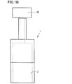
- FIGS. 1A to 1C are diagrams showing the shape of a nozzle in the blasting apparatus according to the present embodiment.
- the abrasive grains 1A are ejected from the nozzle 1 as shown in FIGS. 1A to 1C.
- the nozzle 1 includes an ejection port 2 (slit nozzle) having a straight (line segment) elongated hole shape (hereinafter referred to as “slit shape”).
- the length of the longitudinal side of the ejection port 2 (the width of the nozzle 1) is “w” as shown in FIG. 1C.
- a rotation mechanism 1B is provided, whereby the nozzle 1 can rotate around an axis in the direction in which the abrasive grains 1A are ejected (around the vertical axis in FIGS. 1A and 1B).
- the arrangement angle of the nozzle 1 is adjusted according to the shape of the part to be processed.
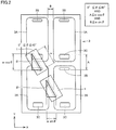
- FIG. 2 is a diagram for explaining the nozzle arrangement angle in the blasting apparatus according to the present embodiment.
- the glass substrate 3 is processed using the nozzle 1. From the glass substrate 3, glass plates corresponding to four products are cut out. That is, the glass substrate 3 has an outer edge 3A and openings 3B and 3C corresponding to four products.
- the nozzle 1 is movable in the X-axis direction (short direction of four products) and the Y-axis direction (long direction of four products).
- the longitudinal direction (width direction) of the slit-shaped injection port 2 is inclined by a predetermined angle (for example, ⁇ (0 ° to 45 °)) with respect to the movement direction (for example, the Y-axis direction) of the nozzle 1 and
- the nozzle 1 is arranged so that the projection of the injection port 2 includes the part to be processed. Note that the angle of the nozzle is not changed during blasting.
- the conditions of 0 ° ⁇ ⁇ ⁇ 45 °, A ⁇ w ⁇ cos ⁇ , and B ⁇ w ⁇ sin ⁇ are satisfied.
- a plurality (two) of nozzles 1 are arranged in accordance with the product pitch (center-to-center distance), and blasting is performed simultaneously on portions (product regions) corresponding to each product.
- a plurality (two in this case) of nozzles 1 are moved from one end of the glass substrate 3 to the other along the boundaries between the product areas corresponding to the plurality of products on the glass plate.
- Each nozzle 1 is arranged so that the injection port 2 of each nozzle 1 includes a processed portion in plan view.
- All the nozzles 1 are moved along one or more rounds of the product shape to process the glass plate.
- the glass substrate 3 is turned upside down and the above-mentioned from the second surface side of the glass substrate 3
- the steps (1) and (2) are appropriately performed to cut the glass plate.
- the steps (1) and (2) may be appropriately performed on only one of the first surface and the second surface of the glass substrate 3 to cut the glass plate.
- the processing speed by the nozzle 1 is adjusted suitably, you may make it different in a longitudinal direction and a transversal direction, and you may make it differ by a linear part and a corner
- the maximum value of the width (w) of the nozzle 2 of the nozzle 1 is preferably about 100 mm or less, more preferably about 75 mm or less, and further preferably about 50 mm or less. It is preferable that the minimum value of the width (w) is not less than a distance (for example, 10 mm) between adjacent product outlines.
- the angle ⁇ is preferably about 0 ° to 45 °, more preferably about 5 ° to 20 °, and still more preferably about 7 ° to 15 °.
- the distance including the outer edge of the adjacent product in the short direction and including all the small-shaped processed parts around it is L1
- the outer edge of the adjacent product in the longitudinal direction is included.
- the width (w) of the injection port 2 is w ⁇ (L1 2 + L2 2 ) (1/2) and the outer edge 3A in the longitudinal direction
- a film 30 having durability against grinding abrasive grains is provided on the surface of the processed portion of the glass substrate 3, and the condenser lens 20.
- the film 30 may be irradiated with the laser beam 10 that has been passed through to provide an opening in the film 30, and blasting may be performed by spraying abrasive grains onto the exposed glass substrate 3.
- the film 30 is pasted on the glass substrate 3 using the adhesive 40.
- the pressure-sensitive adhesive 40 is colored in a color that absorbs the laser light (that is, colored with a highly absorbing pigment in the ultraviolet to near-infrared wavelength band (such as black)). Thereby, you may remove the film 30 and the adhesive 40 on a cutting line using the laser beam 10 absorbed.
- a resist film may be formed by applying and drying a resist solution on a portion other than the processed portion of the glass substrate 3 using screen printing or inkjet.
- This resist film preferably has durability against grinding abrasive grains used in blasting.
- the resist film may not be colored because laser light is not used.
- the glass as the workpiece may be chemically tempered glass or air-cooled tempered glass.
- Examples of the material of the workpiece include ceramics such as silicon carbide (SiC, ceramics), sapphire (Al 2 O 3 ), sapphire glass, quartz (SiO 2 , quartz), quartz glass, heat-resistant glass, and alumina.
- ceramics such as silicon carbide (SiC, ceramics), sapphire (Al 2 O 3 ), sapphire glass, quartz (SiO 2 , quartz), quartz glass, heat-resistant glass, and alumina.
- Processing time is shortened (blasting speed is improved).
- COO Cost Of Ownership
- the processing time for the same range is shortened compared to the case of using a pen-shaped nozzle. This improves the life of the nozzle 1. 3.
- the same nozzle 1 can be used to cut glass plates having different product pitches and cutting line pitches. Specifically, by changing the angle of the nozzle 1 and the mounting pitch of the nozzle 1, the same nozzle 1 can cope with changes in different product pitches, different cutting line pitches, the number of cutting lines, and the like.
- 1,100 nozzle 1,100 nozzle, 1A grinding abrasive, 1B rotating mechanism, 2 injection port, 3 glass plate, 3A outer edge, 3B, 3C opening, 10 laser light, 20 condenser lens, 30 film, 40 adhesive.
Landscapes
- Engineering & Computer Science (AREA)
- Mechanical Engineering (AREA)
- Physics & Mathematics (AREA)
- Optics & Photonics (AREA)
- Plasma & Fusion (AREA)
- Surface Treatment Of Glass (AREA)
- Laser Beam Processing (AREA)
- Re-Forming, After-Treatment, Cutting And Transporting Of Glass Products (AREA)
Abstract
ブラスト加工装置は、被加工物上を移動しながら上記被加工物に対して研削砥粒(1A)を噴射することによって、上記被加工物における被加工部においてブラスト加工を行なうブラスト加工装置であって、上記研削砥粒を噴射するノズル(1)と、ノズル(1)に設けられ、スリット形状を有する噴射口(2)と、上記研削砥粒が噴出される方向の軸まわりに上記ノズルを回転させる回転機構(1B)とを備える。
Description
本発明は、ブラスト加工装置およびブラスト加工による製品製造方法に関する。
スマートフォン等に使用されているカバーガラスとして、化学強化ガラスが使用される。このカバーガラスは、複数枚のカバーガラスのサイズを割り当てられた大型ガラスを切断することによって製造される。化学強化ガラスには、切断前に化学強化処理を行なうシートタイプと、切断後に化学強化処理を行なうセルタイプとがある。化学強化したガラスは、表面に圧縮応力がかかっており切断しにくく、切断品質が悪く歩留まり率も悪いため、スマートフォンに使用するカバーガラスとして、シートタイプは一般的に好まれず、未強化の状態で切断するセルタイプが主流である。大型ガラスの切断は、CNCミーリングやペン形状ノズルを使用するブラスト加工法によって行なわれる。また、ダイシングソーやダイヤモンドスクライバーなどを用いて切断される場合もある。
ブラスト加工法によれば、レーザ加工法に比べて装置の初期投資額を抑えることができる。一方、ブラスト加工法の加工効率は、レーザ加工法よりも低い。ブラスト加工法の加工効率を向上させるために、ブラスト加工機に複数のペン形状ノズルを取り付けて複数枚の強化ガラスを同時に加工することも行なわれている。
ブラスト加工によって強化ガラスを切断する場合には、ガラス板の両面にフィルム(レジストフィルム)を貼り付け、加工ライン(ガラスが切断される切断線)上のフィルムをカッター、露光・現像、レーザ光などによって除去した後にブラスト加工を行なう。
ブラスト加工法のノズル毎の加工はレーザ加工に比べて遅い。ペン形状ノズルによって丸穴を加工する場合は、ペン形状ノズルを細かく周回(移動)させなければならない。たとえば、図6に示すように、ペン形状のノズル100を用いてガラス基板3に対して外縁3Aと開口3B,3Cを形成するための加工を施す場合、図6中の矢印に示す矢印の方向にノズルを移動させる必要がある。ノズルの移動距離が長いため、加工効率は低い。
ノズルの噴射口とガラス板とを同等の寸法形状すれば、ガラス板上に設けられた複数の加工部を同時に加工することができる。この場合、ペン形状ノズルに比べて加工範囲が広いため、研削砥粒の噴射圧力が分散し、結果として加工速度が遅くなる場合がある。
ノズルの噴射口と加工部分とが近接すると、研削砥粒が反射する。噴射口から噴射される研削砥粒と反射された研削砥粒が衝突するため、砥粒の安定した噴射が難しくなり、加工速度が低下する(加工時間が増大する)。また、研削砥粒の回収率(使用した研削砥粒を再使用できる割合)が低下する。特に、ノズルの中心軸がガラス板に対して直角である場合、研削砥粒が反射することに起因する上述の問題が発生する。また、ノズルの送り速度を遅くすると、反射された研削砥粒による影響が大きくなる。
紫外~近赤外の波長のレーザ光を用いて切断線上のフィルムに開口パターンを形成する場合、表裏同時加工が可能となるため、表裏の位置ずれがなくカッターや露光・現像と比べて加工時間が短い。しかし、レーザ加工だけではフィルムの粘着層が完全には除去されないため、フィルムの粘着層がガラス上面に残り、残った粘着剤が後工程において悪影響を与える場合がある。
本発明は、上記のような問題に鑑みてなされたものである。
本発明に係るブラスト加工装置は、被加工物上を移動しながら上記被加工物に対して研削砥粒を噴射することによって、上記被加工物における被加工部においてブラスト加工を行なうブラスト加工装置であって、上記研削砥粒を噴射するノズルと、上記ノズルに設けられ、スリット形状を有する噴射口と、上記研削砥粒が噴出される方向の軸まわりに上記ノズルを回転させる回転機構とを備える。
1つの実施態様では、上記ブラスト加工装置において、上記スリット形状の長手方向を上記ノズルの移動方向に対して所定の角度だけ傾けるとともに、上記被加工物に対する上記噴射口の投影が上記被加工部を内包するように上記ノズルを配置することが可能である。
1つの実施態様では、上記ブラスト加工装置において、上記被加工部に製品の外縁を形成することが可能である。
1つの実施態様では、上記ブラスト加工装置において、上記被加工部に貫通穴を形成することが可能である。
本発明に係るブラスト加工による製品製造方法は、被加工物上を移動しながら上記被加工物に対して研削砥粒を噴射することによって、上記被加工物における被加工部においてブラスト加工を行なう製品製造方法であって、上記研削砥粒が噴出される方向の軸まわりにノズルを回転させて上記ノズルの方向を調整する工程と、上記ノズルに設けられたスリット形状を有する噴射口から上記研削砥粒を噴射する工程とを備える。
1つの実施態様では、上記ブラスト加工による製品製造方法において、上記ノズルの方向を調整する工程は、上記スリット形状の長手方向を上記ノズルの移動方向に対して所定の角度だけ傾けるとともに、上記被加工物に対する上記噴射口の投影が上記被加工部を内包するように上記ノズルを配置することを含む。
1つの実施態様では、上記ブラスト加工による製品製造方法において、上記噴射口から上記研削砥粒を噴射する工程は、上記被加工部が有する第1面と、上記第1面の反対面の第2面とに対して順次ブラスト加工を行なうことによって、貫通穴を形成することを含む。
1つの実施態様では、上記ブラスト加工による製品製造方法において、上記被加工物は複数の製品にそれぞれ対応する複数の製品領域を有し、上記被加工部は上記製品領域の外縁に対応する。
1つの実施態様では、上記ブラスト加工による製品製造方法において、上記被加工物は複数の製品にそれぞれ対応する複数の製品領域を有し、上記被加工部は上記製品領域に含まれる貫通穴に対応する。
1つの実施態様では、上記ブラスト加工による製品製造方法は、上記研削砥粒に対する耐久性を有するレジスト膜を上記被加工部の表面に設ける工程と、上記レジスト膜に開口を設け、上記被加工部を露出させる工程とをさらに備え、上記被加工部を露出させる工程では、上記レジスト膜にレーザ光を照射して該レジスト膜に上記開口を設けること、または、上記被加工部における上記被加工部以外の部分に上記レジスト膜を付着させることによって上記被加工部において上記開口を設けることを実行する。
1つの実施態様では、上記ブラスト加工による製品製造方法は、上記被加工部の表面にフィルムを設ける工程と、上記被加工物に設けられた上記フィルムにレーザ光を照射して該フィルムに開口を設け、上記被加工部を露出させる工程とをさらに備え、上記フィルムは上記研削砥粒に対する耐久性を有する。
1つの実施態様では、上記ブラスト加工による製品製造方法において、上記被加工部の表面に上記フィルムを設ける工程は、粘着剤を用いて上記フィルムを上記被加工部上に貼り付けることを含み、上記粘着剤は、上記レーザ光が吸収される色に着色されている。
本発明によれば、ブラスト加工機による加工時間が短縮される。また、ブラスト加工に伴うコストを低減することができる。また、異なるパターンに対して同じノズルを使用してブラスト加工を行なうことができる。
以下に、本発明の実施の形態について説明する。なお、同一または相当する部分に同一の参照符号を付し、その説明を繰返さない場合がある。
なお、以下に説明する実施の形態において、個数、量などに言及する場合、特に記載がある場合を除き、本発明の範囲は必ずしもその個数、量などに限定されない。また、以下の実施の形態において、各々の構成要素は、特に記載がある場合を除き、本発明にとって必ずしも必須のものではない。
本実施の形態に係るブラスト加工装置は、ガラス板などの被加工物上を移動しながら被加工物に対して研削砥粒を噴射することによってブラスト加工を行なうブラスト加工装置である。
図1A~図1Cは、本実施の形態に係るブラスト加工装置におけるノズルの形状を示す図である。研削砥粒1Aは、図1A~図1Cに示すをノズル1から噴射される。ノズル1は、直線(線分)状の長穴形状(以下、「スリット形状」という。)を有する噴射口2(スリットノズル)を含む。噴射口2の長手辺の長さ(ノズル1の幅)は、図1Cに示すように「w」である。
回転機構1Bが設けられ、これにより、ノズル1は、研削砥粒1Aが噴出される方向の軸まわり(図1A、図1Bにおける上下方向軸まわり)に回転可能である。被加工部の形状に応じてノズル1の配置角度が調整される。
図2は、本実施の形態に係るブラスト加工装置におけるノズルの配置角度を説明するための図である。図2の例では、ノズル1を用いてガラス基板3に対して加工を施す。ガラス基板3からは、4つの製品に対応するガラス板が切り出される。すなわち、ガラス基板3には、4つの製品に対応する外縁3A、および開口3B,3Cがある。
図2において、ノズル1はX軸方向(4つの製品の短手方向)およびY軸方向(4つの製品の長手方向)に移動可能である。スリット形状の噴射口2の長手方向(幅方向)をノズル1の移動方向(たとえばY軸方向)に対して所定の角度(たとえばθ(0°~45°))だけ傾けるとともに、被加工物に対する噴射口2の投影が被加工部を内包するようにノズル1を配置する。なお、ブラスト加工中はノズルの角度を変更しない。
図2の例では、0°≦θ≦45°、かつ、A≦w・cosθ、かつ、B≦w・sinθの条件を満たす。これにより、ノズル1がX軸方向に移動するときには、隣り合う製品の開口3B,3Cに対応する部分を同時に加工することができる。また、ノズル1がY軸方向に移動するときには、隣り合う製品の外縁3Aに対応する部分を同時に加工することができる。
たとえば、図3に示す「A」、「B」の距離が図4に示す「A´」、「B´」に変更される場合、ノズル1を回転させる(図4では図3に対して反時計まわりに回転している。)。
なお、図2の例では、製品のピッチ(中心間距離)に合わせて複数(2つ)のノズル1を配置して各製品に相当する部分(製品領域)に対して同時にブラスト加工を行なう。
ノズル1が行なうブラスト加工については、下記(1)~(3)を想定している。
(1) 下記(1-1)と(1-2)とを択一的に使用する。
(1) 下記(1-1)と(1-2)とを択一的に使用する。
(1-1) ガラス板における複数の製品にそれぞれ相当する製品領域どうしの境界に沿って、複数(ここでは2つ)のノズル1を、ガラス基板3の端から端まで移動させる。各々のノズル1の噴射口2が平面視において被加工部を含むように各ノズル1を配置する。
(1-2) 全てのノズル1を、製品形状の1周分以上に沿って移動させて、ガラス板を加工する。
(2) 複数の製品領域間に2本以上の切断線(外縁3A)が設けられる場合には、それらの切断線においてガラス基板3を同時に加工する。円形形状、矩形形状などを有する開口3B,3C(たとえば、スマートフォンにおけるスピーカー用、ボタン用など)が外縁3Aの近傍に設けられる場合には、開口3B,3Cを外縁3Aと同時に加工する。
(3) ガラス基板3の第1面における全ての加工部分の加工深さが板厚の2/3程度になった後に、ガラス基板3を表裏反転させてガラス基板3の第2面側から上記(1)、(2)の工程を適宜行ない、ガラス板を切断する。ガラス基板3の第1面または第2面のいずれか一方のみに上記(1)、(2)の工程を適宜行ない、ガラス板を切断してもよい。
なお、ノズル1による加工速度は、適宜調整されるが、長手方向と短手方向とで異なるものにしてもよいし、直線部と角部(コーナー部)とで異なるものにしてもよい。
ノズル1の噴射口2の幅(w)の最大値は好ましくは100mm以下程度、より好ましくは75mm以下程度、さらに好ましくは50mm以下程度である。幅(w)の最小値は、隣り合う製品外形どうしの距離(たとえば10mm)以上であることが好ましい。
角度θは、好ましくは0°以上45°以下程度、より好ましくは5°以上20°以下程度、さらに好ましくは7°以上15°以下程度である。
典型的な例では、長方形状の製品において、隣り合う製品の短手方向の外縁を含み、かつその周囲にある小形状加工部を全て含む距離をL1、隣り合う製品の長手方向の外縁を含み、かつその周囲にある小形状加工部を全て含む距離をL2としたとき、噴射口2の幅(w)は、w≧(L12+L22)(1/2)、長手方向の外縁3Aと噴射口の幅方向とのなす角度は、θ(rad)=arctan(L2/L1)である。
ところで、本実施の形態に係るブラスト加工による製品製造方法において、図5に示すように、ガラス基板3の被加工部の表面に研削砥粒に対する耐久性を有するフィルム30を設け、集光レンズ20を通過させたレーザ光10をフィルム30に照射してフィルム30に開口を設け、露出したガラス基板3に研削砥粒を噴射することでブラスト加工を行なうようにしてもよい。フィルム30は、粘着剤40を用いてをガラス基板3上に貼り付けられる。粘着剤40は、上記レーザ光が吸収される色(すなわち、紫外~近赤外の波長帯において吸収性の高い色素で着色(黒色等))に着色されている。これにより、吸収されるレーザ光10を使用して、切断線上におけるフィルム30および粘着剤40を除去してもよい。
上記の工程の変形例として、スクリーン印刷、インクジェットを使用してガラス基板3の被加工部以外にレジスト液を塗布して乾燥させることによって、レジスト膜を形成してもよい。このレジスト膜は、ブラスト加工において使用される研削砥粒に対する耐久性を有することが好ましい。スクリーン印刷やインクジェットによって被加工部以外にレジスト膜を形成する場合、レーザ光を使用しないためレジスト膜は着色していなくてもよい。
なお、被加工物としてのガラスは化学強化ガラスであってもよいし、風冷強化ガラスであってもよい。
被加工物の材料としては、炭化ケイ素(SiC、セラミックス)、サファイア(Al2O3)、サファイアガラス、石英(SiO2、水晶)、石英ガラス、耐熱ガラス、アルミナなどのセラミックスなどが考えられる。
次に、本実施の形態に係るブラスト加工装置の作用効果(下記、3点)について説明する。
1.加工時間が短縮される(ブラスト加工速度が向上する)。
(1)ノズルの加工範囲内において、製品間に2本以上の切断線や開口が形成される部分がある場合には、同時に加工することによって加工時間を短縮(たとえば1/2以下程度に)することができる。
(2)切断線に対してノズルの幅方向が斜めとなる角度を設定する。加えて、速度を上げてノズルを移動させる。これらによって、反射された研削砥粒に起因する、噴射口2から供給された研削砥粒の粉砕と加工速度の低下とを防止することができる。
2.COO(Cost Of Ownership)が低減する。
(1)ペン形状ノズルを使用する場合に比較して、ノズル1が単位長さだけ移動することによって加工できる領域が増加する。したがって、単位時間当たりの生産量が向上する。
(2)ガラス板と同等の寸法形状を持つ噴射口を有するノズルを使用する場合に比較して、ノズル1が単位長さだけ移動することによって使用する研削砥粒の量が低減する。したがって、同じ面積のガラス板を加工する際の研削砥粒の消費量が低減する。
(3)研削砥粒の粉砕が抑制されるので、研削砥粒の回収率が向上する。
(4)上記(1)と同じ理由から、ペン形状ノズルを使用する場合に比較して、同じ範囲に対する加工時間が短縮する。このことにより、ノズル1の寿命が向上する。
3.同じノズル1を使用して、異なる製品ピッチや切断線ピッチを有するガラス板を切断できる。具体的には、ノズル1の角度や、ノズル1の取り付けピッチを変更することにより、異なる製品ピッチ,異なる切断線ピッチ,切断線数の変更などに対して、同じノズル1で対応できる。
1.加工時間が短縮される(ブラスト加工速度が向上する)。
(1)ノズルの加工範囲内において、製品間に2本以上の切断線や開口が形成される部分がある場合には、同時に加工することによって加工時間を短縮(たとえば1/2以下程度に)することができる。
(2)切断線に対してノズルの幅方向が斜めとなる角度を設定する。加えて、速度を上げてノズルを移動させる。これらによって、反射された研削砥粒に起因する、噴射口2から供給された研削砥粒の粉砕と加工速度の低下とを防止することができる。
2.COO(Cost Of Ownership)が低減する。
(1)ペン形状ノズルを使用する場合に比較して、ノズル1が単位長さだけ移動することによって加工できる領域が増加する。したがって、単位時間当たりの生産量が向上する。
(2)ガラス板と同等の寸法形状を持つ噴射口を有するノズルを使用する場合に比較して、ノズル1が単位長さだけ移動することによって使用する研削砥粒の量が低減する。したがって、同じ面積のガラス板を加工する際の研削砥粒の消費量が低減する。
(3)研削砥粒の粉砕が抑制されるので、研削砥粒の回収率が向上する。
(4)上記(1)と同じ理由から、ペン形状ノズルを使用する場合に比較して、同じ範囲に対する加工時間が短縮する。このことにより、ノズル1の寿命が向上する。
3.同じノズル1を使用して、異なる製品ピッチや切断線ピッチを有するガラス板を切断できる。具体的には、ノズル1の角度や、ノズル1の取り付けピッチを変更することにより、異なる製品ピッチ,異なる切断線ピッチ,切断線数の変更などに対して、同じノズル1で対応できる。
以上、本発明の実施の形態について説明したが、今回開示された実施の形態はすべての点で例示であって制限的なものではないと考えられるべきである。本発明の範囲は請求の範囲によって示され、請求の範囲と均等の意味および範囲内でのすべての変更が含まれることが意図される。
1,100 ノズル、1A 研削砥粒、1B 回転機構、2 噴射口、3 ガラス板、3A 外縁、3B,3C 開口、10 レーザ光、20 集光レンズ、30 フィルム、40 粘着剤。
Claims (12)
- 被加工物上を移動しながら前記被加工物に対して研削砥粒を噴射することによって、前記被加工物における被加工部においてブラスト加工を行なうブラスト加工装置であって、
前記研削砥粒を噴射するノズルと、
前記ノズルに設けられ、スリット形状を有する噴射口と、
前記研削砥粒が噴出される方向の軸まわりに前記ノズルを回転させる回転機構とを備えた、ブラスト加工装置。 - 前記スリット形状の長手方向を前記ノズルの移動方向に対して所定の角度だけ傾けるとともに、前記被加工物に対する前記噴射口の投影が前記被加工部を内包するように前記ノズルを配置することが可能である、請求項1に記載のブラスト加工装置。
- 前記被加工部に製品の外縁を形成することが可能である、請求項1または請求項2に記載のブラスト加工装置。
- 前記被加工部に貫通穴を形成することが可能である、請求項1から請求項3のいずれかに記載のブラスト加工装置。
- 被加工物上を移動しながら前記被加工物に対して研削砥粒を噴射することによって、前記被加工物における被加工部においてブラスト加工を行なう製品製造方法であって、
前記研削砥粒が噴出される方向の軸まわりにノズルを回転させて前記ノズルの方向を調整する工程と、
前記ノズルに設けられたスリット形状を有する噴射口から前記研削砥粒を噴射する工程とを備えた、ブラスト加工による製品製造方法。 - 前記ノズルの方向を調整する工程は、前記スリット形状の長手方向を前記ノズルの移動方向に対して所定の角度だけ傾けるとともに、前記被加工物に対する前記噴射口の投影が前記被加工部を内包するように前記ノズルを配置することを含む、請求項5に記載のブラスト加工による製品製造方法。
- 前記噴射口から前記研削砥粒を噴射する工程は、前記被加工部が有する第1面と、前記第1面の反対面の第2面とに対して順次ブラスト加工を行なうことによって、貫通穴を形成することを含む、請求項5または請求項6に記載のブラスト加工による製品製造方法。
- 前記被加工物は複数の製品にそれぞれ対応する複数の製品領域を有し、
前記被加工部は前記製品領域の外縁に対応する、請求項5から請求項7のいずれかに記載のブラスト加工による製品製造方法。 - 前記被加工物は複数の製品にそれぞれ対応する複数の製品領域を有し、
前記被加工部は前記製品領域に含まれる貫通穴に対応する、請求項5から請求項7のいずれかに記載のブラスト加工による製品製造方法。 - 前記研削砥粒に対する耐久性を有するレジスト膜を前記被加工部の表面に設ける工程と、
前記レジスト膜に開口を設け、前記被加工部を露出させる工程とをさらに備え、
前記被加工部を露出させる工程では、前記レジスト膜にレーザ光を照射して該レジスト膜に前記開口を設けること、または、前記被加工部における前記被加工部以外の部分に前記レジスト膜を付着させることによって前記被加工部において前記開口を設けることのいずれかを実行する、請求項5から請求項9のいずれかに記載のブラスト加工による製品製造方法。 - 前記被加工部の表面にフィルムを設ける工程と、
前記被加工物に設けられた前記フィルムにレーザ光を照射して該フィルムに開口を設け、前記被加工部を露出させる工程とをさらに備え、
前記フィルムは前記研削砥粒に対する耐久性を有する、請求項5から請求項9のいずれかに記載のブラスト加工による製品製造方法。 - 前記被加工部の表面に前記フィルムを設ける工程は、粘着剤を用いて前記フィルムを前記被加工部上に貼り付けることを含み、
前記粘着剤は、前記レーザ光が吸収される色に着色されている、請求項11に記載のブラスト加工による製品製造方法。
Priority Applications (1)
| Application Number | Priority Date | Filing Date | Title |
|---|---|---|---|
| KR1020187000528A KR20180028445A (ko) | 2015-07-09 | 2016-06-07 | 블라스트 가공 장치 및 블라스트 가공에 의한 제품 제조 방법 |
Applications Claiming Priority (2)
| Application Number | Priority Date | Filing Date | Title |
|---|---|---|---|
| JP2015-137747 | 2015-07-09 | ||
| JP2015137747A JP2017019036A (ja) | 2015-07-09 | 2015-07-09 | ブラスト加工装置およびブラスト加工による製品製造方法 |
Publications (1)
| Publication Number | Publication Date |
|---|---|
| WO2017006683A1 true WO2017006683A1 (ja) | 2017-01-12 |
Family
ID=57685385
Family Applications (1)
| Application Number | Title | Priority Date | Filing Date |
|---|---|---|---|
| PCT/JP2016/066854 Ceased WO2017006683A1 (ja) | 2015-07-09 | 2016-06-07 | ブラスト加工装置およびブラスト加工による製品製造方法 |
Country Status (3)
| Country | Link |
|---|---|
| JP (1) | JP2017019036A (ja) |
| KR (1) | KR20180028445A (ja) |
| WO (1) | WO2017006683A1 (ja) |
Cited By (1)
| Publication number | Priority date | Publication date | Assignee | Title |
|---|---|---|---|---|
| CN108436787A (zh) * | 2018-04-11 | 2018-08-24 | 佛山市穗远恒科建材有限公司 | 一种花纹玻璃喷砂成形的装置及方法 |
Families Citing this family (1)
| Publication number | Priority date | Publication date | Assignee | Title |
|---|---|---|---|---|
| WO2017188168A1 (ja) * | 2016-04-28 | 2017-11-02 | 日本ゼオン株式会社 | 光学フィルムの製造方法 |
Citations (6)
| Publication number | Priority date | Publication date | Assignee | Title |
|---|---|---|---|---|
| JPS63237869A (ja) * | 1987-03-26 | 1988-10-04 | Fuji Seiki Seizosho:Kk | 噴射ガン |
| JP2001506925A (ja) * | 1996-12-23 | 2001-05-29 | エフエスアイ インターナショナル インコーポレーティッド | 回転可能で移動可能な噴霧ノズル |
| JP2003249740A (ja) * | 2002-02-22 | 2003-09-05 | Sumitomo Heavy Ind Ltd | レーザ加工方法及び有孔部材 |
| JP2010082792A (ja) * | 2008-10-02 | 2010-04-15 | Disco Abrasive Syst Ltd | ウォータジェット加工方法 |
| JP2012000711A (ja) * | 2010-06-16 | 2012-01-05 | Egawa Seisakusho Kk | サンドブラストによる刻印用メタルマスク |
| JP2012045651A (ja) * | 2010-08-25 | 2012-03-08 | Fuji Seisakusho:Kk | サンドブラストによる切削加工方法 |
-
2015
- 2015-07-09 JP JP2015137747A patent/JP2017019036A/ja active Pending
-
2016
- 2016-06-07 WO PCT/JP2016/066854 patent/WO2017006683A1/ja not_active Ceased
- 2016-06-07 KR KR1020187000528A patent/KR20180028445A/ko not_active Ceased
Patent Citations (6)
| Publication number | Priority date | Publication date | Assignee | Title |
|---|---|---|---|---|
| JPS63237869A (ja) * | 1987-03-26 | 1988-10-04 | Fuji Seiki Seizosho:Kk | 噴射ガン |
| JP2001506925A (ja) * | 1996-12-23 | 2001-05-29 | エフエスアイ インターナショナル インコーポレーティッド | 回転可能で移動可能な噴霧ノズル |
| JP2003249740A (ja) * | 2002-02-22 | 2003-09-05 | Sumitomo Heavy Ind Ltd | レーザ加工方法及び有孔部材 |
| JP2010082792A (ja) * | 2008-10-02 | 2010-04-15 | Disco Abrasive Syst Ltd | ウォータジェット加工方法 |
| JP2012000711A (ja) * | 2010-06-16 | 2012-01-05 | Egawa Seisakusho Kk | サンドブラストによる刻印用メタルマスク |
| JP2012045651A (ja) * | 2010-08-25 | 2012-03-08 | Fuji Seisakusho:Kk | サンドブラストによる切削加工方法 |
Cited By (1)
| Publication number | Priority date | Publication date | Assignee | Title |
|---|---|---|---|---|
| CN108436787A (zh) * | 2018-04-11 | 2018-08-24 | 佛山市穗远恒科建材有限公司 | 一种花纹玻璃喷砂成形的装置及方法 |
Also Published As
| Publication number | Publication date |
|---|---|
| KR20180028445A (ko) | 2018-03-16 |
| JP2017019036A (ja) | 2017-01-26 |
Similar Documents
| Publication | Publication Date | Title |
|---|---|---|
| US11396471B2 (en) | Method for machining the edges of glass elements and glass element machined according to the method | |
| KR101889523B1 (ko) | 샌드블라스팅에 의한 절삭 방법 | |
| KR102210945B1 (ko) | 웨이퍼의 가공 방법 | |
| US9649775B2 (en) | Workpiece dividing method | |
| JP5881464B2 (ja) | ウェーハのレーザー加工方法 | |
| TWI600077B (zh) | Wafer cutting method | |
| JP6483974B2 (ja) | 加工対象物切断方法 | |
| KR20170021731A (ko) | 웨이퍼의 가공 방법 | |
| KR20150130226A (ko) | 웨이퍼 가공 방법 | |
| JP4750427B2 (ja) | ウエーハのレーザー加工方法 | |
| KR102345170B1 (ko) | 기판의 가공방법 | |
| KR102286476B1 (ko) | 유리 기판 절단 방법 및 도광판 제조 방법 | |
| JP2000247671A (ja) | ガラスの分断方法 | |
| JP2014054713A (ja) | ウェーハの加工方法 | |
| CN109352184B (zh) | 硅基晶圆的分束激光切割方法 | |
| WO2017006683A1 (ja) | ブラスト加工装置およびブラスト加工による製品製造方法 | |
| CN109352185B (zh) | 碳化硅基晶圆的分束激光切割方法 | |
| US20210394327A1 (en) | Systems and methods for forming multi-section displays | |
| JP2013054128A (ja) | 塗布装置及び塗布方法 | |
| CN107850554A (zh) | 相对于气流的镭射扫描定序及方向 | |
| CN109848662B (zh) | 一种可调控结构色微沟槽阵列的加工方法 | |
| KR100849439B1 (ko) | 노광장비의 스텝퍼척 제조방법 | |
| KR102012691B1 (ko) | 레이저와 분말을 이용한 3차원 형상 제조방법 | |
| KR100648898B1 (ko) | 2개의 레이저를 이용한 웨이퍼의 분할방법 및 장치 | |
| JP6791585B2 (ja) | ウェーハの加工方法 |
Legal Events
| Date | Code | Title | Description |
|---|---|---|---|
| 121 | Ep: the epo has been informed by wipo that ep was designated in this application |
Ref document number: 16821154 Country of ref document: EP Kind code of ref document: A1 |
|
| ENP | Entry into the national phase |
Ref document number: 20187000528 Country of ref document: KR Kind code of ref document: A |
|
| NENP | Non-entry into the national phase |
Ref country code: DE |
|
| 122 | Ep: pct application non-entry in european phase |
Ref document number: 16821154 Country of ref document: EP Kind code of ref document: A1 |