WO2017006532A1 - 保護制御装置 - Google Patents
保護制御装置 Download PDFInfo
- Publication number
- WO2017006532A1 WO2017006532A1 PCT/JP2016/003045 JP2016003045W WO2017006532A1 WO 2017006532 A1 WO2017006532 A1 WO 2017006532A1 JP 2016003045 W JP2016003045 W JP 2016003045W WO 2017006532 A1 WO2017006532 A1 WO 2017006532A1
- Authority
- WO
- WIPO (PCT)
- Prior art keywords
- vehicle
- collision position
- unit
- collision
- secondary collision
- Prior art date
- Legal status (The legal status is an assumption and is not a legal conclusion. Google has not performed a legal analysis and makes no representation as to the accuracy of the status listed.)
- Ceased
Links
Images


Classifications
-
- B—PERFORMING OPERATIONS; TRANSPORTING
- B60—VEHICLES IN GENERAL
- B60R—VEHICLES, VEHICLE FITTINGS, OR VEHICLE PARTS, NOT OTHERWISE PROVIDED FOR
- B60R21/00—Arrangements or fittings on vehicles for protecting or preventing injuries to occupants or pedestrians in case of accidents or other traffic risks
- B60R21/01—Electrical circuits for triggering passive safety arrangements, e.g. airbags, safety belt tighteners, in case of vehicle accidents or impending vehicle accidents
- B60R21/013—Electrical circuits for triggering passive safety arrangements, e.g. airbags, safety belt tighteners, in case of vehicle accidents or impending vehicle accidents including means for detecting collisions, impending collisions or roll-over
- B60R21/0134—Electrical circuits for triggering passive safety arrangements, e.g. airbags, safety belt tighteners, in case of vehicle accidents or impending vehicle accidents including means for detecting collisions, impending collisions or roll-over responsive to imminent contact with an obstacle, e.g. using radar systems
-
- B—PERFORMING OPERATIONS; TRANSPORTING
- B60—VEHICLES IN GENERAL
- B60R—VEHICLES, VEHICLE FITTINGS, OR VEHICLE PARTS, NOT OTHERWISE PROVIDED FOR
- B60R19/00—Wheel guards; Radiator guards, e.g. grilles; Obstruction removers; Fittings damping bouncing force in collisions
- B60R19/02—Bumpers, i.e. impact receiving or absorbing members for protecting vehicles or fending off blows from other vehicles or objects
- B60R19/18—Bumpers, i.e. impact receiving or absorbing members for protecting vehicles or fending off blows from other vehicles or objects characterised by the cross-section; Means within the bumper to absorb impact
- B60R19/20—Bumpers, i.e. impact receiving or absorbing members for protecting vehicles or fending off blows from other vehicles or objects characterised by the cross-section; Means within the bumper to absorb impact containing mainly gas or liquid, e.g. inflatable
- B60R19/205—Bumpers, i.e. impact receiving or absorbing members for protecting vehicles or fending off blows from other vehicles or objects characterised by the cross-section; Means within the bumper to absorb impact containing mainly gas or liquid, e.g. inflatable inflatable in the direction of an obstacle upon impending impact, e.g. using air bags
-
- B—PERFORMING OPERATIONS; TRANSPORTING
- B60—VEHICLES IN GENERAL
- B60R—VEHICLES, VEHICLE FITTINGS, OR VEHICLE PARTS, NOT OTHERWISE PROVIDED FOR
- B60R21/00—Arrangements or fittings on vehicles for protecting or preventing injuries to occupants or pedestrians in case of accidents or other traffic risks
- B60R21/34—Protecting non-occupants of a vehicle, e.g. pedestrians
- B60R21/36—Protecting non-occupants of a vehicle, e.g. pedestrians using airbags
-
- B—PERFORMING OPERATIONS; TRANSPORTING
- B60—VEHICLES IN GENERAL
- B60R—VEHICLES, VEHICLE FITTINGS, OR VEHICLE PARTS, NOT OTHERWISE PROVIDED FOR
- B60R21/00—Arrangements or fittings on vehicles for protecting or preventing injuries to occupants or pedestrians in case of accidents or other traffic risks
- B60R21/34—Protecting non-occupants of a vehicle, e.g. pedestrians
- B60R21/38—Protecting non-occupants of a vehicle, e.g. pedestrians using means for lifting bonnets
-
- B—PERFORMING OPERATIONS; TRANSPORTING
- B60—VEHICLES IN GENERAL
- B60R—VEHICLES, VEHICLE FITTINGS, OR VEHICLE PARTS, NOT OTHERWISE PROVIDED FOR
- B60R21/00—Arrangements or fittings on vehicles for protecting or preventing injuries to occupants or pedestrians in case of accidents or other traffic risks
- B60R21/01—Electrical circuits for triggering passive safety arrangements, e.g. airbags, safety belt tighteners, in case of vehicle accidents or impending vehicle accidents
- B60R2021/01013—Means for detecting collision, impending collision or roll-over
-
- B—PERFORMING OPERATIONS; TRANSPORTING
- B60—VEHICLES IN GENERAL
- B60R—VEHICLES, VEHICLE FITTINGS, OR VEHICLE PARTS, NOT OTHERWISE PROVIDED FOR
- B60R2300/00—Details of viewing arrangements using cameras and displays, specially adapted for use in a vehicle
- B60R2300/30—Details of viewing arrangements using cameras and displays, specially adapted for use in a vehicle characterised by the type of image processing
- B60R2300/301—Details of viewing arrangements using cameras and displays, specially adapted for use in a vehicle characterised by the type of image processing combining image information with other obstacle sensor information, e.g. using RADAR/LIDAR/SONAR sensors for estimating risk of collision
Definitions
- the present disclosure relates to a protection control device that controls the operation of a protection device for protecting a person who collides with a vehicle.
- a system for operating a protective device such as an airbag deployed in a predetermined area outside the vehicle when a primary collision with a pedestrian is detected Is known (for example, Patent Document 1). According to such a system, the impact given to a pedestrian by a secondary collision can be relieved.
- a pop-up hood device that lifts the rear of the hood in addition to a windshield, an airbag deployed in various areas such as a pillar portion, a cowl top, etc. is there.
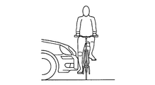
- a motorcycle and a two-wheeled vehicle such as a bicycle on which the occupant is riding collide with the vehicle
- the occupant of the two-wheeled moving body also falls to the vehicle side and has a secondary collision with the vehicle body.
- an occupant of a two-wheeled vehicle (referred to as a two-wheeled vehicle occupant) is also an object to be protected in the event of a collision with a vehicle, and these protection devices should be operated even when a collision with the two-wheeled vehicle is detected. It is.
- the vehicle (primarily colliding object) with which the vehicle collided is a two-wheeled vehicle
- the two-wheeled vehicle and its occupant are separated from each other, and the centroid position of the occupant of the two-wheeled vehicle is the pedestrian's centroid position. Due to the fact that the two-wheeled vehicle has a higher position than the pedestrian and the moving speed of the two-wheeled vehicle is larger than that of the pedestrian, the behavior of the two-wheeled vehicle occupant that has collided primarily with the vehicle And different.
- the two-wheeled vehicle occupant does not always fall into the area supported by the vehicle protection device. Moreover, it can be said that it is uneconomical to operate the protection device corresponding to the area where the motorcycle occupant does not collide. If the vehicle is provided with a plurality of protection devices having different regions on the outer surface of the vehicle as corresponding regions, a protection device corresponding to a region in which the two-wheeled vehicle occupant may collide secondarily among the plurality of protection devices. While operating, it is preferable not to operate the protection device corresponding to the area where the motorcycle occupant is unlikely to have a secondary collision.
- An object of the present invention is to provide a protection control device capable of suppressing the operation of the device.
- the protection control device is used in a vehicle on which at least one external protection device for protecting a two-wheeled vehicle occupant is mounted, and a predetermined detection area around the vehicle.
- a relative vector estimation unit that estimates a relative movement vector of the two-wheeled mobile body that has collided primary with the vehicle at the time of the primary collision based on the information acquired by the primary collision detection unit and the object recognition unit;
- a primary collision position specifying unit that obtains a primary collision position that is a relative position of the two-wheeled mobile body with respect to the vehicle at the time of the primary collision between the vehicle and the two-wheeled mobile body, and a relative vector estimation unit.
- a secondary collision position estimator for estimating a secondary collision position where the occupant of the two-wheeled mobile body collides with the vehicle based on the determined relative vector and the primary collision position acquired by the primary collision position specifying unit;
- An operation instruction unit that operates the external protection device, and an operation device selection unit that selects the external protection device corresponding to the secondary collision position estimated by the secondary collision position estimation unit as the external protection device to be operated.
- the operation instruction unit operates the external protection device selected by the operation device selection unit.
- the secondary collision position estimation unit estimates the secondary collision position of the occupant of the two-wheeled mobile body that has collided with the vehicle, and the motion device selection unit calculates the secondary collision position estimated by the secondary collision position estimation unit. Select the external protection device corresponding to. Then, the operation instruction unit operates the external protection device selected by the operation device selection unit.
- the external protection device corresponding to the secondary collision position estimated by the secondary collision position estimation unit corresponds to an external protection device corresponding to an area in which the occupant of the two-wheeled mobile body may have a secondary collision with the vehicle. That is, the protection control device selectively operates an external protection device corresponding to a region where a bicycle occupant who has collided with the vehicle may collide with the vehicle.
- the external protection device is not operated when there is no possibility that the occupant of the two-wheeled mobile body will have a secondary collision with the vehicle. Further, even if there is a possibility that the occupant of the two-wheeled mobile body has a secondary collision with the vehicle, the external protection device corresponding to the portion where there is no possibility of the secondary collision is not operated. Therefore, unnecessary operation of the external protection device that does not contribute to protection of the occupant of the two-wheeled mobile body can be suppressed while protecting the occupant of the two-wheeled mobile body.
- FIG. 1 It is a block diagram which shows an example of a schematic structure of a protective device control system. It is a conceptual diagram which shows the range used as a radar detection area and an imaging
- FIG. 1 is a diagram illustrating an example of a schematic configuration of a protection device control system 100 according to the present embodiment.
- This protection device control system 100 is mounted on a vehicle.
- the vehicle on which the protection device control system 100 is mounted is referred to as a host vehicle.
- the protection device control system 100 is a system for mainly protecting a passenger of a two-wheeled moving body such as a bicycle, a motorbike, a motorcycle or the like.
- a mode in which a bicycle that has jumped out from the left side of the host vehicle and the host vehicle collide at the front end (including the vicinity of the front end corner) of the host vehicle is exemplified.
- the protection device control system 100 as another aspect may be a system that assumes a case where the vehicle collides at a side portion or a rear end portion of the vehicle, for example. In that case, the protection device control system 100 exemplified here may be appropriately modified and used according to the assumed collision direction.
- the two-wheeled mobile body to be subjected to the collision is not limited to the bicycle on which the occupant is riding. It may be a two-wheeled moving body other than a bicycle, such as a motorcycle on which an occupant rides.
- the protection device control system 100 may be appropriately modified and used according to the assumed type of the two-wheeled mobile body.
- the protection device control system 100 in this embodiment includes a control device 1, a millimeter wave radar 2, a camera 3, a collision sensor 4, and an external protection device 5, as shown in FIG.
- the control device 1 and each of the millimeter wave radar 2, the camera 3, the collision sensor 4, and the external protection device 5 are connected via a communication network built in the vehicle.
- the control device 1 controls the operation of the external protection device 5 based on data provided from the millimeter wave radar 2, the camera 3, and the collision sensor 4.
- the control device 1 corresponds to a protection control device. The control device 1 will be described again after describing the millimeter wave radar 2, the camera 3, the collision sensor 4, and the external protection device 5.
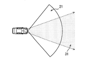
- the millimeter wave radar 2 transmits and receives millimeter waves or quasi-millimeter waves to acquire information about an object existing in a predetermined range (referred to as a radar detection area 21) in front of the host vehicle. Specifically, an object existing in the radar detection area 21 is detected, and the direction, distance, relative speed, type, and the like in which the detected object exists are estimated. The detection results of the millimeter wave radar 2 are sequentially provided to the control device 1.
- the type of the detected object may be identified based on the reception level of the reflected wave corresponding to the detected object.
- information such as the size of the detected object and the moving speed of the detected object obtained from the moving speed of the host vehicle and the detected relative speed may be used for identifying the type of the detected object. . Since a known method can be used as a method for specifying the type of detection object, detailed description thereof is omitted here.
- FIG. 2 conceptually shows the radar detection area 21.
- the radar detection area 21 is a range corresponding to the installation position, directivity, and maximum detection distance of the millimeter wave radar 2.
- the installation position and mounting posture of the millimeter wave radar 2 may be determined as appropriate so as to form a desired radar detection area 21.
- the front grille and the front are arranged so that the central direction of directivity faces the front of the vehicle. What is necessary is just to be provided in a bumper etc.
- the horizontal direction angle of the millimeter wave radar 2 is 45 degrees, and the maximum detection distance is 35 m from the front end of the vehicle.
- the millimeter wave radar 2 estimates the direction, distance, relative speed, type, and the like where the detected object exists by analyzing the reception result of the reflected wave, but is not limited thereto.
- the millimeter wave radar 2 provides the reception result of the reflected wave to the control device 1, and the control device 1 analyzes the reflected wave reception result provided from the millimeter wave radar 2, so that the detected object exists. It is good also as an aspect which estimates the direction, distance, relative speed, classification, etc. to perform.
- a laser radar may be employed instead of the millimeter wave radar 2 as a radar device that detects an object existing in front of the host vehicle. Further, the millimeter wave radar 2 and the laser radar may be used in combination. If the outline and size of an object existing in the radar detection area 21 can be detected relatively accurately using a high-performance millimeter wave radar or laser radar, it is preferable to determine the type of the detected object more finely. . For example, it is preferable that the detected object corresponds to a pedestrian, a two-wheeled vehicle, or a four-wheeled vehicle by a well-known pattern matching process based on the contour and size of the detected object.
- the camera 3 is an optical camera, and for example, a CMOS camera or a CCD camera can be used.
- the camera 3 may be installed in the vicinity of the upper portion of the windshield (for example, in the vicinity of the room mirror) so as to capture a predetermined range (referred to as the imaging range 31) in front of the host vehicle shown in FIG. Image data taken by the camera 3 is provided to the control device 1 sequentially.
- the installation position of the camera 3 is not limited to the vicinity of the rearview mirror, but may be attached to a position that does not block the driver's view of the front of the vehicle.
- the camera 3 may be an infrared camera, a near infrared camera, or the like.
- the camera 3 may be a stereo camera.
- the collision sensor 4 is a sensor for detecting a first collision (referred to as a primary collision) between a front end portion of the own vehicle and an object other than the own vehicle, and is provided on a front bumper of the vehicle.
- the collision sensor 4 outputs a value corresponding to the impact magnitude of the collision to the control device 1.
- the collision sensor 4 may be realized by using, for example, a pressure sensor for sensing the pressure in a tube (or chamber) disposed on the front bumper.
- the collision sensor 4 is not limited to a pressure sensor.
- it may be of a type that detects a collision based on a change in the amount of light output from an optical fiber arranged along the vehicle body.
- An acceleration sensor may be used as the collision sensor 4.
- the external protection device 5 is a device for protecting the person by mitigating the impact given to the person who has a secondary collision with the host vehicle.
- Examples of the external protection device 5 include a pop-up hood that instantaneously lifts the rear of the hood, and an airbag that is deployed in a predetermined area outside the vehicle.
- the secondary collision here means that the occupant of the two-wheeled mobile body that has collided with the host vehicle collides with the host vehicle or the road surface due to the impact of the primary collision.
- a WS airbag windshield airbag
- 5D Assume that 5D is installed.
- the area corresponding to the pop-up hood 5A is a hood portion.
- the right pillar airbag 5B is an airbag that is deployed along the front pillar on the right side of the vehicle, and the corresponding area is a predetermined range along the front pillar on the right side of the vehicle.
- the left pillar airbag 5C is an airbag that is deployed along the front pillar on the left side of the vehicle, and the corresponding area is a predetermined range along the front pillar on the left side of the vehicle.
- the WS airbag 5D is an airbag that is deployed so as to cover the cowl top and the windshield, and the corresponding region is a range from the cowl top to the upper end of the windshield.
- the corresponding region of the external protection device 5 refers to a region in which the external protection device 5 can be operated to mitigate an impact given to a person colliding with the host vehicle.
- These various external protection devices 5 operate based on instructions from the control device 1.
- the aspect in which the own vehicle is provided with the some external protection apparatus 5 is illustrated here, it is not restricted to this.
- the number of external protection devices 5 provided in the host vehicle may be one.
- the control device 1 selects and operates the external protection device 5 to be operated based on various signals input from the millimeter wave radar 2, the camera 3, and the collision sensor 4.
- the control device 1 is configured as an ordinary computer as an example, and includes a CPU, a RAM as a main storage device (so-called memory), a flash memory as an auxiliary storage device (so-called storage), I / O and a bus line connecting these components.
- the storage stores a program for causing a normal computer to function as the control device 1 in the present embodiment, corresponding region data indicating a corresponding region of each external protection device 5, estimation data described later, and the like.
- the control device 1 includes a collision detection unit 11 (or collision detector 11), a radar information acquisition unit 12 (or radar information acquisition unit 12), and an image recognition unit 13 (image) as functional blocks realized by executing the program. Recognizer 13), collision object information acquisition unit 14 (or collision object information acquisition unit), secondary collision position estimation unit 15 (or secondary collision position estimation unit 15), operation device selection unit 16 (or operation device selection unit 16). ), And an operation instruction unit 17 (or operation instruction device 17).
- the various functional blocks provided in the control device 1 may be realized in hardware by one or a plurality of ICs.
- control device 1 includes a data storage unit (or data memory) 1M for storing various data described below.
- the data storage unit 1M may be realized using a storage medium (RAM or flash memory) included in the control device 1.
- the data storage unit 1M is assumed to be realized by a RAM.
- the estimation data and the corresponding area data are read from the flash memory with the activation of the control device 1 and held in the RAM as the data storage unit 1M.
- Reference numeral 1Ma shown in FIG. 1 represents a storage area in which RAM estimation data is held, and reference numeral 1Mb represents a storage area in which corresponding area data is held.
- the storage area 1Ma storing the estimation data corresponds to the estimation data storage unit or the estimation data memory
- the storage area 1Mb storing the corresponding area data corresponds to the corresponding area storage unit or the corresponding area memory.
- the collision detection unit 11 acquires the output value of the collision sensor 4, and detects a primary collision between the front end of the host vehicle and the object based on the output value. Specifically, it is determined that a primary collision has occurred when the output value of the collision sensor 4 is equal to or greater than a collision determination threshold for determining whether or not the object has collided. Then, a collision detection signal indicating that a collision has occurred at the front end is provided to the collision object information acquisition unit 14.
- the radar information acquisition unit 12 acquires a detection result of the millimeter wave radar 2, that is, information about an object existing in the radar detection area 21.
- the detection result acquired by the radar information acquisition unit 12 is provided to the collision object information acquisition unit 14.
- the image recognition unit 13 analyzes the image data input from the camera 3, detects an object preset as a detection target, and specifies the type of the object. For example, the image recognition unit 13 performs known image processing such as edge detection on the image data, and extracts the contours of all objects included in the image. Then, by performing pattern matching processing on the image data that has undergone image processing, an object that is a detection target is detected and the type of the object is specified.
- the object to be detected may be appropriately designed, but at least a bicycle as a moving body is registered as a detection target.
- a bicycle as a moving body refers to a bicycle on which an occupant is riding (referred to as a bicycle with an occupant).
- the object to be detected is not limited to a bicycle.
- Other types of two-wheeled moving bodies, structures such as pedestrians, four-wheeled vehicles, and power poles may be set as detection targets.
- the image recognition unit 13 detects the various objects described above.
- the data used for detecting these detection target objects from the image data (referred to as image recognition data) may be stored in a storage medium (not shown).
- the image recognition data corresponds to data representing the shape pattern of an object to be detected, for example.
- the image recognition unit 13 estimates the relative distance between the detected object and the host vehicle from the position and size of the detected object in the image data. Furthermore, the object once detected is tracked with the aid of a well-known object tracking method. Thereby, the relative moving direction and moving speed of the detected object are estimated from the degree of change in position and size between a plurality of consecutive frames.
- the relative position may be estimated based on the difference in position of the same object in each image data.
- the result of the image recognition processing by the image recognition unit 13 is provided to the colliding object information acquisition unit 14.
- the radar information acquisition unit 12 and the image recognition unit 13 correspond to an object recognition unit or an object recognizer.
- the collision object information acquisition unit 14 uses the detection result of the millimeter wave radar acquired by the radar information acquisition unit 12 and the recognition result of the image recognition unit 13 in a complementary manner, so that a predetermined range (front detection) Information on objects existing in the area) is acquired. Specifically, the type, relative position, relative speed, etc. of the moving body existing in the front detection area are acquired.
- the relative position may be expressed by coordinates in a plane coordinate system (XY coordinate system) in which the vehicle longitudinal direction is the X axis and the vehicle width direction is the Y axis.
- the origin of the XY coordinate system may be, for example, the center point in the vehicle width direction in the front end portion of the vehicle.
- the X-axis has a positive direction from the front end to the rear end of the vehicle, and the Y-axis has a positive direction from the left side to the right side of the vehicle.
- the front detection area is an area obtained by adding the radar detection area 21 and the imaging range 31 together.
- the forward detection area corresponds to the detection area. Since the technology that complementarily uses the detection result of the millimeter wave radar and the recognition result of the image recognition unit 13 is well known as a sensor fusion technology, detailed description thereof is omitted here.
- the colliding object information acquisition unit 14 includes a colliding object specifying unit 141 (or a colliding object specifying unit 141), a relative speed acquiring unit 142 (or a relative speed acquiring unit 142), and a primary collision position specifying as finer functional blocks.
- a unit 143 (or a primary collision position specifying unit 143) is provided.
- the collision object identification unit 141 identifies the collision object based on information about objects existing in the forward detection area that are sequentially collected. If the collision object is a bicycle with an occupant, the collision object specifying unit 141 detects that the bicycle with the occupant collides with the host vehicle. That is, the collision object specifying unit 141 corresponds to a primary collision detection unit or a primary collision detector.
- the collision object specifying unit 141 is a collision object that is present at a position closest to the host vehicle at the time of collision occurrence (or immediately before) among the detection objects present in the forward detection area. Is determined. However, when the object closest to the host vehicle is a certain distance (for example, 3 m) or more from the host vehicle, there is a possibility that the object is in contact with an object other than the detected object. Therefore, when the distance between the detected object that is closest to the host vehicle and the host vehicle is equal to or greater than a certain distance, the collision object is not captured by the millimeter wave radar 2 or the camera 3. It is determined that the object is.
- the relative speed acquisition unit 142 acquires the relative speed immediately before the collision of the occupant bicycle as the collision object.
- the relative speed includes the concept of the relative movement direction, and the relative speed acquisition unit 142 converts the relative speed into an X-axis direction speed Vx that is a component in the X-axis direction (that is, the vehicle longitudinal direction). And Y-axis direction speed Vy that is a component in the Y-axis direction (that is, the vehicle width direction).
- the relative speed of a bicycle with a passenger as a collision object immediately before the collision corresponds to a relative vector.
- the relative speed acquisition unit 142 corresponds to a relative vector estimation unit or a relative vector estimator.
- the primary collision position identification unit 143 determines the relative position immediately before the collision of the center of gravity of the bicycle with the occupant as the collision object. Get as position.
- the center-of-gravity position in the occupant-equipped bicycle may be a position that is intermediate between the front and rear wheels of the bicycle.
- the position on which the driver is riding (for example, the position of the driver's waist) may be regarded as the position of the center of gravity of the bicycle with the occupant.
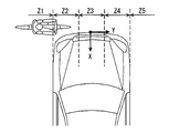
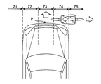
- the primary collision position specifying unit 143 includes a vehicle front end portion and a region including the side thereof as shown in FIG. 3 such as a left side portion Z1, a left front end portion Z2, a center portion Z3, and a right front end portion. It is assumed that five zones of Z4 and right side portion Z5 are defined, and which zone the primary collision position belongs to is determined.
- the left side portion Z1 indicates an area further left than the left corner of the front end portion of the vehicle, and the left front end portion Z2 is a fixed distance (for example, 0.4 m from the left corner toward the center of the front end portion). ).
- the right side portion Z5 refers to an area on the right side of the right corner of the front end portion of the vehicle, and the right front end portion Z4 is a constant distance (for example, 0.4 m) from the right corner toward the center of the front end portion. And the area up to.
- the central portion Z3 is an area sandwiched between the left front end portion Z2 and the right front end portion Z4.
- the case where the primary collision position is the left side part Z1 means that the front wheel part of the bicycle and the vehicle This means that the front end (for example, the left front end Z2) is colliding.
- the case where the primary collision position is the right side portion Z5 means the case where the rear wheel portion of the bicycle and the vehicle front end portion (for example, the right front end portion Z4) collide.
- the primary collision position may be represented by coordinates in an XY coordinate system.
- the collision object specifying unit 141 determines that the collision object is a bicycle with an occupant
- the relative speed acquired by the relative speed acquisition unit 142 and the primary collision position specified by the primary collision position specifying unit 143 are two.
- the next collision position estimation unit 15 is provided.
- the secondary collision position estimation unit 15 is based on the relative speed and primary collision position of the occupant bicycle as the collision object provided from the collision object information acquisition unit 14 and the estimation data stored in the data storage unit 1M.
- a position (referred to as a secondary collision position) at which a predetermined protection target site such as the head or chest of an occupant of a bicycle with an occupant colliding with the own vehicle collides with the body of the own vehicle (referred to as a secondary collision position) is estimated .
- the secondary collision position estimation unit 15 is based on the relative speed of the bicycle with the occupant as the collision object, the primary collision position, and the estimation data.
- the position where the head collides secondarily on the outer surface of the vehicle body and the position where the chest collides secondarily on the outer surface of the vehicle body are estimated.
- the secondary collision position estimated by the secondary collision position estimation unit 15 is provided to the motion device selection unit 16.
- the estimation data is data indicating a correspondence relationship between a relative speed of a bicycle with a passenger as a collision object, a primary collision position, and a secondary collision position of each protection target part.
- the operation device selection unit 16 is a device to operate the external protection device 5 corresponding to the secondary collision position estimated by the secondary collision position estimation unit 15 among the plurality of external protection devices 5 mounted on the host vehicle. Select as (operating device). For example, when the secondary collision position of the head is the windshield and the secondary collision position of the chest is the hood portion, the pop-up hood 5A and the WS airbag 5D are selected as the operation devices.
- the external protection device 5 corresponding to the secondary collision position estimated by the secondary collision position estimation unit 15 corresponds to the external protection device 5 corresponding to an area where a passenger of the two-wheeled mobile body may collide with the secondary. . That is, the external protection device 5 corresponding to the secondary collision position is the external protection device 5 that can protect the occupant of the two-wheeled mobile body that has collided with the host vehicle from the secondary collision. In other words, the operation device selection unit 16 does not select an external protection device that does not contribute to the protection of the occupant of the two-wheeled mobile body that collides with the host vehicle (that is, cannot be protected).
- the operation instruction unit 17 outputs an operation instruction signal for instructing the external protection device 5 selected by the operation device selection unit 16 to operate and operates it. According to such an aspect, the external protection device 5 that can protect the occupant of the two-wheeled mobile body that has primarily collided with the host vehicle is operated.
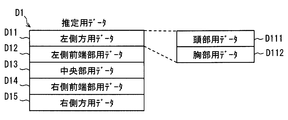
- the estimation data D1 is data for the secondary collision position estimation unit 15 to estimate the secondary collision position of the protection target part based on the relative speed of the occupant bicycle as the collision object and the primary collision position. is there.
- the estimation data may be data including data D11 to D15 corresponding to the primary collision positions Z1 to Z5 in a list format as shown in FIG. 4, for example.
- Each of the data D11 to D15 corresponding to the primary collision positions Z1 to Z5 further includes data for each protection target part, and the data for each protection target part is the secondary of the protection target part at the primary collision position.
- the data shows the correspondence between the collision position and the relative speed.
- the data D11 is data (hereinafter referred to as data for the left side) indicating the correspondence between the secondary collision position and the relative speed for each protection target site when the primary collision position is the left side portion Z1.
- the left side data D11 includes the head data D111 indicating the correspondence between the secondary collision position of the head and the relative velocity when the primary collision position is the left side Z1, and the secondary collision of the chest.
- Chest data D112 indicating the correspondence between the position and the relative speed is provided.
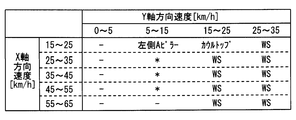
- FIG. 5 is a diagram showing a configuration of the head data D111 included in the left side data D11. With reference to FIG. 5, a schematic configuration of data indicating the correspondence between the secondary collision position and the relative speed for each protection target site will be described.
- the head data D111 is data indicating the secondary collision position of the head according to the Y-axis direction speed Vy and the X-axis direction speed Vx of the bicycle with the occupant with respect to the host vehicle.
- the head data D111 divides the possible range of the X-axis direction speed and the Y-axis direction speed into a plurality of speed sections having a predetermined width, and the Y-axis direction speeds Vy and X
- the correspondence relationship between the axial velocity Vx and the secondary collision position is data represented in a table format.
- the secondary collision position estimation unit 15 is based on a combination of speed sections to which the X-axis direction speed Vx and the Y-axis direction speed Vy acquired by the relative speed acquisition unit 142 belong. Then, the secondary collision position of the head is estimated. For example, when the primary collision position is the left side Z1, the Y-axis direction speed Vy is 10 km / h, and the X-axis direction speed Vx is 20 km / h, the secondary collision position of the head is A on the left side of the vehicle. Presumed to be a pillar.
- WS indicates a windshield
- ⁇ indicates a road surface (that is, no secondary collision)
- * indicates a portion of the body of the host vehicle that the external protection device 5 does not support. Represents. According to such data, it is possible to determine not only the secondary collision position but also whether or not a secondary collision occurs.
- the left side data D11 and the head data D111 included in the left side data D11 are described here, but the data corresponding to the other primary collision positions has the same configuration.
- the estimation data D1 described above may be generated by performing a simulation or an actual vehicle test.
- the secondary collision position is not uniquely determined only by the relative speed and the primary collision position, but the shape of the vehicle on which the protection device control system 100 is mounted, the size of a bicycle with a passenger as a collision object, the collision It can also change depending on the direction of travel of the bicycle and the height of the center of gravity of the passenger. Therefore, the estimation data D1 may be data considering the various elements described above.
- the mode of estimating the secondary collision position of the protection target part such as the head and the chest based on the estimation data designed in advance is illustrated. Not limited to this.
- the inventors have obtained the following knowledge (details will be described later) on the behavior of a bicycle occupant after a primary collision with the host vehicle.
- the secondary collision position estimation unit 15 may calculate the secondary collision position based on a behavior pattern that models the behavior of the occupant after the primary collision based on the knowledge.
- the behavior pattern may be represented by a function having parameters such as a primary collision position and a relative speed.
- the portion of the occupant's body above the waist ie, the upper body
- the portion of the occupant's body above the waist ie, the upper body
- the lower half of the leg or the like has a posture along the shape of the vehicle.
- a force that pushes the bicycle forward is applied to the bicycle by the front end portion of the vehicle, while the upper portion of the bicycle is pulled to the vehicle side by being in contact with the occupant's body, so the bicycle also falls to the vehicle side.
- posture a force that pushes the bicycle forward
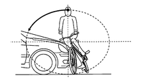
- the vehicle body collides with the occupant's waist
- the occupant begins to rotate so that the upper body including the head falls over the vehicle.
- the locus of the occupant's head at that time can be approximated to an ellipse centered on the position where the waist and the vehicle body are in contact.
- the contact position between the waist as the center of the elliptical track and the vehicle body is determined according to the vehicle shape such as the height of the front end of the vehicle and the height of the waist of the occupant.
- the lengths of the major and minor axes of the elliptical trajectory are determined according to the relative speed and the length from the occupant's waist to the head.
- the secondary collision position estimation unit 15 determines an elliptical trajectory as a head trajectory and an area where the vehicle body is formed, which is determined based on the vehicle shape, the occupant's posture, the relative speed, the collision position, and the like. By collating, the secondary collision position of the head can be estimated. In other words, the secondary collision position estimation unit 15 can estimate the secondary collision position of the head without using the table shown in FIG. 5 by defining the function corresponding to the behavior of the occupant described above. .
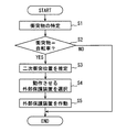
- protection device control processing processing for protecting the bicycle occupant from the secondary collision (referred to as protection device control processing) performed by the control device 1 will be described using the flowchart shown in FIG. 9.
- the flowchart shown in FIG. 9 may be started when the collision detection unit 11 detects a primary collision, for example.
- the described flowchart includes a plurality of sections (or referred to as steps), and each section is expressed as, for example, S1. Further, each section can be divided into a plurality of subsections, while a plurality of sections can be combined into one section.
- Each section may be referred to as a device, or as a unique name, and with structural modifiers, for example, a primary collision detection section may be referred to as a primary collision detection device, a primary collision detector (detector). it can.
- the section includes (i) not only a section of software combined with a hardware unit (eg, a computer) but also (ii) a section of hardware (eg, an integrated circuit, a wiring logic circuit) and related devices. It can be realized with or without the function.
- the hardware section can be included inside the microcomputer.
- the collision object identification unit 141 identifies the collision object. If the colliding object is a bicycle with an occupant as a result of the specifying process in S1, S2 becomes YES and the process proceeds to S3. On the other hand, when the collision object is not a bicycle with a passenger, S2 is NO and this flow is finished.
- the relative speed acquisition unit 142 uses the X-axis direction speed Vx and the Y-axis direction of the occupant bicycle as the collision object. While acquiring the speed Vy, the primary collision position specific
- the secondary collision position estimation unit 15 determines the head and chest of the occupant of the bicycle that collided with the own vehicle based on the relative speed, the primary collision position, and the estimation data of the bicycle with the occupant that collided with the own vehicle.
- the secondary collision position is estimated and the process proceeds to S4.
- the operation device selection unit 16 selects an operation device from among the various external protection devices 5 based on the secondary collision position estimated by the secondary collision position estimation unit 15. Specifically, the external protection device 5 corresponding to the secondary collision position estimated by the secondary collision position estimation unit 15 is selected as the external protection device 5 to be operated.
- any external protection device 5 included in the host vehicle does not correspond to the secondary collision position or when it is estimated that a secondary collision with the host vehicle does not occur, any external protection device 5 is provided. Is not selected as the operating device.
- the process in S4 proceeds to S5.
- the operation instruction unit 17 outputs an operation instruction signal to the external protection device 5 selected by the operation device selection unit 16 to operate, and this flow is finished.
- the secondary collision position estimation unit 15 estimates the secondary collision position of the bicycle occupant who collided with the host vehicle, and the motion device selection unit 16 performs the external collision corresponding to the portion where the occupant performs the secondary collision.
- the protection device 5 is selected.
- the operation instruction unit 17 operates the selected external protection device 5. That is, the external protective device 5 corresponding to the secondary collision position of the bicycle occupant who collided with the host vehicle is operated.
- the external protection device 5 that does not cause a secondary collision is not operated. That is, according to the above configuration, when the host vehicle and the bicycle with the occupant have a primary collision, it is possible to suppress the operation of the protective device unnecessary for protecting the bicycle occupant.
- the bicycle and the occupant are separated objects, and
- the movement of the bicycle occupant with respect to the host vehicle after the primary collision is the behavior of the pedestrian because the movement speed is higher than the pedestrian and the center of gravity of the bicycle occupant is higher than the pedestrian. And different.
- the passenger of the bicycle does not make a secondary collision with the host vehicle and moves toward the traveling direction of the bicycle according to the law of inertia.
- the vehicle may flow to the road surface on the side of the existing vehicle.
- the inventors have a region in which the primary collision position with the bicycle is closer to the traveling direction side of the bicycle than the center P of the front end portion of the vehicle, as shown in FIG.
- the speed in the Y-axis direction of the bicycle with the occupant is 10 km / h or more
- the occupant of the bicycle that primarily collided with the own vehicle does not collide with the own vehicle and the road surface in the traveling direction side of the bicycle.
- the knowledge that there is a tendency to collide was acquired.
- the region closer to the bicycle traveling direction than the center P at the front end of the vehicle is a region on the right side of the center P when the bicycle is traveling to the vehicle width direction right side for the vehicle.
- bicycles unlike pedestrians, bicycles have body parts such as front and rear wheels in the direction of travel. Therefore, just because the own vehicle collides with the bicycle with the passenger, the bicycle passenger does not always exist in front of the vehicle. In particular, when only the front wheels or only the rear wheels of the bicycle come into contact with the front end of the vehicle, the bicycle occupant tends to be flipped to the side of the vehicle. Even in such a case, a secondary collision between the bicycle occupant and the host vehicle does not occur.
- the behavior of humans to be protected varies greatly. If the collision object is a bicycle with a passenger, the passenger of the bicycle There are relatively many cases where the secondary collision does not occur compared to the case where the collision object is a pedestrian. In other words, when the collision object is a bicycle with an occupant, even when a primary collision occurs, the case where the external protection device 5 does not need to be operated is relatively compared to the case where the collision object is a pedestrian. Many.
- the secondary collision position estimation unit 15 is a region where the primary collision position of the occupant bicycle is closer to the traveling direction side of the bicycle than the center P of the front end of the vehicle, and When the Y-axis direction speed is 10 km / h or more, it may be estimated that there is no secondary collision. In that case, the operation device selection unit 16 considers that there is no external protection device 5 to be operated.
- the primary collision position is a region closer to the bicycle traveling direction than the center P in the vehicle width direction of the front end portion of the vehicle, and the speed in the Y-axis direction is 10 km / h or more.
- the head and the chest are adopted as the protection target parts, and the secondary collision position estimation unit 15 exemplifies a mode in which each secondary collision position is estimated.
- the body part estimated by the secondary collision position estimating unit 15 may be only the head or only the chest. Further, the portion to be protected is not limited to the head or chest. An arm part, a waist part, etc. are good also as a protection object part. That is, the secondary collision position estimation unit 15 may estimate a secondary collision position such as an arm or a waist, and the motion device selection unit 16 may select a motion device based on the estimation result.
- the primary collision position is the left front end Z2 and the secondary collision position of the head is a cowl top
- the WS airbag 5D but also the pop-up hood 5A should be operated.
- Select as 5 This is because, when the head collides with the cowl top, there is a high possibility that the chest collides with the hood portion located on the primary collision position side of the cowl top.
- the external protection device 5 corresponding to the portion where the chest may possibly collide is operated. Can be made.
- the motion device selection unit 16 In addition to the external protection device 5 corresponding to the secondary collision position, the external protection device 5 having a region within a certain range from the half line from the primary collision position to the secondary collision position of the chest as a corresponding region is also operated. The external protective device 5 may be selected.
- the primary collision position is the left front end Z2 and the secondary collision position of the chest is the hood portion
- the pop-up hood 5A but also the WS airbag 5D should be operated.
- Select as 5 This is because when the chest collides with the hood part, the bicycle occupant's head is more likely to collide with the cowl top or windshield existing behind the hood than the hood.
- the external protection device 5 corresponding to a portion where the head may collide with the secondary collision. can be operated.
- the colliding object information acquisition unit 14 detects the head of the occupant of the bicycle when the colliding object identification unit 141 determines that the collision object is a bicycle with an occupant.
- a head position acquisition unit 144 (or a head position acquisition unit 144) that acquires an initial head position that is a relative position of the part to the host vehicle.
- the initial head position may be specified by the image recognition unit 13 performing a known pattern matching process on the image captured by the camera 3.
- the secondary collision position estimation unit 15 determines whether the head of the bicycle occupant is based on the initial head position acquired by the head position acquisition unit 144 and the relative speed acquired by the relative speed acquisition unit.
- a head collision position that is a position where the vehicle collides with the host vehicle is estimated.
- the head collision position may be estimated using data indicating the correspondence relationship between the initial head position and the relative velocity generated based on various tests.
- you may estimate based on the head behavior pattern which modeled the behavior of the passenger
- the head behavior pattern may be expressed by a function having parameters such as the initial head position and relative speed.
- the operation device selection unit 16 selects the external protection device 5 corresponding to the head collision position estimated by the secondary collision position estimation unit 15 as the external protection device 5 to be operated. Also according to such an aspect, a bicycle occupant who has collided with the host vehicle can be protected. The same processing may be applied to the chest of a bicycle occupant.
- the collision object specifying unit 141 detects the object existing in the position closest to the host vehicle at the time (or immediately before) when the collision detection unit 11 detects the primary collision among the detection objects existing in the forward detection area. Although it was set as the aspect which determines with a thing being a collision object, it is not restricted to this.
- the collision object information acquisition unit 14 determines the collision margin that is the time remaining until the collision as an index indicating the risk of collision for each detected object existing in the detection area from the relative position and relative speed of the detected object. You may calculate time (TTC: Time to Collision).
- the colliding object identification unit 141 may collide with the host vehicle a detected object whose TTC is equal to or less than a predetermined threshold (for example, 3 seconds) and the smallest value. Recognize as an object (a collision object candidate). And when the collision detection part 11 detects a primary collision in the state which has recognized the collision object candidate, you may determine the collision object candidate as a collision object.
- a predetermined threshold for example, 3 seconds
- the relative speed acquisition unit 142 sequentially estimates the relative speed of the collision object candidate, and when the collision detection unit 11 detects a primary collision, the relative speed estimated immediately before is detected as the primary speed. What is necessary is just to employ
- the primary collision position specifying unit 143 sequentially estimates the position where the primary collision occurs from the relative position and relative speed of the colliding object candidate, and the position estimated immediately before the collision detecting unit 11 detects the primary collision. May be determined as the primary collision position.
- estimation data (or behavior pattern) indicating a correspondence relationship between a relative speed and a primary collision position when a motorcycle and a vehicle on which the occupant rides have a primary collision. ) May be generated by various tests.
- the person to be protected by the protection device control system 100 is not limited to a two-wheeled vehicle occupant. If the collision object is a pedestrian, a process for protecting the pedestrian from a secondary collision may be performed. A passenger of a tricycle (so-called trike) may be protected.
Landscapes
- Engineering & Computer Science (AREA)
- Mechanical Engineering (AREA)
- Radar, Positioning & Navigation (AREA)
- Remote Sensing (AREA)
- Traffic Control Systems (AREA)
Priority Applications (2)
| Application Number | Priority Date | Filing Date | Title |
|---|---|---|---|
| DE112016003108.4T DE112016003108B4 (de) | 2015-07-09 | 2016-06-24 | Schutzsteuervorrichtung |
| US15/742,395 US10351087B2 (en) | 2015-07-09 | 2016-06-24 | Protection control apparatus |
Applications Claiming Priority (2)
| Application Number | Priority Date | Filing Date | Title |
|---|---|---|---|
| JP2015138054A JP2017019378A (ja) | 2015-07-09 | 2015-07-09 | 保護制御装置 |
| JP2015-138054 | 2015-07-09 |
Related Child Applications (1)
| Application Number | Title | Priority Date | Filing Date |
|---|---|---|---|
| US15/742,395 Continuation US10351087B2 (en) | 2015-07-09 | 2016-06-24 | Protection control apparatus |
Publications (1)
| Publication Number | Publication Date |
|---|---|
| WO2017006532A1 true WO2017006532A1 (ja) | 2017-01-12 |
Family
ID=57685371
Family Applications (1)
| Application Number | Title | Priority Date | Filing Date |
|---|---|---|---|
| PCT/JP2016/003045 Ceased WO2017006532A1 (ja) | 2015-07-09 | 2016-06-24 | 保護制御装置 |
Country Status (4)
| Country | Link |
|---|---|
| US (1) | US10351087B2 (enExample) |
| JP (1) | JP2017019378A (enExample) |
| DE (1) | DE112016003108B4 (enExample) |
| WO (1) | WO2017006532A1 (enExample) |
Cited By (1)
| Publication number | Priority date | Publication date | Assignee | Title |
|---|---|---|---|---|
| JP2022150232A (ja) * | 2021-03-26 | 2022-10-07 | 本田技研工業株式会社 | 制御装置、制御方法、およびプログラム |
Families Citing this family (9)
| Publication number | Priority date | Publication date | Assignee | Title |
|---|---|---|---|---|
| JP6485417B2 (ja) * | 2016-08-05 | 2019-03-20 | トヨタ自動車株式会社 | 車両用衝突検出装置及び車両用衝突検出方法 |
| JP6806017B2 (ja) | 2017-09-25 | 2020-12-23 | 株式会社デンソー | 保護制御装置 |
| JP6806018B2 (ja) | 2017-09-25 | 2020-12-23 | 株式会社デンソー | 保護制御装置及び保護システム |
| JP2021014131A (ja) * | 2017-10-31 | 2021-02-12 | パナソニックIpマネジメント株式会社 | 感圧装置、及び車両 |
| JP2019166922A (ja) * | 2018-03-22 | 2019-10-03 | いすゞ自動車株式会社 | 車両の自転車乗員保護装置 |
| JP2020023235A (ja) * | 2018-08-07 | 2020-02-13 | 本田技研工業株式会社 | 車両用保護装置および車両 |
| KR102756881B1 (ko) * | 2019-07-23 | 2025-01-21 | 엘지전자 주식회사 | 차랑에 탑재되어 자가진단을 수행하는 인공 지능 장치 및 그 방법 |
| KR102771430B1 (ko) * | 2020-05-12 | 2025-02-24 | 현대모비스 주식회사 | 보행자 보호장치 및 그 제어방법 |
| US11718254B2 (en) * | 2020-11-03 | 2023-08-08 | Rod Partow-Navid | Impact prevention and warning system |
Citations (1)
| Publication number | Priority date | Publication date | Assignee | Title |
|---|---|---|---|---|
| JP2003226211A (ja) * | 2002-02-04 | 2003-08-12 | Nissan Motor Co Ltd | 車両用保護装置 |
Family Cites Families (8)
| Publication number | Priority date | Publication date | Assignee | Title |
|---|---|---|---|---|
| JP2004017812A (ja) | 2002-06-17 | 2004-01-22 | Mazda Motor Corp | 車両用衝突保護装置 |
| JP3925653B2 (ja) | 2003-07-24 | 2007-06-06 | トヨタ自動車株式会社 | 車両の衝突保護装置 |
| DE102004006196A1 (de) | 2004-02-09 | 2005-08-25 | Robert Bosch Gmbh | Schutzsystem für Verkehrsteilnehmer |
| JP4760715B2 (ja) * | 2004-12-28 | 2011-08-31 | 株式会社豊田中央研究所 | 車両運動制御装置 |
| JP5447108B2 (ja) | 2010-04-05 | 2014-03-19 | 株式会社豊田中央研究所 | 保護制御装置 |
| JP2012131463A (ja) * | 2010-12-24 | 2012-07-12 | Honda Motor Co Ltd | 車両の歩行者衝突位置判定装置 |
| JP5700263B2 (ja) * | 2013-01-22 | 2015-04-15 | 株式会社デンソー | 衝突傷害予測システム |
| DE102013212477A1 (de) | 2013-06-27 | 2014-12-31 | Robert Bosch Gmbh | Verfahren und Vorrichtung zum Betreiben eines Kraftfahrzeugs, Computer-Programmprodukt |
-
2015
- 2015-07-09 JP JP2015138054A patent/JP2017019378A/ja active Pending
-
2016
- 2016-06-24 WO PCT/JP2016/003045 patent/WO2017006532A1/ja not_active Ceased
- 2016-06-24 DE DE112016003108.4T patent/DE112016003108B4/de active Active
- 2016-06-24 US US15/742,395 patent/US10351087B2/en active Active
Patent Citations (1)
| Publication number | Priority date | Publication date | Assignee | Title |
|---|---|---|---|---|
| JP2003226211A (ja) * | 2002-02-04 | 2003-08-12 | Nissan Motor Co Ltd | 車両用保護装置 |
Cited By (3)
| Publication number | Priority date | Publication date | Assignee | Title |
|---|---|---|---|---|
| JP2022150232A (ja) * | 2021-03-26 | 2022-10-07 | 本田技研工業株式会社 | 制御装置、制御方法、およびプログラム |
| US12090941B2 (en) | 2021-03-26 | 2024-09-17 | Honda Motor Co., Ltd. | Control device, control method, and storage medium |
| JP7561670B2 (ja) | 2021-03-26 | 2024-10-04 | 本田技研工業株式会社 | 制御装置、制御方法、およびプログラム |
Also Published As
| Publication number | Publication date |
|---|---|
| US20180194315A1 (en) | 2018-07-12 |
| DE112016003108B4 (de) | 2022-04-28 |
| JP2017019378A (ja) | 2017-01-26 |
| DE112016003108T5 (de) | 2018-04-12 |
| US10351087B2 (en) | 2019-07-16 |
Similar Documents
| Publication | Publication Date | Title |
|---|---|---|
| WO2017006532A1 (ja) | 保護制御装置 | |
| JP6337834B2 (ja) | 保護制御装置 | |
| JP4760715B2 (ja) | 車両運動制御装置 | |
| JP6555072B2 (ja) | 保護制御装置 | |
| CN104276121B (zh) | 控制车辆安全参数的系统、车辆和控制安全参数的方法 | |
| US7447592B2 (en) | Path estimation and confidence level determination system for a vehicle | |
| JP6512164B2 (ja) | 物体検出装置、物体検出方法 | |
| JP7747733B2 (ja) | 車両の道路両立性を改善するための安全システム、車両安全システムおよび装置、方法、ならびに媒体 | |
| US11180081B2 (en) | Rear-side alarm device and rear-side alarm method thereof | |
| JP2008247111A (ja) | 車両の衝突安全制御システム | |
| JP2019046143A (ja) | 走行支援装置 | |
| JP6794972B2 (ja) | 保護制御装置 | |
| CN111284373B (zh) | 一种座椅控制方法、装置、车辆和计算机可读存储介质 | |
| JP6409736B2 (ja) | ポップアップ制御装置 | |
| US11603073B2 (en) | Outside protection apparatus for vehicle | |
| CN114364578B (zh) | 用于适配个人约束装置的触发算法的方法和用于适配个人约束装置的触发算法的控制装置 | |
| JP2007308110A (ja) | 歩行者保護装置 | |
| CN118457568A (zh) | 用于避免碰撞或减小冲击力的方法和装置 | |
| KR102591195B1 (ko) | 차량 및 그 제어방법 | |
| JP6806018B2 (ja) | 保護制御装置及び保護システム | |
| KR101596995B1 (ko) | 차량의 충격완화 방법 | |
| CN221541487U (zh) | 车辆防护气囊系统 | |
| US20230406250A1 (en) | Vehicle for protecting occupant and operating method thereof | |
| WO2019001887A1 (en) | A vehicle safety system | |
| KR20150097940A (ko) | 차량의 에어백 전개 알고리즘 장치 및 전개 알고리즘 방법 |
Legal Events
| Date | Code | Title | Description |
|---|---|---|---|
| 121 | Ep: the epo has been informed by wipo that ep was designated in this application |
Ref document number: 16821011 Country of ref document: EP Kind code of ref document: A1 |
|
| WWE | Wipo information: entry into national phase |
Ref document number: 112016003108 Country of ref document: DE |
|
| 122 | Ep: pct application non-entry in european phase |
Ref document number: 16821011 Country of ref document: EP Kind code of ref document: A1 |