WO2017002406A1 - 車両ドア用インサイドハンドル - Google Patents
車両ドア用インサイドハンドル Download PDFInfo
- Publication number
- WO2017002406A1 WO2017002406A1 PCT/JP2016/057990 JP2016057990W WO2017002406A1 WO 2017002406 A1 WO2017002406 A1 WO 2017002406A1 JP 2016057990 W JP2016057990 W JP 2016057990W WO 2017002406 A1 WO2017002406 A1 WO 2017002406A1
- Authority
- WO
- WIPO (PCT)
- Prior art keywords
- vehicle
- recess
- inside handle
- vehicle door
- handle
- Prior art date
- Legal status (The legal status is an assumption and is not a legal conclusion. Google has not performed a legal analysis and makes no representation as to the accuracy of the status listed.)
- Ceased
Links
Images



Classifications
-
- E—FIXED CONSTRUCTIONS
- E05—LOCKS; KEYS; WINDOW OR DOOR FITTINGS; SAFES
- E05B—LOCKS; ACCESSORIES THEREFOR; HANDCUFFS
- E05B85/00—Details of vehicle locks not provided for in groups E05B77/00 - E05B83/00
- E05B85/10—Handles
- E05B85/12—Inner door handles
-
- B—PERFORMING OPERATIONS; TRANSPORTING
- B60—VEHICLES IN GENERAL
- B60J—WINDOWS, WINDSCREENS, NON-FIXED ROOFS, DOORS, OR SIMILAR DEVICES FOR VEHICLES; REMOVABLE EXTERNAL PROTECTIVE COVERINGS SPECIALLY ADAPTED FOR VEHICLES
- B60J5/00—Doors
- B60J5/04—Doors arranged at the vehicle sides
-
- E—FIXED CONSTRUCTIONS
- E05—LOCKS; KEYS; WINDOW OR DOOR FITTINGS; SAFES
- E05B—LOCKS; ACCESSORIES THEREFOR; HANDCUFFS
- E05B79/00—Mounting or connecting vehicle locks or parts thereof
- E05B79/02—Mounting of vehicle locks or parts thereof
- E05B79/06—Mounting of handles, e.g. to the wing or to the lock
-
- E—FIXED CONSTRUCTIONS
- E05—LOCKS; KEYS; WINDOW OR DOOR FITTINGS; SAFES
- E05Y—INDEXING SCHEME ASSOCIATED WITH SUBCLASSES E05D AND E05F, RELATING TO CONSTRUCTION ELEMENTS, ELECTRIC CONTROL, POWER SUPPLY, POWER SIGNAL OR TRANSMISSION, USER INTERFACES, MOUNTING OR COUPLING, DETAILS, ACCESSORIES, AUXILIARY OPERATIONS NOT OTHERWISE PROVIDED FOR, APPLICATION THEREOF
- E05Y2900/00—Application of doors, windows, wings or fittings thereof
- E05Y2900/50—Application of doors, windows, wings or fittings thereof for vehicles
- E05Y2900/53—Type of wing
- E05Y2900/531—Doors
Definitions
- the present invention relates to an inside handle for a vehicle door.
- FIG. 8 shows an inside handle 100 that is rotatably supported on the inner surface of the vehicle door.
- the inside handle 100 includes a rotation center 101 whose axis is directed in the vertical direction when mounted on the vehicle door. That is, the inside handle 100 is supported by the vehicle door so as to be rotatable around its rotation center 101.
- the locking device built in the vehicle door is in an unlatched state (a state in which the vehicle door can be opened with respect to the vehicle body).
- the inside handle 100 has a structure in which the surface of a resin handle body is covered with metal plating.
- the inside handle 100 is attached to the vehicle interior design surface 102 that constitutes the vehicle interior side when attached to the vehicle door, the vehicle exterior design surface 103 that constitutes the vehicle exterior side when attached to the vehicle door, and the vehicle door. And a bottom surface constituting surface 104 that constitutes the bottom surface.
- a concave portion 105 having a substantially triangular shape is formed on the bottom surface constituting surface 104 of the inside handle 100.
- the inner surface of the recess 105 on the vehicle interior design surface 102 side has a shape extending along the side edge of the bottom surface constituting surface 104 on the vehicle interior design surface 102 side.
- the inner surface on the vehicle exterior design surface 103 side of the recess 105 has a shape extending along the side edge portion on the vehicle exterior design surface 103 side of the bottom surface constituting surface 104.
- the parts located on both sides of the concave portion 105 of the inside handle 100 constitute thin portions 106 and 107 extending in the longitudinal direction of the inside handle 100.
- the inner surface of the recessed portion 105 on the vehicle interior design surface 102 side and the inner surface of the vehicle exterior design surface 103 side are connected to each other at the ends located on the distal end side of the inside handle 100. That is, the inside handle 100 has a connection portion 108 that connects one ends of the thin portions 106 and 107.
- the recess 105 is formed when the handle main body is formed using a resin material. And this recessed part 105 contributes to the weight reduction of the inside handle 100, and generation
- the resin handle body causes thermal expansion at high temperatures. Therefore, when the inside handle 100 is heated after manufacturing and the two thin portions 106 and 107 are thermally expanded, the thin portions 106 and 107 are connected to each other around the connection portion 108 as shown by arrows in FIG. It may be distorted (deformed) in the separating direction.
- the inside handle 100 may generate a large distortion at the connection portion 108. Then, a stress caused by the large strain is generated in the connection portion 108, and when this stress exceeds the allowable stress of plating, the plating may be largely cracked in the connection portion 108. And when it cracks greatly, there exists a possibility that this crack may extend to the vehicle interior design surface 102 and the vehicle exterior design surface 103 which are easy to enter into a passenger's field of view.
- the plating is formed thicker. In this way, even if a large stress is generated in the connection portion 108 due to the high temperature of the inside handle 100, the possibility that the plating will crack greatly in the connection portion 108 due to this stress is reduced. As a result, the risk of cracks occurring at the connection site 108 reaching the vehicle interior design surface 102 and the vehicle exterior design surface 103 is reduced. However, if the plating is formed thicker, the manufacturing cost of the inside handle 100 is increased.
- An object of the present invention is to provide an inside handle for a vehicle door that can effectively prevent cracks in the plating on the outside design surface and the inside design surface due to the high temperature of the inside handle without increasing the plating.
- the present invention includes a resin-made handle body rotatably supported on the inner surface of the vehicle door for operating a locking device provided on the vehicle door, and a plating covering the surface of the handle body.
- a vehicle interior design surface and the vehicle exterior design surface that respectively constitute an interior side surface and an exterior side surface of the handle body when mounted on the vehicle door, and an upper surface of the handle body when mounted on the vehicle door.
- a reinforcing rib is provided in the recess of the inside handle of the present invention.
- the reinforcing rib extends in a direction connecting the vehicle interior design surface and the vehicle exterior design surface of the inside handle. Furthermore, both ends of the reinforcing rib are connected to the inner surface of the recess. Therefore, even if the two parts located between the interior design surface and the exterior design surface and the recess are caused to thermally expand because the inside handle is heated after manufacturing, the two parts are mutually connected. It can prevent large distortion in the direction of leaving. Therefore, it can prevent that the connection site
- the recess constitutes the interior design surface side portion of the interior surface of the recess, the interior surface of the interior of the vehicle interior extending along the side edge of the interior design surface side of the recess formation surface, and the interior surface of the recess A vehicle exterior design surface side portion, and a vehicle exterior interior surface extending along a lateral edge of the recess formation surface on the vehicle exterior design surface side, and the vehicle interior surface and the tip of the vehicle interior surface
- the distance between the inner surface on the inner side and the inner surface on the outer side of the vehicle may gradually become narrower as the end portions on the portion side cross each other and go from the center of rotation toward the tip side.
- the end surface of the reinforcing rib on the concave portion forming surface side may be positioned closer to the bottom of the concave portion than the concave portion forming surface.
- the connecting portion between the reinforcing rib and the inner surface of the recess is likely to have a greater stress than the peripheral portion. Therefore, the plating may cause (small) cracks in the connection portion (however, such a situation may occur when the reinforcing rib is not provided and the interior design surface and the exterior design surface are provided. From the possibility of cracking to the parts covering the car exterior design surface and the car interior design surface due to the distortion that occurs in the connection part adjacent to the two parts located between the recess and the recess Is low).
- the connecting portion between the reinforcing rib and the inner surface of the recess is located closer to the bottom of the recess than the recess forming surface. That is, the distance on the inside handle surface from the connection portion to the vehicle exterior design surface and the vehicle interior design surface is longer than that in the case where the connection portion is located at the same position as the non-recessed surface. Therefore, the possibility that the cracks reach the parts covering the plated exterior side design surface and the interior side design surface is lower than when the connecting portion is located at the same position as the non-recessed surface.
- the connecting portion (reinforcing rib) is located on the bottom side of the concave portion with respect to the concave forming surface, even if the plating cracks at the connecting portion, the crack can enter the passenger's field of view. The nature is not high.
- the concave portion has a polygonal shape having a plurality of corners, and is positioned closer to the bottom side of the concave portion than the concave portion forming surface at a portion constituting the angle of the peripheral portion of the concave portion forming surface side end portion of the concave portion A stepped portion may be formed.
- the “polygon” includes a substantially polygon.
- the corner portion When the inside handle is thermally expanded due to a high temperature after manufacture, the corner portion is likely to have a greater stress than the peripheral portion. However, the stress at the corner step portion is more likely to be greater than the portion where the corner step portion is not formed. Therefore, when plating causes cracks at the corners, there is a high possibility that (small) cracks will occur at the stepped portions.
- the step portion is located closer to the bottom of the recess than the recess formation surface. That is, the distance from the stepped portion to the vehicle exterior design surface and the vehicle interior design surface is longer than the distance on the inside handle surface from the recessed portion formation surface to the vehicle exterior design surface and vehicle interior design surface.
- the cracks in the plating generated in the step portion may reach the part covering the outer side design surface and the inner side design surface of the plating in the vicinity of the concave portion forming surface of the corner when there is no step portion. Lower than when the plating cracks.
- the stepped portion is located on the bottom side of the recessed portion with respect to the recessed portion forming surface. Therefore, even if the plating cracks at the step portion, the possibility that the crack will enter the passenger's field of view is not high.
- the step portion may be formed on the entire peripheral edge of the recess.
- the stepped portion is formed only at the corner portion, stress is increased at both ends of the stepped portion when the inside handle is thermally expanded, and as a result, the plating is likely to crack at both ends of the stepped portion.
- the step portion is formed on the entire peripheral edge of the recess, that is, when the recess has an annular shape, such a problem does not occur.
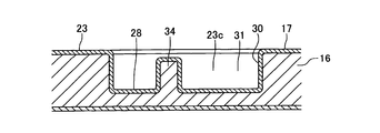
- FIG. 4 is a schematic cross-sectional view taken along the line IV-IV in FIG. 3. It is a bottom view of the inside handle of a 2nd embodiment of the present invention.
- FIG. 6 is a cross-sectional view taken along the line VI-VI in FIG. 5. It is sectional drawing corresponding to FIG. 6 of a comparative example. It is a bottom view of the conventional inside handle.
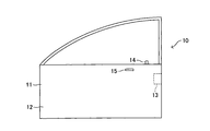
- a vehicle door 10 shown in FIG. 1 is supported so as to be rotatable about a vertical rotation axis with respect to a vehicle body (not shown), and an opening formed on a side surface of the vehicle body can be opened and closed.
- a vehicle interior side surface of the door main body portion 11 constituting the lower half portion of the vehicle door 10 is constituted by a resin trim 12.
- a lock device 13 is provided, a part of which is exposed at the rear end surface of the vehicle door 10.
- the lock device 13 has a known structure including a latch and a pole.
- the lock device 13 is linked to a lock knob 14 provided on the upper end surface of the trim 12 so as to be slidable in the vertical direction. Further, the lock device 13 is linked to an inside handle 15 rotatably supported by the trim 12 via an operation wire (not shown). Note that the lock knob 14 does not need to be provided on the upper end surface of the trim 12, and may be incorporated in the inside handle 15, for example.
- the lock knob 14 when the lock knob 14 is positioned in the lock position (not shown) when the vehicle door 10 closes the opening of the vehicle body, the striker (not shown) in which the latch of the lock device 13 is fixed to the vehicle body. It will be in the latch state which grasps. In this case, even if the inside handle 15 is rotated from the initial position (non-operation position), the latch maintains the latched state.
- the lock knob 14 is located at the unlock position (the position shown in FIG. 1), when the inside handle 15 is rotated from the initial position to the vehicle interior side, the latch of the lock device 13 enters an unlatched state in which the striker is released. Accordingly, the vehicle door 10 can be rotated in the opening direction with respect to the vehicle body.
- the inside handle 15 has a resin handle main body 16 constituting the entire shape thereof, and a plating 17 that is a metal thin film coated on the entire surface of the handle main body 16 (see FIG. 4). That is, the inside handle 15 is manufactured by forming the handle body 16 by resin molding and plating the surface of the handle body 16 after the shape of the handle body 16 is stabilized.
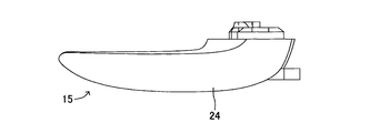
- the inside handle 15 has an overall shape shown in FIGS. That is, the inside handle 15 has an elongated shape.
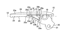
- a rotation center 19 that is a hole that linearly penetrates the inside handle 15 is formed in the vicinity of one end in the longitudinal direction of the inside handle 15.
- the axial direction of the rotation center 19 is a direction that becomes the vertical direction when the inside handle 15 is attached to the vehicle door 10.
- the inside handle 15 is attached to the trim 12 in a state in which a rotation center 19 is rotatably fitted to a rotation axis extending in a vertical direction of a base frame (not shown) fixed to the door panel.
- the positional relationship between the trim 12 and the inside handle 15 when the inside handle 15 attached to the trim 12 is in the initial position is as shown in FIG.
- the center of rotation of the inside handle 15 may be constituted by a shaft, and this shaft may be rotatably fitted to a hole formed in the base frame. Further, an arm portion 20 is projected from an end portion on the rotation center 19 side of the inside handle 15, and a wire connection hole 21 including a through hole is formed in the arm portion 20. The axial direction of the wire connection hole 21 is parallel to the rotation center 19.
- the wire connection hole 21 is a hole to which one end of the operation wire described above is connected.
- the surface constituting the lower surface is constituted by a recess forming surface 23.
- the surface constituting the inner side surface of the inside handle 15 is constituted by a vehicle interior design surface 24 formed of a curved surface.
- the surface constituting the vehicle outer side surface when mounted on the vehicle door 10 of the inside handle 15 is constituted by a vehicle outer side design surface 25 made of a curved surface except for the arm portion 20.
- the interior design surface 24 is a part that enters the field of view of the passenger of the vehicle when the inside handle 15 is mounted on the vehicle door 10 regardless of the rotational position of the inside handle 15 with respect to the vehicle door 10.
- the vehicle exterior design surface 25 is positioned on the vehicle exterior side from the vehicle interior side surface of the trim 12 and thus does not enter the passenger's field of view.
- a part of the outside design surface 25 moves to a position that enters the passenger's field of view.
- One recess 28 is formed in the recess forming surface 23 of the inside handle 15.
- the recess 28 is recessed from the recess forming surface 23 side toward the side opposite to the recess forming surface 23 of the inside handle 15 (the upper surface side of the inside handle 15 when the inside handle 15 is attached to the vehicle door 10).
- the part on the opposite side to the recess forming surface 23 (the upper end when mounted on the vehicle door 10) is closed.
- the recess 28 is provided between the tip of the inside handle 15 and the rotation center 19.
- the cross-sectional shape of the recess 28, that is, the shape cut by a plane orthogonal to the axis of the rotation center 19 is substantially a triangle.
- the inner peripheral surface of the recess 28 is constituted by three parts.
- the inner peripheral surface of the recess 28 is constituted by the rotation center side surface 30, the vehicle inner surface 31, and the vehicle outer surface 32.
- the portions where the rotation center side surface 30, the vehicle inner surface 31 and the vehicle outer surface 32 intersect each other constitute three corner portions 28a.
- the rotation center side surface 30 is a surface that constitutes a portion of the inner peripheral surface of the recess 28 that is located closest to the rotation center 19.
- the vehicle inner surface 31 is a surface that constitutes a portion of the inner peripheral surface of the recess 28 that is positioned on the vehicle interior design surface 24 side. As shown in the drawing, when the inside handle 15 is viewed from the concave portion forming surface 23 side, the vehicle inner surface 31 is substantially parallel to the side edge portion 23a of the concave portion forming surface 23 on the vehicle inner design surface 24 side. That is, when the inside handle 15 is viewed from the recess forming surface 23 side, the vehicle inner surface 31 extends along the side edge 23a.
- the vehicle inner surface 32 is a surface that constitutes a portion located on the vehicle outer design surface 25 side in the inner peripheral surface of the recess 28. As shown in the drawing, when the inside handle 15 is viewed from the concave portion forming surface 23 side, the vehicle inner surface 32 is substantially parallel to the side edge portion 23b of the concave portion forming surface 23 on the vehicle outer design surface 25 side. That is, when the inside handle 15 is viewed from the recess forming surface 23 side, the vehicle inner surface 32 extends along the side edge 23b.
- ends of the vehicle inner surface 31 and the vehicle outer surface 32 opposite to the rotation center 19 intersect each other. Further, the distance between the inner surface 31 on the inner side and the inner surface 32 on the outer side of the vehicle is gradually narrowed from the rotation center 19 side toward the distal end side of the inside handle 15. Further, in the inside handle 15, a portion located between the side edge 23a (the vehicle interior design surface 24) and the recess 28 (the vehicle interior surface 31) and the side edge 23b (the vehicle exterior design surface) and the recess 28 ( The parts located between the inner side 32) and the outer side of the vehicle constitute thin portions 23c, 23d extending in the longitudinal direction of the inside handle 15, respectively. Furthermore, the inside handle 15 has a connection portion 23e that connects one end of the thin portion 23c and the thin portion 23d (the end portion on the front end side of the inside handle 15).
- the inside handle 15 includes a reinforcing rib 34 provided in the recess 28.
- the reinforcing ribs 34 are members that extend in a direction connecting the vehicle inner surface 31 and the vehicle outer surface 32 when the inside handle 15 is viewed from the recess forming surface 23 side, and both end portions thereof are the vehicle inner surface 31 (thin wall portions). 23c) and the vehicle inner surface 32 (thin wall portion 23d). Further, the reinforcing rib 34 is not located at the central portion of the recess 28 but is located slightly closer to the distal end side of the inside handle 15 than the central portion. As shown in FIG. 4, the end surface of the reinforcing rib 34 on the recess forming surface 23 side is located on the bottom side of the recess 28 with respect to the recess forming surface 23.
- the handle body 16 of the inside handle 15 is made of resin. Therefore, when the inside handle 15 is heated after manufacturing, the handle body 16 is thermally expanded. That is, as in the prior art, when the inside handle 15 is heated, the thin portion 23c and the thin portion 23d tend to be distorted (will be deformed) in the direction away from each other around the connection portion 23e.
- the inside handle 15 includes a reinforcing rib 34 that connects portions located on the distal end side of the inside handle 15 with respect to the center portion of the vehicle inner surface 31 (thin wall portion 23c) and the vehicle outer surface 32 (thin wall portion 23d). Yes.
- the reinforcing rib 34 can prevent the thin portion 23c and the thin portion 23d from being greatly distorted in a direction away from each other. Accordingly, it is possible to prevent the connecting portion 23e of the inside handle 15 from being greatly distorted. Therefore, even if the plating 17 is not thickened, it is possible to suppress the plating 17 from generating a large stress at the connection portion 23e. Therefore, the plating 17 is greatly cracked at the connection portion 23e by this stress, and the crack extends to a portion covering the vehicle interior design surface 24 and the vehicle exterior design surface 25, that is, a region easily entering the passenger's field of view. Can be effectively prevented.
- the plating 17 generates a small stress at the connection portion 23e, and as a result, the plating 17 may cause a small crack at the connection portion 23e.
- the cracks are small, there is a low possibility that the cracks of the connection part 23e reach the vehicle interior design surface 24 and the vehicle exterior design surface 25.
- the connection part 23e is located on the lower surface side of the inside handle 15, even if the plating 17 cracks at the connection part 23e, there is almost no possibility that this crack will enter the passenger's field of view.
- the connecting portion between the inner side surface 31 (thin portion 23c) and the inner side surface 32 (thin portion 23d) and the reinforcing rib 34 is provided.
- the stress tends to be higher than that of the peripheral portion. Therefore, the plating 17 may cause (small) cracks in the connection portion (however, such a situation may occur because of the distortion generated in the connection portion 23e when the reinforcing rib 34 is not provided. This is lower than the possibility that the surface plating 17 will crack on the interior design surface 24 and the exterior design surface 25).
- connection portion between the inner surface 31 (thin wall portion 23 c) and the inner surface 32 (thin wall portion 23 d) and the reinforcing rib 34 is positioned above the recess forming surface 23.
- the distance on the surface of the inside handle 15 from the connecting portion to the vehicle interior design surface 24 and the vehicle exterior design surface 25 is longer than when the connection portion is at the same position as the recess forming surface 23.
- the possibility that the cracks reach the part of the plating 17 that covers the vehicle interior design surface 24 and the vehicle exterior design surface 25 is greater than that in the case where the connection portion is located at the same position as the recess formation surface 23. Lower.
- this connecting portion is located on the lower surface side of the inside handle 15 and is located above the recess forming surface 23. Therefore, even if the plating 17 cracks at the connection portion, there is almost no possibility that the crack will enter the passenger's field of view.
- a feature of the present embodiment is that a stepped portion 28b that is recessed one step upward from the recessed portion forming surface 23 is formed on the entire peripheral edge portion of the recessed portion 28 on the side of the recessed portion forming surface 23.
- the stepped portion 28b is located on the same plane as the end surface of the reinforcing rib 34 on the recess forming surface 23 side, and is continuous with the end surface of the reinforcing rib 34 on the recess forming surface 23 side.
- the three corners 28a of the recess 28 are likely to have higher stress than the peripheral part.
- the stepped portion 28b formed in the corner portion 28a is likely to have a higher stress than the portion of the corner portion 28a where the stepped portion 28b is not formed. Therefore, the plating 17 tends to cause (small) cracks at the step portions 28b formed at the three corner portions 28a.
- the step portion 28 b is located above the recess forming surface 23.
- the distance on the surface of the inside handle 15 from the stepped portion 28b to the vehicle interior design surface 24 and the vehicle exterior design surface 25 is larger than the distance from the recess forming surface 23 to the vehicle interior design surface 24 and the vehicle exterior design surface 25. long. Therefore, there is a possibility that the cracks of the plating 17 generated in the stepped portion 28b formed in the corner portion 28a may reach a portion of the plating 17 covering the interior design surface 24 and the exterior design surface 25 of the plating 17. When there is no part 28b, it is lower than when cracks occur in the vicinity of the recess forming surface of the corner part 28a.
- the plating 17 is cracked at a portion near the concave portion forming surface 23 of the corner portion 28 a, the crack is caused by the plating 17.
- the vehicle interior design surface 24 and the vehicle exterior design surface 25 may be sufficiently covered.
- the inside handle 15 is heated.
- the stress at both end portions of the stepped portion 28b tends to increase. That is, the plating 17 is likely to crack at both ends of the stepped portion 28b.
- the stepped portion 28b is formed on the entire peripheral edge of the end portion of the recessed portion 28 on the recessed portion forming surface 23 side as in the present embodiment, that is, when the recessed portion 28 has an annular shape. There is no fear.
- the stepped portion 28 b is located on the lower surface side of the inside handle 15 and is located above the recess forming surface 23. Therefore, even if the plating 17 cracks at the stepped portion 28b, there is almost no possibility that the crack will enter the passenger's field of view.
- the cross-sectional shape of the recess 28 may be an accurate triangle instead of a substantially triangle.
- the cross-sectional shape of the recess 28 may be a polygon (or a substantially polygon) other than a triangle (and a substantially triangle).
- the “polygon” in the claims is a concept including not only an accurate polygon but also a substantially polygon.
- the end face of the reinforcing rib 34 may be located at the same position as the recess forming face 23. Further, a concave portion 28 (concave forming surface 23) may be provided on the upper surface side (the side opposite to the concave portion forming surface 23) of the inside handle 15. The relative position of the reinforcing rib 34 in the recess 28 may be a position different from that in the above embodiment. In the second embodiment, the stepped portion 28 b may be provided only at a portion corresponding to each corner portion 28 a of the recessed portion 28.
Landscapes
- Engineering & Computer Science (AREA)
- Mechanical Engineering (AREA)
- Lock And Its Accessories (AREA)
Abstract
メッキを厚くすることなく、インサイドハンドルの高温化に起因する車外側意匠面や車内側意匠面におけるメッキのヒビ割れを効果的に防止できる車両ドア用インサイドハンドルを提供する。樹脂製のハンドル本体と、ハンドル本体の表面を被覆するメッキと、を備え、さらに、車内側意匠面及び車外側意匠面と、インサイドハンドルの上面と下面の一方をなす凹部形成面に形成された、ハンドル本体の回転中心とインサイドハンドルの先端部との間に位置する凹部と、凹部内に設けられた、車内側意匠面と車外側意匠面とを結ぶ方向に延びかつ両端部が凹部の内面に接続された補強用リブと、を備える。
Description
本発明は、車両ドア用インサイドハンドルに関する。
図8は、車両ドアの車内側面に回転可能に支持されるインサイドハンドル100を示している。インサイドハンドル100は、車両ドアに装着されたときにその軸線が上下方向を向く回転中心101を備えている。即ち、インサイドハンドル100は、その回転中心101を中心に回転可能として車両ドアに支持される。
そしてインサイドハンドル100が回転中心101を中心にして車両ドアに対して回転されると、車両ドアに内蔵されたロック装置がアンラッチ状態(車両ドアを車体に対して開放可能な状態)となる。
そしてインサイドハンドル100が回転中心101を中心にして車両ドアに対して回転されると、車両ドアに内蔵されたロック装置がアンラッチ状態(車両ドアを車体に対して開放可能な状態)となる。
このインサイドハンドル100は、樹脂製のハンドル本体の表面を金属製メッキにより被覆した構造である。
インサイドハンドル100は、車両ドアに装着されたときに車内側面を構成する車内側意匠面102と、車両ドアに装着されたときに車外側面を構成する車外側意匠面103と、車両ドアに装着されたときに底面を構成する底面構成面104と、を備えている。
インサイドハンドル100は、車両ドアに装着されたときに車内側面を構成する車内側意匠面102と、車両ドアに装着されたときに車外側面を構成する車外側意匠面103と、車両ドアに装着されたときに底面を構成する底面構成面104と、を備えている。
図8に示すようにインサイドハンドル100の底面構成面104には、略三角形をなす凹部105が形成されている。図示するように凹部105の車内側意匠面102側の内面は、底面構成面104の車内側意匠面102側の側縁部に沿って延びる形状である。一方、凹部105の車外側意匠面103側の内面は、底面構成面104の車外側意匠面103側の側縁部に沿って延びる形状である。さらにインサイドハンドル100の凹部105の両側に位置する部位は共に、インサイドハンドル100の長手方向に延びる薄肉部106、107を構成している。凹部105の車内側意匠面102側の内面と車外側意匠面103側の内面は、インサイドハンドル100の先端側に位置する端部同士が互いに接続している。即ち、インサイドハンドル100は、薄肉部106、107の一方の端部同士を接続する接続部位108を有している。
この凹部105は、樹脂材料を用いたハンドル本体の成形時に成形されるものである。そしてこの凹部105は、インサイドハンドル100の軽量化、及び、ハンドル本体の成形時のヒケの発生抑制に寄与する。
(発明が解決しようとする課題)
樹脂製のハンドル本体は高温時に熱膨張を起こす。そのため、インサイドハンドル100が製造後に高温化することにより二つの薄肉部106、107が熱膨張を起こすと、図8の矢印で示したように各薄肉部106、107が接続部位108を中心に互いに離間する方向に歪む(変形する)ことがある。
樹脂製のハンドル本体は高温時に熱膨張を起こす。そのため、インサイドハンドル100が製造後に高温化することにより二つの薄肉部106、107が熱膨張を起こすと、図8の矢印で示したように各薄肉部106、107が接続部位108を中心に互いに離間する方向に歪む(変形する)ことがある。
仮に各薄肉部106、107がこのような態様で熱膨張を起こすと、インサイドハンドル100は接続部位108において大きな歪みを発生するおそれがある。
すると、この大きな歪みに起因する応力が接続部位108において発生し、この応力がメッキの許容応力を超えたときに、メッキが接続部位108において大きくヒビ割れする可能性がある。そして大きくヒビ割れした場合は、このヒビ割れが車の乗客の視界に入りやすい車内側意匠面102や車外側意匠面103にまで及ぶおそれがある。
すると、この大きな歪みに起因する応力が接続部位108において発生し、この応力がメッキの許容応力を超えたときに、メッキが接続部位108において大きくヒビ割れする可能性がある。そして大きくヒビ割れした場合は、このヒビ割れが車の乗客の視界に入りやすい車内側意匠面102や車外側意匠面103にまで及ぶおそれがある。
そのため、従来はメッキを厚めに形成していた。このようにすれば、インサイドハンドル100の高温化に起因して接続部位108に大きな応力が発生しても、この応力に起因してメッキが接続部位108において大きくヒビ割れするおそれは低くなる。その結果、接続部位108で発生したヒビ割れが車内側意匠面102や車外側意匠面103にまで及ぶおそれは小さくなる。
しかしメッキを厚めに形成すると、インサイドハンドル100の製造コストが高くなってしまう。
しかしメッキを厚めに形成すると、インサイドハンドル100の製造コストが高くなってしまう。
本発明は、メッキを厚くすることなく、インサイドハンドルの高温化に起因する車外側意匠面や車内側意匠面におけるメッキのヒビ割れを効果的に防止できる車両ドア用インサイドハンドルを提供することを目的とする。
(課題を解決するための手段)
本発明は、車両ドアに設けられたロック装置を操作するために前記車両ドアの車内側面に回転可能に支持される樹脂製のハンドル本体と、該ハンドル本体の表面を被覆するメッキと、を備え、前記車両ドアに装着されたときに前記ハンドル本体の車内側面と車外側面をそれぞれ構成する車内側意匠面及び前記車外側意匠面と、前記車両ドアに装着されたときに前記ハンドル本体の上面と下面の一方をなす凹部形成面に形成された、前記ハンドル本体の回転中心と前記インサイドハンドルの先端部との間に位置する凹部と、該凹部内に設けられた、前記車内側意匠面と前記車外側意匠面とを結ぶ方向に延びかつ両端部が前記凹部の内面に接続された補強用リブと、を備える、車両ドア用インサイドハンドルを提供する。
本発明は、車両ドアに設けられたロック装置を操作するために前記車両ドアの車内側面に回転可能に支持される樹脂製のハンドル本体と、該ハンドル本体の表面を被覆するメッキと、を備え、前記車両ドアに装着されたときに前記ハンドル本体の車内側面と車外側面をそれぞれ構成する車内側意匠面及び前記車外側意匠面と、前記車両ドアに装着されたときに前記ハンドル本体の上面と下面の一方をなす凹部形成面に形成された、前記ハンドル本体の回転中心と前記インサイドハンドルの先端部との間に位置する凹部と、該凹部内に設けられた、前記車内側意匠面と前記車外側意匠面とを結ぶ方向に延びかつ両端部が前記凹部の内面に接続された補強用リブと、を備える、車両ドア用インサイドハンドルを提供する。
本発明のインサイドハンドルの凹部内には補強用リブが設けられている。この補強用リブは、インサイドハンドルの車内側意匠面と車外側意匠面とを結ぶ方向に延びている。さらに補強用リブの両端部が、凹部の内面に接続されている。
そのため、インサイドハンドルが製造後に高温化することに起因して、車内側意匠面及び車外側意匠面と凹部との間に位置する二つの部位が熱膨張を起こしても、この二つの部位が互いに離れる方向に大きく歪むことを防止できる。そのため、インサイドハンドルの一部を構成しかつこの二つの部位の端部どうしを接続する接続部位が大きく歪むことを防止できる。
従って、メッキがこの接続部位において大きな応力を発生することを抑制できる。そのため、この応力によってメッキが接続部位において大きくヒビ割れし、このヒビ割れが車外側意匠面や車内側意匠面にまで及ぶことを効果的に防止できる。
そのため、インサイドハンドルが製造後に高温化することに起因して、車内側意匠面及び車外側意匠面と凹部との間に位置する二つの部位が熱膨張を起こしても、この二つの部位が互いに離れる方向に大きく歪むことを防止できる。そのため、インサイドハンドルの一部を構成しかつこの二つの部位の端部どうしを接続する接続部位が大きく歪むことを防止できる。
従って、メッキがこの接続部位において大きな応力を発生することを抑制できる。そのため、この応力によってメッキが接続部位において大きくヒビ割れし、このヒビ割れが車外側意匠面や車内側意匠面にまで及ぶことを効果的に防止できる。
前記凹部が、前記凹部の内面の前記車内側意匠面側部分を構成し、前記凹部形成面の前記車内側意匠面側の側縁部に沿って延びる車内側内面と、前記凹部の内面の前記車外側意匠面側部分を構成し、前記凹部形成面の前記車外側意匠面側の側縁部に沿って延びる車外側内面と、を有し、前記車内側内面と前記車外側内面の前記先端部側の端部が互いに交わり、前記回転中心側から前記先端部側へ向かうにつれて、前記車内側内面と前記車外側内面との間隔が徐々に狭くなってもよい。
前記補強用リブの前記凹部形成面側の端面が、前記凹部形成面よりも前記凹部の底部側に位置してもよい。
インサイドハンドルが製造後に高温化することに起因して熱膨張したときに、補強用リブと凹部の内面との接続部は周辺部に比べて応力が大きくなり易い。従って、メッキは当該接続部において(小さな)ヒビ割れを起こす可能性がある(但し、このような事態が発生する可能性は、補強リブを設けない場合に、車内側意匠面及び車外側意匠面と凹部との間に位置する二つの部位に隣接する接続部位に生じる歪みに起因して、メッキの車外側意匠面や車内側意匠面を被覆している部位にまでヒビ割れが及ぶ可能性よりは低い)。
しかし、補強用リブと凹部の内面との接続部が凹部形成面よりも凹部の底部側に位置している。即ち、この接続部から車外側意匠面や車内側意匠面までのインサイドハンドル表面上の距離は、接続部が凹部非形成面と同じ位置にある場合と比べて長い。従って、このヒビ割れがメッキの車外側意匠面や車内側意匠面を被覆している部位にまで及ぶ可能性は、この接続部が凹部非形成面と同じ位置にある場合と比べて低くなる。
さらに、当該接続部(補強用リブ)は凹部形成面よりも凹部の底部側に位置しているので、仮にメッキが当該接続部においてヒビ割れしても、このヒビ割れが乗客の視界に入る可能性は高くない。
しかし、補強用リブと凹部の内面との接続部が凹部形成面よりも凹部の底部側に位置している。即ち、この接続部から車外側意匠面や車内側意匠面までのインサイドハンドル表面上の距離は、接続部が凹部非形成面と同じ位置にある場合と比べて長い。従って、このヒビ割れがメッキの車外側意匠面や車内側意匠面を被覆している部位にまで及ぶ可能性は、この接続部が凹部非形成面と同じ位置にある場合と比べて低くなる。
さらに、当該接続部(補強用リブ)は凹部形成面よりも凹部の底部側に位置しているので、仮にメッキが当該接続部においてヒビ割れしても、このヒビ割れが乗客の視界に入る可能性は高くない。
前記凹部が複数の角部を有する多角形形状であり、前記凹部の前記凹部形成面側端部の周縁部の前記角度を構成する部位に、前記凹部形成面よりも前記凹部の底部側に位置する段差部が形成されてもよい。
なお、この「多角形」には略多角形も含まれる。
なお、この「多角形」には略多角形も含まれる。
インサイドハンドルが製造後に高温化することに起因して熱膨張すると、角部は周辺部に比べて応力が大きくなり易い。しかし、角部の段差部は角部の段差部が形成されていない部分よりもさらに応力が大きくなり易い。そのため、メッキが角部においてヒビ割れを起こす場合は、段差部において(小さな)ヒビ割れを起こす可能性が高い。
しかしながら、段差部が凹部形成面よりも凹部の底部側に位置している。即ち、この段差部から車外側意匠面や車内側意匠面までの距離は、凹部形成面から車外側意匠面や車内側意匠面までのインサイドハンドル表面上の距離よりも長い。従って、段差部において生じたメッキのヒビ割れがメッキの車外側意匠面や車内側意匠面を被覆している部位にまで及ぶ可能性は、段差部が無い場合に角部の凹部形成面近傍においてメッキがヒビ割れしたときと比べて低くなる。
さらに、段差部は凹部形成面よりも凹部の底部側に位置している。従って、仮にメッキが段差部においてヒビ割れを起こしても、このヒビ割れが乗客の視界に入る可能性は高くない。
しかしながら、段差部が凹部形成面よりも凹部の底部側に位置している。即ち、この段差部から車外側意匠面や車内側意匠面までの距離は、凹部形成面から車外側意匠面や車内側意匠面までのインサイドハンドル表面上の距離よりも長い。従って、段差部において生じたメッキのヒビ割れがメッキの車外側意匠面や車内側意匠面を被覆している部位にまで及ぶ可能性は、段差部が無い場合に角部の凹部形成面近傍においてメッキがヒビ割れしたときと比べて低くなる。
さらに、段差部は凹部形成面よりも凹部の底部側に位置している。従って、仮にメッキが段差部においてヒビ割れを起こしても、このヒビ割れが乗客の視界に入る可能性は高くない。
前記凹部の前記周縁部全体に前記段差部が形成されてもよい。
仮に角部にのみ段差部を形成した場合は、インサイドハンドルが熱膨張したときに段差部の両端部において応力が高くなり、その結果、メッキが段差部の両端部においてヒビ割れを起こし易い。
しかし、このように凹部の周縁部全体に段差部が形成されている場合、即ち凹部が環状をなす場合は、このような不具合が発生するおそれがない。
しかし、このように凹部の周縁部全体に段差部が形成されている場合、即ち凹部が環状をなす場合は、このような不具合が発生するおそれがない。
以下、本発明の第1実施形態について図1乃至図4を参照しながら説明する。
図1に示す車両ドア10は、車体(図示略)に対して上下方向の回転軸まわりに回転可能として支持されており、車体の側面に形成した開口部を開閉可能である。
車両ドア10の下半部を構成するドア本体部11の車内側面は、樹脂製のトリム12により構成されている。
図1に示す車両ドア10は、車体(図示略)に対して上下方向の回転軸まわりに回転可能として支持されており、車体の側面に形成した開口部を開閉可能である。
車両ドア10の下半部を構成するドア本体部11の車内側面は、樹脂製のトリム12により構成されている。
車両ドア10の内部には、その一部が車両ドア10の後端面において露出するロック装置13が設けられている。このロック装置13は、ラッチやポールを備える周知の構造である。ロック装置13は、トリム12の上端面に上下方向にスライド自在に設けられたロックノブ14と連係している。さらにロック装置13は、トリム12に回転可能に支持されたインサイドハンドル15と操作ワイヤ(図示略)を介して連係している。なお、ロックノブ14は、トリム12の上端面に設けられている必要はなく、例えばインサイドハンドル15に組み込まれていてもよい。
周知のように、車両ドア10が車体の開口部を閉じている場合にロックノブ14がロック位置(図示略)に位置するときは、ロック装置13のラッチが車体に固定されたストライカ(図示略)を把持するラッチ状態となる。この場合は、インサイドハンドル15を初期位置(非操作位置)から回転操作しても、ラッチはラッチ状態を維持する。一方、ロックノブ14がアンロック位置(図1の位置)に位置する場合は、インサイドハンドル15を初期位置から車内側へ回転操作すると、ロック装置13のラッチがストライカを解放するアンラッチ状態となる。従って、車両ドア10を車体に対して開方向に回転させることが可能になる。
周知のように、車両ドア10が車体の開口部を閉じている場合にロックノブ14がロック位置(図示略)に位置するときは、ロック装置13のラッチが車体に固定されたストライカ(図示略)を把持するラッチ状態となる。この場合は、インサイドハンドル15を初期位置(非操作位置)から回転操作しても、ラッチはラッチ状態を維持する。一方、ロックノブ14がアンロック位置(図1の位置)に位置する場合は、インサイドハンドル15を初期位置から車内側へ回転操作すると、ロック装置13のラッチがストライカを解放するアンラッチ状態となる。従って、車両ドア10を車体に対して開方向に回転させることが可能になる。
続いてインサイドハンドル15の詳しい構造について説明する。
インサイドハンドル15は、その全体形状を構成する樹脂製のハンドル本体16と、ハンドル本体16の表面全体に被覆された金属製の薄膜であるメッキ17と、を有している(図4参照)。即ちインサイドハンドル15は、樹脂成形によりハンドル本体16を構成し、ハンドル本体16の形状が安定した後にハンドル本体16の表面にメッキ17を施すことにより製造される。
インサイドハンドル15は、その全体形状を構成する樹脂製のハンドル本体16と、ハンドル本体16の表面全体に被覆された金属製の薄膜であるメッキ17と、を有している(図4参照)。即ちインサイドハンドル15は、樹脂成形によりハンドル本体16を構成し、ハンドル本体16の形状が安定した後にハンドル本体16の表面にメッキ17を施すことにより製造される。
インサイドハンドル15は図2及び図3に示す全体形状である。即ちインサイドハンドル15は細長形状である。
インサイドハンドル15の長手方向の一方の端部近傍には、インサイドハンドル15を直線的に貫通する孔である回転中心19が形成されている。回転中心19の軸線方向は、インサイドハンドル15が車両ドア10に装着されたときに上下方向となる方向である。インサイドハンドル15は、ドアパネルに固定されたベースフレーム(図示略)の上下方向に延びる回転軸に対して回転中心19を回転可能に嵌合した状態で、トリム12に装着される。トリム12に装着されたインサイドハンドル15が初期位置に位置するときのトリム12とインサイドハンドル15の位置関係は図3に示す状態になる。なお、インサイドハンドル15の回転中心を軸により構成し、この軸をベースフレームに形成された孔に対して回転可能に嵌合してもよい。
さらにインサイドハンドル15の回転中心19側の端部にはアーム部20が突設されており、このアーム部20には貫通孔からなるワイヤ接続孔21が形成されている。このワイヤ接続孔21の軸線方向は回転中心19と平行である。このワイヤ接続孔21は、上述した操作ワイヤの一端が接続される孔である。
インサイドハンドル15の長手方向の一方の端部近傍には、インサイドハンドル15を直線的に貫通する孔である回転中心19が形成されている。回転中心19の軸線方向は、インサイドハンドル15が車両ドア10に装着されたときに上下方向となる方向である。インサイドハンドル15は、ドアパネルに固定されたベースフレーム(図示略)の上下方向に延びる回転軸に対して回転中心19を回転可能に嵌合した状態で、トリム12に装着される。トリム12に装着されたインサイドハンドル15が初期位置に位置するときのトリム12とインサイドハンドル15の位置関係は図3に示す状態になる。なお、インサイドハンドル15の回転中心を軸により構成し、この軸をベースフレームに形成された孔に対して回転可能に嵌合してもよい。
さらにインサイドハンドル15の回転中心19側の端部にはアーム部20が突設されており、このアーム部20には貫通孔からなるワイヤ接続孔21が形成されている。このワイヤ接続孔21の軸線方向は回転中心19と平行である。このワイヤ接続孔21は、上述した操作ワイヤの一端が接続される孔である。
インサイドハンドル15の車両ドア10に装着されたときに下面を構成する面は凹部形成面23により構成されている。
インサイドハンドル15の車両ドア10に装着されたときに車内側面を構成する面は、湾曲面からなる車内側意匠面24により構成されている。
インサイドハンドル15の車両ドア10に装着されたときに車外側面を構成する面は、アーム部20を除いて、湾曲面からなる車外側意匠面25により構成されている。
車内側意匠面24は、インサイドハンドル15が車両ドア10に対していかなる回転位置にあるかに拘わらず、インサイドハンドル15を車両ドア10に装着したときに車両の乗客の視界に入る部位である。一方、車外側意匠面25はインサイドハンドル15が初期位置に位置するときはトリム12の車内側面より車外側に位置するので、乗客の視界に入ることがない。しかし、インサイドハンドル15を初期位置からトリム12に対して車内側へ回転操作すると、車外側意匠面25の一部は乗客の視界に入る位置へ移動する。
インサイドハンドル15の車両ドア10に装着されたときに車内側面を構成する面は、湾曲面からなる車内側意匠面24により構成されている。
インサイドハンドル15の車両ドア10に装着されたときに車外側面を構成する面は、アーム部20を除いて、湾曲面からなる車外側意匠面25により構成されている。
車内側意匠面24は、インサイドハンドル15が車両ドア10に対していかなる回転位置にあるかに拘わらず、インサイドハンドル15を車両ドア10に装着したときに車両の乗客の視界に入る部位である。一方、車外側意匠面25はインサイドハンドル15が初期位置に位置するときはトリム12の車内側面より車外側に位置するので、乗客の視界に入ることがない。しかし、インサイドハンドル15を初期位置からトリム12に対して車内側へ回転操作すると、車外側意匠面25の一部は乗客の視界に入る位置へ移動する。
インサイドハンドル15の凹部形成面23には一つの凹部28が形成されている。
凹部28は、凹部形成面23側からインサイドハンドル15の凹部形成面23と反対側(インサイドハンドル15が車両ドア10に装着されたときのインサイドハンドル15の上面側)に向かって凹んでおり、その凹部形成面23と反対側の部位(車両ドア10に装着されたときの上端部)は閉塞している。また、凹部28はインサイドハンドル15の先端部と回転中心19との間に設けられている。
凹部28の断面形状、即ち、回転中心19の軸線に対して直交する平面で切断した形状は略三角形である。換言すると、凹部28の内周面は三つの部位によって構成されている。即ち、凹部28の内周面は回転中心側面30、車内側内面31及び車外側内面32によって構成されている。回転中心側面30、車内側内面31及び車外側内面32が互いに交わる部位が、3つの角部28aを構成している。
凹部28は、凹部形成面23側からインサイドハンドル15の凹部形成面23と反対側(インサイドハンドル15が車両ドア10に装着されたときのインサイドハンドル15の上面側)に向かって凹んでおり、その凹部形成面23と反対側の部位(車両ドア10に装着されたときの上端部)は閉塞している。また、凹部28はインサイドハンドル15の先端部と回転中心19との間に設けられている。
凹部28の断面形状、即ち、回転中心19の軸線に対して直交する平面で切断した形状は略三角形である。換言すると、凹部28の内周面は三つの部位によって構成されている。即ち、凹部28の内周面は回転中心側面30、車内側内面31及び車外側内面32によって構成されている。回転中心側面30、車内側内面31及び車外側内面32が互いに交わる部位が、3つの角部28aを構成している。
回転中心側面30は、凹部28の内周面の中で最も回転中心19側に位置する部位を構成する面である。
車内側内面31は、凹部28の内周面の中で車内側意匠面24側に位置する部位を構成する面である。図示するようにインサイドハンドル15を凹部形成面23側から見たとき、車内側内面31は凹部形成面23の車内側意匠面24側の側縁部23aと略平行となる。即ち、インサイドハンドル15を凹部形成面23側から見たとき、車内側内面31は側縁部23aに沿って延びている。
車外側内面32は、凹部28の内周面の中で車外側意匠面25側に位置する部位を構成する面である。図示するようにインサイドハンドル15を凹部形成面23側から見たとき、車外側内面32は凹部形成面23の車外側意匠面25側の側縁部23bと略平行となる。即ち、インサイドハンドル15を凹部形成面23側から見たとき、車外側内面32は側縁部23bに沿って延びている。
車内側内面31は、凹部28の内周面の中で車内側意匠面24側に位置する部位を構成する面である。図示するようにインサイドハンドル15を凹部形成面23側から見たとき、車内側内面31は凹部形成面23の車内側意匠面24側の側縁部23aと略平行となる。即ち、インサイドハンドル15を凹部形成面23側から見たとき、車内側内面31は側縁部23aに沿って延びている。
車外側内面32は、凹部28の内周面の中で車外側意匠面25側に位置する部位を構成する面である。図示するようにインサイドハンドル15を凹部形成面23側から見たとき、車外側内面32は凹部形成面23の車外側意匠面25側の側縁部23bと略平行となる。即ち、インサイドハンドル15を凹部形成面23側から見たとき、車外側内面32は側縁部23bに沿って延びている。
図示するように、車内側内面31と車外側内面32の回転中心19と反対側の端部同士は互いに交わっている。さらに、回転中心19側からインサイドハンドル15の先端部側へ向かうにつれて、車内側内面31と車外側内面32の間隔は徐々に狭くなっている。
またインサイドハンドル15の中で、側縁部23a(車内側意匠面24)と凹部28(車内側内面31)との間に位置する部位及び側縁部23b(車外側意匠面)と凹部28(車外側内面32)との間に位置する部位はそれぞれ、インサイドハンドル15の長手方向に延びる薄肉部23c、23dを構成している。さらにインサイドハンドル15は、薄肉部23cと薄肉部23dの一方の端部(インサイドハンドル15の先端側の端部)同士を接続する接続部位23eを有している。
またインサイドハンドル15の中で、側縁部23a(車内側意匠面24)と凹部28(車内側内面31)との間に位置する部位及び側縁部23b(車外側意匠面)と凹部28(車外側内面32)との間に位置する部位はそれぞれ、インサイドハンドル15の長手方向に延びる薄肉部23c、23dを構成している。さらにインサイドハンドル15は、薄肉部23cと薄肉部23dの一方の端部(インサイドハンドル15の先端側の端部)同士を接続する接続部位23eを有している。
インサイドハンドル15は、凹部28内に設けられた補強用リブ34を備えている。
補強用リブ34は、インサイドハンドル15を凹部形成面23側から見たときに車内側内面31と車外側内面32とを結ぶ方向に延びる部材であり、その両端部が車内側内面31(薄肉部23c)と車外側内面32(薄肉部23d)とに接続されている。
さらに補強用リブ34は凹部28の中央部ではなく、中央部よりもややインサイドハンドル15の先端側に位置している。
図4に示すように、補強用リブ34の凹部形成面23側の端面は凹部形成面23よりも凹部28の底部側に位置している。
補強用リブ34は、インサイドハンドル15を凹部形成面23側から見たときに車内側内面31と車外側内面32とを結ぶ方向に延びる部材であり、その両端部が車内側内面31(薄肉部23c)と車外側内面32(薄肉部23d)とに接続されている。
さらに補強用リブ34は凹部28の中央部ではなく、中央部よりもややインサイドハンドル15の先端側に位置している。
図4に示すように、補強用リブ34の凹部形成面23側の端面は凹部形成面23よりも凹部28の底部側に位置している。
上述のようにインサイドハンドル15のハンドル本体16は樹脂製である。そのため、インサイドハンドル15が製造後に高温化すると、ハンドル本体16が熱膨張する。即ち、従来技術と同様に、インサイドハンドル15が高温化したときに薄肉部23cと薄肉部23dが、接続部位23eを中心に互いに離れる方向に歪もうとする(変形しようとする)。
しかしインサイドハンドル15が車内側内面31(薄肉部23c)と車外側内面32(薄肉部23d)の中央部よりもインサイドハンドル15の先端側に位置する部位同士を接続する補強用リブ34を備えている。そのため、薄肉部23cと薄肉部23dが熱膨張を起こしても、薄肉部23cと薄肉部23dが互いに離れる方向に大きく歪むことを補強用リブ34によって防止できる。従って、インサイドハンドル15の接続部位23eが大きく歪むことを防止できる。
従って、メッキ17を厚めにしない場合であっても、メッキ17が接続部位23eにおいて大きな応力を発生することが抑制される。そのため、この応力によってメッキ17が接続部位23eにおいて大きくヒビ割れし、このヒビ割れが車内側意匠面24や車外側意匠面25を被覆している部位、即ち乗客の視界に入りやすい部位にまで及ぶことを効果的に防止できる。換言すると、接続部位23eにおいてメッキ17が小さめの応力を発生し、その結果、メッキ17が接続部位23eにおいて小さなヒビ割れを起こす可能性はある。しかし、ヒビ割れが小さいので、接続部位23eのヒビ割れが車内側意匠面24や車外側意匠面25にまで及ぶ可能性は低い。
さらに、接続部位23eはインサイドハンドル15の下面側に位置しているので、仮にメッキ17が接続部位23eでヒビ割れしても、このヒビ割れが乗客の視界に入る可能性は殆どない。
しかしインサイドハンドル15が車内側内面31(薄肉部23c)と車外側内面32(薄肉部23d)の中央部よりもインサイドハンドル15の先端側に位置する部位同士を接続する補強用リブ34を備えている。そのため、薄肉部23cと薄肉部23dが熱膨張を起こしても、薄肉部23cと薄肉部23dが互いに離れる方向に大きく歪むことを補強用リブ34によって防止できる。従って、インサイドハンドル15の接続部位23eが大きく歪むことを防止できる。
従って、メッキ17を厚めにしない場合であっても、メッキ17が接続部位23eにおいて大きな応力を発生することが抑制される。そのため、この応力によってメッキ17が接続部位23eにおいて大きくヒビ割れし、このヒビ割れが車内側意匠面24や車外側意匠面25を被覆している部位、即ち乗客の視界に入りやすい部位にまで及ぶことを効果的に防止できる。換言すると、接続部位23eにおいてメッキ17が小さめの応力を発生し、その結果、メッキ17が接続部位23eにおいて小さなヒビ割れを起こす可能性はある。しかし、ヒビ割れが小さいので、接続部位23eのヒビ割れが車内側意匠面24や車外側意匠面25にまで及ぶ可能性は低い。
さらに、接続部位23eはインサイドハンドル15の下面側に位置しているので、仮にメッキ17が接続部位23eでヒビ割れしても、このヒビ割れが乗客の視界に入る可能性は殆どない。
また、インサイドハンドル15が製造後に高温化することに起因して熱膨張したときに、車内側内面31(薄肉部23c)及び車外側内面32(薄肉部23d)と補強用リブ34との接続部はその周辺部に比べて応力が高くなり易い。従って、メッキ17はこの接続部において(小さな)ヒビ割れを起こす可能性がある(但し、このような事態が発生する可能性は、補強用リブ34を設けない場合に、接続部位23eに生じる歪みに起因して表面メッキ17が車内側意匠面24や車外側意匠面25においてヒビ割れを起こす可能性よりは低い)。
しかし、車内側内面31(薄肉部23c)及び車外側内面32(薄肉部23d)と補強用リブ34との接続部は凹部形成面23よりも上方に位置している。即ち、この接続部から車内側意匠面24や車外側意匠面25までのインサイドハンドル15表面上の距離は、接続部が凹部形成面23と同じ位置にある場合と比べて長い。そのため、このヒビ割れがメッキ17の車内側意匠面24や車外側意匠面25を被覆している部位にまで及ぶ可能性は、この接続部が凹部形成面23と同じ位置にある場合と比べて低くなる。
しかし、車内側内面31(薄肉部23c)及び車外側内面32(薄肉部23d)と補強用リブ34との接続部は凹部形成面23よりも上方に位置している。即ち、この接続部から車内側意匠面24や車外側意匠面25までのインサイドハンドル15表面上の距離は、接続部が凹部形成面23と同じ位置にある場合と比べて長い。そのため、このヒビ割れがメッキ17の車内側意匠面24や車外側意匠面25を被覆している部位にまで及ぶ可能性は、この接続部が凹部形成面23と同じ位置にある場合と比べて低くなる。
さらに、この接続部はインサイドハンドル15の下面側に位置しており、しかも凹部形成面23よりも上方に位置している。そのため、メッキ17が当該接続部においてヒビ割れを起こしても、このヒビ割れが乗客の視界に入る可能性は殆んどない。
続いて、本発明の第2実施形態について図5乃至図7を参照しながら説明する。なお、第1実施形態と同じ部材には同じ符号を付すにとどめて、その詳細な説明は省略する。
本実施形態の特徴は、凹部28の凹部形成面23側端部の周縁部全体に、凹部形成面23から上方に向かって一段凹んだ段差部28bを形成した点にある。この段差部28bは補強用リブ34の凹部形成面23側の端面と同一平面上に位置しており、補強用リブ34の凹部形成面23側の端面と連続している。
本実施形態の特徴は、凹部28の凹部形成面23側端部の周縁部全体に、凹部形成面23から上方に向かって一段凹んだ段差部28bを形成した点にある。この段差部28bは補強用リブ34の凹部形成面23側の端面と同一平面上に位置しており、補強用リブ34の凹部形成面23側の端面と連続している。
本実施形態のインサイドハンドル15が製造後に高温化することに起因して熱膨張すると、凹部28の3つの角部28aは周辺部に比べて応力が高くなり易い。しかし、角部28aに形成された段差部28bは、角部28aにおける段差部28bが形成されていない部分よりもさらに応力が高くなり易い。従って、メッキ17は3つの角部28aに形成された段差部28bにおいて(小さな)ヒビ割れを生じ易い。
しかし、段差部28bが凹部形成面23よりも上方に位置している。即ち、この段差部28bから車内側意匠面24や車外側意匠面25までのインサイドハンドル15表面上の距離は、凹部形成面23から車内側意匠面24や車外側意匠面25までの距離よりも長い。従って、角部28aに形成された段差部28bにおいて生じたメッキ17のヒビ割れが、メッキ17の車内側意匠面24や車外側意匠面25を被覆している部位にまで及ぶ可能性は、段差部28bが無い場合に角部28aの凹部形成面近傍においてヒビ割れが発生したときと比べて低い。
しかし、段差部28bが凹部形成面23よりも上方に位置している。即ち、この段差部28bから車内側意匠面24や車外側意匠面25までのインサイドハンドル15表面上の距離は、凹部形成面23から車内側意匠面24や車外側意匠面25までの距離よりも長い。従って、角部28aに形成された段差部28bにおいて生じたメッキ17のヒビ割れが、メッキ17の車内側意匠面24や車外側意匠面25を被覆している部位にまで及ぶ可能性は、段差部28bが無い場合に角部28aの凹部形成面近傍においてヒビ割れが発生したときと比べて低い。
なお、段差部28bが設けられていない図7に示す比較例のインサイドハンドル15’では、角部28aの凹部形成面23に近い部位においてメッキ17がヒビ割れを起こすと、このヒビ割れがメッキ17の車内側意匠面24や車外側意匠面25を被覆している部位にまで及ぶ可能性が十分にある。
また仮に3つの角部28aにのみ段差部28bを形成している場合、即ち段差部28bの両端部が隣接する角部28aの間の中間部で終端している場合は、インサイドハンドル15が熱膨張したときに段差部28bの両端部の応力が高くなり易い。即ち、段差部28bの両端部においてメッキ17がヒビ割れを起こし易い。
しかし本実施形態のように凹部28の凹部形成面23側の端部の周縁部全体に段差部28bが形成されている場合、即ち凹部28が環状をなす場合は、このような不具合が発生するおそれがない。
しかし本実施形態のように凹部28の凹部形成面23側の端部の周縁部全体に段差部28bが形成されている場合、即ち凹部28が環状をなす場合は、このような不具合が発生するおそれがない。
さらに、段差部28bはインサイドハンドル15の下面側に位置しており、しかも凹部形成面23よりも上方に位置している。従って、仮に段差部28bにおいてメッキ17がヒビ割れしても、このヒビ割れが乗客の視界に入る可能性は殆どない。
以上、本発明を各実施形態に基づいて説明したが、本発明は上記各実施形態に限定されるべきものではない。
例えば、凹部28の断面形状は略三角形ではなく正確な三角形であってもよい。また、凹部28の断面形状を三角形(及び略三角形)以外の多角形(又は略多角形)にしてもよい。なお、特許請求の範囲の「多角形」は、正確な多角形のみならず略多角形も含む概念である。
例えば、凹部28の断面形状は略三角形ではなく正確な三角形であってもよい。また、凹部28の断面形状を三角形(及び略三角形)以外の多角形(又は略多角形)にしてもよい。なお、特許請求の範囲の「多角形」は、正確な多角形のみならず略多角形も含む概念である。
補強用リブ34の端面を凹部形成面23と同じ位置に位置させてもよい。
また、インサイドハンドル15の上面側(凹部形成面23と反対側)に凹部28(凹部形成面23)を設けてもよい。
補強用リブ34の凹部28内における相対位置は、上記実施形態とは異なる位置であってもよい。
第2実施形態において、段差部28bを凹部28の各角部28aに対応する部位にのみ設けてもよい。
また、インサイドハンドル15の上面側(凹部形成面23と反対側)に凹部28(凹部形成面23)を設けてもよい。
補強用リブ34の凹部28内における相対位置は、上記実施形態とは異なる位置であってもよい。
第2実施形態において、段差部28bを凹部28の各角部28aに対応する部位にのみ設けてもよい。
Claims (5)
- 車両ドアに設けられたロック装置を操作するために前記車両ドアの車内側面に回転可能に支持される樹脂製のハンドル本体と、
該ハンドル本体の表面を被覆するメッキと、
を備え、
前記車両ドアに装着されたときに前記ハンドル本体の車内側面と車外側面をそれぞれ構成する車内側意匠面及び前記車外側意匠面と、
前記車両ドアに装着されたときに前記ハンドル本体の上面と下面の一方をなす凹部形成面に形成された、前記ハンドル本体の回転中心と前記インサイドハンドルの先端部との間に位置する凹部と、
該凹部内に設けられた、前記車内側意匠面と前記車外側意匠面とを結ぶ方向に延びかつ両端部が前記凹部の内面に接続された補強用リブと、
を備える、車両ドア用インサイドハンドル。 - 請求項1に記載の車両ドア用インサイドハンドルにおいて、
前記凹部が、
前記凹部の内面の前記車内側意匠面側部分を構成し、前記凹部形成面の前記車内側意匠面側の側縁部に沿って延びる車内側内面と、
前記凹部の内面の前記車外側意匠面側部分を構成し、前記凹部形成面の前記車外側意匠面側の側縁部に沿って延びる車外側内面と、
を有し、
前記車内側内面と前記車外側内面の前記先端部側の端部が互いに交わり、
前記回転中心側から前記先端部側へ向かうにつれて、前記車内側内面と前記車外側内面との間隔が徐々に狭くなる、車両ドア用インサイドハンドル。 - 請求項1又は2に記載の車両ドア用インサイドハンドルにおいて、
前記補強用リブの前記凹部形成面側の端面が、前記凹部形成面よりも前記凹部の底部側に位置する、車両ドア用インサイドハンドル。 - 請求項1乃至3の何れか1項に記載の車両ドア用インサイドハンドルにおいて、
前記凹部が複数の角部を有する多角形形状であり、
前記凹部の前記凹部形成面側端部の周縁部の前記角度を構成する部位に、前記凹部形成面よりも前記凹部の底部側に位置する段差部が形成された、車両ドア用インサイドハンドル。 - 請求項4項に記載の車両ドア用インサイドハンドルにおいて、
前記凹部の前記周縁部全体に前記段差部が形成された、車両ドア用インサイドハンドル。
Priority Applications (2)
| Application Number | Priority Date | Filing Date | Title |
|---|---|---|---|
| CN201690000980.8U CN207934658U (zh) | 2015-06-29 | 2016-03-14 | 车门用里侧手柄 |
| US15/739,802 US20180179791A1 (en) | 2015-06-29 | 2016-03-14 | Inside handle for vehicle door |
Applications Claiming Priority (2)
| Application Number | Priority Date | Filing Date | Title |
|---|---|---|---|
| JP2015129587A JP6409693B2 (ja) | 2015-06-29 | 2015-06-29 | 車両ドア用インサイドハンドル |
| JP2015-129587 | 2015-06-29 |
Publications (1)
| Publication Number | Publication Date |
|---|---|
| WO2017002406A1 true WO2017002406A1 (ja) | 2017-01-05 |
Family
ID=57608217
Family Applications (1)
| Application Number | Title | Priority Date | Filing Date |
|---|---|---|---|
| PCT/JP2016/057990 Ceased WO2017002406A1 (ja) | 2015-06-29 | 2016-03-14 | 車両ドア用インサイドハンドル |
Country Status (4)
| Country | Link |
|---|---|
| US (1) | US20180179791A1 (ja) |
| JP (1) | JP6409693B2 (ja) |
| CN (1) | CN207934658U (ja) |
| WO (1) | WO2017002406A1 (ja) |
Cited By (1)
| Publication number | Priority date | Publication date | Assignee | Title |
|---|---|---|---|---|
| CN110017071A (zh) * | 2019-03-22 | 2019-07-16 | 神通科技集团股份有限公司 | 免喷涂内门把手、免喷涂材料及制备方法 |
Families Citing this family (2)
| Publication number | Priority date | Publication date | Assignee | Title |
|---|---|---|---|---|
| KR101925416B1 (ko) | 2017-03-21 | 2018-12-06 | 유진에스엠알시오토모티브테크노 주식회사 | 페인트리스를 위한 메탈플라스틱 인사이드 핸들 |
| EP3916180B1 (de) * | 2020-05-29 | 2023-07-05 | Illinois Tool Works Inc. | Betätigungselement, insbesondere griffelement, einer innentürgriffanordnung eines fahrzeugs und verfahren zur herstellung eines solchen betätigungselements |
Citations (6)
| Publication number | Priority date | Publication date | Assignee | Title |
|---|---|---|---|---|
| US5282657A (en) * | 1991-11-04 | 1994-02-01 | Itw Fixfast Ab | Door handle assembly |
| JPH11336403A (ja) * | 1998-05-29 | 1999-12-07 | Oi Seisakusho Co Ltd | オープナー装置のハンドル構造 |
| JP2008038378A (ja) * | 2006-08-02 | 2008-02-21 | Kojima Press Co Ltd | インサイドドアハンドル装置 |
| WO2012050212A1 (ja) * | 2010-10-15 | 2012-04-19 | 株式会社アルファ | 車両のドアハンドル装置 |
| JP2014034801A (ja) * | 2012-08-08 | 2014-02-24 | Sakae Riken Kogyo Co Ltd | 車両用ドアハンドル装置 |
| JP2015048589A (ja) * | 2013-08-30 | 2015-03-16 | 株式会社アルファ | 合成樹脂製ドアハンドル |
-
2015
- 2015-06-29 JP JP2015129587A patent/JP6409693B2/ja active Active
-
2016
- 2016-03-14 US US15/739,802 patent/US20180179791A1/en not_active Abandoned
- 2016-03-14 WO PCT/JP2016/057990 patent/WO2017002406A1/ja not_active Ceased
- 2016-03-14 CN CN201690000980.8U patent/CN207934658U/zh not_active Expired - Lifetime
Patent Citations (6)
| Publication number | Priority date | Publication date | Assignee | Title |
|---|---|---|---|---|
| US5282657A (en) * | 1991-11-04 | 1994-02-01 | Itw Fixfast Ab | Door handle assembly |
| JPH11336403A (ja) * | 1998-05-29 | 1999-12-07 | Oi Seisakusho Co Ltd | オープナー装置のハンドル構造 |
| JP2008038378A (ja) * | 2006-08-02 | 2008-02-21 | Kojima Press Co Ltd | インサイドドアハンドル装置 |
| WO2012050212A1 (ja) * | 2010-10-15 | 2012-04-19 | 株式会社アルファ | 車両のドアハンドル装置 |
| JP2014034801A (ja) * | 2012-08-08 | 2014-02-24 | Sakae Riken Kogyo Co Ltd | 車両用ドアハンドル装置 |
| JP2015048589A (ja) * | 2013-08-30 | 2015-03-16 | 株式会社アルファ | 合成樹脂製ドアハンドル |
Cited By (1)
| Publication number | Priority date | Publication date | Assignee | Title |
|---|---|---|---|---|
| CN110017071A (zh) * | 2019-03-22 | 2019-07-16 | 神通科技集团股份有限公司 | 免喷涂内门把手、免喷涂材料及制备方法 |
Also Published As
| Publication number | Publication date |
|---|---|
| JP2017014715A (ja) | 2017-01-19 |
| US20180179791A1 (en) | 2018-06-28 |
| JP6409693B2 (ja) | 2018-10-24 |
| CN207934658U (zh) | 2018-10-02 |
Similar Documents
| Publication | Publication Date | Title |
|---|---|---|
| JP5360156B2 (ja) | 車両用バックドア構造 | |
| JP6409693B2 (ja) | 車両ドア用インサイドハンドル | |
| US9849760B2 (en) | Resin back door for vehicle | |
| WO2011155438A1 (ja) | 車両のドア構造 | |
| US10589605B2 (en) | Opening part of a motor vehicle | |
| US20120326461A1 (en) | Grab handle assembly for a vehicle having telescopingly collapsible supports | |
| JP6229345B2 (ja) | 車両用ドア構造 | |
| WO2014061383A1 (ja) | 車両用開閉体構造 | |
| US8857901B2 (en) | Front end module for vehicle | |
| US11351845B2 (en) | Door structure | |
| CN100425863C (zh) | 拉杆阻尼器 | |
| CN111347848A (zh) | 机动车辆开闭件的锁件区域的接口元件 | |
| JP6250975B2 (ja) | 車両用ドアロック装置 | |
| JP5585420B2 (ja) | ドア構造 | |
| JP2016175547A (ja) | 車両のセカンダリーラッチ機構 | |
| JP6493137B2 (ja) | 車両側部構造 | |
| JP2014220903A (ja) | 保持部材およびワイヤハーネス | |
| JP7304673B2 (ja) | 車両用サイドドア構造 | |
| GB2517306A (en) | Vehicle door locking device | |
| JP7750224B2 (ja) | アウタミラー | |
| GB2517305A (en) | Vehicle door locking device | |
| JP2020125043A (ja) | 車両の側部構造 | |
| JP6372457B2 (ja) | ヒートインシュレータ | |
| CN109204122A (zh) | 车身构造 | |
| JP6875113B2 (ja) | 車両用ドア |
Legal Events
| Date | Code | Title | Description |
|---|---|---|---|
| 121 | Ep: the epo has been informed by wipo that ep was designated in this application |
Ref document number: 16817516 Country of ref document: EP Kind code of ref document: A1 |
|
| WWE | Wipo information: entry into national phase |
Ref document number: 15739802 Country of ref document: US |
|
| NENP | Non-entry into the national phase |
Ref country code: DE |
|
| 122 | Ep: pct application non-entry in european phase |
Ref document number: 16817516 Country of ref document: EP Kind code of ref document: A1 |