WO2016208608A1 - Dispositif d'assistance de suivi de voie - Google Patents
Dispositif d'assistance de suivi de voie Download PDFInfo
- Publication number
- WO2016208608A1 WO2016208608A1 PCT/JP2016/068461 JP2016068461W WO2016208608A1 WO 2016208608 A1 WO2016208608 A1 WO 2016208608A1 JP 2016068461 W JP2016068461 W JP 2016068461W WO 2016208608 A1 WO2016208608 A1 WO 2016208608A1
- Authority
- WO
- WIPO (PCT)
- Prior art keywords
- vehicle
- host vehicle
- inclination angle
- yaw rate
- steering
- Prior art date
Links
Images


Classifications
-
- B—PERFORMING OPERATIONS; TRANSPORTING
- B60—VEHICLES IN GENERAL
- B60W—CONJOINT CONTROL OF VEHICLE SUB-UNITS OF DIFFERENT TYPE OR DIFFERENT FUNCTION; CONTROL SYSTEMS SPECIALLY ADAPTED FOR HYBRID VEHICLES; ROAD VEHICLE DRIVE CONTROL SYSTEMS FOR PURPOSES NOT RELATED TO THE CONTROL OF A PARTICULAR SUB-UNIT
- B60W30/00—Purposes of road vehicle drive control systems not related to the control of a particular sub-unit, e.g. of systems using conjoint control of vehicle sub-units, or advanced driver assistance systems for ensuring comfort, stability and safety or drive control systems for propelling or retarding the vehicle
- B60W30/10—Path keeping
- B60W30/12—Lane keeping
-
- B—PERFORMING OPERATIONS; TRANSPORTING
- B60—VEHICLES IN GENERAL
- B60W—CONJOINT CONTROL OF VEHICLE SUB-UNITS OF DIFFERENT TYPE OR DIFFERENT FUNCTION; CONTROL SYSTEMS SPECIALLY ADAPTED FOR HYBRID VEHICLES; ROAD VEHICLE DRIVE CONTROL SYSTEMS FOR PURPOSES NOT RELATED TO THE CONTROL OF A PARTICULAR SUB-UNIT
- B60W40/00—Estimation or calculation of non-directly measurable driving parameters for road vehicle drive control systems not related to the control of a particular sub unit, e.g. by using mathematical models
- B60W40/02—Estimation or calculation of non-directly measurable driving parameters for road vehicle drive control systems not related to the control of a particular sub unit, e.g. by using mathematical models related to ambient conditions
- B60W40/06—Road conditions
-
- B—PERFORMING OPERATIONS; TRANSPORTING
- B60—VEHICLES IN GENERAL
- B60W—CONJOINT CONTROL OF VEHICLE SUB-UNITS OF DIFFERENT TYPE OR DIFFERENT FUNCTION; CONTROL SYSTEMS SPECIALLY ADAPTED FOR HYBRID VEHICLES; ROAD VEHICLE DRIVE CONTROL SYSTEMS FOR PURPOSES NOT RELATED TO THE CONTROL OF A PARTICULAR SUB-UNIT
- B60W40/00—Estimation or calculation of non-directly measurable driving parameters for road vehicle drive control systems not related to the control of a particular sub unit, e.g. by using mathematical models
- B60W40/10—Estimation or calculation of non-directly measurable driving parameters for road vehicle drive control systems not related to the control of a particular sub unit, e.g. by using mathematical models related to vehicle motion
- B60W40/103—Side slip angle of vehicle body
-
- B—PERFORMING OPERATIONS; TRANSPORTING
- B60—VEHICLES IN GENERAL
- B60W—CONJOINT CONTROL OF VEHICLE SUB-UNITS OF DIFFERENT TYPE OR DIFFERENT FUNCTION; CONTROL SYSTEMS SPECIALLY ADAPTED FOR HYBRID VEHICLES; ROAD VEHICLE DRIVE CONTROL SYSTEMS FOR PURPOSES NOT RELATED TO THE CONTROL OF A PARTICULAR SUB-UNIT
- B60W40/00—Estimation or calculation of non-directly measurable driving parameters for road vehicle drive control systems not related to the control of a particular sub unit, e.g. by using mathematical models
- B60W40/10—Estimation or calculation of non-directly measurable driving parameters for road vehicle drive control systems not related to the control of a particular sub unit, e.g. by using mathematical models related to vehicle motion
- B60W40/114—Yaw movement
-
- B—PERFORMING OPERATIONS; TRANSPORTING
- B62—LAND VEHICLES FOR TRAVELLING OTHERWISE THAN ON RAILS
- B62D—MOTOR VEHICLES; TRAILERS
- B62D15/00—Steering not otherwise provided for
- B62D15/02—Steering position indicators ; Steering position determination; Steering aids
- B62D15/025—Active steering aids, e.g. helping the driver by actively influencing the steering system after environment evaluation
-
- G—PHYSICS
- G08—SIGNALLING
- G08G—TRAFFIC CONTROL SYSTEMS
- G08G1/00—Traffic control systems for road vehicles
- G08G1/16—Anti-collision systems
- G08G1/167—Driving aids for lane monitoring, lane changing, e.g. blind spot detection
-
- B—PERFORMING OPERATIONS; TRANSPORTING
- B60—VEHICLES IN GENERAL
- B60W—CONJOINT CONTROL OF VEHICLE SUB-UNITS OF DIFFERENT TYPE OR DIFFERENT FUNCTION; CONTROL SYSTEMS SPECIALLY ADAPTED FOR HYBRID VEHICLES; ROAD VEHICLE DRIVE CONTROL SYSTEMS FOR PURPOSES NOT RELATED TO THE CONTROL OF A PARTICULAR SUB-UNIT
- B60W50/00—Details of control systems for road vehicle drive control not related to the control of a particular sub-unit, e.g. process diagnostic or vehicle driver interfaces
- B60W2050/0001—Details of the control system
- B60W2050/0002—Automatic control, details of type of controller or control system architecture
- B60W2050/0008—Feedback, closed loop systems or details of feedback error signal
-
- B—PERFORMING OPERATIONS; TRANSPORTING
- B60—VEHICLES IN GENERAL
- B60W—CONJOINT CONTROL OF VEHICLE SUB-UNITS OF DIFFERENT TYPE OR DIFFERENT FUNCTION; CONTROL SYSTEMS SPECIALLY ADAPTED FOR HYBRID VEHICLES; ROAD VEHICLE DRIVE CONTROL SYSTEMS FOR PURPOSES NOT RELATED TO THE CONTROL OF A PARTICULAR SUB-UNIT
- B60W50/00—Details of control systems for road vehicle drive control not related to the control of a particular sub-unit, e.g. process diagnostic or vehicle driver interfaces
- B60W2050/0001—Details of the control system
- B60W2050/0002—Automatic control, details of type of controller or control system architecture
- B60W2050/0012—Feedforward or open loop systems
-
- B—PERFORMING OPERATIONS; TRANSPORTING
- B60—VEHICLES IN GENERAL
- B60W—CONJOINT CONTROL OF VEHICLE SUB-UNITS OF DIFFERENT TYPE OR DIFFERENT FUNCTION; CONTROL SYSTEMS SPECIALLY ADAPTED FOR HYBRID VEHICLES; ROAD VEHICLE DRIVE CONTROL SYSTEMS FOR PURPOSES NOT RELATED TO THE CONTROL OF A PARTICULAR SUB-UNIT
- B60W2520/00—Input parameters relating to overall vehicle dynamics
- B60W2520/10—Longitudinal speed
-
- B—PERFORMING OPERATIONS; TRANSPORTING
- B60—VEHICLES IN GENERAL
- B60W—CONJOINT CONTROL OF VEHICLE SUB-UNITS OF DIFFERENT TYPE OR DIFFERENT FUNCTION; CONTROL SYSTEMS SPECIALLY ADAPTED FOR HYBRID VEHICLES; ROAD VEHICLE DRIVE CONTROL SYSTEMS FOR PURPOSES NOT RELATED TO THE CONTROL OF A PARTICULAR SUB-UNIT
- B60W2520/00—Input parameters relating to overall vehicle dynamics
- B60W2520/12—Lateral speed
- B60W2520/125—Lateral acceleration
-
- B—PERFORMING OPERATIONS; TRANSPORTING
- B60—VEHICLES IN GENERAL
- B60W—CONJOINT CONTROL OF VEHICLE SUB-UNITS OF DIFFERENT TYPE OR DIFFERENT FUNCTION; CONTROL SYSTEMS SPECIALLY ADAPTED FOR HYBRID VEHICLES; ROAD VEHICLE DRIVE CONTROL SYSTEMS FOR PURPOSES NOT RELATED TO THE CONTROL OF A PARTICULAR SUB-UNIT
- B60W2520/00—Input parameters relating to overall vehicle dynamics
- B60W2520/14—Yaw
-
- B—PERFORMING OPERATIONS; TRANSPORTING
- B60—VEHICLES IN GENERAL
- B60W—CONJOINT CONTROL OF VEHICLE SUB-UNITS OF DIFFERENT TYPE OR DIFFERENT FUNCTION; CONTROL SYSTEMS SPECIALLY ADAPTED FOR HYBRID VEHICLES; ROAD VEHICLE DRIVE CONTROL SYSTEMS FOR PURPOSES NOT RELATED TO THE CONTROL OF A PARTICULAR SUB-UNIT
- B60W2555/00—Input parameters relating to exterior conditions, not covered by groups B60W2552/00, B60W2554/00
- B60W2555/60—Traffic rules, e.g. speed limits or right of way
-
- B—PERFORMING OPERATIONS; TRANSPORTING
- B60—VEHICLES IN GENERAL
- B60W—CONJOINT CONTROL OF VEHICLE SUB-UNITS OF DIFFERENT TYPE OR DIFFERENT FUNCTION; CONTROL SYSTEMS SPECIALLY ADAPTED FOR HYBRID VEHICLES; ROAD VEHICLE DRIVE CONTROL SYSTEMS FOR PURPOSES NOT RELATED TO THE CONTROL OF A PARTICULAR SUB-UNIT
- B60W2710/00—Output or target parameters relating to a particular sub-units
- B60W2710/20—Steering systems
- B60W2710/207—Steering angle of wheels
-
- B—PERFORMING OPERATIONS; TRANSPORTING
- B60—VEHICLES IN GENERAL
- B60W—CONJOINT CONTROL OF VEHICLE SUB-UNITS OF DIFFERENT TYPE OR DIFFERENT FUNCTION; CONTROL SYSTEMS SPECIALLY ADAPTED FOR HYBRID VEHICLES; ROAD VEHICLE DRIVE CONTROL SYSTEMS FOR PURPOSES NOT RELATED TO THE CONTROL OF A PARTICULAR SUB-UNIT
- B60W40/00—Estimation or calculation of non-directly measurable driving parameters for road vehicle drive control systems not related to the control of a particular sub unit, e.g. by using mathematical models
- B60W40/02—Estimation or calculation of non-directly measurable driving parameters for road vehicle drive control systems not related to the control of a particular sub unit, e.g. by using mathematical models related to ambient conditions
- B60W40/06—Road conditions
- B60W40/076—Slope angle of the road
Definitions
- the present invention relates to a lane keeping support device that maintains a state in which a vehicle does not deviate from a traveling lane.
- a lane keeping assist device that controls steering of a vehicle so that the vehicle does not deviate from the traveling lane is known (see, for example, Patent Document 1).
- This device detects the inclination of the road surface of the traveling lane and corrects the steering control amount in accordance with the inclination of the road surface, thereby maintaining the vehicle in the traveling lane regardless of the inclination of the road surface.
- the present invention has been made in view of these problems, and an object thereof is to provide a technique for improving the maintenance performance for maintaining a vehicle in a traveling lane.
- the lane keeping assist device of the present invention made to achieve the above object includes a traveling lane recognition means, a control amount calculation means, an inclination angle detection means, a lateral flow detection means, and a correction means.
- the travel lane recognition means recognizes the travel lane in which the host vehicle travels.
- the control amount calculation means calculates a steering control amount for controlling the steering of the host vehicle so as to prevent the host vehicle from deviating from the travel lane recognized by the travel lane recognition means.
- the inclination angle detection means detects a road surface inclination angle that is an inclination angle of the road surface of the traveling lane in which the host vehicle is traveling.
- the lateral flow detection means detects the lateral flow of the host vehicle.
- the correction unit corrects the steering control amount based on the detection result of the inclination angle detection unit and the detection result of the lateral flow detection unit.
- the thus configured lane keeping assist device of the present invention detects not only the road surface inclination angle of the traveling lane but also the lateral flow of the host vehicle. Then, based on the road surface inclination angle and the lateral flow, a steering control amount for controlling the steering of the host vehicle is calculated so as to prevent the host vehicle from deviating from the traveling lane. As a result, the lane keeping assist device of the present invention can improve the maintenance performance of keeping the vehicle in the traveling lane by suppressing the departure of the host vehicle from the traveling lane.
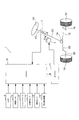
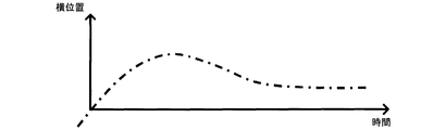
- FIG. 1 It is a figure which shows schematic structure of a driving assistance system. It is a block diagram which shows the flow of the process which LKAECU performs. It is a figure which shows a target track
- the driving support system 1 of this embodiment is mounted on a vehicle, and includes a torque sensor 2, a motor 3, a camera 4, a vehicle speed sensor 5, a yaw rate sensor 6, an acceleration sensor 7, a steering angle sensor 8, and a current detection.
- a circuit 9, a lane keeping assist electronic control device 10, and an electric power steering electronic control device 11 are provided.
- the lane keeping assist electronic control device 10 is referred to as a LKA ECU (Lane Keep Assist Electronic Control Unit) 10.
- the electric power steering electronic control device 11 is referred to as EPSECU (Electric Power Steering Electronic Control Unit) 11.
- a vehicle equipped with the driving support system 1 is referred to as a host vehicle.
- the driving support system 1 performs control to avoid the departure when the host vehicle is about to depart from the lane.
- the handle 101 of the host vehicle is fixed to the first end of the steering shaft 102.
- the first end of the torque sensor 2 is connected to the second end of the steering shaft 102, and the second end of the torque sensor 2 is connected to the first end of the intermediate shaft 103.
- the torque sensor 2 is a sensor for detecting steering torque. Specifically, the torque sensor 2 has a torsion bar that connects the steering shaft 102 and the intermediate shaft 103, and detects the torque applied to the torsion bar based on the twist angle of the torsion bar.
- the motor 3 has a worm gear at the tip of its rotating shaft.
- the worm gear meshes with a worm wheel provided on the intermediate shaft 103. Thereby, the rotation of the motor 3 is transmitted to the intermediate shaft 103.
- the second end of the intermediate shaft 103 is connected to the steering gear box 104.
- the steering gear box 104 is configured by a gear mechanism including a rack and a pinion gear, and the rack teeth mesh with a pinion gear provided at the second end of the intermediate shaft 103. Therefore, when the driver turns the handle 101, the intermediate shaft 103 rotates (that is, the pinion gear rotates), thereby moving the rack to the left and right.
- Tie rods 105 are attached to both ends of the rack, and the tie rods 105 reciprocate left and right together with the rack. Thereby, the direction of the tire 107 is changed by pulling or pushing the knuckle arm 106 ahead of the tie rod 105.
- the camera 4 is attached to the front side of the host vehicle.
- the camera 4 repeatedly captures the road surface ahead of the host vehicle and outputs image data indicating the captured image.
- the vehicle speed sensor 5 detects the traveling speed of the host vehicle and outputs a vehicle speed signal indicating the detection result.
- the yaw rate sensor 6 detects the yaw rate of the host vehicle and outputs a yaw rate signal indicating the detection result.
- the acceleration sensor 7 detects the lateral acceleration of the host vehicle and outputs a lateral acceleration signal indicating the detection result.
- the steering angle sensor 8 detects the steering angle of the host vehicle and outputs a steering angle signal indicating the detection result.
- the current detection circuit 9 detects the current flowing through the motor 3.
- the LKA ECU 10 is configured around a known microcomputer including a CPU, a ROM, a RAM, an I / O, a bus line connecting these components, and the like.
- the CPU executes various processes based on a program stored in a non-transitory tangible storage medium such as a ROM while using the temporary storage function of the RAM.
- the LKA ECU 10 avoids the vehicle from deviating from the lane based on information input from the torque sensor 2, the camera 4, the vehicle speed sensor 5, the yaw rate sensor 6, the acceleration sensor 7, the steering angle sensor 8, and the current detection circuit 9. To perform the operation.
- the LKAECU 10 then outputs a required torque ⁇ tgt indicating the torque required for the motor 3 to the EPS ECU 11 based on the calculation result.
- the EPS ECU 11 is configured around a well-known microcomputer including a CPU, a ROM, a RAM, an I / O, a bus line connecting these components, and the like.
- the CPU executes various processes based on a program stored in a non-transitory tangible storage medium such as a ROM while using the temporary storage function of the RAM.
- EPSECU 11 applies a drive voltage corresponding to the required torque ⁇ tgt from LKA ECU 10 to motor 3 to cause motor 3 to generate a force for steering both tires 107.
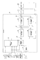
- the LKA ECU 10 includes a lane recognition unit 21, a target trajectory generation unit 22, a road surface camber correction unit 23, a first adder 24, a feedforward steering angle calculation unit 25, a feedback steering angle calculation unit 26, a second An adder 27, a feed forward torque calculator 28, a feedback torque calculator 29, and a third adder 30 are provided.
- the lane recognition unit 21 recognizes a white line dividing the left side and the right side of the traveling lane in which the host vehicle is traveling by performing image processing on the image data input from the camera 4.
- the lane recognition unit 21 calculates the lateral position, the lateral speed, and the departure angle of the host vehicle based on the position where the white line appears in the image data.
- the lateral position of the host vehicle is the position of the host vehicle along a direction perpendicular to the traveling direction of the travel lane in the travel lane.
- the lateral speed of the host vehicle is a moving speed of the host vehicle along a direction perpendicular to the traveling direction of the traveling lane.
- the departure angle is an angle at which the traveling direction of the host vehicle is inclined with respect to the traveling direction of the traveling lane.
- the target track generation unit 22 is based on the position of the white line recognized by the lane recognition unit 21, the lateral position and departure angle of the host vehicle calculated by the lane recognition unit 21, and the vehicle speed signal input from the vehicle speed sensor 5. It is determined whether or not the vehicle departs from the traveling lane. When the target track generation unit 22 determines that the vehicle departs from the travel lane, the target track generation unit 22 determines the target based on the lateral position and the departure angle calculated by the lane recognition unit 21 and the vehicle speed specified by the vehicle speed signal from the vehicle speed sensor 5. Start generating orbit data.
- the target track gradually changes the traveling direction of the host vehicle from the outside of the traveling lane toward the inside of the traveling lane so that the host vehicle finally travels in the center of the traveling lane.
- the target trajectory data includes a plurality of times based on the current time, a lateral position indicating a target trajectory corresponding to each of the plurality of times, a plurality of lateral velocities calculated corresponding to each of the plurality of lateral positions, A plurality of lateral accelerations calculated corresponding to each of the plurality of lateral positions.
- the road surface camber correction unit 23 is based on the information input from the torque sensor 2, the vehicle speed sensor 5, the yaw rate sensor 6, the acceleration sensor 7, and the current detection circuit 9, and the lateral acceleration correction value a CAL ( (To be described later).
- a method of calculating the lateral acceleration correction value a CAL will be described later.
- the first adder 24 uses the lateral acceleration of the lateral position, lateral velocity and lateral acceleration constituting the target trajectory data output from the target trajectory generating unit 22 and the lateral acceleration correction value a output from the road surface camber correcting unit 23.
- An added value obtained by adding CAL (hereinafter referred to as corrected lateral acceleration) is output to the feedforward steering angle calculation unit 25 and the feedback steering angle calculation unit 26.
- the first adder 24 outputs the lateral position and lateral velocity of the lateral position, lateral velocity and lateral acceleration constituting the target trajectory data output from the target trajectory generating unit 22 to the feedback steering angle calculating unit 26.
- the feedforward rudder angle calculation unit 25 calculates a rudder angle when the corrected lateral acceleration output from the first adder 24 acts on the host vehicle based on an arithmetic expression indicating the relationship between the lateral acceleration and the rudder angle. , and it outputs the steering angle as a feedforward steering angle [delta] FF.
- the feedback rudder angle calculation unit 26 performs feedback control so that the lateral position, lateral speed, and lateral acceleration of the host vehicle MC coincide with the lateral position, lateral speed, and lateral acceleration input from the first adder 24, respectively.
- the feedback steering angle ⁇ FB is calculated and output.
- the lateral position and the lateral speed of the host vehicle MC are calculated by the lane recognition unit 21. Further, the lateral acceleration of the host vehicle MC is calculated based on the yaw rate detected by the yaw rate sensor 6 and the vehicle speed detected by the vehicle speed sensor 5.
- the second adder 27 requests an added value obtained by adding the feed forward steering angle ⁇ FF output from the feed forward steering angle calculation unit 25 and the feedback steering angle ⁇ FB output from the feedback steering angle calculation unit 26. Output as the steering angle ⁇ tgt .
- the feed forward torque calculation unit 28 converts the required steering angle ⁇ tgt output from the second adder 27 into torque, and outputs this torque as feed forward torque ⁇ FF .
- the relationship between the lateral acceleration and the torque (hereinafter referred to as the lateral acceleration-torque conversion relationship) is obtained in advance from vehicle specifications, and the feedforward torque calculator 28 calculates the relationship between the lateral acceleration-torque conversion relationship and the required steering angle ⁇ . on the basis of the lateral acceleration corresponding to tgt, it calculates a torque corresponding to the required steering angle [delta] tgt. Note that the lateral acceleration corresponding to the required steering angle ⁇ tgt is calculated based on an arithmetic expression indicating the relationship between the lateral acceleration and the steering angle.
- the feedback torque calculator 29 calculates a feedback torque ⁇ FB for feedback control so that the steering angle detected by the steering angle sensor 8 matches the required steering angle ⁇ tgt output from the second adder 27. Output.
- the third adder 30 adds an addition value obtained by adding the feedforward torque ⁇ FF output from the feedforward torque calculation unit 28 and the feedback torque ⁇ FB output from the feedback torque calculation unit 29 as a required torque ⁇ tgt. Output to EPSECU 11.
- the EPS ECU 11 controls the motor 3 based on the required torque ⁇ tgt output from the third adder 30. As a result, the host vehicle MC travels along the target track.
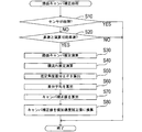
- the road surface camber correction process is a process repeatedly executed during the operation of the LKA ECU 10.
- the CPU of the LKA ECU 10 first determines in S10 whether or not the sensor used for the calculation has failed as shown in FIG. Sensors used for the calculation are the torque sensor 2, the vehicle speed sensor 5, the yaw rate sensor 6, the acceleration sensor 7, and the current detection circuit 9.
- the road camber correction process is temporarily terminated.
- the vehicle speed of the host vehicle is equal to or higher than the preset calculation possible vehicle speed (for example, 40 km / h in this embodiment) in S20. Determine whether or not.
- the vehicle speed of the host vehicle is less than the computable vehicle speed (S20: NO)
- the road surface camber correction process is temporarily ended.
- road surface camber estimation calculation is performed in S30.
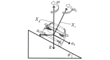
- the vehicle speed of the host vehicle is expressed as ⁇ [m / s]
- the gravitational acceleration is expressed as g [m / s 2 ].
- the camber angle is ⁇ [rad]
- the centrifugal acceleration is a CF [m / s 2 ]
- the yaw rate with respect to the vertical axis Xg is ⁇ [rad / s]
- the yaw rate with respect to the vehicle vertical axis Xc is ⁇ S.
- the lateral acceleration detected by the acceleration sensor 7 is expressed as a S [m / s 2 ].
- the yaw rate ⁇ S is a yaw rate detected by the yaw rate sensor 6.
- the camber angle ⁇ is expressed by the following equation (4) using the vehicle speed ⁇ detected by the vehicle speed sensor 5, the yaw rate ⁇ S detected by the yaw rate sensor 6, and the lateral acceleration a S detected by the acceleration sensor 7. ).
- the camber angle ⁇ calculated by the above equation (4) is calculated as the camber estimated angle ⁇ G by the yaw rate sensor 6 and the acceleration sensor 7, and the process ends.
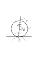
- the yaw rate ⁇ S detected by the yaw rate sensor 6 is cos ⁇ times the yaw rate ⁇ with respect to the vertical axis Xg. That is, as the camber angle increases, the yaw rate ⁇ S decreases. For this reason, if the turning radius of the road on which the host vehicle is traveling is estimated based on the yaw rate detected by the yaw rate sensor 6, this estimated turning radius is larger than the actual turning radius.
- the estimated lateral acceleration estimated from the yaw rate ⁇ S detected by the yaw rate sensor 6 is expressed as a E [m / s 2 ]
- the estimated lateral acceleration a E is calculated by the following equation (5).
- the estimated lateral acceleration a E estimated from the yaw rate ⁇ S is larger than the lateral acceleration a S detected by the acceleration sensor 7 by g ⁇ sin ⁇ . That is, as the camber angle increases, the difference between the estimated lateral acceleration a E estimated from the yaw rate ⁇ S and the lateral acceleration a S detected by the acceleration sensor 7 increases.
- the front cornering force 2 ⁇ F f acts on the applied force point Pc behind the ground contact point Pg of the tire 107.
- the tie rod axial force F t acts on a connection point Pn between the tie rod 105 and the knuckle arm 106.
- the relationship between the front cornering force 2 ⁇ F f [N] and the tie rod axial force F t [N] can be obtained by the moment around the kingpin axis KP and is expressed by the following equation (7).
- the effective knuckle arm radius is expressed as R n [m]
- the caster rail when the caster angle is ⁇ c is expressed as n 0 [m]
- the pneumatic trail is expressed as n f [m].
- the effective knuckle arm radius R n [m] is represented by the following formula (9).
- the steering overwall gear ratio is expressed as N g [ ⁇ ]
- the stroke ratio (specific list) is expressed as S r [m / rev].
- the stroke ratio (ratio) Sr is expressed by the following equation (10).
- the lock-to-lock rotation speed is expressed as ⁇
- the rack stroke is expressed as L r [m].
- the tie rod axial force F t [N] is expressed by the following expression (11).
- the steering torque generated by steering the handle 101 is MT [Nm]
- the torque transmission efficiency is ⁇ w [ ⁇ ]
- the value obtained by dividing the rated torque of the motor 3 by the rated current is k t. [Nm / A]
- the current flowing through the motor 3 is I m [A]
- the motor gear ratio is iw [ ⁇ ]
- the efficiency of the gear mechanism composed of the rack and pinion gear of the steering gear box 104 is ⁇ p [ ⁇ ]. It is written.
- intermediate shaft torque T i the torque T i of the intermediate shaft 103 (hereinafter referred to as intermediate shaft torque T i ) is expressed by the following equation (12).
- the relationship between the front wheel cornering force F f and the rear wheel cornering force F r is expressed by the following equation (15).
- the distance between the vehicle center of gravity and the front wheel axis is expressed as l f
- the distance between the vehicle center of gravity and the rear wheel axis is expressed as l r .
- the distance l f between the vehicle center of gravity and the front wheel axis and the distance l r between the vehicle center of gravity and the rear wheel axis are expressed by the following expressions (16) and (17), respectively.
- the vehicle wheel base is denoted by l
- the front vehicle mass with respect to the vehicle center of gravity is denoted by m f
- the rear vehicle mass with respect to the vehicle center of gravity is denoted by m r. Yes.
- planar yaw rate ⁇ std when the vehicle is making a steady circular turn on a flat road.
- the intermediate shaft torque Ti is calculated based on the motor current value detected by the current detection circuit 9, the steering torque detected by the torque sensor 2, and the above equation (12).
- the plane yaw rate ⁇ std is calculated based on the above equation (24) and the above equation (25).
- a yaw rate difference ⁇ between the plane yaw rate ⁇ std and the yaw rate ⁇ S detected by the yaw rate sensor 6 is calculated, and a lateral acceleration ⁇ a (hereinafter, difference) corresponding to the yaw rate difference ⁇ is calculated by the following equation (26).
- an average value ⁇ ave of the estimated angle difference ⁇ calculated in S50 (hereinafter referred to as difference average ⁇ ave ) is calculated. Further, in S70, as shown in the following equation (29), an addition value obtained by adding the camber estimated angle ⁇ G calculated in S30 and the difference average ⁇ ave calculated in S60 is calculated as a camber correction value ⁇ CAL. To do.
- FIG. 8 is a graph showing changes with time of calculation results of the camber estimated angle ⁇ G , the estimated angle ⁇ std, and the camber correction value ⁇ CAL .
- the calculation result of the camber estimated angle ⁇ G is stable over time, but is offset due to the influence of the zero point deviation of the acceleration sensor 7.
- the calculation result of the estimated angle ⁇ std varies with the passage of time due to the influence of the vehicle model error.
- the offset amount is reduced more than the camber estimated angle ⁇ G, and the fluctuation amount with respect to time is reduced more than the estimated angle ⁇ std .
- the lane recognition unit 21 recognizes a travel lane in which the host vehicle travels. Further, the target trajectory generation unit 22, the first adder 24, the feed forward steering angle calculation unit 25, the feedback steering angle calculation unit 26, the second adder 27, the feed forward torque calculation unit 28, the feedback torque calculation unit 29, and the third The adder 30 calculates a required torque ⁇ tgt for controlling the steering of the host vehicle so as to suppress the host vehicle from deviating from the traveling lane.
- the road surface camber correcting unit 23 detects a camber estimated angle ⁇ G that is an inclination angle of the road surface of the traveling lane in which the host vehicle is traveling (S30). Further, the road surface camber correcting unit 23 detects the lateral flow of the host vehicle by calculating the yaw rate difference ⁇ (S40). Then, the road surface camber correcting unit 23 corrects the required torque ⁇ tgt by calculating the lateral acceleration correction value a CAL based on the camber estimated angle ⁇ G and the yaw rate difference ⁇ (S60 to S80).
- the LKA ECU 10 detects not only the road camber of the travel lane but also the lateral flow of the host vehicle, and based on the road camber and the lateral flow, steers the host vehicle so as to suppress the departure of the host vehicle from the travel lane.
- the required torque ⁇ tgt for control can be calculated.
- LKA ECU10 can improve the maintenance performance which suppresses that the own vehicle deviates from a travel lane, and maintains a vehicle in a travel lane.
- the lateral flow of the vehicle is a phenomenon in which the vehicle moves toward the right side or the left side against the driver's intention. For example, a lateral flow of the vehicle is occurring when the driver continues to steer the steering wheel to the right or left side even though the vehicle is traveling straight on a flat straight road. Possible causes of the lateral flow of the vehicle include a lateral wind flowing along the width direction of the vehicle and a vehicle alignment shift.
- the LKA ECU 10 also determines a yaw rate difference ⁇ that is a difference between the plane yaw rate ⁇ std that is a yaw rate estimated based on the intermediate shaft torque T i applied to the intermediate shaft 103 and the yaw rate ⁇ S detected by the yaw rate sensor 6. Based on this, the lateral flow of the host vehicle is detected (S40). In other words, the LKA ECU 10 detects the lateral flow of the host vehicle based on the torque generated by the driver's steering so as to suppress the host vehicle from flowing laterally due to a side wind and a vehicle alignment shift.
- the LKA ECU 10 calculates an inclination angle corresponding to the yaw rate difference ⁇ as the estimated angle ⁇ std (S40). And LKAECU10 based and camber estimated angle theta G, the sum of the difference average theta ave is an average value of the difference between the camber estimated angle theta G and the estimated angle theta std (camber correction value theta CAL), the required torque ⁇ tgt is corrected (S60 to S80).
- the LKA ECU 10 can calculate the required torque ⁇ tgt whose value is stable with the passage of time by reducing the influence of the zero point deviation of the acceleration sensor 7 and the influence of the vehicle model error.
- the LKA ECU 10 is a lane keeping assist device according to the present invention.
- the lane recognition unit 21 is a traveling lane recognition unit in the present invention.
- the adder 30 is a control amount calculation means in the present invention.
- the process of S30 is the inclination angle detection means in this invention.
- the process of S40 is a cross flow detection means in the present invention.
- the processes of S60 to S80 are correction means in the present invention.
- the travel lane is a travel lane in the present invention.
- the required torque ⁇ tgt is a steering control amount in the present invention.
- the camber estimated angle ⁇ G is the road surface inclination angle in the present invention.
- the plane yaw rate ⁇ std is the estimated yaw rate in the present invention.
- the estimated angle ⁇ std is the lateral flow inclination angle in the present invention.
- the handle 101, the steering shaft 102, the intermediate shaft 103, the steering gear box 104, the tie rod 105, and the knuckle arm 106 are the steering device in the present invention.
- the functions of one component in the above embodiment may be distributed as a plurality of components, or the functions of a plurality of components may be integrated into one component.
- at least a part of the configuration of the above embodiment may be replaced with a known configuration having the same function.
- at least a part of the configuration of the above embodiment may be added to or replaced with the configuration of the other embodiment.
- all the aspects included in the technical idea specified only by the wording described in the claim are embodiment of this invention.
- Driving support system 10 ... LKAECU DESCRIPTION OF SYMBOLS 21 ... Lane recognition part 22 ... Target track generation part 23 ... Road surface camber correction part 24 ... Adder 25 ... Feed forward steering angle calculating part 26 ... Feedback steering angle calculating part 27 ... Adder 28 ... Feed forward torque calculating part 29 ... Feedback Torque calculator 30 ... adder
Landscapes
- Engineering & Computer Science (AREA)
- Transportation (AREA)
- Mechanical Engineering (AREA)
- Automation & Control Theory (AREA)
- Physics & Mathematics (AREA)
- Mathematical Physics (AREA)
- General Physics & Mathematics (AREA)
- Chemical & Material Sciences (AREA)
- Combustion & Propulsion (AREA)
- Steering Control In Accordance With Driving Conditions (AREA)
- Traffic Control Systems (AREA)
Abstract
Cette invention concerne un bloc de commande électronique d'assistance de suivi de voie (LKAECU) (10), comprenant une unité de reconnaissance de voie (21) qui reconnaît une voie de circulation le long de laquelle se déplace un véhicule. De plus, une unité de génération de trajectoire cible (22), un premier additionneur (24), une unité prédictive de calcul d'angle de braquage (25), une unité de calcul d'angle de braquage à rétroaction (26), un deuxième additionneur (27), une unité prédictive de calcul de couple (28), une unité de calcul de couple à rétroaction (29), et un troisième additionneur (30) calculent un couple de requête τtgt pour commander le braquage du véhicule de telle sorte que l'éloignement du véhicule à partir de la voie de circulation est inhibé. De plus, une unité de correction de bombement de surface de route (23) détecte un angle de bombement estimé θG, c'est-à-dire l'angle d'inclinaison de la surface de route de la voie de circulation le long de laquelle se déplace le véhicule. En outre, l'unité de correction de bombement de surface de route (23) calcule la différence d'amplitude de lacet ∆omega pour détecter la dérive du véhicule. L'unité de correction de bombement de surface de route (23) corrige le couple de requête τtgt sur la base de l'angle de bombement estimé θG et de la différence d'amplitude de lacet ∆omega.
Priority Applications (1)
| Application Number | Priority Date | Filing Date | Title |
|---|---|---|---|
| US15/739,131 US10640110B2 (en) | 2015-06-26 | 2016-06-22 | Lane keep assist device |
Applications Claiming Priority (2)
| Application Number | Priority Date | Filing Date | Title |
|---|---|---|---|
| JP2015-128887 | 2015-06-26 | ||
| JP2015128887A JP6332167B2 (ja) | 2015-06-26 | 2015-06-26 | 車線維持支援装置 |
Publications (1)
| Publication Number | Publication Date |
|---|---|
| WO2016208608A1 true WO2016208608A1 (fr) | 2016-12-29 |
Family
ID=57586402
Family Applications (1)
| Application Number | Title | Priority Date | Filing Date |
|---|---|---|---|
| PCT/JP2016/068461 WO2016208608A1 (fr) | 2015-06-26 | 2016-06-22 | Dispositif d'assistance de suivi de voie |
Country Status (3)
| Country | Link |
|---|---|
| US (1) | US10640110B2 (fr) |
| JP (1) | JP6332167B2 (fr) |
| WO (1) | WO2016208608A1 (fr) |
Cited By (2)
| Publication number | Priority date | Publication date | Assignee | Title |
|---|---|---|---|---|
| CN109606362A (zh) * | 2018-11-19 | 2019-04-12 | 江苏大学 | 一种基于道路曲率的可拓前馈车道保持控制方法 |
| CN109849900A (zh) * | 2019-03-14 | 2019-06-07 | 武汉理工大学 | 一种基于车路协同的汽车主动转向控制系统及方法 |
Families Citing this family (13)
| Publication number | Priority date | Publication date | Assignee | Title |
|---|---|---|---|---|
| IT201600109633A1 (it) * | 2016-10-31 | 2018-05-01 | Magneti Marelli Spa | Procedimento e sistema di controllo adattivo in un veicolo terrestre per l'inseguimento di un percorso, particolarmente in uno scenario di guida autonoma. |
| US11214280B2 (en) * | 2017-01-26 | 2022-01-04 | Ford Global Technologies, Llc | Autonomous vehicle providing driver education |
| US10723380B2 (en) * | 2017-02-24 | 2020-07-28 | Ford Global Technologies, Llc | Systems and methods to control steering of a vehicle |
| FR3066985B1 (fr) * | 2017-06-06 | 2020-10-30 | Renault Sas | Dispositif d'assistance a la conduite d'un vehicule automobile dans une voie de circulation |
| KR102335985B1 (ko) * | 2017-07-04 | 2021-12-07 | 현대자동차주식회사 | 조향각 제어 장치, 그를 포함한 차로 추종 보조 시스템 및 그 방법 |
| WO2020008515A1 (fr) * | 2018-07-03 | 2020-01-09 | 三菱電機株式会社 | Appareil de commande de véhicule |
| JP7028115B2 (ja) * | 2018-09-11 | 2022-03-02 | トヨタ自動車株式会社 | 車両用操舵支援装置 |
| US11604476B1 (en) | 2018-10-05 | 2023-03-14 | Glydways Inc. | Road-based vehicle guidance system |
| CN113104037B (zh) * | 2019-12-24 | 2022-08-30 | 浙江吉利汽车研究院有限公司 | 一种车辆方向盘转向角度确定方法及系统 |
| DE102020208391A1 (de) * | 2020-07-03 | 2022-01-05 | Continental Automotive Gmbh | Verfahren zur teil- oder vollautonomen Führung eines Kraftfahrzeugs |
| CN113415276B (zh) * | 2021-07-30 | 2022-10-14 | 东风商用车有限公司 | 一种智能驾驶预瞄控制方法、装置和存储介质 |
| DE102021212019B4 (de) * | 2021-10-25 | 2023-07-06 | Volkswagen Aktiengesellschaft | Verfahren zum sicheren Beenden einer Bankettfahrt eines Kraftfahrzeugs |
| CN115123294A (zh) * | 2022-06-16 | 2022-09-30 | 中国第一汽车股份有限公司 | 车辆控制方法、车辆、存储介质及电子装置 |
Citations (3)
| Publication number | Priority date | Publication date | Assignee | Title |
|---|---|---|---|---|
| JP2005280368A (ja) * | 2004-03-26 | 2005-10-13 | Mitsubishi Motors Corp | 車両用パワーステアリング装置及び車両用外乱推定装置 |
| JP2006236238A (ja) * | 2005-02-28 | 2006-09-07 | Aisin Seiki Co Ltd | 車両のレーン走行支援装置 |
| JP2014024448A (ja) * | 2012-07-26 | 2014-02-06 | Fuji Heavy Ind Ltd | 車両の操舵支援装置 |
Family Cites Families (6)
| Publication number | Priority date | Publication date | Assignee | Title |
|---|---|---|---|---|
| GB9317983D0 (en) * | 1993-08-28 | 1993-10-13 | Lucas Ind Plc | A driver assistance system for a vehicle |
| US7451032B2 (en) * | 2004-06-02 | 2008-11-11 | Ford Global Technologies, Llc | System and method for determining desired yaw rate and lateral velocity for use in a vehicle dynamic control system |
| KR101567207B1 (ko) * | 2014-04-16 | 2015-11-13 | 현대자동차주식회사 | 차량 제어 시스템 및 그의 자율 주행 방법 |
| JP5947849B2 (ja) * | 2014-09-17 | 2016-07-06 | 富士重工業株式会社 | 車両の車線逸脱防止制御装置 |
| US20160096546A1 (en) * | 2014-10-03 | 2016-04-07 | Delphi Technologies, Inc. | Lane departure steering correction with road camber and crosswind compensation |
| DE102015012560A1 (de) * | 2014-10-07 | 2016-04-07 | Bomag Gmbh | Fahrstand für eine Baumaschine und Baumaschine mit einem Fahrstand |
-
2015
- 2015-06-26 JP JP2015128887A patent/JP6332167B2/ja active Active
-
2016
- 2016-06-22 US US15/739,131 patent/US10640110B2/en active Active
- 2016-06-22 WO PCT/JP2016/068461 patent/WO2016208608A1/fr active Application Filing
Patent Citations (3)
| Publication number | Priority date | Publication date | Assignee | Title |
|---|---|---|---|---|
| JP2005280368A (ja) * | 2004-03-26 | 2005-10-13 | Mitsubishi Motors Corp | 車両用パワーステアリング装置及び車両用外乱推定装置 |
| JP2006236238A (ja) * | 2005-02-28 | 2006-09-07 | Aisin Seiki Co Ltd | 車両のレーン走行支援装置 |
| JP2014024448A (ja) * | 2012-07-26 | 2014-02-06 | Fuji Heavy Ind Ltd | 車両の操舵支援装置 |
Cited By (3)
| Publication number | Priority date | Publication date | Assignee | Title |
|---|---|---|---|---|
| CN109606362A (zh) * | 2018-11-19 | 2019-04-12 | 江苏大学 | 一种基于道路曲率的可拓前馈车道保持控制方法 |
| CN109606362B (zh) * | 2018-11-19 | 2020-06-09 | 江苏大学 | 一种基于道路曲率的可拓前馈车道保持控制方法 |
| CN109849900A (zh) * | 2019-03-14 | 2019-06-07 | 武汉理工大学 | 一种基于车路协同的汽车主动转向控制系统及方法 |
Also Published As
| Publication number | Publication date |
|---|---|
| JP6332167B2 (ja) | 2018-05-30 |
| JP2017013520A (ja) | 2017-01-19 |
| US10640110B2 (en) | 2020-05-05 |
| US20180170377A1 (en) | 2018-06-21 |
Similar Documents
| Publication | Publication Date | Title |
|---|---|---|
| JP6332167B2 (ja) | 車線維持支援装置 | |
| JP4492471B2 (ja) | パワーステアリング装置。 | |
| EP1862374B1 (fr) | Dispositif de commande de direction pour vehicules | |
| CN104002860B (zh) | 电动转向设备 | |
| JP5170496B2 (ja) | 電動パワーステアリング装置 | |
| WO2016208627A1 (fr) | Dispositif d'assistance au maintien dans une file | |
| US11820425B2 (en) | Steering angle calculation apparatus and motor control apparatus including the same | |
| US8186477B2 (en) | Rear-wheel steering vehicle | |
| JP2007296947A (ja) | 車両の操舵装置 | |
| JP5525357B2 (ja) | サーボ制御装置 | |
| JPH11198844A (ja) | 操舵力制御装置 | |
| JP2019031169A (ja) | 車両の操舵制御装置 | |
| JP4692403B2 (ja) | 車両の操舵装置 | |
| JP2015151048A (ja) | 車両用軌跡制御装置 | |
| JP2017001625A (ja) | 車両用操舵装置 | |
| JP5735895B2 (ja) | 操舵支援装置 | |
| JP2010234935A (ja) | 車両の後輪トー角制御装置 | |
| JP2008174168A (ja) | 車両の後輪転舵制御装置 | |
| JP2010167817A (ja) | 操舵制御装置及びプログラム | |
| JP5617499B2 (ja) | 車両用舵角制御装置 | |
| JP4135158B2 (ja) | 車両の前後輪舵角制御装置 | |
| JP6535490B2 (ja) | 車両の車線逸脱防止制御装置 | |
| JP5088008B2 (ja) | 車体スリップ角制御装置及びプログラム | |
| JP5303333B2 (ja) | 車両の後輪操舵制御装置 | |
| JP5326019B2 (ja) | 後輪トー角制御装置 |
Legal Events
| Date | Code | Title | Description |
|---|---|---|---|
| 121 | Ep: the epo has been informed by wipo that ep was designated in this application |
Ref document number: 16814378 Country of ref document: EP Kind code of ref document: A1 |
|
| WWE | Wipo information: entry into national phase |
Ref document number: 15739131 Country of ref document: US |
|
| NENP | Non-entry into the national phase |
Ref country code: DE |
|
| 122 | Ep: pct application non-entry in european phase |
Ref document number: 16814378 Country of ref document: EP Kind code of ref document: A1 |